installation, operation, and maintenance...
TRANSCRIPT

OM---05171---OE01January 5, 2001
ACEG
THE GORMAN-RUPP COMPANY D MANSFIELD, OHIOGORMAN-RUPP OF CANADA LIMITED D ST. THOMAS, ONTARIO, CANADA Printed in U.S.A.
ECopyright by the Gorman-Rupp Company
INSTALLATION, OPERATION,AND MAINTENANCE MANUAL
WITH PARTS LIST
60 SERIES PUMP
62 1/2D1---CH23 S/G
MODEL
The engine exhaust from thisproduct contains chemicalsknown to the State of California tocause cancer, birth defects orother reproductive harm.
TABLE OF CONTENTS
i
INTRODUCTION PAGE I --- 1. . . . . . . . . . . . . . . . . . . . . . . . . . . . . . . . . . . . . . . . . . . . . . . . . . .
SAFETY --- SECTION A PAGE A --- 1. . . . . . . . . . . . . . . . . . . . . . . . . . . . . . . . . . . . . . . . . . . .
INSTALLATION --- SECTION B PAGE B --- 1. . . . . . . . . . . . . . . . . . . . . . . . . . . . . . . . . . . . .
Pump Dimensions PAGE B --- 1. . . . . . . . . . . . . . . . . . . . . . . . . . . . . . . . . . . . . . . . . . . . . . . . . . . . .PREINSTALLATION INSPECTION PAGE B --- 1. . . . . . . . . . . . . . . . . . . . . . . . . . . . . . . . . . . . . . . . . . . .POSITIONING PUMP PAGE B --- 2. . . . . . . . . . . . . . . . . . . . . . . . . . . . . . . . . . . . . . . . . . . . . . . . . . . . . . .
Mounting PAGE B --- 2. . . . . . . . . . . . . . . . . . . . . . . . . . . . . . . . . . . . . . . . . . . . . . . . . . . . . . . . . . . . .SUCTION AND DISCHARGE PIPING PAGE B --- 2. . . . . . . . . . . . . . . . . . . . . . . . . . . . . . . . . . . . . . . . .
Materials PAGE B --- 2. . . . . . . . . . . . . . . . . . . . . . . . . . . . . . . . . . . . . . . . . . . . . . . . . . . . . . . . . . . . . .Line Configuration PAGE B --- 2. . . . . . . . . . . . . . . . . . . . . . . . . . . . . . . . . . . . . . . . . . . . . . . . . . . . . .Connections to Pump PAGE B --- 2. . . . . . . . . . . . . . . . . . . . . . . . . . . . . . . . . . . . . . . . . . . . . . . . . .Gauges PAGE B --- 2. . . . . . . . . . . . . . . . . . . . . . . . . . . . . . . . . . . . . . . . . . . . . . . . . . . . . . . . . . . . . . .
SUCTION LINES PAGE B --- 3. . . . . . . . . . . . . . . . . . . . . . . . . . . . . . . . . . . . . . . . . . . . . . . . . . . . . . . . . . .Fittings PAGE B --- 3. . . . . . . . . . . . . . . . . . . . . . . . . . . . . . . . . . . . . . . . . . . . . . . . . . . . . . . . . . . . . . .Strainers PAGE B --- 3. . . . . . . . . . . . . . . . . . . . . . . . . . . . . . . . . . . . . . . . . . . . . . . . . . . . . . . . . . . . . .Sealing PAGE B --- 3. . . . . . . . . . . . . . . . . . . . . . . . . . . . . . . . . . . . . . . . . . . . . . . . . . . . . . . . . . . . . . .Suction Lines In Sumps PAGE B --- 3. . . . . . . . . . . . . . . . . . . . . . . . . . . . . . . . . . . . . . . . . . . . . . . . .Suction Line Positioning PAGE B --- 3. . . . . . . . . . . . . . . . . . . . . . . . . . . . . . . . . . . . . . . . . . . . . . . .
DISCHARGE LINES PAGE B --- 4. . . . . . . . . . . . . . . . . . . . . . . . . . . . . . . . . . . . . . . . . . . . . . . . . . . . . . . .Siphoning PAGE B --- 4. . . . . . . . . . . . . . . . . . . . . . . . . . . . . . . . . . . . . . . . . . . . . . . . . . . . . . . . . . . . .Valves PAGE B --- 4. . . . . . . . . . . . . . . . . . . . . . . . . . . . . . . . . . . . . . . . . . . . . . . . . . . . . . . . . . . . . . . .
OPERATION --- SECTION C PAGE C --- 1. . . . . . . . . . . . . . . . . . . . . . . . . . . . . . . . . . . . . . .
PRIMING PAGE C --- 1. . . . . . . . . . . . . . . . . . . . . . . . . . . . . . . . . . . . . . . . . . . . . . . . . . . . . . . . . . . . . . . . .Exhaust Primer PAGE C --- 1. . . . . . . . . . . . . . . . . . . . . . . . . . . . . . . . . . . . . . . . . . . . . . . . . . . . . . . .
STARTING PAGE C --- 1. . . . . . . . . . . . . . . . . . . . . . . . . . . . . . . . . . . . . . . . . . . . . . . . . . . . . . . . . . . . . . . .OPERATION PAGE C --- 2. . . . . . . . . . . . . . . . . . . . . . . . . . . . . . . . . . . . . . . . . . . . . . . . . . . . . . . . . . . . . .
Leakage PAGE C --- 2. . . . . . . . . . . . . . . . . . . . . . . . . . . . . . . . . . . . . . . . . . . . . . . . . . . . . . . . . . . . . .Liquid Temperature And Overheating PAGE C --- 2. . . . . . . . . . . . . . . . . . . . . . . . . . . . . . . . . . . . .Strainer Check PAGE C --- 2. . . . . . . . . . . . . . . . . . . . . . . . . . . . . . . . . . . . . . . . . . . . . . . . . . . . . . . . .Pump Vacuum Check PAGE C --- 2. . . . . . . . . . . . . . . . . . . . . . . . . . . . . . . . . . . . . . . . . . . . . . . . . .
STOPPING PAGE C --- 2. . . . . . . . . . . . . . . . . . . . . . . . . . . . . . . . . . . . . . . . . . . . . . . . . . . . . . . . . . . . . . . .Cold Weather Preservation PAGE C --- 3. . . . . . . . . . . . . . . . . . . . . . . . . . . . . . . . . . . . . . . . . . . . . .
TROUBLESHOOTING --- SECTION D PAGE D --- 1. . . . . . . . . . . . . . . . . . . . . . . . . . . . . . .
PREVENTIVE MAINTENANCE PAGE D --- 2. . . . . . . . . . . . . . . . . . . . . . . . . . . . . . . . . . . . . . . . . . . . . . . . . .
PUMP MAINTENANCE AND REPAIR --- SECTION E PAGE E --- 1. . . . . . . . . . . . . . . . .
STANDARD PERFORMANCE CURVE FOR PUMP MODEL 62 1/2D1---CH23 S/G PAGE E --- 1. .PARTS LIST:
Pump Model PAGE E --- 3. . . . . . . . . . . . . . . . . . . . . . . . . . . . . . . . . . . . . . . . . . . . . . . . . . . . . . . . . .Pump End Assembly PAGE E --- 5. . . . . . . . . . . . . . . . . . . . . . . . . . . . . . . . . . . . . . . . . . . . . . . . . . .Exhaust Primer Assembly PAGE E --- 6. . . . . . . . . . . . . . . . . . . . . . . . . . . . . . . . . . . . . . . . . . . . . . .
PUMP AND SEAL DISASSEMBLY AND REASSEMBLY PAGE E --- 7. . . . . . . . . . . . . . . . . . . . . . . . .

TABLE OF CONTENTS(continued)
ii
Discharge Check Valve Disassembly PAGE E --- 7. . . . . . . . . . . . . . . . . . . . . . . . . . . . . . . . . . . . .Exhaust Primer Disassembly PAGE E --- 7. . . . . . . . . . . . . . . . . . . . . . . . . . . . . . . . . . . . . . . . . . . .Pump Disassembly PAGE E --- 7. . . . . . . . . . . . . . . . . . . . . . . . . . . . . . . . . . . . . . . . . . . . . . . . . . . . .Seal Removal and Disassembly PAGE E --- 8. . . . . . . . . . . . . . . . . . . . . . . . . . . . . . . . . . . . . . . . . .Seal Reassembly and Installation PAGE E --- 8. . . . . . . . . . . . . . . . . . . . . . . . . . . . . . . . . . . . . . . .Impeller Installation PAGE E --- 10. . . . . . . . . . . . . . . . . . . . . . . . . . . . . . . . . . . . . . . . . . . . . . . . . . . . .Pump Reassembly PAGE E --- 10. . . . . . . . . . . . . . . . . . . . . . . . . . . . . . . . . . . . . . . . . . . . . . . . . . . . .Exhaust Primer Reassembly PAGE E --- 10. . . . . . . . . . . . . . . . . . . . . . . . . . . . . . . . . . . . . . . . . . . . .Discharge Check Valve Reassembly PAGE E --- 11. . . . . . . . . . . . . . . . . . . . . . . . . . . . . . . . . . . . . .
LUBRICATION PAGE E --- 11. . . . . . . . . . . . . . . . . . . . . . . . . . . . . . . . . . . . . . . . . . . . . . . . . . . . . . . . . . . . .Seal Assembly PAGE E --- 11. . . . . . . . . . . . . . . . . . . . . . . . . . . . . . . . . . . . . . . . . . . . . . . . . . . . . . . . .Engine PAGE E --- 11. . . . . . . . . . . . . . . . . . . . . . . . . . . . . . . . . . . . . . . . . . . . . . . . . . . . . . . . . . . . . . . .
60 SERIES OM--05171
PAGE I -- 1INTRODUCTION
INTRODUCTION
This Installation, Operation, and Maintenancemanual is designed to help you achieve the bestperformance and longest life from your Gorman-Rupp pump.
This pump is a 60 Series, single-stage centrifugalmodel designed for agricultural or fire fighting ser-vice. It is close-coupled to a Kohler CH23 v-twin cyl-inder O.H.V. air cooled gasoline engine and pro-tected by a wrap-around roll cage with rubbermounting feet. The pump features compact, light
weight design for portability, as well as ruggedconstruction for easy, low-cost maintenance. Thebasic material of construction for wetted parts isaluminum with bronze wear ring, and a self lubri-cated mechanical seal.
If there are any questions regarding the pump or itsapplication which are not covered in this manual orin other literature accompanying this unit, pleasecontact your Gorman-Rupp distributor, or write:
The Gorman-Rupp Company or Gorman-Rupp of Canada LimitedP.O. Box 1217 70 Burwell RoadMansfield, Ohio 44901--1217 St. Thomas, Ontario N5P 3R7
For information or technical assistance on the engine, contact the engine manufacturer’s local dealer orrepresentative.
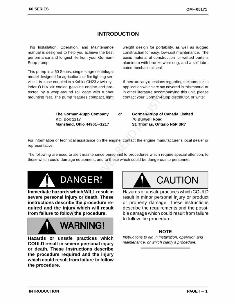
The following are used to alert maintenance personnel to procedures which require special attention, tothose which could damage equipment, and to those which could be dangerous to personnel:
Immediate hazards which WILL result insevere personal injury or death. Theseinstructions describe the procedure re-quired and the injury which will resultfrom failure to follow the procedure.
Hazards or unsafe practices whichCOULD result in severe personal injuryor death. These instructions describethe procedure required and the injurywhich could result from failure to followthe procedure.
Hazards or unsafe practices which COULDresult in minor personal injury or productor property damage. These instructionsdescribe the requirements and the possi-ble damage which could result from failureto follow the procedure.
NOTEInstructions to aid in installation, operation,andmaintenance, or which clarify a procedure.
60 SERIES OM--05171
PAGE A -- 1SAFETY
SAFETY --- SECTION A
This information applies to 60 SeriesEngine Driven pumps. Refer to the man-ual accompanying the engine before at-tempting to begin operation.
This manual will alert personnel toknown procedures which require spe-cial attention, to those which coulddamage equipment, and to those whichcould be dangerous to personnel. How-ever, this manual cannot possibly antici-pate and provide detailed instructionsand precautions for every situation thatmight occur during maintenance of theunit. Therefore, it is the responsibility ofthe owner/maintenance personnel toensure that only safe, established main-tenance procedures are used, and thatany procedures not addressed in thismanual are performed only after estab-lishing that neither personal safety norpump integrity are compromised bysuch practices.
Before attempting to open or service thepump:
1. Familiarize yourself with this man-ual.
2. Shutdown the engine and discon-nect the park plug wires to ensurethat the pump will remain inopera-tive.
3. Allow the pump to completely coolif overheated.
4. Check the temperature beforeopening any covers, plates, orplugs.
5. Close the suction and dischargevalves.
6. Vent the pump slowly and cau-tiously.
7. Drain the pump.
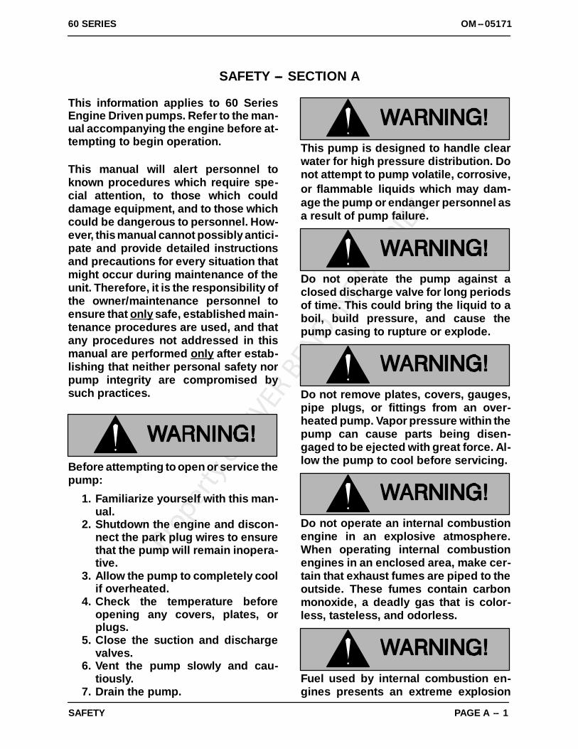
This pump is designed to handle clearwater for high pressure distribution. Donot attempt to pump volatile, corrosive,or flammable liquids which may dam-age the pump or endanger personnel asa result of pump failure.
Do not operate the pump against aclosed discharge valve for long periodsof time. This could bring the liquid to aboil, build pressure, and cause thepump casing to rupture or explode.
Do not remove plates, covers, gauges,pipe plugs, or fittings from an over-heated pump. Vapor pressure within thepump can cause parts being disen-gaged to be ejected with great force. Al-low the pump to cool before servicing.
Do not operate an internal combustionengine in an explosive atmosphere.When operating internal combustionengines in an enclosed area, make cer-tain that exhaust fumes are piped to theoutside. These fumes contain carbonmonoxide, a deadly gas that is color-less, tasteless, and odorless.
Fuel used by internal combustion en-gines presents an extreme explosion
60 SERIESOM--05171
PAGE A -- 2 SAFETY
and fire hazard. Make certain that allfuel lines are securely connected andfree of leaks. Never refuel a hot or run-ning engine. Avoid overfilling the fueltank. Always use the correct type of fuel.
Never tamper with the governor to gainmore power. The governor establishessafe operating limits that should not beexceeded.

OM--0517160 SERIES
PAGE B -- 1INSTALLATION
INSTALLATION --- SECTION B
Review all SAFETY information in Section A.
Since pump installations are seldom identical, thissection offers only general recommendations andpractices required to inspect, position, and ar-range the pump and piping.
Most of the information pertains to a standardstatic lift application where the pump is posi-tioned above the free level of liquid to be pumped.
If installed in a flooded suction application wherethe liquid is supplied to the pump under pressure,some of the information such as mounting, lineconfiguration, and priming must be tailored to the
specific application. Since the pressure suppliedto the pump is critical to performance and safety,be sure to limit the incoming pressure to 50% ofthe maximum permissible operating pressure asshown on the pump performance curve. (See Sec-tion E, Page 1.)
For further assistance, contact your Gorman-Ruppdistributor or the Gorman-Rupp Company.
Pump Dimensions
See Figure 1 for the approximate physical dimen-sions of this pump and engine.
OUTLINE DRAWING
Figure 1. Pump Model 62 1/2D1--CH23 S/G
PREINSTALLATION INSPECTION
The pump assembly was inspected and tested be-fore shipment from the factory. Before installation,inspect the pump for damage which may have oc-curred during shipment. Check as follows:
a. Inspect the pump for cracks, dents, damagedthreads, and other obvious damage.
b. Check for and tighten loose attaching hard-ware. Since gaskets tend to shrink after dry-ing, check for loose hardware at mating sur-faces.

OM--05171 60 SERIES
PAGE B -- 2 INSTALLATION
c. Carefully read all tags, decals and markingson the pump assembly, and follow the instruc-tions indicated.
d. Check all lubricant levels and lubricate asnecessary. Refer to LUBRICATION in theMAINTENANCE AND REPAIR section of thismanual and perform duties as instructed.
e. If the pump and engine have been stored formore than 12 months, some of the compo-nents or lubricants may have exceeded theirmaximum shelf life. These must be inspectedor replaced to ensure maximum pump serv-ice.
f. Check to ensure the following standardequipment items are included with the pumpassembly:
S Portable 6.5 gallon fuel tank complete withquick-connect fitting.
S Suction strainer.S Rubber foot mounting kit (must be
installed). To install feet, position flat wash-ers on capscrews, slide the capscrewsthrough the rubber feet and holes in thebase, and secure with the flanged hex nut.
If the maximum shelf life has been exceeded, or ifanything appears to be abnormal, contact yourGorman-Rupp distributor or the factory to deter-mine the repair or updating policy. Do not put thepump into service until appropriate action hasbeen taken.
POSITIONING PUMP
This pump is designed to be very light-weight andportable. The total pump weight is approximately240 pounds (109 kg), not including accessoriesor engine fuel. Customer installed equipment suchas suction and discharge hoses must be removedbefore attempting to lift.
Mounting
Locate the pump in an accessible place as close aspractical to the liquid being pumped. Level mount-ing is essential for proper operation.
The pump may have to be supported or shimmedto provide for level operation or to eliminate vibra-tion.
To ensure sufficient lubrication and fuel supply tothe engine, do not position the pump and enginemore than 15_ off horizontal for continuous opera-tion. The pump and engine may be positioned upto 30_ off horizontal for intermittent operationonly; however, the engine manufacturer should beconsulted for continuous operation at anglesgreater than 15_.
SUCTION AND DISCHARGE PIPING
Pump performance is adversely effected by in-creased suction lift, discharge elevation, and fric-tion losses. See the performance curve and oper-ating range shown on Page E-1 to be sure youroverall application allows pump to operate withinthe safe operation range.
Materials
Either pipe or hose maybe used for suction anddischarge lines; however, the materials must becompatible with the liquid being pumped. If hose isused in suction lines, it must be the rigid-wall, rein-forced type to prevent collapse under suction. Us-ing piping couplings in suction lines is not recom-mended.
Line Configuration
Keep suction and discharge lines as straight aspossible to minimize friction losses. Make mini-mum use of elbows and fittings, which substan-tially increase friction loss. If elbows are necessary,use the long-radius type to minimize friction loss.
Connections to Pump
Before tightening a connecting flange, align it ex-actly with the pump port. Never pull a pipe line intoplace by tightening the flange bolts and/or cou-plings.
Lines near the pump must be independently sup-ported to avoid strain on the pump which couldcause excessive vibration, decreased bearing life,and increased shaft and seal wear. If hose-typelines are used, they should have adequate supportto secure them when filled with liquid and underpressure.
Gauges
Most pumps are drilled and tapped for installingdischarge pressure and vacuum suction gauges. If
OM--0517160 SERIES
PAGE B -- 3INSTALLATION
these gauges are desired for pumps that are nottapped, drill and tap the suction and dischargelines not less than 18 inches (457,2 mm) from thesuction and discharge ports and install the lines.Installation closer to the pump may result in erraticreadings.
SUCTION LINES
To avoid air pockets which could affect pump prim-ing, the suction line must be as short and direct aspossible. When operation involves a suction lift, theline must always slope upward to the pump fromthe source of the liquid being pumped; if the lineslopes down to the pump at any point along thesuction run, air pockets will be created.
The maximum vertical suction lift for this pump is20 feet (6,1 meters). It is not designed to be oper-ated at a higher lift.
Fittings
Suction lines should be the same size as the pumpinlet. If reducers are used in suction lines, theyshould be the eccentric type, and should be in-stalled with the flat part of the reducers uppermostto avoid creating air pockets. Valves are not nor-mally used in suction lines, but if a valve is used,install it with the stem horizontal to avoid air pock-ets.
Strainers
If a strainer is furnished with the pump, be certainto use it; any spherical solids which pass through astrainer furnished with the pump will also passthrough the pump itself.
If a strainer is not furnished with the pump, but isinstalled by the pump user, make certain that thetotal area of the openings in the strainer is at leastthree or four times the cross section of the suctionline, and that the openings will not permit passageof solids larger than the solids handling capabilityof the pump.
This pump is designed to handle up to 5/16-inch(7,9 mm) diameter spherical solids.
Sealing
Since even a slight leak will affect priming, head,and capacity, especially when operating with ahigh suction lift, all connections in the suction lineshould be sealed with pipe dope to ensure an air-tight seal. Follow the sealant manufacturer’s rec-ommendations when selecting and applying thepipe dope. The pipe dope should be compatiblewith the liquid being pumped.
Suction Lines In Sumps
If a single suction line is installed in a sump, itshould be positioned away from the wall of thesump at a distance equal to 1 1/2 times the diame-ter of the suction line.
If there is a liquid flow from an open pipe into thesump, the flow should be kept away from the suc-tion inlet because the inflow will carry air down intothe sump, and air entering the suction line will re-duce pump efficiency.
If it is necessary to position inflow close to the suc-tion inlet, install a baffle between the inflow and thesuction inlet at a distance 1 1/2 times the diameterof the suction pipe. The baffle will allow entrainedair to escape from the liquid before it is drawn intothe suction inlet.
If two suction lines are installed in a single sump,the flow paths may interact, reducing the efficiencyof one or both pumps. To avoid this, position thesuction inlets so that they are separated by a dis-tance equal to at least 3 times the diameter of thesuction pipe.
Suction Line Positioning
The depth of submergence of the suction line iscritical to efficient pump operation. Figure 2 showsrecommended minimum submergence vs. veloc-ity.
NOTEThe pipe submergence required may be reducedby installing a standard pipe increaser fitting at theend of the suction line. The larger opening size willreduce the inlet velocity. Calculate the requiredsubmergence using the following formula basedon the increased opening size (area or diameter).

OM--05171 60 SERIES
PAGE B -- 4 INSTALLATION
Figure 2. Recommended Minimum Suction Line Submergence vs. Velocity
DISCHARGE LINES
Siphoning
Do not terminate the discharge line at a level lowerthan that of the liquid being pumped unless a si-phon breaker is used in the line. Otherwise, a si-phoning action causing damage to the pumpcould result.
Valves
A check valve in the discharge line is normally rec-ommended, but it is not necessary in low dis-charge head applications.
If a throttling valve is desired in the discharge line,use a valve as large as the largest pipe to minimizefriction losses. Never install a throttling valve in asuction line.
With high discharge heads, it is recommended thata throttling valve and a system check valve be in-stalled in the discharge line to protect the pumpfrom excessive shock pressure and reverse rota-tion when it is stopped.
60 SERIES OM--05171
OPERATION PAGE C -- 1
OPERATION --- SECTION C
Review all SAFETY information in Section A.
Follow the instructions on all tags, labels anddecals attached to the pump.
This pump is designed to handle clearwater in high pressure distribution. Donot attempt to pump volatile, corrosive,or flammable liquids which may dam-age the pump or endanger personnel asa result of pump failure.
Never tamper with the governor to gainmore power. The governor establishessafe operating limits that should not beexceeded.
PRIMING
Install the pump and piping as described in IN-STALLATION. Make sure that the piping connec-tions are tight, and that the pump is securelymounted. Check that the pump is properly lubri-cated (see LUBRICATION in MAINTENANCEAND REPAIR).
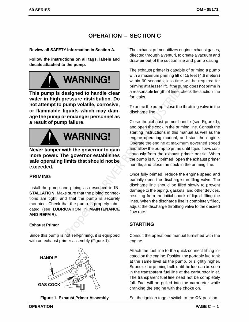
Exhaust Primer
Since this pump is not self-priming, it is equippedwith an exhaust primer assembly (Figure 1).
HANDLE
GAS COCK
Figure 1. Exhaust Primer Assembly
The exhaust primer utilizes engine exhaust gases,directed through a venturi, to create a vacuum anddraw air out of the suction line and pump casing.
The exhaust primer is capable of priming a pumpwith a maximum priming lift of 15 feet (4,6 meters)within 90 seconds; less time will be required forpriming at a lesser lift. If the pump does not prime ina reasonable length of time, check the suction linefor leaks.
To prime the pump, close the throttling valve in thedischarge line.
Close the exhaust primer handle (see Figure 1),and open the cock in the priming line. Consult thestarting instructions in this manual as well as theengine operating manual, and start the engine.Operate the engine at maximum governed speedand allow the pump to prime until liquid flows con-tinuously from the exhaust primer nozzle. Whenthe pump is fully primed, open the exhaust primerhandle, and close the cock in the priming line.
Once fully primed, reduce the engine speed andpartially open the discharge throttling valve. Thedischarge line should be filled slowly to preventdamage to the piping, gaskets, and other devices,resulting from the initial shock of liquid filling thelines. When the discharge line is completely filled,adjust the discharge throttling valve to the desiredflow rate.
STARTING
Consult the operations manual furnished with theengine.
Attach the fuel line to the quick-connect fitting lo-cated on the engine. Position the portable fuel tankat the same level as the pump, or slightly higher.Squeeze the priming bulb until the fuel can be seenin the transparent fuel line at the carburetor inlet.The transparent fuel line need not be completelyfull. Fuel will be pulled into the carburetor whilecranking the engine with the choke on.
Set the ignition toggle switch to the ON position.
60 SERIESOM--05171
OPERATIONPAGE C -- 2
Set the twist-lock throttle control at approximatelyhalf open position. Start the engine and follow en-gine manufacturer’s recommendations for carbu-retor adjustments to obtain optimum performance.
NOTEHard starting may be experienced after connectinga new tank of fuel. This can be caused by airtrapped in the fuel line. It is recommended that thefuel line be vented and filled by depressing thevalve in the female quick connect fitting prior toinstalling it on the pump.
OPERATION
Pump speed and operating conditionpoints must be within the continuous per-formance range shown on the curve. (SeeSection E, Page 1.)
Leakage
No leakage should be visible at pump mating sur-faces, or at pump connections or fittings. Keep allline connections and fittings tight to maintain maxi-mum pump efficiency.
Liquid Temperature And Overheating
The maximum liquid temperature for this pump is160_F (71_C). Do not apply it at a higher operatingtemperature than is recommended.
Overheating can occur if operated with the valvesin the suction or discharge lines closed. Operatingagainst closed valves could bring the liquid to aboil, build pressure, and cause the pump to rup-ture or explode. If overheating occurs, stop thepump and allow it to completely cool before servic-ing it. Refill the pump casing with cool liquid.
Do not remove plates, covers, gauges,pipe plugs, or fittings from an over-
heated pump. Vapor pressure within thepump can cause parts being disen-gaged to be ejected with great force. Al-low the pump to completely cool beforeservicing.
Strainer Check
If a suction strainer has been shipped with thepump or installed by the user, check the strainerregularly, and clean it as necessary. The strainershould also be checked if pump flow rate begins todrop. If a vacuum suction gauge has been in-stalled, monitor and record the readings regularlyto detect strainer blockage.
Never introduce air or steam pressure into thepump casing or piping to remove a blockage. Thiscould result in personal injury or damage to theequipment. If backflushing is absolutely neces-sary, liquid pressure must be limited to 50% of themaximum permissible operating pressure shownon the pump performance curve. (See Section E,Page 1.)
Pump Vacuum Check
With the pump inoperative, install a vacuum gaugein the system, using pipe dope on the threads.Block the suction line and start the pump. At oper-ating speed the pump should pull a vacuum of 20inches (508,0 mm) or more of mercury. If it doesnot, check for air leaks in the seal, gasket, or dis-charge valve.
Open the suction line, and read the vacuum gaugewith the pump primed and at operation speed.Shut off the pump. The vacuum gauge reading willimmediately drop proportionate to static suctionlift, and should then stabilize. If the vacuum readingfalls off rapidly after stabilization, an air leak exists.Before checking for the source of the leak, checkthe point of installation of the vacuum gauge.
STOPPING
Never halt the flow of liquid suddenly. If the liquidbeing pumped is stopped abruptly, damagingshock waves can be transmitted to the pump andpiping system. Close all connecting valves slowly.

60 SERIES OM--05171
OPERATION PAGE C -- 3
If the application involves a high dischargehead, gradually close the dischargethrottling valve before stopping the pump.After stopping the pump, switch off the engine igni-tion and remove or ground the spark plug to en-sure that the pump will remain inoperative.
Cold Weather Preservation
In below freezing conditions, drain the pump to
prevent damage from freezing. Also, clean out anysolids by flushing with a hose. Operate the pumpfor approximately one minute; this will remove anyremaining liquid that could freeze the pump rotat-ing parts. If the pump will be idle for more than afew hours, or if it has been pumping liquids con-taining a large amount of solids, drain the pump,and flush it thoroughly with clean water. To preventlarge solids from clogging the drain port and pre-venting the pump from completely draining, inserta rod or stiff wire in the drain port, and agitate theliquid during the draining process. Clean out anyremaining solids by flushing with a hose.

60 SERIES OM--05171
TROUBLESHOOTING PAGE D -- 1
TROUBLESHOOTING --- SECTION D
Review all SAFETY information in Section A.
Before attempting to open or service thepump:
1. Familiarize yourself with this man-ual.
2. Shutdown the engine and removethe spark plug wires to ensure thatthe pump will remain inoperative.
3. Allow the pump to completely coolif overheated.
4. Vent the pump slowly and cau-tiously.
5. Close the suction and dischargevalves.
6. Check the temperature beforeopening any covers, plates, orplugs.
7. Drain the pump.For specific instructions on engine troubleshootingor repair, see the engine manual.
Table B-1 Troubleshooting Chart
TROUBLE CAUSE REMEDY
ENGINE FAILS TOSTART
Auxiliary priming device faultyor improperly installed.
Integral discharge checkvalve clogged or binding.
Spark plug contaminated.
No fuel to engine or fuel con-taminated.
Engine flooded.
Repair priming device or check installation.
Clean valve.
Clean and replace plug; reset gap.
Check fuel tank level; vent tank; purge airfrom fuel lie; clean fuel filters. Check fuel forproper oil mix; check for contamination.
Dry spark plug; adjust carburetor; see enginemanual.
PUMP FAILS TOPRIME
Auxiliary priming device faultyor improperly installed.
Integral discharge checkvalve clogged or binding.
Air leak in suction line.
Lining of suction hose col-lapsed.
Leaking or worn seal or pumpgasket.
Suction lift or discharge headto high.
Strainer clogged.
Repair priming device or check installation.
Clean valve.
Correct leak.
Replace suction hose.
Check pump vacuum. Replace leaking orworn seal or gasket.
Check piping installation and reduce suctionlift and/or discharge head.
Check strainer and clean if necessary.

OM--05171 60 SERIES
TROUBLESHOOTINGPAGE D -- 2
Table B-1 Troubleshooting Chart (continued)
TROUBLE CAUSE REMEDY
PUMP STOPS ORFAILS TO DELIVERRATED FLOW ORPRESSURE
Air leak in suction line.
Suction intake not submergedat proper level or sump toosmall.
Lining of suction hose col-lapsed.
Discharge line clogged or re-stricted; hose kinked.
Impeller or other wearing partsworn or damaged.
Impeller clogged.
Pump speed too slow.
Suction lift or discharge headto high.
Leaking or worn seal or pumpgasket.
Correct leak.
Check installation and correct submergence asneeded.
Replace suction hose.
Check discharge lines; straighten hose.
Replace worn or damaged parts. Check thatimpeller is properly centered and rotates freely.
Free impeller of debris.
Check engine output; consult engine operationmanual.
Check piping installation and reduce suction liftand/or discharge head.
Check pump vacuum. Replace leaking or wornseal or gasket.
PUMP REQUIRESTOO MUCH POWER
Exceeding operating limits.
Liquid solution too thick.
See performance curve in Pump MaintenanceAnd Repair.
Dilute if possible.
PREVENTIVE MAINTENANCE
Since pump applications are seldom identical, andpump wear is directly affected by such things asthe abrasive qualities, pressure and temperatureof the liquid being pumped, this section is intendedonly to provide general recommendations andpractices for preventive maintenance. Regardlessof the application however, following a routine pre-ventive maintenance schedule will help assuretrouble-free performance and long life from yourGorman-Rupp pump. For specific questions con-cerning your application, contact your Gorman-Rupp distributor or the Gorman-Rupp Company.
Record keeping is an essential component of agood preventive maintenance program. Changesin suction and discharge gauge readings (if so
equipped) between regularly scheduled inspec-tions can indicate problems that can be correctedbefore system damage or catastrophic failure oc-curs. The appearance of wearing parts should alsobe documented at each inspection for comparisonas well. Also, if records indicate that a certain part(such as the seal) fails at approximately the sameduty cycle, the part can be checked and replacedbefore failure occurs, reducing unscheduled downtime.
For new applications, a first inspection of wearingparts at 250 hours will give insight into the wear ratefor your particular application. Subsequent inspec-tions should be performed at the intervals shownon the chart below. Critical applications should beinspected more frequently.

60 SERIES OM--05171
TROUBLESHOOTING PAGE D -- 3
General Condition (Temperature, UnusualNoises or Vibrations, Cracks, Leaks,Loose Hardware, Etc.) I
Pump Performance (Gauges, Speed, Flow) IBearing Lubrication I RSeal Lubrication (And Packing Adjustment,
If So Equipped) I RV-Belts (If So Equipped) IAir Release Valve Plunger Rod (If So Equipped) I CFront Impeller Clearance (Wear Plate) IRear Impeller Clearance (Seal Plate) ICheck Valve IPressure Relief Valve (If So Equipped) CPump and Driver Alignment IShaft Deflection IBearings IBearing Housing IPiping IDriver Lubrication --- See Mfgr’s Literature
Legend:I = Inspect, Clean, Adjust, Repair or Replace as Necessary
C = CleanR = Replace* Service interval based on an intermittent duty cycle equal to approximately 4000 hours annually.
Adjust schedule as required for lower or higher duty cycles or extreme operating conditions.
Preventive Maintenance Schedule
Item Daily Weekly Monthly Semi-Annually
Annually
Service Interval*
OM--0517160 SERIES
MAINTENANCE & REPAIR PAGE E -- 1
PUMP MAINTENANCE AND REPAIR --- SECTION E
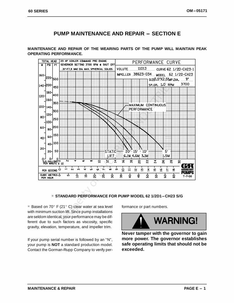
MAINTENANCE AND REPAIR OF THE WEARING PARTS OF THE PUMP WILL MAINTAIN PEAKOPERATING PERFORMANCE.
STANDARD PERFORMANCE FOR PUMP MODEL 62 1/2D1--CH23 S/G
Based on 70_ F (21_ C) clear water at sea levelwith minimum suction lift. Since pump installationsare seldom identical, your performance may be dif-ferent due to such factors as viscosity, specificgravity, elevation, temperature, and impeller trim.
If your pump serial number is followed by an “N”,your pump is NOT a standard production model.Contact the Gorman-Rupp Company to verify per-
formance or part numbers.
Never tamper with the governor to gainmore power. The governor establishessafe operating limits that should not beexceeded.

60 SERIESOM--05171
MAINTENANCE & REPAIRPAGE E -- 2
SECTION DRAWING
Figure 1. Pump Model 62 1/D1---CH23 S/G

ITEMNO.
PART NAME PARTNUMBER
MAT’LCODE
QTY ITEMNO.
PART NAME PARTNUMBER
MAT’LCODE
QTY
OM--0517160 SERIES
MAINTENANCE & REPAIR PAGE E -- 3
PARTS LISTPump Model 62 1/2D1---CH23 S/G
(From S/N 1211015 up)
If your pump serial number is followed by an “N”, your pump is NOT a standard production model. Contactthe Gorman-Rupp Company to verify part numbers.
1 PUMP END ASSY 62 1/2D1--- (CH23) 12 KOHLER CH23PS ENGINE 29127---303 --- --- --- 13 ROLLOVER BASE 41583---344 24150 14 MUFFLER ASSY 46211---029 24150 15 MUFFLER GUARD KIT 29187---111 --- --- --- 16 PRESSURE GAUGE S180 --- --- --- 17 HAND CARRY DECAL 2613FT --- --- --- 28 DISCHARGE STICKER 6588BJ --- --- --- 19 SUCTION STICKER 6588AG --- --- --- 1
10 COUPLING 2469 14000 211 EXHAUST PRIMER ASSY 46112---706 --- --- --- 112 WARNING DECAL 2613FE --- --- --- 113 BRACKET 34144---036 15080 114 FLAT WASHER K06 15991 115 HEX HD CAPSCREW B0603 15991 116 HEX NUT D06 15991 117 DISCONNECT BUSHING 26534---082 --- --- --- 118 DUST CAP 26531---301 --- --- --- 119 JAM NUT AT06S 15991 120 FUEL LINE 11308H --- --- --- 121 HOSE CLAMP S1788 --- --- --- 222 HEX HD CAPSCREW B0606 15991 423 FLAT WASHER K06 15991 424 FLANGED HEX NUT 21765---314 --- --- --- 425 STUD C0709 15991 426 HEX NUT D07 15991 427 LOCKWASHER J07 15991 4
28 RUBBER FOOT MTG KIT 48152---603 --- --- --- 129 ---RUBBER BUMPER S1224 --- --- --- 430 ---HEX HD CAPSCREW B0504 15991 431 ---FLAT WASHER K05 15991 432 ---FLANGED HEX NUT 21765---312 --- --- --- 433 NAME PLATE 2613BF 13990 134 DRIVE SCREW BM#04---03 17000 435 BATTERY BOX ASSY GRP40---05 --- --- --- 136 ---HEX HD CAPSCREW B0503 15991 437 ---T TYPE LOCKWASHER BL05 15991 138 ---FLANGED HEX NUT 21765---312 --- --- --- 439 ---BATTERY BOX 11281 24000 140 ---BATTERY S1680 --- --- --- REF41 ---BATTERY TAG 38818---680 --- --- --- 142 ---BATTERY BOX COVER 11870 24000 143 ---HEX HD CAPSCREW B0504 15991 244 ---FLANGED HEX NUT 21765---312 --- --- --- 245 ---GROUND CABLE 47311---542 --- --- --- 146 ---POS BATTERY CABLE 47311---502 --- --- --- 147 FUEL TANK ASSY 46711---086 --- --- --- 1
NOT SHOWN:STRAINER 26841---010 --- --- --- 1ADAPTOR 26115---011 --- --- --- 1EXHAUST PRIMER TAG 6588X --- --- --- 1INSTRUCTION TAG 38817---045 --- --- --- 1ENG START---UP TAG 38816---269 --- --- --- 1
INDICATES PARTS RECOMMENDED FOR STOCK

60 SERIESOM--05171
MAINTENANCE & REPAIRPAGE E -- 4
SECTION DRAWING
Figure 2. 62 1/2D1---(CH23) Pump End Assembly
OM--0517160 SERIES
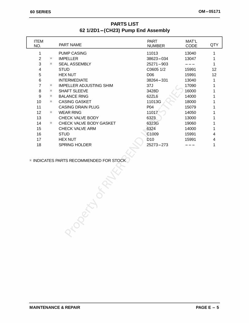
MAINTENANCE & REPAIR PAGE E -- 5
PARTS LIST62 1/2D1---(CH23) Pump End Assembly
ITEMNO. PART NAME
PARTNUMBER
MAT’LCODE QTY
1 PUMP CASING 11013 13040 12 IMPELLER 38623---034 13047 13 SEAL ASSEMBLY 25271---903 --- --- --- 14 STUD C0605 1/2 15991 125 HEX NUT D06 15991 126 INTERMEDIATE 38264---331 13040 17 IMPELLER ADJUSTING SHIM 37J 17090 18 SHAFT SLEEVE 3428D 16000 19 BALANCE RING 62ZL6 14000 1
10 CASING GASKET 11013G 18000 111 CASING DRAIN PLUG P04 15079 112 WEAR RING 11017 14050 113 CHECK VALVE BODY 6323 13000 114 CHECK VALVE BODY GASKET 6323G 19060 115 CHECK VALVE ARM 6324 14000 116 STUD C1009 15991 417 HEX NUT D10 15991 418 SPRING HOLDER 25273---273 --- --- --- 1
INDICATES PARTS RECOMMENDED FOR STOCK
60 SERIESOM--05171
MAINTENANCE & REPAIRPAGE E -- 6
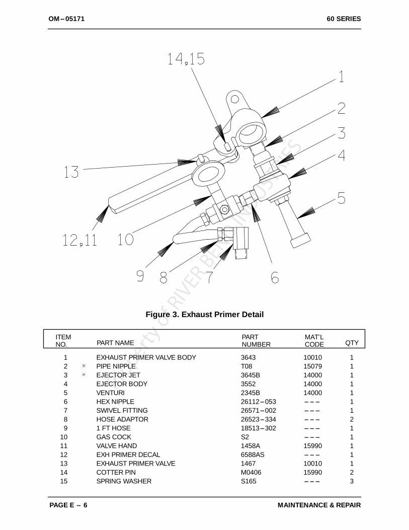
Figure 3. Exhaust Primer Detail
ITEMNO. PART NAME
PARTNUMBER
MAT’LCODE QTY
1 EXHAUST PRIMER VALVE BODY 3643 10010 12 PIPE NIPPLE T08 15079 13 EJECTOR JET 3645B 14000 14 EJECTOR BODY 3552 14000 15 VENTURI 2345B 14000 16 HEX NIPPLE 26112---053 --- --- --- 17 SWIVEL FITTING 26571---002 --- --- --- 18 HOSE ADAPTOR 26523---334 --- --- --- 29 1 FT HOSE 18513---302 --- --- --- 1
10 GAS COCK S2 --- --- --- 111 VALVE HAND 1458A 15990 112 EXH PRIMER DECAL 6588AS --- --- --- 113 EXHAUST PRIMER VALVE 1467 10010 114 COTTER PIN M0406 15990 215 SPRING WASHER S165 --- --- --- 3

OM--0517160 SERIES
MAINTENANCE & REPAIR PAGE E -- 7
PUMP AND SEAL DISASSEMBLYAND REASSEMBLY
Review all SAFETY information in Section A.
Follow the instructions on all tags, label and de-cals attached to the pump.
This pump requires little service due to its rugged,minimum-maintenance design. However, if it be-comes necessary to inspect or replace the wearingparts, follow these instructions which are keyed tothe sectional view (see Figure 1) and the accompa-nying parts list.
Most service functions, such as wear plate, impel-ler, and seal replacement, may be performed bydraining the pump and removing the back coverassembly. However, the following instructions as-sume complete disassembly is required.
As described in the SAFETY Section, this manualwill alert personnel to known procedures which re-quire special attention, to those which could dam-age equipment, and to those which could be dan-gerous to personnel. However, this manual cannotpossibly anticipate and provide detailed precau-tions for every situation that might occur duringmaintenance of the unit. Therefore, it is the respon-sibility of the owner/maintenance personnel to en-sure that only safe, established shop proceduresare used, and that any procedures not addressedin this manual are performed only after establish-ing that neither personal safety nor pump integrityare compromised by such practices.
Before attempting to service the pump, switch offthe engine ignition and remove the spark plug, ortake other precautions to ensure that it will remaininoperative. Close all valves in the suction and dis-charge lines.
For engine disassembly and repair, consult the lit-erature supplied with the engine, or contact yourlocal Kohler engine representative.
Before attempting to open or service thepump:
1. Familiarize yourself with this man-ual.
2. Shut down the engine and removethe spark plug wires to ensure thatthe pump will remain inoperative.
3. Allow the pump to completely coolif overheated.
4. Check the temperature beforeopening any covers, plates, orplugs.
5. Close the suction and dischargevalves.
6. Vent the pump slowly and cau-tiously.
7. Drain the pump.Discharge Check Valve Disassembly
(Figure 2)
Remove the nuts (17) and separate the check valvebody (13) from the pump casing (1). Pull the rubbergasket (14) from the flange studs (16), and pull thecheck valve arm (15) from the check valve body.Unscrew the pressure gauge and fire hose adaptorif required.
Clean the mating surfaces of both flanges and in-spect all parts for wear or damage. If no further dis-assembly is required, refer to Discharge CheckValve Reassembly.
Exhaust Primer Disassembly
(Figure 3)
Remove the hose adaptor (8) from the swivel fitting(7). If necessary, remove the gas cock valve (10)and pipe nipple (6).
To remove the exhaust primer body (1) unscrewthe body from the muffler (4). To disassemble theexhaust primer, remove the handle (11) and un-screw the various primer components.
If no further disassembly is required, refer to Ex-haust Primer Reassembly.
Pump Disassembly
(Figure 2)
After disconnecting the exhaust primer, removethe casing drain plug (11) and drain the pump cas-ing. Clean and reinstall the plug.
For access to the impeller (2) and seal assembly(3), remove the nuts (5) securing the pump casingto the intermediate (6). Remove the casing gasket(10) and clean the contacting surfaces.
60 SERIESOM--05171
MAINTENANCE & REPAIRPAGE E -- 8
Inspect the wear ring (12) for excessive wear ordamage. The wear ring is secured in the pump cas-ing by a press fit. If replacement is required, use asmall bit to drill two holes horizontally through thering, 180_ apart. Use a chisel or other suitable toolto complete the cuts through the ring and removethe ring from the casing. Be careful not to damagethe casing bore when removing the ring.
To remove the impeller, insert a steel bar or drift pinbetween the vanes, and turn the impeller in acounter-clockwise direction (when facing the im-peller) while holding the engine crankshaft station-ary. Be careful not to damage the impeller vanes.Use caution when unscrewing the impeller; ten-sion on the seal spring will be released as the im-peller is removed.
Inspect the balance ring (9) for excessive wear ordamage. The balance ring is secured in the inter-mediate by a press fit. If replacement is required,use a small bit to drill two holes horizontallythrough the ring, 180_ apart. Use a chisel or othersuitable tool to complete the cuts through the ringand remove the ring from the intermediate. Becareful not to damage the intermediate bore whenremoving the ring.
Seal Removal and Disassembly
(Figure 2 And 4)
Remove the spring holder (18) and the impeller ad-justing shims (7). Tie and tag the shims or measureand record their thickness for ease of reassembly.
Remove the seal spring, then slide the shaft sleeveand rotating portion of the seal off the engine shaftas a unit. Apply oil to the sleeve and work it up un-der the bellows. Slide the rotating portion of theseal off the sleeve. Use two stiff wires with hookedends to pull the stationary seat from the intermedi-ate bore.
NOTEAn alternate method of removing the stationary seatis to remove the hardware (26 and 27, Figure 1) andseparate the intermediate from the engine. Use adowel to press the stationary seat from the inter-mediate.
If no further disassembly is required, refer to SealReassembly And Installation.
Seal Reassembly and Installation
(Figure 2 And 4)
Clean the seal cavity and shaft with a cloth soakedin fresh cleaning solvent.
Most cleaning solvents are toxic andflammable. Use them only in a well ven-tilated area free from excessive heat,sparks, and flame. Read and follow allprecautions printed on solvent contain-ers.
The seal is not normally reused because wear pat-terns on the finished faces cannot be realignedduring reassembly. This could result in prematurefailure. If necessary to reuse an old seal in an emer-gency, carefully wash all metallic parts in freshcleaning solvent and allow to dry thoroughly.
Handle the seal parts with extreme care to preventdamage. Be careful not to contaminate precisionfinished faces; even fingerprints on the faces canshorten seal life. If necessary, clean the faces with anon-oil based solvent and a clean, lint-free tissue.Wipe lightly in a concentric pattern to avoidscratching the faces.
Inspect the seal components for wear, scoring,grooves, and other damage that might cause leak-age. Clean and polish the shaft sleeve, or replace itif there are cuts or nicks on either end. If any com-ponents are worn, replace the complete seal;never mix old and new seal parts.
If a replacement seal is being used, remove it fromthe container and inspect the precision finishedfaces to ensure that they are free of any foreignmatter.
To ease installation of the seal, lubricate the rotat-ing element O-ring with water or a very smallamount of oil, and apply a drop of light lubricatingoil on the finished faces. Assemble the seal as fol-lows, (see Figure 4).

OM--0517160 SERIES
MAINTENANCE & REPAIR PAGE E -- 9
IMPELLER
IMPELLERSHAFT
O-RINGRETAINER
BELLOWS
SPRINGROTATINGELEMENT
STATIONARYELEMENT
INTERMEDIATE
IMPELLERSHIM SET
SHAFTSLEEVE
Figure 4. 25271--903 Seal Assembly
This seal is not designed for operation attemperatures above 160_F (71_C). Do notuse at higher operating temperatures.
If the balance ring (9) was removed, the replace-ment ring should be pressed into the intermediatebefore installing the seal. Position the ring in the in-termediate bore with the chamfered end toward to-ward the bore shoulder and press it into the boreuntil fully seated.
NOTEThe balance ring must be fully seated in the inter-mediate bore, otherwise binding and/or excessivewear could result.
If the intermediate was removed, lay it on a flat sur-face with the impeller side facing up.
Lubricate the stationary seat O-ring with light oiland install it in the stationary seat. Use thumb pres-sure to press this subassembly into the intermedi-ate bore until fully seated. Be careful not todamagethe seal face. After installation, wipe the seal face ina concentric pattern with a clean, lint-free cloth toremove any fingerprints.
Secure the intermediate to the engine with thehardware (26 and 27). Be careful not to damagethe stationary seat on the shaft threads.
Slide the rotating portion of the seal (consisting ofthe retainer, bellows and rotating element) onto thesleeve (8) until the rotating face is just flush withthe chamfered end of the sleeve. Slide the sleeveonto the shaft until the seal faces contact. Continueto push the sleeve through the seal until it seatsagainst the shaft shoulder.
Install the seal spring. Make sure that all compo-nents of the seal are seated squarely.

60 SERIESOM--05171
MAINTENANCE & REPAIRPAGE E -- 10
Impeller Installation
(Figures 2 and 5)
Inspect the impeller (2), and replace it if cracked orbadly worn.
For maximum pump efficiency, the impeller mustbe centered within the volute scroll. To verify impel-ler positioning, measure the pump casing and im-peller as shown in Figure 5. Use these measure-ments to calculate the required impeller location(dimension E). Add or remove impeller adjustingshims (55) to obtain dimension E.
D
B2
A B
2
C D
E
Step 2Step 1 Step 3
A+ B2 C+ D
2E=---
Figure 5. Centering Impeller Within Pump Casing
NOTEAfter the impeller has been properly positioned,check for free rotation. Correct any scraping orbinding before further reassembly.
Pump Reassembly
(Figure 2)
If the wear ring (12) was removed, apply ‘LoctiteNo. 242 Threadlocker’ or equivalent compound)between the casing and the wear ring. Position thereplacement ring in the casing bore so that cham-fer on the I.D. faces toward the impeller. Press thering into the bore until fully seated against the cas-ing shoulder.
NOTEThe wear ring must be fully seated in the casingbore, otherwise binding and/or excessive wearcould result.
Install the pump casing gasket (10). Carefullyguide the wear ring into the eye of the impeller, andsecure the casing to the intermediate with the nuts(5).
NOTEAfter the pump casing has been install check theimpeller for free rotation. Correct any scraping orbinding before further reassembly.
Exhaust Primer Reassembly
(Figure 3)
NOTEBefore assembly, apply pipe sealant on allthreaded joints.
To install the exhaust primer body (1) screw thebody into the muffler (4). To assemble the exhaustprimer, install the handle (11) and install the variousprimer components.
Screw the hose adaptor (8) into the swivel fitting(7). Install the gas cock valve (10) and pipe nipple(6).

OM--0517160 SERIES
MAINTENANCE & REPAIR PAGE E -- 11
Discharge Check Valve Reassembly
(Figure 2)
Position the pivot of the check valve arm (15) in theslot in the valve body (13). Install the rubber gasket(14), and secure the assembly to the casing withthe nuts (17). Check for free operation of the valvearm. Inspect the pressure gauge and hose adaptorfor wear or damage before installation and replaceas required.
LUBRICATION
Seal Assembly
(Figure 2)
The seal assembly is lubricated by the medium be-ing pumped. No addition lubrication is required.
Engine
(Figure 1)
Refer to the literature provided with the engine, orcontact your local Kohler engine representative.

THE GORMAN-RUPP COMPANY F MANSFIELD, OHIOGORMAN-RUPP OF CANADA LIMITED DST. THOMAS, ONTARIO, CANADA Printed in U.S.A.
July 18, 1979
WARRANTY
Pumping units manufactured by The Gorman-Rupp Company,Mansfield, Ohio are guaranteed to be free from defects in mate-rial and workmanship for one year from date of shipment fromfactory in Mansfield, Ohio. The obligation under this Warranty,statutory or otherwise, is limited to replacement or repair atMansfield, Ohio factory or at a point designated by Gorman-Rupp, of such part as shall appear to us upon inspection at suchpoint, to have been defective in material or workmanship.
This Warranty does not obligate The Gorman-Rupp Company tobear the cost of labor or transportation charges in connectionwith replacement or repair of defective parts; nor shall it apply toa pump upon which repairs or alterations have been made un-less authorized by Gorman-Rupp.
No warranty is made in respect to engines, motors, or trade ac-cessories, such being subject to warranties of their respectivemanufacturers.
In Submersible Pumps, pump and motor are integral and Sub-mersibles are warranted as a unit. Since motor is subject to animportant degree upon quality and performance of electricalcontrols, unit warranty is valid only when controls have beenspecified and provided by Gorman-Rupp.
No express implied or statutory warranty, other than herein setforth is made or authorized to be made by Gorman-Rupp.
In no event shall The Gorman-Rupp Company be liable for con-sequential damages or contingent liabilities arising out of the fail-ure of any Gorman-Rupp pump or parts thereof to operate prop-erly.
THE GORMAN-RUPP COMPANY
Mansfield, Ohio
NOTE: In Canada, all above references to “The Gorman-RuppCompany, Mansfield, Ohio” is understood to mean “Gorman-Rupp of Canada Limited, St. Thomas, Ontario.”
ECopyright by the Gorman-Rupp Company