installation, operation & maintenance · pdf filesw oil fired direct exhaust. cast iron...
TRANSCRIPT

SWOIL FIRED DIRECT EXHAUST
CAST IRON BOILER
INSTALLATION, OPERATION & MAINTENANCE MANUAL
P/N# 27515401, Rev. A [03/2011]An ISO 9001-2008 Certified Company
Utica Boilers2210 Dwyer Avenue, Utica NY 13504-4729Phone: (315) 797-1310 • Fax: (866) 432-7329e-mail: [email protected] site: www.ecrinternational.com

2
Tested For 75 psig.ASME Working Pressure
tABLE OF CONtENtS
Safety Symbols ........................................................................................................................... 3
Installation ................................................................................................................................ 4
Connecting Supply And Return Piping ............................................................................................. 5
Recommended Piping For Boilers Equipped With A P3 Or T4 Tankless Heater ........................................ 9
Options Utilizing 3/4" Tapping ......................................................................................................10
Oil Tank And Piping .....................................................................................................................11
Electrical Wiring .........................................................................................................................12
Thermostat Installation ...............................................................................................................13
Normal Sequence Of Operation .....................................................................................................14
Operating Instructions .................................................................................................................14
Instructions To Obtain Proper Operation Of The Boiler-Burner Unit ....................................................15
Preventive Maintenance ...............................................................................................................16
Instructions For Opening And Closing Burner Swing Door .................................................................16
Service Check List ......................................................................................................................17
Sw Series Replacement Parts .......................................................................................................18
Dimensions ................................................................................................................................26
Read All Instructions Before Installing.

3
Safety SymbolsThe following defined symbols are used throughout this manual to notify the reader of potential hazards of varying risk levels.
SAFEty SymBOLS
!
WARNING
Keep boiler area clear and free from • combustible materials, gasoline and other flammable vapors and liquids.
DO NOT obstruct air openings to boiler • room.
Modification, substitution or elimination • of factory equipped, supplied or specified components may result in property damage, personal injury or the loss of life.
!
WARNING
Boiler and venting installations should be done only by a qualified expert and in accordance with the appropriate Utica Boilers Installation, Operation and Maintenance manual. Installing or venting a boiler or any other gas appliance with improper methods or materials may result in serious injury or death due to fire or to asphyxiation from poisonous gases such as carbon monoxide which is odorless and invisible.
! DANGER
Indicates a hazardous situation which, if not avoided, WILL result in death or serious injury.
! CAUTION
Indicates a hazardous situation which, if not avoided, may result in minor or moderate injury.
! WARNING
Indicates a hazardous situation which, if not avoided, could result in death or serious injury.
NOTICE
Indicates information which should be followed to ensure proper installation and operation. NOTICE
To the owner: Installation and service of • this boiler must be performed by a qualified installer.
To the installer: Leave all instructions with • the boiler for future reference.
When this product is installed in the • Commonwealth of Massachusetts installation must be performed by a Licensed Plumber or Licensed Gas Fitter.

4
InstallationInstallation must conform to American Society of Mechanical Engineers Safety Code for Controls and Safety Devices for Automatically Fired Boilers, ANSI/ASME CSD-1. In Canada installations must be in accordance with CSA B139. In absence of such codes, installation must conform to the requirements of authority having jurisdiction. Such applicable requirements take precedence over general instructions of this manual.
Locate boiler in front of final position before removing crate. Provide level solid base as near to vent outlet as possible and centrally located with respect to heat distribution system as practical.
Allow 24 inches in front and top for servicing and cleaning, or removing tankless water heating coil.
When installed in utility room, door should be wide enough to allow largest boiler part to enter, or permit replacement of another appliance such as water heater.
Installation on Combustible FloorsBoiler shall not be installed directly on carpeting, tile or other combustible material other than wood flooring. Boiler must not be installed on carpeting or vinyl flooring.
INStALLAtION
! WARNING
Improper installation, adjustment, alteration, service or maintenance could result in personal injury or loss of life.
Minimum clearances to combustible construction are:
TOP ..............................................0.0 IN. FRONT ..................................... 24.0 IN.* FLUE CONNECTOR .......................... 2.0 IN. REAR ............................................0.0 IN. LEFT SIDE .....................................0.0 IN. RIGHT SIDE ...................................0.0 IN.
* "FOR ALCOVE INSTALLATION"
Recommended clearance for service access should exceed fire protection clearance.
TOP ...............................................24 IN. FRONT ...........................................24 IN. FLUE CONNECTOR .............................9 IN. REAR ...............................................6 IN. LEFT SIDE ......................................10 IN. RIGHT SIDE ......................................6 IN.
Remove crate and plastic protective wrapper and inspect for damage. Our responsibility ceases upon delivery of the crated boiler to the carrier in good condition. Any claims for damage or shortage in shipment must be filed immediately against carrier by consignee. Move boiler to permanent position by sliding or walking.

5
CONNECtINg SuppLy ANd REtuRN pIpINg
NOTICE
Circulators in following illustrations are mounted on system supply side, mounting on system return side is also acceptable practice.
Figure 1 - Typical Installation Using Circulators
Figure 2 - Typical Installation Using Zone Valves

6
Typical installation using circulators shown in 1. Figure 1.
Typical installation using zone valves shown in 2. Figure 2.
Hot water boilers installed above radiation level must 3. be provided with low water device either as part of boiler or at time of boiler installation.
When boiler is connected to heating system utilizing 4. multiple zoned circulators, each circulator must be supplied with flow control valve to prevent gravity circulation.
Reduced pressure back flow preventer must be • present under provisions required by Environmental Protection Agency, (EPA).
Bypass piping is an option which gives ability to adjust 5. supply boiler water temperature to fit system or condition of installation. This method of piping is not typically required for baseboard heating systems.
CONNECtINg SuppLy ANd REtuRN pIpINg
Method used to protect systems using radiant • panels and material they are encased in from high temperature supply water from boiler. See Figure 3.
Method used to protect boilers from condensate • forming due to low temperature return water. Generally noticed in large converted gravity systems or other large water volume systems. See Figure 4.
Method used to protect boilers from condensate • forming as well as protecting heating system from high water temperature. See Figure 5.
When using bypass piping, adjust valves A and B until 6. desired system temperature is obtained.
Bypass loop piping must be same size piping for supply 7. and return.
WITHIN 6"
Figure 3

7
CONNECtINg SuppLy ANd REtuRN pIpINg
Figure 4
Figure 5

8
CONNECtINg SuppLy ANd REtuRN pIpINg
Connect supply and return piping as suggested in 8. Figure 6, when boiler is used in connection with refrigerated systems:
Chilled medium must be in parallel with the boiler.A.
Use appropriate valves to prevent chilled medium B. from entering heating boiler.
During heating cycle open valves A and B, close valves 9. C and D.
During heating cooling cycle open valves C and D, close 10. valves A and B.
Maintain minimum clearance of one inch to hot A. water pipes.
In air handling units where they may be exposed to refrigerated air circulation, boiler piping system MUST be supplied with flow control valves or other automatic means to prevent gravity circulation of boiler water during cooling cycle.
For further piping information refer to the I=B=R 11. installation and piping guide.
Figure 6

9
RECOmmENdEd pIpINg FOR BOILERS EquIppEd WIth A p3 OR t4 tANkLESS hEAtER
! DANGER
Burn, scald hazard. Water temperatures exceeding 125º F will cause severe burns instantly or death by scalding.
An automatic mixing valve must be installed on the • outlet of the domestic coil. Installation must comply with the valve manufacture’s recommendations, and instructions.
Do not remove the bolts or aquastat at the time of • installation.
Pipe in accordance with the installation manual.•
Due to varying water conditions, an adjustable flow • restrictor must be installed in the cold water inlet of this coil.
Figure 7 Recommended Piping For Boilers Equipped With A P3 Or T4 Tankless Heater

10
OptIONS utILIzINg 3/4" tAppINg
Figure 8 - Optional Location For Air Vent
Figure 9 - Optional Location For Expansion Tank (Non-Diaphragm Type)

11
Install Oil tank and piping in accordance with the National Board of Fire Underwriters and in absence of such regulations in accordance with authority having jurisdiction. Oil storage tank, vent, fill pipe and caps should be in accordance with the authority having jurisdiction.
In no case should vent pipe be smaller than 1-1/4" A. I.P.S.
Fill pipe should not be less than 2" I.P.S.B.
Suction line from tank to burner should be one • continuous piece of tubing to prevent air entering line. Suction line, must be 3/8" O.D. copper tubing for runs of 50 feet or less, and 1/2" O.D. for longer runs.
Oil return line, same size as suction line, must be used • on any installation where bottom of tank is below fuel unit of burner.
Oil lines should be buried or otherwise protected from • mechanical injury.
Flare fittings on all oil lines are recommended. •
Compression fittings on suction line often allow air to • be drawn into fuel pump, making it difficult to maintain oil pressure at nozzle.
OIL tANk ANd pIpINg
Do not run overhead fuel lines from tank to oil burner.•
Fuel pump connections and by-pass should be made • according to instructions attached to fuel pump. If tank is more than 20' from the boiler, a two stage fuel unit should be installed in place of single stage pump supplied as standard equipment with burner. Make certain rotation and speed are same and pump is suitable for burner horsepower rating. Oil line filter and shut-off valve should be installed in • suction line.
Shut-off valves should be installed in both suction • and return lines at burner for convenience in servicing burner.
Allow extra tubing at burner so burner may be removed • from boiler for cleaning without disconnecting tubing. (See Figures 10 & 11).
A UL approved flexible oil line may be used.•
Figure 10 - Typical Installation Single Pipe Oil System
Figure 11 - Typical Installation Two Pipe Oil System

12
Electrical wiring must conform with National Electrical Code ANSI/NFPA No. 70 in United States and CSA C22.1 Canadian Electrical Code in Canada and/or the local authority having jurisdiction.
Separate electrical circuit should be run from entry • box with fused disconnect switch in this circuit.
See wiring diagrams in • Figures 12 & 13, for suggested circuitry and field wiring see Normal Sequence of Operation in this manual.
Wiring for zone valve installations are furnished with • zone valve packages.
Wiring Code LINE VOLTAGE BY FACTORY LOW VOLTAGE BY FACTORY LINE VOLTAGE BY INSTALLER LOW VOLTAGE BY INSTALLER
* Not all components listed are used in all control systems.
Component Coding TH-1 Thermostat (millivolt) TH-2 Thermostat (24 Volt) TH-3 Thermostat (Line Voltage) TR-1 Transformer (120V/24V 40VA) TR-2 Transformer (120V/24V 50VA) LGV 24 Volt Gas Valve PS Pressure Switch MR-PS Manual Reset Pressure Sw. Control Terminal 1K Relay Coil 1K1 Relay Contacts 1K2 Relay Contacts LS Limit Switch MS Manual Switch CIR Circulator ECO Energy Cut-Off PSC Pilot Safety Coil Wire Connection LWCO Low Water Cut Off EWF Electric Water Feeder PG Power Generator
ELECtRICAL WIRINg
Figure 12 - Wiring Diagram For Oil Fired Boilers Less Tankless Heater

13
Install thermostat on inside wall about four feet above 1. floor.
Never install thermostat on outside wall.2.
Do not install thermostat where it will be affected by:3.
DraftsA.
Hot or cold pipesB.
Sun lightC.
Lighting fixturesD.
Television setsE.
A fireplace or chimneyF.
thERmOStAt INStALLAtION
ELECtRICAL WIRINg
Check thermostat operation by raising and lowering 4. thermostat as required to start and stop burner.
Instructions for final adjustment of thermostat 5. are packaged with thermostat ( adjusting heating anticipator, calibration, ect.).
Figure 13 - Wiring Diagram For Oil Fired Boilers With A Circulator Zoned System And A Tankless Heater

14
Venting system should be inspected at start of each heating season.
Check vent pipe from boiler to termination cap for • signs of deterioration by rust or cracked silicone joints. Repair if necessary.
Lever of pressure relief valve, shown in Figure 14, on • page 15, on boiler should be operated periodically to make sure it is functioning properly. Pressure relief valve should open before water pressure exceeds 30 lb. reading on gauge. If pressure is exceeded and pressure relief valve leaks water when boiler is operating at normal pressures, immediately replace. Corrosion can build up rapidly at valve seat preventing it functioning as safety device.
! WARNING
Water will be boiling hot.
Start-up and adjustment of oil burner (See oil burner instructions for nozzle and electrode setting).
Check oil burner nozzle to make certain it is tight in A. adapter. Burner mounting bolts should be tight.Check electrode setting, as they may have been B. jarred out of position during transportation.Lubricate burner motor and circulator motor if C. required. Some circulators are water lubricated and do not require oiling.Set room thermostat to call for heat.D. Open all oil line valves.E. Turn service switch on. Burner should start.F. On one pipe fuel systems only, vent pump as soon G. as burner starts. Allow oil to run until all traces of air in the suction line disappear.
Thermostat will activate, completing circuit to aquastat.•
Circulator motor starts and power is switched to • limit. If limit circuit is closed burner motor circuit is energized.
Burner motor starts prepurge and approximately 15 • seconds after solenoid valve opens and ignition system is activated, ignition will begin.
In event boiler water temperature exceeds high limit • setting on boiler mounted aquastat; Power will be interrupted between aquastat and ignition system. Burner motor will continue to run in post purge mode for approximately 2 min. or until water temperature drops below high limit setting. Circulator will continue to operate under this condition until thermostat is satisfied.
NORmAL SEquENCE OF OpERAtION
OpERAtINg INStRuCtIONS
When thermostat is satisfied power is interrupted to • boiler mounted aquastat and burner will run in post purge mode for 2 minutes.
Turn “OFF” burner and install pressure gauge in H. port on pump.Start burner again and check oil pressure for 140 I. lbs. Adjust if necessary.
! CAUTION
Do not set fire visually. Instruments are only reliable method to determine proper air adjustments. Improperly adjusted burner causes soot and high fuel bills because of incomplete combustion of fuel oil. This in turn may require excessive boiler maintenance, service costs. Consult competent service mechanic to make proper adjustments with smoke tester, CO2 indicator and draft gauge. Bacharach or Dwyer test kits include these instruments.
1/4" diameter slot is provided in inspection cover plate • to take draft reading in combustion chamber.
3/8" hole is provided in vent appliance adapter to take • draft, CO2, smoke, and temperature readings.
Adjust air dial on oil burner to obtain trace of smoke. • Measure CO2 at this point and increase air setting until CO2 = 1-1.5% lower than reading at trace point.
Check draft over fire and in vent, normal readings will • be positive (+.01 Over-fire & +.02 In Vent) W.C.

15
Table below is provided as guideline for initial start-up. Final adjustments MUST be made using combustion instruments as previously mentioned.
INStRuCtIONS tO OBtAIN pROpER OpERAtION OF thE BOILER-BuRNER uNIt
REILLO SETTINGS
Boiler No.
Burner No.
Air Damp
Turb. Setting
Pump Pressure Head Nozzle
Furnished
SW3 BF3 4.00 2 150 PSI 6 SLOT .60 80 W
SW4 BF5 4.25 3 150 PSI 9 SLOT .85 80 W
SW5 BF5 5.50 4 150 PSI 9 SLOT 1.10 60 B
BECKETT SETTINGS
Boiler No.
Burner No.
Air Damp Pin Pump
Pressure Head Nozzle Furnished
SW3 AFII 100 3.25 3 140 PSI HLX 6 .60 45B
SW4 AFII 100 7.50 5 140 PSI HLX 6 .85 45B
SW5 AF 11 150 5.00 8 140 PSI HLX 6 1.10 45B
!
WARNING
Use only number 2 fuel oil.•
Do not use gasoline, crankcase drainings or • any oil containing gasoline.
Do not attempt to start the burner when • excess oil has accumulated, when the unit is full of vapor or when the combustion chamber is very hot.
Check Safety Control Circuit after burner adjustments have been made for satisfactory performance.
HIGH LIMIT CONTROL:A. remove cover and note temperature setting. See figure 15 on page 15. With burner operating, decrease this setting to minimum point. When boiler water temperature exceeds this set point, high limit switch will open, shutting off power to oil burner and starting post purge cycle for approximately 2 minutes. Return setting to desired high limit point. Burner should restart.
PRIMARY CONTROL AND FLAME SENSOR:B.
To Check:Flame failure - simulate by shutting off oil supply • with hand valve while burner is on. 15 seconds after flameout, safety switch locks out, ignition stops, motor stops and oil valve closes. To restart, open oil supply valve and reset safety switch.
Ignition failure - with burner off, unplug electrical • disconnect on burner harness. Disconnect one wire from transformer and put wire nut on disconnected wires . Restore power and run through start-up procedure, safety switch should lockout as flame failure. Reconnect wires after this procedure is complete.
Power failure - Turn off main power supply switch • while burner is operating. When burner stops, restore power and burner should start.
If operation is not as described as above, check wiring and controls.

16
Instructions for Opening Burner Swing DoorTurn off power to boiler.1. Allow boiler to cool down.2. Disconnect power cable at factory supplied burner 3. electrical disconnect. See Figure 15.Loosen screws on sides of lower front jacket panel. See 4. Figure 15.Pull bottom part of lower front panel forward.5. Lift lower front panel up and off boiler. See 6. Figure 15.Close oil valve. See 7. Figures 10, and 11.Disconnect oil line from burner.8.
NOTICE
Do not try to swing door with oil line attached
Disconnect inlet air pipe from side of burner.9. Remove nut from swing door stud on right hand side of 10. door.Swing open burner and door to left. 11. Using flue brush, brush soot and scale into combustion 12. space where it can be removed through swing door opening.
NOTICE
Use caution when vacuuming in the chamber area. Damage to chamber could result.
Recommend to replace nozzle at start of each heating season. Lubricate burner motor and circulator motor - if required - with few drops of good grade light motor oil. Do not over oil. Have competent service person service burner, check controls and check electrodes for carbon or cracks in insulators. Burners should be adjusted to produce conditions shown in Start-up and Adjustment of Oil Burner procedure.
Instructions for Closing Burner Swing DoorSwing burner and door to right until insulation is 1. slightly compressed and stud is exposed.Attach nut to stud and tighten it until built in stop 2. contacts mounting door.Replace oil line to burner.3.
pREvENtIvE mAINtENANCE
Preventive Maintenance of oil fired boiler reduces op-erating costs. Boiler and vent pipe should be inspected for accumulation of soot or scale deposits periodically but at least once every year before start of each heating season. When soot is present on section walls and flueways, im-proper combustion will result, causing additional sooting and scaling until flueways are completely closed. To remove soot and scale from flueways, remove top jacket panel, top clean-out plate, and open burner swing door. (Figure 14).
INStRuCtIONS FOR OpENINg ANd CLOSINg BuRNER SWINg dOOR
Periodic Inspection and tightening of tankless heater/cover plate bolts will reduce risk of leaks. See Figure 17.
Replace inlet air pipe.4. Replace lower jacket panel, and tighten screws.5. Connect power cable at factory supplied burner 6. electrical disconnect.Turn on power to boiler.7.
Bleed oil line.8.
Figure 14
Figure 15

17
Inspect Chimney and Flue pipe
Inspect and Clean Appliance
Inspect Oil Line - Size/Leaks
Inspect Electrical Connections
Install New Filter
Room Make-up Air
Electrode setting
Nozzle-Size, Angle, Type
Pump Pressure/Vacuum
Line Voltage/Motor Amps
Smoke Test
Draft Over-fire/In Flue
CO2 or O2
Flue Gas Temperature
Proper Light-Off (Hot & Cold)
Controls and Safety Devices
Measure with Instruments and Record results on chart provided below.
Pump Flue Date Nozzle Pressure Smoke Draft CO2 or O2 Temperature Size Angle Type PSI NO. O.F. INF oF
SERvICE ChECk LISt

18
SW SERIES REpLACEmENt pARtS
ITEM # PART # DESCRIPTION QTY
1 10051701 REAR SECTION 1
2 100-1-8.01 #60 PUSH NIPPLE
3 Section 2
4 Section 3
5 Section 4
3 10051101 CENTER SECTION
3 Section 1
4 Section 2
5 Section 3
410051201 FRONT SECT. CASTOVER 1
10051301 FRONT SECT. TANKLESS COIL 1
5HW02510 TIE ROD 1/2X10.5/8 (3 SEC) 2
HW02511 TIE ROD 1/2X14.1/4 (4 SEC) 2
6 5611508 KIT - TARGET WALL & INSULATION BLANKET 1
7 N/A N/A N/A
8HW-025.01 TIE ROD 1/2X12.1/2 (3 SEC) 1
HW-025.01 TIE ROD 1/2X12.1/2 (4 SEC) 1
9 100-1-5.01 #22 PUSH NIPPLE
3 Section 2
4 Section 3
5 Section 4
10 MS-006.00 ROPE MED DENSITY
3 Section 13'
4 Section 19.5'
5 Section 26'
11 HW-008.03 WASHER 1/2 ID FLAT 3
12 HW-003.05 NUT 1/2-13 HEX HEAD 3
FULLY ASSEMBLED HEAT EXCHANGERS
PART # DESCRIPTION
10023701 3 SECT. WITH TANKLESS COIL
10023702 4 SECT. WITH TANKLESS COIL
10023703 5 SECT. WITH TANKLESS COIL
10023601 3 SEC. WITH CAST OVER
10023602 4 SEC. WITH CAST OVER
10023603 5 SEC. WITH CAST OVER
Figure 16 - Heat Exchanger

19
SW SERIES REpLACEmENt pARtS
ITEM # PART # DESCRIPTION QTY
1 GA-001.00 GAUGE THERALTIMETER, WATER 1
2 2551401 GASKET - SILICON/DURO 70 1
3 37519501 HARNESS CIRCULATOR 1
4 HW08001 BOLT 5/16" X 3/4" 6
51010001 CONTROL L8148A (FOR BOILERS WITHOUT A TANKLESS COIL) 1
AQ-010.00 CONTROL L8124A (FOR BOILERS WITH A TANKLESS COIL) 1
6 AQ-020.01 WELL 1
7 28512201 HARNESS, AQUASTAT 1
828512301 HARNESS, BURNER (BECKETT) 1
1263011 HARNESS, BURNER (RIELLO) 1
95612001 TANKLESS COIL KIT P3 (FOR 3 SECTION BOILERS) 1
5612002 TANKLESS COIL KIT T4 (FOR 4 & 5 SECTION BOILERS) 1
10 27511401 TANKLESS - COVER KIT 1
11 PF-002.04 PIPE FIT ELBOW 3/4" NPT 1
12 PF-005.11 PIPE FIT - NPL 3/4" X 4" NPT 1
13 VR-001.01 RELIEF VALVE 30# 1
Figure 17 - COIL

20
SW SERIES REpLACEmENt pARtS
ITEM # PART # DESCRIPTION QTY
1 2552901 MOUNTING DOOR INSULATION & PLUG 1
2 HW-005.01 SCREW 1/4-20X1/2 SELF TAPPING 2
3 10011701 OBSERVATION DOOR 1
4 25511101 OBSERVATION DOOR GASKET 1
5 HW06801 1/4X1.3/4 DRIVE LOCK PIN 2
6 10011501 SWING DOOR 1
7 HW06701 5/16X18X2.3/8 STUD 1
82553301 INSULATION-SWING DOOR (FOR BOILERS WITH RIELLO BURNERS ONLY) 1
2553303 INSULATION-SWING DOOR (FOR BOILERS WITH BECKET BURNERS ONLY) 1
9 10011301 MOUNTING DOOR 1
Figure 18 - Swing Door And Mounting Door Components
21
SW SERIES REpLACEmENt pARtS
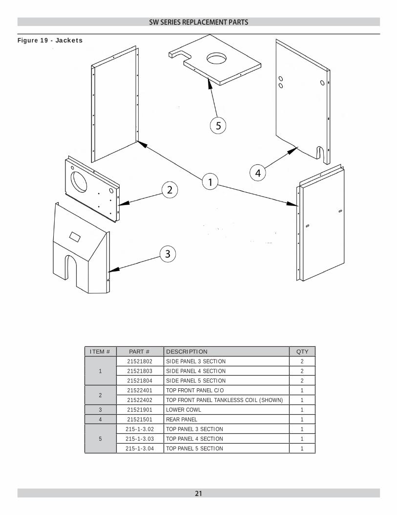
ITEM # PART # DESCRIPTION QTY
1
21521802 SIDE PANEL 3 SECTION 2
21521803 SIDE PANEL 4 SECTION 2
21521804 SIDE PANEL 5 SECTION 2
221522401 TOP FRONT PANEL C/O 1
21522402 TOP FRONT PANEL TANKLESSS COIL (SHOWN) 1
3 21521901 LOWER COWL 1
4 21521501 REAR PANEL 1
5
215-1-3.02 TOP PANEL 3 SECTION 1
215-1-3.03 TOP PANEL 4 SECTION 1
215-1-3.04 TOP PANEL 5 SECTION 1
Figure 19 - Jackets
22
SW SERIES REpLACEmENt pARtS
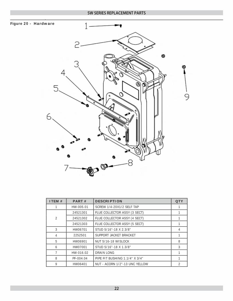
ITEM # PART # DESCRIPTION QTY
1 HW-005.01 SCREW 1/4-20X1/2 SELF TAP 1
2
24521301 FLUE COLLECTOR ASSY (3 SECT) 1
24521302 FLUE COLLECTOR ASSY (4 SECT) 1
24521303 FLUE COLLECTOR ASSY (5 SECT) 1
3 HW06701 STUD 5/16"-18 X 2.3/8" 4
4 2252501 SUPPORT JACKET BRACKET 1
5 HW06901 NUT 5/16-18 WISLOCK 8
6 HW07001 STUD 5/16"-18 X 1.3/8" 3
7 HW-016.02 DRAIN LONG 1
8 PF-004.04 PIPE FIT BUSHING 1.1/4" X 3/4" 1
9 HW06401 NUT - ACORN 1/2"-13 UNC YELLOW 2
Figure 20 - Hardware

23
SW SERIES REpLACEmENt pARtS
ITEM # PART # DESCRIPTION QTY
1 1580004 TERMINATION 4" FLEX-L CFTSW4-UT 1
2 1580005 TERM. KIT 4" FLEX-L CFK104-UT INCLUDES A,B,C
A) TERMINAL ADAPTER CFAT44 1
B) 10' x 4' VENT KIT CFV104/6 1
C) APPLIANCE ADAPTER CFAA44P 1
Figure 21 - Termination Kit Assembly

24
SW SERIES REpLACEmENt pARtS
BURNER COMPONENTS
ITEM # PART # DESCRIPTION QTY
1
BN08701 BURNER OIL UT1601 AFII 100 (SW3) 1
BN08702 BURNER OIL UT1602 AFII 100 (SW4) 1
1050012 BURNER OIL UT1603 AFII 150 (SW5) 1
2BN08001 BURNER OIL FLANGE GASKET #3616 1
30A055901 GASKET OB MT FLG #3416 1
3 CD-001.01 CAD CELL (FOR BOILERS WITH BECKETT ONLY) 1
4RY00501 CONTROL R1784P1031 (HONEYWELL) 1
240008817 CONTROL 7505P152M (BECKETT) 1
5
NZ01001 NOZZLE .60 45B (SW3) (BECKETT) 1
NZ01101 NOZZLE .85 45B (SW4) (BECKETT) 1
1320021 NOZZLE 1.10 45B (SW5) (BECKETT) 1
1320022 NOZZLE .60 80W (SW3) (RIELLO) 1
1320023 NOZZLE .80 60W (SW4) (RIELLO) 1
1320024 NOZZLE 1.10 60B (SW5) (RIELLO) 1
6
CALL BURNER OIL 40BF3 - (SW3) (RIELLO) 1
CALL BURNER OIL 40BF5 - (SW4) (RIELLO) 1
CALL BURNER OIL 40BF5 - (SW5) (RIELLO) 1
BECKETT AFII BURNER PARTS
1 RP03801 BLAST TUBE AF2
2 RP03901 FUEL PUMP AF2 DANFOSS
3 RP04001 7" DRAWER ASSY AF2
4 RP04101 OIL BRN TRANSFORMER AF2
5 RP04201 OIL BRN MOTOR AF2
6 RP03701 FUEL PUMP
7 RP04401 SOLENOID VALVE COMB.
RIELLO BURNER PARTS
1 30A064701 BRN PUMP DRIVE KEY RIELLO
2 30A064801 BRN PRIMARY CTRL-53OSE RIELLO
3 30A064901 BRN COIL RIELLO
4 30A065101 BRN MOTOR RIELLO
5 30A065201 BRN CAPACITOR 12.5uF RIELLO
6 30A065301 BRN ELECTRODE PORCELAIN RIELLO
7 30A065401 BRN PUMP RIELLO
8 30A065501 BRN HYDRAULIC JACK RIELLO
9 30A065601 BRN O-RING PUMP PRESS RIELLO
10 30A065701 BRN PHOTO CELL RIELLO
11 10500015 BRN K7R POST PURGE CONTROL
25
SW SERIES REpLACEmENt pARtS
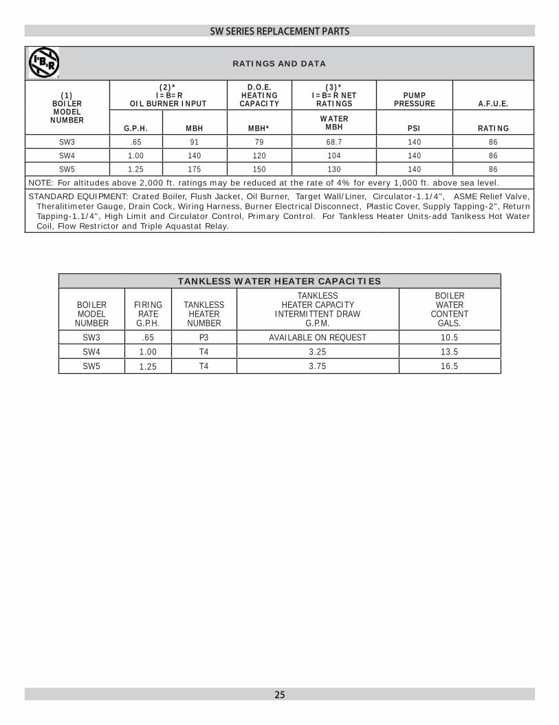
RATINGS AND DATA
(1) BOILER MODEL
NUMBER
(2)* I=B=R
OIL BURNER INPUT
D.O.E. HEATINGCAPACITY
(3)* I=B=R NET RATINGS
PUMP PRESSURE A.F.U.E.
G.P.H. MBH MBH*WATER
MBH PSI RATING
SW3 .65 91 79 68.7 140 86
SW4 1.00 140 120 104 140 86
SW5 1.25 175 150 130 140 86
NOTE: For altitudes above 2,000 ft. ratings may be reduced at the rate of 4% for every 1,000 ft. above sea level.
STANDARD EQUIPMENT: Crated Boiler, Flush Jacket, Oil Burner, Target Wall/Liner, Circulator-1.1/4", ASME Relief Valve, Theralitimeter Gauge, Drain Cock, Wiring Harness, Burner Electrical Disconnect, Plastic Cover, Supply Tapping-2", Return Tapping-1.1/4", High Limit and Circulator Control, Primary Control. For Tankless Heater Units-add Tanlkess Hot Water Coil, Flow Restrictor and Triple Aquastat Relay.
TANKLESS WATER HEATER CAPACITIES
BOILER MODEL
NUMBER
FIRING RATE G.P.H.
TANKLESS HEATER NUMBER
TANKLESS HEATER CAPACITY
INTERMITTENT DRAW G.P.M.
BOILER WATER
CONTENT GALS.
SW3 .65 P3 AVAILABLE ON REQUEST 10.5
SW4 1.00 T4 3.25 13.5
SW5 1.25 T4 3.75 16.5

26
dImENSIONS
BOILER NO.
A LENGTH OF FLUSH
JACKET
B FRONT OF CASTING TO CENTER LINE OF
FLUE OUTLET
C
DIAMETER OF FLUE OUTLET
SW3 17.7/8" 11.1/4" 4"
SW4 21.1/2" 12.5/8" 4"
SW5 25.1/8" 14.1/4" 4"
NOTES:1. Add suffix "T" to denote boiler with tankless heater.2. I=B=R burner capacity is based on an oil heating value of 140,000 Btu/gal. and with 13% CO2.3. Net ratings based on 170 0 F temperature in radiators and include 15% allowance for normal piping and pickup
load. Consult manufacturers for unusual piping and pick-up requirements. * All ratings subject to verification.4. 120 Volts, 15 Amps, & 60 Hz. required to operate this boiler.5. The MEA number for the SFH-W series is 182-86E6. The MEA number for the Beckett burners used on the SFH-W are as follows: AFII 100 456-90-E AFII 150 456-90-E

27
SW SERIES OIL FIREd dIRECt ExhAuSt CASt IRON BOILER

SWOIL FIRED DIRECT EXHAUST
CAST IRON BOILER