installation overthe range instructions microwave oven i · pdf filecarl 1-800-944-9044(us)...
TRANSCRIPT
InstallationInstructions
Overthe RangeMicrowave Oven
IQuestions? Carl 1-800-944-9044(us)1-800-265-8352(Canada) or Visit our Website at: http://www.frigidaire.com I
BEFORE YOU BEGINRead these instructions completely and carefully.
• IMPORTANT - Savetheseinstructions for local inspector's use.
• IMPORTANT - Observoallgoverning codes and ordinances.
• Note to Installer - Be sure to leave these
instructions with the Consumer.
• Note to Consumer - Keep theseinstructions for future reference.
• Skill level - Installation of this appliance requiresbasic mechanical and electrical skills.
• Proper installation is the responsibility of the installer.
• Product failure due to improper installation is notcovered under the Warranty.
//
READ CAREFU LLY.
KEEP THESE INSTRUCTIONS.
pin 316495064

Installation Instructions
CONTENTS
General information
Important Safety Instructions .................................. 3
Electrical Requirements .......................................... 3
Damage - Shipment/Installation .............................. 4
Parts Included .......................................................... 4
Tools You Will Need ................................................ 5
Mounting Space ...................................................... 5
Step-by-step installation guide
Placement of The Mounting Plate ...................... 6-8
Removing the Mounting Plate ...................... 6
Finding the Wall Studs .................................. 6
Determining Wall Plate Location .................. 7
Aligning the Wall Plate ................................ 8
Installation Types ................................................ 9-22
Hood Exhaust .................................................. 10-11
_ Outside Top ............................Exhaust 12-15
Attach Mounting Plate to Wall ............ 12
Preparation of Top Cabinet ................ 13
Adapting Microwave Blower for
Outside top Exhaust .................. 13-14
Checking for Proper DamperOperation ............................................ 14
Mount the Microwave Oven .......... 14-15
Adjust the Exhaust Adaptor ................ 15
Connecting Ductwork .......................... 15
1_ Outside Back Exhaust 16-19
Preparing Rear Wall forOutside Back Exhaust .......................... 16
Remove Blower Plate .............................. 16
Attach Mounting Plate to Wall ............ 17
Preparation of Top Cabinet ................ 17
[]
Adapting Microwave Blowerfor Outside Back Exhaust ................ 17-18
Mount the Microwave Oven ................ 19
Recirculating ........................................ 20 -22
Attach Mounting Plate to Wall ............ 20
Preparation of Top Cabinet ................ 20
Check Blower Plate ............................ 21
Mount the Microwave Oven .......... 21-22
Before You Use Your Microwave .......................... 23
2

Installation Instructions
IMPORTANT SAFETY INSTRUCTIONS
This product requires a three-prong grounded outlet.
The installer" must perform a ground continuity check
on the power" outlet box before beginning the
installation to insure that the outlet box is properly
grounded. If not properly grounded, or" if the outlet
box does not meet electrical requirements noted
(under ELECTRICAL REQUIREMENTS), a qualified
electrician should be employed to correct anydeficiencies.
CAUTION: For personal
safety, remove house fuse
or open circuit breaker
before beginninginstallation to avoid severe
or fatal shock injury.
CAUTION: For personal safety, the mounting surfacemust be capable of supporting the cabinet load, inaddition to the added weight of this 63-85 pound(28.5-38.5 kg) product, plus additional oven loads of
up to 50 pounds (22.7 kg) or a total weight of113-135 pounds (51.3-61.2 kg).
CAUTION: For personal safety, this product cannotbe installed in cabinet arrangements such as an island ora peninsula. It must be mounted to BOTH a top cabinetAND a wall.
NOTE: For easier installation and personal safety, it is
recommended that two people install this product.
IMPORTANT - PLEASE READ CAREFULLY. FORPERSONAL SAFETY, THIS APPLIANCE MUST BEPROPERLY GROUNDED TO AVOID SEVERE ORFATAL SHOCK.
Ensurepropergroundexistsbeforeuse
The power cord of thisappliance is equipped with athree-prong (grounding)
plug which mates with astandard three-prong(grounding) wall receptacleto minimize the possibilityof electric shock hazard
from this appliance.
You should have the wall receptacle and circuit checkedby a qualified electrician to make sure the receptacle isproperly grounded.
Where a standard two-prong wall receptacle is
encountered, it is very important to have it replaced
with a properly grounded three-prong wall receptacle,
installed by a qualified electrician.
DO NOT, UNDER ANY CIRCUMSTANCES, CUT,DEFORM OR REMOVE ANY OF THE PRONGSFROM THE POWER CORD. DO NOT USE WITHAN EXTENSION CORD.
ELECTRICALREQUIREMENTSProduct rating is 120 volts AC, 60 Hertz, 15 amps and
1.6 kilowatts. This product must be connected to a
supply circuit of the proper voltage and frequency.
Wire size must conform to the requirements of the
National Electrical Code or the prevailing local
code for this kilowatt rating. The power supply
cord and plug should be brought to a separate
15- to 20- ampere branch circuit single grounded
outlet. The outlet box should be located in the
cabinet above the microwave oven. The outlet box
and supply circtfit should be installed by a qualified
electrician and conform to the National Electrical
Code or the prevailing local code.
3

Installation Instructions
DAMAGE--SHIPMENT/INSTALLATION
• If the unit is damaged in shipment, return the
unit to the store in which it was bought for repairor replacement.
• If the unit is damaged by the customer, repair orreplacement is the responsibility of the customer.
• If the unit is damaged by the installer (if other
than the customer), repair or replacement mustbe made by arrangement between customerand installer
PARTS INCLUDED
HARDWARE PACKETPART
/
+!
j_
Wood Screws
(1/4" X 2")
ToggleBolts(andwing nuts) (3/16"x 3")
Self-AligningMachineScrews(1/4"-28x 31/4'')
NylonGrommet(for metalcabinets)
PowerCordStrap(plastic)
QUANTITY
2
You will find the installation hardware contained in
a packet with the unit. Check to make sure you have
all these parts.
NOTE: Some extra parts are included.
PARTS INCLUDED (CONT.)
ADDITIONAL PARTS
PART
TOP CABINETTEMPLATE
REARWALL
TEMPLATE
TopCabinetTemplate
RearWallTemplate
InstallationInstructions
SeparatelyPackedGreaseFilters
Exhaustadaptor
GlassTray
TurntableRing
QUANTITY
1
4
Installation Instructions
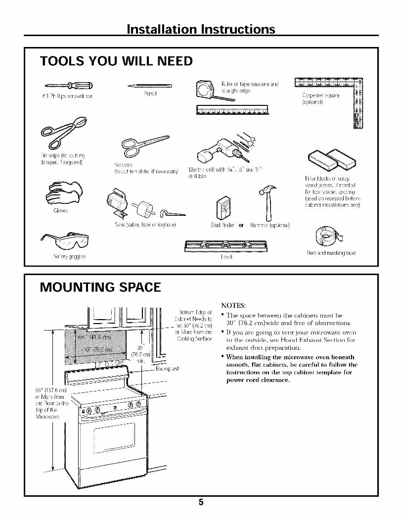
TOOLS YOU WILL NEED
# 1 Phillipsscrewdriver
Tin snips (for cuttingdamper, if required)
Gloves
Safetygoggles
PencilRuler or tape measure and
t edge
Scissors
(to cut template, if necessary)
Saw (saber, hole or keyhole)
Electric drill with 3/16",1/2"and %"drill bits
0Stud finder or Hammer (optional)
Level
Carpentersquare(optional)
Fillerblocksor scrapwoodpieces,if neededfor top cabinetspacing(usedon recessedbottomcabinet installationsonly)
Duct and masking tape
MOUNTING SPACE
66" (167,6cm)or Morefromthe Floorto the
Topof theMicrowave
_lash
BottomEdgeofCabinetNeedstobe30" (76,2cm)
or Morefrom theCookingSurface
NOTES:
• The space between the cabinets must be
30" (76.2 cm)wide and free of obstructions.
• If you are going to vent your microwave oven
to the outside, see Hood Exhaust Section for
exhaust duct preparation.
• When installing the microwave oven beneath
smooth, flat cabinets, be careful to follow the
instructions on the top cabinet template for
power cord clearance.
5

Installation Instructions
PLACEMENT OF THE MOUNTING PLATE
I-_ REMOVING THE MICROWAVEOVEN FROM THE CARTON/REMOVING THE MOUNTINGPLATE
[]Remove the installation instructions, filters, glass
tray and the small hardware bag. Do not remove
the Styrofoam protecting the front of the oven.
[] Fold back all 4 carton flaps fully against carton
sides. Then carefully roll the oven and carton over
onto the top side The oven should be resting in
the Styrofoam.
Styrofoam_
[]Pull the carton up and off the oven
[]Cut the middle of plastic bag toremove the mounting plate
MountingScrews-_ Plate
f
[]Remove the screws from the mounting plate.
This plate will be used as the rear wall template
and for mounting. Reinstall the screws into the
holes where they were removed.
I-_ FINDING THE WALL STUDS
[]Find the studs, using one of the followingmethods:
A. Stud finder - a magnetic device whichlocates nails.
OR
B. Use a hammer to tap lightly across the
mounting surface to find a solid sound.This will indicate a stud location
[] After locating the stud(s), find the center by
probing the wall with a small nail to find the edges
of the stud. Then place a mark halfway between
the edges. The center of any adjacent studs should
be 16" (40.6 cm) or 24" (61 cm) from this mark.
[]Draw a line down the center of the studs.
THE MICROWAVE MUST BE CONNECTED TOAT LEAST ONE WALL STUD.
6

Installation Instructions
DETERMINING WALL PLATE LOCATION UNDER YOUR CABINET
Plate positionmbeneath flat bottomcabinet
Plate positionmbeneath framed recessedcabinet bottom
MountingPlateTabsTouchingthe CabinetBottom
At least30" (76.2cm),up to 36" (9!.4 cm)
MountingPlateTabs.Touchingthe BackFrame
iII i i 30" (76,2 cm)
to Cooktop
Plate position_beneath recessed bottomcabinet with front overhang
Mounting Plate withTabs Below CabinetBottom the Same
Distance as the Front
Overhang Depth
30" (76,2 cm)to Cooktop
!
Your cabinets may have decorative trim thatinterferes with the microwave installation. Remove
the decorative trim to install the microwave properlyand to make it level.
THE MICROWAVE MUST BE LEVEL.Use a level to make sure the cabinet bottom is level.
If the cabinets have a front overhang only, with noback or side frame, install the mounting plate downthe same distance as the front overhang depth. Thiswill
[]%
%
keep the microwave level.
Measure the inside depth of the front overhang.
Draw a horizontal line on the back wall an equaldistance below the cabinet bottom as the inside
depth of the front overhang.
For this type of installation with front overhang only,
align the mounting tabs with this horizontal line, not
touching the cabinet bottom as described in Step D.
7

Installation Instructions
ALIGNING THE WALL PLATE
CAUTION: Wear gloves
to avoid cutting fingers on
sharp edges.
. s
[_-_ Draw a Vertical °:t[ Line on Wall _Il from Center of ,:1
Centerline [ Top Cabinet i!tNotches [ J:l
I
-_? o o ? o o cF--o---_o c _ o o Or---o-_o o o_
I ,Hole C Area E
I
I
i\ Hole D
[]Draw a vertical line on the wall at the center of the
30" (76.2 cm) wide space.
[]Use the mounting plate as the template for the rear
wall. Place the mounting plate on the wall, making
sure that the tabs are touching the bottom of the
cabinet or the level line drawn in Step C for cabinets
with front overhang. Line up the notch and centerline
on the bottom of the mounting plate to the centerlineon the wall.
[]While holding the mounting plate with one hand,
draw circles on the wall at holes A, B, C and D(see illustration above/actual plate marked with
arrows). Four holes must be used for mounting.
[]
NOTE: If neither C nor D is in a stud, find a stud
somewhere in area E and draw a fifth circle to line up
with the stud. It is important to use at least one wood
screw mounted firmly in a stud to support the weight
of the microwave.
Set the mounting plate aside.
Drill holes on the circles. If there is a stud, drill a 3/16'1
hole for wood screws. For holes that don't line up with
a stud, drill a 5/8" hole for toggle bolts.
NOTE: DO NOT MOUNT THE PLATE ATTHIS TIME.
8

Installation Instructions
INSTALLATION TYPES
This microwave oven is designed for adaptation to
the following three types of ventilation:
A. Outside Top Exhaust (Vertical Duct)
B. Outside Back Exhaust (Horizontal Duct)
C. Recirculating (Non-Vented Ductless)
(Choose A, B or C)
NOTE: This microwave is shipped assembled for
Recirculating. Select the type of ventilation required
for your installation and proceed to that section.
-_ OUTSIDE TOP EXHAUST(VERTICAL DUCT)
OUTSIDE BACK EXHAUST(HORIZONTAL DUCT)
Adaptorin PlaceforOutsideTopExhaust
AdaptorMust BeMovedto the BackforOutsideBackExhaust
[_ RECIRCULATING(NON-VENTED DUCTLESS)
9

Installation Instructions
HOOD EXHAUSTNOTE: Read these next two pages only if you plan to vent your exhaust to theoutside. If you plan to recircnlate the air back into the room, proceed to page 6.
OUTSIDE TOP EXHAUST (EXAMPLE ONLY)The following chart describes an example of one possible
ductwork installation.
DUCT PIECES
[]
Roof Cap
12Ft,(3,6m)StraightDuct(6'715,2cmRound)
EQUIVALENT NUMBER EQUIVALENTLENGTH x USED = LENGTH
Rectangular-to-RoundTransitionAdaptor*
24 Ft,(7,3m) x (1)
12Ft,(3,6m) x (1)
[]
5 Ft, (1,5m) x
Equivalentlengthsof ductpiecesare basedon actualtests andreflect requirementsfor goodventingperformancewith anyventhood,
(1)
24 Ft,(7,3m)
12Ft,(3,6m)
5 Ft, (1,5m)
Total Length = 41 Ft. (12.5 m)
* IMPORTANT: If a rectangular-to-round transition adaptor is used, the bottom corners of the damper
will have to be cut to fit, using the tin snips, ira order to allow fi'ee movement of the damper'.
OUTSIDE BACK EXHAUST (EXAMPLE ONLY)The following chart describes an example of one possibleductwork installation.
EQUIVALENTDUCT PIECES LENGTH* x
_[_ Cap (12,2m) xWall 40Ft,
3 Ft,StraightDuct 3 Ft,(0,9m) x(31/g'x 10'78,2x 25,4cm
_- Rectangular)
90° Elbow 10Ft, (3m) x
NUMBER
USED
(1)
(1) =
(2) =
EQUIVALENTLENGTH
40Ft, (12,2m)
3 Ft,(0,9m)
20Ft, (3m)
Equivalentlengthsof ductpiecesarebasedonactual testsandreflect requirementsfor goodventingperformancewith anyvent hood,
Total Length = 63 Ft. (19.2 m)
NOTE: For back exhaust, care should be taken to align exhaust with space between studs, or wall should be preparedat the time it is constructed by leaving enough space between the wall studs to accommodate exhaust.
10

Installation Instructions
NOTE: If you need to install ducts, note that the total
duct length of 31/4'' x 10" (8.2 x 25.4 cm) rectangular or
6" (15.2 cm) diameter round duct should not exceed
120 equivalent feet (36.5 m).
Outside ventilation requires a HOOD EXHAUST DUCT.Read the following carefully.
NOTE: It is important that venting be installed using
the most direct route and with as few elbows as possible.
This ensures clear venting of exhaust and helps prevent
blockages. Also, make sure dampers swing freely and
nothing is blocking the ducts.
Exhaust connection:
The hood exhaust has been designed to mate witha standard 31/4'' x 10" (8.2 x 25.4 cm) rectangular duct.
If a round duct is required, a rectangulat_to-roundtransition adaptor must be used. Do not use less thana 6" (15.2 cm) diameter duct.
Maximum duct length:For satisfactory air movement, the total duct length of31/4" x 10" (8.2 x 25.4 cm) rectangular or 6" (15.2 cm)
diameter round duct should not exceed 120 equivalentfeet (36.5 m).
Elbows, transitions, wall and roof caps,etc., present additional resistance to airflow and are
equivalent to a section of straight duct which is longerthan their actual physical size. When calculating the total
duct length, add the equivalent lengths of all transitionsand adaptors plus the length of all straight duct sections.
The chart below shows you how to calculate totalequivalent ductwork length using the approximate feet
of equivalent length of some typical ducts.
DUCT PIECES
&i
%
0
Rectangular-to-RoundTransitionAdaptor*
Wall Cap
90° Elbow
45° Elbow
90° Elbow
45° Elbow
RoofCap
StraightDuct6" (15,2cm)Roundor 31/4̀̀x 10"(8,2x 25,4cm)Rectangular
EQUIVALENTLENGTH
5 Ft, (1,5m)
40 Ft,(12,2m)
10 Ft,(3 m)
5 Ft, (1,5m)
25Ft, (7,6m)
5 Ft, (1,5m)
24 Ft,(7,3m)
1 Ft, (0,3m)
NUMBER
x USED
x ()
x ()
x ()
x ()
x ()
x ()
x ()
x ()
EQUIVALENTLENGTH
Ft,or m
Ft,or m
Ft,or m
Ft,or m
Ft,or m
Ft,or m
Ft,or m
Ft,or m
mi
Total Ductwork = Ft. or m
* IMPORTANT: If a rectangular to round transitionadaptor is used, the bottom corners of the damper
will have to be cut to lit, using the tin snips, in orderto allow free movement of the damper.
Equivalent lengths of duct pieces are based on actual testsand reflect requirements for good venting performance withany vent hood.
11

Installation Instructions
OUTSIDE TOP EXHAUST (Vertical Duct)
INSTALLATION OVERVIEW
A|. Attach Mounting Plate to WallA2. Prepare Top Cabinet
A3. Adapting Microwave Blower for
Outside Top ExhaustA4. Check Damper OperationA5. Mount Microwave Oven
A6. Adjust Exhaust AdaptorA7. Connect Ductwork
IMPORTANT NOTES:
• Make sure the screws for the
blower motor and blower plate
are securely tightened when
they are reinstalled. This will
help to prevent excessive
vibration.
• Make sure the motor wiring has
been properly routed and secured,
and that the wires are not pinched.
ATTACH THE MOUNTINGPLATE TO THE WALL
Attach the plate to the wall using toggle bolts.
At least one wood screw must be used to attach
the plate to a wall stud.
[]Remove the from the bolts.toggle wings
[]Insert the bolts into the mounting plate
through the holes designated to go into drywall
and reattach the toggle wings to 3/4" (19 mm) onto
each bolt.
To use toggle bolts:
MountingPlate,
Spacing for TogglesMore Than Wall
-_l_i_--ThicknessI
i Toggle Wings
Bolt End
]Place the mounting plate against the wall and
insert the toggle wings into the holes in the wall
to mount the plate.
NOTE: Before tightening toggle bolts and wood
screw, make sure the tabs on the mounting plate
touch the bottom of the cabinet when pushed
flush against the wall and that the plate is properly
centered under the cabinet.
CAUTION: Be careful to avoid pinching fingers
between the back of the mounting plate and the wall.
]Tighten all bolts. Pull the plate away fl'om the wall
to help tighten the bolts.
12

Installation Instructions
I-_ USE TOP CABINET TEMPLATEFOR PREPARATION OF TOPCABINET
You need to drill holes for the top support screws, a
hole large enough for the power cord to fit through,
and a cutout large enough for the exhaust adaptor.
• Read the instructions on the TOP CABINETTEMPLATE.
• Tape it underneath the top cabinet.
• Drill the holes, following the instructions on the
TOP CABINET TEMPLATE.
CAUTION: Wear safety goggles when drilling holesin the cabinet bottom.
ADAPTING MICROWAVEBLOWER FOR OUTSIDETOP EXHAUST
[] Place the microwave in its upright position,
with the top of the unit facing up.
?II
_ BI0wer Plate
<l__---------._,_--__f] 1 Back0r Micr0wave ,ow r o orScrew
Remove the screw that holds the blower plateto the microwave. Remove and save the screw
holding the blower motor to the microwave.
Careflflly pull out the blower unit. The wires
will extend far enough to allow you to adjust
the blower unit.
Microwave
Roll the blower unit 90 ° so that fan blade
openings are facing out the top of themicrowave.
Before Rotation After Rotation
Microwave Microwave
[]Place the blower unit back into the opening.
BackofMicrowave
CAUTION: Do not pull or stretch the blower
unit wiring. Make sure the wires are not
pinched, and that they are properly secured.
13

Installation Instructions
ADAPTING MICROWAVEBLOWER FOR OUTSIDETOP EXHAUST
[_] Secure blower unit to microwave with the screw
removed in Step 1. Make sure the screw is tight.
[_] Replace blower plate with the screw removed inStep 1. Make sure the screw is tight.
TI
Back of
Micr0wave
Attach the exhaust adaptor to the top of the
blower plate by sliding it into the guides of the
blower plate.
Adaptor
Guide "_-_
k0cking lab
Push in securely until it is in the locking tabs.
Take care to assure that the damper hinge is
installed so that the damper swings freely.
F_ CHECK FOR PROPERDAMPER OPERATION
Blower Plate Exhaust Adaptor
_' ,,._.__-,,_.----Damper
• Make sure tape securing damper is removed and
damper pivots easily before mounting microwave.
• You will need to make adjustments to assure proper
alignment with your house exhaust duct after themicrowave is installed.
I-_ MOUNT THE MICROWAVEOVEN
FOR EASIER INSTALLATION AND PERSONALSAFETY, WE RECOMMEND THAT TWO PEOPLEINSTALL THIS MICROWAVE OVEN.
IMPORTANT: Do not grip or use handleduring installation.
NOTE: If your cabinet is metal, use the nylon
grommet around the power cord hole to prevent
cutting of the cord.
NOTE: We recommend using filler blocks if the
cabinet front hangs below the cabinet bottom shelf.
IMPORTANT: If filler blocks are
not used, case damage may occur fromovertightening screws.
NOTE: When mounting the
microwave oven, thread
power cord through hole in
bottom of top cabinet. Keep
it tight throughout Steps
1-3. Do not pinch cord or
lift oven by pulling cord.
[]Rotate fl'ont of oven
up against cabinet
bottom.
%
[]Lift tilt itmicrowave,
forward, and hook
slots at back bottom
edge onto four lower
tabs of mounting
plate.
Insert a self-aligning screw through top center
cabinet hole. Temporarily secure the oven by
turning the screw at least two full turns after the
threads have engaged. (It will be completely
tightened later.) Be sure to keep power cord
tight. Be careful not to pinch the cord, especially
when mounting flush to bottom of cabinet.
14

Installation Instructions
MOUNT THE MICROWAVEOVEN (cont.)
Cabinet Front
..._._/_ Cabinet Bottom Shelf
/ Filler Block
/ _F_[TrT/_ TEq uivalent
/ /: :bPitnhet_:__!tI Ils' _L Recess
J"\l !U _-_ Self-Aligning ScrewMicrowave Oven Top
I_ Attach the microwave oven to the top cabinet.
[] Insert 2 self-aligning screws
through outer top cabinetholes. Turn two flfll turns on
each screw.
[]Tighten center
screw completely.
[] Tighten the outer two screws to the top of the
microwave oven. (While tightening screws, hold
the microwave oven in place against the wall and
the top cabinet.)
[] Install grease filters. See the Owner's Manual
packed with the microwave.
ADJUST THE EXHAUSTADAPTOR
Open the top cabinet and adjust the exhaust adaptorto connect to the house duct.
BackofBlowerPlate Damper Microwave
Side-to-SideAdjustment,Slide the ExhaustAdaptoras Needed
I-_ CONNECTING DUCTWORK
HouseDuct
]Extend the house duct down to connect to
the exhaust adaptor.
]Seal exhaust duct joints using furnance duct tape
for high temperature applications.
15

Installation Instructions
OUTSIDE BACK EXHAUST (Horizontal Duct)
INSTALLATION OVERVIEWBI. Prepare Rear WallB3. Remove Blower Plate
B3. Attach Mounting Plate to Wall
B4. Prepare Top CabinetBS. Adjust BlowerB6. Mount the Microwave Oven
IMPORTANT NOTES:
• Make sure the screws for the
blower motor and blower plate
are securely tightened when
they are reinstalled. This will
help to prevent excessive
vibration.
• Make sure the motor wiring has
been properly routed and secured,
and that the wires are not pinched.
PREPARING THE REAR WALLFOR OUTSIDE BACK EXHAUST
You need to cut an opening in the rear wall foroutside exhaust.
• Read the instructions on the REARWALL TEMPLATE.
• Tape it to the rear wall, lining up with the
holes previously drilled for holes A and Bin the wall plate.
• Cut the opening, following the instructions of theREAR WALL TEMPLATE.
REMOVE BLOWER PLATE
Remove and save the screw that holds the blower
plate to the microwave. Lift off the blower plate.
Blower Plate
I _ _ _ BackofMicrowave
16

Installation Instructions
_] ATTACH THE MOUNTINGPLATE TO THE WALL
Attach the plate to the wall using toggle bolts.
At least one wood screw must be used to attach
the plate to a wall stud.
]Remove the toggle wings from the bolts.
]Insert the bolts into the mounting plate through
the holes designated to go into drywall and reattach
the toggle wings to 3/4" (19 mm) onto each bolt.
To use toggle bolts:
MountingPlate
Spacing for Toggles More
_-_i_,---Than Wall Thickness
roggle Wings
Bolt End
]Place the mounting plate against the wall and
insert the toggle wings into the holes in the wall
to mount the plate.
NOTE: Before tightening toggle bolts and wood
screw, make sure the tabs on the mounting plate
touch the bottom of the cabinet when pushed flush
against the wall and that the plate is properlycentered under the cabinet.
CAUTION: Be careflfl to avoid pinching fingers
between the back of the mounting plate and the wall.
Tighten all bolts. Pull the plate away from the wall
to help tighten the bolts.
USE TOP CABINET TEMPLATEFOR PREPARATION OF TOPCABINET
You need to drill holes for the top support screws and
a hole large enough for the power cord to fit through.
• Read the instructions on the TOP CABINETTEMPLATE.
• Tape it underneath the top cabinet.
• Drill the holes, following the instructions on the
TOP CABINET TEMPLATE.
CAUTION: Wear safety goggles when drilling holesin the cabinet bottom.
ADAPTING MICROWAVEBLOWER FOR OUTSIDEBACK EXHAUST
[]Remove and that holds blower motorsave screw
to microwave.
Blower Motor
- _ Blower Motorv .,_ Screw
Careflflly pull out the blower unit. The wires
will extend far enough to allow you to adjustthe blower unit.
EndA
17

Installation Instructions
ADAPTING MICROWAVEBLOWER FOR OUTSIDE
BACK EXHAUST (cont.)
[] Roll the blower" unit 90 °
Before Rotation After Rotation
Microwave
BackofMicrowave
Rotate blower unit counterclockwise 180 ° .
Before Rotation
Back ofMicrowave
After Rotation
Back of
M icrowave
[]Gently remove the wires from the grooves.
Reroute the wires through grooves on other side
of the blower unit.
Before Rerouting After Rerouting
Wires Routed Through Right Side Wires Routed Through Left Side
_6_ Roll the blower unit 90 ° so that fan blade
openings are facing out the back of the
microwave.
Before Rolling
M icrowave
After Rolling
Back of
Microwave
[]Place the blower unit back into the opening.
EndA
End
CAUTION: Do not pull or stretch the blower
unit wiring. Make sure the wires are not
pinched, and that they are properly secured.
NOTE: The blower unit exhaust
openings should match exhaustopenings on rear of microwave oven.
[ ecure the blower unit to the microwave withthe original screw.
Blower Plate
I _ Back of
,!_ Microwave
Blower MotorScrew
[]Replace the blower in theplate same positionas before with the screw. Make sure the screw
is tight.
[]Attach the exhaust the of theadaptor to Fear
oven by sliding it into the guides at the topcenter of the back of the oven.
Adaptor
BackofMicrowave
o
Locking TabsGuide
Guide
Push in securely until it is in the lower locking
tabs. Take care to assure that the damper hinge
is installed so that it is at the top and that the
damper swings freely.
18

Installation Instructions
MOUNT THE MICROWAVEOVEN
FOR EASIER INSTALLATION AND PERSONALSAFETY, WE RECOMMEND THAT TWO PEOPLEINSTALL THIS MICROWAVE OVEN.
IMPORTANT: Do not grip or use handleduring installation.
NOTE: If your cabinet is metal, use the nylon
grommet around the power" cord hole to prevent
cutting of the cord.
NOTE: We recommend using filler blocks if the
cabinet front hangs below the cabinet bottom shelf.
IMPORTANT: If filler blocks are not
used, case damage may occur fromovertightening screws.
NOTE: When mounting the
microwave oven, thread
power cord through hole in
bottom of top cabinet. Keep
it tight throughout Steps
1-3. Do not pinch cord or"
lift oven by pulling cord.[]Lift tilt itmicrowave,
forward, and hook
slots at back bottom
edge onto four lower
tabs of mounting
plate.
[]Rotate fl'ont of oven
up against cabinet
bottom.
[]Insert a self-aligning screw through top center
cabinet hole. Temporarily secure the oven by
turning the screw at least two full turns after the
threads have engaged. (It will be completely
tightened later:) Be sure to keep power cord
tight. Be careful not to pinch the cord, especially
when mounting flush to bottom of cabinet.
Cabinet Front
Cabinet Bottom Shelf
FillerBlock
-_ Equivalentto Depthof CabinetRecess
Self-Aligning Screw
Microwave Oven Top
[]Attach the microwave oven to the top cabinet.
[] Insert 2 self-aligning screws
through outer top cabinetholes. Turn two flfll turns on
each screw.
[]Tighten center
screw completely.
[] Tighten the outer two screws to the top of the
microwave oven. (While tightening screws, hold
the microwave oven in place against the wall and
the top cabinet.)
[] Install grease filters. See the Owner's Manual
packed with the microwave.
19

Installation Instructions
RECIRCULATING (Non-Vented Ductless)
INSTALLATION OVERVIEW
C1. Attach Mounting Plate to Wall
C3. Prepare Top Cabinet
C3. Check Blower Plate
C4. Mount the Microwave Oven
C5. Install or change Charcoal Filter
IMPORTANT NOTES:
• Make sure the screws for the blower motor and blower
plate are securely tightened when they are reinstalled.
This will help to prevent excessive vibration.
• Make sure the motor wiring has been properly routed
and secured, and that the wires are not pinched.
ATTACH THE MOUNTINGPLATE TO THE WALL
Attach the plate to the wall using toggle bolts.
At least one wood screw must be used to attach
the plate to a wall stud.
[]Remove the from the bolts.toggle wings
Insert the bolts into the mounting plate through
the holes designated to go into drywall and
reattach the toggle wings to 3/4" (19 mm) onto
each bolt.
To use toggle bolts:
MountingPlate,
Spacing for TogglesMore Than Wall
÷l_-_.i_,----ThicknessIl Toggle Wings
Bolt End
]Place the mounting plate against the wall and
insert the toggle wings into the holes in the wall
to mount the plate.
NOTE: Before tightening toggle bolts and wood
screw, make sure the tabs on the mounting plate
touch the bottom of the cabinet when pushed flush
against the wall and that the plate is properly
centered under the cabinet.
CAUTION: Be careful to avoid pinching fingers
between the back of the mounting plate and the wall.
Tighten all bolts. Pull the plate away from the wallto help tighten the bolts.
I-_ USE TOP CABINET TEMPLATEFOR PREPARATION OF TOPCABINET
You need to drill holes for the top support screws and
a hole large enough for the power cord to fit through.
• Read the instructions on the TOP CABINETTEMPLATE.
• Tape it underneath the top cabinet.
• Drill the holes, following the instructions on theTOP CABINET TEMPLATE
CAUTION: Wear safety goggles when drilling holes
in the cabinet bottom.
2O

Installation Instructions
CHECK BLOWER PLATE
Blower Plate
• Place the microwave in its upright position, with the
top of the unit facing up.
• Check to see that the blower plate is correctlyinstalled on the unit.
MOUNT THE MICROWAVEOVEN
FOR EASIER INSTALLATION AND PERSONALSAFETY, WE RECOMMEND THAT TWO PEOPLEINSTALL THIS MICROWAVE OVEN.
IMPORTANT: Do not grip or use handleduring installation.
NOTE: If your cabinet is metal, use the nylon
grommet around the power cord hole to prevent
cutting of the cord.
NOTE: We recommend using filler blocks if the
cabinet front hangs below the cabinet bottom shelf.
IMPORTANT: If filler blocks are not used,
case damage may occur from overtighteningscrews.
NOTE: When mounting the
microwave oven, thread
power cord through hole in
bottom of top cabinet. Keep
it tight throughout Steps
1-3. Do not pinch cord or
lift oven by pulling cord.
[]Lift microwave, tiltit forward, and hookslots at back bottom
edge onto four lowertabs of mountingplate.
[]Rotate front of oven
up against cabinet
bottom.
[]Insert a self-aligning screw through top center
cabinet hole. Temporarily secure the oven by
turning the screw at least two full turns after the
threads have engaged. (It will be completely
tightened later.) Be sure to keep power cord
tight. Be careful not to pinch the cord, especially
when mounting flush to bottom of cabinet.
Cabinet Front
Cabinet Bottom Shelf
Filler Block
Equivalentto Depth
of CabinetRecess
Self-AligningScrew
MicrowaveOvenTop
[]Attach the microwave oven to the top cabinet.
21

Installation Instructions
MOUNT THE MICROWAVEOVEN (cont.)
[] Insert 2 self-aligning screws
through outer top cabinetholes. Turn two full turns on
each screw.
I
[]Tighten center
screw completely.
[] Tighten the outer two screws to the top of the
microwave oven. (While tightening screws, hold
the microwave oven in place against the wall and
the top cabinet.)
[] Install grease filters. See the Owner's Manual
packed with the microwave.
22

Installation Instructions
BEFORE YOU USE YOUR MICROWAVE
Make sure the microwave oven has been
installed according to instructions. r_ Read the USE & CARE Manual.
I
r_ emove all packing material fl'om themicrowave oven.
r_ Install turntable ring and glass tray in cavity
'_ Replace house flJse or turn breaker back on.
% Plug power cord into a dedicated 15- to 20-ampelectrical outlet.
Ensure proper /_;_
ground exists /before use
1
I
F_ EEP INSTALLATION INSTRUCTIONSFOR THE LOCAL INSPECTOR'SUSE.
r_ FILL OUT PRODUCT REGISTRATION CARD
23

24 Printed in China