installation & owner’s manual - ameriglide · this manual has been provided to assist you...
TRANSCRIPT

This manual has been provided to assist you with lift installation and operation. For further assistance please contact
your authorized AmeriGlide dealer orAmeriGlide’s Technical SupportDepartment.
Tel: 866-294-4460
Vertical Platform Lift
AmeriGlide
Models: AMGHERC750-4 AMGHERC750-6 AMGHERC750-8
AMGHERC750-10 AMGHERC750-12 AMGHERC750-14
Installation & Owner’s Manual
SERIAL NO
DEALER

Table of ContentsInstalling the lift Using the Manual 2 When You Receive the Lift 3 Specifications 3 Safety 3 Code Requirements 4 Site Requirements 4 Required Tools 4 Required Materials 4 Preparing to Install the Lift 5 Controller Harness Connections 5 Installing the platform 6 Installing the outer guard panel 7 Installing the fixed ramp 7 Installing the folding ramp 8 Anchoring the Lift 9 Setting the Limit Switches 10 Verifying Operation of the Lift 11 Manual Override 12 Call-Sends (optional) 12 Top Landing Gate (optional) 13 EMI and Flush Strike (optional) 14 Platform Gate (optional) 15 Fascia Panel (optional) 16 Owner’s Section 17 Safety 18 Controls 19 Operating the Lift 20 Warranty 22
Using the Manual This manual will provide step by step instructions on how to install and operate your lift. Read and understand the entire manual before beginning to install the lift.
If you have any questions, contact technical service at 1-866-294-4460
2

When You Receive the LiftCheck the lift for shipping damage. If you see any damage contact the freight carrier to file a damage
claim.
Verify the products match that described on the packing list attached to the exterior packaging.
Verify the contents of the package match that shown below to the right.
SpecificationsPayload Capacity 750 lbs
Vertical Travel 53” – 171”
Foot Print VARIES
Platform Size 36”42” x 60”
x 54” / 36” x 60” / 42” x 54” /
Input Voltage 115vac - 20a
Control Voltage 24vac or 24vdc
Platform Speed 10 ft/min
Motor 1/2hp-90vdc or 1/2hp-24vdc
SafetyRead all instructions in this manual before installing or operating the lift.
Do not exceed the maximum payload capacity of 750 lbs.
Do not ride on the lift until it is anchored in place.
This product is designed only for lifting people and wheel chairs. Do not use it for any other purpose.
Always wear eye protection while installing or servicing this product.
Always disconnect this product from the electrical source before servicing it.
Only use the fasteners supplied with this lift.
Do not wear loose clothing or jewelry when working on this product.
Do not disable any safety equipment or switches supplied with this lift.
Stay away from all drive train components while the lift is operating.
3

Code RequirementsYour lift has been designed to meet ASME A18.1 section 2 and CSA B44/ASME A17.5, with the addition of certain options. Code requirements for Vertical Platform lifts vary depending on location. It is the installers responsibility to contact their local code enforcement office and determine all of the regulations they are subject to. You must do this before installing the Vertical Platform Lift.
Site Requirements The lift will require a 115vac 20amp grounded circuit.
Outdoor Installations will require a GFI protected circuit.
Only install the lift on a 4” thick , level 3,500 psi reinforced concrete slab.
Foot Print varies depending on platform size and options.
Required tools 1/2" Hammer Drill
3/8" Masonry Drill Bit
Appliance Dolly
Hammer
Level
Measuring Tape
Socket Wrench Set
Required materials 4 Floor anchors
AmeriGlide recommends securing the lift using our Anchor Kit. If you purchase you own floor anchors they must use 3/8” bolts and have a minimum tensile strength of 6000 LBS.
4

Preparing to Install the Lift
Final Site Inspection Verify the surface the lift will mount to is smooth and level. This surface must be made from 3,500 psi reinforced concrete with a minimum thickness of 4”. Verify that there is enough space for the lifts foot print. Be sure to include space neccesary for platform.
Caution: Verify that the running clearance around the lift complies with any codes for your area.
The horizontal gap between the edge of the platform and the upper landing must no less than 3/8” and no greater than 3/4”.
The horizontal gap between the guard panel and any wall or barrier must be no less than 2” and no greater than 3”.
Verify that sufficient head room exists above the lift. The lift will require 6’ 8” of clearance above the platform floor when the lift is at the upper landing.
Warning: The area between the floor where the lift is mounted and the top landing must be covered by a smooth vertical fascia. This is to to eliminate any pinch points between the platform and landing.
Connecting to Electricity The lift will require a 115 VAC 20 amp grounded electrical circuit. Depending on local codes, this connection may need to be routed in electrical conduit and hard-wired.
Warning: Do not ride on the lift until it has been anchored in place.
Controller Harness Connections
5
High VoltageCircuit Breaker(AC unit only)
Low VoltageCircuit Breaker
PlatformTraveling Cable
Phone JackConnection
Safety PanJumper
Upper LandingInterlock
Lower LandingInterlock
Upper & LowerCall Sends
Upper & LowerLimit Switches
Bypass Switches(Strikes only)

Installing the Platform
Step 1 The mounting bolts, nuts and spacers that secure the platform to the lift carriage are packaged in the small parts box. Begin by locating these pieces and setting aside.
Step 2 Position the platform by aligning the support legs with the carriage flanges that protrude from the front cover.
Step 3 Align the four mounting holes and insert a ½” x 3” bolt into each hole. The upper holes have a spacer that must be placed in between the carriagne flange and platform leg. Install the locknut on each bolt and tighten sufficiently (approx. 50 lb-ft.).
Step 4 Plug in the harness for the platform safety pan and unplug the safety pan jumper on the controller (ref pg 5). Secure the harnesses under the clip on top of the carriage flange.
6

Installing the Outer Guard PanelsStep 1 Remove the hexbolts on the corners of the platform. Insert the guard panel posts into the pockets in the platform. The smooth side of the guard panels should face in towards the center of the platform.
If you have a 90 degree exit platform, install the end guard panel using the provided bracket and bolt to inner guard panel.
Step 2 Install the platform control box on the rear guard panel using screws and nuts through the panel.
Step 3 Plug in the harness for the platform control box. Secure the harnesses under the clip on top of the carriage flange.
Installing Fixed RampStep 1 • Position the ramp after the lift is in its final location. • Maintain a gap of 3/8” to 3/4” between the ramp and platform. • Drill a pilot hole into the concrete and fasten using supplied concrete lags through ramp flanges.
7

Installing Auto-folding Ramp (optional)Step 1 Install the ramp roller guide on the side of the lift tower using the screws already installed in the panels.
Step 2 Attach the two ramp pivot tabs to the lower landing sides of the platform. Reinsert the hex bolts, one of which will go through the guard panel post, and tighten.
Step 3 Attach the ramp to the pivot tabs using shoulder bolts and locking nuts. Tighten the nuts until they seat against the bolt shoulder.
Step 4 Attach the ramp roller arm by bolting it to the underside of the ramp.
The ramp roller should align and make contact with the ramp roller guide.
8

Anchoring the LiftAnchorsAmeriGlide recommends securing the lift using the concrete anchors provided. If you purchase you own floor anchors they must be 3/8” minimum of sufficient length. All four floor anchors must be installed correctly in accordance to their instructions.
Step 1 he lift in its final location.
Verify that it is level and perpendicular to its surroundings and all running clearances are the proper dimension. Shim if necessary.
Step 2 Use the lift’s base as a template. Drill 4 holes into the concrete making sure that the holes are deep enough to accept the anchors.
Tip: Concrete dust may have settled into the holes you just drilled. Use a shop vacuum to clean out these holes. This will ensure the floor anchors set correctly.
Step 3 Secure the lift in place by tightening the floor anchor bolts.
Step 4 (800 or taller models)Taller lifts must have the top of the lift tower anchored into a solid surface to ensure running clearances remain constant.There are two options for anchoring the top of the tower:
1) For lifts going up to a landing such as a deck or porch, the optional tower brace is the preferred method. Instructions for the brace are packaged with it.
2) For lifts that are placed with the back of the tower against a solid wall such as inside of a hoistway, drilling two holes through the top tower cross brace and anchoring is preferred.
9
Anchor two locations

Setting the Limit SwitchesYour lift is equipped with upper and lower limit switches. The vertical location of these switches may be adjusted to fit your application. Typically the upper limit switch will need to be adjusted so the platform will stop level with the upper landing. The lower limit will typically not need adjusting.
Step 1 Verify the emergency switch is in the ON position. Run the lift in the up direction until the platform floor is level with the upper landing. Disconnect the lift’s power (at the building’s circuit breaker for AC units, at the battery box for DC units) before going to the next step.
Warning: Moving components can cut and crush. Do not operate the lift if you are in close proximity to any drive components. Be aware that loose clothing or jewelry may catch on moving parts.
Step 2 Remove the screws at the top of the lift that attach the front cover.
Step 3 Remove the front cover by tilting it forward and lifting upwards. The bottom of the front cover sits on a pin on either side of the lift frame. Set the cover aside in a safe location where it will not get damaged.
Step 4 Loosen the bolts that attaches the upper limit switch assembly. Slide the assembly down the track until the lower switch in the assembly comes in contact with the lift’s car. You should hear the limit switch click as contact is made. Retighten the set screw fastening the limit switch assembly in place.
Step 5 Replace the front cover and secure it with the screws you removed in step 1.
Step 6 Re-connect the lifts electricial power at the circuit breaker. Verify that the emergency switch is in the on position.
Step 7 Run the lift in the down direction for several inches. Next, run the lift in the up direction. Continue to press the up button until the upper limit switch has caused the lift to stop. Verify that the platform has stopped level with the upper landing. If it has not, readjust the limit until it is level.
10
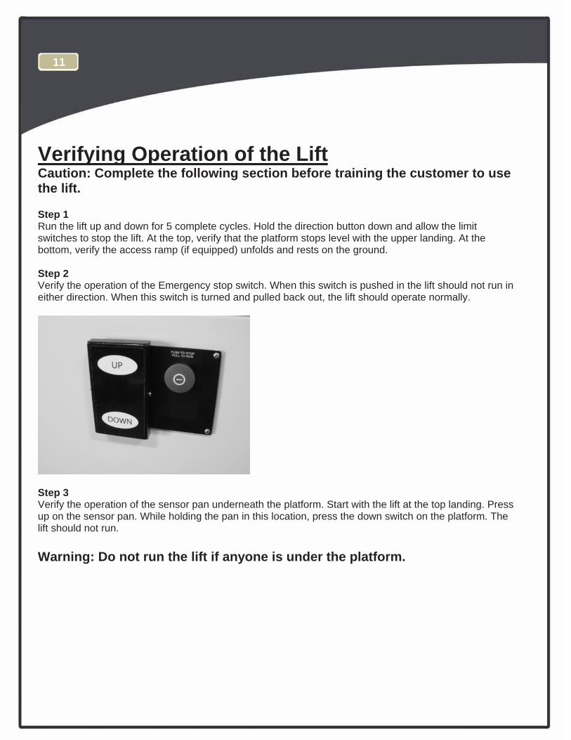
Verifying Operation of the LiftCaution: Complete the following section before training the customer to use the lift.
Step 1 Run the lift up and down for 5 complete cycles. Hold the direction button down and allow the limit switches to stop the lift. At the top, verify that the platform stops level with the upper landing. At the bottom, verify the access ramp (if equipped) unfolds and rests on the ground.
Step 2 Verify the operation of the Emergency stop switch. When this switch is pushed in the lift should not run in either direction. When this switch is turned and pulled back out, the lift should operate normally.
Step 3 Verify the operation of the sensor pan underneath the platform. Start with the lift at the top landing. Press up on the sensor pan. While holding the pan in this location, press the down switch on the platform. The lift should not run.
Warning: Do not run the lift if anyone is under the platform.
11

Manual OverrideYour lift is equipped with a manual handcrank, to be used in the case of a power failure.
Step 1 Before using the manual handcrank verify that it’s use is required. Check that the emergency stop switch is pulled out. Check that the electrical cord is connected to the supply. Also check that the buildings circuit breaker has not tripped. Try to run the lift by pushing both the up and down buttons. If the lift still will not run, complete the following steps:
Step 2 Disconnect the power from the lift. Warning: Do not service or operate the manual handcrank while the lift is connected to electricity.
Step 3 Remove the screws and remove the top cap at the top of the tower.
Step 4 Insert the manual handcrank into the opening on the top of the brake assembly. It may be neccesary to slightly rotate the handcrank until it fully seats down on the hex portion of the brake. Rotate the crank to raise or lower the platform.
Warning: Never operate the lift while the manual override crank is inserted into the lift.
Call-Sends (optional)The optional Call-Send controls are to be used at the upper and/or lower landings to call the platform to you or send it to the other landing.
They should be mounted on the wall at each landing at a convenient height. Consult local codes for placement with consideration to clearances.
12
A length of multi conductor wire willneed to be ran from the bottom of the lifttower up to the landing Call Sends.Consult local codes for type andmounting requirements. After wiring iscompleted, the wiring harness must beplugged into it appropriate receptacle onthe controller (ref pg 5).
Wiring Connections
Call Send Lift HarnessBlue BlueWhite WhiteRed Red

Top Landing Gate (optional)The optional top landing gate is provided with a combination mechanical lock and electric contact (interlock).
The interlock: Prevents the lift from running if the gate is not closed. Prevents the gate from being opened if the platform is
not at the top landing. Unlocks when the lift is on the upper limit switch.
A crescent shaped key is provided to manually unlock the gate during installation. The key is inserted from the back side to lift up on the solenoid that holds the gated locked.
Mount the gate by placing onto the upper landing making sure to align the gate opening with the platform (outer guard rail not shown for clearity). There are a number of attachment holes provided in the threshold portion of the gate for mounting using wood lag screws or concrete anchors as appropriate.
Remove the latch post cover and connect the call-send and interlock wire harnesses.
The vertical posts of the gate must be attached to a supporting structure, (the gate is not designed to be freestanding).
13
A length of multi conductor wire willneed to be ran from the bottom of the lifttower up to the landing gate. Consultlocal codes for type and mountingrequirements. After wiring is completed,the wiring harness must be plugged intoit appropriate receptacle on thecontroller (ref pg 5).
Wiring ConnectionsInterlock Harness Lift Harness
Black BlackBlack GreenYellow WhiteYellow Orange
*Blue* Brown
*Must be tied together
Call Send Harness Lift HarnessBlue BlueYellow WhiteRed Red

EMI and Flush Strike Interlocks (optional)The optional EMI or Flush Strike Interlocks are provided with a combination mechanical lock and electric contact. They are to be used with existing doors. The interlock:
Prevents the lift from running if the door is not closed.
Prevents the door from being opened if the platform is not at the landing.
A length of multi-conductor wire will need to be ran from the bottom of the lift tower to each interlock. Consult local codes for type and mounting requirements. After wiring is completed, the wiring harness must be plugged into it appropriate receptacle on the controller (ref pg 5).
Flush Strike Interlock Refer to the instructions inside the strike box for mounting requirements.
EMI Interlock
1) Position interlock to door jamb and mark mounting holes.
2) Fasten Interlock to door jamb with #8 wood screws.
3) Route 4-conductor Interlock cable thru hole in top of interlock and make wire connections.
4) Attach door keeper and emergency key plates to hoistway door.
14
EMI Interlock Wiring ConnectionsEMI Lift HarnessBlack (A) BlackBlack (B) GreenYellow (C) WhiteYellow (D) OrangeN/A Blue+N/A Brown+N/A Red
+Must be tied together when using an EMI Interlock.
Flush Strike Interlock Wiring ConnectionsFor AC powered lifts
Flush Strike Wires Rectifier Wires Lift Harness WiresBlack White Stripe RedBlack White Stripe Black
Yellow BlackYellow Green*
Yellow WhiteBlue OrangeGrey Blue
Green BrownRed Red
Black BlackYellow RedYellow Green*
For Optional DC powered liftsFlush Strike Wires Lift Harness WiresBlack White Stripe BlackBlack White Stripe Green*
Yellow WhiteBlue OrangeGrey Blue
Green BrownRed Red
Black Green**This is a single wire that will have 2 wires connected to it.

Platform Gate (optional)The optional platform gate is provided with a combination mechanical lock and electric contact (interlock).
The interlock: Prevents the lift from running if the gate is not closed. Prevents the gate from being opened if the platform is not at the bottom landing. Unlocks when the lift is on the lower limit switch.
A crescent shaped key is provided to manually unlock the gate during installation. The key is inserted from the back side to lift up on the solenoid that holds the gated locked.
Mount the gate by placing onto the lower landing side of the platform. There are a number of attachment holes along the bottom and up the sides of the gate frame to attach to the platform and guard panels.
A wiring harness included on the gate will need to be routed along the gate frame, behind the rear guard panel and connected to it’s adjoining harness plug on the lift carriage. After wiring connection is made, the wiring harness must be plugged into it’s appropriate receptacle on the contoller (ref pg 5).
15

Fascia Panel (optional)A fascia panel provides a smooth surface for the platform edge to run against to prevent any shear or obstruction hazards and must be utilized.
A running clearance of no more than 3/4” and no less than 3/8” must be maintained between the edge of the platform and the fascia panel.
16

Commercial Platform Lift - Owners Section
Read the manual thoroughly before operating the lift.
17

Congratulations on the purchase of your AmeriGlide Vertical Platform Lift. This lift has been engineered to provide trouble free service for many, many years. Please read this manual completely before operating your lift.
Safety Do not exceed the maximum payload capacity of 750 lbs.
Do not ride on the lift until it is anchored in place.
This product is designed only for lifting people and wheel chairs. Do not use it for any other purpose.
Make sure any obstructions are cleared from underneath the platform area before use.
Make sure both the passenger and wheelchair are completely on to the platform before using.
t disable any safety equipment or switches supplied with this lift.
Do not attempt to service the lift yourself. Contact your AmeriGlide dealer for assistance.
Do not allow children to operate or play around the lift.
nstructions in this manual before installing or operation the lift.
18

ControlsEmergency Stop In an emergency push this red button to stop the lift. Turn the button clockwise to run.
UpControls upward movement of lift platform. To move platform up, depress and hold the upper half of the rocker switch. To cease movement, release switch.
Down Controls downward movement of lift platform. To move platform down, depress and hold the lower half of the rocker switch. To cease movement, release switch.
Keylock (optional) Disables controls from operating when keylock is turned off.
19

Operating the LiftStep 1 - Up Drive onto and stop in the middle of the platform. Apply the brakes of your chair or scooter.
Step 2 Verify that the emergency stop button is not activated by giving it a quick turn clockwies.
Step 3 Press and hold the UP rocker. The lift will move in the up direction and stop when it reaches the upper landing.
Warning: Always verify the lift’s platform has stopped level with the upper landing. If not contact your AmeriGlide Dealer for assistance.
Step 4 Release the brakes on your chair or scooter and drive off the platform.
20

Step 1 - Down Drive onto and stop in the middle of the platform. Apply the brakes of your chair or scooter.
Step 2 Verify that the emergency stop button is not activated by giving it a quick turn clockwise.
Step 3 Press and hold the DOWN rocker. The lift will move in the down direction and stop when it reaches the lower landing.
Warning: Always verify the lift’s access ramp unfolds fully and rests on the ground. If not contact your AmeriGlide Dealer for assistance.
Step 4 Release the brakes on your chair or scooter and drive off the platform.
21

Please fill out all fields and return within 10 days of product purchase. Toll-Free Fax: 1-866-294-4460 or mail to:
tnemtrapeD ytnarraW :nttA 2075 47th Street, Sarasota, FL 34234
_____
PRODUCT INFORMATION Model:
Serial No:
Purchase Date:
INSTALLER INFORMATION Account ID#:
Company Name:
Contact:
Address:
__ ______
___
Phone:
Email:
PURCHASER INFORMATION Name:
Address:
Phone:
Email:
How did you hear about AmeriGlide? AmeriGlide Dealer Internet
Magazine Friend or Acquaintance
Saw AmeriGlide Product Somewhere
Other:
I purchase my AmeriGlide lift because: Style/Appearance Ease of Use
Price/Value Recommendation
Previous Experience
22
Please rate your satisfaction with your AmeriGlide dealer: Excellent Good Fair Poor
Limited Warranty Certificate
AmeriGlide warrants to the original purchaser of a Hercules Residential vertical platform lift manufactured by us to be free from defects in material, mechanical and electrical components (parts),excluding labor cost, batteries and paint, for a period of two (2) ye rs, provided that the products have been installed, maintained and operated properly.
This warranty starts on the date of the retail purchase, provided the warranty certificate is returned to AmeriGlide, com-pletely filled out within ten (10) days of purchase. This warranty does not cover maintenance or adjustments. AmeriGlide will not be charged for labor, consequential damage or repair expenses. AmeriGlide will not, under any circumstances, be liable for the loss of the use of its products or loss of time. This warranty becomes null and void if the product has been lost, damaged by accident, misused and/or neglected, or if the product has been modified in any way. Defective parts must be returned, prepaid, to AmeriGlide for inspection prior to credit or replacement. At AmeriGlide’s option, any part found to have been modified, over-stressed, damaged by accident, or misused is not covered by this warranty.
THIS WARRANTY IS IN LIEU OF ALL OTHER WARRANTIES OR CONDITIONS, INCLUDING ALL IMPLIED WARRAN-TIES OR MERCHANTABILITY OR FITNESS FOR A PARTICULAR PURPOSE, AND THERE ARE NO WARRANTIES THAT EXTEND BEYOND THE DESCRIPTION OF THE LIMITED WARRANTY DESCRIBED HEREIN.
This Limited Warranty gives you specific legal rights, and you may have other rights which vary from state to state.