instantaneous positioning quick response direct … drive actuator, quick response type, ax1000t,...
TRANSCRIPT

DIRECT DRIVE ACTUATOR, QUICK RESPONSE TYPE, AX1000T, AX2000T, AX4000T SERIES
Quick response type direct drive actuator "Instantaneous positioning " quick response direct drive actuator
AX1000T, AX2000T or AX4000T seriesNew product
User friendly driver with serial communication
CC-LinkDeviceNet
PROFIBUS-DP
CC-995A 4

“Instant positioning! Quick response absodex”with even easier setup!
setuppositioning
High precision,multi-functions Environmental design
High precision absolute DD actuator that can index 360°anywhere and combine intermittent and continuous rotation.
Better compatibilityfor AX 1000T
Easier service and maintenance thanks to improved compatibility among drivers, actuators and cables.
1. Shorter tact time for your equipmentReduce time loss with improved response”Instant positioning”; positioning time reduced by 75%.
Reduce start up time by linking with peripheral componentEasier to link with other components with the A/B phase encoder output.
Optimal tuning in no tim
3. Safety standardsIEC standards, category 3 for “safe torque off function”
4. Conformity marksUL/cUL, CE compliant
5. Downsized GH/WGH type driver35% smaller volume, 50mm shorter depth
Newly added semi-automatic tuning functio
Increased I/O signalsNewly added ready output, servo on, etc.
Reduced tact time with quicker response.
1. Shorter tact time for your equipmentReduce time loss with improved response”Instant positioning”; positioning time reduced by 75%.
Reduce start up time by linking with peripheral componentsEasier to link with other components with the A/B phase encoder output.
2. Improved usabilityOptimal tuning in no time
3. Safety standardsIEC standards, category 3 for “safe torque off function”
4. Conformity marks UL/cUL, CE certified
5. Downsized GH/WGH type drivers65% smaller volume, 50mm shorter depth
Newly added semi-automatic tuning function
Increased I/O signalsNewly added ready output, servo on, etc.
Easier setupAdjustment software included (AX tools)
Control is on even when the motor is offSeparate motor and control power supply
Reduced tact time with quicker response. Bringing safety by linking to the inspection machine.
Detect the open/close ofthe door and shut off power.
* Risk assessment as an entire equipment is necessary to meet safety standards.* Risk assessment as an entire equipment is necessary to meet safety standards.
Distributor
Low profile, oil free,reusable and energyefficient....the featuresyou need to build anecological equipment.
Refer to catalog no.
CC-995 for details.

Intro�
What's new in the TS/TH driver?Quick responseImproved response and reduced stabilization time with the faster CPU allows you to reduce tact time even further.
Compact and light weightFootprint of large models with max. output torque of 150N•m ore more has been reduced by 65.(Compared to CKD's GH type driver)Due to, light weight was made.
An encoder output is added.By adding the A-B phase output for current position, position control using pulse is now easier and certain.
UL/cUL CertifiedThe actuator is certified by the following standards.・UL1004-1・CSA 22.2 No.100(File no. : E�28765)The driver is certified by the following standards.UL508CCSA 22.2 No.14(File no. : E�25064)
●Mounting hole eliminates the task of using a mount ing bracket
● Separate main power supply and control power supply
It is now possible to cut off only the main power supply
● 7 segment LED2-digit display
I m p r o v e d v i s i b i l i t y a n d indicat ion of a larm detai ls makes maintenance easier. T h e s e t v a l u e f o r g a i n adjustment will be shown on the LED as well.
● Terminal for safety
Create a power cut off circuit easily with the STO function. (safe torque off)
Installation of contactor for cutting o f f motor power is no longer required.
● Connector provided
Easy crimping free wiring. Risks of e lectr ic shock lowered since the terminal is not exposed. STO function
compatible drier
Switch Switch
Contactor
Contactor
Safety Relay unit
Safety Relay unit
Non-compatibledriver
Supoorted fieldbus
Monitor with serial communicationProgram no, position and alarm could be monitored from the PLC.
CC-Link Ver1.10
DeviceNet
PROFIBUS DP
PLC
AX9000TS/TH-U2( U3(U4(
PositionProgram no.SpeedAlarm, etc.
Start, stopprogram selection, etc.

Intro4
ConvenienceAdditional functions
Input/output function
Ready output
Servo state output
Encoder output
Servo on input
Position deviation counter clear input
Parameter
Setting positioning complete signal output duration Can be set h 0 to 100ms range.
Mode selection of in position inputPosition output ON all the t ime within the in-position range or ON only when it is stopped within the in-position range.
Additional program selection method
Select programs with 6bit input (0 to 6�)
Operation start with selection input + start inputReduce tact time by reducing the time required to operate after program selection by abbreviating the program number setting input.
Prevents free-run when alarm is onSlows down and stops the servo when an alarm caused by coasting goes off to prevent accidents
■
■
■
■
Adjustment and installation support tool (AX tools) comes standard.Get the right adjustments in less time.
Teaching note
Create programs and set parameter
Origin offset
Trial run
Semi-automatic tuning (TS type only) By adjusting one parameter after auto tuning, the equipment can achieve higher performance.
Speed wave Review the tuning by measuring the actual change in velocity and convergent time.
FFT Deter resonance of mechanisms by setting a notch filter and low-pass filter.
I/O check I/O status of host component and can be checked.
■
■
■
■
Features of the AbsodexGreen technology
Energy savingPower is consumed only during indexing. Almost no power is consumed while the output shaft is stopped.
No need to replace or dispose lubricantN o m o r e t a s k o f r e p l a c i n g a n d d i s p o s i n g lubricants. Eliminates pollution caused by oil leakage.
Smaller components, smaller equipmentDoes not require origin detection sensor, reducer and etc.
Easy to change specifications, reusableCan be reused unlike mechanical indexes by changing specifications using computers and the teaching pendant.
■
■
■
■
Return to origin not requiredBecause the absodex has an absolute resolver that can detect the current position right after being turned on, you don't need to do an return to origin operation each and every time. You can also restart form the current position after and emergency stop also.
Smooth cam curve drive5 types of cam curves are installed as standard. Minimizes the shock during rotation and stop.
Model selection software (free)Select the model you need with ease.

Intro5
System configurationBasic settings
1. Input the program from a personal computer or from the teaching pendant.
2. Set required parameters the same way.�. Set the appropriate gain.
Basic drive methods1. The program which is selected to do wants from PLC.2. Provide start signal from a PLC.�. Postioning complete signal will be output from the driver after a movement.
ABSODEX
+ S2 + S1
- - S1
S2
CN5
U
V
W
50/60Hz - 1 15 V
AC100 CN4
L1
L2C
L1C
L3
L2
CHARGE
P O WE R
T B 2
C N 3
T B 1
C N 2
C N 1
G1
G2
DRIVER SERIES T
MON.
BK + BK -
Surge suppressor
Three phase 200 VAC
GND
Ferrite core
Electromagnetic contactor (any)
Driver
Teaching Pendant“AX0180” sold separately
PC
Safety Relay unit
I/O connector I/O
AX driver power supply DC24V
PLC
Safety door switch and etc.,
Noise filter
(Motor cable)
Circuit breaker
(Resolver cable) Direct drive actuator Actuator body
CN1
CN2
TB1
CN3
Configuration (set model no. selection)Name Quantity
Standard configuration
Actuator body 1Driver (with controller) 1Motor cable and resolver cable 1 eachAccessories; I/O connector, connector for power supply, connector for motor cable
Programming toolTeaching pendant "AX0180" available.Adjustment and installation support tool (AX tools) available. (Free, OS:Windows)Create and save programs, set parameters, enter commands using a PC. Communication cable RS-2�2C(for9 pin D-sub(2m) model no.:AX-RS2�2C-9P) is required.
Product name Application Model no. Manufacturer
Noise filterThree phase/Single phase
AC200V to 230V3SUP-EF10-ER-6 Okaya Electric
Single phase AC100V to 115V NF2015A-OD Soshin Electric
Ferrite core Common RC5060 Soshin Electric
Surge protector Common R/A/V-81BXZ-4 Okaya Electric
FG clamp* Common FGC-5, FGC-8 Kitagawa Industries*FG clamp is used to earth the sheild for motor cable and resolver cable.
The parts below and over current/short circuit protection components are required to comply with the CE marking. Also, the driver must be placed withing the switch board. Refer to the manual or technical documents for Absodex AX Series TS/TH type to find out how to install them.
Note) The communication cable is designed only to be used for Absodex. If other cables are used, the drive and pc may be damaged.
Note) Disconnect the teaching pendant or PC from CN1 during normal operation. Connect them only during setting and adjustment.
Note) Do not put the PC in "stand by" with the USB-Serial conversion cable is connected. This will result in an error after returning from stand by.

Intro6
Example of a STO timing chartThe Safe Torque Off function allows you to turn off the motor by the opening/closeing of a contact of an external safety component.An example of a timing chart using the STO terminal (TB1) is shown below.
Actuator
Example
Electromagnetic lock, safety door switch
Stop/low speed detection unit
STO Input
Servo ON input
Ready return input
Servo status output
Ready output
Opened contact(STO ineffective)
Servo ON Servo OFF Servo ON
Turns off with STO input Turns ON with ready return input
(contact with external component) Closed contact(STO effective) Opened contact(STO ineffective)
Use the safe torque off function with the servo off in normal conditions.
Always conduct a risk assesment off of the entire equipment when using the safe torque off function.
Intro7
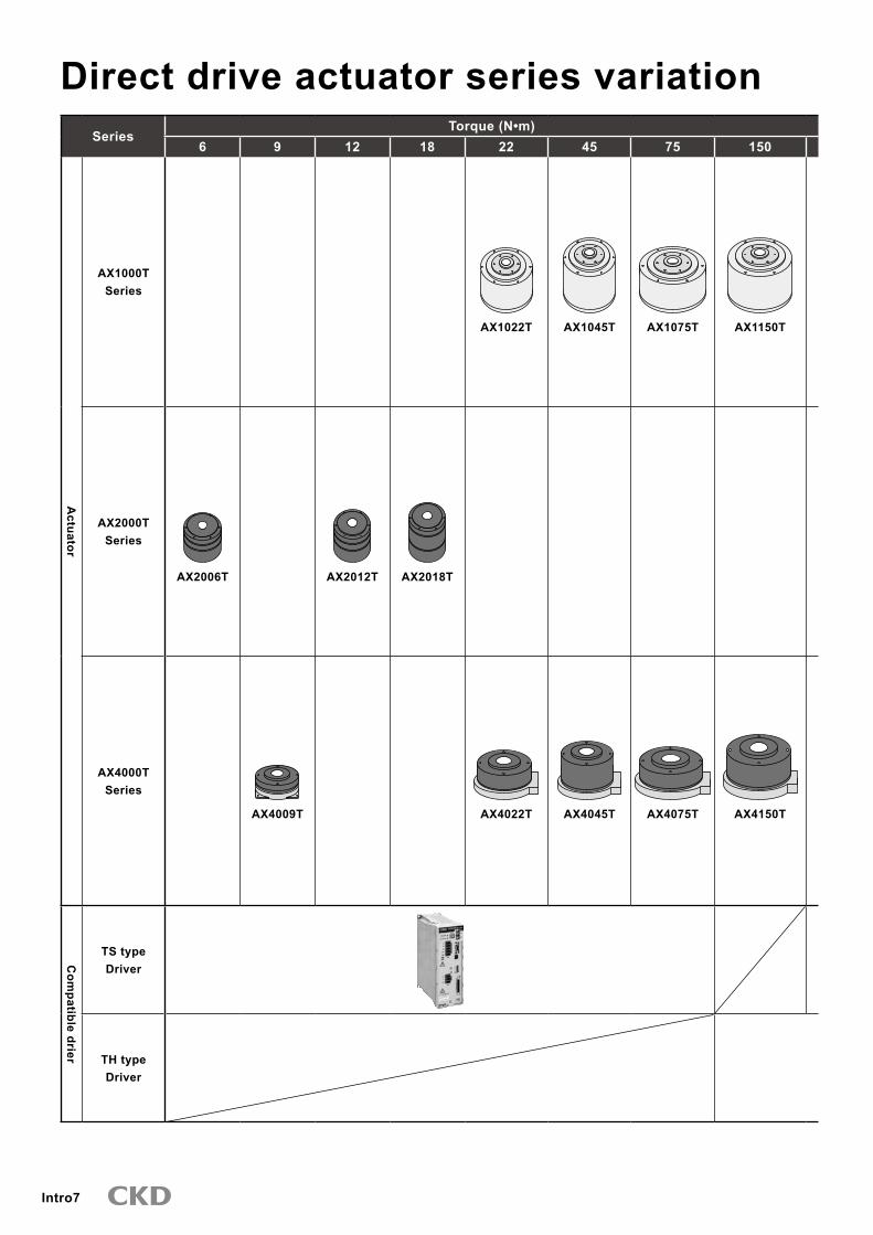
Direct drive actuator series variationSeries
Torque (N•m)6 9 12 18 22 45 75 150
Actuator
AX1000TSeries
AX1022T AX1045T AX1075T AX1150T
AX2000TSeries
AX2006T AX2012T AX2018T
AX4000TSeries
AX4009T AX4022T AX4045T AX4075T AX4150TC
ompatible drier
TS typeDriver
TH typeDriver

Intro8
Torque (N•m) Index accuracy
(sec.)Repeatability
(sec.) Features Applications Page210 �00 500 1000
AX1210T
±15 ±5
High precision model with indexing accuracy and low displacementHigh speed rotation (AX1022TS: 240rpm,AX1045TS:240rpm, AX1075TS:140rpm, AX1150TS:120rpm, AX1210TS:120rpm)
Precision measurmentTurntableInspection machineAssembly machine
1to6
±�0 ±5
High speed rotation (�00rpm)Small diameter and low profileLarge diameter of the hollow hole (Φ30)
P&PTurntableAssembly machine
7to10
AX4�00T AX4500T AX410WT
±�0 ±5
High speed rotation(AX4009TS: 240rpm,AX4022TS:240rpm, AX4045TS:240rpm, AX4075TS:140rpm)Capable of handling load of large moment of inertiaHollow diameter is wide large size option.
TurntableInspection machineAssembly machineP&P
11to28
One driver can operate actuators of any size that are compatible.The controller function enables the actuator's rotation angle, movement time and timer, etc., to be set as desired with an NC program.Data is exchanged with an external PLC using M code output, etc.
TS type;29 to �4
TH type; 29 to �4
Cable
AX
1000TA
X2000T
AX
4000TA
X0170H
AX
9000TSA
X9000TH
Applications Page: 41Safety precautions : Intro 9
Related parts model no. table Page: �9Selection guide Page: 4�

Intro9
Always read this section before starting use.
Safety precautions
When designing and manufacturing devices using direct drive actuator, the manufacturer has an obligation to manufacture a safe device, and to check that the safety of the device's mechanical mechanism and the system operated by the electrical control that controls the device is secured. It is important to select, use, handle, and maintain the product appropriately to ensure that the CKD product is used safely.Observe warnings and precautions to ensure device safety.Check that device safety is ensured, and manufacture a safe device.
WARNING This product is designed and manufactured as a general industrial machine part.It must be handled by an operator having sufficient knowledge and experience in handling.
Use this product in accordance of specifications.This product must be used within its stated specifications. It must not be modified or machined.This product is intended for use as a general-purpose industrial device or part. It is not intended for use outdoors or for use under the following conditions or environment.(Note that this product can be used when CKD is consulted prior to use and the customer consents to CKD product specifications. The customer must provide safety measures to avoid risks in the event of problems.)
Use for special applications including nuclear energy, railway, aircraft, marine vessel, vehicle, medicinal devices, devices coming into contact with beverages or foodstuffs, amusement devices, emergency cutoff circuits (cutoff, open, etc.), press machines, press circuits or safety devices.
Use for applications where life or assets could be adversely affected, and special safety measures are required.
Observe association standards and regulations, etc., to ensure safe device design.
Do not remove devices until safety is confirmed.Inspect and service the machine and devices after confirming safety of the entire system related to this product.
Note that there may be hot or charged sections even after operation is stopped. Before starting device inspection or maintenance, turn off device power and other power to related devices, release compressed air, and check leakage current.
Observe the Instruction Manual and Precautions for each product to prevent accidents.
Do not rotate the actuator outputs shaft by 30 rpm or more while power is off.The driver could fail or electrical shock result from actuator power generation.
If the servomotor is turned off (including emergency stop or alarm) or brakes are turned off while a rotational force, such as gravity is applied, the output shaft may rotate by rotational force.Conduct these operations flat where rotational force is not applied, or confirm safety before starting.
Unexpected movement may occur during gain adjustment or test operation, so keep hands, etc., away from the output shaft. When conducting operations with the actuator is not visible, confirm before starting that it is safe even if the output shaft turns.
The brakes of the type with brake do not necessarily hold the outputs shaft completely in all situations.When safety must be ensured, such as in maintenance with an application that rotates the output shaft in unbalanced mode, or when stopping the machine for a long time, it may not be sufficient to stop the shaft with brakes alone. Use the system flat or provide a mechanical lock.
It may take several seconds to stop in an emergency, depending on rotation speed and load.
Observe the precautions to prevent electrical shock.High voltage is supplied to the terminal block at the driver's front panel. Install the enclosed terminal cover before operation. Do not touch the terminal block while power is on.Even after the power is turned off, a high voltage is applied until the charge accumulated in the internal capacitor is discharged. Wait at least five minutes after turning the power off before touching these sections.
When working with the side cover off, such as for maintenance and inspection or changing driver switches, turn the power off to prevent damages and injuries caused by electrical shock from high voltages.
Do not connect or disconnect connectors while power is on. Misoperation, faults, or electrical shock may occur.
Before restarting a machine or system, check that measures are taken so that parts do not come off.

Intro10
Install an over current protection component.
The precautions are ranked as "DANGER", "WARNING" and "CAUTION" in this section.
Note that some items described as “CAUTION” may lead to serious results depending on the situation.In any case, important information that must be observed is explained.
DANGER: When a dangerous situation may occur if handling is mistaken leading to fatal or serious injuries, or when there is a high degree of emergency to a warning.
WARNING: When a dangerous situation may occur if handling is mistaken leading to fatal or serious injuries.
CAUTION When a dangerous situation may occur if handling is mistaken leading to minor injuries or physical damage.
Observe precautions on the pages that follow to prevent accidents.
Wire according to "JIS B 9960-1: 2008 Safety of Machinery - Electrical Equipment of Machines - Part 1 : General Requirements", and install an overcurrent protection device (such as molded case circuit breakers and circuit protectors) to the main•control power (terminal gland no. L1, L2, L3, L1C, L2C) and power supply for I/O (connector no. CN3-DV24V)
(Translation of an excerpt from JIS B9960-1 7.2.1 general requirements)Overcurrent protection shall be provided in cases where the circuit current in a machine (electrical equipment) can exceed the lesser of either the rating of a component or allowable ampacity of the conductor. Ratings or settings to be assigned are set in 7.2.10.
WARRANTYScope of warranty
Conditions related to the warranty term and scope are as follows:
1. Term of warrantyThis product comes with a 1 year warranty from delivery. (this warranty is effective if the product is not operated for more than 8 hours a day. The warranty will expire if the product reaches its durability shown below)Durability (direct drive actuator)Absodex brake with air brake, piston packing, valves
2. Scope of warrantyIf any faults found to be the responsibility of CKD occur during the above warranty term, the part shall be repaired immediately by CKD free of charge.Note that the following faults are excluded from the warranty term:
Product abuse/misuse contrary to conditions/environment recommended in its catalogs/specifications. Faults caused by careless or incorrect handling, or improper control. Faults caused by factors other than delivered parts. Faults caused by improper product use. Faults due to modifications to the product structure , performance, or specifications by a party other than CKD after the product is delivered, or faults caused by repairs not designated by CKD.
Damage that could have been avoided if the user's machine or equipment had functions and structures, etc., considered normal within the industry.
Failure due to causes not foreseeable with the technology at the time of delivery. Failure due to fires, earthquakes, water damage, lightning, other acts of nature, acts of God, pollution, salt damage, gas damage, abnormal voltage, or other external forces.
The warranty here refers to the warranty of the actually delivered product, and does not include any damage resulting from a fault in the delivered product.
�. Warranty for exported products(1) Product returned to our factories or companies/factories designated by CKD will be repaired. CKD is
not liable for the costs and engineering required that is required for the return.
This warranty specifies basic conditions. If warranty details in individual specification drawings or specifications differ from these warranty conditions, specification drawings or specifications shall take priority.

Intro11
Design & SelectionCAUTION The actuators and drivers are not waterproof. Provide waterproofing for use in places where water or oil could come in contact with these devices. Current leakage and faults could occur if swarf or dust get onto the actuator or driver. Check that these do not come in contact with devices. Turning the main power on and off frequently may cause damage to the element in the driver. The output axis may move from the holding position even
without an external force if the power or servo is turned off. Optional magnetic brakes are used to enhance holding rigidity during output shaft stoppage.Do not use these brakes to brake or stop a rotating output shaft. The actuator and driver do not have a rust proof guarantee. Equipment in which direct drive actuators are installed should have sufficient rigidity to realize full direct drive actuator performance. If the load equipment or frame's mechanical unique vibration is relatively low (200 to �00Hz or less), resonance could occur in the direct drive actuator and load equipment or frame. Secure the rotary table and main unit installation bolts, and ensure sufficient rigidity without loosening, etc. [Fig. 1]
Installing the actuator [Fig.1]
Dial plate fixing
Mounting base
Gain must be adjusted based on load table size, etc.[Fig.2] Even when the direct drive actuator is not directly installed, it should be installed on a highly rigid frame. [Fig.2]
[Fig.2] Mounting the actuator
When extending the outuput shaft, refer to table 1 as a reference for deciding the extended shaft diameter and length. Also, install a dummy inertia using fig. � as a reference.
[Table1] Reference of diameter for extended output shaft
Max. torque[N・m]
Shaft extension(mm)50 100 200 �00 500
6 φ35 φ40 φ46 φ50 φ609,12 φ40 φ46 φ55 φ60 φ70
18,22 φ45 φ55 φ65 φ70 φ8045 φ55 φ65 φ75 φ85 φ9575 φ62 φ75 φ90 φ95 φ110
150 φ75 φ90 φ110 φ115 φ130210 φ80 φ95 φ115 φ125 φ140�00 φ90 φ105 φ125 φ140 φ155500 φ100 φ120 φ145 φ160 φ180
1000 φ120 φ140 φ170 φ185 φ210

Intro12
If sufficient rigidity cannot be attained, machine resonance is suppressed to some degree by installing dummy inertia as close to the actuator as possible.Examples of adding dummy inertia are shown below.
When extending the output shaft, the following dimensions apply as a guide to the extended shaft's diameter:AX2006T, AX4009T, AX2012T, AX2018T, AX□022T, AX□045T:Φ60mm and over, AX□075T, AX□150T, AX1210T, AX4300T:Φ90mm and over, AX4500T:Φ150mm and over.As a reference, dummy inertia is [load inertia] x (0.2 to 1). [Fig.�]
[Fig.�] Example 1. for dummy inertia installation
Dummy inertia
When coupling with belts, gears or spline or when joining with a key, dummy inertia should be [load inertia] x (0.5 to 2).If speed changes with belts or gears, use load inertia as the actuator output shaft conversion value, and install dummy inertia on the actuator. [fig.4] [fig.5].
Note: Install dummy inertia as large as possible within the actuator's capacity. (Use steel with a large specific gravity).
[Fig.4] Example 2. for dummy inertia installation
Dummy inertia
Gear
[Fig.5] Example �. for dummy inertia installation
Dummy inertia
Ball spline
( )Select gears with as largediameters as possible.
Design & SelectionCAUTIONDo not place the actuator where it may contact strong magnetic field. Do not pass cables with high voltage through the central hollow hole. It may lead to malfunctioning, lower performance and damage. Use of surge protector is recommended when there is a risk of damage caused by lightning surge.

Intro1�
Design & SelectionCAUTION Connecting magnetic brakes
24 VDC (relay drive)
24 VDC (power supply for)
Surge Protector
200 VAC three phase
Blue lead wire (Not polarized)
GND
Ferrite core
Relay
Electromagnetic contactor (any)
Driver
Protection element(Included with actuator)
(Resolver cable)
Direct drive actuator Actuator body
Noise filter
(Motor cable)
Cut off machine for wiring G2
G1
SERIES
C N 1
DRIVER
C N 2
T B 1
C N 3
T B 2
POWER
CHARGE
L2
L3
L1C
L2C
L1
CN4 AC100 -115V
50/60Hz
W
V
U
CN5
- S1
BK + BK -
- S2
ABSODEX
+ S1 + S2
MON.
A B S O D E X MODEL: AX9000TS
MADE IN JAPAN
+25A1+25A1+25A1+25A1+25A1+25A1+25A1
CKD Corporation
1) Do not use magnetic brakes to stop or control the rotating output shaft.2) The driver will be damaged if the driver's BK+ and BK- and magnetic brakes are directly connected.�) When connecting the following inductive load, such as a relay, to the external contact, set the coil's rated voltage to 24
VDC and the rated current to 100 mA or less, and provide measures against surge current.
Recommended circuit for magnetic brakes
( ) Driv
er
BK-
BK +(not included)External contact (such as relay)
(not included)Surge countermeasures (such as diodes)(Blue Approx. 30 cm)
Electromagnetic brake lead wire
(not included)External power 24 VDC
(not included)External power 24 VDC
CRProtection element
Electr
omag
netic
brake
Attached toactuator
Driv
er
BK-
BK +(not included)Relay (4 pole)
(not included)Surge such as countermeasures (such as diode)(Approximate blue 30cm)
Lead wire
(not included)External power 24 VDC
(not included)External power 24 VDC
CR
Protection element
Electr
omag
netic
brake
( )Attached toactuator
• Relay contact serial connection
Operation method1. Control with NC program (M68, M69)
When the "M68" code is executed, BK+ to BK- will not be energized (brakes are applied), and when the "M69" code is executed, BK+ to BK- will be energized (brakes are released).
2. Control with brake release input (I/O connector/18 pin)If brake release is input while the brakes are applied, BK+ to BK- will be energized (brakes are released).
If magnetic brakes are frequently turned on and off, use a solid-state relay (SSR) for the external contact.Recommended model G�NA-D210BDC5-24 (OMRON)Refer to the SSR instruction manual before using.
Check that relay contact capacity is 10 times or more than the rated current. If less, use a multiple relay and use two or more relay contacts serially. Reed life can be extended.
When passing a shaft through the hollow hole in the type with magnetic brakes, use a non-magnetic material (SUS�0�, etc.).If magnetic material (S45C, etc.) is used, the shaft will be magnetized. This could cause iron powder to stick on the device or the peripheral devices to be affected by the magnetic properties.Note that around the magnetic brakes, iron powder, etc., could be attracted by the magnetic properties, or measuring instruments, sensors and other devices could be affected.Refer to the Technical Documents of the Absodex AX Series TS,TH type driver for other precautions.

Intro14
Safety precautions
Always read this section before starting use.
Labor saving mechanisms warning
Installation & AdjustmentCAUTION Connect the enclosed cable between the actuator and driver. Check that excessive force is not applied and the cable is not damaged. Do not modify the enclosed cable (change the length or material) because this could cause malfunction or faults. Connect the correct power supply. Connecting a undesignated power supply could cause faults. Wait at least 5 seconds after turning power off before turning it on again. Securely fix the direct drive actuator to the machine, and securely install loads such as the table before adjusting gain. Confirm that no interference occurs and that safety is secured even when f lexible sections are rotated. Do not tap the output shaft with a hammer, nor assemble it forcibly. Failure to observe this would prevent the expected accuracy or functions, and could cause faults. Do not place strong magnetic fields such as rare earth magnets near the actuator. Failure to observe th is may cause fa i lures to mainta in expected accuracy. The actuator may become hot depending on operating conditions. Provide a cover, etc., so that it will not be touched by accident. The ac tua tor may become hot depend ing on operating conditions. Do not drill holes into the actuator. Contact CKD when machining is required. Do not get on the actuator or flexible parts such the rotary table on the actuator during maintenance, etc.
Compatible typeIf the actuator and driver are combined mistakenly after program input (parameter setting), alarm � wi l l go off . Check the actuator and driver combination.Note: Alarm � is to prevent malfunction if the
actuator and driver combination differ from when the program was input. Alarm � is reset when the program and parameters are input again.
If operation is started with an incorrect actuator and driver combination after the program is input (after parameter setting), it may result in malfunctions and damages.When changing the cable length or type, order the cable separately.Actuator may catch fire if an incompatible driver is connected.
When using a circuit breaker, select one that has higher harmonic measures for inverter use. The position of the output shaft in the actuator dimension drawing does not indicate the actuator's origin. When using it at the output shaft shown in dimension drawings, the origin must be adjusted to the origin offset. The body outlet cable on AX4009T and AX200T series can not be moved. Always fix it at the connector section so that it will not move. Also, refrain from applying excess force onto the cable or pulling on the cable since it may damage it. Refer to the technical documents of the Abxodex AX Series TS, TH type for other precautions and conformity to standards.
During Use & MaintenanceCAUTION Do not disassemble the actuator, because this may compromise expected functions and accuracy. Any modification to the resolver could cause critical damage. When testing withstand voltage of the machine or equipment containing the direct drive actuator, disconnect the power cable for the driver and check that the voltage is not applied to the driver. Failure to observe this could result in faults.
If alarm "4" (actuator overload: electronic thermal) goes off, wait for the actuator temperature to drop before restarting.Alarm "4" could occur in the cases below. Remove the cause before resuming use.
Resonance or v ib ra t ion : Ensure su f f i c ien t installation rigidity.Tact or speed: Increase movement t ime or stopping time.Structure that locks the output shaft: Add M68, M69 commands.
Actuator coordinates are recognized after power is turned on so check that the output shaft does not move for several seconds after power is turned on. Refer to the technical documents of the Abxodex AX Series TS, TH type for other precautions and conformity to standards.

1
Actuator specifications
Direct drive actuator
AX1000T Series actuatorHigh precision specification with high indexing accuracy and output shaft run out
Max. torque: 22, 45/75/150/210N•m
Descriptions AX1022T AX1045T AX1075T AX1150T AX1210T
Maximum output torque N•m 22 45 75 150 210Continuous output torque N•m 7 15 25 50 70Max. rotation speed rpm 240 (Note 1) 140 (Note 1) 120 (Note 1)Allowable axial load N 600 2200Allowable moment load N•m 19 �8 70 140 170Allowable radial load N 1000 4000Output shaft moment of inertia kg/m2 0.00505 0.00790 0.0�660 0.05820 0.09280Allowable load moment of inertia kg/m2 0.6 0.9 4.0 6.0 10.0Index accuracy (Note �) sec. ±15Repeatability (Note �) sec. ±5Output shaft friction torque N•m 2.0 8.0Resolver resolution P/rev 540672Motor isolations class Class FMotor withstanding voltage 1500 VAC for one minuteMotor isolation resistance 10MΩ 500 VDC and overWorking ambient temperature range 0 to 45°CAmbient humidity range 20 to 85%RH with no dew condensationStorage ambient temperature range -20 to 80°CStorage ambient humidity range 20 to 90%RH with no dew condensationAtmosphere No corrosive gas, flammable or powder dustWeight kg 8.9 12.0 2�.0 �2.0 44.0Run out of output shaft mm 0.01Run out of output shaft surface mm 0.01Protection IP20
Note1: The speed must be kept below 80rpm during continuous rotation. Contact CKD for CE certification requirements.Note2: Refer to "Technical explanations" on page 49 for the details on index accuracy and repeatability.Note�: The max ambient temperature is 40°C if used as an UL certified product.
Always read the precautions on Intro 9 to 1� before starting use.

2
How to orderAX1000T Series
AX
1000TA
ctuator
H Interface specifications
H Interface specifications
How to order
G Dowel hole Note 4
E Cable length Note �
B Driver type Note 1
Model no.
A Size (max. torque)
D Connector direction
Note on model no. selectionNote 1: Use the table below to select the appropriate driver.
Driver-power voltage table
DriverType
Model
TS type driver TH type driverThree phase/single phase
200 to 2�0 VAC
Single phase 100 to 115 VAC
Three phase 200 to 2�0 VAC
AX1022T Blank Note 2 J1AX1045T Blank Note 2 J1AX1075T Blank Note 2AX1150T BlankAX1210T Blank
Note 2: Single phase 200 to 2�0 VAC is available for models with a torque of 45N•m or less.
Note �: Flexible cableRefer to page �5 for the dimensions of the cable.
Note 4: C If the mounting base is "B" (with blackened mounting base), "P2" and "P�" can not be selected.
Model Model no. of options
AX1 DM04022 B J1 P1 U0CTS
Symbol DescriptionsA Size (max. torque)022 22 N•m045 45 N•m075 75 N•m150 150N•m210 210N•m
B Driver typeTS TS type driverTH TH type driver
C Mounting baseBlank Standard (without mounting base)
B With blackened mounting base
E Cable lengthDM02 2mDM04 4m (standard length)DM06 6mDM08 8mDM10 10mDM15 15mDM20 20m
G Dowel holeBlank Standard (without dowel hole)
P1 1 on topP2 1 on bottomP� 1 each on both top and bottom
F Driver power voltageRefer to the Driver-power voltage table on the left.
F Driver power voltage Note 1
D Connector directionBlank Standard (connector horizontal installation)
C Connector bottom installation
C Mounting base
( )
Discrete actuator body model no. Discrete driver model no. Discrete cable model no.AX1 T C P1 B AX9000TS
AX9000THU0U0
AX9000TS J1 U0
AX CBLM5 DM04Three phase 200 to 2�0 VAC
Single phase 100 to 115 VAC
A Size
C Mounting base
D Connector direction
G Dowel hole
E Cable changeNote: "04" for cable
length 4 m
Motor cable
AX CBLR5 DM04Resolver cable
Set model no. (actuator, driver or cable)
H Interface specificationsU0 Parallel I/O (NPN specifications)U1 Parallel I/O (PNP specifications)(Coming soon)U2 CC-LinkU� PROFIBUS-DPU4 DeviceNet
*Custom orders are not CE, UL/cUL, RoHS certified. Consult with CKD for details.

�
AX1000T Series
F
F
L
(Note) moment load
M(N m)=F(N)×L(m)M: Moment loadF: LoadL: Distance from output shaft center
M(N m)=F(N)×(L+0.02)(m)M: Moment loadF: LoadL: Distance from output shaft flange
(Fig. a) (Fig. b)
L
Speed/max. torque characteristicsAX1022TS AX1045TS
AX1150TH
AX1210TH
*This graph shows the characteristics under 3 phase AC200V
Continuousmovementrange
*This graph shows the characteristics under 3 phase AC200V
Continuousmovementrange
*This graph shows the characteristics under 3 phase AC200V
Continuousmovementrange
*This graph shows the characteristics under 3 phase AC200V
Continuousmovementrange
*This graph shows the characteristics under 3 phase AC200V
Continuousmovementrange

4
DimensionsAX1000T Series
AX
1000TA
ctuator
DimensionsAX1022T AX1045T
(Option)
For mounting dial plate
(Cable bending range)
(Including hollow section)Rotating section
Mounting base
6-Φ7 (straight)
6-M6 depth 11 (straight)
P.C.D.140
P.C.D.70
6-M6 depth 9 (straight)
P.C.D.180 185
78
19.5
Rotating section(Including hollow section)
Φ40h7
Φ25
Φ22
Φ24
Φ120h7
Φ200
A
2322
91 103
5128
11
55
5
102 22
Φ160
Φ152
Φ120
Φ85
12
(Option)Φ6H7 depth 8
35
15°
0.04 A
45°
P.C.D.140
6-M6 depth 9 (straight)
Not available if the optional base is installed.Φ6H7 depth 8 (option) 0.04
B
70
(32)
(27)
(Option)
For mounting dial plate
(Cable bending range)
(Including hollow section)Rotating section
Mounting base
6-Φ7 (straight)
6-M6 depth 11 (straight)P.C.D.140
P.C.D.70
6-M6 depth 9 (straight)
P.C.D.180 185
78
19.5
Φ160
A
Φ152Φ120Φ85
Φ25
Φ22
Φ24
Φ120h7
Φ200
102 22
Φ40h7
Rotating section(Including hollow section)
23 812
613
8
55
11
12
12
22
5
5
(Option)Φ6H7 depth 8
35
15°
0.04 A
45°
P.C.D.140
6-M6 depth 9 (straight)
Not available if the optional base is installed.Φ6H7 depth 8 (option) 0.04
B
70
(32)
(27)
Note 1) The origin of the actuator may differ from the dimensions shown above. Origin can be configured randomly using the origin offset function.

5
AX1000T Series
DimensionsAX1075T AX1150T
(Cable bending range)
For mounting dial plate
(Option)
(Including hollow section)
185
P.C.D.265
P.C.D.100
P.C.D.220
Mounting base
6-M8 depth 12 (straight)
6-Φ9 (straight)
6-M8 depth 14 (straight)
78
20.7
Rotating section
Φ8H7 depth 10 (option)
50
15°
0.04 A
Rotating section (Including hollow section)
Φ70h7 Φ40
Φ37
Φ39
Φ200h7 Φ290
A
29
37
100
115
15
12 8
14
55
8
15
146.5 22
Φ242 Φ234 Φ200 Φ125
45°
Φ8H7 depth 10 (option) Not available if the optional base is installed.
P.C.D.220
0.04 B
110
6-M8 depth 12 (straight)
17
(32)
(2
7)
(Cable bending range)
(For mounting dial plate)
(Option)
(Including hollow section)
185
P.C.D.265
P.C.D.100
P.C.D.220
Mounting base
6-M8 depth 12 (straight)
6-Φ9 (straight)
6-M8 depth 14 (straight)
78
Rotating section
Φ8H7 depth 10 (option)
50
15°
0.04 A
15
Rotating section (Including hollow section)
Φ70h7 Φ40
Φ37
Φ39
Φ200h7 Φ290
A
29 2-M4
GND for mounting
37
145
160
15
12 8
14
55
8
146.5 22
Φ242 Φ234 Φ200 Φ125
45°
Φ8H7 depth 10 (option) Not available if the optional base is installed.
P.C.D.220
0.04 B
110
6-M8 depth 12 (straight)
20.7
17
(32)
(2
7)
Note 1) The origin of the actuator may differ from the dimensions shown above. Origin can be configured randomly using the origin offset function.

6
Standard dimensions and dimensions with optionsAX1000T Series
AX
1000TA
ctuator
Dimensions with optionsBottom connector (C)AX1022T/AX1045T
DimensionsAX1210T
AX1075T/AX1150T/AX1210T
(Cable bending range)
For mounting dial plate
(Option)
(Including hollow section)
185
P.C.D.265
P.C.D.100
P.C.D.220
Mounting base
6-M8 depth 12 (straight)
6-Φ9 (straight)
6-M8 depth 14 (straight)
78
Rotating section
Rotating section (Including hollow section)
Φ242 Φ234 Φ200 Φ125 Φ70h7
Φ40
29
15
190
37
8
55
14
15
205
8
Φ39 2-M4 GND for mounting
Φ37
Φ200h7 146.5 22
Φ290
A
45°
Φ8H7 depth 10 (option) Not available if the optional base is installed.
P.C.D.220
0.04 B
110
6-M8 depth 12 (straight)
Φ8H7 depth 10 (option)
50
15°
0.04 A 20.7
17
(32)
(2
7)
Φ25
Φ119
Φ22
37.5
30(1
1)
90°
45°
Not available if the optional base is installed.Φ6H7 depth 8 (option)
6-M6 depth 9 (straight)
0.04B
70
P.C.D.140
Φ24
Φ40
Φ198
2-M4 GND for mounting(AX1150T and AX1210T only)
60
Φ55
35(1
4)
90°
P.C.D.220 45°
Φ8H7 depth 10 (option)Not available if the optional base is installed.
0.04B
1106-M8 depth 12 (straight)
Φ39
Φ37
Note 1) The origin of the actuator may differ from the dimensions shown above. Origin can be configured randomly using the origin offset function.

7
Actuator specifications
Direct drive actuator
AX2000T SeriesHigh speed rotation(max. 300rpm). low profile, large hollow diameter (Φ30)
Max. torque: 6/12, 18 N•mCompatible drier: TS type driver
Descriptions AX2006T AX2012T AX2018T
Maximum output torque N•m 6.0 12.0 18.0Continuous output torque N•m 2.0 4.0 6.0Max. rotation speed rpm �00 (Note 1)Allowable axial load N 1000Allowable moment load N•m 40Output shaft moment of inertia kg/m2 0.00575 0.00695 0.00910Allowable load moment of inertia kg/m2 0.� 0.4 0.5Index precision (Note 2) sec. ±�0Repeatability (Note 2) sec. ±5Output shaft friction torque N•m 0.6 0.7Resolver resolution P/rev 540672Motor isolation class Class FMotor withstanding voltage 1500 VAC for one minuteMotor isolation resistance 10MΩ 500 VDC and overAmbient temperature range 0 to 45°CAmbient humidity range 20 to 85%RH with no dew condensationStorage ambient temperature range -20 to 80°CStorage ambient humidity range 20 to 90%RH with no dew condensationAtmosphere No corrosive gas, flammable or powder dustWeight kg 4.7 5.8 7.5Run out of output shaft mm 0.0�Surface run out of output shaft mm 0.0�Protection IP20Note1: The speed must be kept below 80rpm during continuous rotation.Note2: Refer to "Technical explanations" on page 49 for the details on index accuracy and repeatability.Note�: The max ambient temperature is 40°C if used as a UL certified product.
Speed/max. torque characteristics
Always read the precautions on Intro 9 to 1� before starting use.
(Note)Moment load
M(N m)=F(N)×L(m)M Moment loadF LoadL Distance from output shaft center
M(N m)=F(N)×(L+0.02)(m)M Moment loadF LoadL Distance from output shaft flange
AX2006TS AX2012TS
AX2018TS*This graph shows the characteristics under 3 phase AC200V
Continuousmovementrange
*This graph shows the characteristics under 3 phase AC200V
Continuousmovementrange
*This graph shows the characteristics under 3 phase AC200V
Continuousmovementrange

8
How to orderAX2000T Series
AX
2000TA
ctuator
H Interface specifications
H Interface specifications
( )
How to order
G Body surface treatment Note �
E Driver power voltage Note 1
F Dowel hole Note 4, Note 5
B Driver type
Model no.
A Size (max. torque)
D Cable length Note 2
AX2 018 DM04 J1TS BS P1 U0S
Model Model no. of options
Symbol Descriptions
A Size (max. torque)006 6 N•m012 12 N•m018 18 N•m
B Driver typeTS TS type driver
C Mounting base (can not be used with a dowel hole P2, P�.)Blank Standard (without mounting base)
B With blackened mounting base
BS Electroless nickel plating, surface treatment mounting base Use with body surface treatment S.
E Driver power voltageRefer to a the left mentioned driver-power voltage table.
F Dowel holeBlank Standard (without dowel hole)
P1 1 on topP2 1 on bottomP� 1 each on both top and bottom
G Body surface treatmentBlank Standard (blackening treatment)
S Electroless nickel plating
Note on model no. selectionNote 1: Use the table below to select the appropriate driver.
Driver-power voltage tableDriver
TypeModel
TS type driverThree phase and
single phase200 2�0 to VAC
Single phase100 115 to
VACAX2006T Blank J1AX2012T Blank J1AX2018T Blank J1
Note 2: The cable is a flexible cable.Refer to page �5 for dimensions of a cable. The body outlet cable is not a flexible cable.
Note �: Designate surface treatment and mounting base surface treatment with C and H . By selecting the optional electroless nickel plating, higher resistance to rusting can be expected.
Note 4: "P2" and "P�" cannot be selected if "B" with blackened mounting base or "BS" electroless nickel plating surface treatment mounting base is designated for C Mounting base.
Note 5: Additionally machined sections may not have a treated surface.
Set model no.(actuator, driver, cable)
*Custom orders are not CE, UL/cUL, RoHS certified. Consult with CKD for details.
Discrete actuator body model no. Discrete driver model no. Discrete cable model no.AX2 T SP1B AX9000TS U0
AX9000TS J1 U0
AX CBLM6 DM04Three phase 200 to 2�0 VAC
Single phase 100 to 115 VACA Size
C Mounting base G Body surface treatment
F Dowel hole
D Cable changeNote: "04" for cable
length 4 m
Motor cable
Resolver cableAX CBLR6 DM04
D Cable lengthDM02 2mDM04 4m (standard length)DM06 6mDM08 8mDM10 10mDM15 15mDM20 20m
H Interface specificationsU0 Parallel I/O (NPN specifications)U1 Parallel I/O (PNP specifications)(Coming soon)U2 CC-LinkU� PROFIBUS-DPU4 DeviceNet
C Mounting base Note �, 4

9
AX2000T Series
AX2006T
Dimensions
For mounting dial plate
Φ30.5
P.C.D.60
Φ80h8
Φ30H8 43
.5
(Φ30H8
range)
4
19.5 28
Φ90h7
Cable position
Recommended positions for connector hole formounting motor base
22
35
P.C.D.100
Fixed section
6-M5 depth 10 (straight)
Mounting base (option)
95
95
Φ5H7 depth 8 (option) 4-Φ7
Φ110
115
110
3.5
Rotating section (5
)
Φ150
Φ40
12.5
1 12
0
45°
Fixed section
4-M6 depth 12 (straight)
40.5×21
110
AX center
The
500m
m o
utle
t cab
le is
not
flex
ible
. (N
ote)
(Note): Fix the end of the cable sheath when bending repeatedly.
42
(Note): Min. bending rangeof outlet cable is 30mm.
Fixed section
0.04 A
A
50
B
30
Φ6H7 depth 8 (option) Not available if the optional base is installed.
0.04 B
(Fixed shaft inner diameter)
(Option base inner diameter)
(Fixed shaft inner diameter)
For mounting dial plate
(Option base inner diameter)
A
B
Φ30.5
P.C.D.60
Φ80h8
Φ30H8
43.5
(Φ3
0H8 ran
ge)
4
19.5 28
Φ90h7
Cable position Recommended positions for connector hole formounting motor base
22
35
P.C.D.100
Fixed section
6-M5 depth 10 (straight)
Mounting base (option)
95
95
50
30
Φ5H7 depth 8 (option) 4-Φ7
Φ110
95
90
3.5
Rotating section
(5)
Φ150
Φ40
12.5
1 10
0
45°
Fixed section
4-M6 depth 12 (straight)
Φ6H7 depth 8 (option) Note: Not available if optional base is installed
40.5×21
110
AX center
The
500m
m o
utle
t cab
le is
not
flex
ible
. (N
ote)
Note: Fix the end of the cable sheath when bending repeatedly.
42
Fixed section
0.04 A
0.04 B
(Fixed shaft inner diameter)
(Fixed shaft inner diameter) (Fixed shaft inner diameter) (Note): Min. bending rangeof outlet cable is 30mm.
AX2012T
Note 1) The origin of the actuator may differ from the dimensions shown above. Origin can be configured randomly using the origin offset function.

10
DimensionsAX2000T Series
AX
2000TA
ctuator
DimensionsAX2018T
For mounting dial plate
Φ30.5
P.C.D.60
Φ80h8
Φ30H8
43.5
(Φ3
0H8 ran
ge)
4
19.5 28
Φ90h7
Cable position
Recommended positions for connector hole formounting motor base
22
35
P.C.D.100
Fixed section
6-M5 depth 10 (straight)
Mounting base (option)
95
95
Φ5H7 depth 8 (option) 4-Φ7
Φ110
150
145
3.5
Rotating section
(5)
Φ150
Φ40
12.5
1
155
45°
Fixed section
4-M6 depth 12 (straight)
40.5×21
110
AX center
The
500m
m o
utle
t cab
le is
not
flex
ible
. (N
ote)
(Note): Fix the end of the cable sheath when bending repeatedly.
42
Fixed section
(Note): Min. bending range of outlet cable is 30mm.
0.04 A
A
50
B
30
Φ6H7 depth 8 (option) Not available if the optional base is installed.
0.04 B
(Fixed shaft inner diameter)
(Option base inner diameter) (Option base inner diameter)
(Fixed shaft inner diameter)
Note 1) The origin of the actuator may differ from the dimensions shown above. Origin can be configured randomly using the origin offset function.

11
Actuator specifications
Direct drive actuator
AX4000T SeriesResistance to load of large moment of inertiaWide variety of optionsEasier to pipe and wire with large inner diameter
Max. torque: 9/22, 45/75 N•mCompatible drier: TS type driver
Descriptions AX4009T AX4022T AX4045T AX4075T
Maximum output torque N•m 9 22 45 75Continuous output torque N•m � 7 15 25Max. rotation speed rpm 240 (Note 1) 140 (Note 1)Allowable axial load N 800 �700 20000Allowable moment load N•m 40 60 80 200Output shaft moment of inertia kg/m2 0.009 0.0206 0.0268 0.1490Allowable load moment of inertia kg/m2 0.�5 (1.75) (Note 2) 0.60 (�.00) (Note 2) 0.90 (5.00) (Note 2) 5.00 (25.00) (Note 2)Index accuracy (Note 4) sec. ±�0Repeatability (Note 4) sec. ±5Output shaft friction torque N•m 0.8 �.5 10.0Resolver resolution P/rev 540672Motor isolation class Class FMotor withstanding voltage 1500 VAC for one minuteMotor isolation resistance 10MΩ 500 VDC and overAmbient temperature range 0 to 45°CAmbient humidity range 20 to 85%RH with no dew condensationStorage ambient temperature range -20 to 80°CStorage ambient humidity range 20 to 90%RH with no dew condensationAtmosphere No corrosive gas, flammable or powder dustWeight kg 5.5 12.� 15.0 �6.0Brake total weight when set kg — 16.4 19.� 54.0Run out of output shaft mm 0.0�Run out of output shaft surface mm 0.05Protection IP20Note1: The speed must be kept below 80rpm during continuous rotation.Note2: When using within the load conditions shown in the parenthesis, set parameter 72(multiplier for integral gain) to 0.�(reference value).Note�: Consult CKD each time when using parameter 72 (multiplier for integral gain) during continuous rotation.Note4: Refer to "Technical explanations" on page 49 for the details on index accuracy and repeatability.Note5: Max. ambient temperature is 40°C when used as a UL certified product.
Specifications (option)
Refer to the precautions on Intro 9 to 1� before starting use.
Compatible modelsDescriptions AX4022T/AX4045T AX4075T
Type Non-backlash dry non-excitation operation typeRated voltage V DC24VPower supply wattage W �0 55Rated current A 1.25 2.�0Static friction torque N•m �5 200Armature release time (brake on) msec 50 (reference value) 50 (reference value)Armature suction time (brake off) msec 150 (reference value) 250 (reference value)Holding precision Minute 45 (reference value)Max. cycle rate Time/min. 60 40Note 1: When the output shaft is rotating, rubbing noise may be generated at the electromagnetic brake's disk and fixing section.Note 2: When moving after brakes are turned OFF, the delay time parameter must be changed based on armature suction time.Note �: This is a nonbacklash type, but it may be hard to hold a set position if load is applied in the direction of rotation.Note 4: When electromagnetic brakes function, the armature may contact the magnetic brake's fixed section and generate noise.Note 5: Brakes are manually released by alternately screwing screws into manual release taps (� positions). Lightly tighten
screws until they stop, then turn them another 90°. When finished with manual release, remove the three bolts immediately and apply brakes.
12
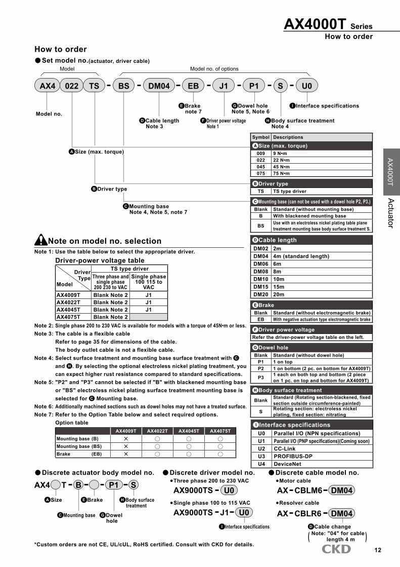
How to orderAX4000T Series
AX
4000TA
ctuator
( )D Cable changeNote: "04" for cable
length 4 m
How to order
C Mounting base Note 4, Note 5, note 7
G Dowel holeNote 5, Note 6
E Brake note 7
H Body surface treatment Note 4
B Driver type
Model no.
A Size (max. torque)
D Cable length Note �
Note on model no. selectionNote 1: Use the table below to select the appropriate driver.
Driver-power voltage tableDriver
TypeModel
TS type driverThree phase and
single phase200 2�0 to VAC
Single phase100 115 to
VACAX4009T Blank Note 2 J1AX4022T Blank Note 2 J1AX4045T Blank Note 2 J1AX4075T Blank Note 2
Note 2: Single phase 200 to 2�0 VAC is available for models with a torque of 45N•m or less.Note �: The cable is a flexible cable
Refer to page �5 for dimensions of the cable.The body outlet cable is not a flexible cable.
Note 4: Select surface treatment and mounting base surface treatment with C
and H . By selecting the optional electroless nickel plating treatment, you can expect higher rust resistance compared to standard specifications.
Note 5: "P2" and "P�" cannot be selected if "B" with blackened mounting base or "BS" electroless nickel plating surface treatment mounting base is selected for C Mounting base.
Note 6: Additionally machined sections such as dowel holes may not have a treated surface.Note 7: Refer to the Option Table below and select required options.
Option tableAX4009T AX4022T AX4045T AX4075T
Mounting base (B)Mounting base (BS)Brake (EB)
F Driver power voltage Note 1
Symbol Descriptions
A Size (max. torque)009 9 N•m022 22 N•m045 45 N•m075 75 N•m
B Driver typeTS TS type driver
C Mounting base (can not be used with a dowel hole P2, P�.)Blank Standard (without mounting base)
B With blackened mounting base
BS Use with an electroless nickel plating table plane treatment mounting base body surface treatment S.
F Driver power voltageRefer the driver-power voltage table on the left.
G Dowel holeBlank Standard (without dowel hole)
P1 1 on topP2 1 on bottom (2 pc. on bottom for AX4009T)
P� 1 each on both top and bottom (2 piece on 1 pc. on top and bottom for AX4009T)
H Body surface treatment
Blank Standard (Rotating section-blackened, fixed section outside circumference-painted)
S Rotating section: electroless nickel plating, fixed section: nitrating
E BrakeBlank Standard (without electromagnetic brake)
EB With negative actuation type electromagnetic brake
*Custom orders are not CE, UL/cUL, RoHS certified. Consult with CKD for details.
Discrete actuator body model no. Discrete driver model no. Discrete cable model no.AX4 T SP1B AX9000TS U0
AX9000TS J1 U0 AX CBLR6 DM04
Three phase 200 to 2�0 VAC
Single phase 100 to 115 VACA Size
C Mounting base
H Body surface treatment
G Dowel hole
Set model no.(actuator, driver cable)
E Brake
Motor cable
Resolver cable
AX CBLM6 DM04
AX4 022 P1DM04 U0J1EBBSTS S
Model Model no. of options
D Cable lengthDM02 2mDM04 4m (standard length)DM06 6mDM08 8mDM10 10mDM15 15mDM20 20m
I Interface specifications
I Interface specifications
I Interface specificationsU0 Parallel I/O (NPN specifications)U1 Parallel I/O (PNP specifications)(Coming soon)U2 CC-LinkU� PROFIBUS-DPU4 DeviceNet

1�
AX4000T Series
Speed/max. torque characteristics
F
F
L
(Note) moment load
M(N•m)=F(N)×L(m)M: Moment loadF: LoadL: Distance from output shaft center
M(N•m)=F(N)×(L+0.02)(m)M: Moment loadF: LoadL: Distance from output shaft flange
(Fig. a) (Fig. b)
L
Refer to the precautions on Intro 9 to 1� before starting use.
AX4009TS AX4022TS
AX4045TS AX4075TS
*This graph shows the characteristics under 3 phase AC200V
Continuousmovementrange
*This graph shows the characteristics under 3 phase AC200V
Continuousmovementrange
*This graph shows the characteristics under 3 phase AC200V
Continuousmovementrange
*This graph shows the characteristics under 3 phase AC200V
Continuousmovementrange

14

15
AX4000T Series
DimensionsAX4009T
40.5
×t21
110 35 50
of outlet cable is 30mm.(Note) Min. bending radius
Note) Do not remove. The noise resistance could drop.
146±0.03
120±
0.03
(Note): Fix the end of the cable sheath when bending repeatedly.
2-Φ6H7 (Option)
4-Φ7 Φ5H7 depth 7 (Option)
Body outlet cable length 400 mm This is not a flexible cable.
6.5
(5)
18 45
50
10
Φ170
Φ42
Φ42.5
30
Φ19.5
85
140
160
160
140
Φ150h7 Φ168
A
A 0.06
(Option dowel hole dimension)
(Opti
on do
wel h
ole di
mens
ion)
6-M5 depth 10 (straight) For mounting dial plate
Fixed section
Rotating section (including hollow section)
80
P.C.D.160
Note 1) The origin of the actuator may differ from the dimensions shown above. Origin can be configured randomly using the origin offset function.

16
DimensionsAX4000T Series
AX
4000TA
ctuator
DimensionsAX4022T AX4022T-EB
With electromagnetic brakeRefer to the left drawings for options.
P.C.D. 122
37.5°
Φ6H7 depth 8 (option) Not available if the optional base is installed.
115
(11)
80
4-M6 depth 12 (straight) (Screw valid length 9) For mounting dial plate
P.C.D.160
C10 150
200
4-M6 depth 12 (straight) (Screw valid length 9) For mounting dial plate
4-M6 depth 12 (straight) For mounting optional electromagnetic brake
Mounting base (option)
45°
Φ6H7 depth 8 (option)
0.06 A
P.C.D.160
200
150
P.C.D.54
80
4-Φ7
5 (9
.5)
95
28.5
109.
5 63
32
Rotating section (Including hollow section)
Φ170
Φ100h7
Φ45 A
Φ180±2
Φ140h7
65
Φ44
12
B
Rotating section (Including hollow section)
119.
5
5 (9
.5)
95
28.5
45.2
10
63
32
Φ170 Φ100h7
Φ70 Φ25
Φ180±2
Φ140h7
Electromagnetic brake (Protection element attached)
88
45°
4-M6 depth 12 (straight) P.C.D. 160
P.C.D.125
3-M6 depth 12 (straight)
optional electromagnetic brakeFor mounting
0.06 B
4-M6 depth 12 (straight)
P.C.D. 160
Electromagnetic brake lead wire 300 from outlet 5°
3-M5 (straight) For electromagnetic brake manual release
45°
Recommended value for lead wire relief dimensions
5°
Φ140
R8
Cable
bend
ing ra
nge
(Dow
nward
bend
ingran
ge is
125)
145
(Note): Fix the end of the cable sheath when bending repeatedly.
27.3 25.6 27.3 25.6
Note 1) The origin of the actuator may differ from the dimensions shown above. Origin can be configured randomly using the origin offset function.

17
AX4000T Series
DimensionsAX4045T AX4045T-EB
With electromagnetic brakeRefer to the left drawings for options.
37.5° P.C.D. 122
Recommended value for lead wire relief dimensions
4-M6 depth 12 (straight) (Screw valid length 9) For mounting dial plate
4-M6 depth 12 (straight) P.C.D. 160
Φ180±2
Φ140h7
P.C.D.160
(9.5
)
28.5
4-M6 depth 12 (straight) (Screw valid length 9) For mounting dial plate
4-M6 depth 12 (straight)
P.C.D. 160
Φ180±2
Φ140h7
P.C.D.160
(9.5
)
28.5
Lead wire 300 from outlet 5°
3-M5 (straight) For electromagnetic brake manual release
45°
5°
Φ140
R8
45.2
10
Electromagnetic brake (Protection element attached)
C10
200
150
Φ6H7 depth 8 (option)
4-M6 depth 12 (straight) For installing optional electromagnetic brake
P.C.D.54
45°
150
200
Φ6H7 depth 8 (option) Not available if the optional base is installed
3-M6 depth 12 (straight)
optional electromagnetic brakeFor mounting
P.C.D.125
Rotating section (Including hollow section)
Φ170 Φ100h7
139.
5
5
Φ70
115
Φ25
115
5
Φ100h7
Φ170
Rotating section (Including hollow section)
129.
5
Φ45
Φ44
65
12
88
4-Φ7
Mounting base (option)
83
83
32
32
(11)
45°
115
0.06 A
A
B
0.06 B
80
80
Cable
bend
ing ra
nge
(Dow
nward
bend
ingran
ge is
125)14
5
(Note): Fix the end of the cable sheath when bending repeatedly.
27.3 25.6 27.3 25.6
Note 1) The origin of the actuator may differ from the dimensions shown above. Origin can be configured randomly using the origin offset function.
18
DimensionsAX4000T Series
AX
4000TA
ctuator
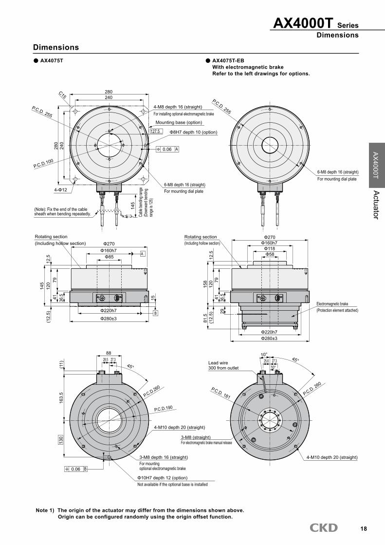
DimensionsAX4075T AX4075T-EB
With electromagnetic brakeRefer to the left drawings for options.
10°
P.C.D. 181
P.C.D. 255
Rotating section (Including hollow section)
Φ280±3 (12.
5)
Φ270 Φ160h7
Φ220h7
36.5
12.5
12
0
4-M10 depth 20 (straight)
6-M8 depth 16 (straight) For mounting dial plate
P.C.D. 255
Rotating section (Including hollow section)
Φ280±3
(12.
5)
Φ270 Φ160h7
Φ220h7
36.5
Lead wire 300 from outlet
12.5
12
0
3-M8 (straight) For electromagnetic brake manual release
4-M10 depth 20 (straight)
P.C.D. 260
Φ118 Φ58
158
Electromagnetic brake (Protection element attached) 29
81.5
6-M8 depth 16 (straight) For mounting dial plate
240
280
240 280
P.C.D.100
Φ8H7 depth 10 (option)
Φ85
C15
4-Φ12
Mounting base (option)
145
P.C.D.260
Φ10H7 depth 12 (option) Not available if the optional base is installed
3-M8 depth 16 (straight)
optional electromagnetic brakeFor mounting
45°
88
15
P.C.D.190
79
79
4-M8 depth 16 (straight) For installing optional electromagnetic brake
41
41
45°
10°
163.
5 (1
1)
0.06 A
127.5
A
B
130
0.06 B
Cable
bend
ing ra
nge
(Dow
nward
bend
ingran
ge is
125)
145
(Note): Fix the end of the cable sheath when bending repeatedly.
27.3 26.5 27.3 25.6
Note 1) The origin of the actuator may differ from the dimensions shown above. Origin can be configured randomly using the origin offset function.

19
Actuator specifications
Direct drive actuator
AX4000T SeriesCapable of handling large moment inertiaWide variety of optionsEasier to pipe and wire with large inner diameter
Max. torque: 150/300/500N•mCompatible drier: TH type driver
Descriptions AX4150T AX4�00T AX4500T
Maximum output torque N•m 150 �00 500Continuous output torque N•m 50 100 160Max. rotation speed rpm 100 (Note 1) 70Allowable axial load N 20000Allowable moment load N•m �00 400 500Output shaft moment of inertia kg/m2 0.2120 0.�260 0.7210Allowable load moment of inertia kg/m2 75.00 (Note 2) 180.00 (Note 2) �00.00 (Note 2)Index accuracy (Note �) sec. ±�0Repeatability (Note �) sec. ±5Output shaft friction torque N•m 10.0 15.0Resolver resolution P/rev 540672Motor isolation class Class FMotor withstanding voltage 1500 VAC for one minuteMotor isolation resistance 10MΩ 500 VDC and overAmbient temperature range 0 to 45°CAmbient humidity range 20 to 85%RH with no dew condensationStorage ambient temperature range -20 to 80°CStorage ambient humidity range 20 to 90%RH with no dew condensationAtmosphere No corrosive gas, flammable or powder dustWeight kg 44.0 66.0 115.0Total weight with brake kg 6�.0 86.0 -Run out of output shaft mm 0.0�Run out of output shaft surface mm 0.05Protection IP20Note1: The speed must be kept below 80rpm during continuous rotation.Note2: The default setting will be large inertia moment compatibleNote�: Refer to "Technical explanations" on page 49 for the details on index accuracy and repeatability.Note4: The max. ambient temperature is 40 °C if used as an UL certified product.
Electromagnetic brake specifications (option)
Read the precautions on Intro 9 to 1� during use.
Compatible modelsDescriptions AX4150T/AX4�00T
Type Non-backlash dry non-excitation operation typeRated voltage V DC24VPower supply wattage W 55Rated current A 2.�0Static friction torque N•m 200Armature release time (brake on) msec 50 (reference value)Armature suction time (brake off) msec 250 (reference value)Holding precision Minute 45 (reference value)Max. cycle rate Time/min. 40Note 1: When the output shaft is rotating, rubbing noise may be generated at the electromagnetic brake's disk and fixing section.Note 2: When moving after brakes are turned OFF, the delay time parameter must be changed based on armature suction time.Note �: This is a nonbacklash type, but it may be hard to hold a set position if load is applied in the direction of rotation.Note 4: When electromagnetic brakes function, the armature may contact the magnetic brake's fixed section and generate noise.Note 5: Brakes are manually released by alternately screwing screws into manual release taps (� positions). Lightly tighten
screws until they stop, then turn them another 90°. When finished with manual release, remove the three bolts immediately and apply brakes.

20
How to orderAX4000T Series
AX
4000TA
ctuator
H Interface specifications
How to order
F Dowel hole Note 4, Note 6
E Brake Note 5
G Body surface treatment Note �
B Driver type
Model no.
A Size (max. torque)
D Cable length Note 2
Note on model no. selectionNote 1: Use the table below to select the appropriate driver.
Driver-power voltage tableDriver
TypeModel
TH type driverThree phase
200 2�0 to VACAX4150T BlankAX4�00T BlankAX4500T Blank
Model Model no. of options
AX4 300 DM04 EBBSTH P1 S U0
Symbol Descriptions
A Size (max. torque)150 150N•m�00 �00N•m500 500N•m
B Driver typeTH TH type driver
C Mounting base (can not be used with a dowel hole P2, P�)Blank Standard (without mounting base)
B With blackened mounting base
BS Electroless nickel plating, surface treatment mounting base Use with body surface treatment S.
F Dowel holeBlank Standard (without dowel hole)
P1 1 on topP2 1 on bottomP� 1 each on both top and bottom
G Body surface treatment
Blank Standard (Rotating section-blackening fixed section outside circumference-paint)
S Rotating section: electroless nickel plating, fixed section: nitrating
E BrakeBlank Standard (without electromagnetic brake)
EB With negative actuation type electromagnetic brake
Note 2: The cable is a flexible cable.Refer to page �5 for dimensions of a cable.
Note �: Select surface treatment and mounting base surface treatment with C
and G . By selecting the optional electroless nickel plating treatment, you can expect higher rust resistance compared to standard specifications.
Note 4: "P2" and "P�" cannot be selected if "B" with blackened mounting base or "BS" electroless nickel plating surface treatment mounting base is selected for C Mounting base.
Note 5: Refer to the Option Table below and select required options.Option table
AX4150T AX4�00T AX4500TElectromagnetic brake (-EB)
'Note 6: Additionally machined sections such as dowel holes may not have a treated surface.
Set model no.(actuator, driver, cable)
*Custom orders are not CE, UL/cUL, RoHS certified. Consult with CKD for details.
Discrete actuator body model no. Discrete driver model no.AX4 T SP1B AX9000TH U0
Three phase 200 to 2�0 VAC
A Size
C Mounting base
G Body surface treatment
F Dowel hole
E Brake
( )D Cable changeNote: "04" for cable
length 4 m
Discrete cable model no.
AX CBLR6 DM04
Motor cable
Resolver cable
AX CBLM6 DM04
D Cable lengthDM02 2mDM04 4m (standard length)DM06 6mDM08 8mDM10 10mDM15 15mDM20 20m
H Interface specifications
H Interface specificationsU0 Parallel I/O (NPN specifications)U1 Parallel I/O (PNP specifications)(Coming soon)U2 CC-LinkU� PROFIBUS-DPU4 DeviceNet (available soon)
C Mounting base Note �, Note 4

21
AX4000T Series
Speed/max. torque characteristics
F
F
L
(Note) moment load
M(N•m)=F(N)×L(m)M: Moment loadF: LoadL: Distance from output shaft center
M(N•m)=F(N)×(L+0.02)(m)M: Moment loadF: LoadL: Distance from output shaft flange
(Fig. a) (Fig. b)
L
AX4150TH AX4�00TH
AX4500TH
*This graph shows the characteristics under 3 phase AC200V
Continuousmovementrange
*This graph shows the characteristics under 3 phase AC200V
Continuousmovementrange
*This graph shows the characteristics under 3 phase AC200V
Continuousmovementrange

22
DimensionsAX4000T Series
AX
4000TA
ctuator
DimensionsAX4150T AX4150T-EB
With electromagnetic brakeRefer to the left drawings for options.
0.06 A
0.06 B
A
B
P.C.D.255
Rotating section (Including hollow section)
Φ280±3 (12.
5)
Φ270 Φ160h7
Φ220h7
36.5
12.5
4-M10 depth 20 (straight)
6-M8 depth 16 (straight) For mounting dial plate
P.C.D.255
Rotating section (Including hollow section)
Φ280±3
(12.
5)
Φ270 Φ160h7
Φ220h7
36.5
Lead wire 300 from outlet
3-M8 (straight) For electromagnetic brake manual release
4-M10 depth 20 (straight)
P.C.D.260
Φ118 Φ58
Electromagnetic brake (Protection element attached) 29
81.5
6-M8 depth 16 (straight) For mounting dial plate
240
280
240 280
P.C.D.100
Φ8H7 depth 10 (option) 127.5
Φ85
C15
4-Φ12
Mounting base (option)
P.C.D.260
130
Φ10H7 depth 12 (option) Not available when using optional mounting base
3-M8 depth 16 (straight)
optional electromagnetic brakeFor mounting
15
P.C.D.190
4-M8 depth 16 (straight) For installing optional electromagnetic brake
41
41
104
145
104
145
12.5
18
3
47.5
168
6.5 116
26
(11)
170
145
Cable
ben
ding
rang
e (D
ownw
ard
bend
ing
rang
e is
125)
45°
45°
(Note): Fix the end of the cable sheath when bending repeatedly.
P.C.D.181
Note 1) The origin of the actuator may differ from the dimensions shown above. Origin can be configured randomly using the origin offset function.

2�
AX4000T Series
DimensionsAX4�00T AX4�00T-EB
With electromagnetic brakeRefer to the left drawings for options.
0.06 A
0.06 B
A
B
(15.
5)
36.5
231
200
Φ220h7 2-M4 GND for mounting
Φ160h7
Φ85
Φ272
15.5
Φ288±3
Rotating section (Including hollow section)
P.C.D.265
6-M12 depth 24 (straight)
130
Φ10H7 depth 12 (Option)
6-M10 depth 20 (straight) For mounting dial plate
295
P.C.D.255
250
4-Φ14
Mounting base (Option)
C15
295
250
Φ10H7 depth 12 (option) Not available if the optional base is installed.
20
P.C.D.100
4-M8 depth 16 (straight) For installing optional electromagnetic brake
3-M8 depth 16 (straight) For installing optional electromagnetic brake
159
41
116
(15.
5)
36.5
200
Φ220h7
Φ160h7 Φ272
Φ288±3
Rotating section (Including hollow section)
P.C.D.265
6-M12 depth 24 (straight)
6-M10 depth 20 (straight) For mounting dial plate
P.C.D.255
41
159
Φ118 Φ58
29
81.5
26 6.5
47.5
(11)
16
8
145
Cable
bend
ing ra
nge
(Dow
nwar
d ben
ding
rang
e is 1
25).
Lead wire 300 from outlet
10°
244
15.5
30°
30° 45°
127.5
P.C.D.190
3-M8 (straight) For electromagnetic brake manual release
(Note): Fix the end of the cable sheath when bending repeatedly.
2-M4 GND for mounting
Electromagnetic brake(Protection element attached)
10°
P.C.D.181
Note 1) The origin of the actuator may differ from the dimensions shown above. Origin can be configured randomly using the origin offset function.

24
DimensionsAX4000T Series
AX
4000TA
ctuator
DimensionsAX4500T
0.06 A
0.06 B
A
BΦ300±3
P.C.D.255
15.5
Φ282Φ160h7
335
(15.
5)
P.C.D. 265
Φ10H7 depth 12(Option)
Φ85
Φ220h7
2-M4GND for mounting
6-M12 depth 24 (straight)
366
36.5 Fixed section
Rotating section (including hollow section)
6-M10 depth 20 (straight)For mounting dial plate
127.5
250
250
Mounting base(Option)
295
C15
295
4-Φ14
2013
0
Φ10H7 depth 12 (option)Not available if the optional base is installed.
4129
4
6.5116
26
(11)
30°
174
47.5
145
Cable
bend
ing ra
nge
(Dow
nwar
d ben
ding
rang
e is 1
25).
(Note): Fix the end of the cable sheath when bending repeatedly.
Note 1) The origin of the actuator may differ from the dimensions shown above. Origin can be configured randomly using the origin offset function.

25
Actuator specificationsDescriptions AX410WTMaximum output torque N•m 1000Continuous output torque N•m ��0Max. rotation speed rpm �0Allowable axial load N 20000Allowable moment load N•m 400Output shaft moment of inertia kg/m2 2.72Allowable load moment of inertia kg/m2 600.00Index accuracy (Note 1) sec. ±�0Repeatability (Note 1) sec. ±5Output shaft friction torque N•m 20.0Resolver resolution P/rev 540672Motor isolation class Class FMotor withstanding voltage 1500 VAC for one minuteMotor isolation resistance 10MΩ 500 VDC and overAmbient temperature range 0 to 45°CAmbient humidity range 20 to 85%RH with no dew condensationStorage ambient temperature range -20 to 80°CStorage ambient humidity range 20 to 90%RH with no dew condensationAtmosphere No corrosive gas, flammable or powder dustWeight kg 198Run out of output shaft mm 0.0�Run out of output shaft surface mm 0.08Protection IP20
Note1: Refer to "Technical explanations" on page 49 for the details on index accuracy and repeatability.Note2: The max. ambient temperature is 40°C if used as an UL certified product.
Speed/max. torque characteristics
F
F
L
M(N•m)=F(N)×L(m)M: Moment loadF: LoadL: Distance from output shaft center
M(N•m)=F(N)×(L+0.02)(m)M: Moment loadF: LoadL: Distance from output shaft flange
(Fig. a) (Fig. b)
L
It may take a few seconds to stop depending on the speed and load conditions, even with emergency stop.
(Note) moment load
WARNING
Safety precautions
Large direct drive actuator
AX400WT SeriesMax. torque 1000N•mlarge hollow shaft handy for cable wiring and piping, and a variety of options
Max. torque: 1000N•mCompatible drier: TH type driver
AX410WTH
*This graph shows the characteristics under 3 phase AC200V
Continuousmovementrange

26
How to orderAX400WT Series
AX
4000TA
ctuator
G Interface specifications
Set model no.(actuator, driver, cable)
*Custom orders are not CE, UL/cUL, RoHS certified. Consult with CKD for details.
Discrete actuator body model no. Discrete driver model no.AX410WT SP1B AX9000TH U0
Three phase 200 to 2�0 VAC
C Mounting base
F Body surface treatment
E Dowel hole
How to order
Note on model no. selection
D Cable length Note 1
C Mounting base Note 2, Note �
Model no.
AX4 10W DM04BSTH P1 U0S
Model Model no. of options
Symbol DescriptionsA Size (max. torque)
10W 1000N•m
B Driver typeTH TH type driver
C Mounting base (can not be used with a dowel hole P2, P�.)Blank Standard (without mounting base)
B With blackened mounting base
BS Electroless nickel plating surface treatment mounting baseUse with body surface treatment S.
E Dowel holeBlank Standard (without dowel hole)
P1 1 on top
P2 1 on bottom
P� 1 each on both top and bottom
F Body surface treatmentBlank Standard (Rotating section-blackening fixed section outside circumference-paint)
S Rotating section: electroless nickel plating, fixed section: nitrating
A Size (max. torque)
B Driver type
F Body surface treatment Note 2
Note 1: The cable is a flexible cable. Refer to page �5 for dimensions of a cable.
Note 2: Select surface treatment and mounting base surface treatment with C and E . By selecting the optional electroless nickel plating treatment, you can expect higher rust resistance compared to standard specifications.
Note �: "P2" and "P�" cannot be selected if "B" with blackened mounting base or "BS" electroless nickel plating surface treatment mounting base is designated for C Mounting base.
Note 4: The dowel hole section may not have a surface treatment.
E Dowel hole Note �, Note 4
( )
Discrete cable model no.
AX CBLM6 DM04
D Cable changeNote: "04" for cable
length 4 m
Motor cable
Resolver cableAX CBLR6 DM04
D Cable lengthDM02 2mDM04 4m (standard length)DM06 6mDM08 8mDM10 10mDM15 15mDM20 20m
G Interface specifications
G Interface specificationsU0 Parallel I/O (NPN specifications)U1 Parallel I/O (PNP specifications)(Coming soon)U2 CC-LinkU� PROFIBUS-DPU4 DeviceNet

27
AX400WT Series
DimensionsAX410WT
(Lifting)
(Down
ward
bend
ingran
ge is
125).
Not possible when using optional mounting base
4-Φ18
4-M12 (discrete mounting base lifting)
For mounting dial plate8-M10 depth 20 (straight)
Mounting base (option)
440380
PCD3
90Φ10H7 depth 12 (option)
11.2
5°A0.06
M12 depth 24 05 4- (straight)
195
A
Φ420Φ160h7
Φ85 (hollow)
Cable b
ending
range
145
Fixed section
25
B
(11)
243
Φ350h7
2-M4GND for mounting
Φ435±4
6.526
30°
116
200
6-M12 depth 25 (straight)Platform for mountingP.C.D.400
Φ10H7 depth 12 (option)B
47.5
(20)
(Note): Fix the end of the cable sheath when bending repeatedly.
(Including hollow section)Rotating section
320
380
440
275
240
15
36.544
0.06
PCD 101
C15
Note 1) The origin of the actuator may differ from the dimensions shown above. Origin can be configured randomly using the origin offset function.

28

29
Direct drive actuator
TS·TH type driver
Common specificationsDescriptions
ModelTS type driver
AX9000TSTH type driver
AX9000TH
Power voltage
Main power supply
Three phase 200V±10% to AC2�0 VAC ±10% (Note 1)Single phase 200V±10% to AC2�0 VAC ±10% (Option J1) (Note2, �)
Control power supply
Single phase 200V±10% to AC2�0 VAC ±10%Single phase 200V±10% to AC2�0 VAC ±10% (Option J1) (Note2, �)
Power supply frequency 50/60 Hz
Rated input current AC200V: 1.8A AC100V: 2.4A AC200V: 5.0A
Rated output current 1.9A 5.0AStructure Driver and controller integrated type (open frame)Ambient temperature range 0 to 50°CAmbient humidity range 20 to 90%RH (with no dew condensation)Storage ambient temperature range -20 to 80°CStorage ambient humidity range 20 to 90%RH (with no dew condensation)Atmosphere With no corrosive gas and powder dust
Noise-resistance 1000V(P-P), pulse amplitude 1μsec, start up 1nsecEMI test inductive noise (capacity coupling)
Vibration resistance 4.9m/s2
Weight 1.6k g 2.1k gProtection IP2X(excluding CN4,CN5)
Note 1: Single phase 200 to 2�0 VAC is available for models with a torque of 45N•m or less.Note 2: Connecting 200 to 2�0 VAC to 100 to 115VAC specifications
(option -J1) will destroy the driver.Note �: (-J1) cannot be selected for models with a max. torque of 75N•m or more.Note 4: If the power has been cut off while the actuator is rotating, the
rotation may continue due to inertia.Note 5: In some cases, the motor will move due to the remaining
Descriptions DescriptionsNumber of control axis 1 shaft and 540672 pulse/1 rotationAngle input increment ° (degree), pulse, index numberMin. angle setting unit 0.001° and 1 pulseSpeed input increment seconds, rpmSpeed setting range 0.01 to 100 second/0.01 to �00rpm (Note 1)Equal index number 1 to 255Maximum command value 7-digits input ±9999999Timer 0.01 to 99.99 sec.Programming language NC languageProgramming method Data can be set with an Teaching Pendant or personal computer, etc., using the RS-2�2-C port.Operation mode Automatic, MDI, jog, single block, servo OFF, pulse string input modeCoordinates Absolute, incremental
Acceleration curve<5 type>
Modified sine(MS) , modified constant velocity(MC ・MC2) , modified trapezoidal(MT) , Trapecloid(TR)
Status display LED power displayOperating indication 7-segments LED display (2 digit)Communication interface RS-2�2C compliantI/O signal Refer to page of each interface specifications.Program capacity Approx. 6000 character (256 programs)Electronic thermal Overheat protection of actuator
Note 1) max. rotation speed differs depending on the actuator to be connected.
Power supply wattage and breaker capacityTS type driver
Actuator model no. Driver model no.Power supply wattage (KVA) Rush current (A) Breaker capacity
Max. Rated Single phase 100V Single phase and three phase 200V Rated current (A)AX2006T
AX9000TS
0.8 0.5
16(Note1)56(Note1) 10
AX4009T,AX2012T,AX2018T, AX4009T,AX4022T 1.0 0.5
AX1045T,AX4045T 1.5 0.5AX1075T,AX4075T 2.0 0.8 ―
TH type driver
Actuator model no. Driver model no.Power supply wattage (KVA) Rated input current (A) Driver
output (A) Rush current (A) Breaker capacity
Max. Rated Three phase 200V Max. Three phase 200V Rated current (A)AX4150T and AX1150T
AX9000TH
�.0 0.8 4.2 16.7
50 20AX4�00T and AX1210T 4.0 1.5 6.1 25.0AX4500T 4.0 2.0 6.1 25.0AX410WT 4.0 2.0 6.1 25.0
Interface specifications: Parallel I/O (NPN specifications) Parallel I/O (PNP specifications)(Coming soon) CC-Link PROFIBUS-DP DeviceNet
FeaturesSeparated main and control power supplyWiring methods changed from terminal block to connectorCompact and light weight (resin body)7 segment 2-digit LED displayEncoder output added (only for parallel I/O)Optional serial communication (circuit board integrated)Add a monitor for positioning information and alarm condition. (Only U2,U�,U4 option)
AX9000TS U0AX9000TH U0
Interface specificationsU0: Parallel I/O (NPN) U1:Parallel I/O (PNP)(Coming soon)U2:CC-LinkU�:PROFIBUS-DPU4: DeviceNet
Three phase 200 to 2�0 VAC
Single phase 100 to 115 VACAX9000TS J1 U0
How to order
Performance specifications
electricity in the drive, even after the power has been cut off.
Note 1)Rush current value is typical value in AC115V and AC2�0V.
Note 1)Rush current value is typical value in AC2�0V.

�0
TS·TH type driverA
X9000TS
AX
9000THD
river
CN� I/O circuit specifications
I/O circuit specificationsDescriptions
1 circuit current
(mA)
Max. point
(Circuit)
Max. current
(mA)
Max. current consumption
(mA)Input circuit 4 14 56
1106Output circuit 50 18 900Brake output (BK +, BK-) 75 2 150
*The output circuit can only output 14 points out of 18 points simultaneously.
CN� output signalPin No. Signal name Logic
�� M code output (bit 0) Positive�4 M code output (bit 1) Positive�5 M code output (bit 2) Positive�6 M code output (bit �) Positive�7 M code output (bit 4) Positive�8 M code output (bit 5) Positive�9 M code output (bit 6) Positive40 M code output (bit 7) Positive41 Inposition input Positive42 Positioning complete output Positive4� Start input waiting output Positive44 Alarm output 1 Negative45 Alarm output 2 Negative46 Output during indexing 1/origin position output Positive47 Output during indexing 2/servo state output Positive48 Ready output Positive49 Output Positive50 M code strobe output Positive
CN� input signalPin No. Signal name Logic Judgment
1 to 2 External power input + 24V±10%� to 4 External power input GND
5 Program no. selection input (bit 0) Positive Level6 Program no. selection input (bit 1) Positive Level7 Program no. selection input (bit 2) Positive Level8 Program no. selection input (bit �) Positive Level
9 Program no. setting input 2nd digit/program no. selection input (bit 4) Positive Edge
Level
10 Program no. setting input 1st digit/program no. selection input (bit 5) Positive Edge
Level11 Reset input Positive Edge12 Return to origin command input Positive Edge1� Start input Positive Edge
14 Servo on input/program stop input Positive Level
Edge15 Ready return/continuous rotation stop input Positive Edge16 Answer input/position deviation count reset input Positive Edge17 Emergency stop input Negative Level18 Brake release input Positive Level
CN� pulse string input signalPin No. Signal name
19 PULSE/UP/A phase20 -PULSE/-UP/-A phase21 DIR/DOWN/B phase22 -DIR/-DOWN/-B phase
CN� encoder output signal (incremental)Pin No. Signal name
2� A phase (line driver output)24 -A phase (line driver output)25 B phase (line driver output)26 -B phase (line driver output)27 Z phase (line driver output)28 -Z phase (line driver output)
Input circuit
Output circuit+ 24V±10%
33 to 50 pin
Load
3, 4 pin
5 to 18 pin + 24V±10%
1.2 pin
19, 21 pin
20, 22 pin
Rated voltage 5V±10%Max. input frequencyLine driver 1MppsOpen collector 250Kpps
240Ω
510Ω
Rated voltage 24V±10%Rated current 50mA (Max.)
Rated voltage 24V±10%Rated current 4mA (at DC24 V)
Pulse string input circuit
23, 25, 27 pin
24, 26, 28 pin
Output type: line driverUse line driver: DS26C31Recommended line receiver: DS26C32 equivalent
Encoder output circuit
1.2 pin
Parallel I/O (NPN specifications)Specifications
*Custom orders are not CE, UL/cUL, RoHS certified.

�1
TS·TH type driver
CN� I/O circuit specifications
I/O circuit specificationsDescriptions
1 circuit current
(mA)
Max. point
(Circuit)
Max. current
(mA)
Max. current consumption
(mA)Input circuit 4 14 56
1106Output circuit 50 18 900Brake output (BK +, BK-) 75 2 150
*The output circuit can only output 14 points out of 18 points simultaneously.
CN� output signalPin No. Signal name Logic
�� M code output (bit 0) Positive�4 M code output (bit 1) Positive�5 M code output (bit 2) Positive�6 M code output (bit �) Positive�7 M code output (bit 4) Positive�8 M code output (bit 5) Positive�9 M code output (bit 6) Positive40 M code output (bit 7) Positive41 Inposition input Positive42 Positioning complete output Positive4� Start input waiting output Positive44 Alarm output 1 Negative45 Alarm output 2 Negative46 Output during indexing 1/origin position output Positive47 Output during indexing 2/servo state output Positive48 Ready output Positive49 Output Positive50 M code strobe output Positive
CN� input signalPin No. Signal name Logic Judgment
1 to 2 External power input GND(Note 1)� to 4 External power input + 24V±10%(Note 1)
5 Program no. selection input (bit 0) Positive Level6 Program no. selection input (bit 1) Positive Level7 Program no. selection input (bit 2) Positive Level8 Program no. selection input (bit �) Positive Level
9 Program no. setting input 2nd digit/program no. selection input (bit 4) Positive Edge
Level
10 Program no. setting input 1st digit/program no. selection input (bit 5) Positive Edge
Level11 Reset input Positive Edge12 Return to origin command input Positive Edge1� Start input Positive Edge
14 Servo on input/program stop input Positive Level
Edge15 Ready return/continuous rotation stop input Positive Edge16 Answer input/position deviation count reset input Positive Edge17 Emergency stop input Negative Level18 Brake release input Positive Level
CN� pulse string input signalPin No. Signal name
19 PULSE/UP/A phase20 -PULSE/-UP/-A phase21 DIR/DOWN/B phase22 -DIR/-DOWN/-B phase
CN� encoder output signal (incremental)Pin No. Signal name
2� A phase (line driver output)24 -A phase (line driver output)25 B phase (line driver output)26 -B phase (line driver output)27 Z phase (line driver output)28 -Z phase (line driver output)
Input circuit
Output circuit+ 24V±10%
33 to 50 pin
Load
3, 4 pin
5 to 18 pin + 24V±10%
1.2 pin
19, 21 pin
20, 22 pin
Rated voltage 5V±10%Max. input frequencyLine driver 1MppsOpen collector 250Kpps
240Ω
510Ω
Rated voltage 24V±10%Rated current 50mA (Max.)
Rated voltage 24V±10%Rated current 4mA (at DC24 V)
Pulse string input circuit
23, 25, 27 pin
24, 26, 28 pin
Output type: line driverUse line driver: DS26C31Recommended line receiver: DS26C32 equivalent
Encoder output circuit
1.2 pin
Parallel I/O (PNP specifications)(coming soon)
*Custom orders are not CE, UL/cUL, RoHS certified.
Note 1) Wire differs from PNP specifications of AX9000GS/GH.

�2
TS·TH type driverA
X9000TS
AX
9000THD
river
I/O signalDevice
No. Signal name Logic Judgment
RYn0 Program no. selection input (bit 0) Positive Level
RYn1 Program no. selection input (bit 1) Positive Level
RYn2 Program no. selection input (bit 2) Positive Level
RYn� Program no. selection input (bit �) Positive Level
RYn4 Program no. setting input the second digit/program no. selection input (bit 4) Positive Edge
level
RYn5 Program no. setting input the first digit/program no. selection input (bit 5) Positive Edge
level
RYn6 Reset input Positive Edge
RYn7 Return to origin command input Positive Edge
RYn8 Start input Positive Edge
RYn9 Servo on input/program stop input Positive Level
edge
RYnA Ready return input/continuous rotation stop input Positive Edge
RYnB Answer input/position deviation count reset Positive Edge
RYnC Emergency stop input Negative Level
RYnD Brake release input Positive Level
RYnE Not available
RYnF Not available
RY(n+1)0to
RY(n+1)FNot available
RY(n+2)0 Monitor output action request Positive Edge
RY(n+2)1 Command execution request Positive Edge
RY(n+2)2to
RY(n+2)FNot available
"n" is a value that depends on the station no. setting
Communication specifications
Descriptions SpecificationsPower supply DC5V supplied from servo ampCC-Link version Ver.1.10Occupied station no. (station type) 2 stations (remote device station)Remote input no. 48 pointRemote output no. 48 pointRemote register I/O Input 8 words/ Output 8 words
Communication speed 10M/5M/2.5M/625k/156kbps (select with the parameter setting)
Communication method Broadcast polling methodSynchronization method Frame synchronization methodSymbol method NRZILine type Bus type (EIA RS-485 compliant)Incorrect control method CRC(X16+X12+X6+1)
Connection cable CC-Link Ver.1.10 cable(shielded � wire twisted pair cable)
Transmission format HDLC compliantRemote station no. 1 to 6� (setting by parameter)Connection quantity
At only remote device stationMax.�2 unit/2 station occupied
Monitor functions
Current position (degrees,. pulse), position deviation, program no., electric thermal, rotation speed, alarm
CC-Link specifications
TB� input circuit specifications (emergency stop)
EMG+
External power DC24(not included)
Rated voltage 24V±10%, rated current 5mA or less
*
*External power supplycan be used with the polarity reversed
EMG-
+24V
Maintain sufficient distance between the communication cable and the power and motor cable.Do not bundle communication and power cable as it may cause communication errors and failures due to instability caused by noise.Refer to materials such as CC-Link laying manual for details on laying the cables.
Safety precautions
DeviceNo. Signal name Logic
RXn0 M code output (bit 0) Positive
RXn1 M code output (bit 1) Positive
RXn2 M code output (bit 2) Positive
RXn� M code output (bit �) Positive
RXn4 M code output (bit 4) Positive
RXn5 M code output (bit 5) Positive
RXn6 M code output (bit 6) Positive
RXn7 M code output (bit 7) Positive
RXn8 Inposition input Positive
RXn9 Positioning complete output Positive
RXnA Start input waiting output Positive
RXnB Alarm output 1 Negative
RXnC Alarm output 2 Negative
RXnD Output during indexing 1/origin position output Positive
RXnE Output during indexing 2/servo state output Positive
RXnF Ready output Positive
RX(n+1)0 Output Positive
RX(n+1)1 M code strobe output Positive
RX(n+1)2to
RX(n+1)FNot available
RX(n+2)0 Monitor medium Positive
RX(n+2)1 Command completion Positive
RX(n+2)2to
RX(n+2)FNot available
CC-Link Specifications
PLC→AX(Input) AX→PLC(Output)

��
TS·TH type driver
TB� input circuit specifications (emergency stop)
EMG+
External power DC24(not included)
Rated voltage 24V±10%, rated current 5mA or less
*
*External power supplycan be used with the polarity reversed
EMG-
+24V
Maintain sufficient distance between the communication cable and the power and motor cable.Do not bundle communication and power cable as it may cause communication errors and failures due to instability caused by noise.Refer to materials such as DeviceNet laying manual for details on laying the cables.
Safety precautions
I/O signalByteNo. Signal name Logic Judgment
0.0 Program no. selection input (bit 0) Positive Level
0.1 Program no. selection input (bit 1) Positive Level
0.2 Program no. selection input (bit 2) Positive Level
0.� Program no. selection input (bit �) Positive Level
0.4 Program no. selection input (bit 4)/program no. setting input the second digit Positive Level
edge
0.5 Program no. setting input the first digit/program no. selection input (bit 5) Positive Level
edge
0.6 Reset input Positive Edge
0.7 Return to origin command input Positive Edge
1.0 Start input Positive Edge
1.1 Servo on input/program stop input Positive Level
edge
1.2 Ready return input/continuous rotation stop input Positive Edge
1.� Answer input/position deviation count reset Positive Edge
1.4 Emergency stop input Negative Level
1.5 Brake release input Positive Level
1.6 Not available
1.7 Not available
2.0to2.5
Not available
2.6 Monitor output action request Positive Level
2.7 Command execution request Positive Edge
Communication specificationsDescriptions Specifications
Power supply for communication 11 to 25 VDC
Current consumption of power supply for communication
50mA or less
Communication protocol DeviceNet compliant: remote I/O
Occupying nodes Input 8 byte/output 8 byte
Communication speed 500k/250k/125kbps(Select with the parameter setting.)
Connection cableDeviceNet compatible cable(Shielded 5 wire cable,2 signal lines, 2 power lines, 1 shield)
Node address 0 to 6� (set with parameter)Connection quantity Max.64 unit (including master)
DeviceNet specifications (available soon)
ByteNo. Signal name Logic
0.0 M code output (bit 0) Positive
0.1 M code output (bit 1) Positive
0.2 M code output (bit 2) Positive
0.� M code output (bit �) Positive
0.4 M code output (bit 4) Positive
0.5 M code output (bit 5) Positive
0.6 M code output (bit 6) Positive
0.7 M code output (bit 7) Positive
1.0 Inposition input Positive
1.1 Positioning complete output Positive
1.2 Start input waiting output Positive
1.� Alarm output 1 Negative
1.4 Alarm output 2 Negative
1.5 Output during indexing 1/origin position output Positive
1.6 Output during indexing 2/servo state output Positive
1.7 Ready output Positive
2.0 Output Positive
2.1 M code strobe output Positive
2.2to2.5
Not available
2.6 Monitor medium Positive
2.7 Command completion Positive
PLC→AX(Input) AX→PLC(Output)

�4
TS·TH type driverA
X9000TS
AX
9000THD
river
Description SpecificationsCommunication protocol PROFIBUS DP-V0 compliant
I/O data Input 8 byte/output 8 byte
Communicationspeed
12M/6M/�M/1.5M/500k/187.5k/9�.75k/45.45k/19.2k/9.6kbps(auto baud rate function)
Connectioncable
PROFIBUS cable(shielded 2 wire twisted pair cable)
Node address 0 to 125 (set with parameter)
Connectionquantity
Without repeater:Max. �2 stations for each segmentWith repeaterMax. total of 126 stations
Monitor function
Current position (degrees,. pulse), position deviation, program no., electric thermal, rotation speed, alarm
Communication specifications
EMG+
External power DC24(not included)
Rated voltage 24V±10%, rated current 5mA or less
*
*External power supplycan be used with the polarity reversed
EMG-
+24V
TB� input circuit specifications (emergency stop)
Refer to materials such as “Installation Guideline for PROFIBUS DP/FMS” for details on laying the cables.
I/O signal
ByteNo. Signal name Logic Judgment
0.0 Program no. selection input (bit 0) Positive Level
0.1 Program no. selection input (bit 1) Positive Level
0.2 Program no. selection input (bit 2) Positive Level
0.� Program no. selection input (bit �) Positive Level
0.4 Program no. selection input (bit 4)/program no. setting input the second digit Positive Level
edge
0.5 Program no. setting input the first digit/program no. selection input (bit 5) Positive Level
edge
0.6 Reset input Positive Edge
0.7 Return to origin command input Positive Edge
1.0 Start input Positive Edge
1.1 Servo on input/program stop input Positive Level
edge
1.2 Ready return input/continuous rotation stop input Positive Edge
1.� Answer input/position deviation count reset Positive Edge
1.4 Emergency stop input Negative Level
1.5 Brake release input Positive Level
1.6 Not available
1.7 Not available
2.0to2.5
Not available
2.6 Monitor output action request Positive Level
2.7 Command execution request Positive Edge
ByteNo. Signal name Logic
0.0 M code output (bit 0) Positive
0.1 M code output (bit 1) Positive
0.2 M code output (bit 2) Positive
0.� M code output (bit �) Positive
0.4 M code output (bit 4) Positive
0.5 M code output (bit 5) Positive
0.6 M code output (bit 6) Positive
0.7 M code output (bit 7) Positive
1.0 Inposition input Positive
1.1 Positioning complete output Positive
1.2 Start input waiting output Positive
1.� Alarm output 1 Negative
1.4 Alarm output 2 Negative
1.5 Output during indexing 1/origin position output Positive
1.6 Output during indexing 2/servo state output Positive
1.7 Ready output Positive
2.0 Output Positive
2.1 M code strobe output Positive
2.2to2.5
Not available
2.6 Monitor medium Positive
2.7 Command completion Positive
Safety precautions
PROFIBUS-DP specification
PLC→AX(Input) AX→PLC(Output)

�5
TS·TH type driverDimensions
TS type driver
TH type driver
G2
G1
TMON.
SERIES
CN2
CN4
+ S2+ S1
CN1
ABSODEX DRIVER
CN3
- S2
CN5
TB2
BK +BK -
- S1
TB1
CHARGE
POWER
L1
L3
L2
L2C
50/60Hz-115V
AC100
L1C
U
V
W
CKD Corporation
MODEL: AX9000TH
MADE IN JAPAN
ABSODEX
SERIAL:+25A1+25A1+25A1+25A1+25A1+25A1+25A1
55
95
65±0.5(Mounting pitch)
(5)
210±
0.5
(mou
ntin
g pi
tch)
220
6
(100)160
220
95
Installation hole machining drawing (Note 1)
3-M4 (thread hole)
Driver appearanceRegenerative resistance
75
65±0.5(Mounting pitch)
55(5
)21
0±0.
5 (m
ount
ing
pitc
h)
220
Installation hole machining drawing (Note 1)75(100)160
220
6
3-M4 (thread hole)
Driver appearance
Note : The mounting pitch differs from conventional models (AX9000GS/AX9000GH)

�6
TS·TH type driverA
X9000TS
AX
9000THD
river
C N 1
C N 2
C N 3
T B 1
T B 2
C N 1
C N 2
C N 3
T B 1
T B 2
BK + BK -
CN5
V
W
U
CN4
CHARGE
POWER
T SERIES
MON.
G2
G1
DRIVER
3AC200 -230V
50/60Hz
L1C
L2C
L3
L1
L2
ABSODEX
BK + BK -
CN5
V
W
U
CN4
CHARGE
POWER
T SERIES
MON.
G2
G1
DRIVER
3AC200 -230V
50/60Hz
L1C
L2C
L3
L1
L2
ABSODEX
FootprintTS type driver
TH type driver
Note 1) Provide extra space depending on your cable.
The driver is not dustproof and waterproof.Protect the direct driver to keep out dust,water and oil fumes if there is any in your environment.Keep the temperture of the control box below 50 ℃ and maintain space as shown below, if placed in a control box.
Footprint

�7
TS·TH type driver
PROFIBUS-DP specifications
- BK BK +
CN5
U
W
V
C N 3
T B 1
MON.
CN4
CHARGE
POWER
C N 1
C N 2
G2
G1
SERIES DRIVER ABSODEX
T
L3
-230V 50/60Hz
L2C 3AC200
L1C
L2
L1
MODEL :AX9□□□GS
CKD Corporation SERIAL:□□□□□□□
MADE IN JAPAN
ABSODEX T B 3
T B 2
RUN ERR
Control power supply LED
Main power supply LED
Main power supply
Control power supply
ActuatorOutput terminal
Ground terminal2-M4
Operating indication7 segment LED (2 digit)
Gain 1 dip switch(Convergence time)
CN1 RS-232C connector
Gain 2 dip switch(Load)
CN2 resolver cable connector
Terminal for TB1 safety
Transmission monitor LED
TB2 terminal
Terminal for TB3 emergency stop
Parallel I/O (NPN,NPN specifications)
-J1
G2
G1
TMON.
SERIES
CN2
CN4
+ S2+ S1
CN1
ABSODEX DRIVER
CN3
- S2
CN5
TB2
BK +BK -
- S1
TB1
CHARGE
POWER
L1
L2
L2C
50/60Hz-115V
AC100
L1C
U
V
W
CKD Corporation
MODEL: AX9000TS
MADE IN JAPAN
ABSODEX
SERIAL:+25A1+25A1+25A1+25A1+25A1+25A1+25A1
Operating indication7 segment LED (2 digit)
Control power supply LED
Gain 1 dip switch(Convergence time)
CN1 RS-232C connector
Gain 2 dip switch(Load)
CN2 resolver cable connector
Terminal for TB1 safety
CN3 I/0 connector
TB2 terminal
Main power supply LED
Main power supply
Control power supply
ActuatorOutput terminal
Ground terminal2-M4
Operating indication7 segment LED (2 digit)
Control power supply LED
Gain 1 dip switch(Convergence time)
CN1 RS-232C connector
Gain 2 dip switch(Load)
CN2 resolver cable connector
Terminal for TB1 safety
CN3 I/0 connector
TB2 terminal
Main power supply LED
Main power supply
Control power supply
ActuatorOutput terminal
Ground terminal2-M4
CC-Link specifications
Operating indication7 segment LED (2 digit)
Control power supply LED
Gain 1 dip switch(Convergence time)
CN1 RS-232C connector
Gain 2 dip switch(Load)
CN2 resolver cable connector
Terminal for TB1 safety
Transmission monitor LED
TB2 terminal
CN3 CC-Link connector
Terminal for TB3 emergency stop
Main power supply LED
Main power supply
Control power supply
ActuatorOutput terminal
Ground terminal2-M4
BK +BK -
- S1- S2
+ S1+ S2
TB2
TB3
CN3
TB1
CN2
CN1
MNS
CN5
CN4
MON.T
W
V
U
3AC200-230V
50/60Hz
L2C
L1C
L3
L2
L1
CHARGE G2
G1POWER
SERIES
DRIVERABSODEX
Control power supply LED
Operating indication7 segment LED (2 digit)
Gain 1 dip switch(Convergence time)
Gain 2 dip switch(Load)
CN1 RS-232C connector
CN2 resolver cable connector
TB1 safety terminal
Transmission monitor LED
CN3 DeviceNet connector
Terminal for TB3 emergency stop
TB2 terminal
Main power supply LED
Control power supply
Main power supply
ActuatorOutput terminal
Ground terminal2-M4
200 VAC 100 VAC
DeviceNet specifications
Panel explanation
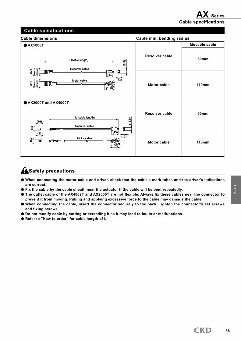
�8
Cable
AX SeriesCable specifications
Safety precautions
When connecting the motor cable and driver, check that the cable's mark tubes and the driver's indications are correct.Fix the cable by the cable sheath near the actuator if the cable will be bent repeatedly.The outlet cable of the AX4009T and AX2000T are not flexible. Always fix these cables near the connector to prevent it from moving. Pulling and applying excessive force to the cable may damage the cable.When connecting the cable, insert the connector securely to the back. Tighten the connector's set screws and fixing screws.Do not modify cable by cutting or extending it as it may lead to faults or malfunctions.Refer to "How to order" for cable length of L.
Cable specifications
AX1000T
Resolver cable
Movable cable
60mm
Motor cable 110mm
AX2000T and AX4000T
Resolver cable 60mm
Motor cable 110mm
UN
Resolver cable
Motor cable
(43)(12)
(18.
5)L (cable length)
(100)
Φ45
(Max
imum
dia
meter
)
Φ21
(Max
imum
dia
meter
)
UN
Resolver cable
Motor cable
(43)(12)
(18.
5)L (cable length)
(100)
Φ45
(Max
imum
dia
meter
)
Φ21
(Max
imum
dia
meter
)
(12)(22)
(15) Motor cable
(100)
L (cable length)(16)
(14) Resolver cable
(43)(1
8.5)
(12)(22)
(15) Motor cable
(100)
L (cable length)(16)
(14) Resolver cable
(43)(1
8.5)
Cable min. bending radiusCable dimensions

�9
Model no.
Direct drive actuator Teaching Pendant
AX0180Common for TS/TH type driver
Features(1) Easy programming
Equal index programs are created easily by answering questions interactively with the dialog terminal.
(2) No dedicated power supply requiredPower is supplied from the teaching pendant.
(�) Back up possiblePrograms and parameters can be stored, and programs can be copied.The conventional model can also be used.
(4) The conventional model can also be used.
SpecificationsDescriptions AX0180Operation mode Edit, display, parameter, operation or copyProgram capacity Equal index or NC program 2000 character (1 program)Program No. Equal index program: program No. 0 to 999Indicator 16 character x 2 line (LCD display)
Input key17key
(Emergency stop key: 1, control key: 5 characters, numerals key: 11)Back up Super capacitor (approx. � hours)Power supply Supply from direct drive actuator driverCable length 2mAmbient temperature range 0 to 50°CAmbient humidity range 20 to 90% (with no dew condensation)Conservation ambient temperature range -20 to 80°C
Conservation ambient humidity range 20 to 90% (with no dew condensation)
Atmosphere With no corrosive gas and powder dustWeight 140g (does not include weight of cable)
DimensionsTeaching Pendant
2486
140
72
Cable length 2m
How to order
AX0180 E
Model Model no. of options
Symbol DescriptionsBlank Standard (Japanese ver.)
E English version

40
Teaching PendantAX0180 Series
AX
0170HTeaching P
endant
Teaching Pendant
Edit mode
Display mode
Parameter Mode
Operation mode
Copy mode
Operation mode
■ Editing program
■ I/O state and current position display
■ Parameter setting
■ One-touch operation command
Equal indexing programs are edited by the teaching pendant and operation programs areedited with NC codes.Only one edited program can be saved. Memory backup: 3hours.After the equal division program is edited, parameters required for operation can be edited.Up to 2000 characters can be input for the NC program.Twelve sample programs that can be edited are included.
The direct drive actuator driver’s input/output signal CN3’s input/output status, the current motor position, and the alarm status, etc., are displayed.
The parameters of direct drive actuator are referenced and set.*The area code and baud rate are able to set up in the serial communication of
Programs are started and stopped, executed one block at a time, reset, numbers set, MDI data input and executed, communications in a terminal mode,brakes turned ON and OFF, servo turned ON and OFF, return to origin executed, JOG operation and offset set, etc.
■ Batch copying of programs All programs stored in the direct drive actuator driver are stored in another driver.
■ Adjustment of the direct drive actuator(The function only for AX9000TS) The gain adjusted using auto tuning function of the direct drive.Tuning mode
Interactive programming Examples of use
Programs are created easily by inputting the following settings:
[Example of program input]Create program Program No. (0 to 999)Return to origin position
1. Origin2. Index
Return direction
1. CW2. CCW
Return speed (1.0 to 20.0) rpmIndex number (1 to 255)Moving time [0.01 to 100] secondRotational direction
1. CW2. CCW
Stop process 1. Start waiting2. Dwell
Brake 1. Used2. Vacant
Delay timer [0.01 to 99.99] secondM code 1. M code
2. Index position
Try operating the direct drive actuator.
Edit mode
Twelve types of sample programs are selectable, so try these during adjustment.
Create a program and store it in the direct drive actuator.
Edit mode
Programs are input and stored in easy steps.
Start a program stored in the direct drive actuator.
Operation mode
Programs are started easily by designating the program number.
Use features of each cam curves.
Parameter mode
Five types of cam curves are selectable. Drives that use features of each type are realized in one-touch operation.
Confirm a I/O on/off. Display mode
The condition of I/O can display.

AX Series
41
Direct drive actuator related parts model no. table
Related partsPart name Model Model no.
PC communication cable (DOS/V) AX Series AX-RS2�2C-9P(Note) This cable is not compact with C type drivers and old models (black drivers). Consult our sales representative when
using for these drivers.
Mounting basePart name Model Model no.
Mounting base AX Series (Note 1) AX-AX****-BASE-* (Note 2)(Note 1) Mounting base is not compatible with AX4009T. (Note 2) Consult our sales representative for the model number of the mounting base.
Noise filterPart name Model Model no.
Noise filter for power supply (three phase 10A) AX Series AX-NSF-�SUP-EF10-ER-6Noise filter for power supply (single phase 15A) AX Series AX-NSF-NF2015A-ODSurge protector AX Series AX-NSF-RAV-781BXZ-4Ferrite core for motor cable AX Series AX-NSF-RC5060
(Note 2)The parts below and over current/short circuit protection components are required to comply with the CE marking. Also, the driver must be placed withing the switch board. Refer to the manual or technical documents for Absodex AX Series TS/TH type to find out how to install them.
(Note 1)Parts of this page are lists of the parts which you can buy.

42
6 5 4
3 2 1
Reference station
Example of index accuracy measurement
Index accuracy ±16
0+ 5”-10”-27”-18” -7”
1 2 3 4 5 6
Measuring Measuring position
+ 5”
-10”-27” -18”
-7”
The indexing accuracy of the Absodex is the gap between the target position set by the NC program and the actual position.This target posit ion is the angle (sec.) from the standard station (return to origin position)As shown to the right, the accuracy is calculated from the target position and the remainder of the actual result with the smallest and largest value.A high precision encoder is used to measure the angle.
Repeat accuracy is the maximum dispersion expressed in angle (sec.) when stopping repeatedly on the specified target position under the same condition. The required accuracy may be repeat or indexing depending on the characteristics of the machine.
Explanation of technical term
Index precision
Repeatability
*Seconds (sec.)= Unit that expresses angle by degrees, minutes and seconds. 1degrees=60minutes=�600seconds
AX SeriesTechnical Explanations

AX Series
4�
Applications (1)
Movement specifications 1 (operation of index unit)
Movement specifications4 index (equal index of 90°)Moving time 0.5 secondIndex once counter clockwise every time there is a start signal from the PLC.
90°Move in 0.5 seconds
Example of program
Main program
O1;
G11;
G10\1A4;
G91.1;
A0\F0\.5;
N1M0\;
A-1F0\.5;
J1;
M30\;
Use program No. “1”
Set the time (sec.) in the NC code F unit.
Split one rotation into 4.
Set the incremental dimensions.
Move to the closest index station in 0.5 sec.
Waiting for start signal from PLC.
Move one index in 0.5 sec.
Jump to the sequence No. 1 block.
Program end
(Note) When using the Teaching note, 1will be automatically configured by entering program no. 1.
Example of PLC operation signalInitial process: process done only once in the beginning
Process name
(1) Program no. selection No. selection 0 bit No. selection 1 bit No. selection 2 bit No. selection 3 bit No. setting the first digit
Start signal Positioning complete signal Start input waiting output
(2) Return process
I/O signal name PLC output PLC input Remarks
Indexing process: process done each time when indexing
(Note) Program selection and start signal input must be done when the stand by signal is on.
Process name
(3) Index Start signal Positioning complete signal Start input waiting output
I/O signal name PLC output PLC input Remarks
Select program No. 1 (Select the program number you will be using. Program No.1 is only selected as an example.)
Return complete by positioning complete signal
Index complete by positioning complete signal

AX Series
44
Applications (2)
Movement specifications 2 (operation of oscillator unit)
Movement specificationsRepeat -45°↔45°every time there is a start signal from the PLC.Moving time 0.7 secondApply the brakes when stopping (Note 1)Enable emergency stop input. (Note 2)
Direct drive actuator
-45° 45°
0°
Example of program
Main program
O2;
G10\5;
G11;
G90\;
N1M69;
A45F0\.7;
M68;
M0\;
M69;
A-45F0\.7;
M68;
M0\;
J1;
M30\;
Use program No. “2”.
NC code’s Unit A is set to angle (°).
NC code’s Unit F is set to time (sec.).
Set the absolute dimensions.
Brake release
Move to 45°in 0.7 seconds.
Brake operation
Waiting for start input from PLC
Brake release
Move to 45°in -0.7 seconds.
Brake operation
Waiting for start input from PLC
Jump to block of sequence No. 1
Program end
Note 1: Use the direct drive actuator with brakes.When using the type with optional magnetic brakes, refer to the section "Using the magnetic brakes".
Note 2: If an emergency stop is input during braking, the brakes will stay on even after the emergency stop is reset.When inputting start signal without selecting the program no. again, input the first input signal after resetting and releasing the brakes with the brake release input.
Brake release input
Start input
Positioning complete output
100msec and over

AX Series
45
Selection guide (1)
Selection guide
Unit of elements of operating condition and symbol
Load moment of inertia (kg/m2) JMoving angle (° ) ψMoving time (s) t1
Cycle time (s) t0
Load friction torque (N•m) TF
Working torque (N•m) TW
Cam curve Selection from (MS, MC, MT, TR)
1. Load moment of inertia
Calculate the load movement of inertia, and temporarily select an actuator that can handle the inertia momentum.
2. Rotation speed
Max. rotation speed Nmax is obtained using movement angle ψ(°) and movement time t1(s).
N•max. = Vm/ψ
6, t1(rpm)
Vm is a constant determined by the cam curve.
Confirm that Nmax does not exceed the actuator's specified maximum rotation speed.
(Cautions)Actual movement time is the direct drive actuator command movement time plus setting.
Directive moving time of direct drive actuator
Actual moving time
Time
Speed
The settling time differs based on the working condition, but generally is between 0.025 and 0.2s.Movement time t1 used for selecting the model should be the direct drive actuator command movement time. The direct drive actuator command movement time is also used for settling the movement time in the NC program.
Note: Frictional torque is applied to the output shaft due to the bearing or sliding surface or other friction. Friction torque is calculated with a relational formula.Tf = μ, Ff and Rf (N•m)Ff = m•g
μ : Coefficient of frictionRolling friction Sliding frictionμ = 0.03 to 0.05 μ = 0.1 to 0.3
Ff : Force applied on sliding surface or bearings (N)Rf : Average friction radius (m)m : Weight (kg)g : Gravity acceleration (m/s2)
�. Load torque
a) The maximum load torque is obtained with the following formula.
b) The effective value of the load torque is obtained with the following formula.
Tm=[Am•(J+JM)•
Trms= •fc• (r/Am/ (J + JM)/
+ TF + TW)/fc + TMFψ•π
180, t12
t1
t0
ψ•π180, t12
Vm Am r is the below table value for here.
Cam curve Vm Am r
MS 1.76 5.5� 0.707MC 1.28 8.01 0.500MT 2.00 4.89 0.866TR 2.18 6.17 0.77�
JM TMF f is as follows.JM : Output shaft moment of inertia (kg/m2)TMF : Output shaft friction torque (N•m)fc : Usage factor (fc = 1.5 during normal use)
If the temporarily selected actuator does not satisfy either of the following conditions, increase the actuator size and calculate again.Maximum load torque <maximum output torqueEffective value of load torque <continuous output torque
Note) The max. torque will be limited when rotating at high speeds.
Check with the model selection software when using at these speed ranges..
(Note) The working torque expresses, with a torque value, the external load, etc., applied on the output shaft as a load.
Working torque TW is calculated with the following formula:TW=FW×RW(N•m)FW(N) : Force required for workRW(m) : Radius for work(Example)
When setting the output shaft horizontal, the table workpiece , and jig, etc., are the working torque.

AX Series
46
4. Regenerative electric power
AX9000TS type driver does not have a regenerative resistor. Make sure that the regenerative energy calculated from the following simplified formula does not exceed the energy rechargeable with the capacitor (table below).
E = (J)2,Vm•ψ•π (J+JM)
t1•180 2( )
AX9000TS type driver●
For AX9000TH, there is a restriction of regenerative p o w e r d u e t o t h e p o w e r c o n s u m p t i o n o f t h e regenerative resistor.Calculate using the simplified formula below.
W=
W= 40
(W)2
•Vm•ψ•π (J+JM)
t1•180 2•t0( )
If this condition is not satisfied, reconsider operation and load conditions.
For AX9000TH type driver●
Power supply specifications
Max. acceptable regenerative energy (J) Remarks
AC200V 17.2 Value if the main power runs on 200VAC
100 VAC (-J1) 17.2 Value if the main power runs on 100VAC
Consult CKD if these conditions are not satisfied.
Use the simplif ied formula below to calculate the regenerative power to determine if it can be used.
Selection guide (1)

AX Series
47
Selection guide (1)
(working conditions)Table radius : R = 0.4 (m)Table weight : Wt = 79 (kg)Jig radius of rotation : Re = 0.�25 (m)Jig weight : Wj = 10 (kg/pc.)
(Including workpiece weight)Jig number : N = 4
(operation conditions)Moving angle : ψ=90(°)Moving time : t1=0.8(s)Cycle time : t0=4(s)Load friction torque : TF=0(N•m)Working torque : TW = 0 (N•m)Output shaft friction torque
: TMF(N•m)Follows actuator specifications
Cam curve : MS (modified sine)
STEP 1 Calculation of moment of inertia
STEP 2 Max. rotation speed
STEP 3 Load torque
STEP 5 Selection guide
STEP 4 Regenerative electric power
a) Table J1 = = =6.32 2
Wt×R2 2
79×0.42
b) Jig and workpiece (kg•m2)
(kg•m2)
(kg•m2)
J2 = N x Wj x Re2 = 4 x 10 x 0.3252 = 4.225
c) Total sum of moment of inertia
N•max. =
Confirm that Nmax does not exceed the direct drive actuator’s maximum rotation speed.
Calculate the smallest model that can tolerate the load moment of inertia.
The AX allowable moment of inertia is 18.0 (kg•m2) or over, so this load is allowable.
Max load torque
Effective load torque
Total sum of load moment of inertia Max. rotation speed Max. load torque Effective load torque Regenerative electric power
10.545 180 33 100 231.3 300 70.7 100 16.23 40
(kg•m2) (rpm) (N•m) (N•m) (w)
Thus, AX4300T can be used.
Determine if the selected AX4300T can be used.
Tm = [Am•(J+JM)•
Trms=
= [5.53×(10.545+0.326) ×
= 231.3 (N•m)
=70.7 (N•m)
+0+0]×1.5+10
+TF+TW]•fc+TMF
(rpm) =1.76× =33 6•t1
Vm/ψ 6×0.8
90
J = J1+J2=6.32+4.225=10.545
180•t12
ψ•π
180×0.82 90×π
•fc]2+(TF•fc+TW•fc+TMF)2 •[r•Am•(J+JM)• t1
t0
ψ•π 180•t12
Trms= ×1.5]2+(0×1.5+0×1.5+10)2 ×[0.707×5.53×10.871× 0.8 4
90×π 180×0.82
W=
W 40 (W)
(W)
)2
• Vm•ψ•π (J+JM) t1•180 2•t0
= 1.76×90×π 0.8×180
=16.23 10.871 2×4
( )2
• ( > =
> = > =
> = > = > =

AX Series
48
Selection guide (2)
For "MC2 curve " selection guide
What is MC2 curve?
The MC2 curve has a constant velocity in movement the same as the MC (modified constant velocity) curve, but by setting an acceleration/deceleration time, the constant velocity is set freely.With the MC (general name: MCV50) curve, the constant velocity section is 50%Note: Accelleration/decelleration time is set to one-half or less
of movement time. If accelleration/decelleration time setting exceeds one-half of movement time, the cam curve is automatically changed to an MS (modified sine wave) curve.
In the example, accelleration/decelleration time (ta) is set to 0.5 sec. for movement time (t1): 4 sec., a speed pattern that sets the constant velocity to 75% is created.
4(t1)
0.5(ta) 0.5(ta)
(t0)
Constant velocity section (75%)
MC2
Selection guide
With the MC2 curve, the model is selected using the following formula:Moving angle : ψ(°)Cycle time : t0(s)Moving time : t1(s)Acceleration or deceleration time : ta(s)Load moment of inertia : J(kg•m2)Output shaft moment of inertia : JM(kg•m2)Friction torque : Tf (N•m)Working torque : Tw(N•m)Output shaft friction torque : TMF(N•m)
When " continuous rotation " is selected
Continuous rotation.
t1
ta td
t0
Continuous
Continuous rotation has with or less.1. Continuous rotation
: Continuously rotates at a set speed until the continuous rotation stop signal is input.
2. Equal index position stop
: If used with equal division designation, stops at an equal division when the continuous rotation stop signal is input.
�. Timing output : If used with equal division designation, the timing output pulse is output at the equal division during rotation.
In the example, the shaft accelerates at acceleration time: ta to set speed: N, and when a continuous rotation stop is input, stops with deceleration time: td.
Selection guide
For continuous rotation, select the model with the following formula.Rotation speed : N(rpm)Cycle time : t0(s)Acceleration hour : ta(s)Deceleration hour : td(s)Load moment of inertia : J(kg•m2)Output shaft moment of inertia : JM(kg•m2)Friction torque : Tf (N•m)Working torque : Tw (N•m)Output shaft friction torque : TMF(N•m)
Max. rotation speed: N•max. (rpm)
N•max. =6 (t1-0.863ta)
ψ
Load torque (max.): Tm (N•m)
Tm = 5.53 (J + JM)/ • fc + TMF+ Tf + TW720, ta2
ψ• • π1-t1-0.863ta
t1-2ta
Load torque (effective): Trms (N•m)
Trms = • 3.91 (J + JM)/ + ( (Tf + Tw)/fc + TMF) 2• fc720, ta2
ψ• • π1-t1-0.863ta
t0
2tat1-2ta 2
Max. rotation speed :Nmax(rpm) (Note 1) N•max. = N
Load torque (max.): Tm (N•m)
Tm = 5.53 (J + JM)/ • fc + TMF+ Tf + Tw720, ta2
6.82N/ta/π
Load torque (effective): Trms (N•m)
Trms = • • fc3.91 (J + JM)/ + ( (Tf + Tw)/fc + TMF) 2
720, ta26.82N/ta/π
t0
2ta 2
The above formula applies for ta≤td. If ta>TD, then replace ta with td, and select.
Note 1) The maximum rotation speed will be limited during continuous rotation. Use accordingly to actuatorspecifications.

AX Series
49
Formula of moment of inertia
A When rotation center is own shaft
For conveyer
1. Circular plate (cylinder)
2. Hollow circular plate (hollow cylinder)
3. Direct hexagonal side finish body
4. Ring
5. Cylinder
6. Hollow cylinder
B When rotation center differs from own shaft
1. Shape of any (if small very well)
2. Circular plate (cylinder)
3. Hollow circular plate (Hollow cylinder)
4. Direct hexagonal side finish body
5. Cylinder
6. Hollow cylinder
: Weight of object (kg)m
m 1
m 2
m 3
m 4
: Chain weight : Workpiece total weight : Jig (pallet) total weight : Sprocket A (drive) + B total weight : Drive side sprocket radius R
I = ( m 1 m 2 + m 3 + + m 4
2 R 2 )
Center of rotation
A R B
m 4 m 1
m 2 m 3
m 4
r + Re l R
Re l R m I
m I
r R
m
l Re R
m
l
l r R m I
r R
m
l
Re b a m I Re
b
m
a
l + R m I
R
m
l
R m I R
r
m
Re r R m I
m
r Re R
b a m I a
m
b +
2 r + R m I
m
r R Re R m I
Re
m
R
mRe I m
Re
+ + =
+ + ( =
= (3
(4 + +
+ + =
= =
+ + =
=
=
+ =
= 2
2 2 2 2
2 2 2
2 2 2
2 2
2 2 2 2
2
2 2 2
2 2
2 2
2 2
2
) (
12
12 3
4 3
12 )
4 ) 3 +
12 ) (
2
2
Re
/3) 4
Center of rotation
mR
m I = 2
R
r
Selection guide (2)

50
Direct drive actuator selection guide specifications check sheet Table direct drive
(Note) Contact CKD for chain drives and gear drives.
■ Operating conditions1. Index 2. oscillatorMovement angle Ψ (°) Moving time t1 (sec.)Cycle time t0 (sec.) cycle time=moving time+dwelling time(Note) Index time is movement time + settling time. The settling time differs according to the working condition, but generally is between 0.05 and 0.2s.
Your company name
Division
TEL
Your name
FAX
■ Load conditions Table Material 1. steel 2. aluminum Appearance Dt (mm) Plate thickness ht (mm) Weight m1 (kg)
Workpiece Quantity nw (pc.) Max. weight mw (kg/pc.) Installation center Dp (mm)
Pallet fixture Quantity np (pc.) Max. weight mp (kg/pc.)
OthersInstallation attitude1. Horizontal (fig.2) 2. vertical (fig.3)
External job1. NO / 2. YES(note)
Dial plate support form bottom1. NO / 2. YESCoefficient of friction μWork radius Rf (mm)
Device rigidity1. High 2. Low (note)(note)
Extension with table shaft1. NO / 2. YES (fig.5)
Actuator movement1. NO / 2. YES(note)
(note)
(Fig.4) installation rigidity: Low
(note)
(Fig.1) load conditions
(Fig.2) installation attitude: Horizontal (Fig.3) installation attitude: Vertical
Extension caused by (fig.5) shaft
Dp
Rf
μ
Dt
ht
Workpiece
Pallet jig
Eccentric load caused by gravity from vertical installation, external load caused by caulking work.
When using a spline, when unit cannot be fixed directly onto the device (Fig.4), when there is a mechanism such as a chuck on the table.
When actuator is mounted on X-Y table or vertical mechanism, etc., and mounted actuator moves.
If 2 is selected for any item, contact CKD The system overview and reference drawing should be attached for optimal model selection.

51
●Build in controller●Engineer it like a air cylinder●Flexible actuation●Easy programming●Improved reliability
Main features
Electric actuatorESSD/ELCR SeriesNEW Electric actuator with theusability of a pneumatic component
Ample variations andspace efficient
Electric component Related products

52

2009.12.DCC