instruction and maintenance manual fs series shear blender · fristam fs series shear blender. 2....
TRANSCRIPT

Sanitary Mixing and Blending equipMent
inStruction and Maintenance Manual:FS SerieS Shear Blender

Fristam FS Series Shear Blender2
deScription
This manual contains installation, operation, assembly, disassembly and repair instructions for the Fristam FS Shear Blender.
The motors are standard NEMA totally enclosed fan cooled (TEFC) motors. They are C-face and have a locked front bearing. These motors do require feet. Replacements motors are easily available from local motor distributors.
caution
Begin all pump maintenance operations by disconnecting the energy source to the pump. Observe all lock out/tag out procedures as outlines by ANSI Z244.1-1982 and OSHA 1910.147 to prevent accidental start-up and injury.

Fristam FS Series Shear Blender3
taBle oF contentS
Technical Information ...................................................................................................................................4
Preventative Maintenance .............................................................................................................................5
Single Seal Assembly Drawing ......................................................................................................................6
Double Seal Assembly Drawing.....................................................................................................................7
Exploded Assembly Drawings ........................................................................................................................8
Seal Replacement ........................................................................................................................................10
Pump Shaft Replacement ............................................................................................................................16
Setting Rotor-to-Stator Gap ........................................................................................................................18
Setting Shaft Alignment..............................................................................................................................20
Motor Replacement .....................................................................................................................................21
Installation ...................................................................................................................................................22
Maintenance Record ....................................................................................................................................25
Warranty ......................................................................................................................................................27

Fristam FS Series Shear Blender4
Technical informaTion
SpecificaTionSMaximum Inlet Pressure ....................................................................................................................150 PSITemperature Range ................................................................................................................. -40oF – 400oF
STandard maTerialS of conSTrucTion (noTe: oTher opTionS available)Product Contact Components ............................................................................... AISI 316L Stainless SteelSeal Components Rotating Seal ................................................................ Chrome Oxide coated 316L Stainless Steel Stationary Seal ......................................................................................................... Silicon Carbide Flush Seal (if installed) ........................................................................................................CeramicProduct Contact Surface Finish ........................................................................................................ 32 in RaFlange Support ................................................................................................................................ Cast IronGaskets / O-rings ....................................................................................................................................VitonCover and Stator O-rings ....................................................................................................................... BunaMotor .....................................................NEMA TEFC C-face (Painted Rolled Steel or Painted Cast Iron) ......................................................................... 3 Phase, 60 Hz, 208-230/460 VAC, 1750/3500 RPM
fronT pull-ouT Seal opTionSSingle Internal MechanicalSingle Internal Mechanical with CascadeSingle Internal Mechanical with Double External Mechanical Recommended Seal Flush Pressure ........................................................................ 5 PSI Maximum Recommended Seal Flush Flow .................................................................... 1 –2 Gallons per Hour
Seal SizeS757 Used on Models: 720, 3520, 3530, & 3540 Motor Frame Range: 140TC – 320TC, Single Flange758 Used on Model: 3550 Motor Frame Range: 180TC—360TC, Double Flange
recommended Torque valueSRotor Nut ........................................................................................................................................... 40 ft-lbsStator Nut ......................................................................................................................................... 65 in-lbsCover Hex Nut ................................................................................................................................... 45 ft-lbs757 Housing Clamp Bolt ................................................................................................................... 55 ft-lbs758 Housing Bolts ............................................................................................................................. 50 ft-lbsMotor Bolts 56C – 140TC ......................................................................................................................... 20 ft-lbs 180TC – 280TSC ................................................................................................................... 55 ft-lbs 320TC – 360TC ................................................................................................................... 110 ft-lbsShaft Collar Screw(s) 56C – 140TC ......................................................................................................................... 12 ft-lbs 180TC – 280TSC ................................................................................................................... 24 ft-lbs 280TC – 360TSC ................................................................................................................... 43 ft-lbs

Fristam FS Series Shear Blender5
RotoR-to-StatoR GapSAll models .............................................................................................................................0.5 mm (0.020”)
Shaft Run-out toleRanceAll models ...........................................................................................................................0.05 mm (0.002”)
toolS foR aSSembly & DiSaSSembly10 mm socket ................................................................................................................................stator nuts9/16” socket ........................................................................................................... 56C – 140TC motor bolts3/4” socket ..........................................................180TC – 280TC motor bolts, double flange housing bolts ..................................................................................................... Single flange housing clamp bolt15/16” socket ................................................................................... Rotor nut, 320TC – 360TC motor bolts3/16” Allen wrench socket .....................................................................................56C – 180TC shaft collars1/4” Allen wrench socket .................................................................................. 210TC – 250TC shaft collars5/16” Allen wrench socket .............................................................................. 280TC – 360TSC shaft collars3/4” wrench ..............................................................................................................Single flange clamp bolt1/2” wrench .............................................................................................For forcing screw (if hex bolt type)Ratchet ............................................................................................................................For loosening boltsTorque wrench .............................................................................................................For proper tighteningAdjustable pliers ....................................................................................................For removing water pipesSoft-faced hammer ..........................................................................................For removing cover star nuts1” socket ............................................................................................................................For cover hex nuts3/8” diameter rod ......................................... For holding the shaft when tightening & loosening the rotorFood grade lubricant………………………………………… ............ For lubricating O-rings and gaskets
RecommenDeD pReventive maintenance
RecommenDeD Seal maintenanceVisually inspect mechancical seal daily for leakage. Replace mechanical seal annually under normal duty. Replace mechanical seal as often as required under heavy duty.
elaStomeR inSpectionInspect all elastomers when performing pump maintenance. We recommend replacing elastomers (O-rings and gaskets) during seal, pump shaft and/or motor replacement.
motoR lubRication RecommenDationSUse a high grade ball and roller bearing grease. (See Tables 1-3 for more details.)Please consult the motor manufacturers’ recommendations for lubrication.
Table 1: Motor Lubrication Intervals for Standard Conditions*
Frame Size: NEMA (IEC) 3500 RPM 1750 RPMUp to 210 incl. (132 IEC) 5,500 hrs. 12,000 hrs.Over 210 to 280 incl. (180 IEC) 3,600 hrs. 9,500 hrs.Over 280 to 360 incl. (225 IEC) 2,200 hrs. 7,400 hrs.
*For severe conditions, multiply interval hours by 0.5; for extreme conditions, multiply interval hours by 0.1
Fristam FS Series Shear Blender6
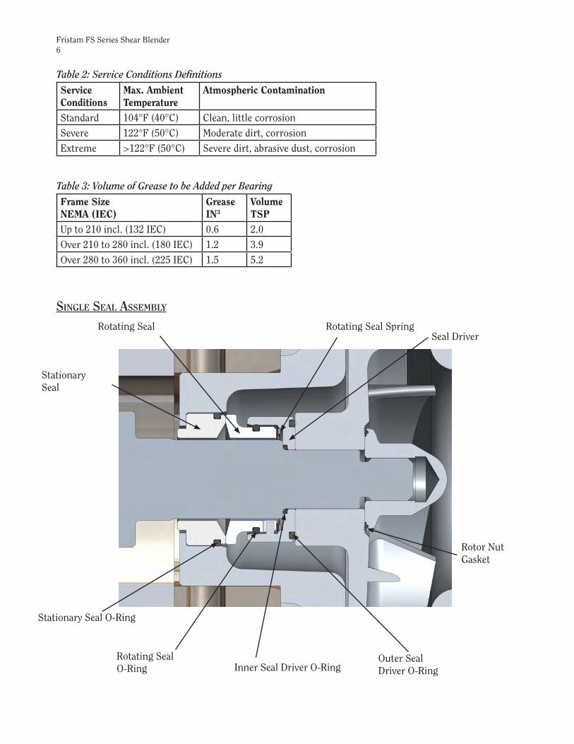
Single Seal aSSeMBly
Rotating Seal O-Ring
Rotor NutGasket
Outer Seal Driver O-RingInner Seal Driver O-Ring
Stationary Seal O-Ring
StationarySeal
Rotating Seal Rotating Seal SpringSeal Driver
Table 2: Service Conditions Definitions
Service Conditions
Max. Ambient Temperature
Atmospheric Contamination
Standard 104°F (40°C) Clean, little corrosionSevere 122°F (50°C) Moderate dirt, corrosionExtreme >122°F (50°C) Severe dirt, abrasive dust, corrosion
Table 3: Volume of Grease to be Added per Bearing
Frame Size NEMA (IEC)
GreaseIN3
VolumeTSP
Up to 210 incl. (132 IEC) 0.6 2.0Over 210 to 280 incl. (180 IEC) 1.2 3.9Over 280 to 360 incl. (225 IEC) 1.5 5.2

Fristam FS Series Shear Blender7
douBle Seal aSSeMBly
RotatingSeal O-Ring
Rotor NutGasket
Outer Seal Driver O-Ring
Inner SealDriver O-Ring
Stationary Seal
Rotating SealRotating Seal Spring
Seal Driver
Flush Seal
StationarySeal O-Rings
Flush Seal O-Ring
FlushSealSpring
Fristam FS Series Shear Blender8
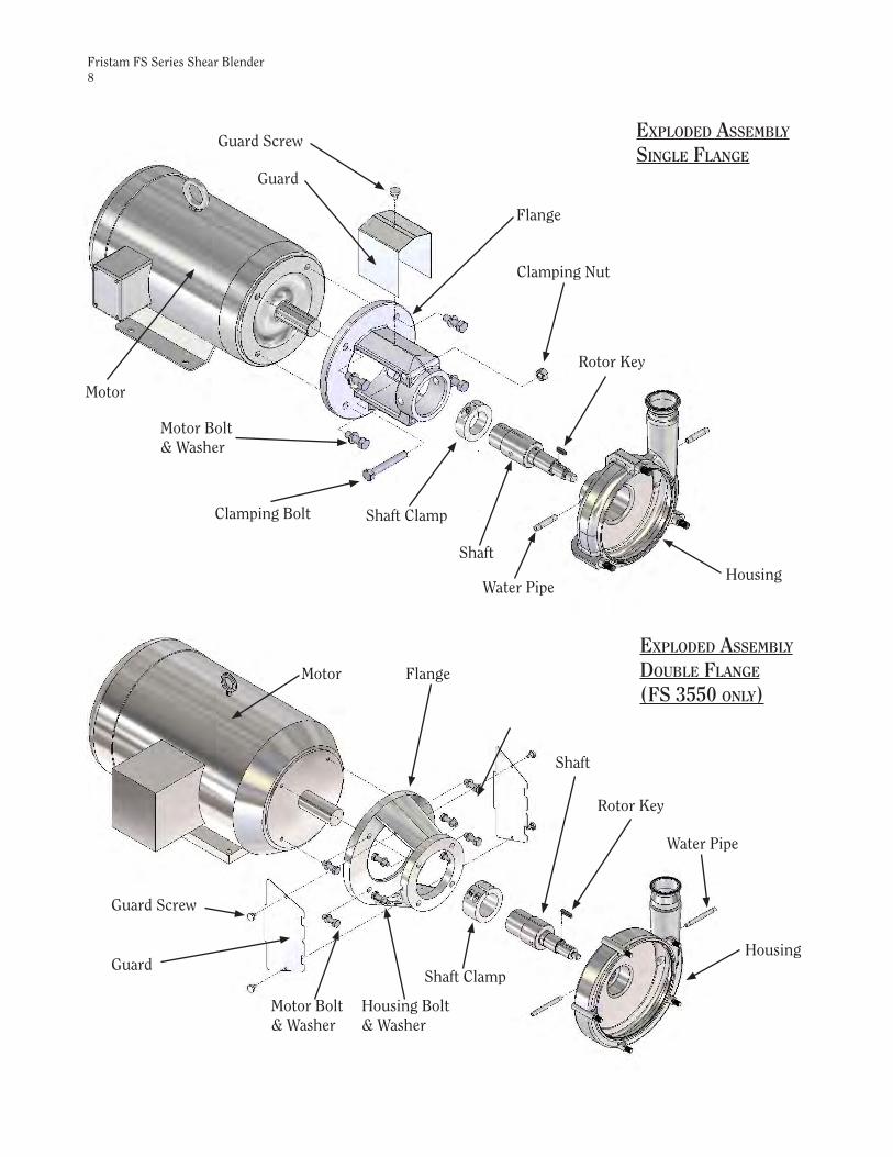
exploded aSSeMBly
Single Flange Guard Screw
Guard
Flange
Clamping Nut
Clamping Bolt
Motor Bolt& Washer
Shaft Clamp
Rotor Key
ShaftHousing
Water Pipe
Motor
Guard Screw
Flange
Shaft Clamp
Rotor Key
Shaft
Housing
Water Pipe
Housing Bolt & Washer
Guard
Motor Bolt & Washer
Motor
exploded aSSeMBly
douBle Flange (FS 3550 only)

Fristam FS Series Shear Blender9
Flush Seal Spring
Flush Seal O-Ring
Flush Seal
Stationary Seal
Stationary Seal O-Rings
Rotating Seal
Rotating Seal O-Ring
Rotating Seal Spring
Outer Seal Driver O-Ring
Seal Driver
Inner Seal Driver O-Ring
Rotor
Rotor Nut Gasket
Rotor Nut
Cover O-Ring
Cover
Cover Nut(Star or Hex)
Inner Stator O-Ring
Outer Stator O-Ring Forcing Screw
(hex bolt or stud with knob)

Fristam FS Series Shear Blender10
Note: When replacing ANY seal part, it is important that ALL seal wear parts are replaced to ensure seal integrity.
Figure 1
Remove flange guard.
Remove cover nuts.
Remove cover and discard cover O-ring.
Remove the stator from the cover by turning the forcing screws clockwise to free the stator from the cover. Remove and discard the stator O-rings.
Seal replaceMent diSaSSeMBly
Figure 2
Place 3/8” rod or Phillips screwdriver in shaft hole. Remove rotor nut. Discard rotor nut gasket.
Remove rotor and discard rotor O-ring.
You may need to insert two long rods or screwdrivers into the holes in the rotor to remove it.
Remove the rotor key.
3/8” Shaft Hole

Fristam FS Series Shear Blender11
Figure 3
Remove seal driver/rotating seal assembly.
Discard rotating seal, O-rings and spring. Do not discrad the seal driver.
Remove and discard the stationary seal and its O-rings.
Double Seal Only: Remove flush seal and flush seal spring and discard.
(Note: to distinguish between the seal springs: FLUSH SEAL SPRING HAS A WHITE STRIPE ON THE OUTSIDE EDGE; ROTATING SEAL SPRING DOES NOT.)
aSSeMBly
Double Seal Only:
Figure 4
Install spring behind shaft pins. Place O-ring into double rotating seal and lubricate. Push seal onto shaft making sure slots align with pins.
(Note: housing and flange removed from picture for clarity)
Flush Seal Components
Rotating Seal SpringFlush Seal Spring

Fristam FS Series Shear Blender12
Figure 5
Single Seal:Install single stationary seal O-ring and lubricate.
Double Seal:Install single and double stationary seal O-rings and lubricate.
Figure 6
Install the stationary seal into housing making sure to align flats on the seal with the flats on the housing.
Figure 7
Install spring behind seal pins inside the seal driver.
Stationary Seal O-ring (single seal)
Align flats onhousing & seal
Stationary Seal O-rings(double seal)

Fristam FS Series Shear Blender13
Figure 9
Slide inner seal driver O-ring onto the shaft and lubricate.
(Note: housing and flange removed from picture for clarity)
Figure 10
Slide seal driver assembly onto the shaft.
(Note: housing and flange removed from picture for clarity)
Figure 8
Install single rotating seal O-ring and lubricate. Slide seal driver onto rotating seal making sure to align pins inside the driver with the slots on the seal.
Inner Seal Driver O-ring

Fristam FS Series Shear Blender14
Figure 11
Install rotor key and outer seal driverO-ring. Lubricate O-ring.
Figure 12
Slide rotor onto shaft making sure to align keyway in rotor with key in the shaft.
Lubricate rotor nut gasket and place it onto the rotor nut.
Thread rotor nut onto shaft. Place 3/8” rod or Phillips screwdriver in shaft hole to prevent it from turning. Use a torque wrench to tighten the rotor nut.
Outer Seal Driver O-ring
Rotor Key

Fristam FS Series Shear Blender15
Figure 14
Install cover O-ring.
Figure 15
Install cover/stator assembly.
Install cover nuts and tighten.
Rotate the shaft to verify that the rotor turns freely.
Install the guard.
Install the water pipe(s) if necessary.
Figure 13
Install the inner and outer stator O-rings.
Find the markings stamped on the stator and on the back of the cover. Install the stator onto the cover, making sure to align the markings so they are face-to-face when assembled together. Tighten the stator nuts with a torque wrench.
Marking

Fristam FS Series Shear Blender16
puMp ShaFt replaceMent
diSaSSeMBlyDisassemble pump as described in Figures 1-3
Figure 16a (single flange only)
Double Seal and Water Cascade Only: Remove the water pipe(s).
Loosen the clamping bolt and nut. Remove the housing.
Figure 16b (double flange only)
Double Seal and Water Cascade Only: Remove the water pipe(s).
Remove the housing bolts and washers. Remove the housing.

Fristam FS Series Shear Blender17
Figure 17
Use an Allen wrench to loosen the shaft clamp cap screw(s). Remove pump shaft.
aSSeMBly
Figure 18
Install new shaft making sure to align the slit in the shaft with the slit in the shaft clamp. Also align the keyway in the motor shaft with the hole in the pump shaft.
Do not tighten the shaft clamp yet.
(Note: flange removed for clarity)
Figure 19a (single flange only)
Install housing hub into the flange. Rotate the inlet to align it with the piping.
Double Seal and Water Cascade Only: Install the water pipe(s).
Use a 3/4” wrench and a 3/4” torque wrench to torque the clamping bolt.
Shaft Clamp Cap Screw
Align slits
Align hole with keyway

Fristam FS Series Shear Blender18
Figure 19b (double flange only)
Install housing hub into the flange. Rotate the inlet to align it with the piping and align bolt holes.
Double Seal and Water Cascade Only: Install the water pipe(s).
Install the lockwashers and bolts. Use a 3/4” torque wrench to torque the bolts.
Figure 20
Place a 0.5mm gapping shim in between the stator and cover and install the stator lockwashers and nuts. The o-rings do not need to be installed on the stator.
Setting rotor-to-Stator gapIf you have removed the pump shaft from the motor shaft for any reason (such as replacing the shaft or motor), you must re-set the gap. Assemble the blender as described in Figures 4-12.

Fristam FS Series Shear Blender19
Figure 21
Install the seal driver. (It is not necessary to install the individual seal components to set the gap.)
Install the cover/stator assembly onto the housing.
Install the cover nuts and tighten.
Push the shaft forward until the rotor contacts the stator.
Figure 22
Make sure to align the slot in the shaft with the slot in the shaft clamp. Also align the keyway in the motor shaft with the hole in the blender shaft.
Tighten the shaft clamp bolt with a torque wrench.
Remove the cover and disassemble the stator.
Remove the gapping shim.
Push
Align slits
Align hole with keyway

Fristam FS Series Shear Blender20
126500008212/10/02
126500008312/10/02
Setting the ShaFt alignMentIf you have removed the pump shaft from the motor shaft for any reason (such as replacing the shaft or motor), you must check the shaft alignment.
Figure 23
Remove the rotor, as described in Figure 2.
Remove the housing, as described in Figure 16.
Using a dial indicator or similar device, measure the shaft alignment. The TIR (Total Indicated Run-out) of the shaft must be within .05mm (.002in).
Figure 24
To adjust run-out, tap the end of the shaft at its high point with a soft-faced hammer until it is within the tolerance.
Re-check the shaft collar torque.
Re-install the housing.
Continue the installation process as described in Figures 12-15.

Fristam FS Series Shear Blender21
Motor replaceMent
diSaSSeMBlyDisassemble pump as described in figures 1-3. Remove housing and shaft as described in figures 15-17.
Figure 25
Use a socket to remove the motor bolts and washers. Remove the flange.
aSSeMBlyReplace motor. Install flange onto motor. Replace bolts and washers. Use a torque wrench to tighten the bolts to the correct torque (see page 4 for torque values).
Install shaft and housing as described in figures 18-19.
Assemble seal as described in figures 4-11.
Set rotor-to-stator gap as described in figure 20-22.
Install cover O-ring, cover/stator assembly, and cover nuts as described in figures 13-15.
Replace guard(s) and water pipe(s) if necessary.

Fristam FS Series Shear Blender22
inStallation
unpackingCheck the contents and all wrapping when unpacking the pump. Inspect the pump carefully for any damage that may have occurred during shipping. Immediately report any damage to the carrier. Remove the shaft guard and rotate the pump shaft by hand to make sure the rotor rotates freely. Keep the protective caps over the pump inlet and outlet in place until you are ready to install the pump.
inStallingPrior to actually installing the pump, ensure that:• The pump will be readily accessible for maintenance, inspection and cleaning.
• Adequate ventilation is provided for motor cooling.
• The drive and motor type is suitable for the environment where it is to be operated. Pumps intended for use in hazardous environments (i.e. explosive, corrosive, etc.) must use a motor and drive with the appropriate enclosure characteristics. Failure to use an appropriate motor type may result in serious damage and/or injury.
piping guidelineSThis section describes good piping practices to obtain maximum efficiency and service life from your pump.
Maximum performance and trouble-free operation require adherence to good piping practices.• Ensuring proper piping support and alignment at both the suction inlet and discharge
outlet can help prevent serious damage to the pump housing (Figure 23).
• Avoid abrupt transitions in the piping system (Figure 24).
• Avoid throttling valves in the suction piping.
• Keep suction lines as short and direct as possible.
• Ensure that the NPSH available in the system is greater than NPSH required by the pump.
• Avoid sump areas where sediments may collect (Figure 25). Figure 24
Figure 25
Figure 23

Fristam FS Series Shear Blender23
• Avoid the formation of air pockets in the piping (Figure 26).
• Avoid abrupt closure of shut-off valves, this may cause hydraulic shock which can cause severe damage to the pump and system.
• Avoid elbows in the suction line if possible. When necessary they should be located 5 pipe diameters away from the pump inlet, and have a bend radius greater than 2 pipe diameters (Figure 27).
• Check valves in discharge line should be a minimum of 5 ft. away from the pump outlet (Figure 27).
electrical inStallation
We use standard duty TEFC motors unless otherwise specified. Many motor options are available: washdown, flameproof, explosion proof, hostile duty or chemical duty.
The motor selected should meet the requirements of the specified operating conditions. A change in conditions (for example, higher viscosity, higher specific gravity, lower head losses) can overload the motor. When changing operating conditions or whenever there is any doubt, please contact Fristam Pumps, Inc., for technical assistance.
Have an electrician connect the motor using sound electrical practices. Provide adequate protection. Pumps fitted with mechanical seals must not run dry, not even momentarily. Determine the direction of rotation by watching the motor fan, which must turn clockwise.
puMp operationS
Start-up inStructionS• Remove any foreign matter that may have entered the pump.
• Do not use the pump to flush the system!
• Check pump for proper rotation as indicated on the pump. Proper motor direction is clockwise when looking at the fan end of the motor. (NOTE: When checking the direction of rotation, the pump must be full of liquid.)
• Never run the pump dry, even momentarily. Seal damage can result.
Shut-down inStructionS• Shut off the power supply to the pump.
• Close the shut-off valves in the suction and discharge piping.
• Drain and clean the pump.
• Protect the pump against dust, heat, moisture and impact damage.
Figure 27
Figure 26

Fristam FS Series Shear Blender24
inStallation oF water FluSh For douBle Mechanical Seal
Set up the water flush for the double mechanical seal as shown (Figure 28). Use only between 1-2 gallons per hour of water at a maximum pressure of 5 PSI. Excessive flow of water through the seal increases the pressure inside the seal. Note: maximum pressure inside the seal is 5 PSI. Excessive flow/pressure through the seal flush will cause excessive wear and shorten seal life.
Pipe the exit side of the water flush with 2 -5 feet physical height of tubing. This ensures that some water is always in the center seal and the seal never runs dry.
It is possible to inject steam through the center seal (within the pressure requirements). We do not recommend using steam alone for the cooling/lubricating of the seal.
It is desirable to have the flush water on the outlet side visible. This allows an easy check to see that the flush water is on and also if the seal is functioning properly. In a malfunctioning seal the flush water will disappear, become discolored, or show an unusual increase in flow. If these conditions exist, check the seal and replace if necessary.
inStallation oF water caScade
The water cascade (if supplied) is piped through the hub of the pump housing and into the stationary seal. Since there is no rear seal, the flush water will exit through the rear of the seal area (Figure 29).
Not all FPR pumps require a water cascade on the seal.
Use about 1-2 gallons per hour of water at a maximum pressure inside the seal of 5 psi.
COOLING WATER IN
WATER PIPE CONNECTIONSFOR DOUBLE SEALS
1/8" N.P.T.
THROTTLE THIS VALVETO 1-2 GAL/HR
VISIBLE WATERFLOW
TO DRAIN
2-5 FEET
IL-01737/7/00
Figure 28
Figure 29

Fristam FS Series Shear Blender25
puMp Maintenance record
date Service perForMed By

Fristam FS Series Shear Blender26
puMp Maintenance record
date Service perForMed By

Fristam FS Series Shear Blender27
notice oF terMS, warranty proviSionS
including diSclaiMerS, claiMS and liMitation oF liaBility
Prices and all terms and conditions of sale are established in current price sheets and are subject to change without notice. All orders are subject to acceptance by Fristam Pumps USA, Limited Partnership.Each Fristam Pumps item is warranted to be free from manufacturing defects for a period of one (1) year from the date of shipment, providing it has been used as recommended and in accordance with recognized piping practice, and providing it has not been worn out due to severe service, such as encountered under extremely corrosive or abrasive conditions.This warranty is expressly in lieu of any other warranties expressed or implied, including but not limited to, any implied warranty of merchantability or fitness for particular purpose. All other warranties whatsoever, expressed or implied by law or otherwise, are hereby excluded.All claims must be in writing and must be mailed or delivered by purchaser within thirty (30) days after purchaser learns of the facts upon which such claim is based. Any claim not made in writing and within the time period specified above shall be deemed waived.Purchaser’s sole and exclusive remedy and Fristam Pumps maximum liability for claims arising hereunder or for negligence for any and all losses and damages resulting from any cause shall be either the repair or replacement of defective items or, at Fristam Pumps’ option, the refund of the purchase price for such items. In no event, including in the case of a claim for negligence, shall Fristam Pumps be liable for incidental or consequential damages, including loss of profits. No person, including any representative employee or agent of Fristam Pumps is authorized to assume on behalf of Fristam Pumps any liability or responsibility in addition to or different from that described in this provision. Any and all representations, promises, warranties or statements that are in addition to or different from the terms of this provision are of no force or effect.If any provision of this Notice is held to be invalid, such provision shall be severed and the remaining provisions shall continue to be in force.

© Copyright 2013 - Fristam Pumps USA Limited PartnershipDrawing # 1250000022 Updated 8/12/13Part # 1050000216Visit www.fristam.com for a current list of literature.
2410 Parview Road • Middleton, WI 53562-25241-800-841-5001 • 608-831-5001Website: www.fristam.comEmail: [email protected]