instruction and operation manual - labxphotos.labwrench.com/equipmentmanuals/16092-6088.pdf ·...
TRANSCRIPT
INSTRUCTION AND OPERATION MANUAL MODEL CP-350C AND CP-350T
`TURBO-KLEEN` TABLET DEDUSTER / CAPSULE POLISHER
KEY INTERNATIONAL, INC. 480 ROUTE 9
ENGLISHTOWN, N.J. 07726 (732) 536-1500
FAX (732) 972-2630 E-Mail [email protected]
CP-350C AND CP-350T INSTRUCTION MANUAL
CONTENTS: SECTION Introduction and Operation: 1.0 Assembly and Disassembly: 2.0 Brush Care: 3.0 Adjustments and Misc.: 4.0 Specifications: 5.0 Graphics (photos): 6.0 Drawings and Parts List: 7.0 Materials of Construction and Contact Areas 8.0 Maintenance 9.0
Updated December 2003
SECTION 1.0 INTRODUCTION
The Key International, Inc. CP-350C and CP-350T Tablet Deduster / Capsule Polisher are precision machines using the rotating brush concept to clean tablets / capsules on a continuous basis, directly from a tablet press or a capsule filling machine, or by hand feeding. They are designed with GMP (Good Manufacturing Practices) throughout. All metal contact parts are fabricated from stainless steel. All plastic parts are in compliance with FDA requirements for food contact. EXPLAINATION OF MODEL DIFFERENCES The CP-350C is designed for cleaning, dedusting and polishing Capsules whereas the CP-350T is used for processing Tablets. The only differences between to two models are that the CP-350C comes with a 10 mesh polishing net with a perforated support tube designed for use with a net and a stainless steel infeed baffle cover. The CP-350T does not have a polishing net and comes with a straight type perforated tube and a white Delrin infeed baffle cover. The reasons for the differences are that capsules are a bit more rugged and clean well when brushed against the polishing net. Tablets however need to be handled with more care and can be damaged if brushed against the polishing net. In addition, should a tablet find its way between the brush and the infeed baffle cover, it could be damaged if it rubs against stainless steel. Therefore, a softer Delrin baffle cover is used.
Updated December 2003
SECTION 1.0 (Continued) Item KEY Part No. 10 Mesh Polishing Net 2-073-0002 Perforated Tube (for use with net) 2-073-0014 Net Retainer Pin 2-073-0008 Infeed Baffle Cover (stainless steel) 2-072-0073A Perforated Tube (for use without net) 2-073-0015 Infeed Baffle Cover (Delrin) 2-072-0073P All other machine components are the same. OPERATION
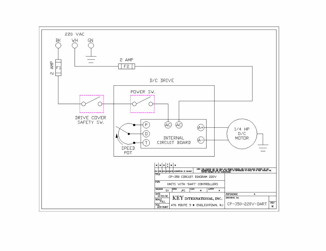
The CP-350C and CP-350T Capsule Polishers are equipped with a 1/4 HP permanent magnet motor which has variable speed capability through a direct current motor controller. They operate on 110 volt, 60 cycles, single-phase electrical power supply. (See Safety Precautions). Note: If the optional 220-volt, single-phase motor is supplied, the HP is 1/3. Also, no male plug is supplied on the power cord. User must supply plug to match users particular female receptacle. The motor controller is mounted to the side of the main frame. It has an ON - OFF switch and a variable speed control knob. Included (inside the washdown enclosure) is an in-line (4 amp) time delay fuse. Note: As standard, the CP-350C and CP-350T include NEMA 4 motors with waterproof controllers for direct contact from a water hose. In addition, all fasteners are stainless steel, with all other metals being either anodized aluminum or nickel-plated. Several `Weep-Holes` are located where needed for drainage.
Updated December 2003
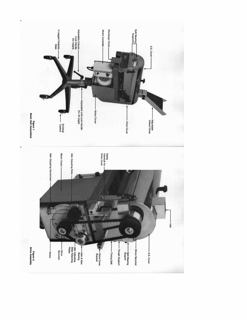
SECTION 2.0 DISASSEMBLY
1. Remove the infeed hopper or the adjustable infeed chute. 2. Remove the drive cover. 3. Remove the stainless steel cover with end plates. 4. Loosen the idler adjusting hand knob and move the idler adjusting slide to the left to slacken the timing belt. 5. Remove the timing belt. 6. Lift out the perforated tube with the brush shaft and net assembly. Remove the rotary elbow from the shaft if supplied. 7. Slide the brush and brush shaft out of the perforated tube. 8. Slide the hex bore bearing off the end. Remove the discharge end brush lock by loosening the setscrew. 9. Turn the brush 1/4 turn to disengage it from the infeed end brush lock. Slide the brush off of the shaft. 10. Collapse the net by taking the hinge out of the channel and lifting into the center of the tube. Slide the net and the hinge lock pin assembly carefully from the perforated tube. If the unit is supplied with a `Coil Flite`, remove it first. 11. Remove the hinge lock pin from the net. 12. Lift the trough from its support. 13. Thoroughly clean all of the parts removed. ASSEMBLY IS THE DIRECT REVERSE OF PREVIOUS SEQUENCE. Note: See section on the proper installation of the infeed baffle, the brush lock and the infeed baffle cover. If the unit is equipped with a `Coil Flite`, the net should be assembled with the hinge lock pin and inserted into the perforated tube first. Then carefully turn the `Coil Flite` into the net and tube assembly. Take note that the `Coil Flite` position does not extend past the infeed opening; otherwise, it could restrict the feeding of the capsules.
Updated December 2003
SECTION 2.0 (Continued) DUAL BRUSH ASSEMBLY
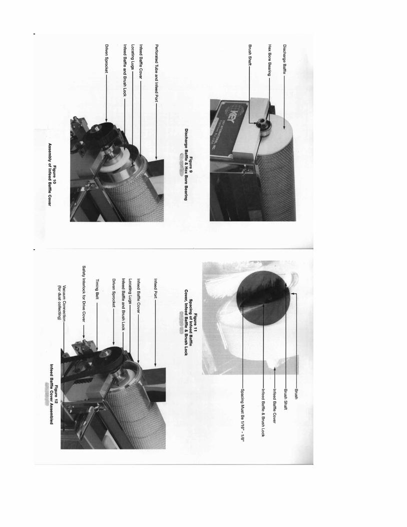
The dual brush assists in cleaning the ends and center area of more difficult type products. One brush is larger in diameter and has a softer bristle. The other brush is smaller with a stiffer bristle. To assemble, turn the smaller brush into the larger one by `screwing` them together. Then, slide the assembled two brushes over the shaft. The larger diameter brush channel should be placed into the infeed baffle brush lock. The smaller diameter brush will lie next to the baffle brush lock. Slide the dual brush discharge end lock onto the shaft and engage both brush channels. With the lock engaged with the two brushes, hold the baffle end and twist 1/4 turn to provide tension. Note: Before tightening of the discharge end brush lock, be certain that it is positioned approximately 1/4” from the bearing shoulder. ASSEMBLY OF INFEED BAFFLE COVER
The infeed baffle brush lock should be assembled onto the shaft so that it is a distance of 3/8” from the bearing step on the shaft. This location has been set at the factory and `spot-drilled` for ease when re-assembling. Next, slide the baffle cover into place. Leave it loose for final assembly later with the perforated tube. Next, install brush over the shaft. (See section on brush care and assembly). This brush and shaft sub-assembly is placed into the perforated tube and net sub-assembly. (See section on proper net installation). Make certain that the infeed port end of the perforated tube is placed over the discharge end of the shaft (Figure 10). Carefully insert the baffle cover inside of the net so that the lugs are positioned against the end of the perforated tube (Figure 12). Be careful not to push the net out of position. If all the assembly procedures have been carefully followed, the resulting space between the infeed baffle cover and the infeed baffle should be between 1/16” to 1/8” (Figure 11). If this distance is too large, the capsules could be trapped and/or damaged. If the distance is too small, the two pieces will rub together and wear. PROPER NET ASSEMBLY (Figure 7):
The nets are supplied with a natural curve to the direction of assembly with the hinge-locking pin. If this curve is not obvious, then match the net to the perforated tube, aligning the infeed and discharge openings in the net. Insert the hinge lock pin (fig.7) alternately through the hinged portion of the net to form a cylindrical shape.

SECTION 2.0 (Continued) Collapse the hinged section into the assembled net to make a smaller diameter cylindrical shape and insert into the perforated tube. Orient the collapsed net with the hinged locking channel (Fig.6). When the net is expanded inside the tube, the hinge lock pin will lay into the channel. This will require some hand forming of the net inside the perforated tube due to the required close fit. Notes:
Updated December 2003
SECTION 3.0 BRUSH CARE
The nylon brush bristles are subject to damage and will take a `set` if allowed to lie on a surface without being supported. We suggest supporting the brush, after cleaning, by one of its ends and allowing it to hang free while drying. When storing spare brushes, place them in a 4 1/4” I.D. tube and store vertically. If brush becomes damaged and takes a `set`, place it in hot water for 15 to 20 minutes and hang as previously noted until dry. To assemble the brush properly, slide it over the shaft up to the infeed end. Turn it 1/4 turn to lock into the infeed baffle and brush lock. Then slide the discharge end brush lock onto the shaft and turn 1/4 turn to engage the end of the brush. Once engaged, hold the baffle end and twist clockwise 1/4 turn to apply tension. Before the tightening of the discharge end brush lock, be certain it is positioned approximately 1/4” from the bearing shoulder.
Updated December 2003
SECTION 4.0
INFEED HEIGHT ADJUSTMENTS
The CP-350 provides you with two angular adjustments: the infeed chute and the angle of the machine itself. The best angle settings will depend on the discharge height of the capsule filler, so to obtain a smooth, continuous feed into the polisher. MOTOR SPEED ADJUSTMENT
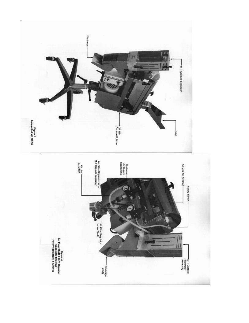
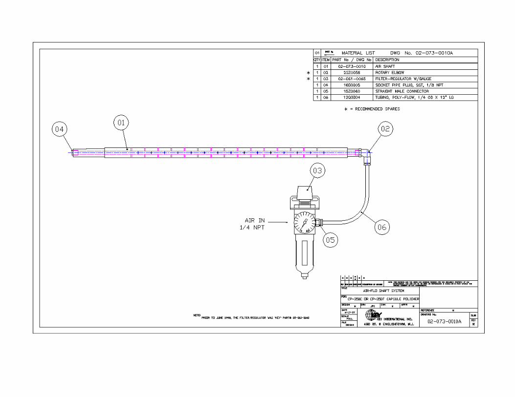
A variable speed drive is provided so you can vary the length of time that the product will be polished. The proper time depends on the size and quantity of dust on the product. We suggest that you start at mid-range and adjust as necessary. AIR FLO ATTACHMENT
The optional airshaft provides for distribution of air inside of the chamber, which assists in cleaning the brush and net. The air regulator / filter varies the setting of the airflow. The amount of air needed depends on the particular product. DO NOT use more air then the amount of vacuum being pulled dust nozzle. If this condition occurs, powder will be blown out of the inlet and discharge areas. As an option, KEY International, offers a `Static Eliminator`, which greatly aids in reducing static, thus allowing the dust to be removed with greater ease.
Updated December 2003
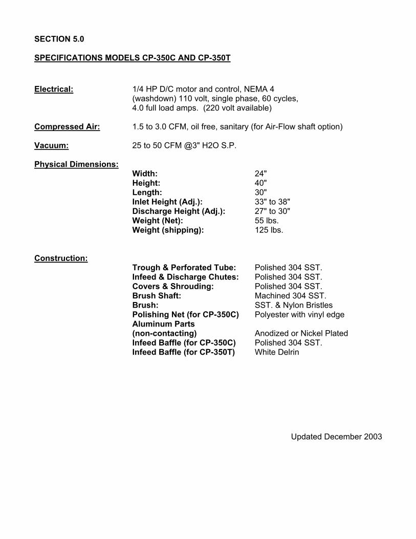
SECTION 5.0 SPECIFICATIONS MODELS CP-350C AND CP-350T
Electrical: 1/4 HP D/C motor and control, NEMA 4 (washdown) 110 volt, single phase, 60 cycles, 4.0 full load amps. (220 volt available) Compressed Air: 1.5 to 3.0 CFM, oil free, sanitary (for Air-Flow shaft option) Vacuum: 25 to 50 CFM @3" H2O S.P. Physical Dimensions: Width: 24" Height: 40" Length: 30" Inlet Height (Adj.): 33" to 38"
Discharge Height (Adj.): 27" to 30" Weight (Net): 55 lbs. Weight (shipping): 125 lbs.
Construction: Trough & Perforated Tube: Polished 304 SST. Infeed & Discharge Chutes: Polished 304 SST. Covers & Shrouding: Polished 304 SST. Brush Shaft: Machined 304 SST. Brush: SST. & Nylon Bristles Polishing Net (for CP-350C) Polyester with vinyl edge Aluminum Parts
(non-contacting) Anodized or Nickel Plated Infeed Baffle (for CP-350C) Polished 304 SST. Infeed Baffle (for CP-350T) White Delrin
Updated December 2003

SECTION 6.0 GRAPHICS Please note that improvements and upgrades are constantly being made, which may result in several of the following photos appearing slightly different then what is currently being supplied.


SECTION 7.0 DRAWINGS AND PARTS LISTS


SECTION 8.0
Certificate of Product Contacting Materials and Contacting Surface Areas
For KEY Models CP-350C and CP-350T Capsule Polishers
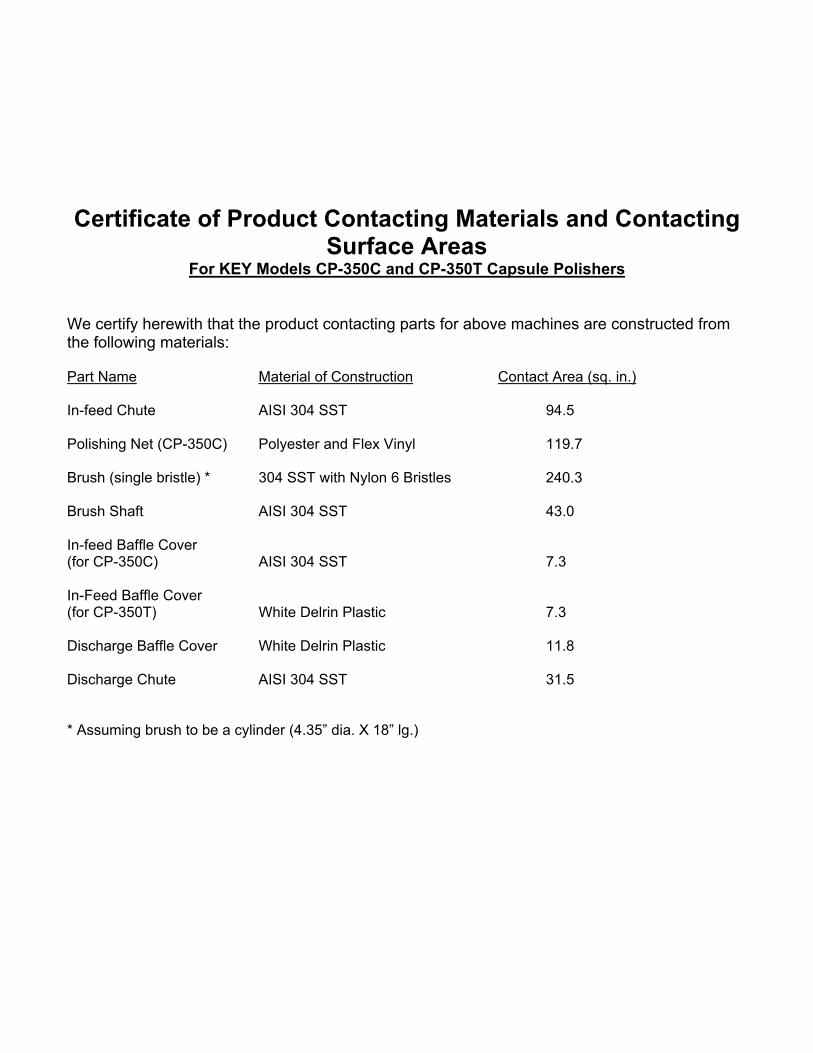
We certify herewith that the product contacting parts for above machines are constructed from the following materials: Part Name Material of Construction Contact Area (sq. in.) In-feed Chute AISI 304 SST 94.5 Polishing Net (CP-350C) Polyester and Flex Vinyl 119.7 Brush (single bristle) * 304 SST with Nylon 6 Bristles 240.3 Brush Shaft AISI 304 SST 43.0 In-feed Baffle Cover (for CP-350C) AISI 304 SST 7.3 In-Feed Baffle Cover (for CP-350T) White Delrin Plastic 7.3 Discharge Baffle Cover White Delrin Plastic 11.8 Discharge Chute AISI 304 SST 31.5 * Assuming brush to be a cylinder (4.35” dia. X 18” lg.)
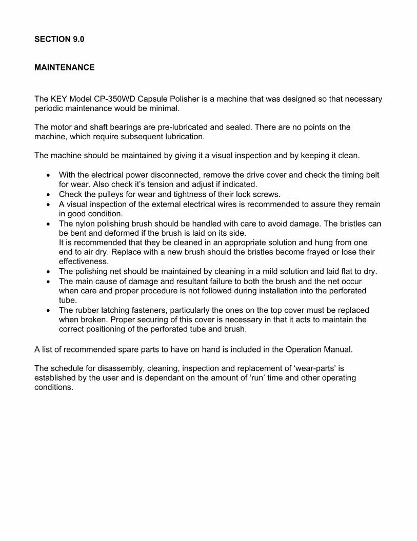
SECTION 9.0 MAINTENANCE The KEY Model CP-350WD Capsule Polisher is a machine that was designed so that necessary periodic maintenance would be minimal. The motor and shaft bearings are pre-lubricated and sealed. There are no points on the machine, which require subsequent lubrication. The machine should be maintained by giving it a visual inspection and by keeping it clean.
• With the electrical power disconnected, remove the drive cover and check the timing belt for wear. Also check it’s tension and adjust if indicated.
• Check the pulleys for wear and tightness of their lock screws. • A visual inspection of the external electrical wires is recommended to assure they remain
in good condition. • The nylon polishing brush should be handled with care to avoid damage. The bristles can
be bent and deformed if the brush is laid on its side. It is recommended that they be cleaned in an appropriate solution and hung from one end to air dry. Replace with a new brush should the bristles become frayed or lose their effectiveness.
• The polishing net should be maintained by cleaning in a mild solution and laid flat to dry. • The main cause of damage and resultant failure to both the brush and the net occur
when care and proper procedure is not followed during installation into the perforated tube.
• The rubber latching fasteners, particularly the ones on the top cover must be replaced when broken. Proper securing of this cover is necessary in that it acts to maintain the correct positioning of the perforated tube and brush.
A list of recommended spare parts to have on hand is included in the Operation Manual. The schedule for disassembly, cleaning, inspection and replacement of ‘wear-parts’ is established by the user and is dependant on the amount of ‘run’ time and other operating conditions.
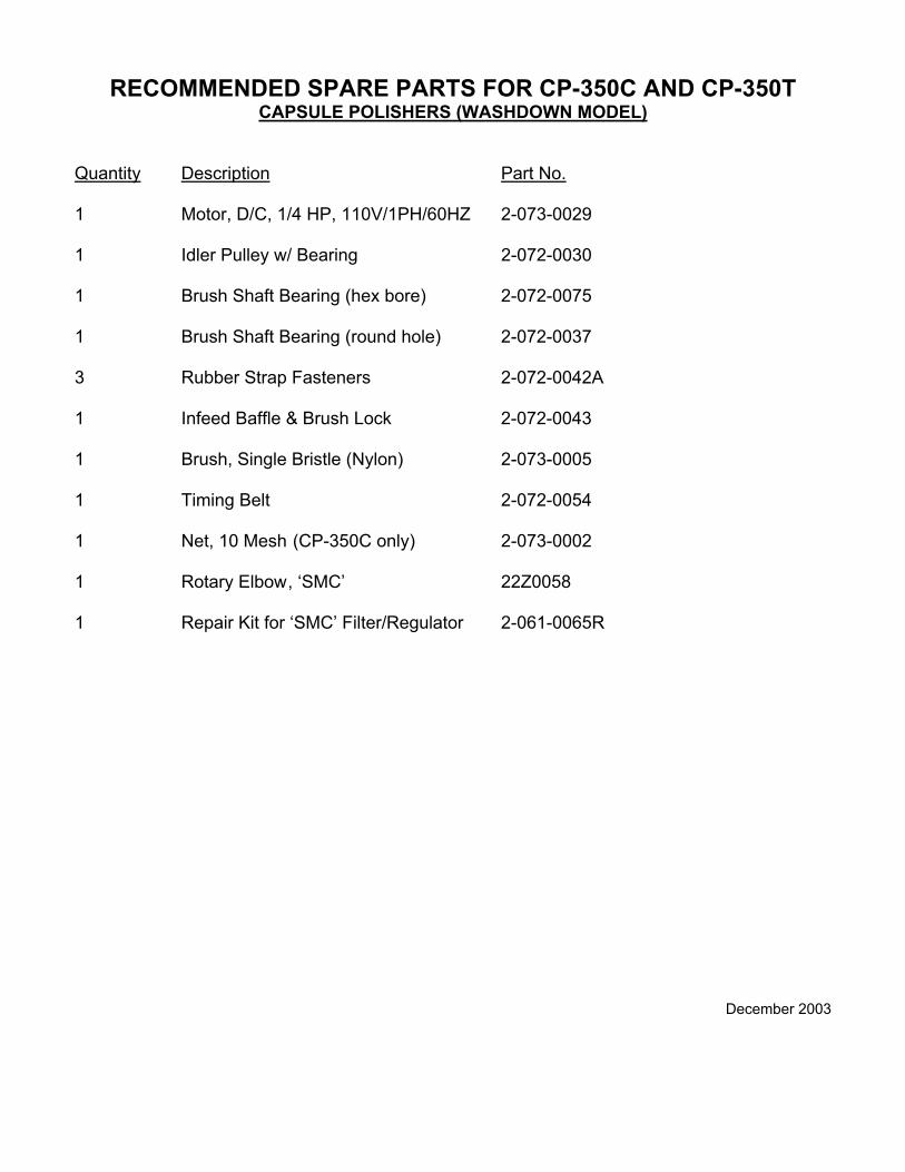
RECOMMENDED SPARE PARTS FOR CP-350C AND CP-350T CAPSULE POLISHERS (WASHDOWN MODEL)
Quantity Description Part No. 1 Motor, D/C, 1/4 HP, 110V/1PH/60HZ 2-073-0029 1 Idler Pulley w/ Bearing 2-072-0030 1 Brush Shaft Bearing (hex bore) 2-072-0075 1 Brush Shaft Bearing (round hole) 2-072-0037 3 Rubber Strap Fasteners 2-072-0042A 1 Infeed Baffle & Brush Lock 2-072-0043 1 Brush, Single Bristle (Nylon) 2-073-0005 1 Timing Belt 2-072-0054 1 Net, 10 Mesh (CP-350C only) 2-073-0002 1 Rotary Elbow , ‘SMC’ 22Z0058 1 Repair Kit for ‘SMC’ Filter/Regulator 2-061-0065R
December 2003