instruction bulletin powerlogic energy meter communication
TRANSCRIPT

Instruction Bulletin63230-216-213/A1
6/2001
POWERLOGIC® Energy Meter Communication BoardInstallation
Z102878-0A

© 2001 Schneider Electric All Rights Reserved
Read these instructions carefully and look at the equipment to become familiar with the device before trying to install, operate, service, or maintain it. The following special messages may appear throughout this bulletin or on the equipment to warn of potential hazards or to call attention to information that clarifies or simplifies a procedure.
The addition of either symbol to a “Danger” or “Warning” safety label indicates that an electrical hazard exists which will result in personal injury if the instructions are not followed.
This is the safety alert symbol. It is used to alert you to potential personal injury hazards. Obey all safety messages that follow this symbol to avoid possible injury or death.
NOTE: Provides additional information to clarify or simplify a procedure.
Electrical equipment should be installed, operated, serviced, and maintained only by qualified personnel. This document is not intended as an instruction manual for untrained persons. No responsibility is assumed by Schneider Electric for any consequences arising out of the use of this manual.
This equipment has been tested and found to comply with the limits for a Class A digital device, pursuant to part 15 of the FCC Rules. These limits are designated to provide reasonable protection against harmful interference when the equipment is operated in a commercial environment. This equipment generates, uses, and can radiate radio frequency energy and, if not installed and used in accordance with the instruction manual, may cause harmful interference to radio communications. Operation of this equipment in a residential area is likely to cause harmful interference in which case the user will be required to correct the interference at his own expense.
NOTICE
!
DANGER indicates an imminently hazardous situation which, if not avoided, will result in death or serious injury.
DANGER
WARNINGWARNING indicates a potentially hazardous situation which, if not avoided, can result in death or serious injury.
CAUTIONCAUTION indicates a potentially hazardous situation which, if not avoided, can result in minor or moderate injury.
CAUTIONCAUTION, used without the safety alert symbol, indicates a potentially hazardous situation which, if not avoided, can result in property damage.
PLEASE NOTE
Class A FCC Statement

63230-216-213/A1 Contents6/2001
© 2001 SSchneider Electric All Rights Reserved
CONTENTS
CONTENTS . . . . . . . . . . . . . . . . . . . . . . . . . . . . . . . . . . . . . . . . . . . . . . . . ICHAPTER 1—INTRODUCTION . . . . . . . . . . . . . . . . . . . . . . . . . . . . . . . . 1
OVERVIEW . . . . . . . . . . . . . . . . . . . . . . . . . . . . . . . . . . . . . . . . . . . . . . . . . 1
WHAT IS AN ENERGY METER COMMUNICATION CARD? . . . . . . . . . . 2
Specifications . . . . . . . . . . . . . . . . . . . . . . . . . . . . . . . . . . . . . . . . . . . . 2
CHAPTER 2—SAFETY PRECAUTIONS . . . . . . . . . . . . . . . . . . . . . . . . . . 3
CHAPTER 3—INSTALLATION . . . . . . . . . . . . . . . . . . . . . . . . . . . . . . . . . 5
DESCRIPTION . . . . . . . . . . . . . . . . . . . . . . . . . . . . . . . . . . . . . . . . . . . . . . 5
SELECTING THE NETWORK ADDRESS—MODBUS ADDRESS DIP SWITCHES . . . . . . . . . . . . . . . . . . . . . . . . . . . . . . . . . . . . . . . . . . . . . . . . . 7
SELECTING WIRING TYPE, BAUD RATE, AND PARITY—COMMUNICATION DIP SWITCHES . . . . . . . . . . . . . . . . . . . . . . . . . . . . . 7
RS-485 COMMUNICATIONS . . . . . . . . . . . . . . . . . . . . . . . . . . . . . . . . . . . 8Daisy Chain Maximum Distances . . . . . . . . . . . . . . . . . . . . . . . . . 8
Wiring the RS-485 Communications Connector . . . . . . . . . . . . . . . . . 9Terminating the EMCB . . . . . . . . . . . . . . . . . . . . . . . . . . . . . . . . . . . 11
INSTALLING THE EMCB . . . . . . . . . . . . . . . . . . . . . . . . . . . . . . . . . . . . . 12
CHAPTER 4—TROUBLESHOOTING . . . . . . . . . . . . . . . . . . . . . . . . . . . 15
APPENDIX A—MODBUS ADDRESS DIP SWITCH SETTINGS . . . . . . . 17
INDEX . . . . . . . . . . . . . . . . . . . . . . . . . . . . . . . . . . . . . . . . . . . . . . . . . . . . 19
i

Contents 63230-213-216/A16/2001
ii
© 2001 Schneider Electric All Rights Reserved
63230-216-213/A1 Chapter 1—Introduction6/2001 Overview
© 2001 Schneider Electric All Rights Reserved
CHAPTER 1—INTRODUCTION
OVERVIEW
This document contains installation and operation instructions for the POWERLOGIC® Energy Meter Communication Card (EMCB). Before installing the EMCB (shown in Figure 1–1), you should have a general understanding of the POWERLOGIC Power Monitoring and Control System and related products and technology.For more information about the POWERLOGIC System, refer to the following documents:
• POWERLOGIC System Architecture and Application Guide• POWERLOGIC System Manager Software 3000 Setup Guide
• POWERLOGIC Energy Meter Instruction Bulletin
Figure 1–1: Energy Meter Communication Card
1

Chapter 1—Introduction 63230-216-213/A1What is an Energy Meter Communication Card? 6/2001
2
WHAT IS AN ENERGY METER COMMUNICATION CARD?
Specifications
The POWERLOGIC Energy Meter Communication Card (EMCB) is an optional field-installable card for the POWERLOGIC Energy Meter. The EMCB provides a means for MODBUS RTU protocol. The EMCB also enables the energy meter to provide true kW demand information.
The easy-to-install EMCB thus provides a simple, cost-effective way to network energy meters.
Table 1–1 lists the specifications of the EMCB.
Table 1–1: EMCB Specifications
Communications MODBUS
Output Type MODBUS RTU
Connection 2-wire or 4-wire selectable
Baud Rate 2400, 4800, 9600, 19200
Parity None/Odd/Even selectable
Address 1–63
Displayed Data:
Energy kWh
Real Power kW, per phase and total
Reactive Power kVar, total
Power Factor per phase and total
Max Power kW max
Voltage (V) per phase and average
Current (A) phase and average
Demand kWD
Agency Compliance UL, CUL
© 2001 Schneider Electric All Rights Reserved
63230-216-213/A1 Chapter 2—Safety Precautions6/2001
© 2001 Schneider Electric All Rights Reserved
CHAPTER 2—SAFETY PRECAUTIO
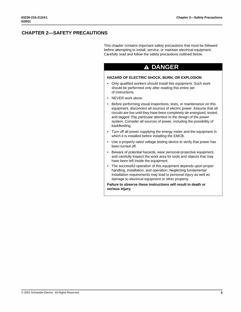
This chapter contains important safety precautions that must be followed before attempting to install, service, or maintain electrical equipment. Carefully read and follow the safety precautions outlined below.
NS
HAZARD OF ELECTRIC SHOCK, BURN, OR EXPLOSION
• Only qualified workers should install this equipment. Such work should be performed only after reading this entire set of instructions.
• NEVER work alone.
• Before performing visual inspections, tests, or maintenance on this equipment, disconnect all sources of electric power. Assume that all circuits are live until they have been completely de-energized, tested, and tagged. Pay particular attention to the design of the power system. Consider all sources of power, including the possibility of backfeeding.
• Turn off all power supplying the energy meter and the equipment in which it is installed before installing the EMCB.
• Use a properly rated voltage testing device to verify that power has been turned off.
• Beware of potential hazards, wear personal protective equipment, and carefully inspect the work area for tools and objects that may have been left inside the equipment.
• The successful operation of this equipment depends upon proper handling, installation, and operation. Neglecting fundamental installation requirements may lead to personal injury as well as damage to electrical equipment or other property.
Failure to observe these instructions will result in death or serious injury.
DANGER
3

Chapter 2—Safety Precautions 63230-216-213/A16/2001
4
© 2001 Schneider Electric All Rights Reserved
63230-216-213/A1 Chapter 3—Installation6/2001 Description
© 2001 Schneider Electric All Rights Reserved
CHAPTER 3—INSTALLATION
DESCRIPTION
�
� �
This section identifies EMCB components and provides installation instructions. Figure 3–1 shows the components of the EMCB. Table 3–1 identifies those components and explains their functions. If the LEDs are not functioning correctly, see “Troubleshooting” on page 15 for instructions.
Figure 3–1: Bottom view of the EMCB, illustrating communication points
�
� � �
�
5

Chapter 3—Installation 63230-216-213/A1Description 6/2001
6
This section describes the communications settings you must make to the EMCB. When daisy-chaining MODBUS devices, follow these guidelines:
• You can connect up to 32 MODBUS devices on a single daisy chain. A maximum of 63 devices can be connected to the daisy chain if an RS-485 repeater is installed.
• Each MODBUS device on the daisy chain must have a unique address. Before connecting the EMCB to the RS-485 communication wires, set the address according to directions in “Selecting the Network Address—MODBUS Address DIP Switches” on page 7. If you assign the same address to two devices, neither device will communicate.
• Set the wiring type, baud rate, and parity according to directions in “Selecting Wiring Type, Baud Rate, and Parity—Communication DIP Switches” on page 7. The settings for each EMCB must match the other devices on its daisy chain.
• For MODBUS cables, use shielded, twisted-pair wire. (For 4-wire use Belden Cable 8723 or 9847or equivalent. For 2-wire use Belden 9841 or equivalent.)
• Terminate the last device on the daisy chain. If the EMCB is the last device, see instructions in “Terminating the EMCB” on page 11.
Table 3–1: Energy Meter Communication Board Components
Ref. No.
Item Description
1RS-485 LED (TX) Red LED; blinks to indicate that the EMCB is reciving
data from the master.
2RS-485 LED (RX) Red LED; blinks to indicate that the EMCB is
transmitting data to the master.
3LED from main board (RX)
Green LED; blinks to indicate that the EMCB is receiving data from the main board.
4LED from main board (TX)
Green LED; blinks to indicate that the EMCB is transmitting data to the main board.
5“Alive” LED Green LED; should blink once per second to indicate
normal operation of the EMCB.
6MODBUS address DIP switches
Use these DIP switches to set the network address for the EMCB.
7Male connection to energy meter
Install the EMCB in the energy meter by inserting this connector into the connection slot of the energy meter.
8Communication DIP switches
Use these DIP switches to set the EMCB wiring type, baud rate, and parity.
9
RS-485 communication terminals
Insert the RS-485 connector into these terminals. See Figure 3–4 on page 9 and Figure 3–5 on page 10 for instructions on wiring the connector for 2-wire or 4-wire communication.
10End of demand subinterval terminal
Use this terminal as the input connector for “end of demand interval” signal from the utility or other source.
© 2001 Schneider Electric All Rights Reserved
63230-216-213/A1 Chapter 3—Installation6/2001 Selecting the Network Address—MODBUS Address DIP Switches
© 2001 Schneider Electric All Rights Reserved
SELECTING THE NETWORK ADDRESS—MODBUS ADDRESS DIP SWITCHES
SELECTING WIRING TYPE, BAUD RATE, AND PARITY—COMMUNICATION DIP SWITCHES
Use the MODBUS address DIP switches (see Figure 3–1 on page 5 for their position) to select the network address. Each EMCB on a daisy chain must have a unique network address (from 1–63). Devices with the same address will be unable to communicate.
Always set the address before you install the EMCB in the energy meter and before you connect the energy meter to the daisy chain.
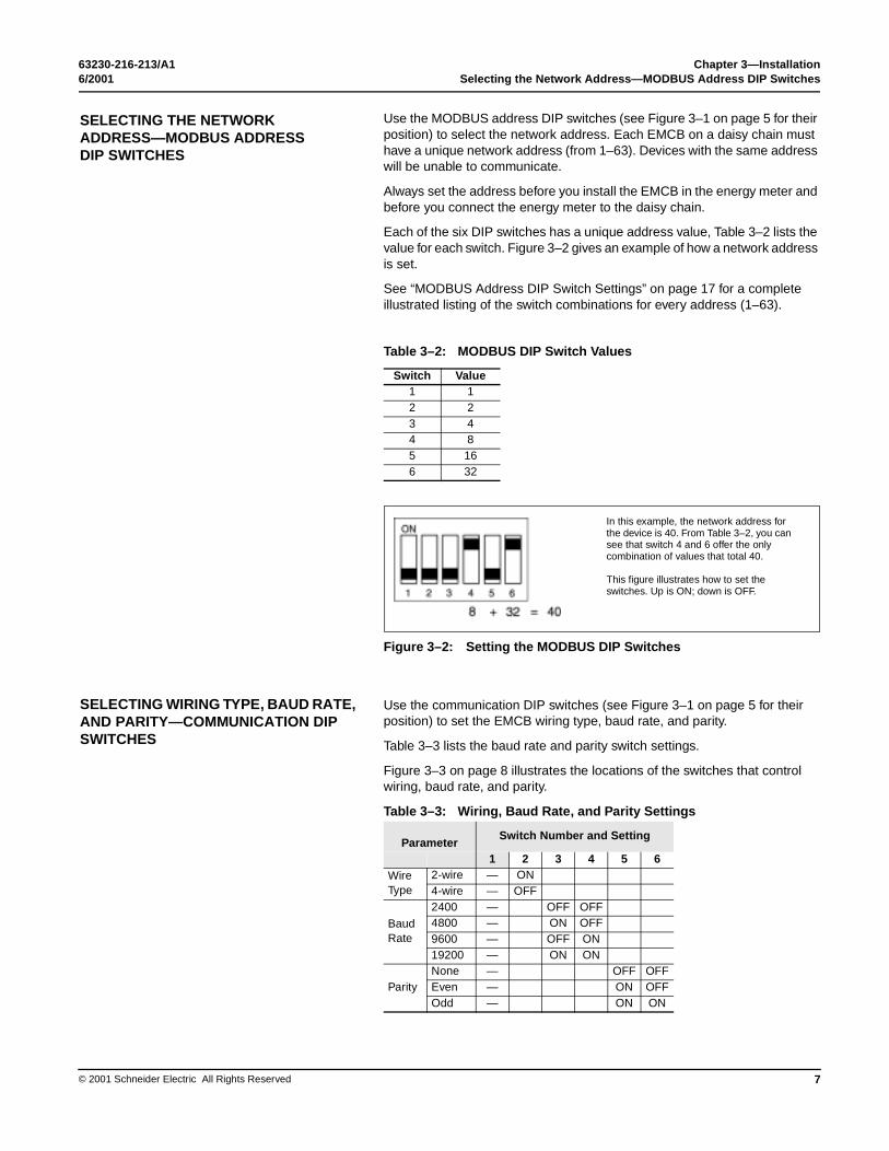
Each of the six DIP switches has a unique address value, Table 3–2 lists the value for each switch. Figure 3–2 gives an example of how a network address is set.
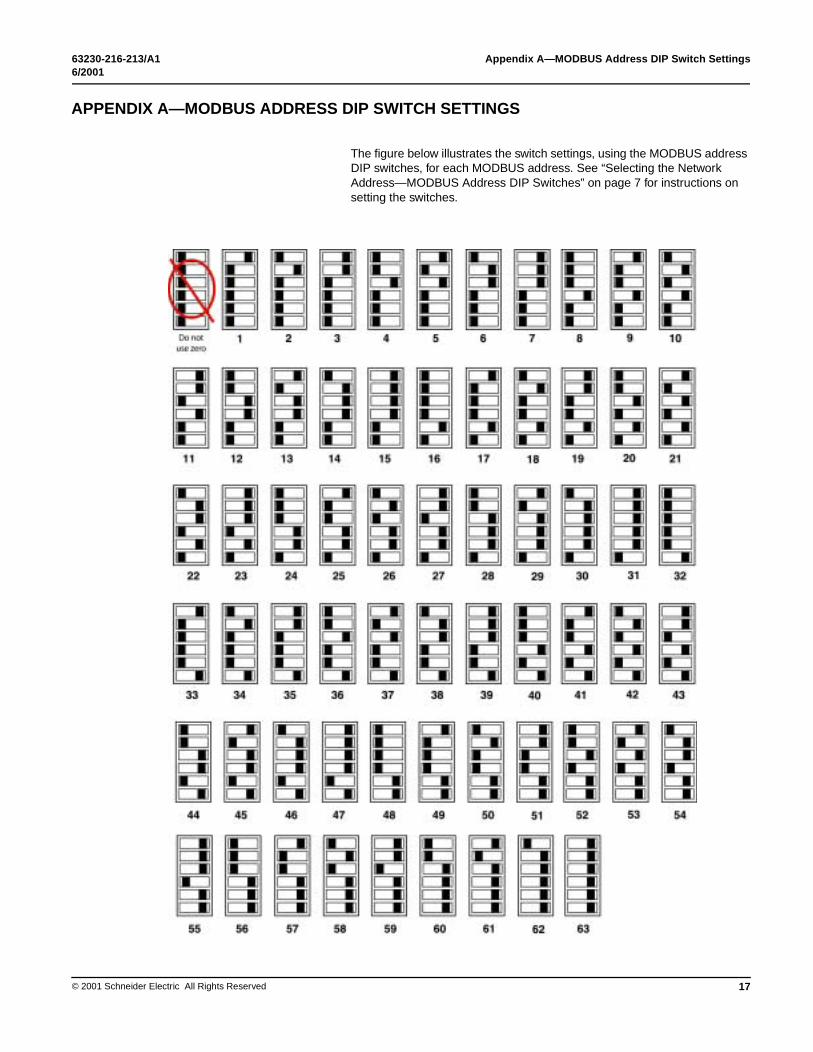
See “MODBUS Address DIP Switch Settings” on page 17 for a complete illustrated listing of the switch combinations for every address (1–63).
Figure 3–2: Setting the MODBUS DIP Switches
Use the communication DIP switches (see Figure 3–1 on page 5 for their position) to set the EMCB wiring type, baud rate, and parity.
Table 3–3 lists the baud rate and parity switch settings.
Figure 3–3 on page 8 illustrates the locations of the switches that control wiring, baud rate, and parity.
Table 3–3: Wiring, Baud Rate, and Parity Settings
Table 3–2: MODBUS DIP Switch Values
Switch Value1 12 23 44 85 166 32
ParameterSwitch Number and Setting
1 2 3 4 5 6Wire Type
2-wire — ON4-wire — OFF
Baud Rate
2400 — OFF OFF4800 — ON OFF9600 — OFF ON19200 — ON ON
ParityNone — OFF OFFEven — ON OFFOdd — ON ON
In this example, the network address for the device is 40. From Table 3–2, you can see that switch 4 and 6 offer the only combination of values that total 40.
This figure illustrates how to set the switches. Up is ON; down is OFF.
7

Chapter 3—Installation 63230-216-213/A1RS-485 communications 6/2001
8
RS-485 COMMUNICATIONS
Daisy Chain Maximum Distances
Figure 3–3: Setting the Communication DIP Switches
This section describes the procedures for wiring the communications connection and terminating the EMCB (if it is the last device in its daisy chain).
The maximum number of devices capable of being supported on a single daisy chain is determined based on the combination of baud rate, the length of the daisy chain, and the types of RS-485 devices (2-wire/4-wire) on the daisy chain. The RS-485 interface will support daisy chains that fall within the specifications shown in Tables 3–4 and 3–5.
Table 3–4: 4-Wire Daisy Chain Maximum Distances
Baud RateMaximum Distances
1–16 Devices 17–32 Devices
1200 10,000 ft. (3,048 m) 10,000 ft. (3,048 m)
2400 10,000 ft. (3,048 m) 5,000 ft. (1,524 m)
4800 10,000 ft. (3,048 m) 5,000 ft. (1,524 m)
9600 10,000 ft. (3,048 m) 4,000 ft. (1,219 m)
19200 5,000 ft. (1,524 m) 2,500 ft. (762 m)
38400 5,000 ft. (1,524 m) 1,500 ft. (457 m)
Table 3–5: 2-Wire Daisy Chain Maximum Distances
Baud RateMaximum Distances
1–8 Devices 9–16 Devices
1200 10,000 ft. (3,048 m) 10,000 ft. (3,048 m)
2400 10,000 ft. (3,048 m) 5,000 ft. (1,524 m)
4800 10,000 ft. (3,048 m) 5,000 ft. (1,524 m)
9600 10,000 ft. (3,048 m) 4,000 ft. (1,219 m)
19200 5,000 ft. (1,524 m) 2,500 ft. (762 m)
38400 2,500 ft. (762 m) 1,500 ft. (457 m)
Switch 1 is unused. Always leave it in the OFF position.
This example illustrates the default switch settings for a 2-wire device that uses 9600 baud rate no parity.
© 2001 Schneider Electric All Rights Reserved

63230-216-213/A1 Chapter 3—Installation6/2001 RS-485 communications
© 2001 Schneider Electric All Rights Reserved
Wiring the RS-485 Communications Connector
For this procedure, remove the connector from the RS-485 communication terminals of the EMCB (see Figure 3–1 on page 5). To wire RS-485 communications, follow these steps:
1. Wire the communications connector as shown in Figure 3–4 (2-wire communication) or Figure 3–5 (4-wire communication).NOTE: The Wire Type setting in the communication DIP switch must match this wiring type (see Table 3–3 for communication DIP switch settings).
Figure 3–4: 2-wire Communications Wiring
Energy Meter Communication Board
Detail showing MODBUS connector wired for 2-wire communication, not in a daisy chain
9

Chapter 3—Installation 63230-216-213/A1RS-485 communications 6/2001
10
Figure 3–5: 4-wire Communications Wiring
2. Use a small, flat-blade screwdriver to tighten the connector screws.3. Replace the connector on the RS-485 communication terminals of the
EMCB.4. If the EMCB is the last device on the daisy chain, terminate it, following
directions in “Terminating the EMCB”.
Energy Meter Communication Board
Detail showing MODBUS connector wired for 4-wire communication, not in a daisy chain
© 2001 Schneider Electric All Rights Reserved

63230-216-213/A1 Chapter 3—Installation6/2001 RS-485 communications
© 2001 Schneider Electric All Rights Reserved
Terminating the EMCB
If the EMCB is the last device in a daisy chain, you need to terminate it to ensure reliable communication. To terminate the EMCB, use a 3090MCTAS485 terminator. (If you did not order a terminator when you ordered your EMCB, you must order it separately.) Follow these instructions to terminate the EMCB:1. Insert the wires from the daisy chain into the terminals of the connector, following the instructions in “Wiring the RS-485 Communications Connector”.
2. Before tightening the connector screws, insert the wires of the terminator into the connector (see Figure 3–6).
Figure 3–6: Installing the 3090CTAS485 Terminator
3. Use a small, flat-blade screwdriver to tighten the connector screws.
daisy chainwires
terminator
11

Chapter 3—Installation 63230-216-213/A1Installing The EMCB 6/2001
12
INSTALLING THE EMCB
This section provides information on installing the EMCB in the energy meter.NOTE: Before you begin this procedure, first set the wiring, baud rate, and parity, using the communication DIP switches; and set the network address, using the MODBUS address DIIP switches.
The EMCB is designed as a plug-and play accessory for the POWERLOGIC energy meter. Follow these instructions to install the EMCB into the energy meter.
1. Turn off all power to the energy meter and the equipment in which it is installed. To turn off power to the energy meter, do this:
a. Remove the voltage terminal from the energy meter and all fuses.
b. Always use a properly rated voltage sensing device to confirm that power is off.
2. To discharge static, follow the instructions that come with your anti-static or grounding strap. NOTE: We recommend using an anti-static or grounding strap until you have completed installation of the EMCB.
HAZARD OF ELECTRIC SHOCK, BURN, OR EXPLOSION
• Remove the voltage terminal and all fuses from the energy meter.• Turn off all power to the energy meter and the equipment in which it
is installed. To turn off power to the energy meter, do this:
a. Remove the voltage terminal from the energy meter and all fuses.b. Always use a properly rated voltage sensing device to confirm
that power is off.
• Use a properly rated voltage sensing device to confirm that all power is off.
Failure to follow these instructions will result in death or serious injury.
DANGER
ESD-SENSITIVE COMPONENTS
Use an anti-static or grounding strap (customer-supplied) to ground yourself and discharge any static charge before installing the EMCB. Static can damage electrostatic discharge-sensitive components in the circuit monitor and its accessories.
Failure to follow this instruction can result in equipment damage.
CAUTION
© 2001 Schneider Electric All Rights Reserved

63230-216-213/A1 Chapter 3—Installation6/2001 Installing The EMCB
© 2001 Schneider Electric All Rights Reserved
3. Slide the EMCB into the grooves in the energy meter. (Figure 3–7) The sides of the EMCB slide down into the channels on either side of the energy meter. When the male connection to the energy meter clicks into place, the EMCB is properly installed.
Figure 3–7: Inserting the EMCB into the energy meter.
4. Insert the RS-485 connector onto the RS-485 communication terminals (Figure 3–1 on page 5).
5. If using the subinterval feature, wire into the “end of demand subinterval terminal.”
6. Replace the voltage terminal into the energy meter and all fuses.7. Verify that the green Alive LED is blinking on the board. If the LED is not
lit, see “Chapter 4—Troubleshooting” on page 15.
grooves
13

Chapter 3—Installation 63230-216-213/A1Installing The EMCB 6/2001
14
© 2001 Schneider Electric All Rights Reserved
63230-216-213/A1 Chapter 4—Troubleshooting6/2001
© 2001 Schneider Electric All Rights Reserved
CHAPTER 4—TROUBLESHOOTING
This section covers the solutions for some of the common problems you might encounter with the EMCB.
There are five LEDs that indicate various types of communication. Figure 4–1 indicates the locations of these LEDs. All LEDs will blink when operating normally.
If there is a problem communicating, first be sure that the board is properly seated in its slot on the energy meter. Verify that the sides of the EMCB are in the slots on the sides of the energy meter and that the connector has clicked into place in the connection slot of the energy meter.
HAZARD OF ELECTRIC SHOCK, BURN, OR EXPLOSION
• This equipment must be installed and serviced only by qualified personnel.
• Qualified persons performing diagnostics or troubleshooting that require electrical conductors to be energized must comply with NFPA 70 E - Standard for Electrical Safety Requirements for Employee Workplaces and OSHA Standards - 29 CFR Part 1910 Subpart S - Electrical.
Failure to observe this instruction will result in death or serious injury.
DANGER
15

Chapter 4—Troubleshooting 63230-216-213/A16/2001
16
Number LED Abnormal Operatio
1 RS-485 (TX) Not blinking
2 RS-485 (RX) Not blinking
RX is steadily lit
3 From main board (RX) Not blinking
4 From main board (TX) Not blinking, but “Alive” LED is blinkin
5 “Alive” status Steadily lit
� � �
See Table 4–1 for other communication problems and solutions.
Figure 4–1: LED positions on the EMCB
Table 4–1: EMCB LED Problems and Solutions
n Solution
There is no communication from the master. Check the wiring; TX+/TX– and RX+/RX– may be reversed. Correct the wiring.
If RX is blinking, verify the DIP switch address, parity, baud rate, and wire type.
There is no communication from the master. Check the wiring; TX+/TX– and RX+/RX– may be reversed. Correct the wiring.
The RX+ and RX– wires are reversed. Correct the wiring.
The main board is not responding. Contact your local representative for technical support.
gThere is an internal communications board error. Contact your local representative for technical support.
There is an internal communications board error. Contact your local representative for technical support.
© 2001 Schneider Electric All Rights Reserved
63230-216-213/A1 Appendix A—MODBUS Address DIP Switch Settings6/2001
© 2001 Schneider Electric All Rights Reserved
APPENDIX A—MODBUS ADDRESS
The figure below illustrates the switch settings, using the MODBUS address DIP switches, for each MODBUS address. See “Selecting the Network Address—MODBUS Address DIP Switches” on page 7 for instructions on setting the switches.
DIP SWITCH SETTINGS
17

Appendix A—MODBUS Address DIP Switch Settings 63230-216-213/A16/2001
18
© 2001 Schneider Electric All Rights Reserved
63230-216-213/A1 Index6/2001
© 2001 Schneider Electric All R
INDEX
AAlive LED 6, 16anti-static or grounding strap 12Bbaud rate
setting 7
Ccommunication
troubleshooting 15communication DIP switches
setting 7communications connector
wiring 9
Ddaisy chain
guidelines for setup 6maximum distances 8
DIP switchescommunication 7MODBUS address 7
Eelectrostatic discharge-sensitive components 12EMCB
components (table) 6description 5description/application 2illustration 1, 5installation 12specifications (table) 2termination 11
end of demand subinterval terminal 6, 13energy meter
turning off power to 12ESD. See electrostatic discharge-sensitive com-
ponents.
Ffigure
2-wire communications wiring 94-wire communications wiring 10bottom view of the EMCB, illustrating commu-
nication points 5energy meter communication card 1installing the 3090CTAS485 terminator 11setting the communication DIP switches 8setting the MODBUS DIP switches 7
Ggrounding strap, using during installation 12
Iinformation about POWERLOGIC 1installation
discharging static before 12instructions 12
LLED operation
L
MMM
Oo
Pp
RrR
Ss
ss
Tt
ttt
Www
ights Reserved
table 16EDs
descriptions 6positions on the EMCB
illustrated 16troubleshooting 15
ODBUS address DIP switches 7ODBUS RTU protocol 2
verview 1
aritysetting 7
elated documentation 1S-485 communications connector
wiring 9
afetyprecautions 3
etting the network address 6pecifications 2
able2-wire daisy chain maximum distances 84-wire daisy chain maximum distances 8EMCB LED problems and solutions 16EMCB specifications 2energy meter communication board compo-
nents 6MODBUS DIP switch values 7wiring, baud rate, and parity settings 7
erminating the EMCB 11roubleshooting 15rue kW demand information 2
iring the RS-485 connector 9iring type
setting 7
19

Index 63230-216-213/A16/2001
20
© 2001 Schneider Electric All Rights Reserved