powerlogic power-monitoring units iem3000 series2 version: 1.0 plsed310047en.indd energy meter...
TRANSCRIPT

iEM3000 Series
PowerLogic power-monitoring units
Technical data sheet

version: 1.0 PLSED310047EN.indd2
Energy Meter Series iEM3000Functions and characteristics
Kilowatt-hour metersP
B10
8410
The PowerLogic Energy meter Series iEM3000 offers a cost-attractive, competitive range of DIN rail-mounted energy meters ideal for sub-billing and cost allocation applications.
Combined with communication systems, like Smart Link, the iEM3000 series make it easy to integrate electrical distribution measurements into customer’s facility management systems. It’s the right energy meter at the right price for the right job.
Two versions are available: 63A direct measure (iEM3100) and current transformers associated meter (iEM3200). For each range five versions are available to satisfy from basic to advanced applications:b iEM3100/iEM3200: kWh meter with partial counterb iEM3110/iEM3210: kWh meter with partial counter and pulse output. MID certified.b iEM3115/iEM3215: a multi-tariff meter controlled by digital input or internal clock, MID certified.b iEM3150/iEM3250: kWh meter with partial counter and current, voltage, power measurement. Modbus communication.b iEM3155/iEM3255: energy meter, four quadrant, multi-tariffs with partial counter and current, voltage, power measurement. Modbus communication, digital input/output and MID certified.
Innovative design makes the meters smart and simple:b Easy to install for panel buildersb Easy to commission for contractors and installersb Easy to operate for end users
Applications Cost management applications b�Bill verificationb�Sub-billing, including WAGES viewb�Cost allocation, including WAGES view
Network management applicationsb�Basic electrical parameters like current, voltage and powerb Onboard overload alarm to avoid circuit overload and tripb Easy integration with PLC systems by input/output interface
Market segmentsb�Buildings & Industryb�Data centres and networksb�Infrastructure (airports, road tunnels, telecom)
Characteristicsb�Self-powered metersb�Chain measurement (meters + CTs) accuracy class 1 b�Compliance with IEC 61557-12, IEC 62053-21/22, IEC 62053-23, EN50470-3b�Graphical display for easy viewingb�Easy wiring (without CTs) iEM3100 seriesb�Double fixation on DIN rail (horizontal or vertical)b�Anti-tamper security features ensure the integrity of your data
Part numbers
Energy Meter Series iEM3100
PB
1084
32
Energy Meter Series iEM3255
Front of meter parts1 Configuration mode2 Values and parameters3 Unit4 Cancellation5 Confirmation6 Selection7 Date and time8 Tariff currently used (iEM3255)9 Functions/Measurements
Meter model and description Current measurement Part no.
iEM3100 basic energy meter Direct connected 63 A A9MEM3100iEM3110 energy meter with pulse output Direct connected 63 A A9MEM3110iEM3115 multi-tariff energy meter Direct connected 63 A A9MEM3115iEM3150 energy meter & electrical parameter plus RS485 comm port
Direct connected 63 A A9MEM3150
iEM3155 advanced multi-tariff energy meter & electrical parameter plus RS485 comm port
Direct connected 63 A A9MEM3155
iEM3200 basic energy meter Transformer connected 6 A A9MEM3200iEM3210 energy meter with pulse output Transformer connected 6 A A9MEM3210iEM3215 multi-tariff energy meter Transformer connected 6 A A9MEM3215iEM3250 energy meter & electrical parameter plus RS485 comm port
Transformer connected 6 A A9MEM3250
iEM3255 advanced multi-tariff energy meter & electrical parameter plus RS485 comm port
Transformer connected 6 A A9MEM3255
version: 1.0 PLSED310047EN.indd 3
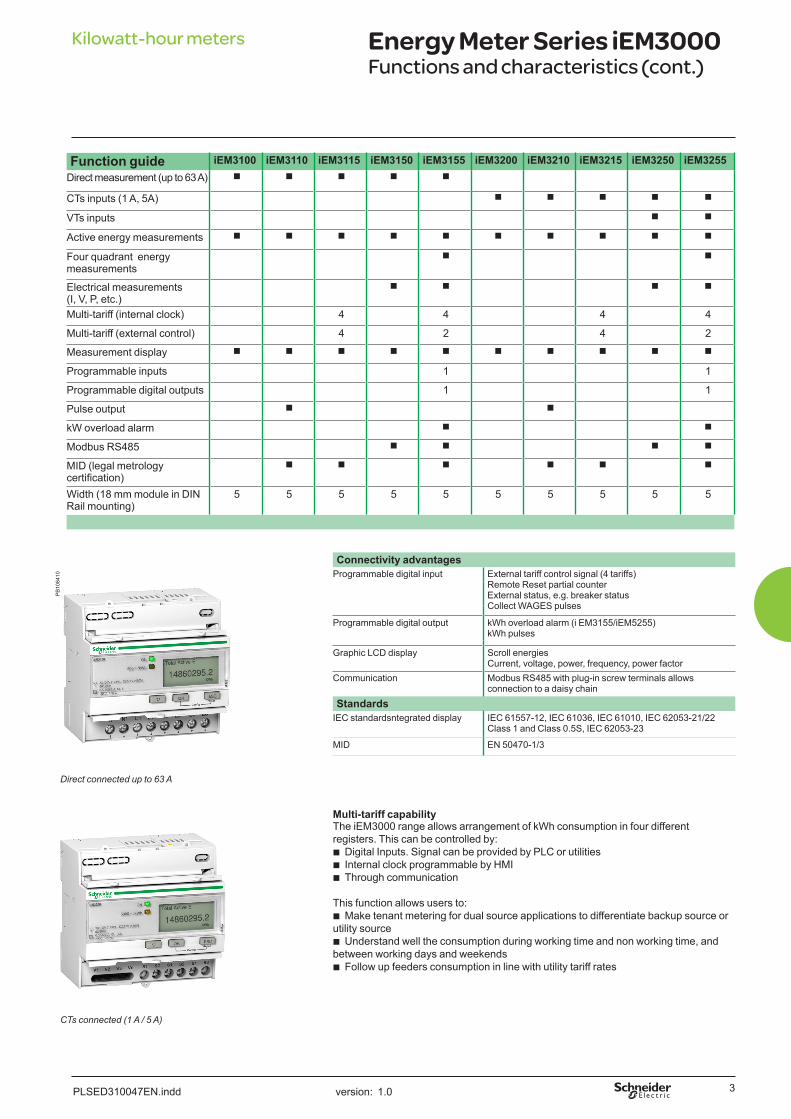
Kilowatt-hour meters Energy Meter Series iEM3000Functions and characteristics (cont.)
Function guide iEM3100 iEM3110 iEM3115 iEM3150 iEM3155 iEM3200 iEM3210 iEM3215 iEM3250 iEM3255Direct measurement (up to 63 A) b b b b b
CTs inputs (1 A, 5A) b b b b b
VTs inputs b b
Active energy measurements b b b b b b b b b b
Four quadrant energy measurements
b b
Electrical measurements (I, V, P, etc.)
b b b b
Multi-tariff (internal clock) 4 4 4 4
Multi-tariff (external control) 4 2 4 2
Measurement display b b b b b b b b b b
Programmable inputs 1 1
Programmable digital outputs 1 1
Pulse output b b
kW overload alarm b b
Modbus RS485 b b b b
MID (legal metrology certification)
b b b b b b
Width (18 mm module in DIN Rail mounting)
5 5 5 5 5 5 5 5 5 5
PB
1084
10
Connectivity advantagesProgrammable digital input External tariff control signal (4 tariffs)
Remote Reset partial counterExternal status, e.g. breaker status Collect WAGES pulses
Programmable digital output kWh overload alarm (i EM3155/iEM5255) kWh pulses
Graphic LCD display Scroll energiesCurrent, voltage, power, frequency, power factor
Communication Modbus RS485 with plug-in screw terminals allows connection to a daisy chain
StandardsIEC standardsntegrated display IEC 61557-12, IEC 61036, IEC 61010, IEC 62053-21/22
Class 1 and Class 0.5S, IEC 62053-23
MID EN 50470-1/3
Direct connected up to 63 A
Multi-tariff capabilityThe iEM3000 range allows arrangement of kWh consumption in four different registers. This can be controlled by:b Digital Inputs. Signal can be provided by PLC or utilitiesb Internal clock programmable by HMIb Through communication
This function allows users to:b Make tenant metering for dual source applications to differentiate backup source or utility sourceb Understand well the consumption during working time and non working time, and between working days and weekends b Follow up feeders consumption in line with utility tariff rates
CTs connected (1 A / 5 A)

version: 1.0 PLSED310047EN.indd
Energy Meter Series iEM3000Functions and characteristics (cont.)
Kilowatt-hour meters
4
Specification guide iEM3100 RangeiEM3100 iEM3110 iEM3115 iEM3150 iEM3155
Current (max.) Direct connected 63 A
Meter constant LED 500/kWh
Pulse output Up to 1000p/kWh
Up to 1000p/kWh
Multi-tariff 4 tariffs 4 tariffsCommunication Modbus via
RS485Modbus via
RS485DI/DO 0/1 2/0 1/1MID (EN50470-3) b b b
Network 1P+N, 3P, 3P+NAccuracy class Class 1 (IEC 62053-21 and IEC61557-12) Class B (EN50470-3)Wiring capacity 16 mm²
Display max. LCD 99999999.9kWhVoltage (L-L) 3 x 100/173 Vac to 3 x 277/480 Vac (50/60 Hz)IP protection IP40 front panel and IP20 casingTemperature -25°C to 55°C (K55)Product size 10 steps of 9mmOvervoltage and measurement Category III, Degree of pollution 2
kWh b b b b b
kVARh b
Active power b b
Reactive power b
Currents and voltages b b
Overload alarm b
Hour counter b
Specification guide iEM3200 RangeiEM3200 iEM3210 iEM3215 iEM3250 iEM3255
1 A / 5 A CTs (max current) 6 AMeter constant LED 5000/kWhPulse output frequency Up to 100p/kWh Up to 100p/kWhMulti-tariff 4 tariffs 4 tariffsCommunication Modbus via
RS485Modbus via
RS485DI/DO 0/1 2/0 1/1MID (EN50470-3) b b b
Network 1P+N, 3P, 3P+N support CTs
1P+N, 3P, 3P+N support CTs & VTs
Accuracy class Class 0.5S (IEC 62053-22 and IEC61557-12) Class C (EN50470-3)(1)
Wiring capacity 6 mm² for currents and 4 mm² for voltages
Display max. LCD 99999999.9kWh or 99999999.9MWhVoltage (L-L) 3 x 100/173 Vac to 3 x 277/480 Vac (50/60 Hz)IP protection IP40 front panel and IP20 casingTemperature -25°C to 55°C (K55)Product size 10 steps of 9mmOvervoltage & measurement Category III, Degree of pollution 2
kWh b b b b b
kVARh b
Active power b b
Reactive power b
Currents and voltages b b
Overload alarm b
Hour counter b
(1) For 1 A CTs Class 1 (IEC6253-21 and IEC61557-12 Class B (EN50470-3)

version: 1.0 PLSED310048EN.indd
Energy Meter Series iEM3000Installation and connection
Kilowatt-hour meters
iEM3000 series dimensions
PB
1053
02
PB
1053
03
iEM3000 series front flaps open and closed
PB
1053
05
PB
1053
06
iEM3x50 and iEM3x55 Comm./terminal parts1. Digital inputs for tariff control (iEM3255 / iEM3255)2. Digital output (iEM3255)3. Communication port4. Yellow indicator for communication diagnosis5. Display for measurement and configuration6. Cancellation7. Confirmtion8. Selection9 Flashing yellow meter indicator to check accuracy10 Green indicator: on/off, error
Note: These are sample wiring diagrams only. For further information please see the Installation Guide and User Guide documents for these products.
iEM3000 series parts1. Digital inputs for tariff control (iEM3115 / iEM3215)2. Display for measurement and configuration3. Pulse out for remote transfer (iEM3110 / iEM3210)4. Cancellation5. Confirmation6. Selection7. Flashing yellow meter indicator to check accuracy8. Green indicator: on/off, error
Pulse Output and Digital Input sample wiring diagrams
PB
1053
08P
B10
5301
5

version: 1.0 PLSED310048EN.indd
Energy Meter Series iEM3000 Installation and connection (cont.)
Kilowatt-hour meters
Note: These are sample wiring diagrams only. For further information please see the Installation Guide and User Guide documents for these products.
Modbus communications wiring diagram
PB
1084
41
iEM31xx series sample wiring diagrams - 1 and 3 phase
(1) - Single phase wiring supported only by iEM3150 and iEM3155. - Neutral (N’) must not be connected to avoid possible damage to the meter.
PB
1053
10
PB
1053
11
iEM32xx series sample wiring diagrams -1 phase Protection (to be adapted to suit the short-circuit current at the connection point)
Shorting switch unit
Note: These are sample wiring diagrams only. For further information please see the Installation Guide and User Guide documents for these products.
PB
1053
25
1PH2W L-N
1PH2W L-L
1PH3W L-L-N
1PH4W(1)
3PH3W
3PH4W
6

version: 1.0 PLSED310048EN.indd
Energy Meter Series iEM3000 Installation and connection (cont.)
Kilowatt-hour meters
iEM32xx Series sample wiring diagrams - 3 phase without VTs
iEM32xx Series sample wiring diagrams - 3 phase with VTs (iEM3250 & iEM3255) Note: These are sample diagrams only. For further information please see the Installation Guide and User Guide documents for these products.
Protection (to be adapted to suit the short-circuit current at the connection point)
Shorting switch unit
7

AR
T 96
0661
/ ©
201
2 -
Sch
neid
er E
lect
ric -
All
right
s re
serv
ed
Schneider Electric Industries SAS
35, Rue Joseph Monier,
CS 30323
F - 92506 Rueil Malmaison Cedex
RCS Nanterre 954 503 439
Capital social 896 313 776
www.schneider-electric.com
PLSED310049EN
As standards, specifications and designs develop from time to time, please
ask for confirmation of the information given in this document.
This document has been printed on recycled paper
Design: Schneider Electric
Photos: Schneider Electric
Printing: Altavia Connexion - Made in France
April 2012
10-31-1247