instruction manual bedienungsanleitung … must be operated with caution and common sense and...
TRANSCRIPT
Before operating this vehicle, please read all printed materials thoroughly.Horizon Hobby is not responsible for inadvertent errors in this manual.
INSTRUCTION MANUALBEDIENUNGSANLEITUNGMANUEL D’UTILISATIONMANUALE DI ISTRUZIONI

EN
2 TENACITY-T RTR, AVC: 1:10 4WD TRUGGY • INSTRUCTION MANUAL
Age Recommendation: Not for children under 14 years. This is not a toy.
WARNING: Read the ENTIRE instruction manual to become familiar with the features of the product before operating. Failure to operate the product correctly can result in dam-age to the product, personal property and cause serious injury.
This is a sophisticated hobby product. It must be operated with caution and common sense and requires some basic mechanical ability. Failure to operate this Product in a safe and responsible manner could result in injury or damage to the product or other property. This product is not intended for use by children without direct adult supervision. Do not use with incompatible components or alter this product in any way outside of the instructions provided by Horizon Hobby, LLC. This manual contains instructions for safety, operation and mainte-nance. It is essential to read and follow all the instructions and warnings in the manual, prior to assembly, setup or use, in order to operate correctly and avoid damage or serious injury.
WARNING AGAINST COUNTERFEIT PRODUCTS Always purchase from a Horizon Hobby, LLC authorized dealer to ensure authentic high-quality Spektrum product. Horizon Hobby, LLC disclaims all support and warranty with regards, but not limited to, compatibility and performance of counterfeit products
or products claiming compatibility with DSM or Spektrum technology.
NOTICEAll instructions, warranties and other collateral documents are subject to change at the sole discretion of Horizon Hobby, LLC. For up-to-date product literature, visit horizonhobby.com and click on the support tab for this product.
MEANING OF SPECIAL LANGUAGEThe following terms are used throughout the product literature to indicate various levels of potential harm when operating this product:
WARNING: Procedures, which if not properly followed, create the probability of property damage, collateral damage, and serious injury OR create a high probability of superfi cial injury.
CAUTION: Procedures, which if not properly followed, create the probability of physical property damage AND a possibility of serious injury.
NOTICE: Procedures, which if not properly followed, create a possibility of physical property damage AND a little or no possibility of injury.
REGISTER YOUR LOSI PRODUCT ONLINE Register your vehicle now and be the fi rst to fi nd out about the latest option parts, product updates and more. Click on the Support tab at WWW.LOSI.COM and follow the product registration link to stay connected.
As the user of this product, you are solely responsible for operating in a manner that does not endanger yourself and others or result in damage to the product or property of others. This model is controlled by a radio signal subject to interference from many sources outside your control. This interference can cause momentary loss of control, so it is advisable to always keep a safe distance in all directions around your model as this margin will help avoid collisions or injury.
• Never operate your model with low transmitter batteries.• Always operate your model in open spaces away from full-size vehicles, traffic and people.• Never operate the model in the street or in populated areas for any reason.• Carefully follow the directions and warnings for this and any optional support equipment
(chargers, rechargeable battery packs, etc.) you use.• Keep all chemicals, small parts and anything electrical out of the reach of children.
• Never lick or place any portion of the model in your mouth as it could cause serious injury or even death.
• Exercise caution when using tools and sharp instruments.• Take care during maintenance as some parts may have sharp edges.• Immediately after using your model, do NOT touch equipment such as the motor, electronic
speed control and battery, because they generate high temperatures. You may burn yourself seriously touching them.
• Do not put fi ngers or any objects inside rotating and moving parts, as this may cause damage or serious injury.
• Always turn on your transmitter before you turn on the receiver in the car. Always turn off the receiver before turning your transmitter off.
• Keep the wheels of the model off the ground when checking the operation of the radio equipment.
SAFETY PRECAUTIONS AND WARNINGS
TABLE OF CONTENTSREGISTER YOUR LOSI PRODUCT ONLINE .................................................................2BOX CONTENTS ........................................................................................................3
COMPONENTS .................................................................................................................3WATER-RESISTANT VEHICLE WITH WATERPROOF ELECTRONICS ..............................3
GENERAL PRECAUTIONS ...................................................................................................3WET CONDITIONS MAINTENANCE ....................................................................................3
QUICK START ............................................................................................................3CHARGING THE BATTERY .........................................................................................3COMPONENTS ..........................................................................................................3INSTALLING THE BATTERY ........................................................................................4SPEKTRUM DX2E ACTIVE RADIO SYSTEM ................................................................4
INSTALLING THE TRANSMITTER BATTERIES ........................................................................4SRS6000 AVC TECHNOLOGY RECEIVER ....................................................................4
AUX CHANNELS ................................................................................................................4BINDING AND CALIBRATING THE RECEIVER .....................................................................5DISABLING THE STABILITY ASSIST FUNCTION ....................................................................5
DRIVING PRECAUTIONS ..........................................................................................5POWERING ON THE VEHICLE ....................................................................................5BEFORE RUNNING YOUR VEHICLE ............................................................................5AVC® SENSITIVITY ..................................................................................................5RUN TIME .................................................................................................................6
TO IMPROVE RUN TIMES ...................................................................................................6PERFORMING A CONTROL DIRECTION TEST.............................................................6
CHANGING THE TRAVEL ADJUST SETTINGS .............................................................6DYNAMITE® FUZE™ 130A SENSORLESS BRUSHLESS ESC (DYN4955) ....................6
SPECIFICATIONS ...............................................................................................................6ESC LED STATUS ...............................................................................................................6AUDIBLE WARNING TONES ...............................................................................................6ESC CALIBRATION PROCEDURE ........................................................................................6ESC FUNCTIONS AND MODES ...........................................................................................7ESC PROGRAMMING PROCEDURE ....................................................................................7DESCRIPTIONS ..................................................................................................................7
DYNAMITE® FUZE™ 3800KV BRUSHLESS MOTOR (DYNS1616) ..............................8PRECAUTIONS ..................................................................................................................8GEARING .........................................................................................................................8CHANGING THE PINION GEAR/GEAR RATIO ......................................................................8SETTING THE GEAR MESH .................................................................................................8
TROUBLESHOOTING GUIDE ......................................................................................8LIMITED WARRANTY ...............................................................................................8WARRANTY AND SERVICE CONTACT INFORMATION ................................................9FCC STATEMENT .......................................................................................................9IC INFORMATION .....................................................................................................9COMPLIANCE INFORMATION FOR THE EUROPEAN UNION ......................................9REPLACEMENT PARTS ............................................................................................10OPTIONAL PARTS ...................................................................................................11EXPLODED VIEW ....................................................................................................12

3
EN
TENACITY-T RTR, AVC: 1:10 4WD TRUGGY • INSTRUCTION MANUAL
BOX CONTENTS
Your new Horizon Hobby vehicle has been designed and built with a combination of waterproof and water-resistant components to allow you to operate the product in many “wet conditions,” including puddles, creeks, wet grass, snow and even rain.
While the entire vehicle is highly water-resistant, it is not completely waterproof and your vehicle should NOT be treated like a submarine. The various electronic components used in the vehicle, such as the Electronic Speed Control (ESC), servo(s) and receiver are waterproof, how-ever, most of the mechanical components are water-resistant and should not be submerged.
Metal parts, including the bearings, hinge pins, screws and nuts, as well as the contacts in the electrical cables, will be susceptible to corrosion if additional maintenance is not performed after running in wet conditions. To maximize the long-term performance of your vehicle and to keep the warranty intact, the procedures described in the “Wet Conditions Maintenance” section below must be performed regularly if you choose to run in wet conditions. If you are not willing to perform the additional care and maintenance required, then you should not operate the vehicle in those conditions.
CAUTION: Failure to exercise caution while using this product and complying with the following precautions could result in product malfunction and/or void the warranty.
GENERAL PRECAUTIONS• Read through the wet conditions maintenance procedures and make sure that you
have all the tools you will need to properly maintain your vehicle.• Not all batteries can be used in wet conditions. Consult the battery manufacturer before
use. Caution should be taken when using Li-Po batteries in wet conditions.• Most transmitters are not water-resistant. Consult your transmitter’s manual or the
manufacturer before operation.• Never operate your transmitter or vehicle where lightning may be present.• Do not operate your vehicle where it could come in contact with salt water (ocean
water or water on salt-covered roads), contaminated or polluted water. Salt water is very conductive and highly corrosive, so use caution.
• Even minimal water contact can reduce the life of your motor if it has not been certifi ed as water-resistant or waterproof. If the motor becomes excessively wet, apply very light throttle until the water is mostly removed from the motor. Running a wet motor at high speeds may rapidly damage the motor.
• Driving in wet conditions can reduce the life of the motor. The additional resistance of operating in water causes excess strain. Alter the gear ratio by using a smaller pinion or larger spur gear. This will increase torque (and motor life) when running in mud, deeper puddles, or any wet conditions that will increase the load on the motor for an extended period of time.
WET CONDITIONS MAINTENANCE• Drain any water that has collected in the tires by spinning them at high speed. With the
body removed, place the vehicle upside down and pull full throttle for a few short bursts until the water has been removed.
CAUTION: Always keep hands, fi ngers, tools and any loose or hanging objects away from rotating parts when performing the above drying technique.
• Remove the battery pack(s) and dry the contacts. If you have an air compressor or a can of compressed air, blow out any water that may be inside the recessed connector housing.
• Remove the tires/wheels from the vehicle and gently rinse the mud and dirt off with a garden hose. Avoid rinsing the bearings and transmission.
NOTICE: Never use a pressure washer to clean your vehicle.
• Use an air compressor or a can of compressed air to dry the vehicle and help remove any water that may have gotten into small crevices or corners.
• Spray the bearings, drive train, fasteners and other metal parts with a water-displacing light oil. Do not spray the motor.
• Let the vehicle air dry before you store it. Water (and oil) may continue to drip for a few hours.• Increase the frequency of disassembly, inspection and lubrication of the following:
- Front and rear axle hub assembly bearings. - All transmission cases, gears and differentials. - Motor—clean with an aerosol motor cleaner and re-oil the bushings with lightweight motor oil.
WATER-RESISTANT VEHICLE WITH WATERPROOF ELECTRONICS
QUICK STARTPlease read the entire manual to gain a full understanding of the TENACITY RTR vehicle, fi ne-tuning the setup and performing maintenance.
1. Read the safety precautions found in this manual.2. Charge a battery for the vehicle. Refer to the included charging warnings and
instructions for battery charging information.3. Install the AA batteries in the transmitter. Only use alkaline
or rechargeable batteries.4. Install the fully charged battery in the vehicle.
5. Power ON the transmitter and then the vehicle. Wait 5 seconds for the ESC to initialize. Always power the transmitter ON before the vehicle and power it OFF after the vehicle has been powered OFF.
6. Check the steering and throttle control directions. Verify that the servos are moving in the correct direction.
7. Drive your vehicle.8. Perform any necessary maintenance.
CHARGING THE BATTERY
COMPONENTS• Losi® TENACITY™-T RTR, AVC®: 1/10-Scale 4WD Truggy (LOS03011T1/T2)• Spektrum™ DX2E Active™, 2.4GHz Transmitter (SPM2335)• Spektrum™ 6-Channel DSMR® AVC Surface Receiver (SPMSRS6000)• Spektrum™ 9KG 23T Waterproof Servo (SPMS605)• Dynamite® Fuze™ 130A Sensorless Brushless Waterproof ESC (DYN4955)• Dynamite® Fuze™ 550 Brushless Motor 3800Kv (DYNS1616)• 4 AA batteries (for transmitter)
Choose a battery designed to work with the Dynamite® Fuze™ 130A Sensorless BL Waterproof ESC. We recommend the Dynamite® 7.4 5000mAh 2S 30C LiPo: Hardcase with EC3™ connector (DYN9005EC) or Dynamite 11.1 5000mAh 3S 30C LiPo Hardcase with EC3 connector (DYN9007EC). Choose a charger designed to charge 2S and/or 3S Li-Po batteries.
We recommend the Dynamite® Prophet™ Sport Li-Po 35W AC Battery Charger (DYNC2005CA). Refer to your battery and charger manuals for usage, safety, and charging information.
IMPORTANT: When using a 3S battery, you must change the motor pinion gear to the 12T pinion provided with your vehicle.

EN
4 TENACITY-T RTR, AVC: 1:10 4WD TRUGGY • INSTRUCTION MANUAL
12
3
4
56
78 10 119 12 13
INSTALLING THE BATTERY
INSTALLING THE TRANSMITTER BATTERIES1. Push in the battery cover a small amount to release the retaining tab, then remove the cover.2. Install 4 AA batteries, taking care to align the battery polarity to the diagram in the
transmitter’s battery case.3. Carefully reinstall the battery cover by aligning the tabs with the slots on the transmitter.
CAUTION: If using rechargeable batteries, charge only rechargeable batteries. Charging non-rechargeable batteries may cause the batteries to burst, resulting in
injury to persons and/or damage to property.
CAUTION: Risk of explosion if battery is replaced by an incorrect type. Dispose of used batteries according to national regulations.
For more information on the transmitter, go to www.horizonhobby.com and click on the support tab for the Spektrum DX2E to download the instruction manual.
SRS6000 AVC TECHNOLOGY RECEIVERAntenna
Bind/Battery
Aux 4/Disable
Aux 3
Aux 2
Aux 1
Throttle
Steering
AUX CHANNELSThe Aux channels can operate as additional servo channels, or as a power supply for a personal transponder.
If AVC is active, only 4 channels; Steering, Throttle, AUX3 and AUX4 are operational. The reaming Aux channels can be used to power a personal transponder or lights.
If AVC is disabled (see DISABLING THE STABILITY ASSIST FUNCTION), all 6 channels including the Aux channels can operate as servo channels.
SPEKTRUM DX2E ACTIVE RADIO SYSTEM
1. Ensure the ESC is powered OFF.2. Rotate the battery hatch lock to align the fl at section with the edge of the battery hatch.3. Open the battery hatch.4. Connect the battery to the ESC noting the correct polarity.
5. Install the fully charged battery in the vehicle.6. Close the battery hatch and rotate the lock fully to secure the hatch.7. Power ON the transmitter, then the vehicle.IMPORTANT: Secure the ESC wires so they do not interfere with the gearing.
1. Steering Wheel Controls direction (left/right) of the model2. Throttle Trigger Controls speed and direction (forward/brake/reverse) of the model3. BIND Button Puts the transmitter into Bind Mode4. ON/OFF Switch Turns the power ON/OFF for the transmitter5. TH.REV Reverses function of the speed control when pulled back or pushed forward6. Indicator Lights
- Solid green light—indicates adequate battery power - Flashing green light—indicates the battery voltage is critically low. Replace batteries
7. ST. REV Reverses the function of the steering when the wheels is turned left or right8. ST Trim Adjusts the steering center point9. TH Trim Adjusts the throttle neutral point10. TH Limiter Limits throttle output to 50, 70 or 100%.11. 3-Position Switch Used to control a third channel and is preset at -100%/Neutral/100%12. ST Rate Adjusts the sensitivity of AVC technology13. Antenna Transmits the signal to the model
5
EN
TENACITY-T RTR, AVC: 1:10 4WD TRUGGY • INSTRUCTION MANUAL
DRIVING PRECAUTIONS • Maintain sight of the vehicle at all times.
• Routinely inspect the vehicle for loose wheel hardware.
• Routinely inspect the steering assembly for any loose hardware. Driving the vehicle off-road can cause fasteners to loosen over time.
• Do not drive the vehicle in tall grass. Doing so can damage the vehicle or electronics.
• Stop driving the vehicle when you notice a lack of power. Driving the vehicle when the battery is discharged can cause the receiver to power off. If the receiver loses power, you will lose control of the vehicle. Damage due to an over-discharged Li-Po battery is not covered under warranty.
CAUTION: Do not discharge a Li-Po battery below 3V per cell. Batteries discharged to a voltage lower than the lowest approved voltage may become damaged, result-
ing in loss of performance and potential fi re when batteries are charged.
• Do not apply forward or reverse throttle if the vehicle is stuck. Applying throttle in this instance can damage the motor or ESC.
• After driving the vehicle, allow the electronics to cool before driving the vehicle again.
IMPORTANT: Keep wires away from all moving parts.
POWERING ON THE VEHICLE1. Center the ST TRIM and TH TRIM dials on the transmitter.
2. Power on the transmitter.
3. Install a fully charged battery pack per the Installing the Battery section.
4. Power on the ESC.
IMPORTANT: The vehicle MUST remain on a fl at, level surface and motionlessfor at least 5 seconds.
BEFORE RUNNING YOUR VEHICLE1. Check for free suspension movement. All suspension arms and steering components should
move freely. Any binds will cause the vehicle to handle poorly.
Tip: To increase the ride height and ground clearance of your vehicle, install the included shock spacers.
2. Charge a battery pack. Always charge the battery pack as per the battery and/or charger manufacturers’ instructions.
3. Set the transmitter steering trim. Follow the instructions to set the steering trim/subtrim so that the vehicle drives straight with no input to the steering.
4. Perform a Control Direction Test.
AVC® SENSITIVITYThe ST RATE dial adjusts the sensitivity, or stability, value in the receiver. If you increase the sensitivity, the AVC® system becomes more sensitive to the vehicle drifting left or right. You would use maximum sensitivity during high speed driving or drag racing, when you want the vehicle to stay in a straight line.
Turn the ST RATE knob counter-clockwise to reduce the sensitivity.
Turn the ST RATE knob clockwise to increase the sensitivity.
IMPORTANT: The ST RATE knob will only adjust the sensitivity when the transmitter is bound to a DSMR® receiver. When the transmitter is bound to a DSM®, DSM2® or DSM Marine receiver, the ST RATE knob controls the steering dual rate.
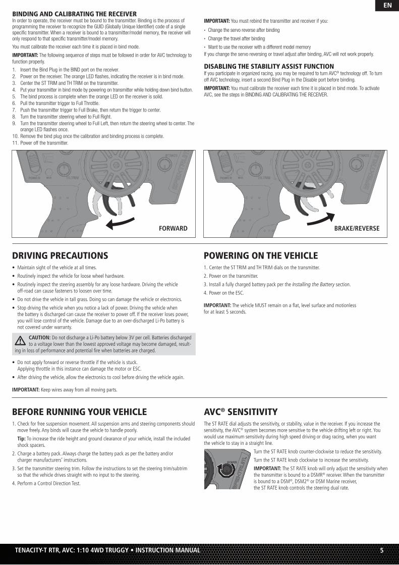
FORWARD BRAKE/REVERSE
BINDING AND CALIBRATING THE RECEIVER In order to operate, the receiver must be bound to the transmitter. Binding is the process of programming the receiver to recognize the GUID (Globally Unique Identifi er) code of a single specifi c transmitter. When a receiver is bound to a transmitter/model memory, the receiver will only respond to that specifi c transmitter/model memory.
You must calibrate the receiver each time it is placed in bind mode.
IMPORTANT: The following sequence of steps must be followed in order for AVC technology to
function properly.
1. Insert the Bind Plug in the BIND port on the receiver.
2. Power on the receiver. The orange LED fl ashes, indicating the receiver is in bind mode.
3. Center the ST TRIM and TH TRIM on the transmitter.
4. Put your transmitter in bind mode by powering on transmitter while holding down bind button.
5. The bind process is complete when the orange LED on the receiver is solid.
6. Pull the transmitter trigger to Full Throttle.
7. Push the transmitter trigger to Full Brake, then return the trigger to center.
8. Turn the transmitter steering wheel to Full Right.
9. Turn the transmitter steering wheel to Full Left, then return the steering wheel to center. The orange LED fl ashes once.
10. Remove the bind plug once the calibration and binding process is complete.
11. Power off the transmitter.
IMPORTANT: You must rebind the transmitter and receiver if you:
• Change the servo reverse after binding
• Change the travel after binding
• Want to use the receiver with a different model memory
If you change the servo reversing or travel adjust after binding, AVC will not work properly.
DISABLING THE STABILITY ASSIST FUNCTIONIf you participate in organized racing, you may be required to turn AVC® technology off. To turn
off AVC technology, insert a second Bind Plug in the Disable port before binding.
IMPORTANT: You must calibrate the receiver each time it is placed in bind mode. To activate
AVC, see the steps in BINDING AND CALIBRATING THE RECEIVER.
EN
6 TENACITY-T RTR, AVC: 1:10 4WD TRUGGY • INSTRUCTION MANUAL
EN
RUN TIMEThe largest factor in run time is the capacity of the battery pack. A larger mAh rating increases the amount of run time experienced.
The condition of a battery pack is also an important factor in both run time and speed. The battery connectors may become hot during driving. Batteries will lose performance and capacity over time.
Driving the vehicle from a stop to full speed repeatedly will damage the batteries and electronics over time. Sudden acceleration will also lead to shorter run times.
TO IMPROVE RUN TIMES• Keep your vehicle clean and well maintained.• Allow more airfl ow to the ESC and motor.• Change the gearing to a lower ratio. A lower ratio decreases the operating temperature
of the electronics. Use a smaller pinion gear or larger spur gear to lower the gear ratio.• Use a battery pack with a higher mAh rating.• Use the optimum charger to charge battery packs (Visit your local hobby dealer for
more information).
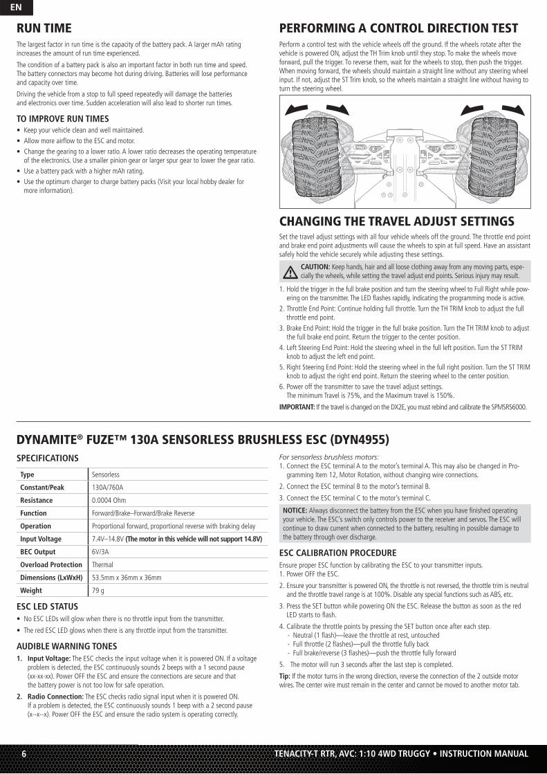
PERFORMING A CONTROL DIRECTION TESTPerform a control test with the vehicle wheels off the ground. If the wheels rotate after the vehicle is powered ON, adjust the TH Trim knob until they stop. To make the wheels move forward, pull the trigger. To reverse them, wait for the wheels to stop, then push the trigger. When moving forward, the wheels should maintain a straight line without any steering wheel input. If not, adjust the ST Trim knob, so the wheels maintain a straight line without having to turn the steering wheel.
CHANGING THE TRAVEL ADJUST SETTINGSSet the travel adjust settings with all four vehicle wheels off the ground. The throttle end point and brake end point adjustments will cause the wheels to spin at full speed. Have an assistant safely hold the vehicle securely while adjusting these settings.
CAUTION: Keep hands, hair and all loose clothing away from any moving parts, espe-cially the wheels, while setting the travel adjust end points. Serious injury may result.
1. Hold the trigger in the full brake position and turn the steering wheel to Full Right while pow-ering on the transmitter. The LED fl ashes rapidly, indicating the programming mode is active.
2. Throttle End Point: Continue holding full throttle. Turn the TH TRIM knob to adjust the full throttle end point.
3. Brake End Point: Hold the trigger in the full brake position. Turn the TH TRIM knob to adjust the full brake end point. Return the trigger to the center position.
4. Left Steering End Point: Hold the steering wheel in the full left position. Turn the ST TRIM knob to adjust the left end point.
5. Right Steering End Point: Hold the steering wheel in the full right position. Turn the ST TRIM knob to adjust the right end point. Return the steering wheel to the center position.
6. Power off the transmitter to save the travel adjust settings.The minimum Travel is 75%, and the Maximum travel is 150%.
IMPORTANT: If the travel is changed on the DX2E, you must rebind and calibrate the SPMSRS6000.
SPECIFICATIONS
Type Sensorless
Constant/Peak 130A/760A
Resistance 0.0004 Ohm
Function Forward/Brake–Forward/Brake Reverse
Operation Proportional forward, proportional reverse with braking delay
Input Voltage 7.4V–14.8V (The motor in this vehicle will not support 14.8V)
BEC Output 6V/3A
Overload Protection Thermal
Dimensions (LxWxH) 53.5mm x 36mm x 36mm
Weight 79 g
ESC LED STATUS• No ESC LEDs will glow when there is no throttle input from the transmitter.
• The red ESC LED glows when there is any throttle input from the transmitter.
AUDIBLE WARNING TONES1. Input Voltage: The ESC checks the in put voltage when it is powered ON. If a voltage
problem is detected, the ESC continuously sounds 2 beeps with a 1 second pause (xx-xx-xx). Power OFF the ESC and ensure the connections are secure and that the battery power is not too low for safe operation.
2. Radio Connection: The ESC checks radio signal input when it is powered ON. If a problem is detected, the ESC continuously sounds 1 beep with a 2 second pause (x--x--x). Power OFF the ESC and ensure the radio system is operating correctly.
For sensorless brushless motors:1. Connect the ESC terminal A to the motor’s terminal A. This may also be changed in Pro-
gramming Item 12, Motor Rotation, without changing wire connections.
2. Connect the ESC terminal B to the motor’s terminal B.
3. Connect the ESC terminal C to the motor’s terminal C.
NOTICE: Always disconnect the battery from the ESC when you have fi nished operating your vehicle. The ESC’s switch only controls power to the receiver and servos. The ESC will continue to draw current when connected to the battery, resulting in possible damage to the battery through over discharge.
ESC CALIBRATION PROCEDUREEnsure proper ESC function by calibrating the ESC to your transmitter inputs.1. Power OFF the ESC.
2. Ensure your transmitter is powered ON, the throttle is not reversed, the throttle trim is neutral and the throttle travel range is at 100%. Disable any special functions such as ABS, etc.
3. Press the SET button while powering ON the ESC. Release the button as soon as the red LED starts to fl ash.
4. Calibrate the throttle points by pressing the SET button once after each step. - Neutral (1 fl ash)—leave the throttle at rest, untouched - Full throttle (2 fl ashes)—pull the throttle fully back - Full brake/reverse (3 fl ashes)—push the throttle fully forward
5. The motor will run 3 seconds after the last step is completed.
Tip: If the motor turns in the wrong direction, reverse the connection of the 2 outside motor wires. The center wire must remain in the center and cannot be moved to another motor tab.
DYNAMITE® FUZE™ 130A SENSORLESS BRUSHLESS ESC (DYN4955)
7
EN
TENACITY-T RTR, AVC: 1:10 4WD TRUGGY • INSTRUCTION MANUAL
DESCRIPTIONS1. Running Mode
- Forward Only with BrakeIntended for competition use, this mode allows only forward and brake controls.
- Forward/Reverse with BrakeThis mode is the basic all-around mode, allowing forward, reverse and brake controls. To engage reverse while moving forward, apply the brake until the vehicle has come to a complete stop, release brake, then apply the brake again. While braking or in reverse, engaging the throttle will result in the vehicle immediately accelerating forward.
2. Drag Brake ForceAdjusts the amount of brake automatically applied when the throttle is returned to the neutral position. This simulates the engine braking effect of a full-scale vehicle, allowing improved turn-in and your vehicle’s general response to controls.
3. Low Voltage CutoffThis function helps to prevent battery over-discharge. The ESC continuously monitors the battery’s voltage. If the voltage falls below the voltage threshold for 2 seconds, the output power shuts off and the red LED fl ashes twice repeatedly.
The cutoff threshold calculation is based on individual Li-Po cell voltage. For Ni-MH batteries, if the voltage battery pack is higher than 9.0V, it will be treated as a 3-cell Li-Po battery pack; if it is lower than 9.0V, it will be treated as a 2-cell Li-Po battery pack. Example: for a 8.0V Ni-MH battery pack used with a 2.6V/cell threshold, it will be treated as a 2-cell Li-Po battery pack and the low-voltage cut-off threshold will be 5.2V (2.6x2=5.2).
4. Start Mode (Punch)Sets the initial throttle punch when the car accelerates. Level 1 gives a very soft initial acceleration and level 4 gives a stronger initial acceleration.
5. Max Brake ForceAdjusts the maximum braking force. A higher value provides stronger braking, but can also cause the wheels to lock, resulting in loss of control of the car.
6. Max Reverse ForceThis parameter adjusts the maximum power when travelling in reverse.
7. Initial Brake Force (minimum brake)Adjusts the minimum amount of braking power when the brakes engage. The default value is equal to the drag brake value. A high value can lock the wheels when the brake is used.
8. Neutral RangeAdjusts the throttle sensitivity around the neutral point. A higher value results in the throttle having to be moved more for the vehicle to move forward, backward or brake.
9. TimingAdjusts the motor drive current timing. More timing gives more performance, but can lower effi ciency and cause damage to the motor and/or ESC by overload or overheating.
NOTICE: Always ensure the motor timing is set correctly. Failure to set the motor timing correctly can result in damage to the motor and ESC. Refer to the manufacturer instructions for recommended timing settings.
The Following Programmable Items require the optional Digital ESC Program Box:
10. and 11. Available Items are subject to fi rmware updates to the ESC and the optional digital program box.
12. Motor RotationAllows you to make this change in the ESC so no wires need to be changed between the ESC and the motor.
13. Li-Po CellsAllows the ESC to automatically detect or manually set the number of cells in your Li-Po battery back.
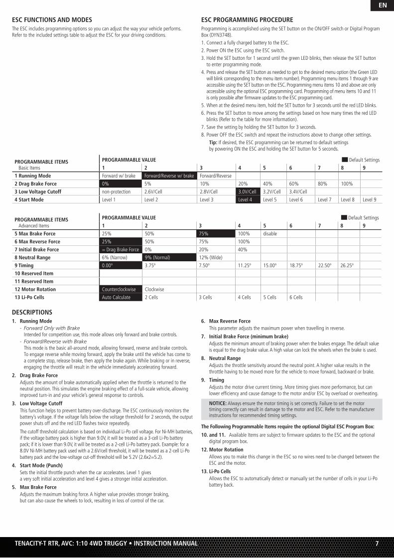
PROGRAMMABLE ITEMSBasic Items
PROGRAMMABLE VALUE Default Settings
1 2 3 4 5 6 7 8 9
1 Running Mode Forward w/ brake Forward/Reverse w/ brake Forward/Reverse
2 Drag Brake Force 0% 5% 10% 20% 40% 60% 80% 100%
3 Low Voltage Cutoff non-protection 2.6V/Cell 2.8V/Cell 3.0V/Cell 3.2V/Cell 3.4V/Cell
4 Start Mode Level 1 Level 2 Level 3 Level 4 Level 5 Level 6 Level 7 Level 8 Level 9
PROGRAMMABLE ITEMSAdvanced Items
PROGRAMMABLE VALUE Default Settings
1 2 3 4 5 6 7 8 9
5 Max Brake Force 25% 50% 75% 100% disable
6 Max Reverse Force 25% 50% 75% 100%
7 Initial Brake Force = Drag Brake Force 0% 20% 40%
8 Neutral Range 6% (Narrow) 9% (Normal) 12% (Wide)
9 Timing 0.00º 3.75º 7.50º 11.25º 15.00º 18.75º 22.50º 26.25º
10 Reserved Item
11 Reserved Item
12 Motor Rotation Counterclockwise Clockwise
13 Li-Po Cells Auto Calculate 2 Cells 3 Cells 4 Cells 5 Cells 6 Cells
ESC FUNCTIONS AND MODESThe ESC includes programming options so you can adjust the way your vehicle performs. Refer to the included settings table to adjust the ESC for your driving conditions.
ESC PROGRAMMING PROCEDUREProgramming is accomplished using the SET button on the ON/OFF switch or Digital Program Box (DYN3748).1. Connect a fully charged battery to the ESC.2. Power ON the ESC using the ESC switch.3. Hold the SET button for 1 second until the green LED blinks, then release the SET button
to enter programming mode.4. Press and release the SET button as needed to get to the desired menu option (the Green LED
will blink corresponding to the menu item number). Programming menu items 1 through 9 are accessible using the SET button on the ESC. Programming menu items 10 and above are only accessible using the optional ESC programming card. Programming of menu items 10 and 11is only possible after fi rmware updates to the ESC programming card.
5. When at the desired menu item, hold the SET button for 3 seconds until the red LED blinks. 6. Press the SET button to move among the settings based on how many times the red LED
blinks (Refer to the table for more information).7. Save the setting by holding the SET button for 3 seconds.8. Power OFF the ESC switch and repeat the instructions above to change other settings.
Tip: If desired, the ESC programming can be returned to default settings by powering ON the ESC and holding the SET button for 5 seconds.
EN
8 TENACITY-T RTR, AVC: 1:10 4WD TRUGGY • INSTRUCTION MANUAL
PRECAUTIONS• Never touch moving parts.
• Never disassemble while the batteries are installed.
• Always let parts cool before touching.
GEARING Your vehicle has been equipped with the optimal gearing for the use of a 2S battery. It offers an ideal balance between speed, power and effi ciency. Should you decide to customize your vehicle with a 3S battery it is necessary to change to a 12T pinion (included).
Installing a pinion gear with fewer teeth or a spur gear with more teeth will provide greater torque but will reduce top speed. Likewise, a pinion gear with more teeth or a spur gear with fewer teeth will reduce torque and increase top speed. Care should be taken when installing larger pinion gears as this can “overgear” the vehicle, resulting in overheating of the motor and ESC. When testing different gearing options, pay close attention to the temperature of the motor and speed control to ensure you are operating within the temperature range of the components. The motor or ESC should never be so hot that it cannot be touched. If tempera-tures are too hot, a different gearing combination with a lower pinion gear and/or higher spur gear is suggested.
CHANGING THE PINION GEAR/GEAR RATIO1. Remove screw holding the pinion gear cover in place.
2. Loosen the set screw and remove the installed pinion gear.
3. Loosen the motor screws and slide the motor back.
4. Place the new pinion on the end of the motor shaft so the set screw is located over the fl at on the shaft.
5. Position it so the teeth line up with the spur gear and secure the pinion by tightening the set screw.
6. Set the gear mesh.
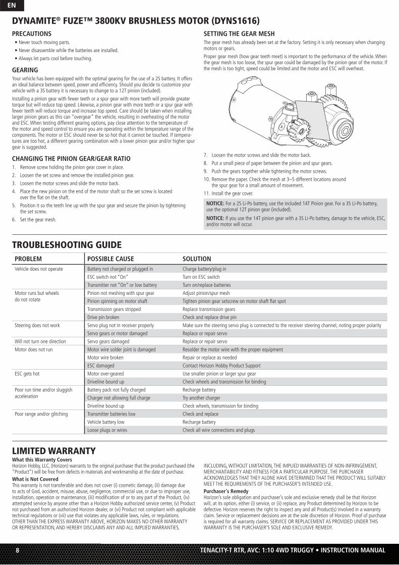
DYNAMITE® FUZE™ 3800KV BRUSHLESS MOTOR (DYNS1616)SETTING THE GEAR MESHThe gear mesh has already been set at the factory. Setting it is only necessary when changing motors or gears.
Proper gear mesh (how gear teeth meet) is important to the performance of the vehicle. When the gear mesh is too loose, the spur gear could be damaged by the pinion gear of the motor. If the mesh is too tight, speed could be limited and the motor and ESC will overheat.
7. Loosen the motor screws and slide the motor back.
8. Put a small piece of paper between the pinion and spur gears.
9. Push the gears together while tightening the motor screws.
10. Remove the paper. Check the mesh at 3–5 different locations around the spur gear for a small amount of movement.
11. Install the gear cover.
NOTICE: For a 2S Li-Po battery, use the included 14T Pinion gear. For a 3S Li-Po battery, use the optional 12T pinion gear (included).
NOTICE: If you use the 14T pinion gear with a 3S Li-Po battery, damage to the vehicle, ESC, and/or motor will occur.
TROUBLESHOOTING GUIDEPROBLEM POSSIBLE CAUSE SOLUTIONVehicle does not operate Battery not charged or plugged in Charge battery/plug in
ESC switch not “On” Turn on ESC switch
Transmitter not “On” or low battery Turn on/replace batteries
Motor runs but wheels do not rotate
Pinion not meshing with spur gear Adjust pinion/spur mesh
Pinion spinning on motor shaft Tighten pinion gear setscrew on motor shaft fl at spot
Transmission gears stripped Replace transmission gears
Drive pin broken Check and replace drive pin
Steering does not work Servo plug not in receiver properly Make sure the steering servo plug is connected to the receiver steering channel, noting proper polarity
Servo gears or motor damaged Replace or repair servo
Will not turn one direction Servo gears damaged Replace or repair servo
Motor does not run Motor wire solder joint is damaged Resolder the motor wire with the proper equipment
Motor wire broken Repair or replace as needed
ESC damaged Contact Horizon Hobby Product Support
ESC gets hot Motor over-geared Use smaller pinion or larger spur gear
Driveline bound up Check wheels and transmission for binding
Poor run time and/or sluggish acceleration
Battery pack not fully charged Recharge battery
Charger not allowing full charge Try another charger
Driveline bound up Check wheels, transmission for binding
Poor range and/or glitching Transmitter batteries low Check and replace
Vehicle battery low Recharge battery
Loose plugs or wires Check all wire connections and plugs
LIMITED WARRANTY What this Warranty CoversHorizon Hobby, LLC, (Horizon) warrants to the original purchaser that the product purchased (the “Product”) will be free from defects in materials and workmanship at the date of purchase. What is Not CoveredThis warranty is not transferable and does not cover (i) cosmetic damage, (ii) damage due to acts of God, accident, misuse, abuse, negligence, commercial use, or due to improper use, installation, operation or maintenance, (iii) modifi cation of or to any part of the Product, (iv) attempted service by anyone other than a Horizon Hobby authorized service center, (v) Product not purchased from an authorized Horizon dealer, or (vi) Product not compliant with applicable technical regulations or (vii) use that violates any applicable laws, rules, or regulations. OTHER THAN THE EXPRESS WARRANTY ABOVE, HORIZON MAKES NO OTHER WARRANTY OR REPRESENTATION, AND HEREBY DISCLAIMS ANY AND ALL IMPLIED WARRANTIES,
INCLUDING, WITHOUT LIMITATION, THE IMPLIED WARRANTIES OF NON-INFRINGEMENT, MERCHANTABILITY AND FITNESS FOR A PARTICULAR PURPOSE. THE PURCHASER ACKNOWLEDGES THAT THEY ALONE HAVE DETERMINED THAT THE PRODUCT WILL SUITABLY MEET THE REQUIREMENTS OF THE PURCHASER’S INTENDED USE. Purchaser’s RemedyHorizon’s sole obligation and purchaser’s sole and exclusive remedy shall be that Horizon will, at its option, either (i) service, or (ii) replace, any Product determined by Horizon to be defective. Horizon reserves the right to inspect any and all Product(s) involved in a warranty claim. Service or replacement decisions are at the sole discretion of Horizon. Proof of purchase is required for all warranty claims. SERVICE OR REPLACEMENT AS PROVIDED UNDER THIS WARRANTY IS THE PURCHASER’S SOLE AND EXCLUSIVE REMEDY.
9
EN
TENACITY-T RTR, AVC: 1:10 4WD TRUGGY • INSTRUCTION MANUAL
5 cm
Country of Purchase Horizon Hobby Contact Information Address
United States of America
Horizon Service Center(Repairs and Repair Requests)
servicecenter.horizonhobby.com/RequestForm/
4105 Filedstone Rd.Champaign, Illinois 61822 USA
Horizon Product Support(Product Technical Assistance)
European UnionHorizon Technischer Service [email protected]
+49 (0) 4121 2655 100Hanskampring 9D 22885 Barsbüttel, GermanySales: Horizon Hobby GmbH
WARRANTY AND SERVICE CONTACT INFORMATION
FCC STATEMENTFCC ID: BRWDX2EQ2UCFCC ID: BRWDASRX12This device complies with part 15 of the FCC rules. Operation is subject to the following two conditions: (1) This device may not cause harmful interference, and (2) this device must accept any interference received, including interference that may cause undesired operation.
CAUTION: Changes or modifi cations not expressly approved by the party responsible for compliance could void the user’s authority to operate the equipment.
This product contains a radio transmitter with wireless technology which has been tested and found to be compliant with the applicable regulations governing a radio transmitter in the 2.400GHz to 2.4835GHz frequency range.This equipment has been tested and found to comply with the limits for Part 15 of the FCC rules. These limits are designed to provide reasonable protection against harmful interference in a residential installation. This equipment generates, uses and can radiate radio frequency energy and, if not installed and used in accordance with the instructions, may cause harmful interference to radio communications.However, there is no guarantee that interference will not occur in a particular installation. If this equipment does cause harmful interference to radio or television reception, which can be determined by turning the equipment off and on, the user is encouraged to try to correct the interference by one or more of the following measures:
• Reorient or relocate the receiving antenna.• Increase the separation between the equipment and receiver.• Connect the equipment to an outlet on a circuit different from that
to which the receiver is connected.Antenna Separation DistanceWhen operating your Spektrum transmitter, please be sure to maintain a separation distance of at least 5 cm between your body (excluding fi ngers, hands, wrists, ankles and feet) and the antenna to meet RF exposure safety requirements as determined by FCC regulations.The illustration shows the approximate 5 cm RF exposure area and typical hand placement when operating your Spektrum transmitter.
IC INFORMATIONIC: 6157A-DX2EQ2UCIC: 6157A-AMRX12This device complies with Industry Canada licence-exempt RSS standard(s). Operation is subject to the following two conditions: (1) this device may not cause interference, and (2) this device must accept any interference, including interference that may cause undesired operation of the device.
EU Compliance Statement: Horizon Hobby, LLC hereby declares that this product is in compliance with the essential requirements and other relevant provisions of the RED and EMC Directive.
A copy of the EU Declaration of Conformity is available online at:http://www.horizonhobby.com/content/support-render-compliance.
Instructions for disposal of WEEE by users in the European UnionThis product must not be disposed of with other waste. Instead, it is the user’s responsibility to dispose of their waste equipment by handing it over to a designated collections point for the recycling of waste electrical and electronic equipment. The separate collection and recycling of your waste equipment at the
time of disposal will help to conserve natural resources and ensure that it is recycled in a manner that protects human health and the environment. For more information about where you can drop off your waste equipment for recycling, please contact your local city offi ce, your household waste disposal service or where you purchased the product.
Limitation of LiabilityHORIZON SHALL NOT BE LIABLE FOR SPECIAL, INDIRECT, INCIDENTAL OR CONSEQUENTIAL DAMAGES, LOSS OF PROFITS OR PRODUCTION OR COMMERCIAL LOSS IN ANY WAY, REGARDLESS OF WHETHER SUCH CLAIM IS BASED IN CONTRACT, WARRANTY, TORT, NEGLIGENCE, STRICT LIABILITY OR ANY OTHER THEORY OF LIABILITY, EVEN IF HORIZON HAS BEEN ADVISED OF THE POSSIBILITY OF SUCH DAMAGES. Further, in no event shall the liability of Horizon exceed the individual price of the Product on which liability is asserted. As Horizon has no control over use, setup, fi nal assembly, modifi cation or misuse, no liability shall be assumed nor accepted for any resulting damage or injury. By the act of use, setup or assembly, the user accepts all resulting liability. If you as the purchaser or user are not prepared to accept the liability associated with the use of the Product, purchaser is advised to return the Product immediately in new and unused condition to the place of purchase.LawThese terms are governed by Illinois law (without regard to confl ict of law principals). This warranty gives you specifi c legal rights, and you may also have other rights which vary from state to state. Horizon reserves the right to change or modify this warranty at any time without notice.WARRANTY SERVICESQuestions, Assistance, and ServicesYour local hobby store and/or place of purchase cannot provide warranty support or service. Once assembly, setup or use of the Product has been started, you must contact your local distributor or Horizon directly. This will enable Horizon to better answer your questions and service you in the event that you may need any assistance. For questions or assistance, please visit our website at www.horizonhobby.com, submit a Product Support Inquiry, or call the toll free telephone number referenced in the Warranty and Service Contact Information section to speak with a Product Support representative. Inspection or ServicesIf this Product needs to be inspected or serviced and is compliant in the country you live and use the Product in, please use the Horizon Online Service Request submission process found on our website or call Horizon to obtain a Return Merchandise Authorization (RMA) number. Pack the Product securely using a shipping carton. Please note that original boxes may be included, but are not designed to withstand the rigors of shipping without additional protection. Ship via a carrier that provides tracking and insurance for lost or damaged parcels, as Horizon is not responsible for merchandise until it arrives and is accepted at our facility. An Online Service Request is available at http://www.horizonhobby.com/content/service-
center_render-service-center. If you do not have internet access, please contact Horizon Product Support to obtain a RMA number along with instructions for submitting your product for service. When calling Horizon, you will be asked to provide your complete name, street address, email address and phone number where you can be reached during business hours. When sending product into Horizon, please include your RMA number, a list of the included items, and a brief summary of the problem. A copy of your original sales receipt must be included for warranty consideration. Be sure your name, address, and RMA number are clearly written on the outside of the shipping carton.
NOTICE: Do not ship Li-Po batteries to Horizon. If you have any issue with aLi-Po battery, please contact the appropriate Horizon Product Support offi ce.
Warranty Requirements For Warranty consideration, you must include your original sales receipt verifying the proof-of-purchase date. Provided warranty conditions have been met, your Product will be serviced or replaced free of charge. Service or replacement decisions are at the sole discretion of Horizon.Non-Warranty ServiceShould your service not be covered by warranty, service will be completed and payment will be required without notifi cation or estimate of the expense unless the expense exceeds 50% of the retail purchase cost. By submitting the item for service you are agreeing to payment of the service without notifi cation. Service estimates are available upon request. You must include this request with your item submitted for service. Non-warranty service estimates will be billed a minimum of ½ hour of labor. In addition you will be billed for return freight. Horizon accepts money orders and cashier’s checks, as well as Visa, MasterCard, American Express, and Discover cards. By submitting any item to Horizon for service, you are agreeing to Horizon’s Terms and Conditions found on our website http://www.horizonhobby.com/content/service-center_render-service-center.
ATTENTION: Horizon service is limited to Product compliant in the country of use and ownership. If received, a non-compliant Product will not be serviced. Further, the sender will be responsible for arranging return shipment of theun-serviced Product, through a carrier of the sender’s choice and at the sender’s expense. Horizon will hold non-compliant Product for a period of60 days from notifi cation, after which it will be discarded.
10/15
COMPLIANCE INFORMATION FOR THE EUROPEAN UNION

34 TENACITY T RTR, AVC: 1:10 4WD TRUGGY • MANUALE DI ISTRUZIONI
REPLACEMENT PARTS // TEILELISTE // LISTE DES PIÈCES DE RECHANGE // ELENCO DEI RICAMBIPart # English Deutsch Français Italiano
DYN4955 Fuze 130A BL ESC: 4WD SCT 1/8 WP Fuze 130 A Sensorloser Bl WP Geschwindig-keitsregler: 4WD SCT 1/8
Contrôleur Brushless étanche Fuze 130A Sensor-less pour SCT 4WD 1/8
ESC brushless waterproof Fuze 130 A senza sensori: SCT 4WD 1:8
DYNS1616 FUZE 550 BL Motor 3800kv FUZE 550 bürstenloser Motor 3800 kV Moteur Brushless Fuze 550, 3800Kv Motore brushless FUZE 550 3800 KvLOS230037 Body,Painted,White: TENACITY MT Karosserie, lackiert, Weiß: TENACITY MT Carrosserie, peinte, blanche: TENACITY MT Carrozzeria, verniciata, bianca: TENACITY MTLOS230038 Body,Painted,Blue:TENACITY MT Karosserie, lackiert, Blau: TENACITY MT Carrosserie, peinte, bleu: TENACITY MT Carrozzeria, verniciata, argento: TENACITY MTiLOS230043 Body Set,Ptd:TENACITYT BLK/BLU Karosseriesatz, lackiert, SCHWARZ/BLAU Carrosserie peinte noire/bleu Set carrozzeria, verniciata, NERO/BLULOS230044 Body Set,Ptd:TENACITYT WHT/GRN Karosseriesatz, lackiert, WEISS/GRÜN Carrosserie peinte blanche/Vert Set carrozzeria, verniciata, BIANCO/VERDELOS230045 Wing:TENACITY T Flügel:TENACITY T Aileron:TENACITY T Alettone:TENACITY TLOS230046 Body & Wing Mnt Set: TENACITY T Flügel-Karosseriehalterung Aileron, Set Montage Carrosserie Set supporto carrozzeria, alettoneLOS231023 Chassis: TENACITY SCT Fahrgestell Châssis TelaioLOS231024 Radio Box Set: TENACITY SCT Funkgerätkastensatz Boitier Radio Set Scocca RadiocomandoLOS231025 Shock Tower Set: TENACITY SCT STOSSDÄMPFERSATZ Support d'amortisseurs SET TORRE AMMORTIZZATORELOS231026 Steer BellcrankSet:TENACITY SCT STEUERHEBELSATZ Renvois de direction SET SQUADRETTE STERZOLOS231027 Steer Pst/Tubes&HDWE:TENACITYSCT Lenksäulen/Rohre und Hardware Pivots/commandes de direction & visserie Comandi/tubi sterzo e accessoriLOS231030 Chassis Support Set Fahrgestellstützsatz Support châssis Set supporto telaioLOS231031 Motor Mount: TENACITY SCT Motorhalterung Support moteur Supporto motoreLOS231032 Battery Box: TENACITY SCT Akkukasten Boitier batterie Scatola batteriaLOS231033 SteeringDragLink&Hdwe: TENACITY Spurstangenverbindung und Hardware Biellette de commande de direction & visserie Rinvio trascinamento sterzo e accessoriLOS232023 Diff Case Set: TENACITY SCT DIFFERENTIALSGEHÄUSESATZ Corps de différentiel SET SCATOLA DIFFERENZIALELOS232024 CenterDrive Coupler:TENACITY SC Zentralantriebskupplung Liaison cardan central Accoppiatore trasmissione centraleLOS232025 40T SpurGear,Mod 1:TENACITY SCT 40T Stirnradgetriebe, Mod 1 Couronne 40T, Mod 1 Ingranaggio cilindrico 40T, modalità 1LOS232026 Diff Housing: TENACITY SCT Differentialgehäuse, integrierter Einsatz Corps de différentiel, insert intégré Scatola differenziale, inserto integrato
LOS232027 FrRing&PinGearSet:TENACITY SCT Frontring und Zahnradgetriebesatz Couronne de différentiel avant et pignon d'attaque Set pignone e fascia anteriore
LOS232028 R Ring&PinGearSet:TENACITY SCT Heckring und Zahnradgetriebesatz Couronne de différentiel arrière et pignon d'attaque Set pignone e fascia posteriore
LOS232029 DiffGearSet w/Hardware:TENACITY Differentialgetriebesatz mit Hardware Différentiel avec visserie Set ingranaggio differenziale con accessoriLOS232030 Outdrive, Diff (2):TENACITY SCT Außenliegende Differentiale (2) Noix de cardan, différentiel (2) Trascinatore, differenziale (2)LOS232031 Wheel Hex Set (4):TENACITY SCT Radsechskantsatz (4) Hexagones de roues (4) Set esagoni ruote (4)LOS232032 Fr/R Driveshafts(2):TENACITY SCT Front-/Heckantriebswellen (2) Cardan avant/arrière (2) Alberi di trasmissione ant./post. (2)LOS232033 FRCenter Dogbone(2):TENACITY SCT Mittlerer Front-Dogbone (2) Cardan central avant (2) Cardano centrale ant. (2)LOS232034 R Center Dogbone(2):TENACITY SCT Mittlerer Heck-Dogbone (2) Cardan central arrière (2) Cardano centrale post. (2)
LOS233011 Shock Plastics Set:TENACITY SCT KUNSTSTOFF-STOSSDÄMPFERSATZ Plastique amortisseurs SET COMPONENTI AMMORTIZZATORI IN PLASTICA
LOS233012 FR & R Shock Body: TENACITY SCT Front- und Heckstoßdämpfergehäuse Corps d'amortisseurs avant & arrière Corpo ammortizzatore ant. e post.LOS233013 Spring Set: TENACITY SCT Federsatz Ressort Set molleLOS233014 RearShockShaft(2):TENACITY SCT Hintere Stoßdämpferwelle (2) Tige d'amortisseur arrière (2) Albero ammortizzatore posteriore (2)LOS233015 FrontShockShaft(2):TENACITY SCT Vordere Stoßdämpferwelle (2) Tige d'amortisseur avant (2) Albero ammortizzatore anteriore (2)LOS234016 Front Arm Set: TENACITY SCT FRONTARMSATZ Bras avant SET BRACCIO ANTERIORELOS234017 Rear Arm Set: TENACITY SCT HECKARMSATZ Bras arrière SET BRACCIO POSTERIORELOS234018 FR Spndl&Carrier St:TENACITY VORDERER SPINDEL- UND SCHLITTENSATZ Fusée avant & étrier SET FUSELLO E PORTAFUSELLO ANTERIORE
LOS234019 FR/R PinMntCover St:TENACITYSCT VORDERER/HINTERERStift-Halterungsabdeckungssatz
Protections de renforts de cellules avant et arrière Set copertura supporto ant./post. con perni
LOS234020 Rear Hubs Set: TENACITY SCT Hinterer Nabensatz Fusée arrière Set mozzi posterioriLOS234021 Hingepin&KingpinSet:TENACITY SC Scharnierbolzen- und Achsschenkelbolzen-Satz Axe de suspension & axes Set perni cerniere e perni fuso a snodoLOS234022 Camber Link Set:TENACITY SCT Sturzstangensatz Biellette de carrossage Set collegamenti campanaturaLOS234023 PivotPinMntSt,Steel(4):TENACITY Kippzapfen-Halterungssatz, Stahl (4) Goupilles de pivots, acier (4) Set supporto a perno girevole, acciaio (4)LOS235011 Set Screws M3x3mm Cup Point(10) Stellschrauben, M3 x 3 mm Ringschneide (10) Vis STHC M3 x 3mm CUV (10) Grani, M3 x 3 mm con punta a coppa (10)LOS235012 Set Screws M4x4mm Cup Point(10) Stellschrauben, M4 x 4 mm Ringschneide (10) Vis STHC M4 x 4mm CUV (10) Grano, M4 x 4 mm con punta a coppa (10)LOS235024 Button Head Screws M3x25mm (10) Halbrundschrauben M3x25mm (10) Vis à tête bombée M3x25mm (10) Viti a testa tonda M3x25mm (10)LOS235025 Button Head Screws M3x30mm (10) Halbrundschrauben M3x30mm (10) Vis à tête bombée M3x30mm (10) Viti a testa tonda M3x30mm (10)LOS235026 Set Screws,M3 x 4mm CupPoint(10) Stellschrauben, M3 x 4mm Ringschneide (10) Vis sans tête M3 x 4mm (10) Grani, M3 x 4 mm con punta a coppa (10)LOS235027 Set Screws,M3x10mm CupPoint(10) Stellschrauben, M3 x 10mm Ringschneide (10) Vis sans tête M3 x 10mm (10) Grani, M3 x 10 mm con punta a coppa (10)LOS236000 E-Clips 2.5mm (12) E-Clips 2,5 mm (12) E-Clips 2,5mm (12) E-clip 2,5 mm (12)LOS236001 3.2mm x 7mmx .5mm Washer(10) 3,2 mm x 7 mm x 0,5 mm Unterlegscheibe (10) Rondelle 3,2mm x 7mm x 0,5mm (10) Rondella 3,2 mm x 7 mm x .5 mm (10)LOS237000 12x18x4mm Ball Bearing (4) 12 x 18 x 4 mm Kugellager (4) Roulements 12 x 18 x 4mm (4) Cuscinetto a sfera 12 x 18 x 4 mm (4)LOS237001 10x15x4mm Ball Bearing (4) 10 x 15 x 4 mm Kugellager (4) Roulements 10 x 15 x 4mm (4) Cuscinetto a sfera 10 x 15 x 4 mm (4)LOS237002 5x11x4mm Ball Bearing (4) 5 x 11 x 4 mm Kugellager (4) Roulements 5 x 11 x 4mm (4) Cuscinetto a sfera 5 x 11 x 4 mm (4)LOS43018 Wheel and Tire Mounted, Blk Chr (2) Rad und Reifen befestigt, Schwarz (2) Pneu et jante monté, Noir (2) Ruota e pneumatico montati, Nero (2)LOS43019 Wheel and Tire Mounted, Blu Chr (2) Rad und Reifen befestigt, Blau (2) Pneu et jante monté, Bleu (2) Ruota e pneumatico montati, Blu (2)LOSA6940 6x12mm Sealed Ball Bearing (4) 6 x 12 mm geschlossenes Kugellager (4) Roulements étanches 6x12mm (4) Cuscinetto a sfera sigillato 6 x 12 mm (4)SPMS605 9KG Servo, WP, Metal, 23T 9KG Servo, WP, Metall, 23T Servo 9Kg à pignons métal, étanche, tête 23T Servo 9 kg, waterproof, metallo, 23TSPMSRS6000 SRS6000 DSMR AVC Surface Rx SRS6000 DSMR AVC Oberfl ächenempfänger Récepteur Surface SRS6000 DSMR AVC Ricevente di superfi cie SRS6000 DSMR con AVCTLR235007 Flat Head Screw M2.5 x 10mm (10 Flachkopfschraube M2,5 x 10 mm (10) Vis FHC M2,5 x 10mm (10) Viti a testa piatta M2,5 x 10 mm (10)TLR255008 Button Head Screws, M4x16mm (10) Halbrundschrauben, M4 x 16 mm (10) Vis à tête bombée, M4x16mm (10) Viti a testa tonda, M4 x 16 mm (10)TLR255013 Flat Head Screws, M4x12mm (10) Flachkopfschrauben, M4 x 12 mm (10) Vis à tête fraisée, M4x12mm (10) Viti a testa piatta, M4 x 12 mm (10)TLR256005 Nylock Nut, M4 (10) Einstellmutter, M4 (10) Écrou auto-freiné, M4 (10) Dado Nylock, M4 (10)

35TENACITY T RTR, AVC: 1:10 4WD TRUGGY • MANUALE DI ISTRUZIONI
REPLACEMENT PARTS // TEILELISTE // LISTE DES PIÈCES DE RECHANGE // ELENCO DEI RICAMBIPart # English Deutsch Français Italiano
TLR336005 M3 Flanged Alum Locknuts Blk(10 M3 gefl anschte Aluminium-Kontermuttern, Schwarz (10)
Écrou auto-freiné épaulé M3 en aluminium, noir (10)
Dadi autobloccanti a colletto M3 in alluminio, nero (10)
TLR5901 Button Hd Screws, M3 x 6mm (10) Halbrundschrauben, M3 x 6mm (10) Vis à tête bombée M3 x 6mm (10) Viti a testa tonda, M3 x 6mm (10)TLR5902 Button Hd Screws, M3 x 8mm (10) Halbrundschrauben, M3 x 8mm (10) Vis à tête bombée M3 x 8mm (10) Viti a testa tonda, M3 x 8mm (10)TLR5903 Button Hd Screws, M3 x 10mm (10) Halbrundschrauben, M3 x 10mm (10) Vis à tête bombée M3 x 10mm (10) Viti a testa tonda, M3 x 10mm (10)TLR5904 Button Hd Screws, M3 x 12mm (10) Halbrundschrauben, M3 x 12mm (10) Vis à tête bombée M3 x 12mm (10) Viti a testa tonda, M3 x 12mm (10)TLR5905 Button Hd Screws, M3 x 18mm (10) Halbrundschrauben, M3 x 18mm (10) Vis à tête bombée M3 x 18mm (10) Viti a testa tonda, M3 x 18mm (10)TLR5908 Button Hd Screws, M3 x 44mm (4) Halbrundschrauben, M3 x 44mm (4) Vis à tête bombée M3 x 44mm (4) Viti a testa tonda, M3 x 44mm (4)TLR5909 Button Head Screws, M3x16mm(10) Halbrundschrauben, M3x16mm(10) Vis à tête bombée M3x16mm(10) Viti a testa tonda, M3x16mm(10)TLR5910 Button Head Screws M3 x 14mm(10) Halbrundschrauben, M3 x 14mm(10 Vis à tête bombée M3 x 14mm(10 Viti a testa tonda, M3 x 14mm(10TLR5911 Button Head Screws,M3 x 20mm(10) Halbrundschrauben,M3 x 20mm(10) Vis à tête bombée M3 x 20mm(10) Viti a testa tonda, M3 x 20mm(10)TLR5914 Button Head Screws,M2 x 12mm(10 Halbrundschrauben,M2 x 12mm(10) Vis à tête bombée M2 x 12mm(10) Viti a testa tonda, M2 x 12mm(10)TLR5932 Cap Head Screws, M3 x 10mm (10) Kopfschrauben, M3 x 10mm (10) Vis BTR, M3 x 10mm (10) Viti a grano, M3 x 10mm (10)TLR5933 Cap Head Screws, M3 x 12mm (10) Kopfschrauben, M3 x 12mm (10) Vis BTR, M3 x 12mm (10) Viti a grano, M3 x 12mm (10)TLR5963 Flathead Screw, M3 x 12mm (10) Flachkopfschraube, M3 x 12 mm (10) Vis à tête plate M3 x 12mm (10) Viti a testa piatta M3 x 12 mm (10)TLR5964 Flathead Screw, M3 x 16mm (10) Flachkopfschraube, M3 x 16 mm (10) Vis à tête plate M3 x 16mm (10) Viti a testa piatta, M3 x 16 mm (10)TLR5965 Flathead Screw, M3 x 20mm (10) Flachkopfschraube, M3 x 20 mm (10) Vis à tête plate M3 x 20mm (10) Viti a testa piatta, M3 x 20 mm (10)TLR6313 Locknut, M3 x .5 x 5.5mm (10) Kontermutter, M3 x 0,5 x 5,5 mm (10) Ecrou M3 x 0,5 x 5,5mm (10) Dado autobloccante, M3 x .5 x 5,5 mm (10)TLR6352 Washers, M3 (10) Unterlegscheiben, M3 (10) Rondelles M3 (10) Rondelle, M3 (10)TLR74008 Silicone Shock Oil, 35 Wt, 2 Oz Silikonstoßdämpferöl, 35wt, 2 oz Huile silicone d’amortisseur, 35wt, 2oz Olio silicone ammortizzatori, 35wt, 2ozTLR8202 Body Clips, Black (12): 22 Karosserieklammern, Schwarz (12): 22 22 - Clips de carrosserie noirs (12) Clip carrozzeria, nero (12): 22
OPTIONAL PARTS // OPTIONALE TEILE // PIÈCES OPTIONNELLES // PARTI OPZIONALIPart # English Deutsch Français Italiano
DYNB3802EC 7.4V 5000mAh 2S50CLiPo,Hrdcs:EC3 7.4V 5000 mA 50C 2S LiPo, Hartschale:EC3 7.4V5000mA 50C, boitier rigide avec prise EC3 Batteria LiPo hardcase 7.4V 5000mAh 2S 50C: EC3
DYNB3803EC 11.1V5000mAh3S50CLiPo,Hrdcs:EC3 11.1V 5000 mA 50C 3S LiPo, Hartschale:EC3 11.1V 5000mA 50C, boitier rigide avec prise EC3 Batteria LiPo hardcase 11.1V 5000mAh 3S 50C: EC3
DYNC2005CA ProphetSport LiPo 35W AC Charge Prophet Sport Li-Po 35 W Wechselstrom-Akku-Ladegerät Chargeur Li-Po Prophet Sport 35W AC Caricabatteria AC Prophet Sport 35 W per
batterie LiPoDYN2834 Startup Tool Set: Metric Start-Tool-Set: Metrisch Set d'outils de démarrage: métrique Set di strumenti di avvio: metricoDYN5500 Magnum Force 2 Motor Spray, 13 oz Magnum Force 2 Motorspray, 13oz Nettoyant moteur Magnum Force 2, 13oz Spray per motori Magnum Force 2, 13ozDYNT2010 Machined Nut Driver St(4)MET Steckschlüsselset gefräst 4Stk. metrisch Clés à écrous usinées 4 pièces, métrique Set cacciaviti dadi lavorati, metrico (4)DYNT2030 Machined Hex Driver Set (4) Met Inbusschlüsselset (4) Metrisch Clés BTR usinées 4 pièces, métrique Set cacciaviti a brugola lavorati, metrico (4)LOS230042 Body Set, Clear Karosseriesatz, farblos Carrosserie transparente Set carrozzeria, trasparenteLOSA3571 1.0 Module Pitch Pinion,11T:8E,SCTE 1.0 Modul Getrieberad11T:8E,SCTE Pignon module 1.0,11T:8E,SCTE Pignone a passo modulare 1.0,11T:8E,SCTELOSA3572 1.0 Module Pitch Pinion,12T:8E,SCTE 1.0 Modul Getrieberad12T:8E,SCTE Pignon module 1.0,12T:8E,SCTE Pignone a passo modulare 1.0,12T:8E,SCTELOSA3573 1.0 Module Pitch Pinion,13T:8E,SCTE 1.0 Modul Getrieberad13T:8E,SCTE Pignon module 1.0,13T:8E,SCTE Pignone a passo modulare 1.0,13T:8E,SCTELOSA3575 1.0 Module Pitch Pinion,15T:8E,SCTE 1.0 Modul Getrieberad15T:8E,SCTE Pignon module 1.0,15T:8E,SCTE Pignone a passo modulare 1.0,15T:8E,SCTELOSA3576 1.0 Module Pitch Pinion,16T:8E, E 1.0 Modul Getrieberad16T:8E, E Pignon module 1.0,16T:8E, E Pignone a passo modulare 1.0,16T:8E, ELOSA99173 Ride Height Gauge Reiten Höhenmessgerät Jauge de hauteur Misuratore di altezza di corsaSPM6730 Spektrum Tx Storage Bag Aufbewahrungsbeutel Spektrum Tx Sac de rangement Spektrum Tx Sacchetto custodia Spektrum TxSPM6740 Optional Speedometer DX2E Optional Tachometer DX2E Compteur vitesse optionnel DX2E Tachimetro opzionale DX2ESPM6741 Optional Bluetooth Module DX2E Optional Bluetooth-Modul DX2E Module Bluetooth Optionnel DX2E Modulo Bluetooth opzionale DX2ESPM6742 TM1500 Telemetry Module TM1500 Telemetrie-Modul Module de télémesure TM1500 Modulo per telemetria TM1500SPM6743 DX2E ACTIVE Speedometer Bundle DX2E ACTIVE Tachometer bündeln Packet compteur vitesse DX2E ACTIVE Tachimetro DX2E ACTIVE BundleSPM6744 DX2E ACTIVE Dashboard Bundle DX2E ACTIVE Armaturenbrett bündeln Packet tableau de bord DX2E ACTIVE Cruscotto DX2E ACTIVE BundleSPM6745 DX2E ACTIVE Phone Mount Telefonhalterung DX2E ACTIVE Support pour téléphone DX2E ACTIVE Supporto del telefono DX2E ACTIVESPMSS6230 S6230 High Torque, Dig Servo S6230 Hochdrehmoment-Digital-Servo S6230 Servo numérique à couple élevé S6230 Servo digitale ad alta coppiaTLR336000 4mmAlumSerratedLockNuts,Black(6) 4mm Aluminium Stopmutter mit Flansch schwarz (6) Ecrou auto-freiné épaulé M4, aluminium, noire (6) Dado autobloccante 4mm dentellato, nero (6)TLR336001 4mmAlumSerratedLockNuts,Blue(6) 4mm Aluminium Stopmutter mit Flansch Blau (6) Ecrou auto-freiné épaulé M4, aluminium, bleu (6) Dado autobloccante 4mm dentellato, blu (6)TLR74006 Silicone Shock Oil, 30wt, 2oz Silikonstoßdämpferöl, 30wt, 2 oz Huile silicone d’amortisseur, 30wt, 2oz Olio silicone ammortizzatori, 30wt, 2ozTLR74010 Silicone Shock Oil, 40 Wt, 2 Oz Silikonstoßdämpferöl, 40wt, 2 oz Huile silicone d’amortisseur, 40wt, 2oz Olio silicone ammortizzatori, 40wt, 2ozTLR76004 TLR Lok, Threadlock, Blue TLR-Lok, Schraubensicherung, blau Frein fi let, TLR-Lok, bleu Frenafi letti, TLR Lok, blu
36 TENACITY T RTR, AVC: 1:10 4WD TRUGGY • MANUALE DI ISTRUZIONI
LOS231025
LOS234021
LOS234023
LOS234019
LOS230046
TLR5909
TLR5911
TLR5964
LOS234016
LOS234018LOS237001
LOS234021LOS234018
LOS232032
TLR5911
LOS234022
TLR6313
TLR5964
LOS234022
TLR6313
TLR5905
LOS235026
LOSA6940
LOS232031
LOS234016
TLR255008
LOS232026
LOS237000
LOS232030
LOS237000
LOS232027
LOS232023
TLR5933
LOS232030
LOS231027
LOS231027
LOS231026
TLR5904
TLR6313
TLR5904
TLR5910LOS234022
LOS231024
LOS234022
LOS231026
LOS231033
LOS232026TLR5963
TLR5964 LOS232029
LOS232023
TLR5904 TLR5964
LOS232027LOS237002
LOS237002
LOS232024
TLR235007
TLR255013
LOS230046
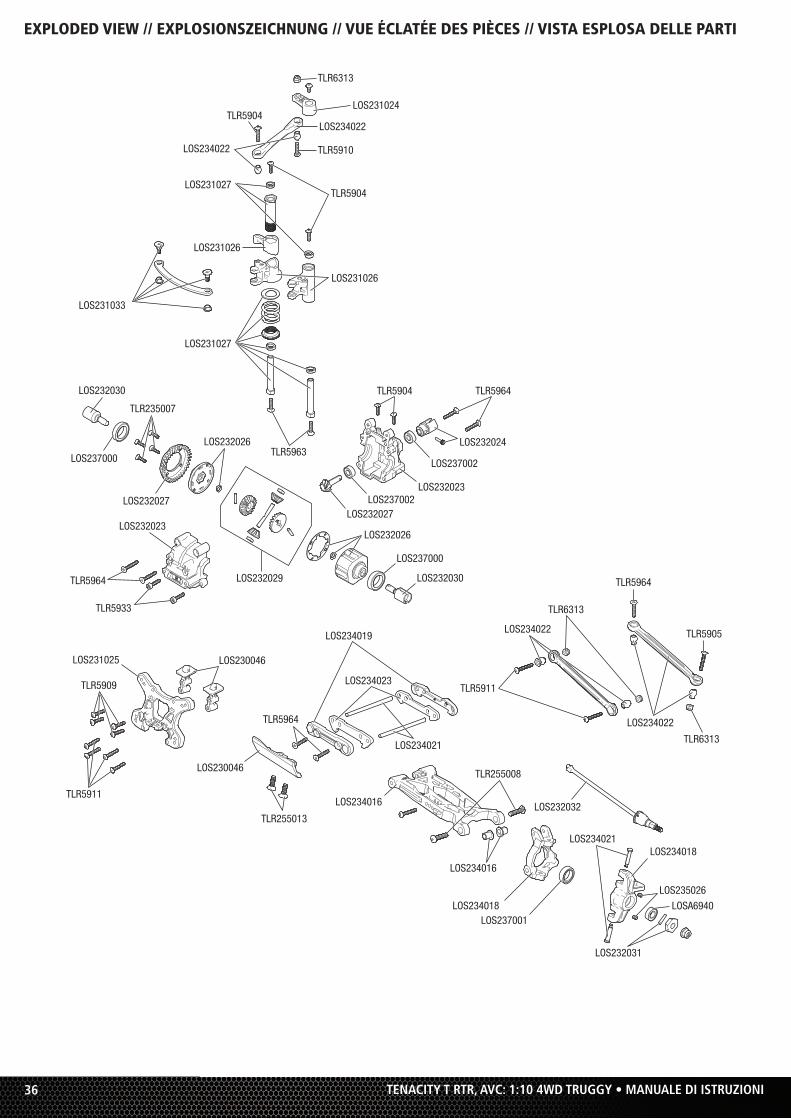
EXPLODED VIEW // EXPLOSIONSZEICHNUNG // VUE ÉCLATÉE DES PIÈCES // VISTA ESPLOSA DELLE PARTI

37TENACITY T RTR, AVC: 1:10 4WD TRUGGY • MANUALE DI ISTRUZIONI
TLR235007
LOS234022
LOS230046
LOS230046
LOS232032
LOS232030
LOS232030
LOS237000
LOS237000LOS232023
LOS232028
LOS237002
LOS237002
LOS232024
LOS232023
LOS232026
LOS232029
LOS232026
LOS232023
TLR5965
LOS232023
TLR5911
TLR5911TLR5909
TLR5909
TLR5905
LOS232031LOS237001
LOSA6940
LOS234021
LOS234023
TLR255013
TLR5963
LOS234020
LOS234021
TLR6313
TLR6313
TLR6313
TLR6313
LOS234017
LOS234019
LOS231025
TLR5911
TLR5908
EXPLODED VIEW // EXPLOSIONSZEICHNUNG // VUE ÉCLATÉE DES PIÈCES // VISTA ESPLOSA DELLE PARTI
38 TENACITY T RTR, AVC: 1:10 4WD TRUGGY • MANUALE DI ISTRUZIONI
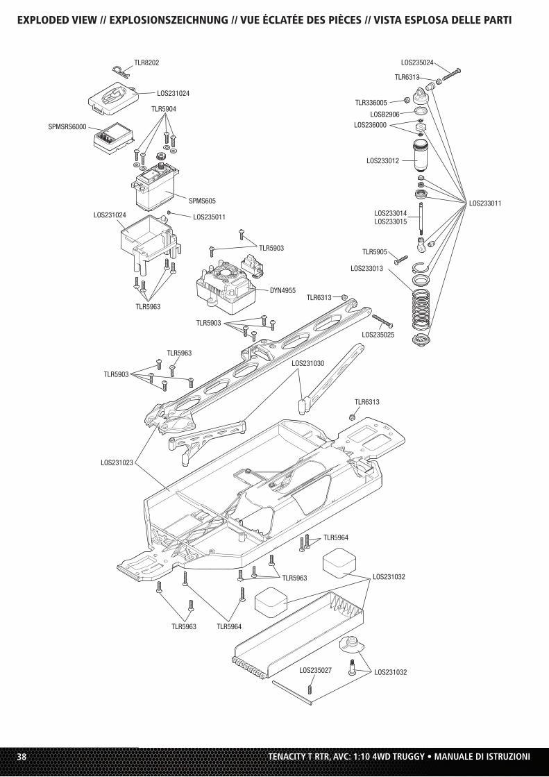
EXPLODED VIEW // EXPLOSIONSZEICHNUNG // VUE ÉCLATÉE DES PIÈCES // VISTA ESPLOSA DELLE PARTI
LOS231032
LOS235027 LOS231032
TLR5963 TLR5964
TLR5964
TLR5963
TLR6313
LOS231023
LOS235024
TLR5905
LOS233014LOS233015
TLR6313
LOS233011
LOS233013
LOS231030
TLR336005
LOSB2906
LOS233012
LOS236000
TLR8202
SPMS605
SPMSRS6000
DYN4955
TLR5903
TLR5904
TLR5903
TLR5903
TLR5963
TLR5963
LOS235011
LOS231024
LOS231024
LOS235025
TLR6313
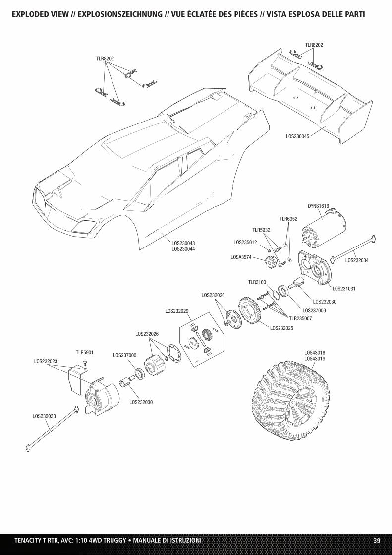
39TENACITY T RTR, AVC: 1:10 4WD TRUGGY • MANUALE DI ISTRUZIONI
EXPLODED VIEW // EXPLOSIONSZEICHNUNG // VUE ÉCLATÉE DES PIÈCES // VISTA ESPLOSA DELLE PARTI
DYNS1616
LOS230043LOS230044
LOS232029
LOS232025
TLR235007
LOS237000
TLR3100
LOS232030
LOS232033
LOS232023
LOS232030
LOS237000TLR5901
LOS232026
LOS232026
LOSA3574
LOS235012
TLR6352
TLR8202
TLR8202
TLR5932
LOS230045
LOS232034
LOS231031
LOS43018LOS43019

©2017 Horizon Hobby, LLC.
Losi, Tenacity, DSM, DSM2, DSMR, AVC, Active Vehicle Control, EC3, Dynamite, Fuze, Prophet and the Horizon Hobby logo are trademarks or
registered trademarks of Horizon Hobby, LLC. The Spektrum trademark is used with permission of Bachmann Industries, Inc.
US 9,320,977. Other patents pending.
Created 11/17 54571.1 LOS03011T1/T2
WWW.LOSI.COM