instruction manual e-8000 power supply/readout and … · 4.5.3 instrument i/o connection for pid...
TRANSCRIPT

Doc. no.: 9.17.076J Date: 26-06-2018
ATTENTIONPlease read this Instruction Manual carefully before installing and operating the instrument.
Not following the guidelines could result in personal injury and/or damage to the equipment.
E-8000Power Supply /
Readout and Control System
Instruction Manual

Bronkhorst®
Instruction Manual E-8000 Power Supply/Readout and Control System 9.17.076J2
Disclaimer
The information in this manual has been reviewed and is believed to be wholly reliable. No responsibility, however, is assumedfor inaccuracies. The material in this manual is for information purposes only.
Copyright
© 2018 Bronkhorst High-Tech B.V.All rights reserved. This documentation is protected by copyright.
Subject to technical and optical changes as well as printing errors. The information contained in this document is subject tochange at any time without prior notification. Bronkhorst High-Tech B.V. reserves the right to modify or improve its products andmodify the contents without being obliged to inform any particular persons or organizations. The device specifications and thecontents of the package may deviate from what is stated in this document.
Symbols
Important information. Disregarding this information could cause injuries to people or damage to the instrument orinstallation.
Helpful information. This information will facilitate the use of the instrument and/or contribute to its optimalperformance.
Additional info available on the internet or from your local sales representative.
Receipt of equipment
Check the outside package box for damage incurred during shipment. If the box is damaged, then the local carrier must benotified at once regarding his liability, if so required. At the same time a report should be submitted to your local salesrepresentative.
Carefully remove the equipment from the box. Verify that the equipment was not damaged during shipment. Should theequipment be damaged, then the local carrier must be notified at once regarding his liability, if so required. At the same time areport should be submitted to your local sales representative.
Check the packing list to ensure that you received all of the items within the scope of delivery.Do not discard spare or replacement parts with the packaging material and inspect the contents for damage.
Refer to Removal and return instructions about return shipment procedures.
Equipment storage
The equipment should be stored in its original package in a cupboard warehouse or similar. Care should be taken not to subjectthe equipment to excessive temperatures or humidity.

Bronkhorst®
Instruction Manual E-8000 Power Supply/Readout and Control System9.17.076J 3
Warranty
Bronkhorst® products are warranted against defects in material and workmanship for a period of three years from the date ofshipment, provided they are used in accordance with the ordering specifications and not subject to abuse or physical damage.Products that do not operate properly during this period may be repaired or replaced at no charge. Repairs are normallywarranted for one year or the balance of the original warranty, whichever is the longer.
See also section 9 (Guarantee) of the Conditions of sales:www.bronkhorst.com/about/conditions-of-sales/
The warranty includes all initial and latent defects, random failures, and indeterminable internal causes.
It excludes failures and damage caused by the customer, such as contamination, improper electrical hook-up, physical shock etc.
Re-conditioning of products primarily returned for warranty service that is partly or wholly judged non-warranty may be chargedfor.
Bronkhorst High-Tech B.V. or affiliated company prepays outgoing freight charges when any part of the service is performedunder warranty, unless otherwise agreed upon beforehand, however, if the product has been returned collect to our factory orservice center, these costs are added to the repair invoice. Import and/or export charges, foreign shipping methods/carriers arepaid by the customer.
General safety precautions
This product is intended for use by qualified personnel who recognize shock hazards and are familiar with the safety precautionsrequired to avoid possible injury. Read the operating information carefully before using the product.
Before operating, make sure the line cord is connected to a properly grounded power receptacle. Inspect the connecting cablesfor cracks or breaks before each use.
The equipment and accessories must be used in accordance with their specifications and operating instructions, otherwise thesafety of the equipment may be impaired.
If required, replace fuses with the same type and rating for continued protection against fire hazard.
Opening the equipment is not allowed. There are no repairable parts inside. In case of a defect please return the equipment toBronkhorst High-Tech B.V.
One or more warning signs may be present on different parts of the product. These signs have the following meaning:
Consult the instruction manual for handling instructions
Surface may get hot during operation
Shock hazard; electrical parts inside
To maintain protection from electric shock and fire, replacement components must be obtained from Bronkhorst. Standardfuses, with applicable national safety approvals, may be used if the rating and type are the same. Other components that are notsafety related may be obtained from other suppliers, as long as they are equivalent to the original component. Selected partsshould be obtained only through Bronkhorst, to maintain accuracy and functionality of the product. If you are unsure about therelevance of a replacement component, contact Bronkhorst for information.

Bronkhorst®
Instruction Manual E-8000 Power Supply/Readout and Control System 9.17.076J4

Bronkhorst®
Instruction Manual E-8000 Power Supply/Readout and Control System9.17.076J 5
Table of contents
. . . . . . . . . . . . . . . . . . . . . . . . . . . . . . . . . . . . . . . . . . . . . . . . . . . . . . . . . . . . . . . . . . . . . . . . . . . . . . . . . . . . . . . . . . . . . . . . . . . . . . . . . . . . 8Introduction 1. . . . . . . . . . . . . . . . . . . . . . . . . . . . . . . . . . . . . . . . . . . . . . . . . . . . . . . . . . . . . . . . . . . . . . . . . . . . . . . . . . . . . . . . . . . . . . . . . . . . . . . . . . . . 81.1 Scope of this manual . . . . . . . . . . . . . . . . . . . . . . . . . . . . . . . . . . . . . . . . . . . . . . . . . . . . . . . . . . . . . . . . . . . . . . . . . . . . . . . . . . . . . . . . . . . . . . . . . . . . . . . . . . . . 81.2 Other documents
. . . . . . . . . . . . . . . . . . . . . . . . . . . . . . . . . . . . . . . . . . . . . . . . . . . . . . . . . . . . . . . . . . . . . . . . . . . . . . . . . . . . . . . . . . . . . . . . . . . . . . . . . . . . 9Starting up 2. . . . . . . . . . . . . . . . . . . . . . . . . . . . . . . . . . . . . . . . . . . . . . . . . . . . . . . . . . . . . . . . . . . . . . . . . . . . . . . . . . . . . . . . . . . . . . . . . . . . . . . . . . . . 92.1 Functional properties . . . . . . . . . . . . . . . . . . . . . . . . . . . . . . . . . . . . . . . . . . . . . . . . . . . . . . . . . . . . . . . . . . . . . . . . . . . . . . . . . . . . . . . . . . . . . . . . . . . . . . . . . . . . 92.2 Install system
. . . . . . . . . . . . . . . . . . . . . . . . . . . . . . . . . . . . . . . . . . . . . . . . . . . . . . . . . . . . . . . . . . . . . . . . . . . . . . . . . . . . . . . . . . . . . . . . . . . . . . . . . . . . 102.3 Model key
. . . . . . . . . . . . . . . . . . . . . . . . . . . . . . . . . . . . . . . . . . . . . . . . . . . . . . . . . . . . . . . . . . . . . . . . . . . . . . . . . . . . . . . . . . . . . . . . . . . . . . . . . . . . 102.4 Housing
. . . . . . . . . . . . . . . . . . . . . . . . . . . . . . . . . . . . . . . . . . . . . . . . . . . . . . . . . . . . . . . . . . . . . . . . . . . . . . . . . . . . . . . . . . . . . . . . . . . . . . . . . . . . 10Housing table top 2.4.1
. . . . . . . . . . . . . . . . . . . . . . . . . . . . . . . . . . . . . . . . . . . . . . . . . . . . . . . . . . . . . . . . . . . . . . . . . . . . . . . . . . . . . . . . . . . . . . . . . . . . . . . . . . . . 11Housing panel/rack mount 2.4.2
. . . . . . . . . . . . . . . . . . . . . . . . . . . . . . . . . . . . . . . . . . . . . . . . . . . . . . . . . . . . . . . . . . . . . . . . . . . . . . . . . . . . . . . . . . . . . . . . . . . . . . . . . . . . 11Housing table top with handle 2.4.3
. . . . . . . . . . . . . . . . . . . . . . . . . . . . . . . . . . . . . . . . . . . . . . . . . . . . . . . . . . . . . . . . . . . . . . . . . . . . . . . . . . . . . . . . . . . . . . . . . . . . . . . . . . . . 12Housing dimensions 2.4.4
. . . . . . . . . . . . . . . . . . . . . . . . . . . . . . . . . . . . . . . . . . . . . . . . . . . . . . . . . . . . . . . . . . . . . . . . . . . . . . . . . . . . . . . . . . . . . . . . . . . . . . . . . . . . 122.5 Power supply
. . . . . . . . . . . . . . . . . . . . . . . . . . . . . . . . . . . . . . . . . . . . . . . . . . . . . . . . . . . . . . . . . . . . . . . . . . . . . . . . . . . . . . . . . . . . . . . . . . . . . . . . . . . . 132.6 Power consumption
. . . . . . . . . . . . . . . . . . . . . . . . . . . . . . . . . . . . . . . . . . . . . . . . . . . . . . . . . . . . . . . . . . . . . . . . . . . . . . . . . . . . . . . . . . . . . . . . . . . . . . . . . . . . 132.7 System setup and maximum internal power supply
. . . . . . . . . . . . . . . . . . . . . . . . . . . . . . . . . . . . . . . . . . . . . . . . . . . . . . . . . . . . . . . . . . . . . . . . . . . . . . . . . . . . . . . . . . . . . . . . . . . . . . . . . . . . 142.8 EMC requirements
. . . . . . . . . . . . . . . . . . . . . . . . . . . . . . . . . . . . . . . . . . . . . . . . . . . . . . . . . . . . . . . . . . . . . . . . . . . . . . . . . . . . . . . . . . . . . . . . . . . . . . . . . . . . 142.9 Display specifications . . . . . . . . . . . . . . . . . . . . . . . . . . . . . . . . . . . . . . . . . . . . . . . . . . . . . . . . . . . . . . . . . . . . . . . . . . . . . . . . . . . . . . . . . . . . . . . . . . . . . . . . . . . . 15User interface 3
. . . . . . . . . . . . . . . . . . . . . . . . . . . . . . . . . . . . . . . . . . . . . . . . . . . . . . . . . . . . . . . . . . . . . . . . . . . . . . . . . . . . . . . . . . . . . . . . . . . . . . . . . . . . 153.1 General operation
. . . . . . . . . . . . . . . . . . . . . . . . . . . . . . . . . . . . . . . . . . . . . . . . . . . . . . . . . . . . . . . . . . . . . . . . . . . . . . . . . . . . . . . . . . . . . . . . . . . . . . . . . . . . 15Buttons 3.1.1
. . . . . . . . . . . . . . . . . . . . . . . . . . . . . . . . . . . . . . . . . . . . . . . . . . . . . . . . . . . . . . . . . . . . . . . . . . . . . . . . . . . . . . . . . . . . . . . . . . . . . . . . . . . . 15Power-up 3.1.2
. . . . . . . . . . . . . . . . . . . . . . . . . . . . . . . . . . . . . . . . . . . . . . . . . . . . . . . . . . . . . . . . . . . . . . . . . . . . . . . . . . . . . . . . . . . . . . . . . . . . . . . . . . . . 15Display 3.1.3
. . . . . . . . . . . . . . . . . . . . . . . . . . . . . . . . . . . . . . . . . . . . . . . . . . . . . . . . . . . . . . . . . . . . . . . . . . . . . . . . . . . . . . . . . . . . . . . . . . . . . . . . . . . . 16Search instrument 3.1.4
. . . . . . . . . . . . . . . . . . . . . . . . . . . . . . . . . . . . . . . . . . . . . . . . . . . . . . . . . . . . . . . . . . . . . . . . . . . . . . . . . . . . . . . . . . . . . . . . . . . . . . . . . . . . 18Reset alarm 3.1.5
. . . . . . . . . . . . . . . . . . . . . . . . . . . . . . . . . . . . . . . . . . . . . . . . . . . . . . . . . . . . . . . . . . . . . . . . . . . . . . . . . . . . . . . . . . . . . . . . . . . . . . . . . . . . 19Reset counter 3.1.6
. . . . . . . . . . . . . . . . . . . . . . . . . . . . . . . . . . . . . . . . . . . . . . . . . . . . . . . . . . . . . . . . . . . . . . . . . . . . . . . . . . . . . . . . . . . . . . . . . . . . . . . . . . . . 19Edit setpoint 3.1.7
. . . . . . . . . . . . . . . . . . . . . . . . . . . . . . . . . . . . . . . . . . . . . . . . . . . . . . . . . . . . . . . . . . . . . . . . . . . . . . . . . . . . . . . . . . . . . . . . . . . . . . . . . . . . 20Top line 3.1.8
. . . . . . . . . . . . . . . . . . . . . . . . . . . . . . . . . . . . . . . . . . . . . . . . . . . . . . . . . . . . . . . . . . . . . . . . . . . . . . . . . . . . . . . . . . . . . . . . . . . . . . . . . . . . 20Custom readout 1 3.1.9
. . . . . . . . . . . . . . . . . . . . . . . . . . . . . . . . . . . . . . . . . . . . . . . . . . . . . . . . . . . . . . . . . . . . . . . . . . . . . . . . . . . . . . . . . . . . . . . . . . . . . . . . . . . . 21Custom readout 2 3.1.10
. . . . . . . . . . . . . . . . . . . . . . . . . . . . . . . . . . . . . . . . . . . . . . . . . . . . . . . . . . . . . . . . . . . . . . . . . . . . . . . . . . . . . . . . . . . . . . . . . . . . . . . . . . . . 21Measure readout 3.1.11
. . . . . . . . . . . . . . . . . . . . . . . . . . . . . . . . . . . . . . . . . . . . . . . . . . . . . . . . . . . . . . . . . . . . . . . . . . . . . . . . . . . . . . . . . . . . . . . . . . . . . . . . . . . . 213.2 Settings menu
. . . . . . . . . . . . . . . . . . . . . . . . . . . . . . . . . . . . . . . . . . . . . . . . . . . . . . . . . . . . . . . . . . . . . . . . . . . . . . . . . . . . . . . . . . . . . . . . . . . . . . . . . . . . 22Readout settings screen 3.2.1
. . . . . . . . . . . . . . . . . . . . . . . . . . . . . . . . . . . . . . . . . . . . . . . . . . . . . . . . . . . . . . . . . . . . . . . . . . . . . . . . . . . . . . . . . . . . . . . . . . . . . . . . . . . . 22Readout format 3.2.2
. . . . . . . . . . . . . . . . . . . . . . . . . . . . . . . . . . . . . . . . . . . . . . . . . . . . . . . . . . . . . . . . . . . . . . . . . . . . . . . . . . . . . . . . . . . . . . . . . . . . . . . . . . . . 23Fluid set selection 3.2.3
. . . . . . . . . . . . . . . . . . . . . . . . . . . . . . . . . . . . . . . . . . . . . . . . . . . . . . . . . . . . . . . . . . . . . . . . . . . . . . . . . . . . . . . . . . . . . . . . . . . . . . . . . . . . 23Fluid capacity 3.2.4
. . . . . . . . . . . . . . . . . . . . . . . . . . . . . . . . . . . . . . . . . . . . . . . . . . . . . . . . . . . . . . . . . . . . . . . . . . . . . . . . . . . . . . . . . . . . . . . . . . . . . . . . . . . . 24Controller settings screen 3.2.5
. . . . . . . . . . . . . . . . . . . . . . . . . . . . . . . . . . . . . . . . . . . . . . . . . . . . . . . . . . . . . . . . . . . . . . . . . . . . . . . . . . . . . . . . . . . . . . . . . . . . . . . . . . . . 24Controller speed 3.2.6
. . . . . . . . . . . . . . . . . . . . . . . . . . . . . . . . . . . . . . . . . . . . . . . . . . . . . . . . . . . . . . . . . . . . . . . . . . . . . . . . . . . . . . . . . . . . . . . . . . . . . . . . . . . . 25Setpoint slope 3.2.7
. . . . . . . . . . . . . . . . . . . . . . . . . . . . . . . . . . . . . . . . . . . . . . . . . . . . . . . . . . . . . . . . . . . . . . . . . . . . . . . . . . . . . . . . . . . . . . . . . . . . . . . . . . . . 25Controller mode 3.2.8
. . . . . . . . . . . . . . . . . . . . . . . . . . . . . . . . . . . . . . . . . . . . . . . . . . . . . . . . . . . . . . . . . . . . . . . . . . . . . . . . . . . . . . . . . . . . . . . . . . . . . . . . . . . . 26Controller response settings 3.2.9
. . . . . . . . . . . . . . . . . . . . . . . . . . . . . . . . . . . . . . . . . . . . . . . . . . . . . . . . . . . . . . . . . . . . . . . . . . . . . . . . . . . . . . . . . . . . . . . . . . . . . . . . . . . . 27PID controller settings 3.2.10
. . . . . . . . . . . . . . . . . . . . . . . . . . . . . . . . . . . . . . . . . . . . . . . . . . . . . . . . . . . . . . . . . . . . . . . . . . . . . . . . . . . . . . . . . . . . . . . . . . . . . . . . . . . . 28Master slave settings 3.2.11
. . . . . . . . . . . . . . . . . . . . . . . . . . . . . . . . . . . . . . . . . . . . . . . . . . . . . . . . . . . . . . . . . . . . . . . . . . . . . . . . . . . . . . . . . . . . . . . . . . . . . . . . . . . . 28Counter settings screen 3.2.12
. . . . . . . . . . . . . . . . . . . . . . . . . . . . . . . . . . . . . . . . . . . . . . . . . . . . . . . . . . . . . . . . . . . . . . . . . . . . . . . . . . . . . . . . . . . . . . . . . . . . . . . . . . . . 29Set setpoint at counter limit 3.2.13
. . . . . . . . . . . . . . . . . . . . . . . . . . . . . . . . . . . . . . . . . . . . . . . . . . . . . . . . . . . . . . . . . . . . . . . . . . . . . . . . . . . . . . . . . . . . . . . . . . . . . . . . . . . . 30Set counter parameters 3.2.14
. . . . . . . . . . . . . . . . . . . . . . . . . . . . . . . . . . . . . . . . . . . . . . . . . . . . . . . . . . . . . . . . . . . . . . . . . . . . . . . . . . . . . . . . . . . . . . . . . . . . . . . . . . . . 31Set counter mode 3.2.15

Bronkhorst®
Instruction Manual E-8000 Power Supply/Readout and Control System 9.17.076J6
. . . . . . . . . . . . . . . . . . . . . . . . . . . . . . . . . . . . . . . . . . . . . . . . . . . . . . . . . . . . . . . . . . . . . . . . . . . . . . . . . . . . . . . . . . . . . . . . . . . . . . . . . . . . 31Alarm settings screen 3.2.16
. . . . . . . . . . . . . . . . . . . . . . . . . . . . . . . . . . . . . . . . . . . . . . . . . . . . . . . . . . . . . . . . . . . . . . . . . . . . . . . . . . . . . . . . . . . . . . . . . . . . . . . . . . . . 32Set alarm mode 3.2.17
. . . . . . . . . . . . . . . . . . . . . . . . . . . . . . . . . . . . . . . . . . . . . . . . . . . . . . . . . . . . . . . . . . . . . . . . . . . . . . . . . . . . . . . . . . . . . . . . . . . . . . . . . . . . 32Set alarm mode parameters 3.2.18
. . . . . . . . . . . . . . . . . . . . . . . . . . . . . . . . . . . . . . . . . . . . . . . . . . . . . . . . . . . . . . . . . . . . . . . . . . . . . . . . . . . . . . . . . . . . . . . . . . . . . . . . . . . . 33Set setpoint at alarm 3.2.19
. . . . . . . . . . . . . . . . . . . . . . . . . . . . . . . . . . . . . . . . . . . . . . . . . . . . . . . . . . . . . . . . . . . . . . . . . . . . . . . . . . . . . . . . . . . . . . . . . . . . . . . . . . . . 34Setup menu 3.2.20
. . . . . . . . . . . . . . . . . . . . . . . . . . . . . . . . . . . . . . . . . . . . . . . . . . . . . . . . . . . . . . . . . . . . . . . . . . . . . . . . . . . . . . . . . . . . . . . . . . . . . . . . . . . . 35Get instrument information 3.2.21
. . . . . . . . . . . . . . . . . . . . . . . . . . . . . . . . . . . . . . . . . . . . . . . . . . . . . . . . . . . . . . . . . . . . . . . . . . . . . . . . . . . . . . . . . . . . . . . . . . . . . . . . . . . . 35Change user tag 3.2.22
. . . . . . . . . . . . . . . . . . . . . . . . . . . . . . . . . . . . . . . . . . . . . . . . . . . . . . . . . . . . . . . . . . . . . . . . . . . . . . . . . . . . . . . . . . . . . . . . . . . . . . . . . . . . 36Customize display info 3.2.23
. . . . . . . . . . . . . . . . . . . . . . . . . . . . . . . . . . . . . . . . . . . . . . . . . . . . . . . . . . . . . . . . . . . . . . . . . . . . . . . . . . . . . . . . . . . . . . . . . . . . . . . . . . . . 36Display appearance 3.2.24
. . . . . . . . . . . . . . . . . . . . . . . . . . . . . . . . . . . . . . . . . . . . . . . . . . . . . . . . . . . . . . . . . . . . . . . . . . . . . . . . . . . . . . . . . . . . . . . . . . . . . . . . . . . . 363.3 Communication settings
. . . . . . . . . . . . . . . . . . . . . . . . . . . . . . . . . . . . . . . . . . . . . . . . . . . . . . . . . . . . . . . . . . . . . . . . . . . . . . . . . . . . . . . . . . . . . . . . . . . . . . . . . . . . 37Operator 3.3.1
. . . . . . . . . . . . . . . . . . . . . . . . . . . . . . . . . . . . . . . . . . . . . . . . . . . . . . . . . . . . . . . . . . . . . . . . . . . . . . . . . . . . . . . . . . . . . . . . . . . . . . . . . . . . 38Instrument 3.3.2
. . . . . . . . . . . . . . . . . . . . . . . . . . . . . . . . . . . . . . . . . . . . . . . . . . . . . . . . . . . . . . . . . . . . . . . . . . . . . . . . . . . . . . . . . . . . . . . . . . . . . . . . . . . . 393.4 Advanced settings
. . . . . . . . . . . . . . . . . . . . . . . . . . . . . . . . . . . . . . . . . . . . . . . . . . . . . . . . . . . . . . . . . . . . . . . . . . . . . . . . . . . . . . . . . . . . . . . . . . . . . . . . . . . . 39Advanced menu 3.4.1
. . . . . . . . . . . . . . . . . . . . . . . . . . . . . . . . . . . . . . . . . . . . . . . . . . . . . . . . . . . . . . . . . . . . . . . . . . . . . . . . . . . . . . . . . . . . . . . . . . . . . . . . . . . . 40Sensor filter settings 3.4.2
. . . . . . . . . . . . . . . . . . . . . . . . . . . . . . . . . . . . . . . . . . . . . . . . . . . . . . . . . . . . . . . . . . . . . . . . . . . . . . . . . . . . . . . . . . . . . . . . . . . . . . . . . . . . 40Restore instrument settings 3.4.3
. . . . . . . . . . . . . . . . . . . . . . . . . . . . . . . . . . . . . . . . . . . . . . . . . . . . . . . . . . . . . . . . . . . . . . . . . . . . . . . . . . . . . . . . . . . . . . . . . . . . . . . . . . . . 41Sensor auto zero 3.4.4
. . . . . . . . . . . . . . . . . . . . . . . . . . . . . . . . . . . . . . . . . . . . . . . . . . . . . . . . . . . . . . . . . . . . . . . . . . . . . . . . . . . . . . . . . . . . . . . . . . . . . . . . . . . . 423.5 Security settings
. . . . . . . . . . . . . . . . . . . . . . . . . . . . . . . . . . . . . . . . . . . . . . . . . . . . . . . . . . . . . . . . . . . . . . . . . . . . . . . . . . . . . . . . . . . . . . . . . . . . . . . . . . . . 42Security modes 3.5.1
. . . . . . . . . . . . . . . . . . . . . . . . . . . . . . . . . . . . . . . . . . . . . . . . . . . . . . . . . . . . . . . . . . . . . . . . . . . . . . . . . . . . . . . . . . . . . . . . . . . . . . . . . . . . 42Enter the security settings screen 3.5.2
. . . . . . . . . . . . . . . . . . . . . . . . . . . . . . . . . . . . . . . . . . . . . . . . . . . . . . . . . . . . . . . . . . . . . . . . . . . . . . . . . . . . . . . . . . . . . . . . . . . . . . . . . . . . 42Security items 3.5.3
. . . . . . . . . . . . . . . . . . . . . . . . . . . . . . . . . . . . . . . . . . . . . . . . . . . . . . . . . . . . . . . . . . . . . . . . . . . . . . . . . . . . . . . . . . . . . . . . . . . . . . . . . . . . 43Change password 3.5.4
. . . . . . . . . . . . . . . . . . . . . . . . . . . . . . . . . . . . . . . . . . . . . . . . . . . . . . . . . . . . . . . . . . . . . . . . . . . . . . . . . . . . . . . . . . . . . . . . . . . . . . . . . . . . 43Reset password 3.5.5
. . . . . . . . . . . . . . . . . . . . . . . . . . . . . . . . . . . . . . . . . . . . . . . . . . . . . . . . . . . . . . . . . . . . . . . . . . . . . . . . . . . . . . . . . . . . . . . . . . . . . . . . . . . . 44Modules 4. . . . . . . . . . . . . . . . . . . . . . . . . . . . . . . . . . . . . . . . . . . . . . . . . . . . . . . . . . . . . . . . . . . . . . . . . . . . . . . . . . . . . . . . . . . . . . . . . . . . . . . . . . . . 444.1 Power supply . . . . . . . . . . . . . . . . . . . . . . . . . . . . . . . . . . . . . . . . . . . . . . . . . . . . . . . . . . . . . . . . . . . . . . . . . . . . . . . . . . . . . . . . . . . . . . . . . . . . . . . . . . . . 44Model key power supply 4.1.1
. . . . . . . . . . . . . . . . . . . . . . . . . . . . . . . . . . . . . . . . . . . . . . . . . . . . . . . . . . . . . . . . . . . . . . . . . . . . . . . . . . . . . . . . . . . . . . . . . . . . . . . . . . . . 44Electrical connection 4.1.2
. . . . . . . . . . . . . . . . . . . . . . . . . . . . . . . . . . . . . . . . . . . . . . . . . . . . . . . . . . . . . . . . . . . . . . . . . . . . . . . . . . . . . . . . . . . . . . . . . . . . . . . . . . . . 45Bus powering 4.1.3
. . . . . . . . . . . . . . . . . . . . . . . . . . . . . . . . . . . . . . . . . . . . . . . . . . . . . . . . . . . . . . . . . . . . . . . . . . . . . . . . . . . . . . . . . . . . . . . . . . . . . . . . . . . . 454.2 Readout and control
. . . . . . . . . . . . . . . . . . . . . . . . . . . . . . . . . . . . . . . . . . . . . . . . . . . . . . . . . . . . . . . . . . . . . . . . . . . . . . . . . . . . . . . . . . . . . . . . . . . . . . . . . . . . 45Model key readout and control 4.2.1
. . . . . . . . . . . . . . . . . . . . . . . . . . . . . . . . . . . . . . . . . . . . . . . . . . . . . . . . . . . . . . . . . . . . . . . . . . . . . . . . . . . . . . . . . . . . . . . . . . . . . . . . . . . . 45Instrument terminal 4.2.2
. . . . . . . . . . . . . . . . . . . . . . . . . . . . . . . . . . . . . . . . . . . . . . . . . . . . . . . . . . . . . . . . . . . . . . . . . . . . . . . . . . . . . . . . . . . . . . . . . . . . . . . . . . . . 46FLOW-BUS terminal 4.2.3
. . . . . . . . . . . . . . . . . . . . . . . . . . . . . . . . . . . . . . . . . . . . . . . . . . . . . . . . . . . . . . . . . . . . . . . . . . . . . . . . . . . . . . . . . . . . . . . . . . . . . . . . . . . . 474.3 CEM controller
. . . . . . . . . . . . . . . . . . . . . . . . . . . . . . . . . . . . . . . . . . . . . . . . . . . . . . . . . . . . . . . . . . . . . . . . . . . . . . . . . . . . . . . . . . . . . . . . . . . . . . . . . . . . 47Model key CEM controller 4.3.1
. . . . . . . . . . . . . . . . . . . . . . . . . . . . . . . . . . . . . . . . . . . . . . . . . . . . . . . . . . . . . . . . . . . . . . . . . . . . . . . . . . . . . . . . . . . . . . . . . . . . . . . . . . . . 48Fieldbus options for CEM controller 4.3.2
. . . . . . . . . . . . . . . . . . . . . . . . . . . . . . . . . . . . . . . . . . . . . . . . . . . . . . . . . . . . . . . . . . . . . . . . . . . . . . . . . . . . . . . . . . . . . . . . . . . . . . . . . . . . 48Electrical connection for CEM controller 4.3.3
. . . . . . . . . . . . . . . . . . . . . . . . . . . . . . . . . . . . . . . . . . . . . . . . . . . . . . . . . . . . . . . . . . . . . . . . . . . . . . . . . . . . . . . . . . . . . . . . . . . . . . . . . . . . 49Rear panel connection for CEM controller 4.3.4
. . . . . . . . . . . . . . . . . . . . . . . . . . . . . . . . . . . . . . . . . . . . . . . . . . . . . . . . . . . . . . . . . . . . . . . . . . . . . . . . . . . . . . . . . . . . . . . . . . . . . . . . . . . . 50Electrical properties for CEM controller 4.3.5
. . . . . . . . . . . . . . . . . . . . . . . . . . . . . . . . . . . . . . . . . . . . . . . . . . . . . . . . . . . . . . . . . . . . . . . . . . . . . . . . . . . . . . . . . . . . . . . . . . . . . . . . . . . . 50Instrument I/O connection for CEM controller 4.3.6
. . . . . . . . . . . . . . . . . . . . . . . . . . . . . . . . . . . . . . . . . . . . . . . . . . . . . . . . . . . . . . . . . . . . . . . . . . . . . . . . . . . . . . . . . . . . . . . . . . . . . . . . . . . . 51Operation of CEM controller module 4.3.7
. . . . . . . . . . . . . . . . . . . . . . . . . . . . . . . . . . . . . . . . . . . . . . . . . . . . . . . . . . . . . . . . . . . . . . . . . . . . . . . . . . . . . . . . . . . . . . . . . . . . . . . . . . . . 524.4 Ex-Proof modules
. . . . . . . . . . . . . . . . . . . . . . . . . . . . . . . . . . . . . . . . . . . . . . . . . . . . . . . . . . . . . . . . . . . . . . . . . . . . . . . . . . . . . . . . . . . . . . . . . . . . . . . . . . . . 53Model key Ex-Proof modules 4.4.1
. . . . . . . . . . . . . . . . . . . . . . . . . . . . . . . . . . . . . . . . . . . . . . . . . . . . . . . . . . . . . . . . . . . . . . . . . . . . . . . . . . . . . . . . . . . . . . . . . . . . . . . . . . . . 53Intrinsic safe electronic units 4.4.2
. . . . . . . . . . . . . . . . . . . . . . . . . . . . . . . . . . . . . . . . . . . . . . . . . . . . . . . . . . . . . . . . . . . . . . . . . . . . . . . . . . . . . . . . . . . . . . . . . . . . . . . . . . . . 53Transmitter supply unit for flow sensors 4.4.2.1
. . . . . . . . . . . . . . . . . . . . . . . . . . . . . . . . . . . . . . . . . . . . . . . . . . . . . . . . . . . . . . . . . . . . . . . . . . . . . . . . . . . . . . . . . . . . . . . . . . . . . . . . . . . . 54Isolating repeater for XB coil 4.4.2.2
. . . . . . . . . . . . . . . . . . . . . . . . . . . . . . . . . . . . . . . . . . . . . . . . . . . . . . . . . . . . . . . . . . . . . . . . . . . . . . . . . . . . . . . . . . . . . . . . . . . . . . . . . . . . 54Rear panel connections for Ex-Proof module 4.4.3
. . . . . . . . . . . . . . . . . . . . . . . . . . . . . . . . . . . . . . . . . . . . . . . . . . . . . . . . . . . . . . . . . . . . . . . . . . . . . . . . . . . . . . . . . . . . . . . . . . . . . . . . . . . . 55Instrument I/O 4.4.3.1
. . . . . . . . . . . . . . . . . . . . . . . . . . . . . . . . . . . . . . . . . . . . . . . . . . . . . . . . . . . . . . . . . . . . . . . . . . . . . . . . . . . . . . . . . . . . . . . . . . . . . . . . . . . . 55Sensor connection 4.4.3.2
. . . . . . . . . . . . . . . . . . . . . . . . . . . . . . . . . . . . . . . . . . . . . . . . . . . . . . . . . . . . . . . . . . . . . . . . . . . . . . . . . . . . . . . . . . . . . . . . . . . . . . . . . . . . 55Valve connection XB 4.4.3.3
Bronkhorst®
Instruction Manual E-8000 Power Supply/Readout and Control System9.17.076J 7
. . . . . . . . . . . . . . . . . . . . . . . . . . . . . . . . . . . . . . . . . . . . . . . . . . . . . . . . . . . . . . . . . . . . . . . . . . . . . . . . . . . . . . . . . . . . . . . . . . . . . . . . . . . . 56Valve connection XC 4.4.3.4
. . . . . . . . . . . . . . . . . . . . . . . . . . . . . . . . . . . . . . . . . . . . . . . . . . . . . . . . . . . . . . . . . . . . . . . . . . . . . . . . . . . . . . . . . . . . . . . . . . . . . . . . . . . . 56Fieldbus options for Ex-Proof module 4.4.4
. . . . . . . . . . . . . . . . . . . . . . . . . . . . . . . . . . . . . . . . . . . . . . . . . . . . . . . . . . . . . . . . . . . . . . . . . . . . . . . . . . . . . . . . . . . . . . . . . . . . . . . . . . . . 57Electrical connection for Ex-Proof module 4.4.5
. . . . . . . . . . . . . . . . . . . . . . . . . . . . . . . . . . . . . . . . . . . . . . . . . . . . . . . . . . . . . . . . . . . . . . . . . . . . . . . . . . . . . . . . . . . . . . . . . . . . . . . . . . . . 57Electrical properties for Ex-Proof module 4.4.6
. . . . . . . . . . . . . . . . . . . . . . . . . . . . . . . . . . . . . . . . . . . . . . . . . . . . . . . . . . . . . . . . . . . . . . . . . . . . . . . . . . . . . . . . . . . . . . . . . . . . . . . . . . . . 57Cables 4.4.7
. . . . . . . . . . . . . . . . . . . . . . . . . . . . . . . . . . . . . . . . . . . . . . . . . . . . . . . . . . . . . . . . . . . . . . . . . . . . . . . . . . . . . . . . . . . . . . . . . . . . . . . . . . . . 57General 4.4.7.1
. . . . . . . . . . . . . . . . . . . . . . . . . . . . . . . . . . . . . . . . . . . . . . . . . . . . . . . . . . . . . . . . . . . . . . . . . . . . . . . . . . . . . . . . . . . . . . . . . . . . . . . . . . . . 57Cable for sensor 4.4.7.2
. . . . . . . . . . . . . . . . . . . . . . . . . . . . . . . . . . . . . . . . . . . . . . . . . . . . . . . . . . . . . . . . . . . . . . . . . . . . . . . . . . . . . . . . . . . . . . . . . . . . . . . . . . . . 58Cable for valve XB/XC 4.4.7.3
. . . . . . . . . . . . . . . . . . . . . . . . . . . . . . . . . . . . . . . . . . . . . . . . . . . . . . . . . . . . . . . . . . . . . . . . . . . . . . . . . . . . . . . . . . . . . . . . . . . . . . . . . . . . 58EMC and instrinsic safe circuits 4.4.8
. . . . . . . . . . . . . . . . . . . . . . . . . . . . . . . . . . . . . . . . . . . . . . . . . . . . . . . . . . . . . . . . . . . . . . . . . . . . . . . . . . . . . . . . . . . . . . . . . . . . . . . . . . . . 58Operation of Ex-Proof controller module 4.4.9
. . . . . . . . . . . . . . . . . . . . . . . . . . . . . . . . . . . . . . . . . . . . . . . . . . . . . . . . . . . . . . . . . . . . . . . . . . . . . . . . . . . . . . . . . . . . . . . . . . . . . . . . . . . . 594.5 PID controller
. . . . . . . . . . . . . . . . . . . . . . . . . . . . . . . . . . . . . . . . . . . . . . . . . . . . . . . . . . . . . . . . . . . . . . . . . . . . . . . . . . . . . . . . . . . . . . . . . . . . . . . . . . . . 59Model key PID controller 4.5.1
. . . . . . . . . . . . . . . . . . . . . . . . . . . . . . . . . . . . . . . . . . . . . . . . . . . . . . . . . . . . . . . . . . . . . . . . . . . . . . . . . . . . . . . . . . . . . . . . . . . . . . . . . . . . 60Rear panel connections for PID controller 4.5.2
. . . . . . . . . . . . . . . . . . . . . . . . . . . . . . . . . . . . . . . . . . . . . . . . . . . . . . . . . . . . . . . . . . . . . . . . . . . . . . . . . . . . . . . . . . . . . . . . . . . . . . . . . . . . 60Instrument I/O connection for PID controller 4.5.2.1
. . . . . . . . . . . . . . . . . . . . . . . . . . . . . . . . . . . . . . . . . . . . . . . . . . . . . . . . . . . . . . . . . . . . . . . . . . . . . . . . . . . . . . . . . . . . . . . . . . . . . . . . . . . . 61Actuator connection for PID controller 4.5.2.2
. . . . . . . . . . . . . . . . . . . . . . . . . . . . . . . . . . . . . . . . . . . . . . . . . . . . . . . . . . . . . . . . . . . . . . . . . . . . . . . . . . . . . . . . . . . . . . . . . . . . . . . . . . . . 61Sensor connection for PID controller 4.5.2.3
. . . . . . . . . . . . . . . . . . . . . . . . . . . . . . . . . . . . . . . . . . . . . . . . . . . . . . . . . . . . . . . . . . . . . . . . . . . . . . . . . . . . . . . . . . . . . . . . . . . . . . . . . . . . 62Fieldbus options for PID controller 4.5.3
. . . . . . . . . . . . . . . . . . . . . . . . . . . . . . . . . . . . . . . . . . . . . . . . . . . . . . . . . . . . . . . . . . . . . . . . . . . . . . . . . . . . . . . . . . . . . . . . . . . . . . . . . . . . 62Electrical connection for PID controller 4.5.4
. . . . . . . . . . . . . . . . . . . . . . . . . . . . . . . . . . . . . . . . . . . . . . . . . . . . . . . . . . . . . . . . . . . . . . . . . . . . . . . . . . . . . . . . . . . . . . . . . . . . . . . . . . . . 63How to connect an instrument 4.5.5
. . . . . . . . . . . . . . . . . . . . . . . . . . . . . . . . . . . . . . . . . . . . . . . . . . . . . . . . . . . . . . . . . . . . . . . . . . . . . . . . . . . . . . . . . . . . . . . . . . . . . . . . . . . . 64Electrical properties for PID controller 4.5.6
. . . . . . . . . . . . . . . . . . . . . . . . . . . . . . . . . . . . . . . . . . . . . . . . . . . . . . . . . . . . . . . . . . . . . . . . . . . . . . . . . . . . . . . . . . . . . . . . . . . . . . . . . . . . 64Operation of PID controller module 4.5.7
. . . . . . . . . . . . . . . . . . . . . . . . . . . . . . . . . . . . . . . . . . . . . . . . . . . . . . . . . . . . . . . . . . . . . . . . . . . . . . . . . . . . . . . . . . . . . . . . . . . . . . . . . . . . 65Troubleshooting 5
. . . . . . . . . . . . . . . . . . . . . . . . . . . . . . . . . . . . . . . . . . . . . . . . . . . . . . . . . . . . . . . . . . . . . . . . . . . . . . . . . . . . . . . . . . . . . . . . . . . . . . . . . . . . 66Removal and return instructions 6
. . . . . . . . . . . . . . . . . . . . . . . . . . . . . . . . . . . . . . . . . . . . . . . . . . . . . . . . . . . . . . . . . . . . . . . . . . . . . . . . . . . . . . . . . . . . . . . . . . . . . . . . . . . . 67Service 7

Bronkhorst®
Instruction Manual E-8000 Power Supply/Readout and Control System 9.17.076J8
1 Introduction
1.1 Scope of this manual
The Bronkhorst® series E-8000 is a modular Power Supply/Readout and Control (R/C) system for digital mass flow / pressuremeters and controllers. Every model can be fitted with or without displays.
Because the E-8000 uses the RS232 port of these instruments for communication, other RS232 communication is notpossible. Fieldbus communication with the instrument will not be affected. Measure, setpoint and other parameterscan be read and written by the E-8000 or via the fieldbus system.
1.2 Other documentsHook-up diagrams
E-8000 Readout E-8000 Ex-Proof (ATEX)· E-8000 Readout - Supply (doc. nr. 9.16.112) · E-8000 ATEX - Analog I/O (doc. nr. 9.16.138)· E-8000 Readout - RS232 + Supply (doc. nr. 9.16.113) · E-8000 ATEX - RS232 (doc. nr. 9.16.139)· E-8000 Readout - FLOW-BUS + Supply (doc. nr. 9.16.114) · E-8000 ATEX - FLOW-BUS (doc. nr. 9.16.140)
· E-8000 ATEX - PROFIBUS (doc. nr. 9.16.141)E-8000 CEM controller · E-8000 ATEX - DeviceNet™ (doc. nr. 9.16.142)· E-8000 CEM Controller - Analog I/O (doc. nr. 9.16.102) · E-8000 ATEX - Modbus (doc. nr. 9.16.143)· E-8000 CEM Controller - RS232 (doc. nr. 9.16.103) · E-8000 ATEX - EtherCAT® (doc. nr. 9.16.144)· E-8000 CEM Controller - FLOW-BUS (doc. nr. 9.16.104) · E-8000 ATEX - PROFINET (doc. nr. 9.16.145)· E-8000 CEM Controller - PROFIBUS DP (doc. nr. 9.16.105) · E-8000 ATEX MFM (doc. nr. 9.16.153)· E-8000 CEM Controller - DeviceNet™ (doc. nr. 9.16.106) · E-8000 ATEX MFM/XB (doc. nr. 9.16.154)· E-8000 CEM Controller - Modbus (doc. nr. 9.16.107) · E-8000 ATEX MFM/XC (doc. nr. 9.16.155)· E-8000 CEM Controller - EtherCAT® (doc. nr. 9.16.108)· E-8000 CEM Controller - PROFINET (doc. nr. 9.16.150) E-8000 PID· E-8000 CEM W-10xA/202A (doc. nr. 9.16.109) · E-8000 PID Analog I/O (doc. nr. 9.16.157)· E-8000 CEM W-303B 230Vac (doc. nr. 9.16.115) · E-8000 PID RS232 (doc. nr. 9.16.158)· E-8000 CEM W-303B 120Vac (doc. nr. 9.16.116) · E-8000 PID FLOW-BUS (doc. nr. 9.16.159)
· E-8000 PID PROFIBUS (doc. nr. 9.16.160)· E-8000 PID DeviceNet (doc. nr. 9.16.161)· E-8000 PID Modbus (doc. nr. 9.16.162)· E-8000 PID EtherCat (doc. nr. 9.16.163)· E-8000 PID PROFINET (doc. nr. 9.16.164)
These documents can be downloaded from www.bronkhorst.com/downloads or can be sent by e-mail on request.

Bronkhorst®
Instruction Manual E-8000 Power Supply/Readout and Control System9.17.076J 9
2 Starting up
2.1 Functional propertiesBefore installing the E-8000 system, check the label on the rear side of the instrument to see if theproperties match your requirements:
· Instrument type· Power supply· Power· Fuse type· Tmax· Signals
2.2 Install system
Before switching on power, please check if all external electrical connections with sensor/controllers and FLOW-BUS (ifnecessary) are properly connected.
If you receive a readout unit including meters/controllers, the total system has been tested in full operation under thenearest process-conditions.

Bronkhorst®
Instruction Manual E-8000 Power Supply/Readout and Control System 9.17.076J10
2.3 Model keyThe model key on the serial number label contains information about the technical properties of the instrument as ordered. Theactual properties of your unit can be retrieved with the diagram below.See also chapter Modules for model keys of the incorporated modules.
2.4 HousingThe E-8000 comes in 3 different housing types, divided in table top and rack mount versions. This section provides an overviewof the different models, each of them IP20 protected.
2.4.1 Housing table top
Cassette ½19" ½19" with front handles 19" 19" with front handles

Bronkhorst®
Instruction Manual E-8000 Power Supply/Readout and Control System9.17.076J 11
2.4.2 Housing panel/rack mount
Cassette ½19" ½19" with front handles 19" 19" with front handles
2.4.3 Housing table top with handle
½19" with carrying handle 19" with carrying handle

Bronkhorst®
Instruction Manual E-8000 Power Supply/Readout and Control System 9.17.076J12
2.4.4 Housing dimensions14TE Cassette table top housing ½ 19" housing
14TE Cassette table rack mount housing 19" housing
2.5 Power supplyEach E-8000 series housing incorporates one or two power supplies. System setup is such that the instruments that belong tothe system can be powered. For other applications or modifications your supplier should be consulted. The power inputincorporates an on/off switch and a fuse.
Bronkhorst recommends using their standard cables. These cables have the right connectors and if loose ends are used,these will be marked to prevent wrong connection. The hook-up diagrams are available at the download section of ourwebsite: www.bronkhorst.com/downloads
The instruments contain electronic components that are susceptible to damage by electrostatic discharge. Properhandling procedures must be taken during installation, removing and connecting the electronics.
Please note that E-8000 instruments are rated IP20, implying that the electronics housings and electrical connectionsdo not offer any protection against moist environments.

Bronkhorst®
Instruction Manual E-8000 Power Supply/Readout and Control System9.17.076J 13
2.6 Power consumption
Example picture Series Power [Watt] Count Total [Watt]
IQF/IQP IQ+ FLOWLM0x LIQUI-FLOW mini
2
EL-FLOW/IN-FLOW meterEL-PRESS/IN-PRESS meterL0x/L1x/L2x LIQUI-FLOW meter
2,5
EL-FLOW/IN-FLOW controllerEL-PRESS/IN-PRESS controllerL0x/L1x/L2x LIQUI-FLOW controller
6,5
M11…M14 mini CORI-FLOW meter 2,5
M11…M14 mini CORI-FLOW controller 6,5
M15 mini CORI-FLOW meter 3
M15 mini CORI-FLOW controller 7
L30 LIQUI-FLOW meter 20
L30 LIQUI-FLOW controller 24
TOTAL [Watt]*
*Compare your TOTAL with the next section (System setup and maximum internal power supply) to choose the right setup.
2.7 System setup and maximum internal power supply Cassette ½19" 19" Table top / panel mount Table top / panel mount Table top / panel mount

Bronkhorst®
Instruction Manual E-8000 Power Supply/Readout and Control System 9.17.076J14
2.8 EMC requirementsAll system setups described in this manual carry the CE-mark. Therefore they have to comply with the EMC requirements as arevalid for this kind of equipment.
However compliance with the EMC requirements is not possible without the use of proper cables and connectorassemblies.
For good results Bronkhorst can provide standard cables. Otherwise follow the guidelines as stated below. For cables with 9-pinD-sub connectors:
For FLOW-BUS SFTP data (patch)cable connection to RJ45 connectors follow the instructions of the supplier. It isimportant to use shielded twisted pair cables and shielded RJ45 modular jack connectors.
2.9 Display specifications
1.8” color TFT display with a 128x160 pixel resolution
100 MHz Processor
15…24Vdc 0.6W Power Consumption
RS232 38k4 communication
Operating temperature 0…40°C

Bronkhorst®
Instruction Manual E-8000 Power Supply/Readout and Control System9.17.076J 15
3 User interface
3.1 General operation
3.1.1 Buttons
The buttons have the following functions:
- Enter selected menu- Enter edit mode- Confirm selection/changes
- Menu selection up- Select information field- Next character in edit mode- Up in table
- Menu selection down- Select information field- Previous character in edit mode- Down in table
- Return to previous screen- Undo, cancel and exit edit mode- Switch content in the 'Custom readout 2' field
Top line Custom readout 1
Measure readout Custom readout 2
3.1.2 Power-up
When powering up, the E-8000 shows consecutively:
Firmware: version, date and timeActive bus type: FLOW-BUS or Local RS232
Bronkhorst® logo
Readout screen
3.1.3 Display
The display is divided into 4 areas, 'Top line', 'Measurereadout', 'Custom readout 1' and 'Custom readout 2'. Theinformation in these areas can be configured by the user. If an area contains a parameter which can be set or reset bythe operator, you can press or to select this parameter.Press to enter the edit mode or press to return to the
‘Measure readout’ screen .
If ‘Custom readout 1’ is disabled, you can only switchbetween ‘Measure readout’ and ‘Custom readout 2’.

Bronkhorst®
Instruction Manual E-8000 Power Supply/Readout and Control System 9.17.076J16
3.1.4 Search instrument
When the E-8000 operator is connected to a FLOW-BUSsystem, it is possible to search another instrument on thisbus to operate. Check section 3.1.10 - Custom readout 2 howto search the 'instrument' item. To enter the 'instrument' mode, press the button until thered line appears above 'Custom readout 2', then press toactivate this field.
The number of displays that have the sameinstrument selected must not exceed 3.
Security settings can be set to avoid unauthorizedaccess to this option.
For changing security settings see section 3.5 -Security settings.
When the instrument has no connection to the FLOW-BUSsystem and is showing in the area 'Measure readout' the text 'Please select an instrument', it is possible to search aninstrument on this bus to operate.To search an instrument, press 5x until the Customerreadout 2 parameter 'instrument' appears. To enter theinstrument mode, press the button until the red lineappears above 'Custom readout 2', then press to activatethis field.
The number of displays that have the sameinstrument selected must not exceed 3.
Security settings can be set to avoid unauthorizedaccess to this option.
For changing security settings see section 3.5 -Security settings.
Instruments are indicated with their node address. Press or to search for an instrument on the bus. While themessage 'search' is displayed, the E-8000 is searching for avalid node address and it will not show any specificinstrument info until an active node is found.
When an active node address is found, the screen will showthe corresponding serial number or USERTAG in the 'Topline'. It will also show the actual measure and, if applicable,the actual setpoint.

Bronkhorst®
Instruction Manual E-8000 Power Supply/Readout and Control System9.17.076J 17
Press to select this instrument to be operated by the E-8000 or press to return to the previously selectedinstrument.
It is possible to change the operator node address manuallyby means of the operator, see section 3.3.1 - Operator.It is possible to change the instrument node addressmanually by means of the operator, see section 3.3.2 -Instrument.
For further instructions about the FLOW-BUSinterface see manual 9.17.024 Manual 'FLOW-BUSinterface for digital instruments'. This manual isavailable at the download section of our website: www.bronkhorst.com/downloads

Bronkhorst®
Instruction Manual E-8000 Power Supply/Readout and Control System 9.17.076J18
3.1.5 Reset alarm
Alarm messages will be shown in the 'Top line' of the displayand 'Custom readout 2' will be selected automatically.
Enter the edit mode by pressing . Use or to select‘yes’ and press again to confirm.
An alarm message will be occurring as long as thecause has not been removed/repaired.
Security settings can be set to avoid unauthorizedaccess to this option.
For changing security settings see section 3.5 -Security settings.
The button can be used to exit the edit mode and cancelthe changes. If you are not intending to reset the alarm, youcan press to deactivate 'Custom readout 2'. Check section3.1.10 - Custom readout 2 how to select another parameterin this readout. Actual alarm messages will always beenshown in the 'Top line'.

Bronkhorst®
Instruction Manual E-8000 Power Supply/Readout and Control System9.17.076J 19
3.1.6 Reset counter
Check section 3.1.10 - Custom readout 2 how to change theshown parameter.To reset the counter press 2x in the selected readout areain which this parameter is displayed. Press to enter theedit mode.
Press or to select ‘yes’ and press to confirm. Thecounter will be reset to 0.The button can be used to exit the edit mode and cancelthe changes.
3.1.7 Edit setpoint
Setpoint can only be edited when the setpoint parameter isdisplayed in 'Custom readout 1' or 'Custom readout 2'.
To edit the setpoint press to select the readout area inwhich this parameter is displayed. Press to enter the editmode, the first digit will lighten.
Security settings can be set to avoid unauthorizedaccess to this option.
For changing security settings see section 3.5 -Security settings.

Bronkhorst®
Instruction Manual E-8000 Power Supply/Readout and Control System 9.17.076J20
Use or to change the digits, press to confirm andselect the next digit.
You can change the setpoint edit mode into 'step'.This enables you to change the setpoint using fixedsteps. See section 3.2.23 - Customize display info.
After the last digit is confirmed by pressing , the setpointwill be sent to the instrument.
If the entered setpoint is ignored, check controllermode. See section 3.2.8 - Controller mode.
The button can be used to exit the edit mode andcancel the changes.
3.1.8 Top line
The 'Top line' will show the serial number or user tag of theconnected instrument. Instructions about changing the usertag can be found in 3.2.22 - Change user tag.
3.1.9 Custom readout 1
The 'Custom readout 1' area can be enabled or disabled bythe operator. When enabled, the operator can choose one ofthe following parameters to be shown:
parameter editable
setpoint yes
actuator no
temperature no
density no
The available parameters of this area are determinedby the connected instrument.
See section 3.2.23 - Customize display info to select one ofthe above parameters.

Bronkhorst®
Instruction Manual E-8000 Power Supply/Readout and Control System9.17.076J 21
3.1.10 Custom readout 2
The ‘Custom readout 2’ area is always visible. The operatorcan choose one of following parameters to be shown:
parameter editable
counter yes
setpoint yes
actual or percentage reading no
actuator no
alarm yes
capacity no
temperature no
density no
instrument yes
The available parameters of this area are determinedby the connected instrument.
From the ‘Measure readout’ press to change the readoutparameter of ‘Custom readout 2’. Press again to selectthe next available parameter.
3.1.11 Measure readout
The 'Measure readout' area shows the actual measuredvalue. The following parameters will affect the format of thisreadout:· actual or percentage readout· number of digits
3.2 Settings menu
From the readout screen press to enter the settingsmenu. Use the button to return to the measure readoutscreen.
Security settings can be set to avoid unauthorizedaccess to this option.
For changing security settings see section 3.5 -Security settings.
The available menu options are determined by theinstrument you are operating.
In the following explanation, all possible options are shown.

Bronkhorst®
Instruction Manual E-8000 Power Supply/Readout and Control System 9.17.076J22
The ‚ or • signs in the upper right corner indicates that notall the menu items fit in the display and that you need toscroll through the menu using the and buttons toview the hidden menu items. Press to enter the selectedmenu item.
Use the button to return to the measure readout screen.
3.2.1 Readout settings screen
In the readout settings screen you can edit the followingsettings:
menu item description
readout set readout format to actual orpercentage
fluid selection · select fluid· change capacity of the selected
fluid
3.2.2 Readout format
Enter the readout settings screen and press to enter theedit mode of the readout option. Use or to selecteither 'actual' or 'percentage'.
Press to exit the edit mode without changing or press to confirm your selection.
Press to return to the settings menu. Press again toreturn from the settings menu to the readout screen.

Bronkhorst®
Instruction Manual E-8000 Power Supply/Readout and Control System9.17.076J 23
3.2.3 Fluid set selection
From the readout screen press to select fluid selection andpress to enter the fluid selection.
Press again to enter the edit mode of the fluid item. Use or to select one of the available fluid sets. Press to
confirm.
Press 3x to return to the measure readout screen.
3.2.4 Fluid capacity
From the readout screen, press to select fluid selectionand press to enter. In the fluid selection screen press to select capacity and press to enter the edit mode.

Bronkhorst®
Instruction Manual E-8000 Power Supply/Readout and Control System 9.17.076J24
Now the fluid capacity can be changed between the minimaland maximal capacity of the selected fluid of the operatinginstrument.
When the last character is confirmed, the value will beactivated. Pressing before confirming the final characterwill undo changes.
Use the button to return to the measure readout screen.
3.2.5 Controller settings screen
To enter the controller settings screen, select the controlleroption from the settings menu and press .
From the controller settings screen you can edit thefollowing settings:
menu item description
speed set controller speed
slope set setpoint slope time
mode set controller mode
pid controller set PID controller parameters
Be aware that changing the controller settings maycause unpredictable instrument behavior.
3.2.6 Controller speed
This parameter is the controller speed factor. The pid-Kp ismultiplied by this factor.
When entering the controller speed settings screen, thecontroller speed parameter is already selected. Press toenter the edit mode.
Now you can change the speed. Use and to select acharacter and press to select the next character. Press to exit the edit mode without changes.
Pressing after changing the final character will confirmyour input, the value will be sent to the instrument.
Use the button to return to the measure readout screen.

Bronkhorst®
Instruction Manual E-8000 Power Supply/Readout and Control System9.17.076J 25
3.2.7 Setpoint slope
When entering the controller settings screen, the setpoint slope parameter is already selected. Press to enter the editmode.
Now you can change the slope time. Use and to selecta character and press to select the next character. Press
to exit the edit mode without changes. Pressing afterchanging the final character will confirm your input, thevalue will be sent to the instrument. Use the button toreturn to the measure readout screen.
3.2.8 Controller mode
Enter the controller settings screen from the settings menu.Use to select the controller mode parameter and press to enter the edit mode. The following controller modes canbe selected:
selection description
analog input Setpoint via analog input
bus/rs232 Setpoint via bus or RS232 (E-8000)
rs232 Setpoint via RS232 only (E-8000)
fb ana slave Setpoint is factor of measure ofmaster on the bus, factor is set byanalog input.
analog slave Setpoint is factor of analog input
fb slave Setpoint is factor of measure ofmaster on the bus
actuator steering Controller is disabled, actuatoroutput is directly linked to setpoint(50% setpoint output = 50%actuator output)
actuator 100 perc. Controller is disabled, 100%actuation
actuator 0 perc. Controller is disabled, 0%actuation
controller idle Controller is disabled, actuatorstays in actual position
setpoint 100 perc. Setpoint is 100%
setpoint 0 perc. Setpoint is 0%
Use or to select one of these control modes. Press to cancel selection and exit the edit mode without changes.When the required control mode is selected, press toconfirm.

Bronkhorst®
Instruction Manual E-8000 Power Supply/Readout and Control System 9.17.076J26
3.2.9 Controller response settings
The controller response settings can be used to fine tune thecontroller response. We have defined three control ranges.For each range we defined a parameter to influence thecontroller speed.
Open from zero
Normal step
Stable situation
To edit the controller response parameters, select the pidcontroller item and press . In the pid controller settingsscreen select the option response and press to enter.
In the controller response settings screen you can select oneof the parameters using and . Press to enter the editmode.

Bronkhorst®
Instruction Manual E-8000 Power Supply/Readout and Control System9.17.076J 27
In the edit mode, use and to change each character.Press to select the next character.
Press to exit the edit mode without changes.
When the final character is changed, press to confirm andto exit the edit mode.
3.2.10 PID controller settings
You can tune the controller settings by changing the PIDparameters. To edit these parameters use the button toselect the pid controller option and press again.
You can find more information about thesecontroller settings in the manual: 9.17.023 , Thismanual is available at the download section of ourwebsite: www.bronkhorst.com/downloads
In the pid controller settings screen you can select one of thePID parameters using and . Press to enter the editmode.
Use the and buttons to edit each character, press to select the next character. Press to cancel the input andexit the edit mode without changes.By pressing after the final character you will confirm thevalue. The new value will be sent to the instrument.

Bronkhorst®
Instruction Manual E-8000 Power Supply/Readout and Control System 9.17.076J28
3.2.11 Master slave settings
When you select one of the three slave modes the masterslave option will be added to the controller settings screen.
To enter the master slave settings screen, select the masterslave option from the controller settings screen and press to enter.
Depending of the selected mode the following parameterscan be selected:
fb ana slave analog slave fb slavemaster node o oslave factor o o
3.2.12 Counter settings screen
To enter the counter settings screen, select the counter itemfrom the settings menu and press .
From the counter settings screen you can customize theinstrument counter. There are three counter modes:
mode description
off counter turned off
up counts up without limit
up to limit counts up to a programmable limit
Use the button to return to the measure readout screen.

Bronkhorst®
Instruction Manual E-8000 Power Supply/Readout and Control System9.17.076J 29
3.2.13 Set setpoint at counter limit
You can program an automatic setpoint which will beactivated when the counter limit is reached.
To change this setpoint use the button to select thesetpoint change option and press to enter the countersetpoint settings screen.
When entering the counter setpoint settings screen thesetpoint change parameter is selected. Press to enter theedit mode.
In the edit mode, use and to select 'yes' or 'no'. Press to exit the edit mode without changes. Press to
confirm your selection and to exit the edit mode.
In the counter setpoint settings screen press to select thesetpoint parameter. Press to enter the edit mode.
Bronkhorst®
Instruction Manual E-8000 Power Supply/Readout and Control System 9.17.076J30
In the edit mode, use and to change each character.
Press to select the next character.
Press to exit the edit mode without changes.
When the final character is changed, press to confirm andto exit the edit mode.
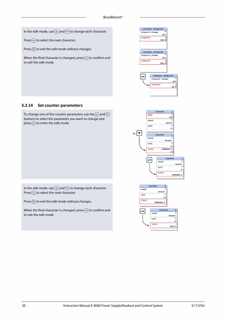
3.2.14 Set counter parameters
To change one of the counter parameters use the and buttons to select the parameter you want to change andpress to enter the edit mode.
In the edit mode, use and to change each character.Press to select the next character.
Press to exit the edit mode without changes.
When the final character is changed, press to confirm andto exit the edit mode.
Bronkhorst®
Instruction Manual E-8000 Power Supply/Readout and Control System9.17.076J 31
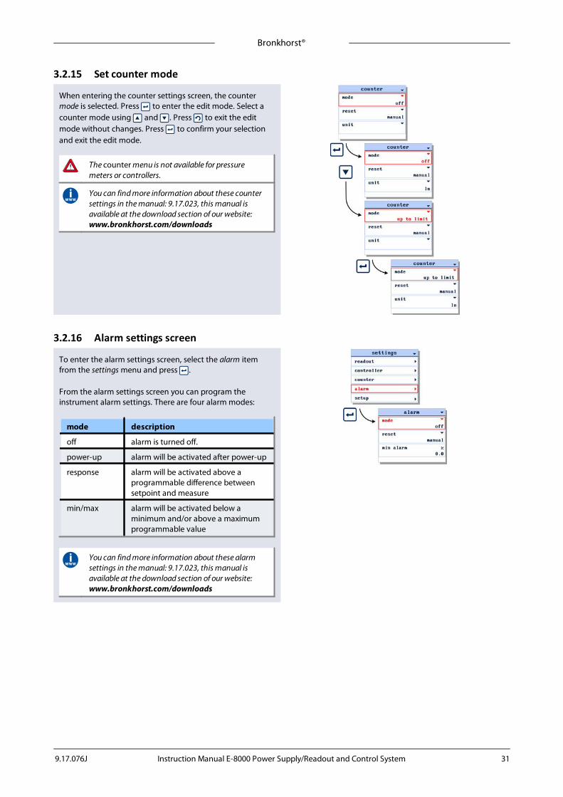
3.2.15 Set counter mode
When entering the counter settings screen, the counter mode is selected. Press to enter the edit mode. Select acounter mode using and . Press to exit the editmode without changes. Press to confirm your selectionand exit the edit mode.
The counter menu is not available for pressuremeters or controllers.
You can find more information about these countersettings in the manual: 9.17.023, this manual isavailable at the download section of our website: www.bronkhorst.com/downloads
3.2.16 Alarm settings screen
To enter the alarm settings screen, select the alarm itemfrom the settings menu and press .
From the alarm settings screen you can program theinstrument alarm settings. There are four alarm modes:
mode description
off alarm is turned off.
power-up alarm will be activated after power-up
response alarm will be activated above aprogrammable difference betweensetpoint and measure
min/max alarm will be activated below aminimum and/or above a maximumprogrammable value
You can find more information about these alarmsettings in the manual: 9.17.023, this manual isavailable at the download section of our website: www.bronkhorst.com/downloads

Bronkhorst®
Instruction Manual E-8000 Power Supply/Readout and Control System 9.17.076J32
3.2.17 Set alarm mode
When entering the alarm settings screen the alarm mode isselected. Press to enter the edit mode. Select an alarmmode using and . Press to confirm your selectionand exit the edit mode.
Press to exit the edit mode without changes.
To change one of the alarm mode parameters use the and buttons to select the parameter you want to changeand press to enter the edit mode.
Press to exit the edit mode without changes.
3.2.18 Set alarm mode parameters
In the edit mode, use and to change each character.
Press to select the next character.
When the final character is changed, press to confirm andto exit the edit mode.
Press to exit the edit mode without changes.

Bronkhorst®
Instruction Manual E-8000 Power Supply/Readout and Control System9.17.076J 33
3.2.19 Set setpoint at alarm
You can program an automatic setpoint which will beactivated when an alarm situation occurs.
To change this alarm setpoint use the button to selectthe setpoint change option and press to enter the alarmsetpoint settings screen.
When entering the alarm setpoint settings screen thesetpoint change parameter is selected. Press to enter theedit mode.
In the edit mode, use and to select 'yes' or 'no'. Press to confirm your selection and to exit the edit mode.
Press to exit the edit mode without changes.
In the alarm setpoint settings screen press to select thesetpoint parameter. Press to enter the edit mode.
In the edit mode, use and to change each character.Press to select the next character.
Press to exit the edit mode without changes.

Bronkhorst®
Instruction Manual E-8000 Power Supply/Readout and Control System 9.17.076J34
When the final character is changed, press to confirm andto exit the edit mode.
3.2.20 Setup menu
To enter the setup screen, select the setup item from thesettings menu and press . Via the setup menu you can:
menu item description
info information about connectedinstrument
customize customize display information
display customize display appearance
communication change communication settingswhen connected to a bus system

Bronkhorst®
Instruction Manual E-8000 Power Supply/Readout and Control System9.17.076J 35
3.2.21 Get instrument information
Select the info item in the setup menu and press . Whenentering the instrument info screen the instrument user tag,serial number and model are displayed.
In the instrument info menu you can find the following items.
parameter editable
usertag yes
instrument serial number no
instrument model number no
instrument firmware version no
operator firmware version no
The ‚ or • signs in the upper right corner indicates that notall the menu items fit in the display and that you need toscroll through the menu using the and buttons toview the hidden menu items. Press to enter the selectedmenu item.
Use the button to return to the measure readout screen.
3.2.22 Change user tag
When entering the instrument info screen the usertagparameter is selected. Press to enter the edit mode.
In the edit mode, use and to change each character.Press to select the next character.
Press to exit the edit mode without changes.
When the final character is changed, press until thecursor disappears to confirm and to exit the edit mode.

Bronkhorst®
Instruction Manual E-8000 Power Supply/Readout and Control System 9.17.076J36
3.2.23 Customize display info
To customize the display information, select the customizeoption in the setup menu and press . In the customize menu you can change:
item description
info top Info in 'Top line' of readout screen(user tag or serial number.)
info bottom Info in 'Custom readout 1'.
setpoint Setpoint edit mode, cursor or steps.
read digits Number of readout digits.
3.2.24 Display appearance
To customize the display appearance, select the display itemin the setup menu and press . In the customize menu youcan change:
item description default
brightness set display brightness: 0...9 7
screensaver
screen saver type: dimmer/off off
saver time time before screen saverbecomes active
1 min.
Deactivate screen saver by pressing any of the fourbuttons one time. This will have no effect on themenu status.
3.3 Communication settings
This display shows information about the communication. The communication display is divided into two sections:· operator· instrument (bus 2 and/or bus 1)

Bronkhorst®
Instruction Manual E-8000 Power Supply/Readout and Control System9.17.076J 37
3.3.1 OperatorChange operator node address
When the operator has the same node address as the existing system, or has a FLOW-BUS node address conflict, youcan change the operator node address.
From the setup menu select the communication item andpress to enter the communication screen.Press to enter the operator screen. Press 2x to move tothe operator node item. Press to enter the edit mode.In the edit mode, use the up and down to change theoperator node address. When required operator node address is visible, press toconfirm. During the edit mode you can press escape to exit theedit mode without changes.
Each operator must have a unique node address, else you get a FLOW-BUS node address conflict.
Select instrument node address
In the operator screen you can select a rear module node address or instrument node address (preset), even whenthere is no connection with the FLOW-BUS system.
From the setup menu select the communication item andpress to enter the communication screen.Press to enter the operator screen. Press 1x to move tothe instr node item. Then press to enter the edit mode.In the edit mode, use the up and down to change andenter to confirm the instrument node address. When the required instrument node address is available,press to confirm. After the conformation the instrument is blinking a shorttime red and green, so you can see which instrument isselected.During the edit mode you can press escape to exit theedit mode without savings.
Each instrument must have a unique node address, else you get a FLOW-BUS node address conflict.
Bronkhorst®
Instruction Manual E-8000 Power Supply/Readout and Control System 9.17.076J38
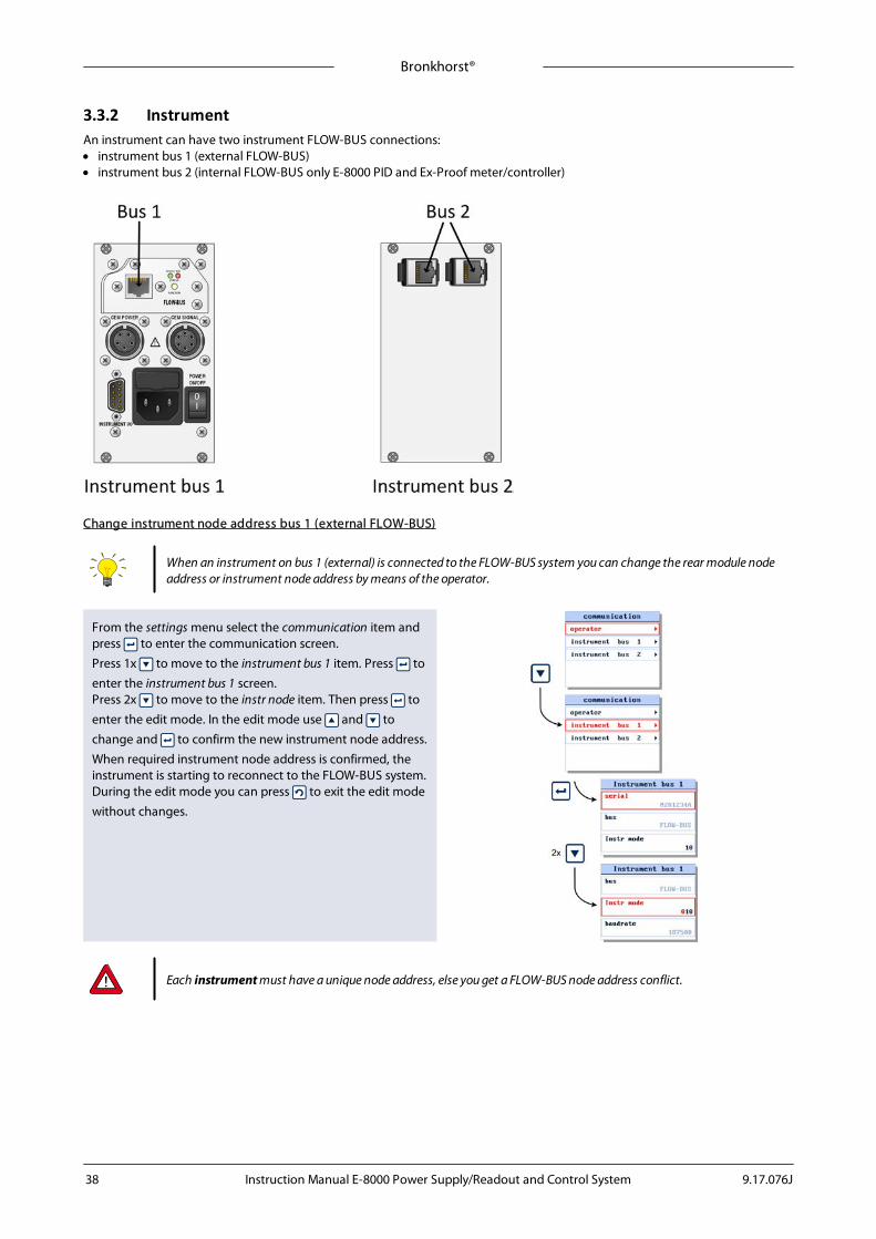
3.3.2 InstrumentAn instrument can have two instrument FLOW-BUS connections: · instrument bus 1 (external FLOW-BUS)· instrument bus 2 (internal FLOW-BUS only E-8000 PID and Ex-Proof meter/controller)
Change instrument node address bus 1 (external FLOW-BUS)
When an instrument on bus 1 (external) is connected to the FLOW-BUS system you can change the rear module nodeaddress or instrument node address by means of the operator.
From the settings menu select the communication item andpress to enter the communication screen.Press 1x to move to the instrument bus 1 item. Press toenter the instrument bus 1 screen.Press 2x to move to the instr node item. Then press toenter the edit mode. In the edit mode use and tochange and to confirm the new instrument node address.When required instrument node address is confirmed, theinstrument is starting to reconnect to the FLOW-BUS system.During the edit mode you can press to exit the edit modewithout changes.
Each instrument must have a unique node address, else you get a FLOW-BUS node address conflict.

Bronkhorst®
Instruction Manual E-8000 Power Supply/Readout and Control System9.17.076J 39
Change instrument node address bus 2 (internal FLOW-BUS only E-8000 PID and Ex-Proof meter/controller)
When an instrument on bus 2 (internal) is connected to the FLOW-BUS system you can change the rear module nodeaddress or instrument node address by means of the operator.
From the setup menu select the communication item andpress to enter the communication screen.Press 2x to move to the instrument bus 2 item. Press toenter the instrument bus 2 screen.Press 2x to move to the instr node item. Then press toenter the edit mode. In the edit mode use and tochange and to confirm the new instrument node address.When required instrument node address is confirmed, theinstrument is starting to reconnect to the FLOW-BUS system.During the edit mode you can press to exit the edit modewithout changes.
Each instrument must have a unique node address, else you get a FLOW-BUS node address conflict.
3.4 Advanced settings
3.4.1 Advanced menu
To enter the advanced settings menu, select advanced in thesettings menu and press . In the advanced settings menuyou can:
menu item description
sensor change sensor filter settings
auto zero start sensor auto zero procedure
restore start restore instrument data procedure
The advanced menu is disabled by default. Refer tosection 3.5 - Security settings for enabling orpassword protect this menu item.

Bronkhorst®
Instruction Manual E-8000 Power Supply/Readout and Control System 9.17.076J40
3.4.2 Sensor filter settings
To change the sensor filter settings select sensor from theadvanced settings menu and press to enter the sensorsettings screen.
The sensor filter is split into a dynamic and a static part. Usethe and button to select the dynamic or staticparameter and press to enter the edit mode.
In the edit mode, use and to change each character.Press to select the next character.
When the final character is changed, press to confirm andto exit the edit mode.
Press to exit the edit mode without changes.
3.4.3 Restore instrument settings
To start the instrument restore procedure, select the instrrestore item from the advanced settings menu and press to enter.
Press to select the start restore option.
Press to start the instrument restore procedure.
While the restore procedure is active, the E-8000 will showthe message ‘BUSY’. When finished it will show ‘restoreready!’.
Press any button to return to settings menu.

Bronkhorst®
Instruction Manual E-8000 Power Supply/Readout and Control System9.17.076J 41
3.4.4 Sensor auto zero
To start the sensor auto zero procedure, select sensor autozero from the advanced settings menu and press to enter.
Press to select the start auto zero option.
Press to start the sensor auto zero procedure.
While the auto zero procedure is active, the E-8000 will showthe message ‘... BUSY ...’. When finished, ‘auto zerosuccessful!’.
Press any key to return to settings menu.

Bronkhorst®
Instruction Manual E-8000 Power Supply/Readout and Control System 9.17.076J42
3.5 Security settings
3.5.1 Security modes
The security settings screen allows you to define the accessof the crucial menu items of the E-8000. For every item, youcan choose the following access modes:
item accessibility
enable Item is accessible without any restrictions
password item is accessible after entering a password
disable Item is not accessible
3.5.2 Enter the security settings screen
From the readout screen press both and for 5 secondstill the enter password display appears.
The default password is 'abc'. The password can consist of amaximum of 8 characters. For less characters press till theend of the edit field. Please refer to section 3.5.4 - Changepassword to change or reset the password.
When you enter a wrong password, the message'invalid password!' will appear.
3.5.3 Security items
The security settings screen allows you to define the accessof the crucial menu items of the E-8000. For every item, youcan choose for enable, disable or password. These settingscan be assigned to the following items.
item accessibility
edit setpoint edit mode of the setpoint in both'Custom readout 1 and 2'.
reset counter counter reset functionality in 'Customreadout 2'.
reset alarm alarm reset functionality displayed in'Custom readout 2'.
selectinstrument
select another instrument on the bussystem displayed in 'Custom readout 2'.
settingsmenu
settings menu.
advanced 'advanced' menu item in the settingsmenu.
Check section 3.5.2 - Enter the security settings screen howto access this settings screen.

Bronkhorst®
Instruction Manual E-8000 Power Supply/Readout and Control System9.17.076J 43
3.5.4 Change password
To change the password, select the new password item andpress .
In the new password input screen press to activate thenew password edit mode.
You can enter a maximum of 8 characters. For lesscharacters, press till the end of the edit field.
After changing the password press to select the confirmitem. Then press .
Now the new password is stored and should be used toenter the password protected items.
Press any key to return to security settings screen.
3.5.5 Reset password
From the readout screen press both and for 5 secondstill the enter password display appears.
Again press both and for 5 seconds till the resetpassword display appears.
The reset password display will show a 10 character long 'bhtkey'. This is your encrypted password. Send this key to yourlocal agency and they will send you, after validation of yourrequest, a reset key. Enter this 10 character reset key in the reset key field. The password will now be reset to its defaultvalue. Press any key to return to the readout screen.
To avoid unauthorized access change the defaultpassword. Check section 3.5.4 - Change password.
If you enter the wrong key, the message 'invalid resetkey!' will appear. Check the key and try again.
Press any key to return to the readout screen.

Bronkhorst®
Instruction Manual E-8000 Power Supply/Readout and Control System 9.17.076J44
4 Modules
4.1 Power supplyEach E-8000 power supply housing incorporates two power supply connectors. System setup is such that the instruments thatbelong to the system can be powered. For other applications or modifications your supplier should be consulted. The powerinput incorporates an on/off switch and a fuse.
4.1.1 Model key power supply
4.1.2 Electrical connectionBelow you find an example of a blind power supply for two (PROFIBUS) Mass Flow Controllers. The model key for this example is E-8501-0-0A.
Bronkhorst®
Instruction Manual E-8000 Power Supply/Readout and Control System9.17.076J 45
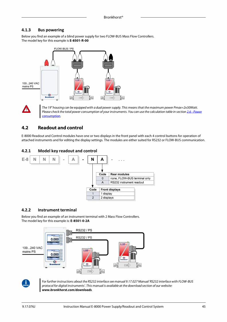
4.1.3 Bus poweringBelow you find an example of a blind power supply for two FLOW-BUS Mass Flow Controllers. The model key for this example is E-8501-R-00
The 19" housing can be equipped with a dual power supply. This means that the maximum power Pmax=2x30Watt.Please check the total power consumption of your instruments. You can use the calculation table in section 2.6 - Powerconsumption.
4.2 Readout and controlE-8000 Readout and Control modules have one or two displays in the front panel with each 4 control buttons for operation ofattached instruments and for editing the display settings. The modules are either suited for RS232 or FLOW-BUS communication.
4.2.1 Model key readout and control
4.2.2 Instrument terminalBelow you find an example of an instrument terminal with 2 Mass Flow Controllers. The model key for this example is: E-8501-0-2A
For further instructions about the RS232 interface see manual 9.17.027 Manual 'RS232 interface with FLOW-BUSprotocol for digital instruments'. This manual is available at the download section of our website: www.bronkhorst.com/downloads.

Bronkhorst®
Instruction Manual E-8000 Power Supply/Readout and Control System 9.17.076J46
4.2.3 FLOW-BUS terminalBelow you find an example of a FLOW-BUS setup with 2 Mass Flow Controllers. The model key for this example is: E-8501-R-20
Below you find an example of a FLOW-BUS setup with 6 Mass Flow Meters. The model key for this example is: E-8101-R-20-20-20
For node addressing and further instructions about the FLOW-BUS interface see manual 9.17.024 Manual 'FLOW-BUSinterface for digital instruments'. This manual is available at the download section of our website: www.bronkhorst.com/downloads.

Bronkhorst®
Instruction Manual E-8000 Power Supply/Readout and Control System9.17.076J 47
4.3 CEM controllerE-8000 CEM controller for Controlled Evaporation and Mixing systems are used for temperature control of the heat exchanger ofthe vapor control device. The temperature can be set using the push buttons on the front panel or by means of an externalanalog setpoint signal. As an option the temperature can be monitored and adjusted via an integrated fieldbus interface.
4.3.1 Model key CEM controller

Bronkhorst®
Instruction Manual E-8000 Power Supply/Readout and Control System 9.17.076J48
4.3.2 Fieldbus options for CEM controllerThe basic analog version of the CEM controller has a 9-pin D-socket at the rear panel for input/output of the temperature of theheat exchanger. Optionally the modules can be equipped with an interface board for digital communication. See the picturebelow for the available options.
Rear panel CEM controller Fieldbus options
The fieldbus connection on the CEM controller cannot be used to power any instruments connected to the bus.
Consult the fieldbus specific manual for fieldbus address and baud rate configuration options.
4.3.3 Electrical connection for CEM controllerBelow you find an example of a CEM controller-system based on PROFIBUS DP communication with 2 Mass Flow Controllers. The model key for this E-8000 with display example is: E-8503-P-1WATU

Bronkhorst®
Instruction Manual E-8000 Power Supply/Readout and Control System9.17.076J 49
4.3.4 Rear panel connection for CEM controller1. Powering for CEM W-101A / W-102A / W-202A
The "CEM power and signal" connector is a 44VAC power outlet. Use a standard Bronkhorst® cable 7.03.218 forconnecting the CEM W-101A, W-102A and the W-202A to the heater. The symbol on the rear panel of the E-8000indicates the location of the power outlet.
2. Powering for CEM W-303B
The "CEM power" connector is a mains power outlet. Use a standard Bronkhorst® cable 7.03.583 for connecting the CEMW-303B, W-102A and the W-202A to the heater. The symbol on the rear panel of the E-8000 indicates the locationof the power outlet.

Bronkhorst®
Instruction Manual E-8000 Power Supply/Readout and Control System 9.17.076J50
4.3.5 Electrical properties for CEM controller
Art. No. Module Rear Type
Label Information
PowerSupply Power max. Fuse mains/primary
Fusesecondar
y
Tmax
4.08.242 E-8005-x-xWxxU/3 110…120V 200VA 50…60Hz T2A I2t >30ALittelfuse 0213002.MXP or equivalent
T4A 40°C
4.08.243 E-8003-x-xWxxU/3 220…240V 200VA 50-60Hz T1A I2t >10ALittelfuse 0213001.MXP or equivalent
T4A 40°C
4.08.245 E-8003-x-xWxxV/3 220…240V 1650VA 50-60Hz T10A - 40°C
4.08.248 E-8005-x-xWxxU/0 110…120V 200VA 50-60Hz T2A I2t >30ALittelfuse 0213002.MXP or equivalent
T4A 40°C
4.08.249 E-8003-x-xWxxU/0 220…240V 200VA 50-60Hz T1A I2t >10ALittelfuse 0213001.MXP or equivalent
T4A 40°C
4.08.251 E-8003-x-xWxxV/0 220…240V 1650VA 50-60Hz T10A - 40°C
4.3.6 Instrument I/O connection for CEM controllerConnection to remote equipment, I/OThe male I/O (sub-miniature 9-pin) D-connector has the following pin configuration:
Pin number Description
1 RS485(B)
2 analog output
3 analog input
4 0V power
5 + actuator out / special
6 RS485(A)
7 not connected
8 0V sense
9 shield
Male 9-pin connector(view from connection side)
Analog input/output signalsAnalog input signals should be connected to pin 3 (+) and 0V power.Analog output signals are available at pin 2 (+) and 0V power.Signals are according to one of the Bronkhorst®. standards. The model configuration contains a code, describing theinput/output signals.
- Max. load current output (sourcing).- Min. load voltage output- Input load resistance (voltage)- Input load resistance (Current) (sinking)
: 375 Ohm: 10 kOhm: 22K4: 250 Ohm

Bronkhorst®
Instruction Manual E-8000 Power Supply/Readout and Control System9.17.076J 51
4.3.7 Operation of CEM controller moduleUpon connection of the power and signal cables, the CEM controller module is ready to controlthe temperature of the heat exchanger. The temperature range of 0 to 200°C corresponds with 0to 5 V I/O signal (4 to 20 mA for current I/O).
For operation of the user interface we refer to chapter 3 of this manual.
For further instructions about the CEM system see manual 9.17.010 Manual 'CEM Controlled Evaporator and Mixer'.This manual is available at the download section of our website: www.bronkhorst.com/downloads.
Bronkhorst®
Instruction Manual E-8000 Power Supply/Readout and Control System 9.17.076J52
4.4 Ex-Proof modulesThe E-8000 Ex-Proof modules have been designed for powering and signal conversion of intrinsic safe meters. Optionally a valve drive circuit can be incorporated in the system. Depending on the limits of the valve, the output stage for thevalve can also be made intrinsically safe by using an isolating repeater.
Without isolating repeater a valve (XC) with “II 2 G (ATEX group and category) - Ex e mb II T4” (CELENEC) classification can bepowered. With isolating repeater a valve (XB) with ” II 1 G/D (ATEX group and category) - Ex ia IIC T6” (CELENEC) classification can bepowered.
The E-8000 Ex-Proof system standard contains an Ex-Proof module and a power supply module. It is possible to use the Ex-Proof module as a stand-alone unit. In this case the power supply must be provided by the user (+24Vdc ± 10%) via the instrument I/O connector at the rear of the module. Optional the system can be equipped with an integratedfieldbus interface.
Because the intrinsic parts of the Ex-Proof modules are completely protected, this will not affect the safety and performance ofthe Ex-Proof modules.
The E-8000 Ex-Proof module itself is not explosion protected, but is developed to control explosion protected equipment.It must be installed outside the ATEX zone.

Bronkhorst®
Instruction Manual E-8000 Power Supply/Readout and Control System9.17.076J 53
4.4.1 Model key Ex-Proof modules
4.4.2 Intrinsic safe electronic units4.4.2.1 Transmitter supply unit for flow sensorsPower supply for intrinsic safe flow sensor, providing galvanic isolation between input, output and power supply.
Manufacturer : R. Stahl Schaltgeräte GmbHType : ISPac 9160/**-1*-1*
Type of protection : II 3 (1) G Ex nA nC [ia] IIC T4
Certificate no. : DMT 03 ATEX E 010 XUo = 27 VIo = 88 mAPo = 576 mWCo Lo Ci = negligibleLi = negligible
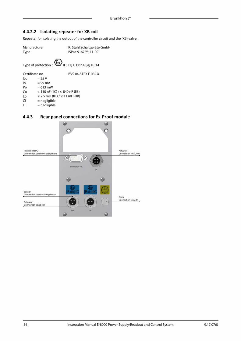
Bronkhorst®
Instruction Manual E-8000 Power Supply/Readout and Control System 9.17.076J54
4.4.2.2 Isolating repeater for XB coilRepeater for isolating the output of the controller circuit and the (XB) valve.
Manufacturer : R. Stahl Schaltgeräte GmbHType : ISPac 9167/**-11-00
Type of protection : II 3 (1) G Ex nA [ia] IIC T4
Certificate no. : BVS 04 ATEX E 082 XUo = 25 VIo = 99 mAPo = 613 mWCo Lo Ci = negligibleLi = negligible
4.4.3 Rear panel connections for Ex-Proof module

Bronkhorst®
Instruction Manual E-8000 Power Supply/Readout and Control System9.17.076J 55
4.4.3.1 Instrument I/OConnection to remote equipment, I/OThe male I/O (sub-miniature 9-pin) D-connector has the following pin configuration:
Pin number Description
1 RS485(B)
2 analog output
3 analog input
4 0V power
5 + actuator out / special
6 RS485(A)
7 not connected / for external +24Vdc power supply
8 0V sense
9 shield
Male 9-pin connector(view from connection side)
Analog input / output signals.Analog input signals should be connected to pin 3 (+) and 0V power.Analog output signals are available at pin 2 (+) and 0V power.Signals are according to one of the Bronkhorst standards. The model configuration contains a code, describing the input/outputsignals.
- Max. load current output (sourcing).- Min. load voltage output- Input load resistance (voltage)- Input load resistance (Current) (sinking)
: 375 Ohm: 10 kOhm: 22K4: 100 Ohm
Power supply (in case of stand-alone)Power supply (+24Vdc ± 10%) must be connected to pin 7 (+) and pin 4 (0V power)
4.4.3.2 Sensor connectionConnection to measuring deviceThe + and - current signal input is intended for loop powered transducers. The 3-pin female connector with bayonet locking hasthe following pin configuration:
Pin number Description
1 + 15 - 20 mA
2 - 15 - 20 mA
3 not connected view from connection side
4.4.3.3 Valve connection XBConnection to XB valveOnly XB type valves may be connected. Consult the label on the module for the correct valve model. The 2-pin female connectorwith bayonet locking has the following pin configuration:
Pin number Description
1 0 valve
2 + valve (0..39 mA)
view from connection side

Bronkhorst®
Instruction Manual E-8000 Power Supply/Readout and Control System 9.17.076J56
4.4.3.4 Valve connection XCConnection to XC valveOnly XC type valves may be connected. Consult the label on the module for the correct valve model. The 4-pin female connectorwith bayonet locking has the following pin configuration:
Pin number Description
1 0 valve
2 + valve (0..200 mA)
view from connection side
In case of valve XC, the module is equipped with an additional 400 mA fuse according IEC 60127-3, to meet the specialconditions for safe use of the applied valve coil.
4.4.4 Fieldbus options for Ex-Proof moduleOptionally the Ex-Proof modules can be equipped with an interface board for digital communication. Communication only for Ex-Proof instrument, no communication possible with other instruments within the network (no masterfunction).See the picture below for the available options.
Rear panel Ex-Proof controller Fieldbus options
The fieldbus connection on the Ex-Proof module cannot be used to power any instruments connected to the bus.
Consult the fieldbus specific manual for fieldbus address and baud rate configuration options.

Bronkhorst®
Instruction Manual E-8000 Power Supply/Readout and Control System9.17.076J 57
4.4.5 Electrical connection for Ex-Proof moduleBelow you find an example of a Ex-Proof controller-system based on PROFIBUS DP communication. The model key for this E-8000 with display example is: E-8500-P-1XAES.
4.4.6 Electrical properties for Ex-Proof moduleGeneral specifications
Specification Range
Operating temperature 0 .. 40°C
Input Power Supply +24 Vdc ± 10%
Placement Outside any ATEX zone
Output for valve with XB-coil (intrinsic safe) 0 .. 39 mA
Output for valve with XC-coil 0 .. 250 mA
Max. Power consumption (excl. display and field bus) MFM 2.6 W
Max. Power consumption (excl. display and field bus) MFM + XB 3.6 W
Max. Power consumption (excl. display and field bus) MFM + XC 8.6 W
4.4.7 Cables4.4.7.1 GeneralAll Bronkhorst® Ex-Proof cables applicable for E-8000 systems comply with the requirements of IEC 60079-14.
4.4.7.2 Cable for sensorFor Ex-Proof applications, cables must comply with the requirements of IEC 60079-14. In case an equivalent cable is used insteadof the standard Bronkhorst® cable, this cable must meet the requirements in the table below.
Bronkhorst recommends using two-wire Lapp Unitronic LiYCY shielded 0,25 mm2 cable or equivalent.
Parameter Description Requirement IEC 60079-14 Lapp Unitronic LiYCY Unit
Ccable capacity cable <200 120 pF/m
Lcable inductivity cable <1 0.65 µH/m
Rcable resistance cable 0.0799 Ù/m
Lcable/Rcable ratio L/R <30 8.14 µH/Ù
The maximum voltage loss (@ 15-20 mA) across the standard Bronkhorst® cable: Uloss = 1.6 mV/m.The maximum allowed cable length for the sensor is 400 meter.
Bronkhorst®
Instruction Manual E-8000 Power Supply/Readout and Control System 9.17.076J58
4.4.7.3 Cable for valve XB/XCThe maximum cable length (Lapp Unitronic LiYCY shielded 0,25 mm2 cable) for the XB/XC-coil is 150 meter.
4.4.8 EMC and instrinsic safe circuitsScreens in cables used for intrinsic safe circuits should be earthed at one point only. For good EMC behavior however, it isessential that the point of earth is chosen according to the setup at which the system was tested. Follow the guidelines for electrical hook-up of sensors (flow) and valves (XC, XB).
4.4.9 Operation of Ex-Proof controller moduleUpon connection of the power and signal cables, the Ex-Proof controller module is ready for read out of the ATEX sensor and /or to control the ATEX XB/XC valve.
For operation of the user interface, refer to section User interface.
For further instructions about ATEX instruments, see manual 9.17.028 ‘Explosion proof Flow measurement and controlATEX’. This manual is available at the download section of our website: www.bronkhorst.com/downloads.
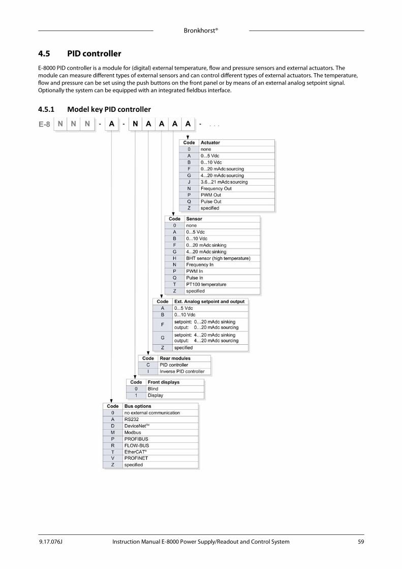
Bronkhorst®
Instruction Manual E-8000 Power Supply/Readout and Control System9.17.076J 59
4.5 PID controllerE-8000 PID controller is a module for (digital) external temperature, flow and pressure sensors and external actuators. Themodule can measure different types of external sensors and can control different types of external actuators. The temperature,flow and pressure can be set using the push buttons on the front panel or by means of an external analog setpoint signal.Optionally the system can be equipped with an integrated fieldbus interface.
4.5.1 Model key PID controller

Bronkhorst®
Instruction Manual E-8000 Power Supply/Readout and Control System 9.17.076J60
4.5.2 Rear panel connections for PID controller
4.5.2.1 Instrument I/O connection for PID controllerConnection to remote equipment, I/OThe male I/O (sub-miniature 9-pin) D-connector has the following pin configuration:
Pin number Description
1 RS485(B)
2 Analog output
3 Analog input
4 0V power
5 + actuator out / special
6 RS485(A)
7 Not connected / for external +24 Vdc power supply
8 0V sense
9 Shield
Male 9-pin connector(view from connection side)
Analog input/output signalsAnalog input signals should be connected to pin 3 (+) and 0V power.Analog output signals are available at pin 2 (+) and 0V power.Signals are according to one of the Bronkhorst®. standards. The model configuration contains a code, describing the input/output signals.
- Max. load current output (sourcing).- Min. load voltage output- Input load resistance (voltage)- Input load resistance (Current) (sinking)
: 375 Ohm: 10 kOhm: 22K4: 100 Ohm
Power supply (in case of stand-alone)Power supply ( +24 Vdc ± 10%) must be connected to pin 7 (+) and pin 4 (0 V power)

Bronkhorst®
Instruction Manual E-8000 Power Supply/Readout and Control System9.17.076J 61
4.5.2.2 Actuator connection for PID controllerConnection to valveThe 4P M8 connector has the following pin configuration:
Pin number Description
1 +Us
2 Special2
3 Valve out (0...250mA)
4 0V power 4-pin M8 connector(view from connection side)
4.5.2.3 Sensor connection for PID controllerConnection to measuring device.The female (sub-miniature 9-pin) D-connector has the following pin configuration:
Pin number Description
1 Digital in
2 Analog in
3 PT100 in
4 0V power
5 PT100 out
6 PT100 sens
7 +Us
8 0V power
9 Shield
Female 9-pin connector(view from connection side)

Bronkhorst®
Instruction Manual E-8000 Power Supply/Readout and Control System 9.17.076J62
4.5.3 Fieldbus options for PID controllerThe basic analog version of the PID controller has a 9-pin D-socket at the rear panel for input/output of thetemperature/flow/pressure and other sensor signals. Optionally the modules can be equipped with an interface board for digitalcommunication. See below picture for the available options.
Rear panel PID controller Fieldbus options
The fieldbus connection on the PID controller cannot be used to power any instruments connected to the bus.
Consult the fieldbus specific manual for fieldbus address and baud rate configuration options.
4.5.4 Electrical connection for PID controllerBelow you find an example of a PID controller-system based on PROFIBUS DP communication with 2 Mass Flow Controllers.The Model key for this E-8000 with display example is: E-8503-P-1CAAA

Bronkhorst®
Instruction Manual E-8000 Power Supply/Readout and Control System9.17.076J 63
4.5.5 How to connect an instrument1. Powering for PID meter
If you connect a sensor to theE-8000 PID you can use the PID for measuring the sensor signal.
2. Powering for PID controller
If you connect a sensor and an actuator to the E-8000 PID you can use the PID to control and measure the flow troughthe sensor.

Bronkhorst®
Instruction Manual E-8000 Power Supply/Readout and Control System 9.17.076J64
4.5.6 Electrical properties for PID controllerGeneral specifications
Specification Range
Operating temperature 0 .. 50°C
Input Power Supply +24 Vdc ± 10%
Output valve 0…250mAdc
Max. power consumption (only sensor 100W) 1W
Max. power consumption (only sensor 100W + valve fully open) 6.5W
Max. power consumption (only sensor 100W + valve fully open + output pin2 20mA + output pin5 20mA + output actuator 20mA)
7.85W
4.5.7 Operation of PID controller moduleUpon connection of the power and signal cables, the PID controller module is ready to controlthe temperature/flow and pressure of the system. The full scale sensor signal corresponds with 0to 5 V I/O signal (4 to 20 mA for current I/O).
For operation of the user interface, refer to section User interface.

Bronkhorst®
Instruction Manual E-8000 Power Supply/Readout and Control System9.17.076J 65
5 Troubleshooting
Symptom Action
Display is not lit after 'power on' · check power supply· check fuse
No reading/control · check instrument cabling· check if instrument is powered-up· for FLOW-BUS systems check node number· for FLOW-BUS systems check cables / termination
Wrong reading format · check module settings (“settings/readout” menu)
Instrument seems to give inaccuratevalues
· check if correct fluid set (with calibration factors) has been selected (see“settings/readout/fluidset”)
· check if correct instrument is selected by the FLOW-BUS
Setpoint is ignored · for meters setpoint facilities are disabled.· setpoint source in menu “settings/controller/mode” menu should be
"bus/rs232". (other settings means different behavior)· setpoint could have been overruled by an alarm situation or counter limit (first
perform reset)· setpoint slope has a large value. (setpoint will slowly change in time) Change
slope value if necessary· setpoint could be changed by other devices connected to the FLOW-BUS· setpoint could be controlled by a master/slave instrument configuration· check communication with FLOW-BUS (if applicable)· Fail Safe State. For PROFIBUS/DeviceNet™/EtherCAT® instruments without bus
communication set the setpoint control mode on RS232
Counter/alarm is not responding toreset
· check if reset-source has been enabled in the “security” menu
Display shows “no connection” · check if the operating instrument is active· check if the operating instrument is still at the same node address· check instrument and module cabling· check the node address at “instrument” in the main menu
Parameter not available · parameter is not supported by the connected instrument
Parameter or menu not accessible · menu or parameter blocked by security mode
Settings menu not accessible or notpresent
· menu blocked by security mode· still in edit or alarm mode in main menu
Other problems · check instrument and operating module parameters
Before switching on power, check if all connections have been made according to the hook-up diagram. The hook-updiagrams are available at the download section of our website: www.bronkhorst.com/downloads.
LED indications can be very useful in case of problems with the instrument. See the “MANUAL INTERFACE: micro-switchand LED’s” section in the manual “Operation instructions digital instruments (document nr. 9.17.023)”. This manual isavailable at the download section of our website: www.bronkhorst.com/downloads.

Bronkhorst®
Instruction Manual E-8000 Power Supply/Readout and Control System 9.17.076J66
6 Removal and return instructionsWhen returning materials, always clearly describe the problem, and, if possible, the work to be done, in a covering letter.
Prepare equipment:1. Switch off power supply2. Disconnect cables3. Insert the device into a plastic bag and seal the bag4. Place the bag in an appropriate shipping container; if possible, use the original packaging box
Add documentation:· Reason of return· Failure symptoms· Declaration on decontamination (if applicable)
A safety information document containing a 'Declaration on decontamination' form (document no 9.17.032) can bedownloaded from the Service & Support section of the Bronkhorst website (www.bronkhorst.com).
Important:Clearly note, on top of the package, the customs clearance number of Bronkhorst High-Tech B.V.:
NL801989978B01
(only if applicable, otherwise contact your distributor for local arrangements.)

Bronkhorst®
Instruction Manual E-8000 Power Supply/Readout and Control System9.17.076J 67
7 ServiceFor current information on Bronkhorst® and service addresses, please visit our website:
http://www.bronkhorst.com
Do you have any questions about our products? Our Sales Department will gladly assist you selecting the right product for yourapplication. Contact sales by e-mail:
For after-sales questions, our Customer Service Department is available with help and guidance.To contact CSD by e-mail:
No matter the time zone, our experts within the Support Group are available to answer your request immediately or ensureappropriate further action. Our experts can be reached at:
+31 859 02 18 66
Bronkhorst High-Tech B.V.Nijverheidsstraat 1ANL-7261 AK RuurloThe Netherlands