instruction manual for three-phase line impedance
TRANSCRIPT

Page 1 of 28
INSTRUCTION MANUAL LI-3P-1x Series 3-PHASE LINE IMPEDANCE STABILIZATION NETWORKS (LISNs)
19121 E l To ro Rd ● S i l verado, Cal i fo rn ia 92676 ● (949) 459-9600 ● com-power .com
REV083017
INSTRUCTION MANUAL for
THREE-PHASE LINE IMPEDANCE STABILIZATION
NETWORKS (LISNs)
Models:
LI-3P-116 (16 Amp)
LI-3P-132 (32 Amp)
LI-3P-163 (63 Amp)
LI-3P-1100 (100 Amp)

Page 2 of 28
INSTRUCTION MANUAL LI-3P-1x Series 3-PHASE LINE IMPEDANCE STABILIZATION NETWORKS (LISNs)
- TABLE OF CONTENTS -
19121 E l To ro Rd ● S i l verado, Cal i fo rn ia 92676 ● (949) 459-9600 ● com-power .com
REV083017
Table of Contents
1.0 Introduction ........................................................................................................... 4
2.0 Products Available from Com-Power ................................................................. 5
3.0 Product Information .............................................................................................. 6 3.1 Incoming Inspection............................................................................................................... 6 3.2 Package Inventory ................................................................................................................. 6 3.3 Product Safety Information.....................................................................................................7
3.3.1 Product Hazard Symbols Definitions.............................................................................. 7 3.3.2 Product Warning/Caution Statements ......................................................................... 7 3.3.3 General Safety Instructions............................................................................................. 8
3.4 Product Features ................................................................................................................... 10 3.5 Product Specifications.......................................................................................................... 12
4.0 LISN Installation.................................................................................................... 14 4.1 LISN Theory............................................................................................................................. 14 4.2 Safety Considerations........................................................................................................... 15 4.3 Test Equipment Setup and Connections ............................................................................. 16
4.3.1 LISN Input Power Connections ..................................................................................... 17 4.3.2 LISN Output Power Connections ................................................................................. 19
5.0 LISN Operation..................................................................................................... 21 5.1 Local (Front Panel) Operation.............................................................................................. 21 5.2 Remote Operation ................................................................................................................ 21 5.3 Fan Operation (LI-3P-163 and LI-3P-1100 models only) .................................................... 22
6.0 LISN Measurements............................................................................................. 23 6.1 LISN Insertion Loss Factors ....................................................................................................23
6.1.1 Example Calculations.................................................................................................... 24 6.1.2 LISN Insertion Loss Calibration....................................................................................... 25 6.1.3 Non-LISN Insertion Loss Calibration .............................................................................. 26
7.0 Warranty............................................................................................................... 27
8.0 Product Maintenance......................................................................................... 28

Page 3 of 28
INSTRUCTION MANUAL LI-3P-1x Series 3-PHASE LINE IMPEDANCE STABILIZATION NETWORKS (LISNs)
- L IST OF F IGURES -
19121 E l To ro Rd ● S i l verado, Cal i fo rn ia 92676 ● (949) 459-9600 ● com-power .com
REV083017
List of Figures
FIGURE 1 - Product Features – Front Panel and Top View 10
FIGURE 2 - Product Features – LISN Rear Panel & RLI-100 11
FIGURE 3 - Product Dimensions 13
FIGURE 4 - Example Schematic of LI-3P-1x Series LISN 14
FIGURE 5 - Example Test Equipment Setup/Connections 16
FIGURE 6 - Wiring Instructions for Power Input Port Socket (16/32 Amp) 17
FIGURE 7 - Wiring Instructions for Power Input Port Socket (63/100 Amp) 18
FIGURE 8 - Wiring Instructions for EUT Power Port Plug (16/32 Amp) 19
FIGURE 9 - Wiring Instructions for EUT Power Port Plug (63/100 Amp) 20
FIGURE 10 - Typical Insertion Loss Factors for LI-3P-1x Series LISNs 23
FIGURE 11 - Setup Diagrams for LISN Insertion Loss Calibration 25
FIGURE 12 - Setup Diagrams for Insertion Loss Calibration 26
Page 4 of 28
INSTRUCTION MANUAL LI-3P-1x Series 3-PHASE LINE IMPEDANCE STABILIZATION NETWORKS (LISNs)
SECTION 1 - INTRODUCTION
19121 E l To ro Rd ● S i l verado, Cal i fo rn ia 92676 ● (949) 459-9600 ● com-power .com
REV083017
1.0 Introduction This manual includes descriptions of front and rear panel ports, controls and indicators; product specifications, safety precautions, operational instructions and warranty information and guidelines and instructions for its proper usage.
Information contained in this manual is the property of Com-Power Corporation. It is issued with the understanding that the material may not be reproduced or copied without the express written permission of Com-Power.

Page 5 of 28
INSTRUCTION MANUAL LI-3P-1x Series 3-PHASE LINE IMPEDANCE STABILIZATION NETWORKS (LISNs)
SECTION 2 - PRODUCTS AVAILABLE FROM COM-POWER
19121 E l To ro Rd ● S i l verado, Cal i fo rn ia 92676 ● (949) 459-9600 ● com-power .com
REV083017
2.0 Products Available from Com-Power
www.com-power.com

Page 6 of 28
INSTRUCTION MANUAL LI-3P-1x Series 3-PHASE LINE IMPEDANCE STABILIZATION NETWORKS (LISNs)
SECTION 3 - PRODUCT INFORMATION
19121 E l To ro Rd ● S i l verado, Cal i fo rn ia 92676 ● (949) 459-9600 ● com-power .com
REV083017
3.0 Product Information
3.1 Incoming Inspection WARNING – To avoid possibility of electrical shock, do not apply power to the LISN or any of its accessories if there is any evidence of shipping damage. If shipping damage to the product or any of the accessories is suspected, or if the package contents are not complete, contact Com-Power or your Com-Power distributor.
Please check the contents of the shipment against the package inventory in section 3.2 to ensure that you have received all applicable items.
3.2 Package Inventory STANDARD ITEMS:
LI-3P-1xxx Line Impedance Stabilization Network (LISN) RLI-100 Remote LISN Interface 10-meter Fiber Optic Cable (Duplex Latching POF Connector at each end) AC Power Adapter (6 Volts DC, 500 mA, unregulated)
(for powering the LISN fiber optic interface circuit) AC Power Adapter (6 Volts DC, 500 mA, unregulated)
(for powering the RLI-100 Remote LISN Interface Box) Calibration Certificate and Data AC Power Adapter (15 Volts DC, 500 mA, unregulated)
(for powering The internal LISN cooling fans) - LI-3P-163 and LI-3P-1100 Models only -
OPTIONAL ITEMS: LIT-153A Transient Limiter ATTEN-10-2W 10 dB Attenuator

Page 7 of 28
INSTRUCTION MANUAL LI-3P-1x Series 3-PHASE LINE IMPEDANCE STABILIZATION NETWORKS (LISNs)
SECTION 3 - PRODUCT INFORMATION
19121 E l To ro Rd ● S i l verado, Cal i fo rn ia 92676 ● (949) 459-9600 ● com-power .com
REV083017
3.3 Product Safety Information
3.3.1 Product Hazard Symbols Definitions The hazard symbols appearing on the product exterior are defined below.
The yellow triangle with an exclamation mark indicates the presence of important operating and/or maintenance (servicing) instructions in the literature accompanying the product.
The yellow triangle with a lightning bolt indicates an alert to the user that uninsulated dangerous voltages are present within the product enclosure and on output connectors. These voltages may be of sufficient magnitude to constitute a risk of electric shock to persons.
The Ground symbol inside a circle indicates terminal which is intended for connection to an external conductor for protection against electric shock in case of a fault, or the terminal of a protective earth (ground) electrode.
To indicate on the rating plate that the equipment is suitable for AC current.
To indicate on the rating plate that the equipment is suitable for direct current.
3.3.2 Product Warning/Caution Statements The following warnings/caution statements must be adhered to in order to ensure safe operation of the product.
WARNING: HIGH VOLTAGE! CONNECT PROTECTIVE EARTH BEFORE APPLYING POWER! VERIFY INPUT POWER CONFIGURATION PRIOR TO MAKING CONNECTION.
CAUTION: TO PREVENT ELECTRIC SHOCK, DO NOT OPEN COVER. CONNECT PROTECTIVE EARTH BEFORE APPLYING POWER. NO USER SERVICEABLE PARTS INSIDE. REFER SERVICING TO QUALIFIED PERSONNEL ONLY. TO AVOID OVERHEATING, OPERATE FANS DURING USAGE. (applies only to LI-3P-163 and LI-3P-1100)

Page 8 of 28
INSTRUCTION MANUAL LI-3P-1x Series 3-PHASE LINE IMPEDANCE STABILIZATION NETWORKS (LISNs)
SECTION 3 - PRODUCT INFORMATION
19121 E l To ro Rd ● S i l verado, Cal i fo rn ia 92676 ● (949) 459-9600 ● com-power .com
REV083017
3.3.3 General Safety Instructions The following safety instructions have been included in compliance with safety standard regulations. Please read them carefully.
• READ AND RETAIN INSTRUCTIONS - Read all safety and operating instructions before operating the instrument. Retain all instructions for future reference.
• HEED WARNINGS - Adhere to all warnings on the instrument and operating instructions.
• FOLLOW INSTRUCTIONS - Follow all operating and use instructions. • WATER AND MOISTURE - Do not use the instrument near water. • VENTILATION - The instrument should be used/installed only in locations
where the flow of air through the ventilation openings is not impeded. • MOUNTING – The instrument can be used in Horizontal or vertical
orientation as long as the ventilation holes are not obstructed and the protective grounding is not defeated.
• HEAT - The instrument should be situated away from heat sources such as heat registers or other instruments which produce heat.
• POWER SOURCES - Connect the instrument only to the type of power source described in the operating instructions or as marked on the instrument.
• GROUNDING - Take precautions to insure that the grounding of the instrument is not defeated. Grounding conductor with adequate cross-section must be connected between a grounding conductor connection for the measurement area and the grounding conductor connection (grounding bolt) on the back panel of the LISN and the LISN bottom plate, before applying any power to the LISN. At shutdown or before dismantling the LISN setup, ensure that the power to LISN is discontinued before the ground conductor connection is disconnected.
• CAUTION - The specified minimum line to ground capacitance induces leakage currents in excess of the value permitted under EN 61010-1 standard – safety requirements for electrical equipment for measurement, control and laboratory use. In addition, the basic insulation required for a category I protection device cannot be assured. Therefore it is imperative to provide additional measures safeguarding against direct or indirect contact by user. The operator is responsible for ensuring that protection is maintained during work with the line impedance stabilization network (LISN). Before using the LISN, a secure ground connection must be made to the LISN grounding bolt and/or the bottom metal plate (The bottom surface of the LISN is left unpainted for effective ground connection). It must not be removed until after the LISN has been disconnected from the mains power supply, in order to avoid electric shock. The safety notes in the accompanying operating instructions and on the outside of the device must be followed at all times.

Page 9 of 28
INSTRUCTION MANUAL LI-3P-1x Series 3-PHASE LINE IMPEDANCE STABILIZATION NETWORKS (LISNs)
SECTION 3 - PRODUCT INFORMATION
19121 E l To ro Rd ● S i l verado, Cal i fo rn ia 92676 ● (949) 459-9600 ● com-power .com
REV083017
• POWER CORD PROTECTION - Place power supply cords so that they are
not likely to be walked on or pinched by items placed on them or against them.
• CLEANING – Clean the instrument outside surfaces of the device with a soft, lint-free cloth. If necessary, a mild detergent may be used.
• NON-USE PERIODS - Unplug the power cords of the instrument when it will be left unused for a long period of time.
• OBJECT AND LIQUID ENTRY - Take care that objects do not fall into the instruments and that liquids are not spilled into the enclosure through openings.
• DEFECTS AND ABNORMAL STRESS - Whenever it is likely that the normal operation has been impaired, make the equipment inoperable and secure it against further operation.
• SITTING OR CLIMBING - Do not sit or climb upon the instrument or use it as a step or ladder.
• ENVIRONMENTAL CONDITIONS - This equipment is designed for indoor use. Ambient temperature range during operation should be between 5° C to 40° C.
• STORAGE AND PACKAGING - The device should only be stored at a temperature between –25 and +70 °C. During extended periods of storage, protect the device from dust accumulation. The original packaging should be used if the device is transported or shipped again. If the original packaging is no longer available, the device should be packed carefully to prevent mechanical damage.
Page 10 of 28
INSTRUCTION MANUAL LI-3P-1x Series 3-PHASE LINE IMPEDANCE STABILIZATION NETWORKS (LISNs)
SECTION 3 - PRODUCT INFORMATION
19121 E l To ro Rd ● S i l verado, Cal i fo rn ia 92676 ● (949) 459-9600 ● com-power .com
REV083017
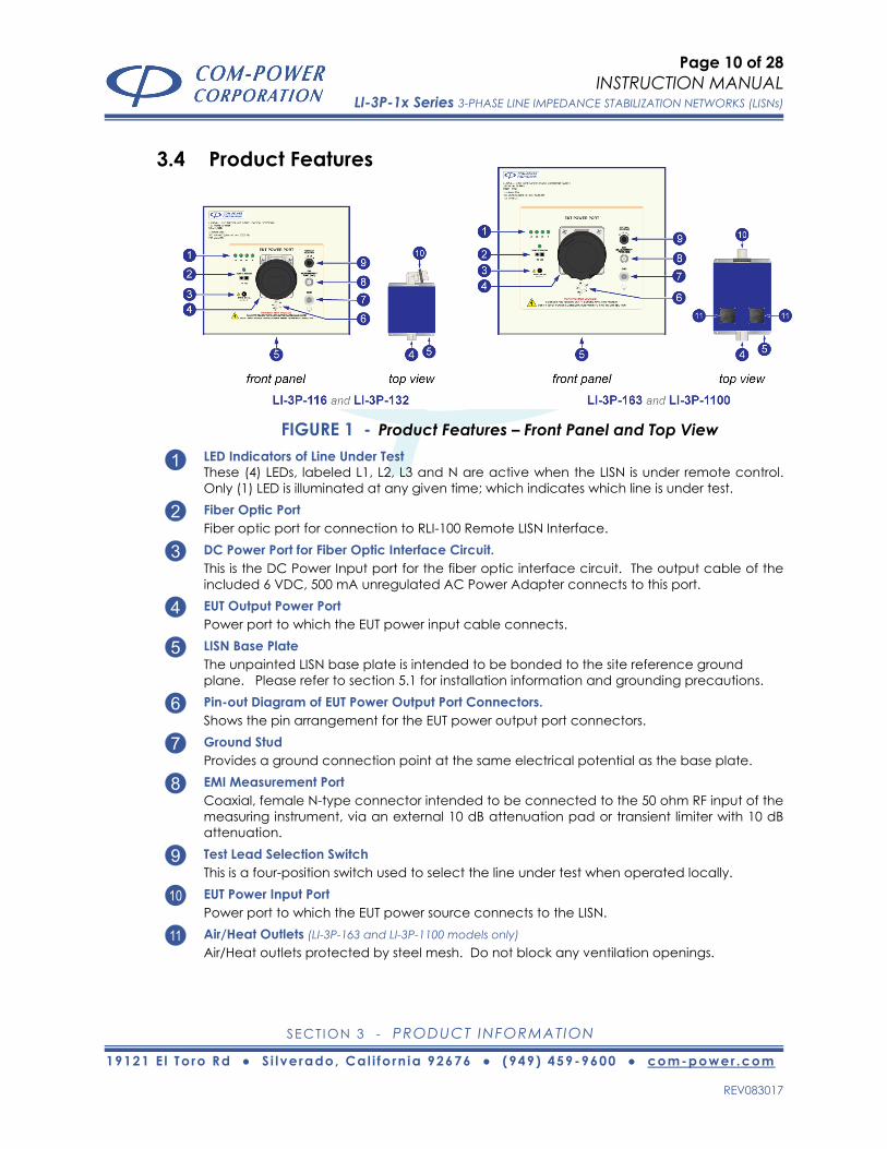
3.4 Product Features
FIGURE 1 - Product Features – Front Panel and Top View LED Indicators of Line Under Test 1 These (4) LEDs, labeled L1, L2, L3 and N are active when the LISN is under remote control. Only (1) LED is illuminated at any given time; which indicates which line is under test. Fiber Optic Port 2 Fiber optic port for connection to RLI-100 Remote LISN Interface. DC Power Port for Fiber Optic Interface Circuit. 3 This is the DC Power Input port for the fiber optic interface circuit. The output cable of the included 6 VDC, 500 mA unregulated AC Power Adapter connects to this port. EUT Output Power Port 4 Power port to which the EUT power input cable connects. LISN Base Plate 5 The unpainted LISN base plate is intended to be bonded to the site reference ground plane. Please refer to section 5.1 for installation information and grounding precautions. Pin-out Diagram of EUT Power Output Port Connectors. 6 Shows the pin arrangement for the EUT power output port connectors. Ground Stud 7 Provides a ground connection point at the same electrical potential as the base plate. EMI Measurement Port 8 Coaxial, female N-type connector intended to be connected to the 50 ohm RF input of the measuring instrument, via an external 10 dB attenuation pad or transient limiter with 10 dB attenuation. Test Lead Selection Switch 9 This is a four-position switch used to select the line under test when operated locally. EUT Power Input Port 10 Power port to which the EUT power source connects to the LISN. Air/Heat Outlets (LI-3P-163 and LI-3P-1100 models only) 11 Air/Heat outlets protected by steel mesh. Do not block any ventilation openings.

Page 11 of 28
INSTRUCTION MANUAL LI-3P-1x Series 3-PHASE LINE IMPEDANCE STABILIZATION NETWORKS (LISNs)
SECTION 3 - PRODUCT INFORMATION
19121 E l To ro Rd ● S i l verado, Cal i fo rn ia 92676 ● (949) 459-9600 ● com-power .com
REV083017
FIGURE 2 - Product Features – LISN Rear Panel & RLI-100
EUT Power Input Port 12 Power port to which the EUT power source connects to the LISN. Ground Stud 13 Provides a ground connection point at the same electrical potential as the base plate. Fan Intake (LI-3P-163 and LI-3P-1100 models only) 14 4.5” circular fan intake openings protected by metal finger guards. Power Switch for Internal Fans (LI-3P-163 and LI-3P-1100 models only) 15 Turns ON/OFF internal cooling fans. Fuse Mounting Assembly (LI-3P-163 and LI-3P-1100 models only) 16 Provides access to input power fuse. (T) type fuse, 250V, 500 mA. DC Power Port for Internal Fans (LI-3P-163 and LI-3P-1100 models only) 17 This is the DC Power Input port for the internal cooling fans. The output cable of the included 15 VDC, 500 mA unregulated AC Power Adapter connects to this port. USB Button 18 Pressing the USB button allows a connected computer to control which line is selected; this feature is currently not supported.. USB LED Indicator 19 Indicates that the USB button is pressed, and computer control is enabled; this feature is currently not supported. LED Indicators of Line Under Test 20 These (4) LEDs correspond to the button immediately below each indicator. The LED which is lit indicates the current line under test. Line Under Test Selection Buttons 21 These (4) buttons are used to select the Line Under Test. USB Port 22 This USB port is for computer connection, and is currently not supported. DC Power Port 23 This is the DC Power Input port for the RLI-100. The output cable of the included 6 VDC, 500 mA unregulated AC Power Adapter connects to this port. Fiber Optic Port 24 Fiber optic port for connection to LISN.

Page 12 of 28
INSTRUCTION MANUAL LI-3P-1x Series 3-PHASE LINE IMPEDANCE STABILIZATION NETWORKS (LISNs)
SECTION 3 - PRODUCT INFORMATION
19121 E l To ro Rd ● S i l verado, Cal i fo rn ia 92676 ● (949) 459-9600 ● com-power .com
REV083017
3.5 Product Specifications
Typical Impedance Data Typical Phase Data
0
10
20
30
40
50
60
70
80
0.1 1 10 100Frequency (MHz)
Impe
danc
e (Ω
)
CISPR 16-1-2 and ANSI C63.4
-20
-10
0
10
20
30
40
50
60
70
80
0.1 1 10 100Frequency (MHz)
Phas
e (d
egre
es)
0
2
4
6
0.1 1 10 100Frequency (MHz)
Inse
rtio
n Lo
ss (
dB)
0
20
40
60
80
1000.1 1 10 100
Frequency (MHz)
Isol
atio
n (d
B)
Typical Insertion Loss Typical Isolation Data
LI-3P-116 LI-3P-132 LI-3P-163 LI-3P-1100GENERAL
Products Description Line Impedance Stabilization Network (LISN)Application Power Line Conducted Emissions Tests
Standards ANSI C63.4, CISPR 16-1-2Type 50Ω / 50 μH, (4) Conductor Network
Frequency Range 150 kHz to 30 MHzInsertion Loss (Voltage Division Factor) <0.7 dB
Isolation >40 dBINPUT POWER RATINGS FOR EQUIPMENT UNDER TEST (EUT)
Current (maximum continuous, per line) 16 Amperes 32 Amperes 63 Amperes 100 AmperesAC Voltage (maximum) 500 Voltsrms (line to line), 288 Voltsrms (line to ground)DC Voltage (maximum) 705 Volts DC
ELECTRICALRemote Interface Power Inputs 6 Volts DC (unregulated), 500 mA (LISN and RLI-100 Remote LISN Interface)
Cooling Fans Power Input Not Applicable 15 Volts DC (unregulated), 500 mAINPUT/OUTPUT CONNECTORS
Power Input Port Plug Schneider ElectricP/N: 83862
Schneider ElectricP/N: 83874
Schneider ElectricP/N: 81886
Schneider ElectricP/N: 81898
Power Input Socket(for power input cable)
Schneider ElectricP/N: PKF16M745
Schneider ElectricP/N: PKF32M745
Schneider ElectricP/N: 81486
Schneider ElectricP/N: 81498
Power Output Port Socket Schneider ElectricP/N: PKF16F745
Schneider ElectricP/N: PKF32F745
Schneider ElectricP/N: 81286
Schneider ElectricP/N: 81298
Power Output Port Plug(for EUT power cable)
Schneider ElectricP/N: PKE16M745
Schneider ElectricP/N: PKE32M745
Schneider ElectricP/N: 81386
Schneider ElectricP/N: 81398
RF Measurement Port 50Ω - N-Type (female)Fiber Optic Ports Avago Duplex Latching POF Jack (LISN and RLI-100 Remote LISN Interface)
Remote Interface Power Input Ports 5.5/2.5 mm Power Jack (LISN and RLI-100 Remote LISN Interface)Cooling Fans Power Input Port Not Applicable 5.5/2.1 mm Power Jack
-- --
Page 13 of 28
INSTRUCTION MANUAL LI-3P-1x Series 3-PHASE LINE IMPEDANCE STABILIZATION NETWORKS (LISNs)
SECTION 3 - PRODUCT INFORMATION
19121 E l To ro Rd ● S i l verado, Cal i fo rn ia 92676 ● (949) 459-9600 ● com-power .com
REV083017
Product Specifications (continued)
All values are typical, unless specified.
All specifications are subject to change without notice.
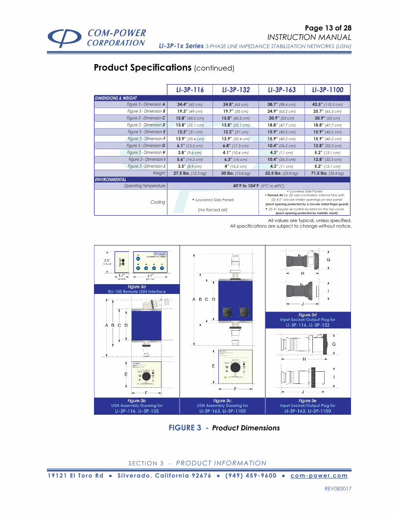
FIGURE 3 - Product Dimensions
LI-3P-116 LI-3P-132 LI-3P-163 LI-3P-1100DIMENSIONS & WEIGHT
Figure 3 - Dimension A 24.4” (62 cm) 24.8” (63 cm) 38.7” (98.4 cm) 43.5” (110.5 cm)
Figure 3 - Dimension B 19.3” (49 cm) 19.7” (50 cm) 24.9” (63.2 cm) 25.7” (65.3 cm)
Figure 3 - Dimension C 15.8” (40.2 cm) 15.8” (40.2 cm) 20.9” (53 cm) 20.9” (53 cm)
Figure 3 - Dimension D 13.8” (35.1 cm) 13.8” (35.1 cm) 18.8” (47.7 cm) 18.8” (47.7 cm)
Figure 3 - Dimension E 12.2” (31 cm) 12.2” (31 cm) 15.9” (40.5 cm) 15.9” (40.5 cm)
Figure 3 - Dimension F 13.9” (35.4 cm) 13.9” (35.4 cm) 15.9” (40.5 cm) 15.9” (40.5 cm)
Figure 3 - Dimension G 6.1” (15.5 cm) 6.8” (17.3 cm) 10.4” (26.5 cm) 12.8” (32.5 cm)
Figure 3 - Dimension H 3.8” (9.6 cm) 4.1” (10.4 cm) 4.3” (11 cm) 5.2” (13.1 cm)
Figure 3 - Dimension I 5.6” (14.2 cm) 6.3” (16 cm) 10.4” (26.5 cm) 12.8” (32.5 cm)
Figure 3 - Dimension J 3.5” (8.9 cm) 4” (10.2 cm) 4.3” (11 cm) 5.2” (13.1 cm)
Weight 27.5 lbs. (12.5 kg) 30 lbs. (13.6 kg) 52.5 lbs. (23.8 kg) 71.5 lbs. (32.4 kg)
ENVIRONMENTALOperating Temperature 40°F to 104°F (5°C to 40°C)
Cooling • Louvered Side Panels
(no forced air)
• Louvered Side Panels• Forced Air by (2) user-controlled, internal fans with
(2) 4.5” circular intake openings on rear panel
• (2) 4” square air outlets located on the top cover (each opening protected by metallic mesh)
Page 14 of 28
INSTRUCTION MANUAL LI-3P-1x Series 3-PHASE LINE IMPEDANCE STABILIZATION NETWORKS (LISNs)
SECTION 4 - PRODUCT APPLICATION
19121 E l To ro Rd ● S i l verado, Cal i fo rn ia 92676 ● (949) 459-9600 ● com-power .com
REV083017
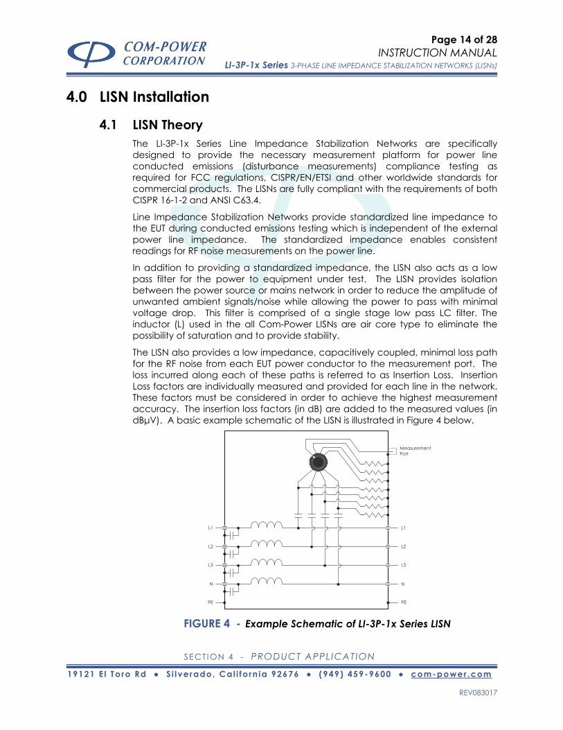
4.0 LISN Installation
4.1 LISN Theory The LI-3P-1x Series Line Impedance Stabilization Networks are specifically designed to provide the necessary measurement platform for power line conducted emissions (disturbance measurements) compliance testing as required for FCC regulations, CISPR/EN/ETSI and other worldwide standards for commercial products. The LISNs are fully compliant with the requirements of both CISPR 16-1-2 and ANSI C63.4.
Line Impedance Stabilization Networks provide standardized line impedance to the EUT during conducted emissions testing which is independent of the external power line impedance. The standardized impedance enables consistent readings for RF noise measurements on the power line.
In addition to providing a standardized impedance, the LISN also acts as a low pass filter for the power to equipment under test. The LISN provides isolation between the power source or mains network in order to reduce the amplitude of unwanted ambient signals/noise while allowing the power to pass with minimal voltage drop. This filter is comprised of a single stage low pass LC filter. The inductor (L) used in the all Com-Power LISNs are air core type to eliminate the possibility of saturation and to provide stability.
The LISN also provides a low impedance, capacitively coupled, minimal loss path for the RF noise from each EUT power conductor to the measurement port. The loss incurred along each of these paths is referred to as Insertion Loss. Insertion Loss factors are individually measured and provided for each line in the network. These factors must be considered in order to achieve the highest measurement accuracy. The insertion loss factors (in dB) are added to the measured values (in dBμV). A basic example schematic of the LISN is illustrated in Figure 4 below.
FIGURE 4 - Example Schematic of LI-3P-1x Series LISN
L1
L2
L3
N
MeasurementPort
L1
L2
L3
N
PE PE

Page 15 of 28
INSTRUCTION MANUAL LI-3P-1x Series 3-PHASE LINE IMPEDANCE STABILIZATION NETWORKS (LISNs)
SECTION 4 - PRODUCT APPLICATION
19121 E l To ro Rd ● S i l verado, Cal i fo rn ia 92676 ● (949) 459-9600 ● com-power .com
REV083017
4.2 Safety Considerations It is critical that the LISN be installed in a manner which ensures that EACH of following conditions are satisfied:
• The metal enclosure of the LISN must be connected to the reference ground plane of the site. The recommended connection method is via a direct, surface to surface connection between the LISN base plate and an exposed, conductive surface of the floor or wall of a shielded enclosure. The LISN base plate should be bolted to the surface using the mounting holes on the front and back of the LISN base plate.
Where installation as described in the previous paragraph is not possible, the LISN may be connected to earth ground via the ground lug located on the rear panel of the LISN. Thick metallic braid or heavy gauge wiring is recommended, and the length shall be kept as short as possible.
In cases where no ground plane is available, a mains isolating transformer shall be used.
Please refer to the safety instructions in section 3.3 for more information on the importance of grounding. The grounding instructions are to be followed at all times.
• The ventilation openings in the LISN enclosure must be unobstructed.
• No signal or operating voltages/currents shall exceed those specified in the product specifications listed in section 3.5.
• The LISN power input port must connected to an appropriate power source protected by a circuit breaker with a current rating which is greater than or equal to the rating of the LISN.
Due to the high level of earth leakage current, the device cannot be connected to any power source protected by a Ground Fault Circuit Interrupter (GFCI), also called Ground Fault Interrupter (GFI) or Residual Current Device (RCD).
Failure to comply with any of these points may damage the equipment and/or pose an electrical hazard.
Page 16 of 28
INSTRUCTION MANUAL LI-3P-1x Series 3-PHASE LINE IMPEDANCE STABILIZATION NETWORKS (LISNs)
SECTION 4 - PRODUCT APPLICATION
19121 E l To ro Rd ● S i l verado, Cal i fo rn ia 92676 ● (949) 459-9600 ● com-power .com
REV083017
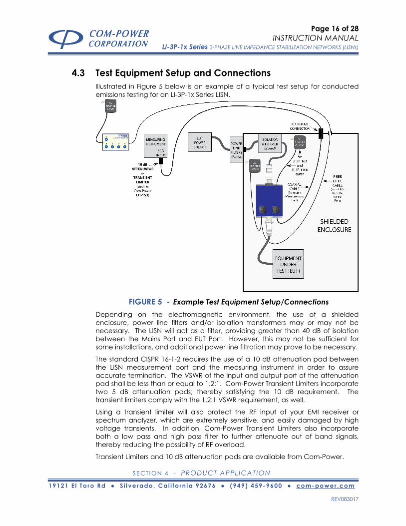
4.3 Test Equipment Setup and Connections Illustrated in Figure 5 below is an example of a typical test setup for conducted emissions testing for an LI-3P-1x Series LISN.
FIGURE 5 - Example Test Equipment Setup/Connections Depending on the electromagnetic environment, the use of a shielded enclosure, power line filters and/or isolation transformers may or may not be necessary. The LISN will act as a filter, providing greater than 40 dB of isolation between the Mains Port and EUT Port. However, this may not be sufficient for some installations, and additional power line filtration may prove to be necessary.
The standard CISPR 16-1-2 requires the use of a 10 dB attenuation pad between the LISN measurement port and the measuring instrument in order to assure accurate termination. The VSWR of the input and output port of the attenuation pad shall be less than or equal to 1.2:1. Com-Power Transient Limiters incorporate two 5 dB attenuation pads; thereby satisfying the 10 dB requirement. The transient limiters comply with the 1.2:1 VSWR requirement, as well.
Using a transient limiter will also protect the RF input of your EMI receiver or spectrum analyzer, which are extremely sensitive, and easily damaged by high voltage transients. In addition, Com-Power Transient Limiters also incorporate both a low pass and high pass filter to further attenuate out of band signals, thereby reducing the possibility of RF overload.
Transient Limiters and 10 dB attenuation pads are available from Com-Power.

Page 17 of 28
INSTRUCTION MANUAL LI-3P-1x Series 3-PHASE LINE IMPEDANCE STABILIZATION NETWORKS (LISNs)
SECTION 4 - PRODUCT APPLICATION
19121 E l To ro Rd ● S i l verado, Cal i fo rn ia 92676 ● (949) 459-9600 ● com-power .com
REV083017
4.3.1 LISN Input Power Connections Your LI-3P-1x Series LISN is provided with a five-conductor socket connector (with female contacts), which is used to connect the LISN to the EUT power source output cable. It mates with the Input Power Port Plug Connector affixed to the rear of the LISN. Illustrated in Figures 6 (16/32 Amp) and 7 (63/100) are the respective installation instructions for the connector.
FIGURE 6 - Wiring Instructions for Power Input Port Socket (16/32 Amp)
LIFT CONNECTORLIFT CONNECTORFROM HOUSINGFROM HOUSING
AND THREADAND THREADWIRING THROUGHWIRING THROUGH
STRAIN RELIEFSTRAIN RELIEFAND CONNECTORAND CONNECTOR
HOUSING.HOUSING.
ROTATE STRAINROTATE STRAINRELIEFRELIEF
COUNTER-COUNTER-CLOCKWISECLOCKWISETO LOOSENTO LOOSEN
INSERT THE ENDINSERT THE ENDOF A FLAT-BLADEOF A FLAT-BLADE
SCREWDRIVERSCREWDRIVEROR SIMILAR INTOOR SIMILAR INTOSLOT AS SHOWNSLOT AS SHOWN
ABOVE TO DEPRESSABOVE TO DEPRESSCLIP AND RELEASECLIP AND RELEASE
LOCKING MECHANISMLOCKING MECHANISM
ONCE LOCKINGONCE LOCKINGMECHANISM ISMECHANISM IS
RELEASED, ROTATERELEASED, ROTATECONNECTORCONNECTOR
APPROXIMATELYAPPROXIMATELYONE-EIGHTHONE-EIGHTH
TURN COUNTER-TURN COUNTER-CLOCKWISECLOCKWISE
LOOSEN THELOOSEN THESCREWS FOR THESCREWS FOR THERESPECTIVE WIRERESPECTIVE WIRE
TRAPS; INSERTTRAPS; INSERTSTRIPPED WIRESTRIPPED WIREENDS INTO THEENDS INTO THEAPPROPRIATE,APPROPRIATE,
RESPECTIVE WIRE RESPECTIVE WIRETRAPS ANDTRAPS AND
RE-TIGHTEN SCREWSRE-TIGHTEN SCREWS
RE-INSERTRE-INSERTCONNECTORCONNECTOR
INTOINTOCONNECTORCONNECTOR
HOUSINGHOUSING
ROTATEROTATECONNECTORCONNECTORONE-EIGHTHONE-EIGHTH
TURN CLOCKWISETURN CLOCKWISEUNTIL LOCKINGUNTIL LOCKING
MECHANISMMECHANISMRE-ENGAGES;RE-ENGAGES;RE-TIGHTENRE-TIGHTEN
STRAIN RELIEFSTRAIN RELIEFBY ROTATINGBY ROTATING
CLOCKWISE UNTILCLOCKWISE UNTILTIGHTENEDTIGHTENED
STEP #4STEP #4STEP #1STEP #1 STEP #2STEP #2 STEP #3STEP #3 STEP #5STEP #5 STEP #6STEP #6 STEP #7STEP #7

Page 18 of 28
INSTRUCTION MANUAL LI-3P-1x Series 3-PHASE LINE IMPEDANCE STABILIZATION NETWORKS (LISNs)
SECTION 4 - PRODUCT APPLICATION
19121 E l To ro Rd ● S i l verado, Cal i fo rn ia 92676 ● (949) 459-9600 ● com-power .com
REV083017
FIGURE 7 - Wiring Instructions for Power Input Port Socket (63/100 Amp)
LIFT CONNECTORLIFT CONNECTORFROM HOUSINGFROM HOUSING
AND THREADAND THREADWIRING THROUGHWIRING THROUGH
STRAIN RELIEFSTRAIN RELIEFAND CONNECTORAND CONNECTOR
HOUSING.HOUSING.
ROTATE STRAINROTATE STRAINRELIEFRELIEF
COUNTER-COUNTER-CLOCKWISECLOCKWISETO LOOSENTO LOOSEN
UNSCREW THEUNSCREW THEFOUR SCREWSFOUR SCREWSWHICH SECUREWHICH SECURE
THE CONNECTORTHE CONNECTORTO THETO THE
CONNECTORCONNECTORHOUSINGHOUSING
LOOSEN THELOOSEN THESCREWS FOR THESCREWS FOR THERESPECTIVE WIRERESPECTIVE WIRE
TRAPS; INSERTTRAPS; INSERTSTRIPPED WIRESTRIPPED WIREENDS INTO THEENDS INTO THEAPPROPRIATE,APPROPRIATE,
RESPECTIVE WIRE RESPECTIVE WIRETRAPS ANDTRAPS AND
RE-TIGHTEN SCREWSRE-TIGHTEN SCREWS
RE-INSERTRE-INSERTCONNECTORCONNECTOR
INTOINTOCONNECTORCONNECTOR
HOUSINGHOUSING
TIGHTEN THETIGHTEN THEFOUR SCREWSFOUR SCREWSWHICH SECUREWHICH SECURE
THE CONNECTORTHE CONNECTORTO THE CONNECTORTO THE CONNECTOR
HOUSING ANDHOUSING ANDRE-TIGHTEN STRAINRE-TIGHTEN STRAINRELIEF BY ROTATINGRELIEF BY ROTATINGCLOCKWISE UNTILCLOCKWISE UNTIL
TIGHTENEDTIGHTENED
STEP #3STEP #3STEP #1STEP #1 STEP #2STEP #2 STEP #4STEP #4 STEP #5STEP #5 STEP #6STEP #6

Page 19 of 28
INSTRUCTION MANUAL LI-3P-1x Series 3-PHASE LINE IMPEDANCE STABILIZATION NETWORKS (LISNs)
SECTION 4 - PRODUCT APPLICATION
19121 E l To ro Rd ● S i l verado, Cal i fo rn ia 92676 ● (949) 459-9600 ● com-power .com
REV083017
4.3.2 LISN Output Power Connections Your LI-3P-1x Series LISN is provided with a five-conductor plug connector (with male contacts), which is used to connect the LISN to the input power cable for the Equipment Under Test (EUT). It mates with the output power socket connector affixed to the front panel of the LISN. Illustrated in Figures 8 (16/32 Amp) and 9 (63/100 Amp) are the respective installation instructions for the connector.
FIGURE 8 - Wiring Instructions for EUT Power Port Plug (16/32 Amp)
LIFT CONNECTORLIFT CONNECTORFROM HOUSINGFROM HOUSING
AND THREADAND THREADWIRING THROUGHWIRING THROUGH
STRAIN RELIEFSTRAIN RELIEFAND CONNECTORAND CONNECTOR
HOUSING.HOUSING.
ROTATE STRAINROTATE STRAINRELIEFRELIEF
COUNTER-COUNTER-CLOCKWISECLOCKWISETO LOOSENTO LOOSEN
INSERT THE ENDINSERT THE ENDOF A FLAT-BLADEOF A FLAT-BLADE
SCREWDRIVERSCREWDRIVEROR SIMILAR INTOOR SIMILAR INTOSLOT AS SHOWNSLOT AS SHOWN
ABOVE TO DEPRESSABOVE TO DEPRESSCLIP AND RELEASECLIP AND RELEASE
LOCKING MECHANISMLOCKING MECHANISM
ONCE LOCKINGONCE LOCKINGMECHANISM ISMECHANISM IS
RELEASED, ROTATERELEASED, ROTATECONNECTORCONNECTOR
APPROXIMATELYAPPROXIMATELYONE-EIGHTHONE-EIGHTH
TURN COUNTER-TURN COUNTER-CLOCKWISECLOCKWISE
LOOSEN THELOOSEN THESCREWS FOR THESCREWS FOR THERESPECTIVE WIRERESPECTIVE WIRE
TRAPS; INSERTTRAPS; INSERTSTRIPPED WIRESTRIPPED WIREENDS INTO THEENDS INTO THEAPPROPRIATE,APPROPRIATE,
RESPECTIVE WIRE RESPECTIVE WIRETRAPS ANDTRAPS AND
RE-TIGHTEN SCREWSRE-TIGHTEN SCREWS
RE-INSERTRE-INSERTCONNECTORCONNECTOR
INTOINTOCONNECTORCONNECTOR
HOUSINGHOUSING
ROTATEROTATECONNECTORCONNECTORONE-EIGHTHONE-EIGHTH
TURN CLOCKWISETURN CLOCKWISEUNTIL LOCKINGUNTIL LOCKING
MECHANISMMECHANISMRE-ENGAGES;RE-ENGAGES;RE-TIGHTENRE-TIGHTEN
STRAIN RELIEFSTRAIN RELIEFBY ROTATINGBY ROTATING
CLOCKWISE UNTILCLOCKWISE UNTILTIGHTENEDTIGHTENED
STEP #4STEP #4STEP #1STEP #1 STEP #2STEP #2 STEP #3STEP #3 STEP #5STEP #5 STEP #6STEP #6 STEP #7STEP #7

Page 20 of 28
INSTRUCTION MANUAL LI-3P-1x Series 3-PHASE LINE IMPEDANCE STABILIZATION NETWORKS (LISNs)
SECTION 4 - PRODUCT APPLICATION
19121 E l To ro Rd ● S i l verado, Cal i fo rn ia 92676 ● (949) 459-9600 ● com-power .com
REV083017
FIGURE 9 - Wiring Instructions for EUT Power Port Plug (63/100 Amp)
LIFT CONNECTORLIFT CONNECTORFROM HOUSINGFROM HOUSING
AND THREADAND THREADWIRING THROUGHWIRING THROUGH
STRAIN RELIEFSTRAIN RELIEFAND CONNECTORAND CONNECTOR
HOUSING.HOUSING.
ROTATE STRAINROTATE STRAINRELIEFRELIEF
COUNTER-COUNTER-CLOCKWISECLOCKWISETO LOOSENTO LOOSEN
UNSCREW THEUNSCREW THEFOUR SCREWSFOUR SCREWSWHICH SECUREWHICH SECURE
THE CONNECTORTHE CONNECTORTO THETO THE
CONNECTORCONNECTORHOUSINGHOUSING
LOOSEN THELOOSEN THESCREWS FOR THESCREWS FOR THERESPECTIVE WIRERESPECTIVE WIRE
TRAPS; INSERTTRAPS; INSERTSTRIPPED WIRESTRIPPED WIREENDS INTO THEENDS INTO THEAPPROPRIATE,APPROPRIATE,
RESPECTIVE WIRE RESPECTIVE WIRETRAPS ANDTRAPS AND
RE-TIGHTEN SCREWSRE-TIGHTEN SCREWS
RE-INSERTRE-INSERTCONNECTORCONNECTOR
INTOINTOCONNECTORCONNECTOR
HOUSINGHOUSING
TIGHTEN THETIGHTEN THEFOUR SCREWSFOUR SCREWSWHICH SECUREWHICH SECURE
THE CONNECTORTHE CONNECTORTO THE CONNECTORTO THE CONNECTOR
HOUSING ANDHOUSING ANDRE-TIGHTEN STRAINRE-TIGHTEN STRAINRELIEF BY ROTATINGRELIEF BY ROTATINGCLOCKWISE UNTILCLOCKWISE UNTIL
TIGHTENEDTIGHTENED
STEP #3STEP #3STEP #1STEP #1 STEP #2STEP #2 STEP #4STEP #4 STEP #5STEP #5 STEP #6STEP #6

Page 21 of 28
INSTRUCTION MANUAL LI-3P-1x Series 3-PHASE LINE IMPEDANCE STABILIZATION NETWORKS (LISNs)
SECTION 5 - LISN OPERATION
19121 E l To ro Rd ● S i l verado, Cal i fo rn ia 92676 ● (949) 459-9600 ● com-power .com
REV083017
5.0 LISN Operation Operation of each of the LI-3P-1x Series LISN models includes local (front panel) and remote switching of the line under test. For the LI-3P-163 and LI-3P-1100 models, operation also includes operation of the two internal cooling fans.
5.1 Local (Front Panel) Operation When operated locally (from the front panel), the test lead selection switch on the LISN front panel is used to switch between L1, L2, L3 and N as the lead under
test. The switch also acts as the indicator of the line selected, as the LED line under test indicators will remain dark when the LISN is operated locally.
NOTE: Operation of the LISN from the front panel is possible when the REMOTE ACCESS LED is NOT lit, meaning there is no remote connection to the RLI-100 Remote LISN
Interface. When operating from the front panel, there is no need for the DC power input to the front panel or the fiber optic cable.
5.2 Remote Operation In order to enable remote operation, the 6 VDC AC power adapters must be plugged in and connected to the appropriate input power ports on the left side of the RLI-100 Remote LISN Interface and on the front panel of the LISN.
Then, connect one end of the fiber optic cable to the fiber optic port on the RLI-100, and connect the other end into the fiber optic port on the front panel of the LISN.
Once the fiber optic cable is connected, and both sides are powered, the link is established automatically. When linked, the REMOTE ACCESS and L1 LEDs on the LISN front panel should become lit, as well as the L1 LED on the RLI-100.
Once linked, you are now able to switch the test leads using the L1, L2, L3 and N buttons on the top surface of the RLI-100. The active (lit) line under test indicator LEDs on both the RLI-100 and the LISN front panel should immediately change with respect to which button is pressed.
TEST LEADSELECTION
L1
USB
L2 L3 N
RLI-100 REMOTE LISN INTERFACE
Page 22 of 28
INSTRUCTION MANUAL LI-3P-1x Series 3-PHASE LINE IMPEDANCE STABILIZATION NETWORKS (LISNs)
SECTION 5 - LISN OPERATION
19121 E l To ro Rd ● S i l verado, Cal i fo rn ia 92676 ● (949) 459-9600 ● com-power .com
REV083017
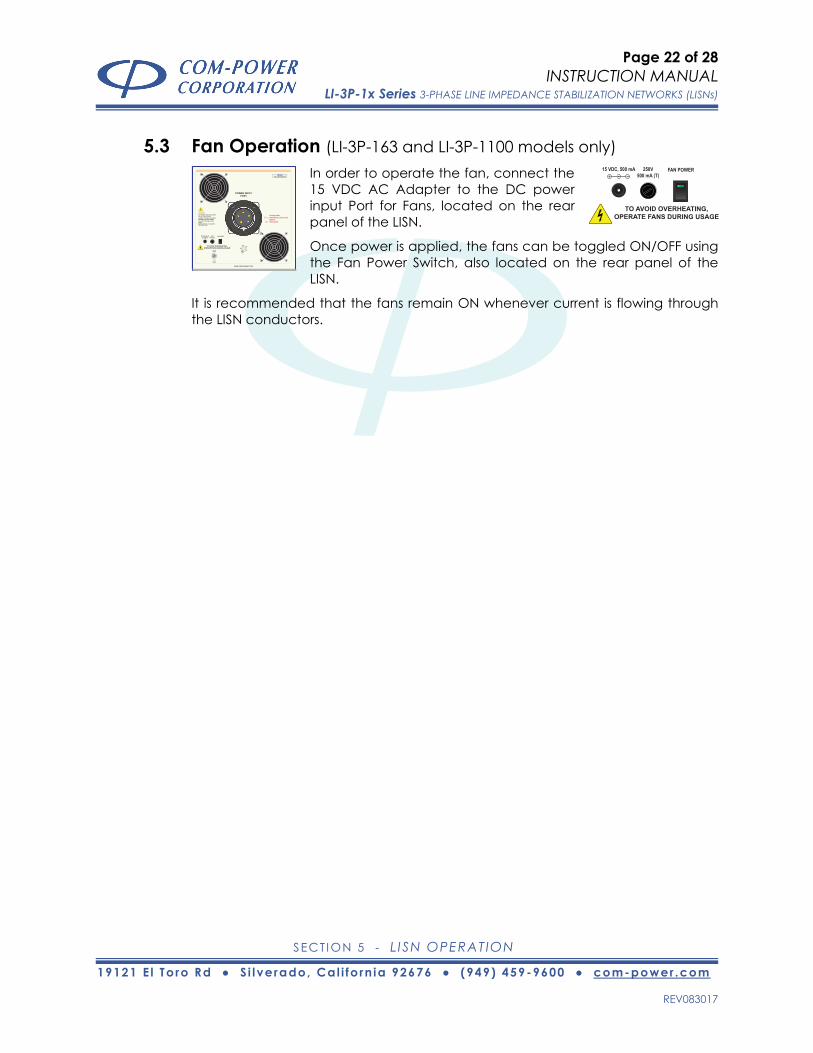
5.3 Fan Operation (LI-3P-163 and LI-3P-1100 models only) In order to operate the fan, connect the 15 VDC AC Adapter to the DC power input Port for Fans, located on the rear panel of the LISN.
Once power is applied, the fans can be toggled ON/OFF using the Fan Power Switch, also located on the rear panel of the LISN.
It is recommended that the fans remain ON whenever current is flowing through the LISN conductors.
CAUTION:TO PREVENT ELECTRIC SHOCK,DO NOT OPEN COVER.CONNECT PROTECTIVE EARTHBEFORE APPLYING POWER.NO USER SERVICEABLE PARTSINSIDE.REFER SERVICING TO QUALIFIEDPERSONNEL ONLY.
S/N: 2011xxxx
TO AVOID OVERHEATING,OPERATE FANS DURING USAGE
15 VDC, 500 mA 250V500 mA (T)
FAN POWER
www.com-power.com
xxx Amps Max.500 Volts AC (Line to Line)50/60 Hz705 Volts DC
3
POWER INPUTPORT
TO AVOID OVERHEATING,OPERATE FANS DURING USAGE
15 VDC, 500 mA 250V500 mA (T)
FAN POWER

Page 23 of 28
INSTRUCTION MANUAL LI-3P-1x Series 3-PHASE LINE IMPEDANCE STABILIZATION NETWORKS (LISNs)
SECTION 6 - LISN MEASUREMENTS
19121 E l To ro Rd ● S i l verado, Cal i fo rn ia 92676 ● (949) 459-9600 ● com-power .com
REV083017
6.0 LISN Measurements Measurements of conducted emissions, sometimes referred to as disturbance voltages, using any LI-3P-1x Series LISN are made individually on each current carrying conductor with reference to ground.
Measured values must be corrected in order to account for any losses incurred along the measurement path. These corrections usually include the insertion loss values for the LISN (with respect to the test lead being measured), coaxial measurement cables, attenuation pads or transient limiters, connecting adapters, etc.
6.1 LISN Insertion Loss Factors The Insertion Loss for an LISN is essentially, the difference, in dB, between the signal amplitude on the EUT power conductor at the entry point of the EUT Power Port into the LISN, and the amplitude of the same signal at the measurement port of the LISN.
All Com-Power LISNs are individually calibrated, and the insertion loss values are provided. There are eight (8) sets of Insertion Factors for each of the LI-3P-1x Series LISNs, so there are two (2) sets for each line; for REMOTE and LOCAL operation. This is necessary because the RF measurement paths for the two respective modes are considerably different, causing the insertion loss factors for the two modes to also be different.
Typical Insertion Loss values for the LI-3P-1x Series LISNs are listed in the Figure 10 table.
FIGURE 10 - Typical Insertion Loss Factors for LI-3P-1x Series LISNs
Equipment: Three-Phase Line Impedance Stabilization Network (LISN)Model: LI-3P-1x SeriesSerial Number: 2011xxxxCalibration Date: Typical Month / Typical Day / Typical Year
Local Remote Local Remote Local Remote Local Remote(MHz) (dB) (dB) (dB) (dB) (dB) (dB) (dB) (dB)
0.15 0.32 0.47 0.31 0.46 0.31 0.46 0.31 0.460.16 0.29 0.44 0.29 0.44 0.28 0.43 0.29 0.440.17 0.27 0.42 0.26 0.41 0.26 0.41 0.26 0.410.18 0.25 0.40 0.25 0.40 0.24 0.39 0.25 0.400.19 0.24 0.39 0.23 0.38 0.23 0.38 0.23 0.380.2 0.22 0.37 0.22 0.37 0.21 0.36 0.21 0.36
0.225 0.19 0.34 0.19 0.34 0.19 0.34 0.19 0.340.25 0.17 0.32 0.17 0.32 0.16 0.31 0.17 0.32
0.275 0.16 0.31 0.16 0.31 0.15 0.30 0.15 0.300.3 0.14 0.29 0.15 0.30 0.14 0.29 0.14 0.29
0.35 0.13 0.28 0.13 0.28 0.13 0.28 0.13 0.280.4 0.12 0.27 0.12 0.27 0.12 0.27 0.12 0.27
0.45 0.11 0.26 0.12 0.27 0.11 0.26 0.11 0.260.5 0.11 0.26 0.12 0.27 0.11 0.26 0.11 0.26
0.75 0.11 0.26 0.11 0.26 0.11 0.26 0.11 0.261 0.11 0.26 0.11 0.26 0.11 0.26 0.11 0.262 0.13 0.28 0.14 0.29 0.13 0.28 0.14 0.293 0.15 0.30 0.16 0.31 0.16 0.31 0.16 0.314 0.17 0.32 0.17 0.32 0.18 0.33 0.18 0.335 0.19 0.34 0.19 0.34 0.20 0.35 0.20 0.3510 0.28 0.43 0.28 0.43 0.30 0.45 0.30 0.4515 0.34 0.49 0.33 0.48 0.37 0.52 0.36 0.5120 0.34 0.49 0.35 0.50 0.38 0.53 0.37 0.5225 0.24 0.39 0.24 0.39 0.28 0.43 0.26 0.4130 0.08 0.23 0.10 0.25 0.11 0.26 0.08 0.23
Meter Reading + Insertion Loss Factor = Corrected Reading
Insertion Loss value to be added to receiver reading:
LISN INSERTION LOSS FACTORS ( Local & Remote Modes)
LINE 1 LINE 2 LINE 3 NEUTRALFrequency

Page 24 of 28
INSTRUCTION MANUAL LI-3P-1x Series 3-PHASE LINE IMPEDANCE STABILIZATION NETWORKS (LISNs)
SECTION 6 - LISN MEASUREMENTS
19121 E l To ro Rd ● S i l verado, Cal i fo rn ia 92676 ● (949) 459-9600 ● com-power .com
REV083017
6.1.1 Example Calculations An LI-3P-1x Series LISN was used to measure the conducted emissions of an EUT. The measurement port of the LISN was connected to the RF input of the measuring instrument via a coaxial cable, through a 10 dB attenuation pad. A signal is observed on LINE 2, with the LISN under remote control. The frequency of the signal is 20 MHz, and the measured amplitude is 40 dBuV. What is the actual amplitude of this signal on the LINE 2 conductor of the EUT input power?
For the system shown above, there are three (3) correction factors needed:
1) The LISN Insertion Loss Factor at 20 MHz for LINE 2 in remote mode 2) The insertion loss value of the 10 dB attenuator at 20 MHz 3) The insertion loss value of the coaxial cable at 20 MHz
We’ll assume that the insertion loss of the coaxial cable at 20 MHz is 2 dB, and the insertion loss of the 10 dB attenuator at 20 MHz is 10 dB. And, by referring to the typical insertion loss table shown in Figure 10, the LISN insertion loss factor for LINE 2 in remote mode is 0.5 dB (in practice, you will use your actual calibrated factors rather than the typical factors).
Measured amplitude @ 20 MHz = 40.0 dBuV LISN Insertion Loss Factor @ 20 MHz for LINE 2
in remote mode = 0.5 dB
Insertion Loss of 10 dB Attenuator @ 20 MHz = 10.0 dB Insertion Loss of Coaxial Cable @ 20 MHz = 2.0 dB
Measured Amplitude + Insertion Losses = Corrected Reading = 52.5 dBμV

Page 25 of 28
INSTRUCTION MANUAL LI-3P-1x Series 3-PHASE LINE IMPEDANCE STABILIZATION NETWORKS (LISNs)
SECTION 6 - LISN MEASUREMENTS
19121 E l To ro Rd ● S i l verado, Cal i fo rn ia 92676 ● (949) 459-9600 ● com-power .com
REV083017
6.1.2 LISN Insertion Loss Calibration The test setup for normalization and LISN Insertion Loss measurements are illustrated in Figure 11. The insertion loss factor is the difference (in dB) between the normalization measurements and the LISN insertion loss measurements.
FIGURE 11 - Setup Diagrams for LISN Insertion Loss Calibration
LISN Insertion Loss CalibrationNORMALIZATION SETUP
10 dB
INPUTRF
Network Analyzerwith S-Parameter Test Set
- or -Signal Generator
and Spectrum Analyzer/EMI Receiver
OUTPUTRF
10 dB
50Ω50Ω
50Ω50Ω
50Ω
LISN Insertion Loss CalibrationMEASUREMENT SETUP
10 dB
INPUTRF
Network Analyzerwith S-Parameter Test Set
- or -Signal Generator
and Spectrum Analyzer/EMI Receiver
OUTPUTRF
50Ω50Ω
50Ω50Ω
10 dB
50Ω

Page 26 of 28
INSTRUCTION MANUAL LI-3P-1x Series 3-PHASE LINE IMPEDANCE STABILIZATION NETWORKS (LISNs)
SECTION 6 - LISN MEASUREMENTS
19121 E l To ro Rd ● S i l verado, Cal i fo rn ia 92676 ● (949) 459-9600 ● com-power .com
REV083017
6.1.3 Non-LISN Insertion Loss Calibration Insertion Loss values for coaxial cables and most measurement system components having a single coaxial input and output, such as attenuators, filters, dc blocks, etc., can be easily determined through a simple calibration process.
The test setup for normalization and insertion loss measurements are illustrated in Figure 12. The insertion loss factor is the difference (in dB) between the normalization measurements and the insertion loss measurements.
FIGURE 12 - Setup Diagrams for Insertion Loss Calibration
Insertion Loss CalibrationNORMALIZATION MEASUREMENTS
Insertion Loss CalibrationINSERTION LOSS MEASUREMENTS
INPUTRF
Network Analyzerwith S-Parameter Test Set
- or -Synthesized RF Signal Generatorand Spectrum Analyzer/Receiver
OUTPUTRF
INPUTRF
Network Analyzerwith S-Parameter Test Set
- or -Synthesized RF Signal Generatorand Spectrum Analyzer/Receiver
OUTPUTRF
system componentto be calibrated
10 dB 10 dBX10 dB10 dB

Page 27 of 28
INSTRUCTION MANUAL LI-3P-1x Series 3-PHASE LINE IMPEDANCE STABILIZATION NETWORKS (LISNs)
SECTION 7 - WARRANTY
19121 E l To ro Rd ● S i l verado, Cal i fo rn ia 92676 ● (949) 459-9600 ● com-power .com
REV083017
7.0 Warranty Com-Power warrants to its Customers that the products it manufactures will be free from defects in materials and workmanship for a period of three (3) years. This warranty shall not apply to:
• Transport damages during shipment from your plant. • Damages due to poor packaging. • Products operated outside their specifications. • Products Improperly maintained or modified. • Consumable items such as fuses, power cords, cables, etc. • Normal wear • Calibration • Products shipped outside the United States without the prior knowlege of
Com-Power.
In addition, Com-Power shall not be obliged to provide service under this warranty to repair damage resulting from attempts to install, repair, service or modify the instrument by personnel other than Com-Power service representatives.
Under no circumstances does Com-Power recognize or assume liability for any loss, damage or expense arising, either directly or indirectly, from the use or handling of this product, or any inability to use this product separately or in combination with any other equipment.
When requesting warranty services, it is recommended that the original packaging material be used for shipping. Damage due to improper packaging will void warranty.
If you feel that the product is not working as intended, or is malfunctioning, please contact Com-Power for assistance. In the case of repair or complaint, Please visit our website at www.com-power.com and fill out an RMA form (http://com-power.com/repairservicereq.asp). The RMA number should be displayed in a prominent location on the packaging and on the product, along with a description of the problem, and your contact information.

Page 28 of 28
INSTRUCTION MANUAL LI-3P-1x Series 3-PHASE LINE IMPEDANCE STABILIZATION NETWORKS (LISNs)
SECTION 8 - PRODUCT MAINTENANCE
19121 E l To ro Rd ● S i l verado, Cal i fo rn ia 92676 ● (949) 459-9600 ● com-power .com
REV083017
8.0 Product Maintenance This product contains no user serviceable parts. If the unit does not operate or needs calibration, please contact Com-Power Corporation. Any modifications or repairs performed on the unit by someone other than an authorized factory trained technician will void warranty.
The exterior surface may be cleaned with mild detergent and then be wiped with a dry, clean, lint-free cloth. Use care to avoid liquids or other foreign objects entering the chassis.