instruction manual - hitachi-da.com · mechanism not supplied by hitachi, ltd., and process line...
TRANSCRIPT

Hitachi Europe GmbH
Instruction ManualHITACHI Inverter
L300P Series - ... HFEThree phase input 200/400V class
NB601EX

i
SAFETY
For the Best Results with L300P Series inverter, read this manual and all of the warning sign attachedto the inverter carefully before installing and operating it, and follow the instructions exactly. Keep this
manual handy for your quick reference.
Definitions and Symbols
A safety instruction (message) is given with a hazard alert symbol and a signal word;
WARNING or CAUTION. Each signal word has the following meaning throughout this manual.
This symbol means hazardous high voltage. It used to call your attention toitems or operations that could be dangerous to you or other personsoperating this equipment.Read these message and follow these instructions carefully.
This is the "Safety Alert Symbol" This symbol is used to call your attention toitems or operations that could be dangerous to you or other persons operatingthis equipment.Read these messages and follow these instructions carefully.
WARNING WARNINGIndicates a potentially hazardous situation which, if not avoided, can result inserious injury or death.
CAUTION CAUTION
Indicates a potentially hazardous situation which, if not avoided, can result inminor to moderate injury, or serious damage of product.The matters described under may, if not avoided, lead to seriousresults depending on the situation. Important matters are describedin CAUTION ( as well as WARNING ), so be sure to observe them.
NOTE NOTENotes indicate an area or subject of special merit, emphasizing either theproduct's capabilities or common errors in operation or maintenance.
HAZARDOUS HIGH VOLTAGE
Motor control equipment and electronic controllers are connected to hazardous line voltages. When
servicing drives and electronic controllers, there might be exposed components with cases or protru-
sions at or above line potential. Extreme care should be taken to product against shock.
Stand on an insulating pad and make it a habit to use only one hand when checking components.
Always work with another person in case an emergency occurs. Disconnect power before checking
controllers or performing maintenance. Be sure equipment is properly grounded. Wear safety glasses
whenever working on an electronic controllers or rotating electrical equipment.
CAUTION
ii
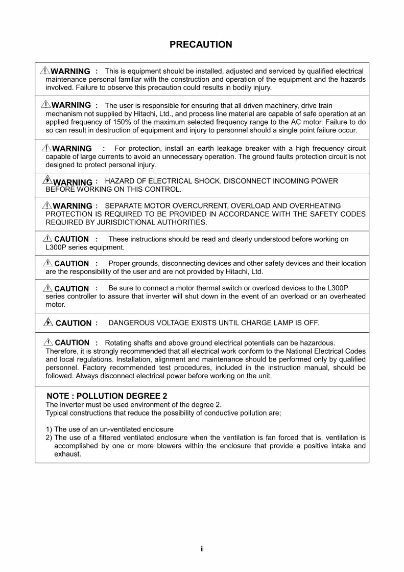
PRECAUTION
: This is equipment should be installed, adjusted and serviced by qualified electricalmaintenance personal familiar with the construction and operation of the equipment and the hazardsinvolved. Failure to observe this precaution could results in bodily injury.
: The user is responsible for ensuring that all driven machinery, drive trainmechanism not supplied by Hitachi, Ltd., and process line material are capable of safe operation at anapplied frequency of 150% of the maximum selected frequency range to the AC motor. Failure to doso can result in destruction of equipment and injury to personnel should a single point failure occur.
: For protection, install an earth leakage breaker with a high frequency circuitcapable of large currents to avoid an unnecessary operation. The ground faults protection circuit is notdesigned to protect personal injury.
: HAZARD OF ELECTRICAL SHOCK. DISCONNECT INCOMING POWERBEFORE WORKING ON THIS CONTROL.
: SEPARATE MOTOR OVERCURRENT, OVERLOAD AND OVERHEATINGPROTECTION IS REQUIRED TO BE PROVIDED IN ACCORDANCE WITH THE SAFETY CODESREQUIRED BY JURISDICTIONAL AUTHORITIES.
: These instructions should be read and clearly understood before working onL300P series equipment.
: Proper grounds, disconnecting devices and other safety devices and their locationare the responsibility of the user and are not provided by Hitachi, Ltd.
: Be sure to connect a motor thermal switch or overload devices to the L300Pseries controller to assure that inverter will shut down in the event of an overload or an overheatedmotor.
: DANGEROUS VOLTAGE EXISTS UNTIL CHARGE LAMP IS OFF.
: Rotating shafts and above ground electrical potentials can be hazardous.Therefore, it is strongly recommended that all electrical work conform to the National Electrical Codesand local regulations. Installation, alignment and maintenance should be performed only by qualifiedpersonnel. Factory recommended test procedures, included in the instruction manual, should befollowed. Always disconnect electrical power before working on the unit.
NOTE : POLLUTION DEGREE 2The inverter must be used environment of the degree 2.Typical constructions that reduce the possibility of conductive pollution are;
1) The use of an un-ventilated enclosure2) The use of a filtered ventilated enclosure when the ventilation is fan forced that is, ventilation is
accomplished by one or more blowers within the enclosure that provide a positive intake andexhaust.
WARNING
WARNING
WARNING
WARNING
CAUTION
CAUTION
CAUTION
CAUTION
CAUTION
WARNING
iii
Cautions for EMC (Electromagnetic Compatibility)You are required to safety the EMC directive (89/336/EEC) when using the L300P inverter in aEuropean country. To safety the EMC directive and to comply with standard, follows the checklistbelow.
: This equipment should be installed, adjusted, and serviced by qualifiedpersonal familiar with construction and operation of the equipment and the hazardsinvolved. Failure to observe this precaution could result in bodily injury.
1. The power supply to L300P inverter must meet these specifications:a. Voltage fluctuation +/-10% or less.b. Voltage imbalance +/-3% or less.c. Frequency variation +/-4% or less.d. Voltage distortion THD = 10% or less.
2. Installation measure:a. Use a filter designed for L300P inverter.
3. Wiringa. Shielded wire (screened cable) is required for motor wiring, and the length must be less than 20
meters.b. The carrier frequency setting must be less than 3 kHz to satisfy EMC requirements.c. Separate the main circuit from the signal/process circuit wiring.d. In case of remote operating with connector cable, the inverter does not conform to EMC.
4. Environmental conditions – when using a filter, follow these guidelines:a. Ambient air temperature: -10 - +40 ºC.b. Humidity: 20 to 90% RH (non-condensing)c. Vibration: 5.9 m/sec2 (0.6 G) 10 – 55Hz. (L300P-110-300LF/110-300HF)
2.94 m/sec2 (0.3 G) 10 – 55Hz. (L300P-370-750LF/370-1320HF)d. Location: 1000meters or less altitude, indoors (no corrosive gas or dust)
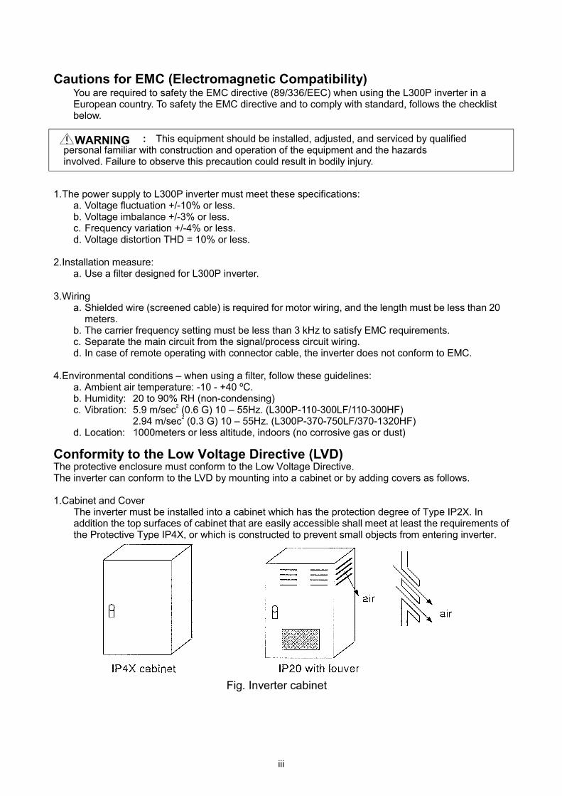
Conformity to the Low Voltage Directive (LVD)The protective enclosure must conform to the Low Voltage Directive.The inverter can conform to the LVD by mounting into a cabinet or by adding covers as follows.
1.Cabinet and CoverThe inverter must be installed into a cabinet which has the protection degree of Type IP2X. Inaddition the top surfaces of cabinet that are easily accessible shall meet at least the requirements ofthe Protective Type IP4X, or which is constructed to prevent small objects from entering inverter.
Fig. Inverter cabinet
WARNING
iv
UL Warnings and Cautions Manual for L300P series
This auxiliary instruction manual should be delivered to the end user.
1.Wiring Warnings for Electrical Practices and Wire Specifications
(1) ! WARNING : "Use 60/75 ºC CU wire only" or equivalent.
(2) ! WARNING : "Open Type Equipment."
For models with L300P 900-1320H.
(3) ! WARNING : "Suitable for use on a circuit capable or delivering not more than 10,000 rms
symmetrical amperes, 240 V maximum." For models with suffix L.
(4) ! WARNING : "Suitable for use on a circuit capable or delivering not more than 10,000 rms
symmetrical amperes, 480 V maximum." For models with suffix H.
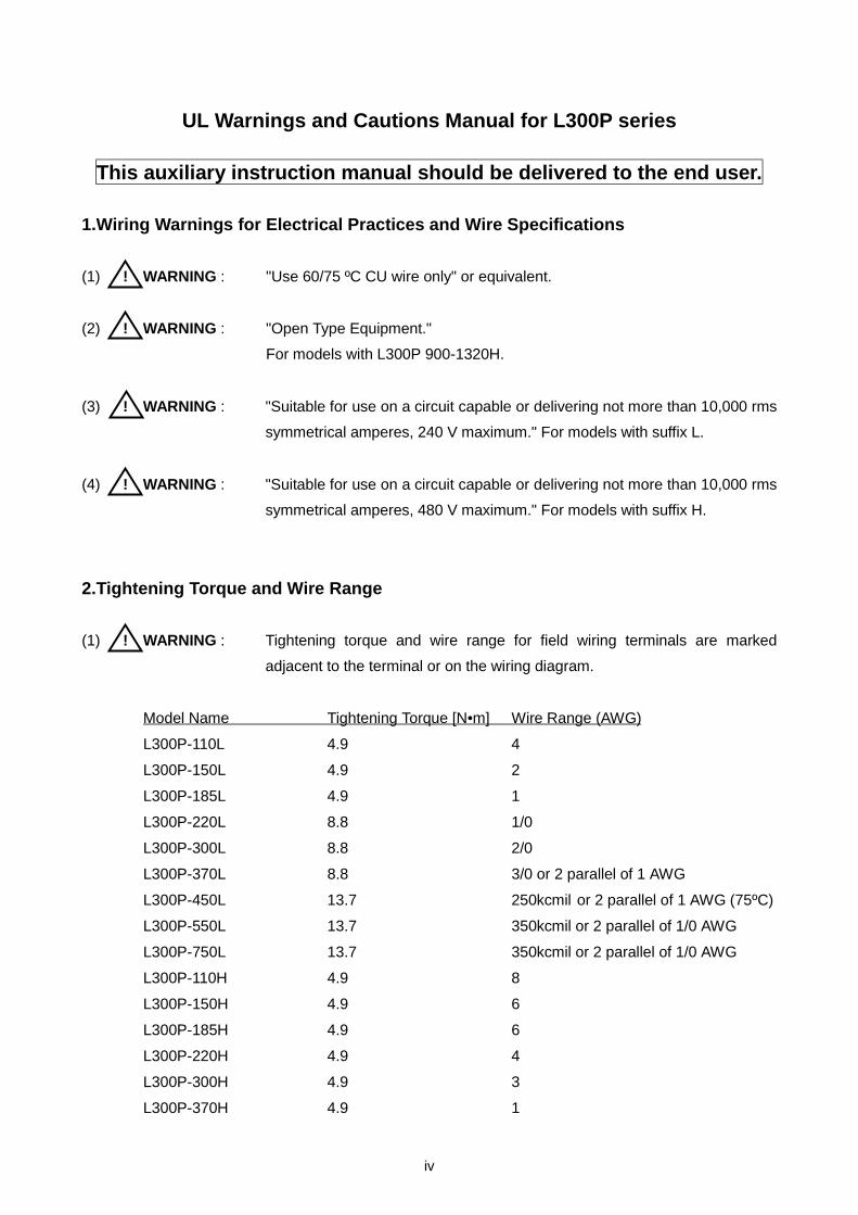
2.Tightening Torque and Wire Range
(1) ! WARNING : Tightening torque and wire range for field wiring terminals are marked
adjacent to the terminal or on the wiring diagram.
Model Name Tightening Torque [N•m] Wire Range (AWG)
L300P-110L 4.9 4
L300P-150L 4.9 2
L300P-185L 4.9 1
L300P-220L 8.8 1/0
L300P-300L 8.8 2/0
L300P-370L 8.8 3/0 or 2 parallel of 1 AWG
L300P-450L 13.7 250kcmil or 2 parallel of 1 AWG (75ºC)
L300P-550L 13.7 350kcmil or 2 parallel of 1/0 AWG
L300P-750L 13.7 350kcmil or 2 parallel of 1/0 AWG
L300P-110H 4.9 8
L300P-150H 4.9 6
L300P-185H 4.9 6
L300P-220H 4.9 4
L300P-300H 4.9 3
L300P-370H 4.9 1

v
L300P-450H 8.8 1
L300P-550H 8.8 1/0
L300P-750H 8.8 250kcmil or 2 parallel of 1 AWG (75ºC)
L300P-900H 13.7 250kcmil or 2 parallel of 1 AWG (75ºC)
L300P-1100H 13.7 350kcmil or 2 parallel of 1/0 AWG
L300P-1320H 13.7 350kcmil or 2 parallel of 1/0 AWG
3.Circuit Breaker / Fuse Size
(1) ! WARNING : Distribution fuse/circuit breaker size marking is included in the manual to
indicate that the unit shall be connected with an UL Listed inverse time circuit
breaker, rated 600 V with the current ratings or an UL Listed fuse as shown
in the table below.
Model Name Tightening Torque [N•m] Wire Range (AWG)
L300P-110L 60 60
L300P-150L 70 70
L300P-185L 90 90
L300P-220L 100 100
L300P-300L 150 150
L300P-370L 175 175
L300P-450L 200 200
L300P-550L 250 250
L300P-750L 300 300
L300P-110H 30 30
L300P-150H 35 35
L300P-185H 50 50
L300P-220H 50 50
L300P-300H 70 70
L300P-370H 80 80
L300P-450H 100 100
L300P-550H 125 125
L300P-750H 150 150
L300P-900H - 200
L300P-1100H - 225
L300P-1320H - 300

vi
4.Others
(1) ! WARNING : "Field wiring connection must be made by an UL Listed and CSA Certified
closed-loop terminal connector sized for the wire gauge involved. Connector
must be fixed using the crimp tool specified by the connector manufacturer.",
or equivalent wording included in the manual.

vii
Revision History Table
No. Revision ContentsThe Dateof Issue
OperationManual No.
1 Initial Release of Manual NB601AX Sep. 1999 NB601AX
2 The data 02 of the command b004 was added The carrier frequency of the capacity 37kW and more was added.
Oct. 1999 NB601BX
3 The specification of the capacity 75kW and more was added. Jun. 2000 NB601CX
4 A skipped number. NB601DX
5 The specification of the capacity 90-132kW and more was added Feb. 2001 NB601EX

viii
SAFETY PRECAUTIONS
1.Installation
• Be sure to install the unit on flame resistant material such as metal.Otherwise, there is a danger of fire. …… p.2-2
• Be sure not to place anything inflammable in the vicinity.Otherwise, there is a danger of fire. …… p.2-2
• Do not carry unit by top cover, always carry by supporting base of unit.There is a risk of falling and injury. …… p.2-2
• Be sure not to let the foreign matter enter such as cut wire refuse, spatterfrom welding, iron refuse, wire, dust, etc.
Otherwise, there is a danger of fire.…… p.2-5
• Be sure to install it in a place which can bear the weight according to thespecifications in the text. (Chapter 6. Specifications)
Otherwise, it may fall and there is a danger of injury.…… p.2-1
• Be sure to install the unit on a perpendicular wall which is not subject tovibration.
Otherwise, it may fall and there is a danger of injury.…… p.2-3
• Be sure not to install and operate an inverter which is damaged or parts ofwhich are missing.
Otherwise, there is a danger of injury.…… p.2-2
• Be sure to install it in a room which is not exposed to direct sunlight and iswell ventilated. Avoid environments which tend to be high in temperature,high in humidity or to have dew condensation, as well as places with dust,corrosive gas, explosive gas, inflammable gas, grinding-fluid mist, saltdamage, etc.
Otherwise, there is a danger of fire.
…… p.2-2
CAUTION

ix
SAFETY PRECAUTIONS
2.Wiring
• Be sure to ground the unit.Otherwise, there is a danger of electric shock and/or fire. …… p.2-9
• Wiring work shall be carried out by electrical experts.Otherwise, there is a danger of electric shock and/or fire. …… p.2-6
• Implement wiring after checking that the power supply is off.It might incur electric shock and/or fire. …… p.2-8
• After installing the main body, carry out wiring.Otherwise, there is a danger of electric shock and/or injury. …… p.2-5
• Do not remove the rubber bush. (11 to 75kW)Due to the possibility that a wire may be damaged, shorted or may havea ground fault with the edge of the wiring cover.
…… p.2-4
• Make sure that the input voltage is:Three phase 200 to 240V 50/60Hz (for models with suffix L)Three phase 380 to 480V 50/60Hz (for models with suffix H)
…… p.2-6
• Be sure not to input a single phase.Otherwise, there is a danger of fire. …… p.2-8
• Be sure not to connect AC power supply to the output terminals(U, V, W).Otherwise, there is a danger of injury and/or fire. …… p.2-5
• Be sure not to connect the resistor to DC terminals (PD,P and N) directly.Otherwise, there is a danger of fire. …… p.2-5
• Be sure to set the earth leakage breaker or the fuse(s) (the same phase asthe main power supply) in the operation circuit.
Otherwise, there is a danger of fire.…… p.2-12
• As for motor leads, earth leakage breakers and electromagnetic contactors,be sure to use the equivalent ones with the specified capacity (rated).
Otherwise, there is a danger of fire.…… p.2-12
• Do not stop operation by switching off the electromagnetic contactors on theprimary or secondary sides of the inverter.
Otherwise, there is a danger of injury and/or machine breakage.…… p.2-6
• Fasten the screws with the specified fastening torque. Check so that thereis no loosening of screws.
Otherwise, there is a danger of fire.…… p.2-12
WARNING
CAUTION

x
SAFETY PRECAUTIONS
3.Control and operation
• While the inverter is energized, be sure not to touch the main terminal or tocheck the signal or put on/off wire and/or connector.
Otherwise, there is a danger of electric shock.…… p.3-1
• Be sure to turn on the input power supply after closing the front case.While being energized, be sure not to open the front case.
Otherwise, there is a danger of electric shock.…… p.3-1
• Be sure not to operate the switches with wet hands.Otherwise, there is a danger of electric shock. …… p.3-1
• While the inverter is energized, be sure not to touch the inverter terminalseven during stoppage.
Otherwise, there is a danger of electric shock.…… p.3-1
• If the retry mode is selected, it may suddenly restart during the trip stop. Besure not to approach the machine. (Be sure to design the machine so thatpersonnel safety will be secured even if it restarts.)
Otherwise, there is a danger of injury.
…… p.3-1
• Be sure not to select retry mode for up and down equipment or travelingequipment, because there is output free-running mode in term of retry.
Otherwise, there is a danger of injury and/or machine breakage.…… p.3-1
• Even if the power supply is cut for a short period of time, it may restartoperation after the power supply is recovered if the operation command isgiven. If it may incur danger to personnel, be sure to make a circuit so that itwill not restart after power recovery.
Otherwise, there is a danger of injury.
…… p.3-1
• The Stop Key is effective only when the function is set. Be sure to preparethe Key separately from the emergency stop.
Otherwise, there is a danger of injury.…… p.3-1
• After the operation command is given, if the alarm reset is conducted, it willrestart suddenly. Be sure to set the alarm reset after checking the operationcommand is off.
Otherwise, there is a danger of injury.
…… p.3-1
• Be sure not to touch the inside of the energized inverter or to put a bar intoit.
Otherwise, there is a danger of electric shock and/or fire.…… p.3-1
WARNING
xi
SAFETY PRECAUTIONS
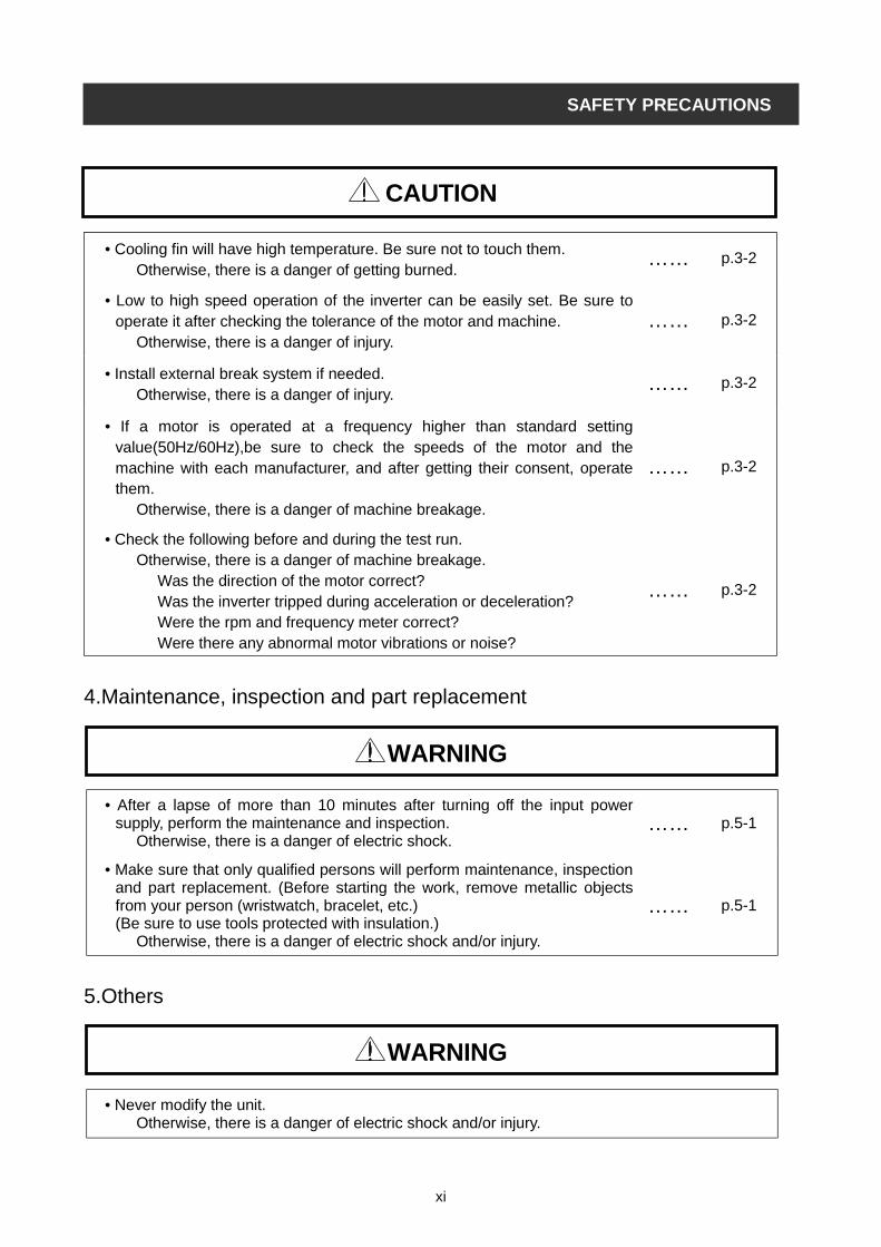
• Cooling fin will have high temperature. Be sure not to touch them.Otherwise, there is a danger of getting burned.
…… p.3-2
• Low to high speed operation of the inverter can be easily set. Be sure tooperate it after checking the tolerance of the motor and machine.
Otherwise, there is a danger of injury.…… p.3-2
• Install external break system if needed.Otherwise, there is a danger of injury.
…… p.3-2
• If a motor is operated at a frequency higher than standard settingvalue(50Hz/60Hz),be sure to check the speeds of the motor and themachine with each manufacturer, and after getting their consent, operatethem.
Otherwise, there is a danger of machine breakage.
…… p.3-2
• Check the following before and during the test run.Otherwise, there is a danger of machine breakage.
Was the direction of the motor correct?Was the inverter tripped during acceleration or deceleration?Were the rpm and frequency meter correct?Were there any abnormal motor vibrations or noise?
…… p.3-2
4.Maintenance, inspection and part replacement
• After a lapse of more than 10 minutes after turning off the input powersupply, perform the maintenance and inspection.
Otherwise, there is a danger of electric shock.…… p.5-1
• Make sure that only qualified persons will perform maintenance, inspectionand part replacement. (Before starting the work, remove metallic objectsfrom your person (wristwatch, bracelet, etc.)(Be sure to use tools protected with insulation.)
Otherwise, there is a danger of electric shock and/or injury.
…… p.5-1
5.Others
• Never modify the unit.Otherwise, there is a danger of electric shock and/or injury.
CAUTION
WARNING
WARNING
xii
Table of Contents
TABLE OF CONTENTS
Chapter 1 General Descriptions1.1 Inspection upon Unpacking……………………………………………… 1-1
1.1.1 Inspection of the unit………………………………………………………………… 1-1
1.1.2 Instruction manual…………………………………………………………………… 1-1
1.2 Question and Warranty of the Unit……………………………………… 1-2
1.2.1 Request upon asking………………………………………………………………… 1-2
1.2.2 Warranty for the unit………………………………………………………………… 1-2
1.3 Appearance……….……………………………………………………… 1-3
1.3.1 Appearance and Names of Parts…………………………………………………… 1-3
Chapter 2 Installation and Wiring2.1 Installation………………………………………………………………….. 2-1
2.1.1 Installation………………………………………………………………………………. 2-2
2.1.2 Blind cover of wiring parts ……………………………………………………………. 2-4
2.2 Wiring……………………………………………………………………….. 2-5
2.2.1 Terminal Connection Diagram………………………………………………………… 2-6
2.2.2 Main circuit wiring……………………………………………………………………… 2-8
2.2.3 Terminal Connection Diagram………………………………………………………… 2-13
2.2.4 Digital operator wiring………………………………………………………………… 2-15
Chapter 3 Operation3.1 Operation……………………………………………………………………. 3-3
3.2 Test Run……………………………………………………………………… 3-4
Chapter 4 Explanation of Function4.1 About Digital Operator (OPE-SR)…………………………………………. 4-1
4.2 Code list………………………………………………………………………. 4-5
4.3 Explanation of function……………………………………………………… 4-10
4.3.1 Monitor mode
Output frequency monitor, Output current monitor, Operation direction monitor
PID feedback monitor …………………………… 4-10
Intelligent input monitor, Intelligent output monitor …………………………... 4-11
Frequency conversion monitor, Output voltage monitor, Input electric power monitor….4-12
Accumulated time monitor on Run, Power ON time monitor, Trip time monitor, Trip monitor……..4-13

xiii
Table of Contents
4.3.2 Function mode
Setting of the output frequency, Operation direction, Selection with limits of operation direction,
Frequency command selection …………………………… 4-14
Operation command selection, Selection on stop, Selection of the stop key ……..
Adjustable time ……………………………
Base frequency ……………………………
Maximum frequency, Carrier frequency …………………………….
External analog input ……………………………
Input frequency Start/End ……………………………
Setting analog input filter, Output voltage gain ……………………………
Control system (V/f Characteristic) ……………………………
Torque boost ……………………………
Direct current braking (DB) ……………………………
Frequency limiter ……………………………
Frequency jump function, Acceleration stop function ………………………….
PID function ……………………………
Automatic energy-saving operation function ……………………………
Two-stage acceleration and deceleration function (2CH) ………………………
Acceleration and deceleration pattern …………………………..
Instantaneous power failure / under-voltage ……………………………
Open phase protection function selection, Electronic thermal function …………
Overload restriction / Overload advance notice ………………………….
Start frequency, Reduced voltage start selection …………………………..
BRD (dynamic braking) function, Cooling fan operating selection ……………….
Intelligent input terminal setting, Input terminal a/b (NO/NC) selection …………
Multi-speed operation function ……………………………
Jogging operation (JG) ……………………………
Second control function (SET), Software lock mode selection (SFT) .……………
Free-run stop (FRS) ……………………………
Commercial power source switching (CS) …………………………….
Reset (RS) ……………………………
Unattended start protection (USP), UP / DOWN selection (UP/DWN)……………
External trip (EXT), 3 Wire input function (STA, STP, F/R) ……………………
Intelligent output terminal setting ……………………………
Intelligent output terminal a/b (NO/NC) selection ……………………………
Signal during run (RUN), Frequency arrival signal (FA1, FA2, FA3) ……………
RUN time/power ON time over (RNT/ONT), Force operation ope function ……
FM terminal ……………………………
4-15
4-16
4-17
4-18
4-19
4-20
4-21
4-22
4-24
4-25
4-28
4-29
4-30
4-31
4-32
4-33
4-34
4-36
4-38
4-40
4-41
4-42
4-43
4-44
4-45
4-46
4-47
4-48
4-49
4-50
4-51
4-52
4-53
4-55
4-56

xiv
Table of Contents
AM terminal, AMI terminal, External thermistor (TH) …………………………
Initialization setting ……………………………
Display selection ……………………………
Stabilized factor, Operation selection on option error, Motor constant …………
Communication function …………………………….
4.4 Protection function list……………………………………………………….
4.4.1 Protection function………………………………………………………………………..
4.4.2 Trip monitor display……………………………………………………………………….
4.4.3 Warning Monitor display………………………………………………………………….
Chapter 5 Maintenance, Inspection5.1 Precaution for Maintenance/Inspection……………………………………
5.1.1 Daily inspection……………………………………………………………………………
5.1.2 Cleaning……………………………………………………………………………………
5.1.3 Regular inspection………………………………………………………………………..
5.2 Daily inspection and regular inspection …………………………………..
5.3 Megger test…………………………………………………………………..
5.4 Withstand Voltage test………………………………………………………
5.5 The method to check Inverter, converter part…………………………….
5.6 Capacitor Life Curve…………………………………………………………
Chapter 6 Specification6.1 Standard specification list…………………………………………………..
6.2 Dimension……………………………………………………………………..
4-57
4-58
4-59
4-60
4-61
4-75
4-75
4-78
4-79
5-1
5-1
5-1
5-1
5-2
5-3
5-3
5-4
5-5
6-1
6-2

1
1
H
1
f
u
Chapter 1 General Descriptions
1-1
.1 Inspection upon Unpacking
.1.1 Inspection of the unit
Open the package and pick out the inverter, please check the following item.
If you discover any unknown parts or the unit is in bad condition, please contact your supplier or the local
itachi Distributor.
(1) Make sure that there was no damage (injury, falling or dents in the body) during transportation of the
unit.
(2) After unpacking the unit, make sure that the package contains one operation manual for the Inverter.
(3) Make sure that the product is the one you ordered by checking the specification label.
.1.2 Instruction manualThis instruction manual is the manual for the HITACHI Inverter L300P Series.
Before operation of the Inverter, read the manual carefully. After Reading this manual, keep it to hand for
uture reference.
When using optional units for this inverter; please refer to the instruction manuals packed with the optional
nits.
This instruction manual should be delivered to the end user.
Picture 1-1 Position of specification label
Specifications label
Picture 1-2 Contents of specifications label
Output ratings
Maximum applicable motorInverter model
Input ratings
Production number
1-2
1.2 Question and Warranty of the Unit
1.2.1 Request upon askingIf you have any questions regarding damage to the unit, unknown parts or for general inquiries please contact
your supplier or the local Hitachi Distributor with the following information.
(1) Inverter Model
(2) Production Number (MFG No.)
(3) Date of Purchase
(4) Reason for Calling
Damaged part and its condition etc.
Unknown parts and their contents etc.
1.2.2 Warranty for the unit The warranty period of the unit is one year after the purchase date.
However within the warranty period, the warranty will be void if the fault is due to;
(1) Incorrect use as directed in this manual, or attempted repair by unauthorized personnel
(2) Any damage sustained, other than from transportation (Which should be reported immediately)
(3) Using the unit beyond the limits of the specification.
(4) Natural Disasters: Earthquakes, Lightning, etc
The warranty is for the inverter only, any damage caused to other equipment by malfunction of the inverter
is not covered by the warranty.
Any examination or repair after the warranty period (one year) is not covered. And within the warranty period
any repair and examination which results in information showing the fault was caused by any of the items
mentioned above,. the repair and examination cost are not covered.
If you have any questions regarding the warranty please contact either your supplier or the local Hitachi
Distributor.
Please refer to the back cover for a list of the local Hitachi Distributors.
Chapter 1 General Descriptions

1-3
1.3 Appearance
1.3.1 Appearance and Names of Parts
Chapter 1 General Descriptions
Appearance from the front
Connector
Installation point
of self-contained option
Control circuit terminals
Main circuit terminals
Wiring blind cover
Front cover removed
Power lamp
Alarm lamp
Digital operator
Spacer cover
Terminals cover
Specifications
Label
Front cover
(Note)When you use cable for remote operation, please remove connector.

2-1
2.1 Installation
• Be sure to install the unit on flame resistant material such as metal.Otherwise, there is a danger of fire.
• Be sure not to place anything inflammable in the vicinity.Otherwise, there is a danger of fire.
• Do not carry unit by top cover, always carry by supporting base of unit.There is a risk of falling and injury.
• Be sure not to let the foreign matter enter such as cut wire refuse, spatter from welding, iron refuse, wire,dust, etc.
Otherwise, there is a danger of fire.
• Be sure to install it in a place which can bear the weight according to the specifications in the text. (Chapter 6. Specifications)
Otherwise, it may fall and there is a danger of injury.
• Be sure to install the unit on a perpendicular wall which is not subject to vibration.Otherwise, it may fall and there is a danger of injury.
• Be sure not to install and operate an inverter which is damaged or parts of which are missing.Otherwise, there is a danger of injury.
• Be sure to install it in a room which is not exposed to direct sunlight and is well ventilated. Avoidenvironments which tend to be high in temperature, high in humidity or to have dew condensation, aswell as places with dust, corrosive gas, explosive gas, inflammable gas, grinding-fluid mist, salt damage,etc.
Otherwise, there is a danger of fire.
Chapter 2 Installation and Wiring
CAUTION
2-2
2.1.1 Installation1. Transportation
This inverter has plastic parts. So handle with care.
Do not over tighten the wall mounting fixings as the mountings may crack, causing is a risk of falling.
Do not install or operate the inverter if there appears to be damage or parts missing.
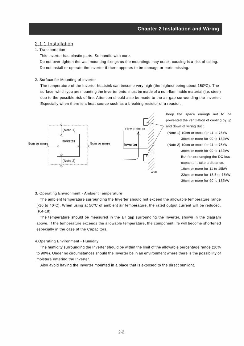
2. Surface for Mounting of Inverter
The temperature of the Inverter heatsink can become very high (the highest being about 150ºC). The
surface, which you are mounting the Inverter onto, must be made of a non-flammable material (i.e. steel)
due to the possible risk of fire. Attention should also be made to the air gap surrounding the Inverter.
Especially when there is a heat source such as a breaking resistor or a reactor.
3. Operating Environment - Ambient Temperature
The ambient temperature surrounding the Inverter should not exceed the allowable temperature range
(-10 to 40ºC). When using at 50ºC of ambient air temperature, the rated output current will be reduced.
(P.4-18)
The temperature should be measured in the air gap surrounding the Inverter, shown in the diagram
above. If the temperature exceeds the allowable temperature, the component life will become shortened
especially in the case of the Capacitors.
4.Operating Environment - Humidity
The humidity surrounding the Inverter should be within the limit of the allowable percentage range (20%
to 90%). Under no circumstances should the Inverter be in an environment where there is the possibility of
moisture entering the Inverter.
Also avoid having the Inverter mounted in a place that is exposed to the direct sunlight.
Chapter 2 Installation and Wiring
Keep the space enough not to be
prevented the ventilation of cooling by up
and down of wiring duct.
5cm or more5cm or more
(Note 1)
(Note 2)
InverterInverter
Flow of the air
Wall
(Note 1) 10cm or more for 11 to 75kW
30cm or more for 90 to 132kW
(Note 2) 10cm or more for 11 to 75kW
30cm or more for 90 to 132kW
But for exchanging the DC bus
capacitor , take a distance.
10cm or more for 11 to 15kW
22cm or more for 18.5 to 75kW
30cm or more for 90 to 132kW
2-3
5. Operating Environment - Air
Install the Inverter avoiding any place that has dust, corrosive gas, explosive gas, combustible gas,
mist of coolant and sea damage.
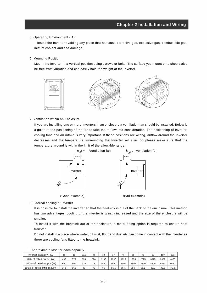
6. Mounting Position
Mount the Inverter in a vertical position using screws or bolts. The surface you mount onto should also
be free from vibration and can easily hold the weight of the Inverter.
7. Ventilation within an Enclosure
If you are installing one or more Inverters in an enclosure a ventilation fan should be installed. Below is
a guide to the positioning of the fan to take the airflow into consideration. The positioning of Inverter,
cooling fans and air intake is very important. If these positions are wrong, airflow around the Inverter
decreases and the temperature surrounding the Inverter will rise. So please make sure that the
temperature around is within the limit of the allowable range.
8.External cooling of Inverter
It is possible to install the inverter so that the heatsink is out of the back of the enclosure. This method
has two advantages, cooling of the inverter is greatly increased and the size of the enclosure will be
smaller.
To install it with the heatsink out of the enclosure, a metal fitting option is required to ensure heat
transfer.
Do not install in a place where water, oil mist, flour and dust etc can come in contact with the inverter as
there are cooling fans fitted to the heatsink.
9. Approximate loss for each capacity
Inverter capacity (kW) 11 15 18.5 22 30 37 45 55 75 90 110 132
70% of rated output (W) 435 575 698 820 1100 1345 1625 1975 2675 3375 3900 4670
100% of rated output (W) 600 800 975 1150 1550 1900 2300 2800 3800 4800 5550 6650
100% of rated efficiency(%) 94.8 94.9 95 95 95 95.1 95.1 95.1 95.2 95.2 95.2 95.2
Chapter 2 Installation and Wiring
(Good example) (Bad example)
Ventilation fan
Inverter
Ventilation fan
Inverter

2-4
2.1.2 Blind cover of wiring parts (11 to 75kW)(1) Cable entry through Rubber Bushes
The wiring should be done after making a cut in the rubber bushes with nippers or cutters.
(2) Cable entry through Conduit
After taking out the rubber bushes, connect the conduit.
(Note) Except for when connecting conduit, Do not take out the rubber bushes. It is possible that the
wiring insulation is broken and a possible earth fault is caused.
Chapter 2 Installation and Wiring
Rubber bushes
Wiring
cover

2-5
2.2 Wiring
• Be sure to ground the unit.Otherwise, there is a danger of electric shock and/or fire.
• Wiring work shall be carried out by electrical experts.Otherwise, there is a danger of electric shock and/or fire.
• Implement wiring after checking that the power supply is off.It might incur electric shock and/or fire.
• After installing the main body, carry out wiring.Otherwise, there is a danger of electric shock and/or injury.
• Do not remove the rubber bush. (11 to 75kW)Due to the possibility that a wire may be damaged, shorted or may have a ground fault with the edgeof the wiring cover.
• Make sure that the input voltage is:Three phase 200 to 240V 50/60Hz (for models with suffix L)Three phase 380 to 480V 50/60Hz (for models with suffix H)
• Be sure not to input a single phase.Otherwise, there is a danger of fire.
• Be sure not to connect AC power supply to the output terminals(U, V, W).Otherwise, there is a danger of injury and/or fire.
• Be sure not to connect the resistor to DC terminals (PD,P and N) directly.Otherwise, there is a danger of fire.
• Be sure to set the earth leakage breaker or the fuse(s) (the same phase as the main power supply) in theoperation circuit.
Otherwise, there is a danger of fire.
• As for motor leads, earth leakage breakers and electromagnetic contactors, be sure to use theequivalent ones with the specified capacity (rated).
Otherwise, there is a danger of fire.
• Do not stop operation by switching off the electromagnetic contactors on the primary or secondary sidesof the inverter.
Otherwise, there is a danger of injury and/or machine breakage.
• Fasten the screws with the specified fastening torque. Check so that there is no loosening of screws.Otherwise, there is a danger of fire.
Chapter 2 Installation and Wiring
WARNING
CAUTION
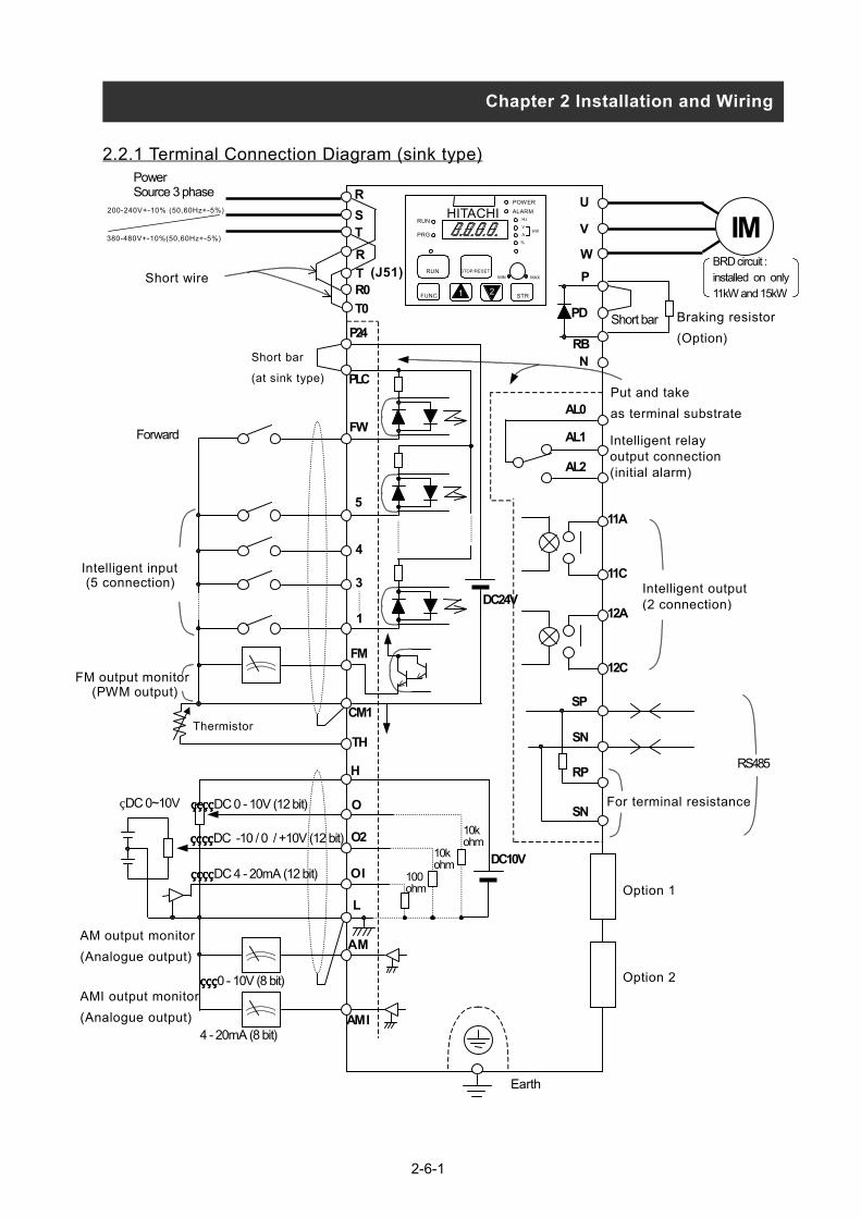
2.2.1 Terminal Connection Diagram (sink type)
Chapter 2 Installation and Wiring
FM output monitor (PWM output)
Intelligent input (5 connection)
Power
Intelligent relayoutput connection(initial alarm)
BRD circuit :installed on only11kW and 15kW
R
ST
R0
T0
U
V
W
P
PD
B
PLC
P24
FW
4
3
1
5
FM
CM1
TH
H
O
O2
O I
L
AM
DC24V
SP
SN
RP
SN
RS485
Put and take
as terminal substrate
Short bar
Short bar
(at sink type)
Forward
DC 0 - 10V (12 bit)
DC 4 - 20mA (12 bit)
DC -10 / 0 / +10V (12 bit)
1 2
HITACHI
A
%
kW
MIN MAX
PRG
DC10V100ohm
10kohm
10kohm
11A
11C
12C
R
T (J51)
AM output monitor
(Analogue output)
2-6-1
E
AM I
0 - 10V (8 bit)
4 - 20mA (8 bit)
H
V
Option 2
AMI output monitor
(Analogue output)
DC 0~10V
arth
Intelligent output(2 connection)
RN
IM
Option 1
For terminal resistance
AL0
AL1
AL2
Braking resistor
(Option)
Thermistor
Source 3 phase200-240V+-10% (50,60Hz+-5%)
380-480V+-10%(50,60Hz+-5%)
POWER
ALARM
z RUNRUN
FUNC
STRSTOP/RESET
12A
Short wire

2-6-2
2.2.1 Terminal Connection Diagram (source type)
Chapter 2 Installation and Wiring
FM output monitor (PWM output)
AM output monitor
(Analogue output)
Intelligent input (5 connection)
AMI output monitor
(Analogue output)
PowerSource 3 phase
Intelligent relayoutput connection(initial alarm)
Earth
DC 0~10V
Intelligent output(2 connection)
R
ST
R0
T0
U
V
W
P
PD
RBN
IM
PLC
CM1
P24
FW
4
3
1
5
FM
CM1
TH
H
O
O2
O I
L
AM
AM I
DC24V
SP
SN
RP
SN
Option 1
Option 2
For terminal resistance
RS485
Put and take
as terminal substrateAL0
AL1
AL2
Braking resistor
(Option)Short bar
Short bar
Forward
Thermistor
0 - 10V (8 bit)
DC 0 - 10V (12 bit)
DC 4 - 20mA (12 bit)
DC -10 / 0 / +10V (12 bit)
200-240V+-10% (50,60Hz+-5%)
380-480V+-10%(50,60Hz+-5%)
1 2
HITACHIPOWER
ALARMHz
V
A
%
kW
MIN MAX
RUN
PRG
RUN
FUNC STR
STOP/RESET
DC10V100ohm
10kohm
10kohm
4 - 20mA (8 bit)
11A
11C
12A
12C
R
T (J51)Short wire
(at source type)
BRD circuit :installed on only11kW and 15kW
Mo
nit
or
Dig
ita
l (c
on
ne
ctio
n)
Po
we
r eF
req
ue
nc
y s
ett
ing
Op
era
tio
n/f
un
ctio
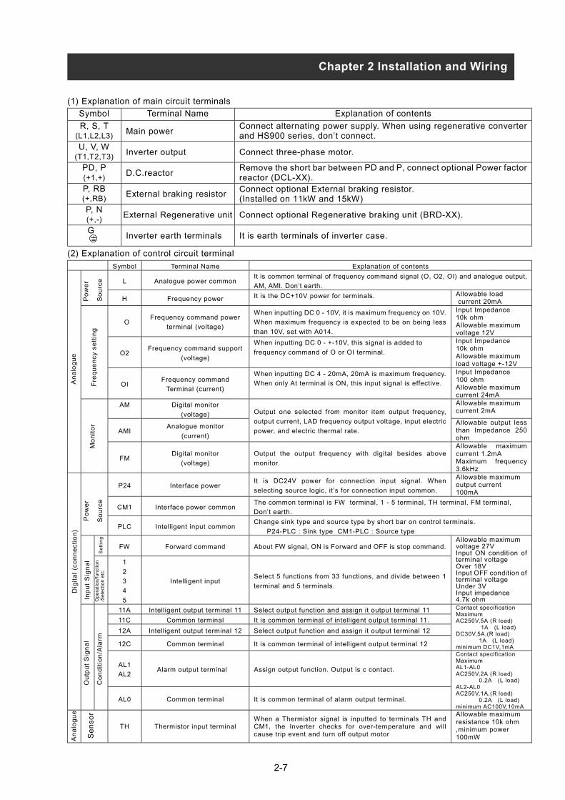
n(1) Explanation of main circuit terminals
Symbol Terminal Name Explanation of contents
R, S, T(L1,L2,L3)
Main powerConnect alternating power supply. When using regenerative converterand HS900 series, don’t connect.
U, V, W(T1,T2,T3)
Inverter output Connect three-phase motor.
PD, P(+1,+)
D.C.reactorRemove the short bar between PD and P, connect optional Power factorreactor (DCL-XX).
P, RB(+,RB)
External braking resistorConnect optional External braking resistor.(Installed on 11kW and 15kW)
P, N(+,-)
External Regenerative unit Connect optional Regenerative braking unit (BRD-XX).
GInverter earth terminals It is earth terminals of inverter case.
(2) Explanation of control circuit terminal
Symbol Terminal Name Explanation of contents
It is common terminal of frequency command signal (O, O2, OI) and analogue output,
Chapter 2 Installation and Wiring
A
na
log
ue
Po
we
rIn
pu
t S
ign
al
Ou
tpu
t S
ign
al
Se
nso
r
An
alo
gu
e
2-7
So
urc
/Se
lect
ion
etc
.
L Analogue power commonAM, AMI. Don’t earth.
H Frequency power It is the DC+10V power for terminals. Allowable load current 20mA
OFrequency command power
terminal (voltage)
When inputting DC 0 - 10V, it is maximum frequency on 10V.
When maximum frequency is expected to be on being less
than 10V, set with A014.
Input Impedance10k ohmAllowable maximumvoltage 12V
O2Frequency command support
(voltage)
When inputting DC 0 - +-10V, this signal is added to
frequency command of O or OI terminal.
Input Impedance10k ohmAllowable maximumload voltage +-12V
OIFrequency command
Terminal (current)
When inputting DC 4 - 20mA, 20mA is maximum frequency.
When only At terminal is ON, this input signal is effective.
Input Impedance100 ohmAllowable maximumcurrent 24mA
AM Digital monitor
(voltage)
Allowable maximumcurrent 2mA
AMIAnalogue monitor
(current)
Output one selected from monitor item output frequency,
output current, LAD frequency output voltage, input electric
power, and electric thermal rate.Allowable output lessthan Impedance 250ohm
FMDigital monitor
(voltage)
Output the output frequency with digital besides above
monitor.
Allowable maximumcurrent 1.2mAMaximum frequency3.6kHz
P24 Interface powerIt is DC24V power for connection input signal. When
selecting source logic, it’s for connection input common.
Allowable maximumoutput current100mA
CM1 Interface power commonThe common terminal is FW terminal, 1 - 5 terminal, TH terminal, FM terminal,
Don’t earth.
PLC Intelligent input commonChange sink type and source type by short bar on control terminals.
P24-PLC : Sink type CM1-PLC : Source type
FW Forward command About FW signal, ON is Forward and OFF is stop command.
1
2
3
4
5
Intelligent inputSelect 5 functions from 33 functions, and divide between 1
terminal and 5 terminals.
Allowable maximumvoltage 27VInput ON condition ofterminal voltageOver 18VInput OFF condition ofterminal voltageUnder 3VInput impedance4.7k ohm
11A Intelligent output terminal 11 Select output function and assign it output terminal 11
11C Common terminal It is common terminal of intelligent output terminal 11.
12A Intelligent output terminal 12 Select output function and assign it output terminal 12
12C Common terminal It is common terminal of intelligent output terminal 12
Contact specificationMaximumAC250V,5A (R load) 1A (L load)DC30V,5A,(R load) 1A (L load)minimum DC1V,1mA
AL1
AL2 Alarm output terminal Assign output function. Output is c contact.
AL0 Common terminal It is common terminal of alarm output terminal.
Contact specificationMaximumAL1-AL0AC250V,2A (R load) 0.2A (L load)AL2-AL0AC250V,1A,(R load) 0.2A (L load)minimum AC100V,10mA
TH Thermistor input terminalWhen a Thermistor signal is inputted to terminals TH andCM1, the Inverter checks for over-temperature and willcause trip event and turn off output motor
Allowable maximumresistance 10k ohm,minimum power100mW
Se
ttin
gS
ou
rce
Co
nd
itio
n/A
larm

2-8
2.2.2 Main circuit wiring(1) Warning on wiring
When carrying out work on the Inverter wiring make sure to wait for at least ten minutes before youremove the cover. Making sure to check that the charge lamp is not illuminated. A final check shouldalways be made with a voltage meter. After removing the power supply, there is a time delay before thecapacitors will dissipate their charge.
1. Main power terminals(R, S, T)• Connect the main power terminals (R, S, and T) to the power supply through a electromagnetic contactoror an earth-leakage breaker.
• We recommend connecting the electromagnetic contactor to the main power terminals. Because when theprotective function of inverter operates, it isolates the powers supply and prevent the spread of damagesand accidents.
• This unit is for the three-phase power supply. It isn’t for the single-phase power supply. If you require asingle-phase power supply unit, please contact us.
• Don't operate with on/off of the switch set up in the converter side and the inverter side. Do an operationstop by the operation order (FW/RV) terminals
• This inverter becomes the following condition at the time of open phase because open phase protectionis being made ineffective by the early data.
R phase or T phase, open phase condition: The power isn't turned on, and it doesn't operate.S phase, open phase condition: It becomes single-phase operation condition. Trip operation such as a
deficiency voltage or over current may be done.Don't use it under open phase condition.
• A converter module may be damaged in the case shown below. Be careful.When an unbalance of the power supply voltage is more than 3%.Power supply capacity, 10 times of the capacity of inverter and a case beyond 500kVA.When a change in the rapid power supply voltage occur.
(Example) When inverter of the plural is installed with the common electric wire whose it is short byeach other.When there is insertion of the condenser or a removal.
• On/off of the power supply isn't to do it more than three times in one minute. It has the possibility thatinverter is damaged.
2. Inverter output terminals (U, V, and W)• Wire with thicker wire than the applicable wire to control the voltage drop. Particularly when outputtinglow frequencies, the torque of the motor will reduce by the voltage drop of the wire.
• Do not install power factor correction capacitors or a surge absorber to the output. The inverter will trip orsustain damage to the capacitors or the surge absorber.
• In the case of the cable length being more than 20 meters, it is possible that a surge voltage will begenerated and damage to the motor is caused by the floating capacity or the inductance in the wire (400Vespecially). An EMC Mains Filter is available, please contact us.
• In the case of two or more motors, install a thermal relay to each motor.• Make the RC value of the thermal relay the value of 1.1 times of motor rated electric current. Install outputACL when a life becomes short by the length of wiring.
3. Direct current reactor (DCL) connection terminals (PD, P)• These are the terminals to connect the current reactor DCL (Option) to help improve the power factor.• The short bar is connected to the terminals when shipped from the factory, if you are to connect a DCL you
Chapter 2 Installation and Wiring
2-9
will need to disconnect the short bar first.• When you don’t use a DCL, don’t disconnect the short bar.
4. External braking resistor connection terminals (P, RB)• The regenerative braking circuit (BRD) is built-in as standard up to the 15kW Inverter. When braking isrequired, install an external-braking resistor to these terminals.
• The cable length should be less than 5 meters, and twist the two connecting wires to reduce inductance.• Don’t connect any other device other than the external braking resistor to these terminals.• When installing an external braking resistor make sure that the resistance is correctly rated to limit thecurrent drawn through the BRD.
5. Regenerative breaking unit connection terminals (P, N)• The Inverters rated more than 18.5kW don’t contain a BRD circuit. If regenerative braking is required anexternal BRD circuit (Option) is required along with the resistor (Option).
• Connect external regenerative braking unit terminals (P, N) to terminals (P,N) on the inverter. The brakingresistor is then wired into the External Braking unit and not directly to the Inverter.
• The cable length should be less than 5 meters, and twist the two connecting wires to reduce inductance.
6. Earth (G )• Make sure that you securely ground the Inverter and motor for prevention of electric shock.• The inverter and motor must be connected to an appropriate safety earth and follow the local standard.
Failure to do so constitutes an electrical shock hazard.
Chapter 2 Installation and Wiring

2-10
(2) Wiring of main circuit terminalsThe wiring of main circuit terminals for inverter is the following picture.
Wiring of terminals Corresponding typeL300P-110,150LF/HF
R0-T0 : M4Other : M6
L300P-185LFL300P-185-370HF
R0-T0 : M4Other : M6
L300P-370LFL300P-450,550,750HF
R0-T0 : M4Other : M8
L300P-220,300LF
R0-T0 : M4Earth terminal : M6Other : M8
L300P-450,550LF
R0-T0 : M4Earth terminal : M6Other : M10
L300P-750LFL300P-900-1320HF
R0-T0 : M4Earth terminal : M8Other : M10
Chapter 2 Installation and Wiring
W(T3)
R(L1)
PD(+1)
S(L2)
T(L3)
U(T1)
V(T2)
P(+)
N(-)
RB G G
R0 T0
Charge lamp
Short bar
R(L1)
S(L2)
T(L3)
PD(+1)
P(+)
N (-)
U(T1)
V(T2)
W(T3)G G
Short bar
R0 T0
Charge lamp
R(L1)
S(L2)
T(L3)
PD(+1)
P(+)
N(-)
U(T1)
V(T2)
W(T3)
R0 T0
Short bar
Charge lamp
R(L1)
S(L2)
T(L3)
PD(+1)
P(+)
N(-)
U(T1)
V(T2)
W(T3)
R0 T0
Short bar
Charge lamp

2-11
Input recontrol,elecpower-facto(ALI-***)Radio noise
reactor) (Z
Noise filter(NF-***)
Input radio (capacitor fDirect reac
Breaking reRegenerati
Output nois
Radio noisreactor) (ZC
Output alterReducing relay, preve(ACL-*-**)
LCR filter
(3) Wiring Equipment
Refer to “(4) Common applicable tools”
(Note 1) The applicable tools indicate for Hitachi standard four-pole squirrel-
cage Motor.
(Note 2) Select applicable tools for breakers examining the capacity of
breakers.(Use Inverter type.)
(Note 3) Use earth-leakage breakers (ELB) for safety.
(Note 4) Use 60/75ºC copper electric wire.
(Note 5) It needs bigger wires for power lines, if the distance exceeds 20m.
(Note 6) 0.75mm2 for Alarm output contact.
(Note 7) Separate by the sum wiring distance from Inverter to power supply,
from inverter to motor for the sensitive current of leak breaker (ELB).
(Note 8) When using CV wire and wiring by rigid metal conduit, leak flows.
(Note 9) IV wire is high dielectric constant. So the current increase 8 times.
Therefore, use the sensitive current 8
times as large as that of the left list. And if
the distance of wire is over 100m, use CV
wire.
Chapter 2 Installation and WiringChapter 2 Installation and Wiring
Electricconductor
ELB
RB
R S T
U V W
PD
P
N
R0
T0 Inve
rte
r
Motor
IM
Power supply
100
300
Wiringdistance
Sensitive
Current(mA)
m and less 50
m and less 100
Name Functionactor (harmonictrical coordination,r improvement)
This part is used when the unbalance voltage rate is 3% or more and
power supply is 500 kVA or more, and there is a rapid change in the
power supply. It also improves the power factor.
filter (zero-phase
CL-***)(FC-**)
Using the inverter may cause noise on the peripheral radio through the
power lines. This part reduces noise.
for InverterThis part reduces common noise generated between the power supply
and the ground, as well as normal noise. Put it in the primary side of
inverter.
noise filterilter) (CFI-*)
This part reduces radiation noise emitted from wire at the input.
tor (DCL-*-**) This part control harmonic from inverter.
sistorve breaking unit
This part is used for applications that need to increase the brake
torque of the inverter or to frequently turn on and off and to run high
inertia load.
e filter (ACF-C*)This part reduces radiation noise emitted from wire by setting between
inverter and motor. And it reduces wave fault to radio and TV, it is used
for preventing malfunction of sensor and measuring instruments.
e filter(zero-phaseL-***)
This part reduces noise generated at the output of the inverter. (It is
possible to use for both input and output.)
nation reactorvibration, Thermalnting misapplication
Running motors with the inverter generates vibration greater than that
with commercial power supply. This part installed between the inverter
and motor reduces torque ripple. When the cable length between the
inverter and motor is long (10m or more), a countermeasure for a
malfunction of the thermal relay by harmonic due to switching on
inverter is taken by inserting reactor.
There is the way to use current sensor in stead of thermal relay.
Sine-wave filter at the output.

2-12
(4) Common applicable tools
Power linesR,S,T,U,V,W,P,PD,N
Earth lineG
ExternalresisterbetweenP and RB
Applicable tools
Motor
Output
(kW)
ApplicableInvertermodel mm2
ormore
AWG
or
more
mm2
ormore
AWG
or
more
AWG
or
more
(#5)
mm2 AWG
Screw
size of
terminal
Terminal
Tightning
Torque
max
(N•m) Leak breaker(ELB)
Circuit
breaker
or fuse
Electro-
magnetic
controller
(Mg)
11 L300P-110LF 14 4 14 4 10 5.5 8 M6 14-6 4.9 RX100(75A) 60A H50
15 L300P-150LF22
(Note 1)2 22 3 8 5.5 8 M6 22-6 4.9 RX100(100A) 70A H65
18.5 L300P-185LF 30 1 22 3 8 - - M6 38-6 4.9 RX100(100A) 90A H80
22 L300P-220LF 38 1/0 30 2 8 - - M8 38-8 8.8 RX225B(150A) 100A H100
30 L300P-300LF60
(Note 1)2/0 30 2 6 - - M8 60-8 8.8 RX225B(200A) 150A H125
37 L300P-370LF100
(38×2)(Note 1)
(#1) 50 1/0 6 - - M8100-8(38-8)
8.8 RX225B(225A) 175A H150
45 L300P-450LF100
(38×2)(#2) 80 3/0 6 - - M10
100-10(38-10)
13.7 RX225B(225A) 200A H200
55 L300P-550LF150
(60×2)(Note 1)
(#3) 80 3/0 4 - - M10150-10(60-10)
13.7 RX400B(350A) 250A H250
20
0V
cla
ss
75 L300P-750LF150
(60×2)(Note 1)
(#3) 100 4/0 4 - - M10150-10(60-10)
13.7 RX400B(350A) 300A H300
11 L300P-110HF 5.5 8 5.5 8 10 5.5 8 M6 5.5-6 4.9 EX50C(50A) 30A H25
15 L300P-150HF 8 6 8 8 10 5.5 8 M6 8-6 4.9 EX60B(60A) 35A H35
18.5 L300P-185HF 14 6 14 4 10 - - M6 14-6 4.9 EX60B(60A) 50A H50
22 L300P-220HF 14 4 14 4 10 - - M6 14-6 4.9 RX100(75A) 50A H50
30 L300P-300HF 22 3 22 3 10 - - M6 22-6 4.9 RX100(100A) 70A H65
37 L300P-370HF 38 1 22 3 8 - - M6 38-6 4.9 RX100(100A) 80A H80
45 L300P-450HF 38 1 22 1 8 - - M8 38-8 8.8 RX225B(150A) 100A H100
55 L300P-550HF 60 1/0 30 1 6 - - M8 60-8 8.8 RX225B(175A) 125A H125
75 L300P-750HF100
(38×2) (#2)50 1/0 6 - - M8
100-8(38-8)
8.8 RX225B(225A) 150A H150
90 L300P-900HF 38×2 (#2) 50 3/0 6 - - M10 38-10 13.7 RX225B(225A) 200A H200
110L300P-1100HF
60×2 (#3) 80 3/0 4 - - M10 60-10 13.7 RX400B(350A) 250A H250
40
0V
cla
ss
132L300P-1320HF
80×2 (#3) 100 4/0 4 - - M10 80-10 13.7 RX400B(350A) 300A H300
#1 3/0 or 2 parallel of 1 AWG #2 250kcmil or 2 parallel of 1 AWG(75ºC) #3 350kcmil or 2 parallel of 1/0 AWG
#4 Use suitable fuse with an UL-listed for UL. #5 Conformity to the UL
(Note) Field wiring must be made by an UL-listed and CSA-certified closed-loop terminal connector sized for
the wire gauge involved. Connector must be fixed by using the crimping tool specified by the connector
manufacture or equivalent wording included in the manual.
(Note 1) If wires are shorter than 10m and are located within an enclosure, it is possible to use following power
lines.
Power lines
InverterModel
mm2
ormore
AWG or
more
Heatresistant
Terminal
150LF 14 4 110ºC 14-6
300LF 38 1/0 110ºC 38-8
370LF 60 2/0 110ºC 60-8
550LF,750LF 100 (#2) 110ºC 100-10
Chapter 2 Installation and WiringChapter 2 Installation and Wiring
2-13
Use suitable circuit breaker or fuse listed in this manual for UL’s listing purpose.
Otherwise, there is a danger of fire.
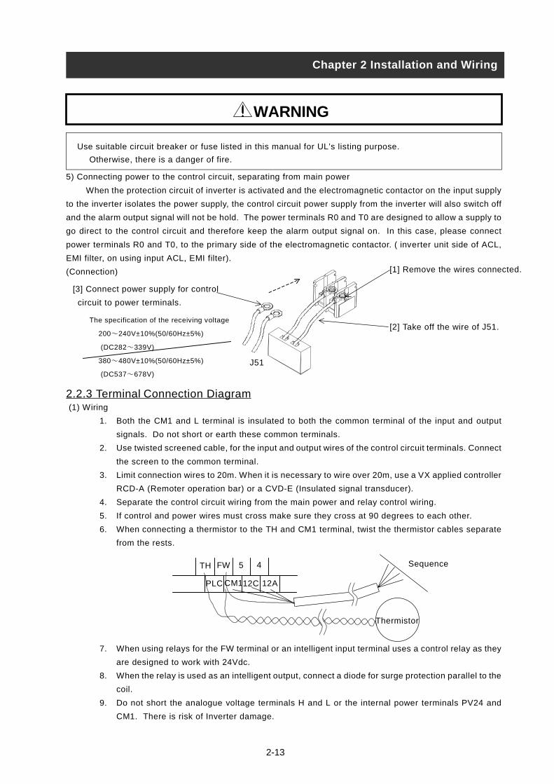
5) Connecting power to the control circuit, separating from main power
When the protection circuit of inverter is activated and the electromagnetic contactor on the input supply
to the inverter isolates the power supply, the control circuit power supply from the inverter will also switch off
and the alarm output signal will not be hold. The power terminals R0 and T0 are designed to allow a supply to
go direct to the control circuit and therefore keep the alarm output signal on. In this case, please connect
power terminals R0 and T0, to the primary side of the electromagnetic contactor. ( inverter unit side of ACL,
EMI filter, on using input ACL, EMI filter).
(Connection)
2.2.3 Terminal Connection Diagram (1) Wiring
1. Both the CM1 and L terminal is insulated to both the common terminal of the input and output
signals. Do not short or earth these common terminals.
2. Use twisted screened cable, for the input and output wires of the control circuit terminals. Connect
the screen to the common terminal.
3. Limit connection wires to 20m. When it is necessary to wire over 20m, use a VX applied controller
RCD-A (Remoter operation bar) or a CVD-E (Insulated signal transducer).
4. Separate the control circuit wiring from the main power and relay control wiring.
5. If control and power wires must cross make sure they cross at 90 degrees to each other.
6. When connecting a thermistor to the TH and CM1 terminal, twist the thermistor cables separate
from the rests.
7. When using relays for the FW terminal or an intelligent input terminal uses a control relay as they
are designed to work with 24Vdc.
8. When the relay is used as an intelligent output, connect a diode for surge protection parallel to the
coil.
9. Do not short the analogue voltage terminals H and L or the internal power terminals PV24 and
CM1. There is risk of Inverter damage.
TH 45FW
PLC CM112C 12A
Thermistor
Sequence
[2] Take off the wire of J51.
[1] Remove the wires connected.
[3] Connect power supply for control
circuit to power terminals.
J51
WARNING
The specification of the receiving voltage
200~240V±10%(50/60Hz±5%)
(DC282~339V)
380~480V±10%(50/60Hz±5%)
(DC537~678V)
Chapter 2 Installation and Wiring

2-14
(2) Layout of control circuit terminals
H O2 AM FM TH FW 5 4 3 2 1 AL1
L O OI AMI P24 PLC CM1 12C 12A 11C 11A ALO AL2
(3)Change of input logic type
The logic type of intelligent input terminals is sink type (Factory Default). To change the input logic type
into source type, take off the short bar between P24 and PLC on the control terminal and connect it
between PLC and CM1.
(4) The connection to the input programmable logic controller (sequencer)
To use interface power within inverter To use outside power (Take off the short bar of control terminal.)
Chapter 2 Installation and WiringS
ou
rce
typ
e
DC24V
InverterYTS48 type
Output module
S
COM P24
PLC
CM1
FW
5
Shortbar
DC24VDC24V
COM
S
P24
PLC
CM1
InverterYTS48 type
Output module
FW
5
The terminal screw size; M3
Sin
k ty
pe
DC24V
InverterYTR48 type
Output module
Shortbar
S
COM
P24
PLC
CM1
FW
5
DC24V
P24
PLC
CM1
FW
S
DC24V
CO
InverterYTR48 type
Output module
5

2-15
2.2.4 Digital operator wiring
For operating this inverter, it can use digital operator OPE-SR , OPE-SRE, OPE-S, SRW-0J and SRW-0EX.
For remote operating, put off digital operator from inverter and use connector cable ICS-1(1m) or ICS-
3(3m).
(Note 1) When using connector cable, be sure to use less than 3m length. Otherwise, there is a danger of
malfunction.
(Note 2) In case of remote operating with connector cable, the inverter does not conform to EMC.
Chapter 2 Installation and Wiring

3-1
• Be sure not to touch the main terminal or to check the signal or put on/off wire and/or connector.Otherwise, there is a danger of electric shock.
• Be sure to turn on the input power supply after closing the front cover.While being energized, be sure not to open the front cover.
Otherwise, there is a danger of electric shock.
• Be sure not to operate the switches with wet hands.Otherwise, there is a danger of electric shock.
• While the inverter is energized, be sure not to touch the inverter terminals even during stoppage.Otherwise, there is a danger of electric shock.
• If the retry mode is selected, it may suddenly restart during the trip stop. Be sure not to approach the machine.(Be sure to design the machine so that personnel safety will be secured even if it restarts.)
Otherwise, there is a danger of injury.
• Be sure not to select retry mode for up and down equipment or traveling equipment, because there is outputfree-running mode in term of retry.
Otherwise, there is a danger of injury and/or machine breakage.
• Even if the power supply is cut for a short period of time, it may restart operation after the power supply isrecovered if the operation command is given. If it may incur danger to personnel, be sure to make a circuit sothat it will not restart after power recovery.
Otherwise, there is a danger of injury.
• The Stop Key is effective only when the function is set. Be sure to prepare the Key separately from theemergency stop.
Otherwise, there is a danger of injury.
• After the operation command is given, if the alarm reset is conducted, it will restart suddenly. Be sure to set thealarm reset after checking the operation command is off.
Otherwise, there is a danger of injury.
• Be sure not to touch the inside of the energized inverter or to put a bar into it.Otherwise, there is a danger of electric shock and/or fire.
WARNING
Chapter 3 Operation
3-2
• Cooling fin will have high temperature. Be sure not to touch them.Otherwise, there is a danger of getting burned.
• Low to high speed operation of the inverter can be easily set. Be sure to operate it after checking the tolerance
of the motor and machine.Otherwise, there is a danger of injury.
• Install external break system if needed.Otherwise, there is a danger of injury.
• If a motor is operated at a frequency higher than standard setting value(50Hz/60Hz),be sure to check the
speeds of the motor and the machine with each manufacturer, and after getting their consent, operate them.Otherwise, there is a danger of machine breakage.
• Check the following before and during the test run.
Otherwise, there is a danger of machine breakage.
Was the direction of the motor correct?
Was the inverter tripped during acceleration or deceleration?
Were the rpm and frequency meter correct?Were there any abnormal motor vibrations or noise?
CAUTION
Chapter 3 Operation

3-3
3.1 Operation
This inverter requires two different signals in order for the Inverter to operate correctly. The Inverter requires
both an operation setting and a frequency setting.
The following indicates the details of each method of operation and the necessary instructions for operation.
(1) Operation setting and a frequency setting by the terminal control.
This is the method by connecting signals from the outside (the frequency setting, the starting switch etc.)
with the control circuit terminals.
The operation is started when the operation setting (FW, RV) is turned ON while the input power is turned
ON.
(Note) The methods of the setting frequency with terminal are the voltage setting and the electric setting.
And they are selective by each system. The control circuit terminal list shows this in detail.
(Necessary things for operation)
[1] The operation setting: switch, relay etc.
[2] The frequency setting: signals from volume or external (DC0-10V, DC-10-10V, 4-20mA etc.)
(2) Operation setting and frequency setting with the digital operator.
This is the method for operation from the digital operator, which comes equipped with the inverter as
standard, or the remote operator (SRW) keypad.
When the digital operator sets the operation, the terminals (FW, RV) don’t need to be linked.
And it is possible to select frequency from the digital operator as a method of the frequency setting too.
(Necessary things for operation)
[1] Remote Operator (SRW) (It’s unnecessary in case of digital operator operation)
(3) Operation setting and frequency setting from both digital operator and terminal operator
This is the method of inverter operating from both of the above two operating methods
It is possible that the operation setting and the frequency setting can be selected for both the digital
operator and the terminal operator each separately.
Chapter 3 Operation
Power Lamp
Digital Operator
Volume
Terminal
Operation Setting (switch)Frequency setting (volume)
3-4
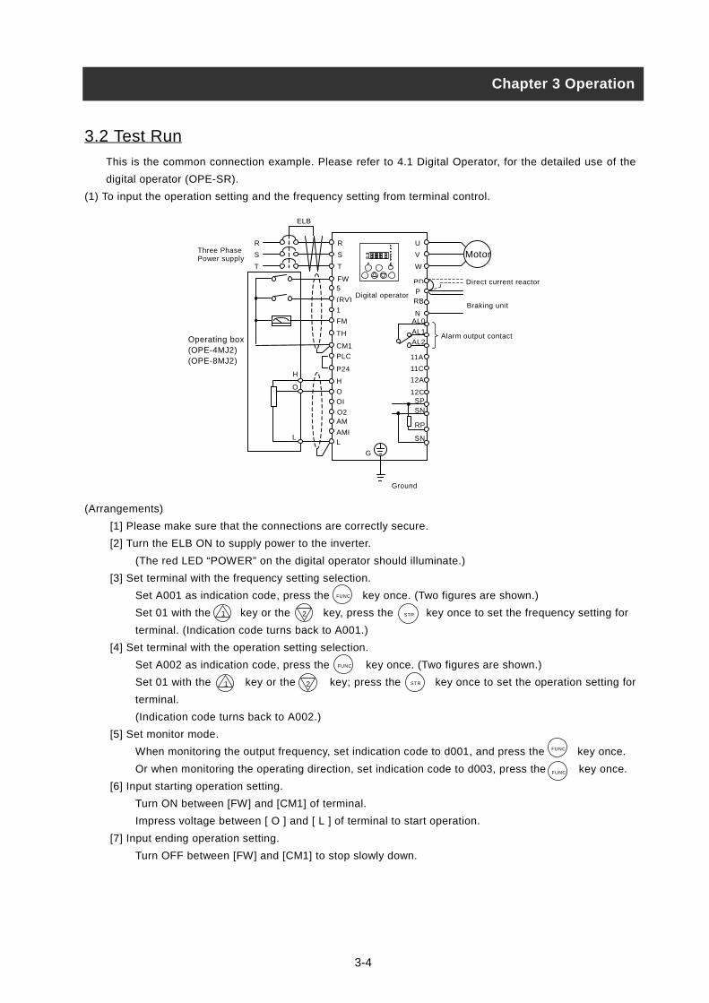
3.2 Test Run
This is the common connection example. Please refer to 4.1 Digital Operator, for the detailed use of the
digital operator (OPE-SR).
(1) To input the operation setting and the frequency setting from terminal control.
(Arrangements)
[1] Please make sure that the connections are correctly secure.
[2] Turn the ELB ON to supply power to the inverter.
(The red LED “POWER” on the digital operator should illuminate.)
[3] Set terminal with the frequency setting selection.
Set A001 as indication code, press the key once. (Two figures are shown.)
Set 01 with the key or the key, press the key once to set the frequency setting for
terminal. (Indication code turns back to A001.)
[4] Set terminal with the operation setting selection.
Set A002 as indication code, press the key once. (Two figures are shown.)
Set 01 with the key or the key; press the key once to set the operation setting for
terminal.
(Indication code turns back to A002.)
[5] Set monitor mode.
When monitoring the output frequency, set indication code to d001, and press the key once.
Or when monitoring the operating direction, set indication code to d003, press the key once.
[6] Input starting operation setting.
Turn ON between [FW] and [CM1] of terminal.
Impress voltage between [ O ] and [ L ] of terminal to start operation.
[7] Input ending operation setting.
Turn OFF between [FW] and [CM1] to stop slowly down.
1 2
1 2
Chapter 3 Operation
FUNC
STR
FUNC
FUNC
FUNC
Direct current reactor
Operating box(OPE-4MJ2)(OPE-8MJ2)
Alarm output contact
L
O
H
MotorU
V
W
PDPRB
NAL0
AL1
AL2
11A
11C
12C
12A
SPSN
RP
SN
G
AMI
AM
L
O2
OI
O
H
P24
PLC
CM1
TH
FM
1
5FW
R
S
T
Braking unit
R
S
T
Three PhasePower supply
ELB
Digital operator(RV)
Ground
STR
3-5
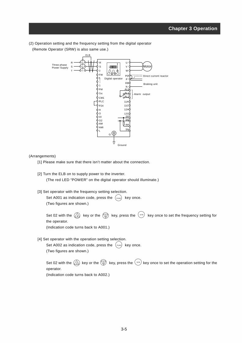
(2) Operation setting and the frequency setting from the digital operator
(Remote Operator (SRW) is also same use.)
(Arrangements)
[1] Please make sure that there isn’t matter about the connection.
[2] Turn the ELB on to supply power to the inverter.
(The red LED “POWER” on the digital operator should illuminate.)
[3] Set operator with the frequency setting selection.
Set A001 as indication code, press the key once.
(Two figures are shown.)
Set 02 with the key or the key, press the key once to set the frequency setting for
the operator.
(Indication code turns back to A001.)
[4] Set operator with the operation setting selection.
Set A002 as indication code, press the key once.
(Two figures are shown.)
Set 02 with the key or the key, press the key once to set the operation setting for the
operator.
(Indication code turns back to A002.)
Chapter 3 Operation
1 2
1 2
Direct current reactor
Ground
ELB
MotorU
V
W
PDP
RB
NAL0
AL1
AL2
11A
11C
12C
12A
SPSN
RP
SN
G
AMI
AM
L
O2
OI
O
H
P24
PLC
CM1
TH
FM
1
5FW
R
S
T
Braking unit
R
S
T
Three phasePower Supply
Alarm output
----
Digital operator
FUNC
FUNC
STR
STR

[5] Set the output frequency
Set F001 as indication code, as press the key once.
(Indication code of four figures is shown.)
Set to the desired output frequency with the key or the key, press the key once to
store it.
(Indication code turns back to F001.)
[6] Set the operation direction.
Set F004 as indication code, press th
(00 or 01 is shown.)
Set operation direction to 00 i case
key or the key. Press the
(Indication code turns back to F004.)
[7] Set monitor mode.
When monitoring the output frequenc
Or when monitoring the operation dir
(Indication code are forward,
[8] Press the key to start operating.
(The green LED “RUN” turns on a lig
set.)
[9] Press the key to decelerate to a s
(When the frequency turn back to 0,
Make sure that the direction of the motor is c
Make sure there is no abnormal noise and vi
Make sure that there is no tripping during
per minute and the frequency meter are co
When overcurrent tripping or overvoltage tr
or the deceleration time.
1 2
1 2
RUN
Chapter 3 Operation
RESETSTOP/
FUNC
STR
e key once.
of forward, or to 01 in case of reverse with the
FUNC
n
3-6
key once to establish it.
y, set indication code to d001, and press the key once.
ection, set indication code to d003, press the key once.
reverse or stop.)
ht, and the indication changes in response to the monitor mode
top.
the green LED “RUN” light will switch off.)
orrect. It is in danger of injury or machine damage.
bration. It is in danger of injury or machine damage.
the acceleration and deceleration and check that the revolution
rrect.
ipping occurs during the test run, increase the acceleration time
FUNC
FUNC
STR
CAUTION

4-1
4.1 About Digital Operator (OPE-SR)
Explanation of operating the digital operator (OPE-SR)
L300P series operates by using the digital operator, which is fitted as standard.
1. Name and contents of each part of the digital operator
Name ContentsMonitor Display of frequency, output current and set valueLamp on RUN (Operation)
Light on when the inverter is running
Program lamp Light on when displaying set value of each function in monitor sectionLight will flash On and Off as a warning (when set value is incorrect)
POWER lamp Power lamp of control circuitALARM lamp Light on when the Inverter trips
Monitor lampLamp display state of monitor section.Hz : Frequency V : Voltage A : Current kW : Electric power % : Rate
Volume lamp Light on when the frequency can be set by the volume for frequency settingOperation commandDisplay lamp
Light on only when operating command (RUN/STOP) is set in operator
RUN keyRun command to start the motor. But this is only valid when operation command isfrom the operator. (Be sure that the operation command display lamp is illuminated.)
STOP (STOP/RESET) key This key is used to stop motor, or reset an alarm.Volume for frequency setting
This can be used to set the output frequency. But this is only valid when the frequencycommand part is set in volume.
FUNC (Function) key The key containing monitor mode, basic setting mode, extension functions mode.STR (Store) key The key to store the data set. (On changing set value, must be pushed or value is lost.)UP/DOWN key The keys to change extension function mode, function mode and set value.
Chapter 4 Explanation of function
Monitor lamp
Volume lamp
Down key
ALARM lamp
POWER lamp
Volume for frequency
setting
STR (Store) key
Program lamp
Operation command display lamp
Up key
Lamp on RUN (operation)
Monitor (LED display of four figures)
RUN key
FUNC (Function) key
STOP / RESET key
A
ALARM
POWER
%
RUN
PRG
VHz
kW
HITACHI
MIN MAX
S T R F U N C 1 2
R U NSTOP/
RESET

2. Operating method
(1) Method to display monitor mode, basic setting mode, extension function mode
Power on
Chapter 4 Explanation of function
M
F
M
[5] Display monitor code No.
(Display d001)
[1] Display of monitor contents set
(Display 0.00 in initial state)
Return to the state of [2].
POW ER
%
A
ALARM
RUN
PRG
V
Hz
kW
1 2
HITACHI
MIN MAX
STR
RUN
FUNC
STOP/RESET
%
A
ALARM
POW ER
RUN
PRG
V
Hz
kW
1 2
HITACHI
MIN MAX
STR
RUN
FUNC
STOP/RESET
When power is turned off while the basic setting
mode or the extension setting mode is displayed.
The display will be different from the one above
when the power is restored. Pus
Push the key.
[2] Display monitor code No.
(Display d001)
F U N C
onitor mode is displayed by pushing
UNC (Function) key once when display of
onitor mode No.
Extension function mode
Display in the order of
A b C H P U.
[4] Display extension function mode
(Display A - - -)
%
A
ALARM
POW ER
RUN
PRG
VHz
kW
1 2
HITACHI
MIN MAX
STR
RUN
FUNC
STOP/RESET
%
A
ALARM
POW ER
RUN
PRG
VHz
kW
1 2
HITACHI
MIN MAX
STR
RUN
FUNC
STOP/RESET
Push the key.2
(Display d00
RUN
PRG
1 2
HITACHI
MRUN
FUNC
STOP/RESET
1Push the key.
2)
MAX
POW ER
ALARM
kW
%
AVHz
IN
STR
1Push the key.
(1
(18
Push the key.1
4-2
(Note) Re8 times)
times)RUN
PRG
1 2
HITACHI
MINRUN
FUNC
STOP/RESET
2Push the key.
2Push the key.
A
ALARM
V
Hz
kW
MAX
STR
%
fer to setting (3)method of function
code.
Push the key.2
[3] Display code No. of basic setting mode.
(Display F001)
(Note 1)(6 times)
(6 times)
(6 times)h the key.1
POW ER
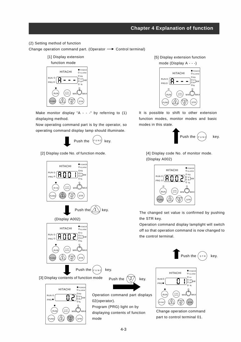
(2) Setting method of function
Change operation command part. (Operator Control terminal)
Chapter 4 Explanation of function
Make monitor display “A - - -“ by referring to (1)
displaying method.
Now operating command part is by the operator, so
operating command display lamp should illuminate.
[2] Display code No. of function mo
Oper
02(op
Prog
displ
mode
[3] Display contents of function mod
[1] Display extension
function mode
Push the 1
[5] Display extension function
mode (Display A - - -)
It is possible to shift to other extension
function modes, monitor modes and basic
modes in this state.
(Display A002)
F U N CPush the key.
POW ER
%
A
ALARM
RUN
PRG
VHz
kW
1 2
HITACHI
MIN MAX
STR
RUN
FUNC
STOP/RESET
%
A
ALARM
POW ER
RUN
PRG
VHz
kW
1 2
HITACHI
MIN MAX
STR
RUN
FUNC
STOP/RESET
ALARM
RUN
PRG
VHz
kW
1 2
POW ER HITACHI
MIN MAX
STR
RUN
FUNC
STOP/RESET
POW ER
ALARM
kW
%
A
RUN
PRG
V
Hz
1 2
HITACHI
MIN MAX
STR
RUN
FUNC
STOP/RESET
%
A
ALARM
POW ER
RUN
PRG
VHz
kW
1 2
HITACHI
MIN MAX
STR
RUN
FUNC
STOP/RESET
Push the F U N C
C
4-3
de.
ation command part displays
erator).
ram (PRG) light on by
aying contents of function
e
Change operation com
part to control termina
[4] Display code No. of mon
(Display A002)
key.
Push the
%
A
ALARM
POW ER
RUN
PRG
VHz
kW
1 2
HITACHI
MIN MAX
STR
RUN
FUNC
STOP/RESET
key.
%
A
ALARM
POW E
RUN
PRG
V
Hz
kW
1 2
HITACHI
MIN MA
STR
RUN
FUNC
STOP/RESET
itor mode.
S T R key.
Push the key.F U N
R
Push the key.2
The changed set value is confirmed by pushing
the STR key.
Operation command display lamplight will switch
off so that operation command is now changed to
the control terminal.
X
%
A
mand
l 01.

(3) Setting method of function code
Code No. of monitor modes, basic setting modes and extension function codes can be set easily.
Indicate the method to change code No.d001 of monitor mode to function code No. A029 simply.
Chapter 4 Explanation of function
Push the key together.1 2
[2] Change extension function mode
(Display A001)
”A” blinks.
The figure lighting is decided by
pushing STR key.
[3] Change third figure of
function code No.
Third figure “0” blinks.
Don’t change third figure and
push the STR key and confirm 0.
[4] Change second figure of
function code No.
Push the
1Push the key.
(2 times)
[5] Change first figure of
function code No.
First figure, “1” blinks.
”9” of first figure blinks.Finish setting A029
(Note) When you input code No.
there isn’t in the code list, “A” of left
end blinks again. Confirm code No.
and input it again.
Push the KeySTR
(Decide “9”)
Push the key. (2 times)
1
Push y.
Push the or key.
(2 times)
2
(9 times)
(Display A029)
Push the key.STR
RUN
PRG%A
ALARM
VHz
kW
H I T A C H I
FUNC
STOP/RESET
MAXMIN
STR
RUN
1 2
%A
ALARM
VHz
kW
H I T A C H I
FUNC
STOP/RESET
MAXMIN
STR
RUN
1 2
RUN
PRG
POW ER
%A
ALARM
VHz
kW
H I T A C H I
FUNC
STOP/RESET
MAXMIN
STR
RUN
1 2
RUN
PRG
POW ER
%A
ALARM
VHz
kW
H I T A C H I
FUNC
STOP/RESET
MAXMIN
STR
RUN
1 2
POW ER
RUN
PRG
%A
ALARM
VHz
kW
H I T A C H I
FUNC
STOP/RESET
MAXMIN
STR
RUN
1 2
RUN
PRG
POW ER
%A
ALARM
VHz
kW
H I T A C H I
FUNC
STOP/RESET
MAXMIN
STR
RUN
1 2
RUN
PRG
POW ER
%A
ALARM
VHz
kW
H I T A C H I
FUNC
STOP/RESET
MAXMIN
STR
RUN
1 2
POW ER
RUN
PRG
%A
ALARM
VHz
kW
H I T A C H I
FUNC
STOP/RESET
MAXMIN
STR
RUN
1 2
POW ER
RUN
PRG
ALARM
Hz
H I T A C H IPOW ER
4-4
Second figure, “0” blinks.
key.STR
%AV kW
FUNC
STOP/RESET
MAXMIN
STR
RUN
1 2
RUN
PRG
[1] Display code No. of monitor mode.
(Display d001)
”d” blinks.
(Confirm “0”)
Second figures, “2” blinks.
the keSTR
(Confirm “A”)
(Display A021)
[6] Finish setting
function code No.
1
POW ER
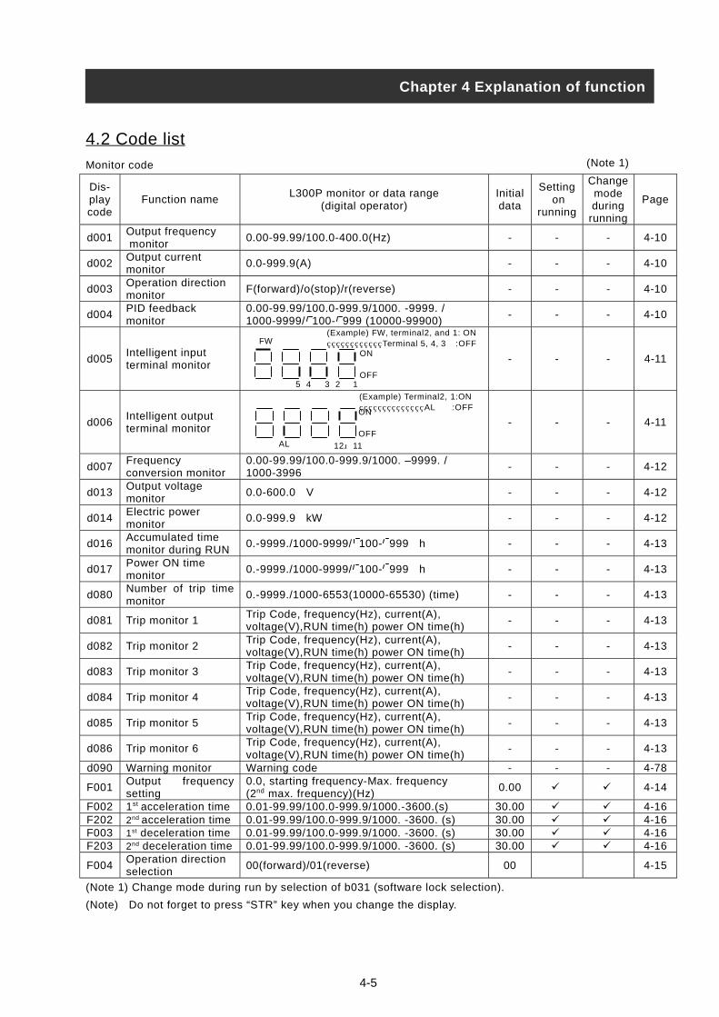
4-5
4.2 Code list
Monitor code
Dis-playcode
Function nameL300P monitor or data range
(digital operator)Initialdata
Setting on
running
Changemodeduring
running
Page
d001Output frequency monitor
0.00-99.99/100.0-400.0(Hz) - - - 4-10
d002Output currentmonitor
0.0-999.9(A) - - - 4-10
d003Operation directionmonitor
F(forward)/o(stop)/r(reverse) - - - 4-10
d004PID feedbackmonitor
0.00-99.99/100.0-999.9/1000. -9999. /1000-9999/ 100- 999 (10000-99900)
- - - 4-10
d005Intelligent inputterminal monitor
- - - 4-11
d006Intelligent outputterminal monitor
- - - 4-11
d007Frequencyconversion monitor
0.00-99.99/100.0-999.9/1000. –9999. /1000-3996
- - - 4-12
d013Output voltagemonitor
0.0-600.0 V - - - 4-12
d014Electric powermonitor
0.0-999.9 kW - - - 4-12
d016Accumulated timemonitor during RUN
0.-9999./1000-9999/ 100- 999 h - - - 4-13
d017Power ON timemonitor
0.-9999./1000-9999/ 100- 999 h - - - 4-13
d080Number of trip timemonitor
0.-9999./1000-6553(10000-65530) (time) - - - 4-13
d081 Trip monitor 1Trip Code, frequency(Hz), current(A),voltage(V),RUN time(h) power ON time(h)
- - - 4-13
d082 Trip monitor 2Trip Code, frequency(Hz), current(A),voltage(V),RUN time(h) power ON time(h)
- - - 4-13
d083 Trip monitor 3Trip Code, frequency(Hz), current(A),voltage(V),RUN time(h) power ON time(h)
- - - 4-13
d084 Trip monitor 4Trip Code, frequency(Hz), current(A),voltage(V),RUN time(h) power ON time(h)
- - - 4-13
d085 Trip monitor 5Trip Code, frequency(Hz), current(A),voltage(V),RUN time(h) power ON time(h)
- - - 4-13
d086 Trip monitor 6Trip Code, frequency(Hz), current(A),voltage(V),RUN time(h) power ON time(h)
- - - 4-13
d090 Warning monitor Warning code - - - 4-78
F001Output frequencysetting
0.0, starting frequency-Max. frequency(2nd max. frequency)(Hz)
0.00 4-14
F002 1st acceleration time 0.01-99.99/100.0-999.9/1000.-3600.(s) 30.00 4-16F202 2nd acceleration time 0.01-99.99/100.0-999.9/1000. -3600. (s) 30.00 4-16F003 1st deceleration time 0.01-99.99/100.0-999.9/1000. -3600. (s) 30.00 4-16F203 2nd deceleration time 0.01-99.99/100.0-999.9/1000. -3600. (s) 30.00 4-16
F004Operation directionselection
00(forward)/01(reverse) 00 4-15
(Note 1) Change mode during run by selection of b031 (software lock selection).
(Note) Do not forget to press “STR” key when you change the display.
Chapter 4 Explanation of function
(Note 1)
(Example) FW, terminal2, and 1: ON Terminal 5, 4, 3 :OFF
ON
OFF5 4 3 2 1
FW
(Example) Terminal2, 1:ON AL :OFFON
OFF
12 11AL
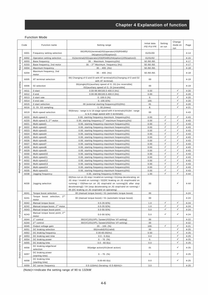
Function Mode
Code Function name Setting rangeInitial data
-FE/-FU/-FR
Setting
on run
Change
mode on
run
Page
A001 Frequency setting selection00(VR)/01(terminal)/02(operator)/03(RS485)/
04(option1)/05(option2)01/01/00 4-14
A002 Operation setting selection 01(terminal)/02(operator)/03(RS485)/04(option1)/05(option2) 01/01/02 4-15
A003 Base frequency 30. - Maximum. frequency(Hz) 50./60./60. 4-17
A203 Base frequency, 2nd motor 30. - 2nd Maximum. frequency (Hz) 50./60./60. 4-17
A004 Maximum frequency 30. - 400. (Hz) 50./60./60. 4-18
A204Maximum frequency, 2nd
motor30. - 400. (Hz) 50./60./60. 4-18
A005 AT terminal selection00( Changing of O and OI with AT terminal)/01(Changing of O and O2
with AT terminal)00 4-19
A006 02 selection00(single)/01(auxil iary speed of O, OI) [no reversible]
/02(auxil iary speed of O, OI [reversible]00 4-19
A011 0 start 0.00-99.99/100.0-400.0 (Hz) 0.00 4-20
A012 0 end 0.00-99.99/100.0-400.0 (Hz) 0.00 4-20
A013 0 start rate 0.-100.0 (%) 0. 4-20
A014 0 end rate 0.-100.0(%) 100. 4-20
A015 0 start selection 00 (external starting frequency)/01(0Hz) 01 4-20
A016 O, OI, O2 sampling 1.-30.(times) 8. 4-21
A019 Multi-speed selection00(binary : range is to 16 stage speed with 4 terminals)/01(bit : range
is to 6 stage speed with 5 terminals)00 4-43
A020 Multi-speed 0 0.00, starting frequency-maximum. frequency(Hz) 0.00 4-43
A220 Multi-speed 0, 2nd motor 0.00, starting frequency-2nd maximum frequency(Hz) 0.00 4-43
A021 Multi-speed1 0.00, starting frequency-maximum frequency(Hz) 0.00 4-43
A022 Multi-speed2 0.00, starting frequency-maximum frequency(Hz) 0.00 4-43
A023 Multi-speed3 0.00, starting frequency-maximum frequency(Hz) 0.00 4-43
A024 Multi-speed4 0.00, starting frequency-maximum frequency(Hz) 0.00 4-43
A025 Multi-speed5 0.00, starting frequency-maximum frequency(Hz) 0.00 4-43
A026 Multi-speed6 0.00, starting frequency-maximum frequency(Hz) 0.00 4-43
A027 Multi-speed7 0.00, starting frequency-maximum frequency(Hz) 0.00 4-43
A028 Multi-speed8 0.00, starting frequency-maximum frequency(Hz) 0.00 4-43
A029 Multi-speed9 0.00, starting frequency-maximum frequency(Hz) 0.00 4-43
A030 Multi-speed10 0.00, starting frequency-maximum frequency(Hz) 0.00 4-43
A031 Multi-speed11 0.00, starting frequency-maximum frequency(Hz) 0.00 4-43
A032 Multi-speed12 0.00, starting frequency-maximum frequency(Hz) 0.00 4-43
A033 Multi-speed13 0.00, starting frequency-maximum frequency(Hz) 0.00 4-43
A034 Multi-speed14 0.00, starting frequency-maximum frequency(Hz) 0.00 4-43
A035 Multi-speed15 0.00, starting frequency-maximum frequency(Hz) 0.00 4-43
A038 Jogging frequency 0.00, starting frequency-9.99(Hz) 1.00 4-44
A039 Jogging selection
00(free-run on JG stop / invalid on running) / 01(stop decelerating on
JG stop / invalid on running) / 02(DC braking on JG stop/invalid on
running) / 03(free-run on JG stop/valid on running[JG after stop
decelerating]) / 04 (stop decelerating on JG stop/valid on running) /
05 (DC braking on JG stop/valid on operating)
00 4-44
A041 Torque boost selection 00 (manual torque boost) / 01 (automatic torque boost) 00 4-24
A241Torque boost selection, 2nd
motor00 (manual torque boost) / 01 (automatic torque boost) 00 4-24
A042 Manual torque boost 0.0-20.0(%) 1.0 4-24
A242 Manual torque boost, 2nd motor 0.0-20.0(%) 1.0 4-24
A043 Manual torque boost point 0.0-50.0(%) 5.0 4-24
A243Manual torque boost point, 2nd
motor0.0-50.0(%) 5.0 4-24
A044 1st control 00/(VC)/01(VP1.7power)/02(free V/f setting) 00 4-22
A244 2nd control 00/(VC)/01(VP1.7power)/02(free V/f setting) 00 4-22
A045 Output voltage gain 20. - 100. (%) 100. 4-21
A051 DC braking selection 00(invalid)/01(valid) 00 4-25
A052 DC braking frequency 0.00-60.00(Hz) 0.50 4-25
A053 DC braking wait time 0.0 - 5.0(s) 0.0 4-25
A054 DC braking power 0. - 70. (%) 0. 4-25
A055 DC braking time 0.0 - 60.0(s) 0.0 4-25
A056DC braking edge/level
selection00(edge action)/01(level action) 01 4-25
A057DC braking power
(starting time)0. - 70. (%) 0. 4-25
A058DC braking time
(starting time)0.00-60.0(s) 0.0 4-25
A059 DC carrier frequency 0.5-12(kHz) Derating <0.5-8(kHz)> 3.0 4-25
Chapter 4 Explanation of function
Ba
se
se
ttin
gM
ult
ista
ge
sp
ee
d •
jo
gg
ing
fre
qu
en
cy
se
ttin
gV
/f c
ha
ract
eri
sti
cD
ire
ct
cu
rre
nt
bra
kin
gA
na
log
in
pu
t s
ett
ing
4-6
(Note)<>indicate the setting range of 90 to 132kW
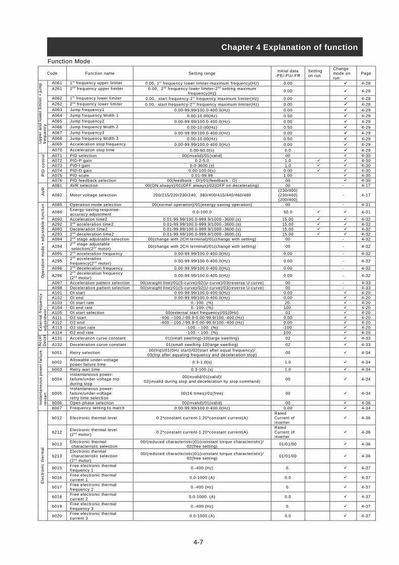
4-7
Function Mode
Code Function name Setting rangeInitial data
-FE/-FU/-FRSettingon run
Changemode onrun
Page
A061 1st frequency upper limiter 0.00, 1st frequency lower limiter-maximum frequency(Hz) 0.00 4-28A261 2nd frequency upper limiter 0.00, 2nd frequency lower limiter-2nd setting maximum
frequency(Hz)0.00 4-28
A062 1st frequency lower limiter 0.00, start frequency-1st frequency maximum limiter(Hz) 0.00 4-28A262 2nd frequency lower limiter 0.00, start frequency-2nd frequency maximum limiter(Hz) 0.00 4-28A063 Jump frequency1 0.00-99.99/100.0-400.0(Hz) 0.00 4-29A064 Jump frequency Width 1 0.00-10.00(Hz) 0.50 4-29A065 Jump frequency2 0.00-99.99/100.0-400.0(Hz) 0.00 4-29A066 Jump frequency Width 2 0.00-10.00(Hz) 0.50 4-29A067 Jump frequency3 0.00-99.99/100.0-400.0(Hz) 0.00 4-29A068 Jump frequency Width 3 0.00-10.00(Hz) 0.50 4-29A069 Acceleration stop frequency 0.00-99.99/100.0-400.0(Hz) 0.00 4-29A070 Acceleration stop time 0.00-60.0(s) 0.0 4-29A071 PID selection 00(invalid)/01(valid) 00 4-30A072 PID-P gain 0.2-5.0 1.0 4-30A073 PID-I gain 0.0-3600.(s) 1.0 4-30A074 PID-D gain 0.00-100.0(s) 0.00 4-30A075 PID scale 0.01-99.99 1.00 4-30A076 PID feedback selection 00(feedback : OI)/01(feedback : O) 00 4-30A081 AVR selection 00(ON always)/01(OFF always)/02(OFF on decelerating) 00 - 4-17
A082 Motor voltage selection 200/215/220/230/240, 380/400/415/440/460/480(230/400)(230/460)(200/400)
- 4-17
A085 Operation mode selection 00(normal operation)/01(energy-saving operation) 00 - 4-31
A086Energy-saving response-accuracy adjustment
0.0-100.0 50.0 4-31
A092 Acceleration time2 0.01-99.99/100.0-999.9/1000.-3600.(s) 15.00 4-32A292 2nd acceleration time2 0.01-99.99/100.0-999.9/1000.-3600.(s) 15.00 4-32A093 Deceleration time2 0.01-99.99/100.0-999.9/1000.-3600.(s) 15.00 4-32A293 2nd deceleration time2 0.01-99.99/100.0-999.9/1000.-3600.(s) 15.00 4-32A094 2nd stage adjustable selection 00(change with 2CH terminal)/01(change with setting) 00 - 4-32
A2942nd stage adjustable selection(2nd motor)
00(change with 2CH terminal)/01(change with setting) 00 - 4-32
A095 2nd acceleration frequency 0.00-99.99/100.0-400.0(Hz) 0.00 - 4-32
A2952nd accelerationfrequency(2nd motor)
0.00-99.99/100.0-400.0(Hz) 0.00 - 4-32
A096 2nd deceleration frequency 0.00-99.99/100.0-400.0(Hz) 0.00 - 4-32
A2962nd deceleration frequency(2nd motor)
0.00-99.99/100.0-400.0(Hz) 0.00 - 4-32
A097 Acceleration pattern selection 00(straight line)/01(S-curve)/02(U-curve)/03(reverse U-curve) 00 - 4-33A098 Deceleration pattern selection 00(straight line)/01(S-curve)/02(U-curve)/03(reverse U-curve) 00 - 4-33A101 OI start 0.00-99.99/100.0-400.0(Hz) 0.00 4-20A102 OI end 0.00-99.99/100.0-400.0(Hz) 0.00 4-20A103 OI start rate 0.-100. (%) 20. 4-20A104 OI end rate 0.-100. (%) 100. 4-20A105 OI start selection 00(external start frequency)/01(0Hz) 01 4-20A111 O2 start -400.--100./-99.9-0.00-99.9/100.-400.(Hz) 0.00 4-20A112 O2 end -400.--100./-99.9-0.00-99.9/100.-400.(Hz) 0.00 4-20A113 O2 start rate -100. - 100. (%) -100. 4-20A114 O2 end rate -100. - 100. (%) 100. 4-20
A131 Acceleration curve constant 01(small swelling)-10(large swelling) 02 4-33
A132 Deceleration curve constant 01(small swelling-10(large swelling) 02 4-33
b001 Retry selection00(trip)/01(0Hz start)/02(start after equal frequency)/
03(trip after equaling frequency and deceleration stop)00 4-34
b002Allowable under-voltagepower failure time
0.3-1.0(s) 1.0 4-34
b003 Retry wait time 0.3-100.(s) 1.0 4-34
b004Instantaneous power-failure/under-voltage tripduring stop
00(invalid/01(valid)/02(invalid during stop and deceleration by stop command)
00 4-34
b005Instantaneous power-failure/under-voltageretry time selection
00(16 times)/01(free) 00 4-34
b006 Open-phase selection 00(invalid)/01(valid) 00 4-36b007 Frequency setting to match 0.00-99.99/100.0-400.0(Hz) 0.00 4-34
b012 Electronic thermal level 0.2*constant current-1.20*constant current(A)RatedCurrent ofinverter
4-36
b212Electronic thermal level(2nd motor)
0.2*constant current-1.20*constant current(A)RatedCurrent ofinverter
4-36
b013Electronic thermal characteristic selection
00/(reduced characteristic)01(constant torque characteristic)/02(free setting)
01/01/00 4-36
b213Electronic thermal characteristic selection(2nd motor)
00/(reduced characteristic)01(constant torque characteristic)/02(free setting)
01/01/00 4-36
b015Free electronic thermalfrequency 1
0.-400.(Hz) 0. 4-37
b016Free electronic thermalcurrent 1
0.0-1000.(A) 0.0 4-37
b017Free electronic thermalfrequency 2
0.-400.(Hz) 0. 4-37
b018Free electronic thermalcurrent 2
0.0-1000. (A) 0.0 4-37
b019Free electronic thermalfrequency 3
0.-400.(Hz) 0. 4-37
b020Free electronic thermalcurrent 3
0.0-1000.(A) 0.0 4-37
Chapter 4 Explanation of functionU
pp
er
an
d l
ow
er
lim
ite
r •
jum
pfr
eq
ue
nc
yP
ID c
on
tro
lE
xte
rna
l fr
eq
ue
nc
ya
dju
stm
en
tA
VR
Op
era
tio
n m
od
e •
ad
jus
tab
le f
un
cti
on
Ac
ce
lD
ece
lIn
sta
nta
ne
ou
s p
ow
er
fail
ure
res
tart
Ele
ctr
on
ic t
he
rma
l

4-8
Function Mode
Code Function name Setting rangeInitial data
-FE/-FU/-FRSettingon run
Changemode onrun
Page
b021Overload restrictionselection
00(invalid)/01(enabled on acceleration / constant speed)/02(enabledon constant speed)
01 4-38
b022 Overload restriction level 0.50* rated current-1.50* rated current(A)
Ratedcurrent ofinverterx 1.20
4-38
b023Overload restriction limitconstant
0.10-30.00(s) 1.00 4-38
b024Overload restriction 2selection
00(invalid)/01(valid on acceleration / constant speed)/02(valid onconstant speed)
01 4-38
b025 Overload restriction level 2 0.50*rated current-1.50*rated current(A)
Ratedcurrent ofinverterx1.20
4-38
b026Overload restrictionconstant 2
0.10-30.00(s) 1.00 4-38
b031Software lock modeselection
00(impossible to change the data except this item when SFT terminalis ON)/01(impossible to change the data except setting frequencyitem when SFT terminal is ON)/02(impossible to change the dataexcept this item)/03(impossible to change the data except settingfrequency item)/10(possible to change data on operating)
01 4-45
b100 Free V/f frequency 1 0.- Free V/f frequency2(Hz) 0. 4-23b101 Free V/f voltage 1 0.-800.0(V) 0.0 4-23b102 Free V/f frequency 2 0.- Free V/f frequency3(Hz) 0. 4-23b103 Free V/f voltage 2 0.-800.0(V) 0.0 4-23b104 Free V/f frequency 3 0.- Free V/f frequency4(Hz) 0. 4-23b105 Free V/f voltage 3 0.-800.0(V) 0.0 4-23b106 Free V/f frequency 4 0.- Free V/f frequency5(Hz) 0. 4-23b107 Free V/f voltage 4 0.-800.0(V) 0.0 4-23b108 Free V/f frequency 5 0.- Free V/f frequency6(Hz) 0. 4-23b109 Free V/f voltage 5 0.-800.0(V) 0.0 4-23b110 Free V/f frequency 6 0.- Free V/f frequency7(Hz) 0. 4-23b111 Free V/f voltage 6 0.-800.0(V) 0.0 4-23b112 Free V/f frequency 7 0.-400.(Hz) 0. 4-23b113 Free V/f voltage 7 0.-800.0(V) 0.0 4-23
C001 Intelligent input 1 setting 18 4-42
C002 Intelligent input 2 setting 16 4-42
C003 Intelligent input 3 setting 03/13/03 4-42
C004 Intelligent input 4 setting 02 4-42
C005 Intelligent input 5 setting
01/(RV:Reverse is valid)/02(CF1:Multi-speed1)/ 03(CF2:Multi-speed2)/04(CF3:Multi-speed3)/ 05(CF4:Multi-speed4)/ 06(JG:Jogging)/07(DB:External DC braking)/08(SET:2nd control)/09(2CH:two-stage adjustable speed)/11(FRS:Free-run)/12(EXT:External trip)/13(USP:Unattended start protection)/14(CS:commercial change)/15(SFT:software lock)/16(AT:Analog input voltage/current select)/18(RS:Reset inverter)/20(STA:3wire run)/ 21(STP:3wire keep)/22(F/R:3wire forward/reverse)/23(PID:PID selection valid/invalid)/24(PIDC:PID integrating reset)/27(UP:Remote control UP function)/28(DWN:Remote control DOWN function)/29(UDC:Remote control data clear)/31(OPE:Force operate ope)/32(SF1:Multi-speed bit1)/33(SF2:Multi-speed bit2)/34(SF3:Multi-speed bit3)/35(SF4:Multi-speed bit4)/36(SF5:Multi speed bit5)/37(SF6:Multi-speed bit6)/38(SF7:Multi-speed bit7)/39(OLR:Overload restriction change)/no(NO:No assign)
01 4-42
C011Intelligent input1 a/b(NO/NC) selection
00(NO)/01(NC) 00 4-42
C012Intelligent input2 a/b(NO/NC) selection
00(NO)/01(NC) 00 4-42
C013Intelligent input3 a/b(NO/NC) selection
00(NO)/01(NC) 00/01/00 4-42
C014Intelligent input4 a/b(NO/NC) selection
00(NO)/01(NC) 00 4-42
C015Intelligent input5 a/b(NO/NC) selection
00(NO)/01(NC) 00 4-42
C019Input FW a/b (NO/NC)Selection
00(NO)/01(NC) 00 4-42
C021 Intelligent output 11 setting 01 4-51
C022 Intelligent output 12 setting 00 4-51
C026 Alarm relay output
00(RUN:running)/01(FA1:Frequency arrivaltype1 signal)/02(FA2:frequency arrival type2 signal)/03(OL:Overload advancenotice signal)/04(OD:Output deviation for PID control)/05(AL:Alarmsignal)/06(FA3:Only setting frequency)/08(IP:On instantaneous stop/09(UV:Under voltage)/11(RNT:RUN time over)/12(ONT:ON timeover)/13(THM:thermal caution)
05 4-51
C027 FM selection00(Output frequency)/01(Output current) /03(Digital output frequency)/04(Output voltage)/05(Input electric power)/06(thermal load rate)/07(LAD frequency)
00 4-56
C028 AM selection00(Output frequency)/01(Output current)/04(Output voltage)/05(Input electric power)/06(thermal load rate)/07(LAD frequency)
00 4-57
C029 AMI selection00(Output frequency)/01(Output current)/04(Output voltage)/05(Input electric power)/06(Thermal load rate)/07(LAD frequency)
00 4-57
C031 Intelligent output 11 a/b 00(NO)/01(NC) 00 4-52C032 Intelligent output 12 a/b 00(NO)/01(NC) 00 4-52C036 Alarm relay output a/b 00(NO)/01(NC) 01 4-52
C040Overload advance noticesignal output mode
00(On accel. And decel, constant speed)/01(Only constant speed) 01 4-39
C041Overload advance noticelevel
0.0-2.0*rated current(A)Inverter
rated current 4-38
C042Frequency arrival settingfor acceleration.
0.00-99.99/100.0-400.0(Hz) 0.00 4-53
C043Arrival frequency setting fordeceleration.
0.00-99.99/100.0-400.0(Hz) 0.00 4-53
C044 PID deviation setting level 0.0-100.0(%) 3.0 4-31
Chapter 4 Explanation of functionO
ve
rlo
ad
lim
itL
oc
kF
ree
V/f
se
ttin
gIn
tell
ige
nt
inp
ut
term
ina
l s
ett
ing
Inp
ut
term
ina
l s
ett
ing
inte
llig
en
tO
utp
ut
term
ina
l s
tate
se
ttin
gO
utp
ut
lev
el
se
ttin
gIn
tell
ige
nt
ou
tpu
t te
rmin
al
se
ttin
g

Function Mode
Code Function name Setting rangeInitial data
-FE/-FU/-FRSetting onrun
Changemode onrun
Page
C070 Data command 02(operator)/03(RS485)/04(option1)/05(option2) 02 4-61
C071Communicatingtransmission speed
02(loop-back test)/03(2400bps)/04(4800bps)/05(9600bps)/06(19200bps)
04 4-61
C072 Communication code 1. -32. 1. 4-61C073 Communication bit 7(7bit)/8(8bit) 7 4-61C074 Communication parity 00(no parity name)/01(even parity)/02(odd parity) 00 4-61C075 Communication stop bit 1(bit)/2(bit) 1 4-61C078 Communication waiting time 0.-1000.(ms) 0. 4-61C081 O adjustment 0.-9999./1000-6553(10000-65530) Set on forwarding -C082 OI adjustment 0.-9999./1000-6553(10000-65530) Set on forwarding -C083 O2 adjustment 0.-9999./1000-6553(10000-65530) Set on forwarding -C085 Thermistor adjustment 0.0 - 1000. 105.0 4-57C086 AM offset adjustment 0.0 - 10.0(V) 0.0 4-57C087 AMI adjustment 0. - 255. 80 4-57C088 AMI offset adjustment 0. - 20.0(mA) Set on forwarding 4-57b034 RUN time/Power ON time level 0.-9999./1000-6553(10000-65530)hr 0. 4-55b035 Operation direction restrict 00(Reverse is valid)/01(Only forward)/02(Only reverse) 00 4-14
b036 Start reduced voltage00(Start reduced voltage time small)-06(Start reduced voltage time large)
06 4-40
b037 Display selection00(all display)/01(each function display)/
02(User setting / main setting)00 4-59
b080 AM adjustment 0. - 255. 180 4-57b081 FM adjustment 0. - 255. 60 4-56b082 Start frequency adjustment 0.10-9.99(Hz) 0.50 4-40b083 Carrier frequency setting 0.5-12.0(kHz) Derating enable<0.5 - 8> (Note 1) 3.0 4-18
b084 Initialize mode00(Trip history clear)/01(Data initialization)/
02(Trip history clear + data initialization)00 4-58
b085 Country code for initialization 00(Interior)/01(EC)/02(USA) 01/02/00 4-58
b086Frequency scalarconversion factor
0.1-99.9 1.0 4-12
b087 STOP key enable 00(valid)/01(invalid) 00 4-15
b088Resume on FRScancellation mode
00(0Hz start)/01(Start f-equaling) 00 4-46
b090 BRD usage ratio 0.0-100.0(%) 0.0 4-41b091 Stop mode selection 00(deceleration stop)/01(Free-run stop) 00 4-15
b092 Cooling fan control00(Always ON)/01(ON during run, After power ON, then for 5 minutes
on stop is implied.)00 4-41
b095 BRD selection00(invalid)/01(valid<invalid during stop>)/
02(valid<valid during stop>)00 4-41
b096 BRD ON level 330-380/660-760(V) 360/720 4-41
b098 Thermistor selection00(invalid)/01(Positive temperature coefficient enable)/
02 (NTC enable)00 4-57
b099 Thermistor error level 0. – 9999. (ohm) 3000. 4-57C061 Thermal warning level 0. – 100. (%) 80 4-36C091 Debug mode selection 00(No display)/01(Display) 00 -C101 UP/DWN selection 00(No frequency data)/01(Keep frequency data) 00 4-49
C102 Reset selection00(Trip cancel during ON)/01(Trip cancel during OFF)/
02(Valid only during trip<Cancel during ON>)00 4-48
C103Reset f frequency matchingselection
00(0Hz start)/01(Start f-equaling) 00 4-48
C121 O zero adjustment 0.-9999./1000-6553(10000-65530) Set on forwarding -C122 OI zero adjustment 0.-9999./1000-6553(10000-65530) Set on forwarding -C123 O2 zero adjustment 0.-9999./1000-6553(10000-65530) Set on forwarding -H003 1st allowable motor selection 0.20-90.0(kW) <0.2-160 kW> (Note 1) Set on forwarding 4-60H203 2nd allowable motor selection 0.20-90.0(kW) <0.2-160 kW> (Note 1) Set on forwarding 4-60H004 1st motor pole selection 2/4/6/8(pole) 4 4-60H204 2nd motor pole selection 2/4/6/8(pole) 4 4-60H006 1st stabilized factor 0. - 255. 100. 4-60H206 2nd stabilized factor 0. - 255. 100. 4-60
P001Option1 operation selectionon error
00(TRP)/01(RUN) 00 4-60
P002Option2 operation selectionon error
00(TRP)/01(RUN) 00 4-60
P031Digital input option inputmode selection(Acc/Dec)
00(operation)/01(option1)/02(option2) 00 -
<P044>DeviceNet running order ofmonitoring timer setting
0.00-99.99s 1.00 (Note 2)
<P045>Setting in action of abnormalcommunication
00(trip)/01(trip after deceleration stop)/02(invalid)/03(free-run)/04(deceleration stop)
01 (Note 2)
<P046>Output assemble instanceNumber setting
20, 21, 100 21 (Note 2)
<P047>Input assemble instanceNumber setting
70, 71, 101 71 (Note 2)
<P048>Detect of idol mode formotion setting
00(trip)/01(trip after deceleration stop)/02(invalid)/03(free-run)/04(deceleration stop)
01 (Note 2)
<P049> Pole setting of rotation speed 0-38(even only) 0 (Note 2)U001 User1 selection no/d001-P031 no 4-59U002 User2 selection no/d001-P031 no 4-59U003 User3 selection no/d001-P031 no 4-59U004 User4 selection no/d001-P031 no 4-59U005 User5 selection no/d001-P031 no 4-59U006 User6 selection no/d001-P031 no 4-59U007 User7 selection no/d001-P031 no 4-59U008 User8 selection no/d001-P031 no 4-59U009 User9 selection no/d001-P031 no 4-59U010 User10 selection no/d001-P031 no 4-59U011 User11 selection no/d001-P031 no 4-59U012 User12 selection no/d001-P031 no 4-59
An
alo
gm
ete
r s
ett
ing
Th
e o
the
rsC
om
mu
nic
ati
on
fun
cti
on
Chapter 4 Explanation of function
(Note 1)<>indicate the setting range of 90 to 132kW
(Note 2)<>indicate the setting range of 11 to 75kW
4-9

4-10
4.3 Explanation of function
4.3.1 Monitor modeOutput frequency monitor
Indication code d001 displays the frequency the inveter outputs.
The data is displayed as follows.
When d001 is displayed, the monitor lamp “Hz” is illuminated.
(Display)
0.00 - 99.99 : Display is in 0.01Hz unit.
100.0 - 400.0 : Display is in 0.1Hz unit.
(Note) When with digital operator, setting frequency output frequency is
adjustable by changing this mode.
Output current monitorIndication code d002 displays the output current value.
The data is displayed as follows.
In case of displaying d002, the monitor lamp “A” is illuminated.
(Display)
0.0 - 999.9 : Display is in 0.1A unit.
Operation direction monitor Indication code d003 displays the direction that the Inverter output is
rotating. Forward, reverse or stop.
On operating the inverter (in case of forward or reverse), the RUN lamp
will illuminate.
(Display)
F : Forward
o : Stop
r : Reverse
PID feedback monitor When you select PID function (01) in A071, the inverter displays the feedback
value changed by A075 (PID scale).
“ Display of monitor part ” = “ Feedback quantity “ x “ PID scale “
(Frequency command value) (A075)
(Setting)
A071 : 0.1(PID is effective)
A075 : 0.01-99.99(Display is 0.01-99.99(Set with the 0.01 unit)
(Display)
0.00 - 99.99 : Display is in 0.01 unit.
100.0 - 999.9 : Display is in 0.1 unit.
1000 - 9999 : Display is in 1 unit.
100 - 999 : Display is in 100 unit.
Chapter 4 Explanation of function
d001: Output frequency
monitor
Relation code
d002: Output current
monitor
Relation code
d003: Operation direction
monitor
Relation code
d004: PID feedback monitor
A071: PID selection
A075: PID scale
Relation code
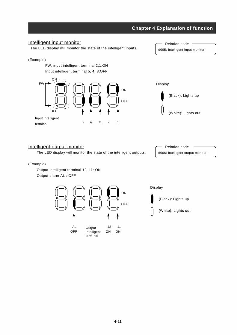
4-11
Intelligent input monitor The LED display will monitor the state of the intelligent inputs.
(Example)
FW; input intelligent terminal 2,1:ON
Input intelligent terminal 5, 4, 3:OFF
Intelligent output monitorThe LED display will monitor the state of the intelligent outputs.
(Example)
Output intelligent terminal 12, 11: ON
Output alarm AL : OFF
Chapter 4 Explanation of function
d00
Disp
Input intelligent
terminal
d00
2 1Outputintelligentterminal
5 4 3 2 1
ON
OFF
FWON
OFF
Relation code
5: Intelligent input monitor
lay
(Black): Lights up
(White): Lights out
Relation code
6: Intelligent output monitor
OFF
AL
OFF
ON
1
ON
1
ON
Display
(Black): Lights up
(White): Lights out

4-12
Frequency conversion monitor This inverter displays the value changed by the Inverter output frequency
and the value set in b086 on the monitor part.
“Monitor part of display” = “ output frequency(d001)” x “ output frequency
factor(b086)”
(Display) Display of d007
0.00 - 99.99: Display is in 0.01 unit.
100.0 - 999.9: Display is in 0.1 unit.
100. - 9999.: Display is in 1 unit.
1000 - 3996 :Display is in 10 unit.
(Range of setting) The setting range of b086
0.1 - 99.9 :Set it with the 0.1 unit.
(Example)Output frequency (d001):50.00Hz
When the frequency conversion factor (b086) is 1.1,
the frequency conversion monitor (d007) displays “55.00” as “50 x 1.1 = 55.00”.
(Note)Output frequency of FM terminal becomes same as d007 at the time of setting up
the digital output frequency to the FM terminal.
Output voltage monitor This inverter displays the output voltage of the inverter converted into the
alternating Voltage.
The monitor lamp “V” should illuminate while the contents of d013 are displayed.
(Display)
0.0 – 600.0 :Display is in 0.1V unit.
Input electric power monitorDisplay input electric power from inverter.
The monitor lamp “kW” (“V” and “A”) should illuminate while the contents of d014
is displayed.
(Display)
0.0 – 999.9 :Display is in 0.1kW unit.
Chapter 4 Explanation of function
d007: Frequency conversion
monitor
b086: Frequency conversion
factor
Relation code
d013: Output voltage
monitor
Relation code
d014: Input electric
power monitor
Relation code

4-13
Accumulated time monitor on RUN The operation time of inverter is accumulated and the value is displayed.
(Display)
0. - 9999. : Display is in 1 hour units.
1000 - 9999 : Display is in 10 hour units.
100 - 999 : Display is in 1000 hour units.
Power ON time monitor This accumulates the time running to the inverter and displays the value.
(Display)
0. - 9999. : Display is in 1 hour units.
1000 - 9999 : Display is in 10 hour units.
100 - 999 : Display is in 1000 hour units.
Trip time monitor This displays the number of inverter trips.
(Display)
0. - 9999. : Display is in 1 times unit.
1000 - 6553 : Display is in 10 times unit.
Trip monitor 1-6 This displays the details for the last six protective trips.
The trip monitor 1 displayed the details of the last trip.
(Display contents)
[1] Trip Code (Display anything from E01 to E79.)(Note 1)
[2] Output frequency on tripping (Hz)
[3] Output current on tripping (A)
[4] The direct voltage (between P and N) on tripping (V)
[5] The accumulated time inverter was operating until tripping (h)
[6] The accumulated time inverter was run until tripping (h)
(Note 1) Please refer to the pages 4.4 Protection function list (2) Trip monitor display
Chapter 4 Explanation of function
d016: Accumulated time
monitor on RUN
Relation code
d080
d081
d082
d083
d084
d085
d086
The methods of trip monitor
(Note 2) In case of no tripping is displayed.
(1) Trip factor(Note 2)
(2) Trip frequency (3) Trip current(4)Trip voltage (P-N)
(5) Ac機能FUNC
機能FUNC
Relation code
Relation code
: Trip time monitor
Relation code
d017: Power ON time
monitor
.
: Trip monitor 1
: Trip monitor 2
: Trip monitor 3
: Trip monitor 4
: Trip monitor 5
: Trip monitor 6
cumulated (6) Power ON
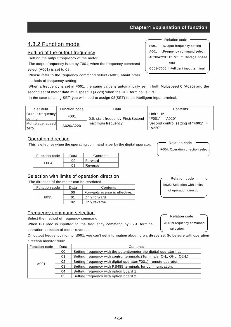
4-14
4.3.2 Function mode
Setting of the output frequency Setting the output frequency of the motor.
The output frequency is set by F001, when the frequency command
select (A001) is set to 02.
Please refer to the frequency command select (A001) about other
methods of frequency setting.
When a frequency is set in F001, the same value is automatically set in both Multispeed 0 (A020) and the
second set of motor data multispeed 0 (A220) when the SET terminal is ON.
In the case of using SET, you will need to assign 08(SET) to an intelligent input terminal.
Set item Function code Data Contents
Output frequencysetting
F001
Multistage speedzero
A020/A220
0.0, start frequency-First/Secondmaximum frequency
Unit : Hz“F001” = “A020”Second control setting of “F001” =“A220”
Operation direction This is effective when the operating command is set by the digital operator.
Function code Data Contents
00 ForwardF004
01 Reverse
Selection with limits of operation direction The direction of the motor can be restricted.
Function code Data Contents
00 Forward/reverse is effective.
01 Only forwardb035
02 Only reverse
Frequency command selectionSelect the method of frequency command.
When 0-10Vdc is inputted to the frequency command by 02-L terminal,
operation direction of motor reverses.
On output frequency monitor d001, you can’t get information about forward/reverse. So be sure with operation
direction monitor d002.
Function code Data Contents
00 Setting frequency with the potentiometer the digital operator has.
01 Setting frequency with control terminals (Terminals: O-L, OI-L, O2-L)
02 Setting frequency with digital operator(F001), remote operator.
03 Setting frequency with RS485 terminals for communication.
04 Setting frequency with option board 1.
A001
05 Setting frequency with option board 2.
Chapter4 Explanation of function
F004: Operation direction select
Relation code
F001 :Output frequency setting
A001 :Frequency command select
A020/A220: 1st /2nd multistage speed
zero
C001-C005: Intelligent input terminal
Relation code
b035: Selection with limits
of operation direction
Relation code
A001:Frequency command
selection
Relation code

4-15
Operation command selection Select the control of RUN/STOP commands.
Operation command from the control terminals (Terminal)
tart/Stop by ON/OFF of control terminals.
Forward : FW-CM1 terminal
Reverse : RV-CM1 terminal
Put 01(RV) to an intelligent Input terminal.
When using the FW terminal, it is possible to change the contact from NO to NCby settin a or b (respectively)
in C019.When operating from the digital operator, set operation direction in F004.Or operate Start/Stop with
RUN key/STOP key on the digital operator.It becomes stop command when proper forword command and
reverse command are inputted at the same time.
Set item Function code Data Contents
01 Start/Stop with control terminals(Terminal).(FW, RV)
02 Start/Stop with digital operator, remote operator.
03 Start/Stop with RS485 terminals for communications.
04 Start/Stop with option board 1.
Operation
command
selection
A002
05 Start/Stop with option board 2.
00 a contact (NO)Input FW a/b
(NO/NC)
selection
C019
C011-C015 01 b contact (NC)
Selection on stop When stop is commanded from the digital operator or the control
terminals (Terminal), select the stop after slowing-down according to
slowing-down time or the free run stop.
When the second cycle is started while in free run stop, the inverter
follows the free-run stop selection b088 and restarts.
(Refer to the item of free-run stop.)
Set itemFunction
codeData Contents
00 Normal stop (Decelerated stop)Selection on Stop b091
01 Free-run stop
00 0Hz startSelection of free-run stop b088
01 Start frequency matching
Frequency setting to match b007 0.00-400.0 Unit : Hz
Waiting time for retrying b003 0.3-100. Unit : second
Selection of Stop key Even though the control terminals are selected for the operation command,
you can still set whether the stop key of operator (digital operator etc) is
effective or not. Trip reset functions by the stop key follows this establishment,
too.
Function code Data Contents
00 The stop key is effective.b087
01 The stop key is ineffective.
b087: Selection of stop key
Relation code
b091 :Selection on stop
F003/F203: 1st /2nd deceleration time
b003 :Waiting time for retrying
b007 :Frequency setting to match
b088 :Select for free-run stop
Relation code
A002 :Operation command selection
C001-C005: Input intelligent terminal
C019 :Inputting FW a/b (NO/NC) selection
F004 :Operation direction select
Relation code
Chapter4 Explanation of function

Adjustable time The acceleration and deceleration time can be set.
Set a long time to accelerate or decelerate slowly or set a short
time to accelerate or decelerate quickly.
The time setting is the time it takes to accelerate from zero to the
maximum frequency and to decelerate from the maximum
frequency to zero.
Switching of the 1st/2nd/3ndacceleration time and the 1st/2nd/3nddeceleration time can be controlled with
intelliginet input terminal assigned to 08 (SET)/17(SET3).
Set item Function code Limit of setting Contents
Acceleration
timeF002/F202 0.01-3600.
Unit : second
Setting acceleration time from zero to maximum
frequency.
Deceleration
timeF003/F203 0.01-3600.
Unit : second
Setting deceleration time from maximum
frequency to zero.
However short you set the adjustable time, the adjustable time of the actual motor can’t be shorter than the
shortest adjustable time determined by the inertial Effect J of the mechanical system and motor torque.
If you set the time shorter than the shortest adjustable time, a protection trip of OC or OV may occur.
Acceleration time ts
ts =
Deceleration time tB
tB=
Chapter4 Explanation of function
F002/F202: 1st /2nd acceleration time
F003/F203: 1st /2nd deceleration time
A004/A204: 1st /2nd maximum frequency
Relation code
Output frequency setting
Output frequency
Maximum
frequency
A004/A204
Actual
acceleration
time
F002/F202
Actual
deceleration
time
F003/F203
(JL + JM) x NM
9.55 x (TS - TL)
(JL + JM) x NM
9.55 x (TB+TL)
JL: J of the load converted into motor shaft (kg•m2 )
JM: J of the motor (kg•m2 )
NM: Motor revolving (r/min)
TS: The maximum motor acceleration torque on inverter driving (N•m)
TB: The maximum motor deceleration torque on inverter driving (N•m)
TL: Needed transit torque (N•m)
4-16
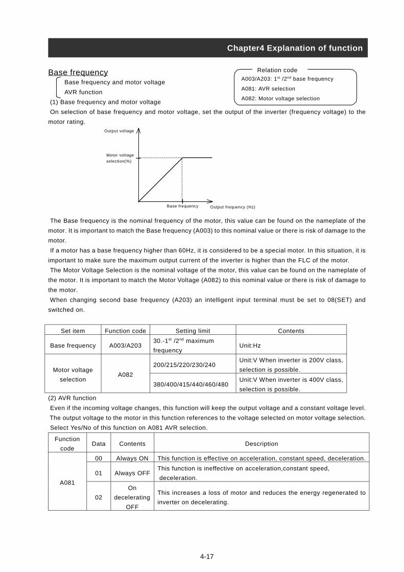
4-17
Base frequencyBase frequency and motor voltage
AVR function
(1) Base frequency and motor voltage
On selection of base frequency and motor voltage, set the output of the inverter (frequency voltage) to the
motor rating.
The Base frequency is the nominal frequency of the motor, this value can be found on the nameplate of the
motor. It is important to match the Base frequency (A003) to this nominal value or there is risk of damage to the
motor.
If a motor has a base frequency higher than 60Hz, it is considered to be a special motor. In this situation, it is
important to make sure the maximum output current of the inverter is higher than the FLC of the motor.
The Motor Voltage Selection is the nominal voltage of the motor, this value can be found on the nameplate of
the motor. It is important to match the Motor Voltage (A082) to this nominal value or there is risk of damage to
the motor.
When changing second base frequency (A203) an intelligent input terminal must be set to 08(SET) and
switched on.
Set item Function code Setting limit Contents
Base frequency A003/A20330.-1st /2nd maximum
frequencyUnit:Hz
200/215/220/230/240Unit:V When inverter is 200V class,
selection is possible.Motor voltage
selectionA082
380/400/415/440/460/480Unit:V When inverter is 400V class,
selection is possible.
(2) AVR function
Even if the incoming voltage changes, this function will keep the output voltage and a constant voltage level.
The output voltage to the motor in this function references to the voltage selected on motor voltage selection.
Select Yes/No of this function on A081 AVR selection.
Function
codeData Contents Description
00 Always ON This function is effective on acceleration, constant speed, deceleration.
01 Always OFFThis function is ineffective on acceleration,constant speed,
deceleration.A081
02
On
decelerating
OFF
This increases a loss of motor and reduces the energy regenerated to
inverter on decelerating.
Chapter4 Explanation of function
A003/A203: 1st /2nd base frequency
A081: AVR selection
A082: Motor voltage selection
Relation code
Output voltage
Motor voltage
selection(%)
Output frequency (Hz)Base frequency

4-18
CAUTION
Maximum frequency Set the maximum frequency value of the inverter.
This set value is the maximum frequncey that the inverter will achieve when
It receives top speed reference from the control terminalsor the digital operator.
To the change the 1st/2nd maximum frequency, set an intelligent
input terminal to 08(SET) and switch the input ON.
The Inverter output voltage from the base frequencey to the
maximum frequency is the same level as the voltage
selected on the motor voltage selection.
Function code Limit of setting Contents
A004/A204 30.-400. Unit : Hz
Carrier frequency The carrier frequency of the PWM wave-form output from the inverter is adjustable
by changing b083.
If the carrier frequency is set higher, the audible noise from motor will be reduced
but the RFI noise and the leakage current may be increased.
This function may help to avoid the resonant frequency of
the motor or the mechanical system.
(Note 1) The maximum value of the carrier frequency in order to achieve full output current is different
depending on the capacity. When raising the carrier frequency, the rated output current will be reduced.
Voltageclass 200V class 400V class
Contents(kW)
Maximum carrierfrequency
(kHz)
Derating on carrierfrequency = 12kHz
Maximum carrierfrequency
(kHz)
Derating on carrierfrequency = 12kHz(8kHz 90kW to 132kW)
11 12 100% 12 100%15 12 100% 12 100%
18.5 10 90% 12 100%22 4 80% 12 100%30 3 70% 8 90%37 8 80% 10 80%45 10 95% 10 95%55 6 75% 10 95%75 3 70% 5 60%90 – – 6 95%110 – – 6 85%132 – – 6 85%
: Be sure to keep the above-mentioned table. Otherwise, there is a danger of inverter unit breakage. When using at 50ºC of ambient air temperature, the rated output current will be
reduced as below (Fig.reference).
Chapter4 Explanation of function
Output voltage
Maximum frequencyBasic frequency
Motor Voltageselection(100%)
A004/A204: 1st /2nd maximum
frequency
Relation code
b083: Carrier frequency
Relation code
0.5-12.0(Note 1)
Unit: kHz (90 to 132kW)
Function code Limit of setting Contents
b083Unit: kHz (11 to 75kW)
0.5-8.0(Note 1)
0.5 2 4 6 8 10 12
100%
95%
90%
85%
80%
75%
70%
65%
55%
60% % o
f D
rive
Ra
ted
Am
ps
Carrier frequency (kHz)
450L,450H,550H
370L 110L,150L110 to 220H
300H
550L
750H
185L220L
300L,750L
370H
900H
1100H,1320H
185L,185H,220H
100%
95%
90%
85%
80%
75%
70%
65%
220L
150L,150H
450H
300H
370L
60%
55%
% o
f D
riv
e R
ate
d A
mp
s
110L,110H
750L,750H
550H
550L 370H
Carrier Frequency (kHz)
300L
900H
1100,1320H
Fig.reference: at 50ºC of ambient air temperature
450L
0.5 2 4 6 8 10 12
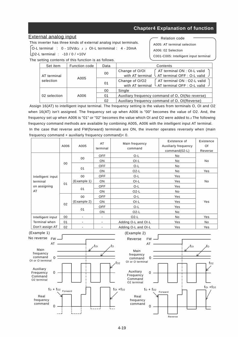
4-19
External analog input This inverter has three kinds of external analog input terminals.
O-L terminal : 0 - 10Vdc OI-L termminal : 4 - 20mA
O2-L terminal : -10 / 0 / +10V
The setting contents of this function is as follows.
Set item Function code Data Contents
00Change of O/OI AT terminal ON : OI-L valid with AT terminal AT terminal OFF : O-L validAT terminal
selectionA005
01Change of O/O2 AT terminal ON : O2-L valid with AT terminal AT terminal OFF : O-L valid
00 Single
01 Auxiliary frequency command of O, OI(No reverse)02 selection A006
02 Auxiliary frequency command of O, OI(Reverse)
Assign 16(AT) to intelligent input terminal. The frequency setting is the values from terminals O, OI and O2
when 16(AT) isn’t assigned. The frequency set up when A006 is "00" becomes the value of O2. And, the
frequency set up when A006 is "01" or "02" becomes the value which OI and O2 were added to. The following
frequency command methods are available by combining A005, A006 with the intelligent input AT terminal.
In the case that reverse and FW(forward) terminals are ON, the inverter operates reversely when (main
frequency command + auxiliarly frequency command)< 0.
A006 A005AT
terminal
Main frequency
command
ExIstence of
Auxiliarly frequency
command(02-L)
Existence
Of
Reverse
OFF O-L No00
ON OI-L No
OFF O-L No
No00
01ON O2-L No Yes
OFF O-L Yes00
(Example 1) ON OI-L Yes
OFF O-L Yes
No01
01ON O2-L No
OFF O-L Yes00
(Example 2) ON OI-L Yes
OFF O-L Yes
Intelligent input
terminal
on assigning
AT
02
01ON O2-L No
Yes
00 - - O2-L No Yes
01 - - Adding O-L and OI-L Yes No
Intelligent input
Terminal when
Don’t assign AT 02 - - Adding O-L and OI-L Yes Yes
No reverse
A005: AT terminal selection
A006: 02 Selection
C001-C005: Intelligent input terminal
Relation code
Chapter4 Explanation of function
(Example 2)
Reverse
(Example 1)
Forward
FW
AT
Mainfrequencycommand
OI or O terminal
AuxiliaryFrequencyCommandO2 terminal
Realfrequencycommand
fOI
0
0
0
fO
fO2
fO + fO2 fOI +fO2Forward
FW
AT
AuxiliaryFrequencyCommandO2 terminal
Realfrequencycommand
fOI
0
0
0
fO
fO2
fO + fO2fOI +fO2
Reverse
Mainfrequencycommand
OI or O terminal
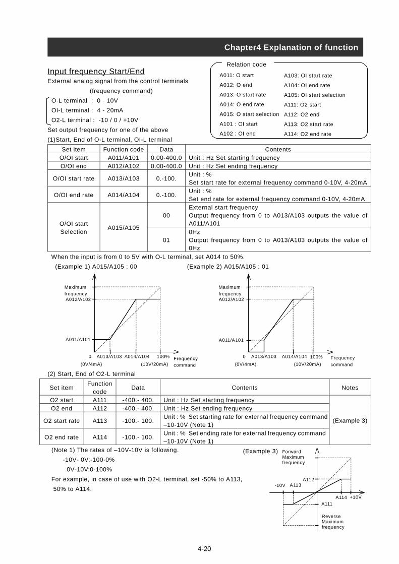
Input frequency Start/EndExternal analog signal from the control terminals
(frequency command)
O-L terminal : 0 - 10V
OI-L terminal : 4 - 20mA
O2-L terminal : -10 / 0 / +10V
Set output frequency for one of the above
(1)Start, End of O-L terminal, OI-L terminal
Set item Function code Data Contents
O/OI start A011/A101 0.00-400.0 Unit : Hz Set starting frequency
O/OI end A012/A102 0.00-400.0 Unit : Hz Set ending frequency
O/OI start rate A013/A103 0.-100.Unit : %Set start rate for external frequency command 0-10V, 4-20mA
O/OI end rate A014/A104 0.-100.Unit : %Set end rate for external frequency command 0-10V, 4-20mA
00External start frequencyOutput frequency from 0 to A013/A103 outputs the value ofA011/A101O/OI start
SelectionA015/A105
010HzOutput frequency from 0 to A013/A103 outputs the value of0Hz
When the input is from 0 to 5V with O-L terminal, set A014 to 50%.
(Example 1) A015/A105 : 00 (Example 2) A015/A105 : 01
(2) Start, End of
Set itemFu
O2 start
O2 end
O2 start rate
O2 end rate
(Note 1) The ra
-10V- 0V:-
0V-10V:0
For example, i
50% to A114.
Frequency
Maximum
frequencyA012/A102
A011/A101
0 A014/A104 100%
(0V/4Frequency
Maximum
frequencyA012/A102
A011/A101
0 A013/A103 A014/A104 100%
Chapter4 Explanation of function
A011: O start
A012: O end
A013: O start rate
A014: O end rate
A015: O start selection
A101 : OI start
A102 : OI end
Relation code
A103: OI start rate
A104: OI end rate
A105: OI start selection
A111: O2 start
A112: O2 end
A113: O2 start rate
A114: O2 end rate
A013/A103
4-20
O2-L terminal
nctioncode
Data Contents Notes
A111 -400.- 400. Unit : Hz Set starting frequency
A112 -400.- 400. Unit : Hz Set ending frequency
A113 -100.- 100.Unit : % Set starting rate for external frequency command–10-10V (Note 1)
A114 -100.- 100.Unit : % Set ending rate for external frequency command–10-10V (Note 1)
(Example 3)
tes of –10V-10V is following.
100-0%
-100%
n case of use with O2-L terminal, set -50% to A113,
commandmA) (10V/20mA) command(0V/4mA) (10V/20mA)
ForwardMaximumfrequency
ReverseMaximumfrequency
A111
A114
A113A112
+10V
-10V
(Example 3)
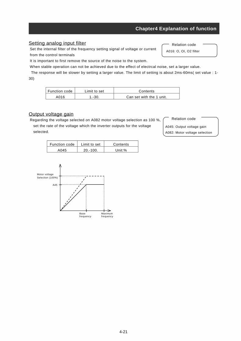
4-21
Setting analog input filter Set the internal filter of the frequency setting signal of voltage or current
from the control terminals
It is important to first remove the source of the noise to the system.
When stable operation can not be achieved due to the effect of electrcal noise, set a larger value.
The response will be slower by setting a larger value. The limit of setting is about 2ms-60ms( set value : 1-
30)
Function code Limit to set Contents
A016 1.-30. Can set with the 1 unit.
Output voltage gain Regarding the voltage selected on A082 motor voltage selection as 100 %,
set the rate of the voltage which the inverter outputs for the voltage
selected.
Function code Limit to set Contents
A045 20.-100. Unit:%
Chapter4 Explanation of function
A016: O, OI, O2 filter
Relation code
A0
A0
A45
Motor voltageSelection (100%)
Maximumfrequency
Basefrequency
Relation code
45: Output voltage gain
82: Motor voltage selection

4-22
Control system (V/f Characteristic) Set V/f (output voltage/output frequency) characteristic.
To change 1st /2nd control system (V/f characteristic), set
08(SET) to an intelligent input terminal and switch it ON.
Function code Data V/f characteristic
00 Constant torque characteristic(VC)
01 Reduced torque characteristic(VP1.7power)A044/A244
02 Free setting V/f characteristic
(1) Constant torque characteristic (VC)
Output voltage outputs proportionally to the output frequency.
Output voltage outputs proportionally from 0 to the base frequency, but the output voltage from the base
frequency to the maximum frequency is constant regardless of frequency.
(2) Reduced torque characteristic (VP1.7 power)
This characteristic can be used when a large starting torque isn’t required.
At low speeds, it can cause improvement of efficiency, low noise and low vibration because of lowering the
output voltage.
V/f characteristic is as follows.
Period :The limit from 0 to 10% of base frequency is the constant characteristic.
(Example) If the base frequency is 60Hz, the limit from 0 to 6Hz is constant characteristic.
Period :The limit from 10% of base frequency to base frequency is reduced torque characteristic.
The voltage is output in the curve of 1.7 power for frequency.
Period :The voltage is constant from the base frequency to the maximum frequency.
Chapter4 Explanation of function
A044/A244:1st/2nd control system
b100/b102/b104/b106/b108/b110/b112
: Free setting V/f frequency 1/2/3/4/5/6/7
b101/b103/b105/b107/b109/b111/b113
: Free setting V/f voltage 1/2/3/4/5/6/7
Relation code
Output frequency (Hz)
OutputVoltage (100%)
Basefrequency
Maximumfrequency
0
Basefrequency
Output voltage(100%)
Output frequencyMaximumfrequency
010% ofBasic frequency
VP(f1.7)VC
a b c
a
c
b
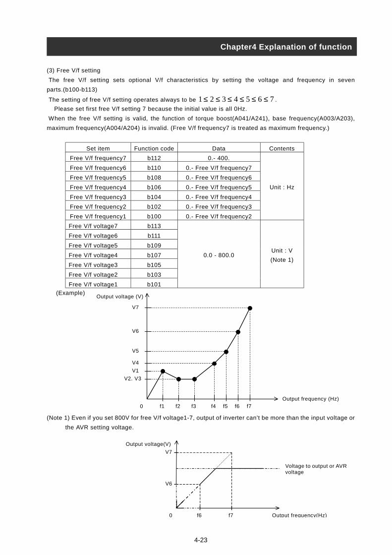
4-23
(3) Free V/f setting
The free V/f setting sets optional V/f characteristics by setting the voltage and frequency in seven
parts.(b100-b113)
The setting of free V/f setting operates always to be 7654321 ≤≤≤≤≤≤ .
Please set first free V/f setting 7 because the initial value is all 0Hz.
When the free V/f setting is valid, the function of torque boost(A041/A241), base frequency(A003/A203),
maximum frequency(A004/A204) is invalid. (Free V/f frequency7 is treated as maximum frequency.)
Set item Function code Data Contents
Free V/f frequency7 b112 0.- 400.
Free V/f frequency6 b110 0.- Free V/f frequency7
Free V/f frequency5 b108 0.- Free V/f frequency6
Free V/f frequency4 b106 0.- Free V/f frequency5
Free V/f frequency3 b104 0.- Free V/f frequency4
Free V/f frequency2 b102 0.- Free V/f frequency3
Free V/f frequency1 b100 0.- Free V/f frequency2
Unit : Hz
Free V/f voltage7 b113
Free V/f voltage6 b111
Free V/f voltage5 b109
Free V/f voltage4 b107
Free V/f voltage3 b105
Free V/f voltage2 b103
Free V/f voltage1 b101
0.0 - 800.0Unit : V
(Note 1)
(Example)
(Note 1) Even if you set 800V for free V/f voltage1-7, output of inverter can’t be more than the input voltage or
the AVR setting voltage.
Chapter4 Explanation of function
0 f6 f7
V6
V7
Voltage to output or AVRvoltage
Output voltage(V)
Output frequency(Hz)
Output frequency (Hz)
f1 f2 f3 f4 f5 f6 f70
V2, V3
V1
V5
V6
V7
V4
Output voltage (V)
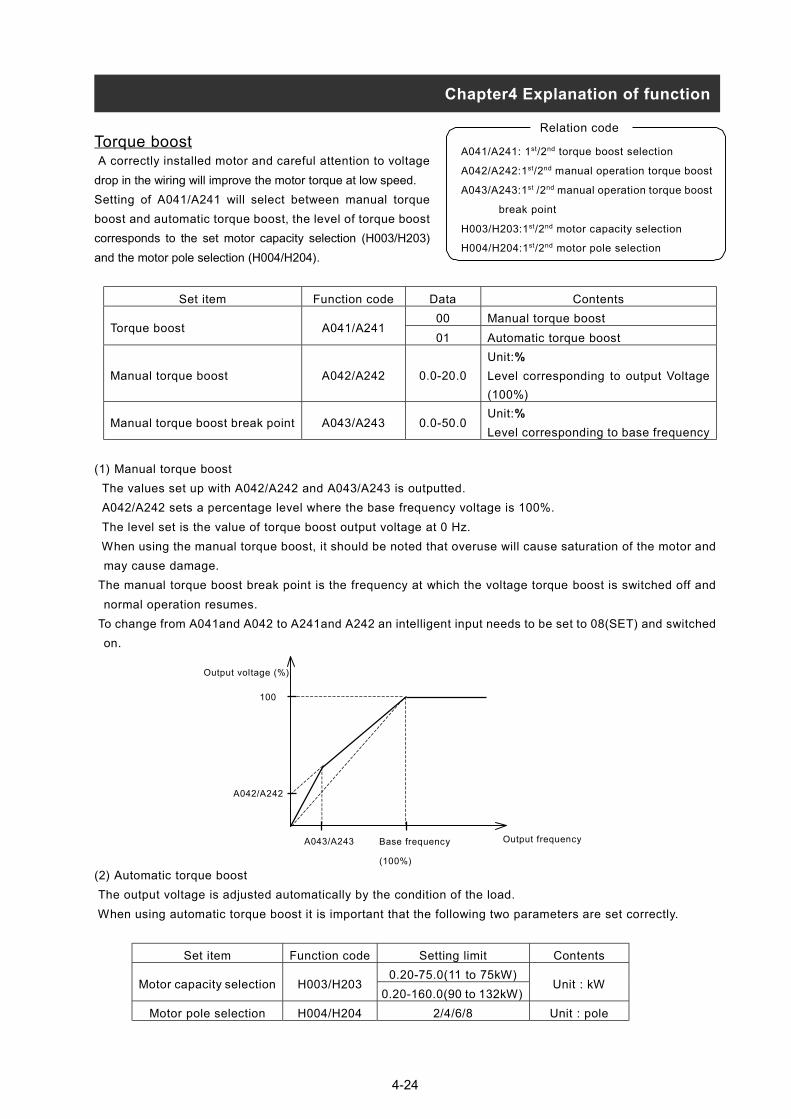
4-24
Torque boost A correctly installed motor and careful attention to voltage
drop in the wiring will improve the motor torque at low speed.
Setting of A041/A241 will select between manual torque
boost and automatic torque boost, the level of torque boost
corresponds to the set motor capacity selection (H003/H203)
and the motor pole selection (H004/H204).
Set item Function code Data Contents
00 Manual torque boostTorque boost A041/A241
01 Automatic torque boost
Manual torque boost A042/A242 0.0-20.0
Unit:%
Level corresponding to output Voltage
(100%)
Manual torque boost break point A043/A243 0.0-50.0Unit:%
Level corresponding to base frequency
(1) Manual torque boost
The values set up with A042/A242 and A043/A243 is outputted.
A042/A242 sets a percentage level where the base frequency voltage is 100%.
The level set is the value of torque boost output voltage at 0 Hz.
When using the manual torque boost, it should be noted that overuse will cause saturation of the motor and
may cause damage.
The manual torque boost break point is the frequency at which the voltage torque boost is switched off and
normal operation resumes.
To change from A041and A042 to A241and A242 an intelligent input needs to be set to 08(SET) and switched
on.
(2) Automatic torque boost
The output voltage is adjusted automatically by the condition of the load.
When using automatic torque boost it is important that the following two parameters are set correctly.
Set item Function code Setting limit Contents
0.20-75.0(11 to 75kW)Motor capacity selection H003/H203
0.20-160.0(90 to 132kW)Unit : kW
Motor pole selection H004/H204 2/4/6/8 Unit : pole
A041/A241: 1st/2nd torque boost selection
A042/A242:1st/2nd manual operation torque boost
A043/A243:1st /2nd manual operation torque boost
break point
H003/H203:1st/2nd motor capacity selection
H004/H204:1st/2nd motor pole selection
Relation code
Output frequencyBase frequency
(100%)
A042/A242
A043/A243
100
Output voltage (%)
Chapter4 Explanation of function

4-25
Direct current braking(DB) A dc voltage can be applied to the motor windings in order to lock
the motor shaft and avoid overun at low speeds.
There are two methods of activating the dc braking,
Outside which is through the intelligent input terminals and Inside
which is automatically started at a specific frequency.
Set itemFunctin
codeData Contents
00 Inside DC braking : invalidDC braking selection A051
01 Inside DC braking : valid
DC braking frequency A052 0.00-60.00Unit : HzWhen the output reaches the set frequency andInside DC braking is valid, DC braking is started.
DC braking late time A053 0.0-5.0
Unit : secondAfter DC braking time is reached, or DB terminalis ON, the late time is a delay before DC brakingis started.
DC braking power/Starting DC braking power
A054/A057 0.-70.Unt : %Weak (Zero current) –Strong (Inverter rating fairly 70% the DC current)
DC braking time A055 0.0-60.0
Unit : secondThe DC braking is stopped after this time delayhas elapsed. The time is tarted when the latetime has elapsed.
00 Edge movement (Example 1-6-a)DC braking edge/levelselection
A05601 Level movement (Example 1-6-b)
Starting DC braking time A058 0.0-60.0
Unit : secondIt is valid for inside DC braking.When operating command is ON, DC current isstarted.
0.5-12 Unit : kHz (11 to 75kW)DC braking carrierFrequency
A0590.5-8 Unit : kHz (90 to 132kW)
(1) DC braking carrier frequency
It is possible to alter the DC braking carrier frequency. However, if the DC braking carrier frequency is set
higher than 3kHz, the value of maximum braking power level is automatically reduced as follows.
Set DC braking carrier frequency with A059.
Chapter4 Explanation of function
A051: DC braking selection
A052: DC braking frequency
A053: DC braking late time
A054: DC braking power
A055: DC braking time
A056: DC braking edge/level selection
A057: Starting DC braking power
A058: Starting DC braking time
A059: DC braking carrier frequency
Relation code
0 3 5 7 9 11 12
Maximumbrakingpower (%)
Direct braking carrier frequency (kHz)
70
60
50
40
30
20
10
Direct braking power limiter
(58)(46)
(34)
(22)
(10)
0 3 5 7 8
70
60
50
40
30
20
10
Maximumbrakingpower (%)
Direct braking carrier frequency (kHz)
(50)
(25)
(10)
i) 11 to 75kW ii) 90 to 132kW

4-26
(2) Outside DC braking
Set 07(DB) to an intelligent input terminal.
DC braking is then switched by ON/OFF of DB terminal irrespective of DC braking selection A051.
Set strength of DC braking power with A054.
If DC braking late time A053 is set, the Inverter outpuit is cut off for this time period, the motor will be free
running.
After the late time passes, DC braking is started.
Please set DC braking time A055 or DC braking time by DB terminal paying attention to the heat of the motor.
Please set each setting in accordance with the system, after level action or edge action are selected with
A056.
(a) Edge operation (A056:00) (b) Level operation (A056:01)
(Example 1-a) (Example 1-b)
(Example 2-a) (Example 2-b)
(Example 3-a) (Example 3-b)
Chapter4 Explanation of function
FW
DB
Output frequency
Output frequency
FW
DB
FW
DB
Output frequency
A053
Free running
FW
DB
Output frequency
A055
FW
DB
Output frequency
A055
FW
DB
Outputfrequency
A053
Free running
A055

4-27
(3) Inside DC braking
When the inverter starts, and the DB terminal is not ON the inverter can operate dc braking.
When using inside DC braking, the DC braking selection A051 should be set 01.
Starting DC braking power is set with A057, DC braking time at starting is set with A058.
Braking power setting except starting time, set with A054.
If DC braking late time A053 is set and the dc braking frequency is reached, the operating command (FW) is
switched OFF. The inverter cuts the output and for the set time of A053, free running of the motor will occur.
After finishing the set time in A053, DC braking is started.
Set the frequency at which the DC braking will operate at with A052.
The operation of Edge/Level selection when using inside DC braking is different.
Edge action: Give priority to A055 DC braking action time, operate DC braking according to set time.
After turning operating command (FW) OFF, when output frequency reachs the set value of A052, during
setting A055 DC braking is run. Even if operation command is turned ON, during setting time of A055, DC
braking is run.(Example 5-a),(Example 6-a)
Level action: Give priority to operaing command, ignore DC braking time A055 and move to normal
operation. When operation command is turned ON during DC braking, set time of A055
is ignored and normal operation is restored. (Example 5-b), (Example 6-b)
(a) Edge action (b) Level action
i) When starting (Example 4-a) i) When starting (Example 4-b)
ii) When stopping (Example 5-a) ii) When stopping (Example 5-b)
iii) When stopping (Example 6-a) iii) When stopping (Example 6-b)
Chapter 4 Explanation of function
FW
Output frequency
A053
Free running
A055A052
FW
Output frequency
A053
Free running
A055A052
FW
Output frequency
A052A055
FW
Output frequency
A052A055
Output frequency
FW
A058
FW
Output frequency
A058
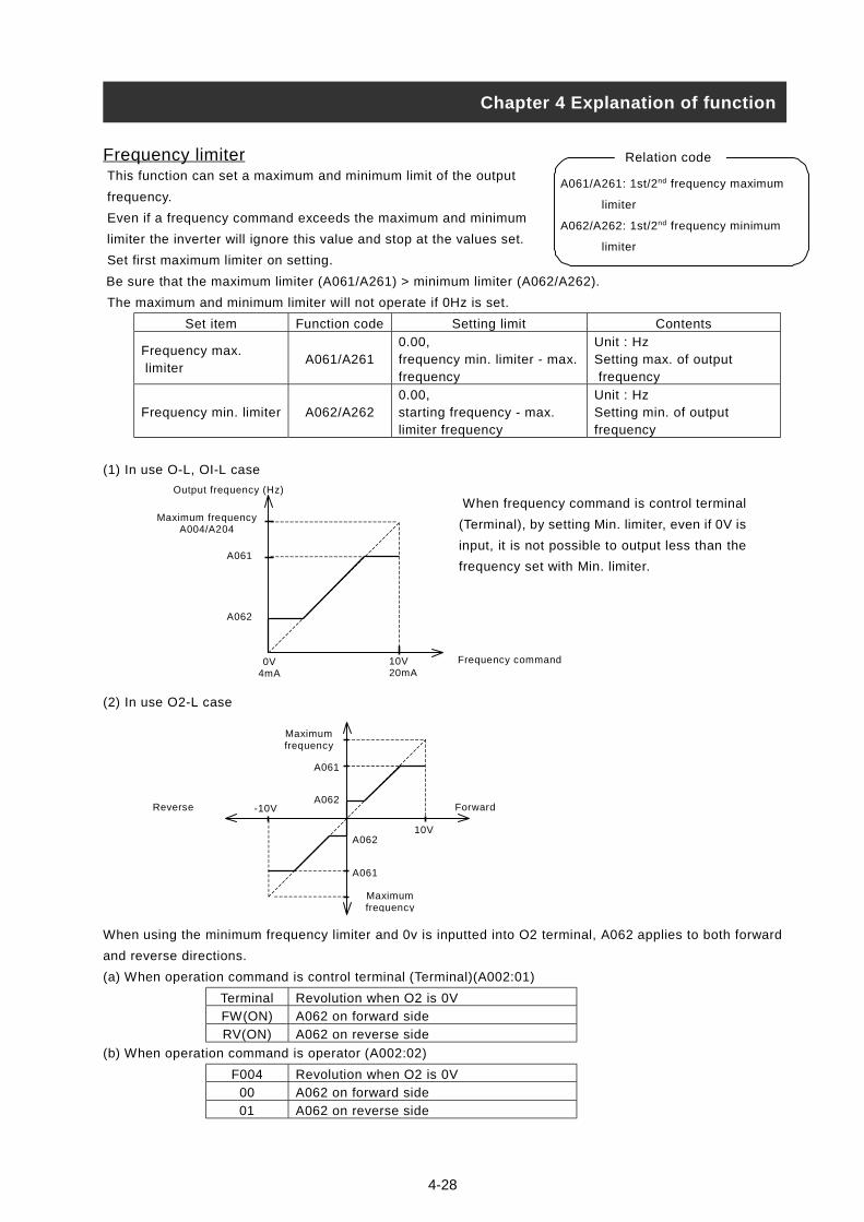
4-2
Frequency limiter This function can set a maximum and minimum limit of the output
frequency.
Even if a frequency command exceeds the maximum and minimum
limiter the inverter will ignore this value and stop at the values set.
Set first maximum limiter on setting.
Be sure that the maximum limiter (A061/A261) > minimum limiter (A062/A262).
The maximum and minimum limiter will not operate if 0Hz is set.
Set item Function code Setting limit Contents
Frequency max. limiter
A061/A2610.00,frequency min. limiter - max.frequency
Unit : HzSetting max. of output frequency
Frequency min. limiter A062/A2620.00,starting frequency - max.limiter frequency
Unit : HzSetting min. of outputfrequency
(1) In use
(2) In use O2-L case
When using the minimum frequency limiter and 0v is in
and reverse directions.
(a) When operation command is control terminal (Termi
Terminal Revolution when O2 is 0
FW(ON) A062 on forward side
RV(ON) A062 on reverse side
(b) When operation command is operator (A002:02)
F004 Revolution when O2 is 0
00 A062 on forward side
01 A062 on reverse side
Chapter 4 Explanation of function
A061/A261: 1st/2nd frequency maximum
limiter
A062/A262: 1st/2nd frequency minimum
limiter
Relation code
A062
A061
MaximumfrequencyA004/A204
Maximumfrequency
A062
A061
10V
-10VReverse
Maximum frequencyA004/A204
Frequency command0V4mA
10V20mA
A062
A061
When frequency command is control terminal
(Terminal), by setting Min. limiter, even if 0V is
input, it is not possible to output less than the
frequency set with Min. limiter.
Forward
O-L, OI-L case
Output frequency (Hz)
8
putted into O2 terminal, A062 applies to both forward
nal)(A002:01)
V
V
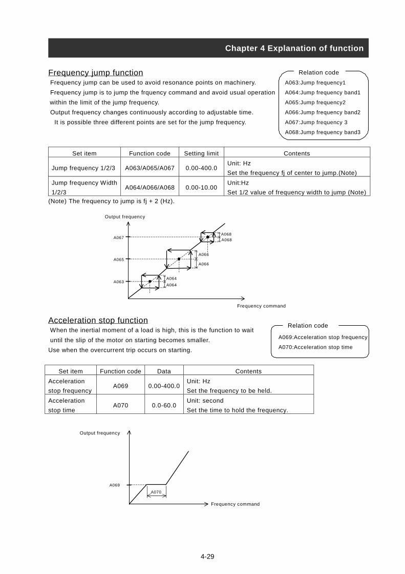
4-29
Frequency jump function Frequency jump can be used to avoid resonance points on machinery.
Frequency jump is to jump the frquency command and avoid usual operation
within the limit of the jump frequency.
Output frequency changes continuously according to adjustable time.
It is possible three different points are set for the jump frequency.
Set item Function code Setting limit Contents
Jump frequency 1/2/3 A063/A065/A067 0.00-400.0Unit: Hz
Set the frequency fj of center to jump.(Note)
Jump frequency Width
1/2/3A064/A066/A068 0.00-10.00
Unit:Hz
Set 1/2 value of frequency width to jump (Note)
(Note) The frequency to jump is fj + 2 (Hz).
Acceleration stop function When the inertial moment of a load is high, this is the function to wait
until the slip of the motor on starting becomes smaller.
Use when the overcurrent trip occurs on starting.
Set item Function code Data Contents
Acceleration
stop frequencyA069 0.00-400.0
Unit: Hz
Set the frequency to be held.
Acceleration
stop timeA070 0.0-60.0
Unit: second
Set the time to hold the frequency.
Chapter 4 Explanation of function
A069:Acceleration stop frequency
A070:Acceleration stop time
Relation code
A070
A069
Output frequency
Frequency command
Output frequency
Frequency command
A063
A065
A067
A064
A064
A066
A066
A068A068
A063:Jump frequency1
A064:Jump frequency band1
A065:Jump frequency2
A066:Jump frequency band2
A067:Jump frequency 3
A068:Jump frequency band3
Relation code
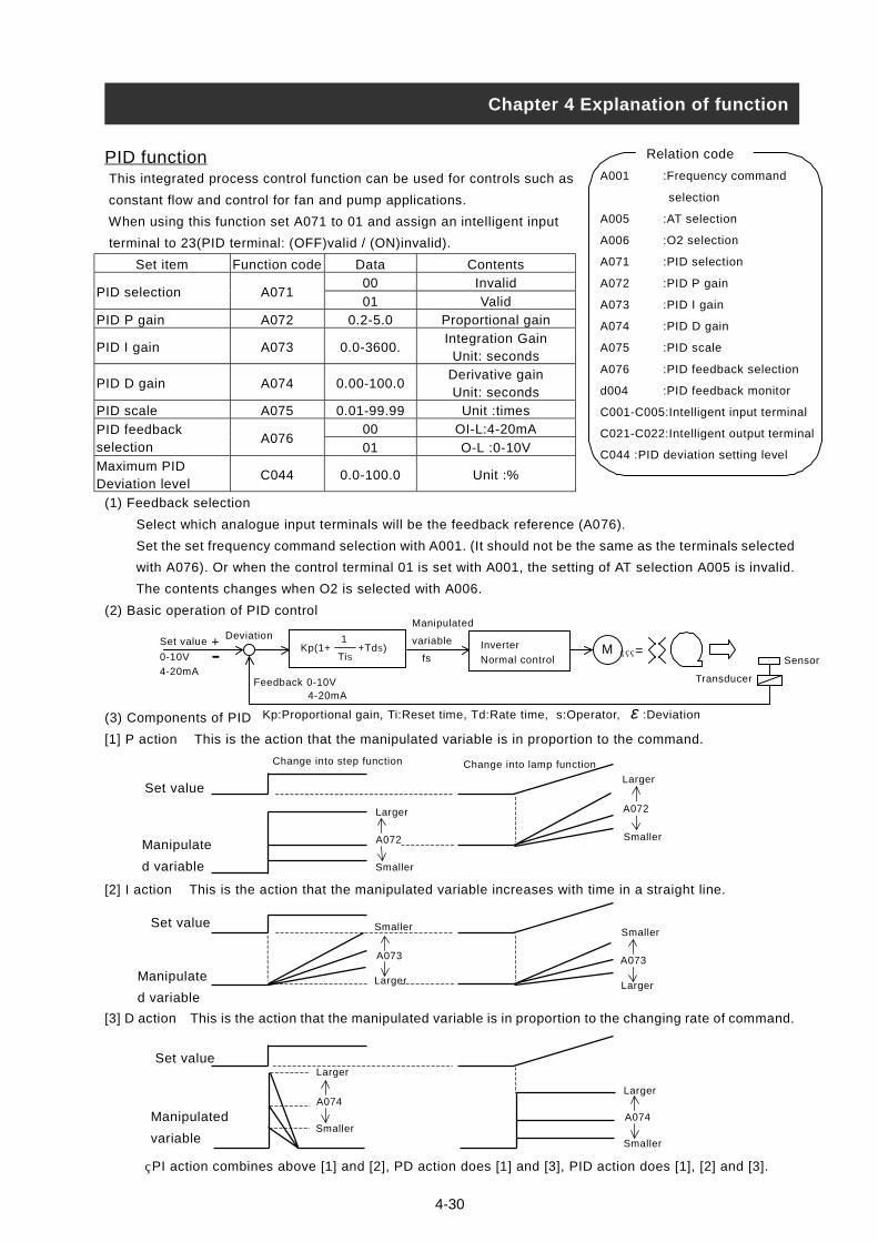
4-30
PID function This integrated process control function can be used for controls such as
constant flow and control for fan and pump applications.
When using this function set A071 to 01 and assign an intelligent input
terminal to 23(PID terminal: (OFF)valid / (ON)invalid).
Set item Function code Data Contents
00 InvalidPID selection A071
01 Valid
PID P gain A072 0.2-5.0 Proportional gain
PID I gain A073 0.0-3600.Integration Gain
Unit: seconds
PID D gain A074 0.00-100.0Derivative gainUnit: seconds
PID scale A075 0.01-99.99 Unit :times
00 OI-L:4-20mAPID feedbackselection
A07601 O-L :0-10V
Maximum PIDDeviation level
C044 0.0-100.0 Unit :%
(1) Feedback selection
Select which analogue input terminals will be the feedback reference (A076).
Set the set frequency command selection with A001. (It should not be the same as the terminals selected
with A076). Or when the control terminal 01 is set with A001, the setting of AT selection A005 is invalid.
The contents changes when O2 is selected with A006.
(2) Basic operation of PID control
(3) Components of PID
[1] P action This is the action that the manipulated variable is in proportion to the command.
[2] I action This is the action that the manipulated variable increases with time in a straight line.
[3] D action This is the action that the manipulated variable is in proportion to the changing rate of command.
A001 :Frequency command
selection
A005 :AT selection
A006 :O2 selection
A071 :PID selection
A072 :PID P gain
A073 :PID I gain
A074 :PID D gain
A075 :PID scale
A076 :PID feedback selection
d004 :PID feedback monitor
C001-C005:Intelligent input terminal
C021-C022:Intelligent output terminal
C044 :PID deviation setting level
Relation code
Sensor
1Kp(1+ +TdS) TiS
Inverter
Normal control
Manipulated
variable
fsM =
TransducerFeedback 0-10V 4-20mA
Set value
0-10V
4-20mA
+-
Deviation
Kp:Proportional gain, Ti:Reset time, Td:Rate time, s:Operator, ε :Deviation
Change into step function Change into lamp function
A072
Chapter 4 Explanation of function
Set value
Manipulate
d variable
Larger
Smaller
Larger
Smaller
A072
Set value
Manipulate
d variable
Smaller
Larger
Smaller
A073 A073
Larger
Set value
Manipulated
variable
Larger
Smaller
Larger
Smaller
PI action combines above [1] and [2], PD action does [1] and [3], PID action does [1], [2] and [3].
A074
A074

4-31
(4) The adjustment of gain
Please adjust each gain according to the state as the following, when the response on the functional
operation PID is not stable.
Inspite of changing command, the change of feedback signal is slow. Raise P gain.
The feedback signal changes instantly but is not stable. Lower P gain.
The command and feedback signal doesn’t coincide instantly. Lower I gain.
The feedback signal oscillates and is not stable. Raise I gain.
In spite of raising of P gain, the response is slow. Raise D gain.
When P gain is raised, the feedback signal oscillates and is not stable. Lower D gain.
(5) The Maximum PID Deviation Level/Output
It is possible to establish the maximum deviation level C044 on PID control. When the PID deviation
amount reaches the set level C044, it is possible to set an intelligent output.
C044 can be set from 0 to 100 and corresponds with the command; from 0 to maximum.
Assign 04 (OD) to intelligent output terminal 11, 12(C021, C022).
(6) Feedback monitor of PID
Feedback signal of PID can be monitored.
The monitor value can be displayed by the product of PID scale A075.
“Monitor display” = “Feedback (%)” x “A075 setting”
(7) PID integral reset
This is the function to clear integral value of PID action.
Assign 24(PIDC) to intelligent input terminal.
It is cleared whenever PIDC is turned ON.
Don’t turn absolutely ON PID terminal during PID action, because there is a possibility of overcurrent trip.
Turn ON PIDC terminal after turning OFF PID action.
Automatic energy-saving operation function This function regulates the inverter output power automatically to a
minimum while operating at constant speed.
This fits for the load of reduced torque characteristic of fans or pumps.
In case of operating by this function, set A085 to “01”.
A086 can adjust the automatic operation, response time.
Set item Function code Deta Contents
00 Normal operationOperationmode selection
A08501
Energy-savingoperation
Set item Function code Deta Response Accuracy
Energy savingresponse / accuracyadjustment
A086
0
100
Slow
Fast
High
Low
Chapter 4 Explanation of function
A085:Operation mode
selection
A086: Energy-saving response-
accuracy adjustment
Relation code

4-32
Two-stage acceleration and deceleration function (2CH) By setting this function, it is possible to change the rate of
acceleration and deceleration.
As methods to change the rate of acceleration and deceleration,
you can select the method of changing by intelligent input terminal
and the method of automatic changing by optional frequency.
In case of changing by intelligent input terminal, assign 09(2CH) to
an Intelligent input terminal.
Set item Function code Data Contents
Accelerationtime 2
A092/A292 0.01-3600. Unit : second (Example 1,2)
Decelerationtime 2
A093/A293 0.01-3600. Unit : second (Example 1,2)
00 Changing by intelligent input terminal 09 (2CH) (Example 1)Two-stageaccelerationanddecelerationselection
A094/A29401
Changing by two-stage acceleration and deceleration frequency(A095/A295, A096/A296) (Example 2)
Two-stageaccelerationfrequency
A095/A295 0.00-400.0Unit: Hz It is valid when two-stage acceleration and decelerationselection (A094/A294) is 01. (Example 2)
Two-stagedecelerationfrequency
A096/A296 0.00-400.0Unit: Hz It is valid when two-stage acceleration and decelerationselection (A094/A294) is 01. (Example 2)
(Example 1) In to set A094/A294 to 00 case (Example 2) In to set A094/A294 to 01 case
Chapter 4 Explanation of function
F002/F202: 1st /2nd acceleration 1
F003/F203: 1st /2nd deceleration time 1
A092/A292: 1st /2nd acceleration time 2
A093/A294: 1st /2nd deceleration time 2
A094/A294: 1st /2nd two-stage acceleration
and deceleration selection
A095/A295:1st /2nd two-stage acceleration
frequency
A096/A296: 1st /2nd two-stage deceleration
frequency
C001-C005: Intelligent input terminal
Relation code
FW
Acceleration2 Deceleration2
Acceleration Deceleration1
F002/F202
F003/F203A092/A292
A093/A293
A096/A29A095/A295
Output frequencyOutput frequency
2CH
FW
Acceleration2 Deceleration2
Acceleration1 Deceleration1
F002/F202
F003/F203A092/A292
A093/A293
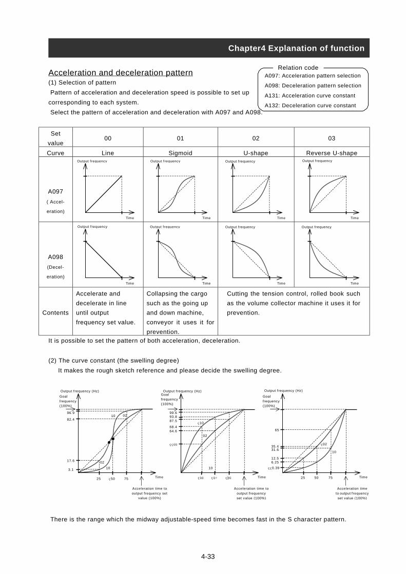
Acceleration and deceleration pattern(1) Selection of pattern
Pattern of acceleration and deceleration speed is possible to set up
corresponding to each system.
Select the pattern of acceleration and deceleration with A097 and A098.
Set
value00 01 02 03
Curve ne oid ape U-shape
A097
( Accel-
eration)
A098
(Decel-
eration)
Contents
It is poss
(2) The c
It ma
There is
Output
Goalfrequen(100%)
96.
82.
17.
3.1
Chapter4 Explanation of function
A097: Acceleration pattern selection
A098: Deceleration pattern selection
A131: Acceleration curve constant
A132: Deceleration curve constant
Relation code
LiOutput f requency
Accelerate and
decelerate in line
until output
frequency set value.
ible to set the pattern of
urve constant (the swelli
kes the rough sketch refe
the range which the mid
frequency (Hz)
cy
9
4
6
Accelera
output frvalue
25 50 75
10
02
10 02
SigmOutput f requency
4-33
Collapsing the cargo
such as the going up
and down machine,
conveyor it uses it for
prevention.
both acceleration, decele
ng degree)
rence and please decide
way adjustable-speed tim
Time
Time
tion time to
equency set (100%)
Output f requency (Hz)Goalfrequency(100%)
99.693.8
35
25 50
10
10
02
87.5
68.464.6
U-shOutput f requency
Cutting the tension cont
as the volume collector
prevention.
ration.
the swelling degree.
e becomes fast in the S ch
Time
Acceleration time to
output frequencyset value (100%)
75
Output f requency (H
Goalfrequency(100%)
65
35.4
0.39
31.6
12.56.25
Reverse Output f requency
Output f requency
Output f requency Output f requency Output f requencyTime
Timerol, rolled book
machine it uses
aracter pattern.
z)
Accel
to outpset va
25 50 75
10
02
Time
Time
Time Time Timesuch
it for
Time
eration time
ut f requencylue (100%)
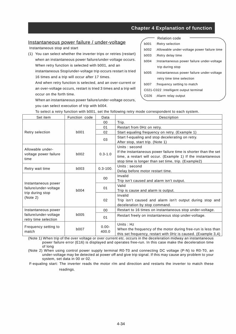
4-34
Instantaneous power failure / under-voltage Instantaneous stop and start
(1) You can select whether the inverter trips or retries (restart)
when an instantaneous power failure/under-voltage occurs.
When retry function is selected with b001, and an
instantaneous Stop/under-voltage trip occurs restart is tried
16 times and a trip will occur after 17 times.
And when retry function is selected, and an over-current or
an over-voltage occurs, restart is tried 3 times and a trip will
occur on the forth time.
When an instantaneous power failure/under-voltage occurs,
you can select execution of trip with b004.
To select a retry function with b001, set the following retry mode correspondent to each system.
Set item Function code Data Description
00 Trip.
01 Restart from 0Hz on retry.
02 Start equaling frequency on retry. (Example 1)Retry selection b001
03Start f-equaling and stop decelerating on retry.After stop, start trip. (Note 1)
Allowable under-voltage power failuretime
b002 0.3-1.0
Units : secondIf the instantaneous power failure time is shorter than the settime, a restart will occur. (Example 1) If the instantaneousstop time is longer than set time, trip. (Example2)
Retry wait time b003 0.3-100.Units : secondDelay before motor restart time.
00InvalidTrip isn’t caused and alarm isn’t output.
01ValidTrip is cause and alarm is output.
Instantaneous powerfailure/under-voltagetrip during stop(Note 2)
b004
02InvalidTrip isn’t caused and alarm isn’t output during stop anddeceleration by stop command.
00 Restart to 16 times on instantaneous stop under-voltage.Instantaneous powerfailure/under-voltageretry time selection
b00501 Restart freely on instantaneous stop under-voltage.
Frequency setting tomatch
b0070.00-400.0
Units : HzWhen the frequency of the motor during free-run is less thanthis set frequency, restart with 0Hz is caused. (Example 3,4)
(Note 1) When trip of the over voltage or over current etc. occurs in the deceleration midway an instantaneouspower failure error (E16) is displayed and operates free-run. In this case make the deceleration timeof long
(Note 2) When using control power supply terminal R0-T0 and connecting DC voltage (P-N) to R0-T0, anunder-voltage may be detected at power off and give trip signal. If this may cause any problem to yoursystem, set data in 00 or 02.
F-equaling start: The inverter reads the motor r/m and direction and restarts the inverter to match these
readings.
Chapter 4 Explanation of function
b001 :Retry selection
b002 :Allowable under-voltage power failure time
b003 :Retry delay time
b004 :Instantaneous power failure under-voltage
trip during stop
b005 :Instantaneous power failure under-voltage
retry time time selection
b007 :frequency setting to match
C021-C022 :Intelligent output terminal
C026 :Alarm relay output
Relation code

Retry function (b001: 02): The timing chart in case of selection is following.
(2) Instantaneous power failure during stop alarm output during under-voltage
Select yes/no of alarm output when instantaneous power failure or under-voltage occurs with b004.
Alarm outputs while control power of inverter remains.
• Alarm output at an instantaneous power failure and under-voltage during standstill. Standard (Example 5-7). Alarm signal performance when connecting DC voltage (P-N) to R0-T0 terminal. (Example 8-10).
(3
(4
After wait for t2 seconds according to t0 < t1, resta
t0 t2t1
Free-run
Power supply
Invertert t
Revolving timeof
(Example 1)
t0t1
Free-run
Power supply
Inverter output
Revolving time ofmotor
(Example 2)
t0 :Instantaneous stop power failuret1 :Allowable under-voltage power failure time(b002)t2 :Retry waits time(b003)
Chapter 4 Explanation of function
(example 5) b004:00 inverter : stand still (example 8) b004:00 inverter : stand stillinverter : run inverter : run
t0 t2
Free-run
Power supply
Inverteroutput
Motor frequency(revolution time)
0
b007
F-equaling start
t0 t2
Free-run
Power supply
InverteroutputMotor frequency(revolution time)
0
b007
0Hz start
(Example 3) Motor frequency(revolution time) >b007
4-35
) It is possible to use an output by assigning the signal (I
during under-voltage to an intelligent output terminal
(C026).
) If the instantaneous power failure time is longer than 1
power supply
running command
inverter output
AL
IPON
OFF
ON
OFF
ON
OFF
ON
OFF
(example 6) b004:01
power supply
running command
inverter output
AL
IPON
OFF
ON
OFF
ON
OFF
ON
OFF
inverter : stand still
(example 7) b004:02
power supply
running command
inverter output
AL
IPON
OFF
ON
OFF
ON
OFF
ON
OFF
inverter : stand still
power supply
running command
inverter output
AL
IPON
OFF
ON
OFF
ON
OFF
ON
OFF
inverter : run
power supply
running command
inverter output
AL
IPON
OFF
ON
OFF
ON
OFF
ON
OFF
inverter : run
power supply
running command
inverter output
AL
IPON
OFF
ON
OFF
ON
OFF
ON
OFF
rt. Trip according to t0 > t1.
(Example 4) Motor frequency (revolution time) <b007
P: 08) during instantaneous stop, by setting (UV: 09)
11, 12(C021, C022) or alarm relay output terminal
second, please refer to the pages 4-48 Reset (RS).
power supply
running command
inverter output
AL
IPON
OFF
ON
OFF
ON
OFF
ON
OFF
(example 9) b004:01
power supply
running command
inverter output
AL
IPON
OFF
ON
OFF
ON
OFF
ON
OFF
inverter : stand still
(example 10) b004:02
power supply
running command
inverter output
AL
IPON
OFF
ON
OFF
ON
OFF
ON
OFF
inverter : stand still
power supply
running command
inverter output
AL
IPON
OFF
ON
OFF
ON
OFF
ON
OFF
inverter : run
power supply
running command
inverter output
AL
IPON
OFF
ON
OFF
ON
OFF
ON
OFF
inverter : run
power supply
running command
inverter output
AL
IPON
OFF
ON
OFF
ON
OFF
ON
OFF
under-voltage
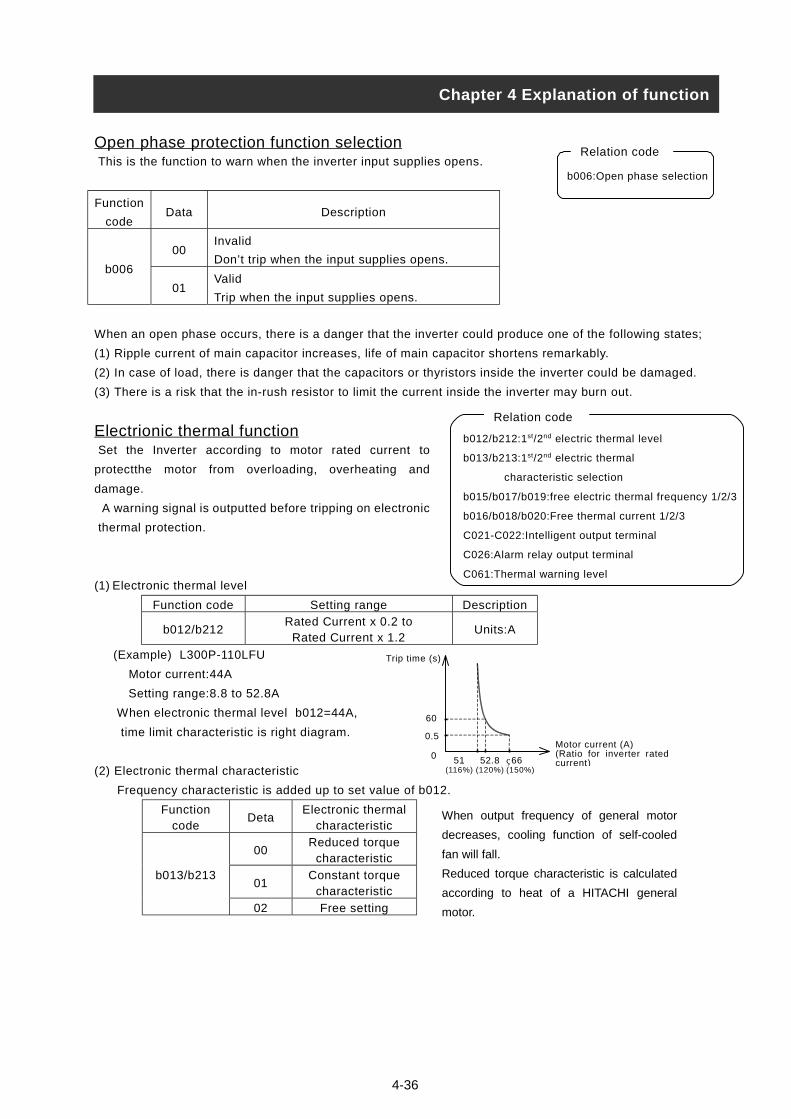
4-36
Open phase protection function selection This is the function to warn when the inverter input supplies opens.
Function
codeData Description
00Invalid
Don’t trip when the input supplies opens.b006
01Valid
Trip when the input supplies opens.
When an open phase occurs, there is a danger that the inverter could produce one of the following states;
(1) Ripple current of main capacitor increases, life of main capacitor shortens remarkably.
(2) In case of load, there is danger that the capacitors or thyristors inside the inverter could be damaged.
(3) There is a risk that the in-rush resistor to limit the current inside the inverter may burn out.
Electrionic thermal function Set the Inverter according to motor rated current to
protectthe motor from overloading, overheating and
damage.
A warning signal is outputted before tripping on electronic
thermal protection.
(1) Electronic thermal level
Function code Setting range Description
b012/b212Rated Current x 0.2 to
Rated Current x 1.2Units:A
(Example) L300P-110LFU
Motor current:44A
Setting range:8.8 to 52.8A
When electronic thermal level b012=44A,
time limit characteristic is right diagram.
(2) Electronic thermal characteristic
Frequency characteristic is added up to set value of b012.
Functioncode
DetaElectronic thermal
characteristic
00Reduced torque
characteristic
01Constant torque
characteristicb013/b213
02 Free setting
b006:Open phase selection
Relation code
b012/b212:1st/2nd electric thermal level
b013/b213:1st/2nd electric thermal
characteristic selection
b015/b017/b019:free electric thermal frequency 1/2/3
b016/b018/b020:Free thermal current 1/2/3
C021-C022:Intelligent output terminal
C026:Alarm relay output terminal
C061:Thermal warning level
Relation code
Trip time (s)
Motor current (A)(Ratio for inverter ratedcurrent)
60
0.5
51(116%)
0 52.8(120%)
66(150%)
Chapter 4 Explanation of function
When output frequency of general motor
decreases, cooling function of self-cooled
fan will fall.
Reduced torque characteristic is calculated
according to heat of a HITACHI general
motor.
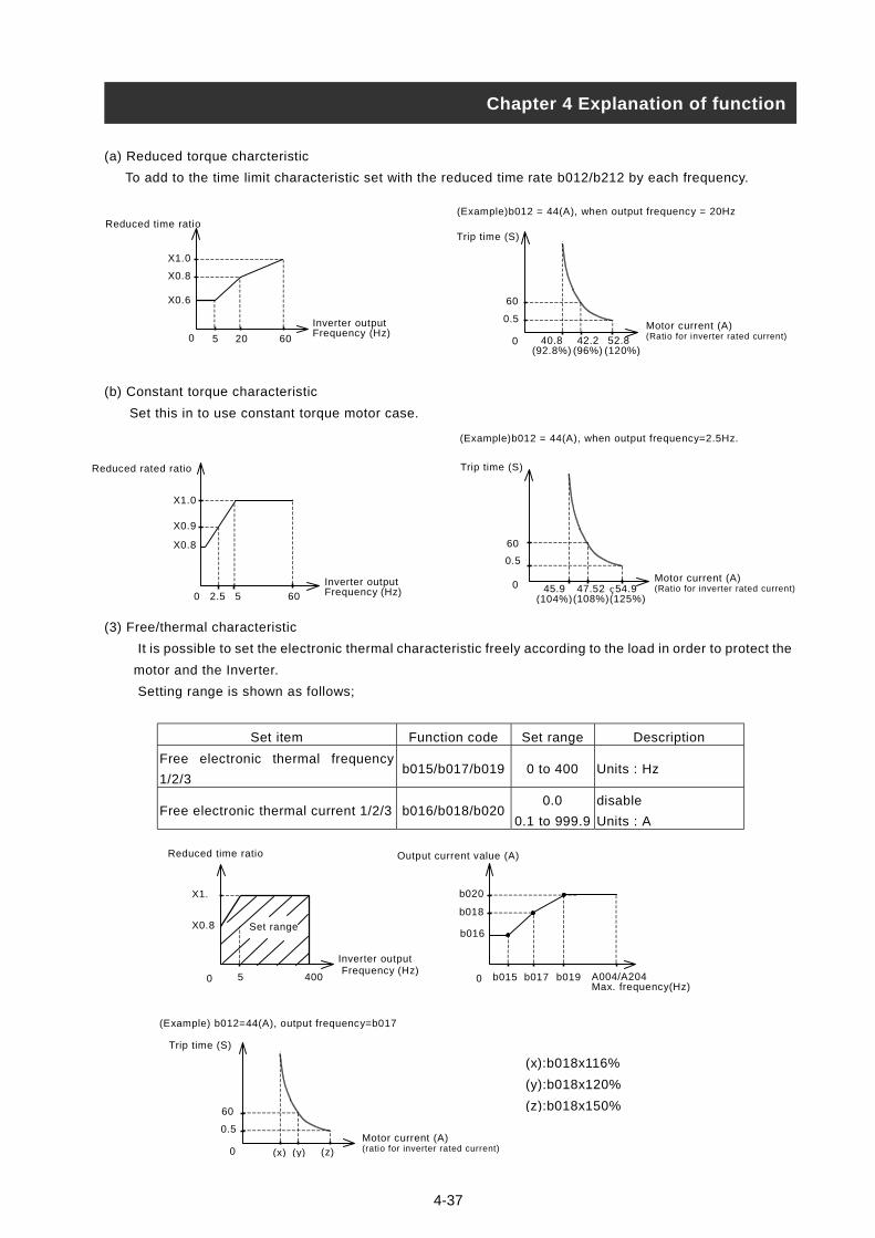
4-37
(a) Reduced torque charcteristic
To add to the time limit characteristic set with the reduced time rate b012/b212 by each frequency.
(b) Constant torque characteristic
Set this in to use constant torque motor case.
(3) Free/thermal characteristic
It is possible to set the electronic thermal characteristic freely according to the load in order to protect the
motor and the Inverter.
Setting range is shown as follows;
Set item Function code Set range Description
Free electronic thermal frequency
1/2/3b015/b017/b019 0 to 400 Units : Hz
Free electronic thermal current 1/2/3 b016/b018/b0200.0
0.1 to 999.9
disable
Units : A
Reduced rated ratio
Inverter outputFrequency (Hz)
X1.0
0 60
X0.9
X0.8
52.5
Reduced time ratio
Inverter outputFrequency (Hz)
X1.0
5 20 60
X0.8
X0.6
0Motor current (A)(Ratio for inverter rated current)
(Example)b012 = 44(A), when output frequency = 20Hz
Trip time (S)
60
0.5
40.8(92.8%)
42.2(96%)
52.8(120%)
0
(Example)b012 = 44(A), when output frequency=2.5Hz.
Trip time (S)
Motor current (A)(Ratio for inverter rated current)
60
0.5
45.9(104%)
47.52(108%)
54.9(125%)
0
(Example) b012=44(A), output frequency=b017
Trip time (S)
Motor current (A)(ratio for inverter rated current)
60
0.5
(x) (y) (z)0
Inverter output Frequency (Hz)
Reduced time ratio
X1.
5 400
X0.8
0 A004/A204Max. frequency(Hz)
b020
b018
b016
b015 b017 b0190
Output current value (A)
Set range
Chapter 4 Explanation of function
(x):b018x116%
(y):b018x120%
(z):b018x150%

4-38
(3) Thermal warning
A warning signal is outputted before overheat protection by the electronic thermal protection occurs.
Warning level is set with C061.
Assign 13(THM) to an intelligent output terminal (C021, C022) or the alarm relay output (C061).
Function
codeData Description
C0610.
1.-100.
Thermal warning is noneffective
Units : %
Overload restriction/Overload advance notice(1) Overload restriction
The Inverter monitors the motor current on acceleration and constant
speed,
When the inverter reaches the overload restriction level, the Inverter
will reduce the output frequency automatically to restrict the overload.
This function prevents an over-current trip by inertia during acceleration
or radical changes in load at constant speed.
Two kinds of overload restriction function are set with b021, b022, b023
and b024, b025, b026.
To change b021, b022, b023 and b024, b025, b026, assign 39(OLR)
to an intelligent input terminal.
The current value this function operates at is set in overload restriction
level.
The overload restriction constant is the time to decelerate to 0Hz from max. frequ
b021, b022, b023 and b024, b025, b026 is changed with OLR.
As this function operates, the acceleration time is longer than setting time.
If the overload restriction constant is set too short, in spite of accelerating, an ove
regenerative enegy from the motor on automatic deceleration by this function.
When this function operates in the midst of accelerating, the frequency will not re
Inverter will adjust in the following way.
Make acceleration time longer.
Raise torque boost.
Raise overload restriction level.
Set item Function code Data Descr
00 Invalid
01 Acceleration/valid on cOverloadrestrictionSelection.
b021/b024
02 Valid on constant spee
OverloadrestrictionLevel.
b022/b025Rated current x 0.5 to
Rated current x 1.5Units :ACurrent value overload
OverloadrestrictionConstant.
b023/b026 0.1 to 30.0Units :secondDeceleration time whenOperates.
b021:O
b022:O
b023:O
b024:O
b025:O
b026:O
C001-
C021-
C026:
C040:
o
C041:
Chapter 4 Explanation of function
Relation code
ency.
r-voltage trip is caused with
ach the goal frequency, the
iption
onstant speed.
d.
restriction operates.
overload restriction
verload restriction selection
verload restriction level
verload restriction constant
verload restriction 2 selection
verload restriction level2
verload restriction constant2
C005:Intelligent input terminal
C022:Intelligent output terminal
Alarm relay output setting
Overload advance notice signal
utput mode
Overload notices level

(2) Overload advance notice
When the load is high, it is possible to adjust the load again by outputting an overload advance notice.
It is used to prevent damage to the machine from too much load, i.e. baggage on a conveyor, the Inverter
overload protection will operate.
Assign 03(OL) to an intelligent output terminal 11, 12 or the alarm relay output terminal.
Set itemFunction
codeData Description
00 On acceleration, constant speed, this is valid.Overload
advance notice
signal output
mode selection
C040
01 On constant speed only, this is valid.
0.0 Overload advance notice is non-effective.
Overload
advance notice
level
C041 0.1 to
Rated current x
2.0
Units: A
As load reaches overload advance notice level,
OL signal is output.
Inverter output frequency
Overload restriction levelb022/b025
Output frequency
Goal frequencyF001
Deceleration set with
overload restriction constant
b023/b026
Maximum frequency A004/A204
Overload restriction levelb022/b025
Chapter 4 Explanation of function
Overload advance notice levelC040
4-39
Output current
OL
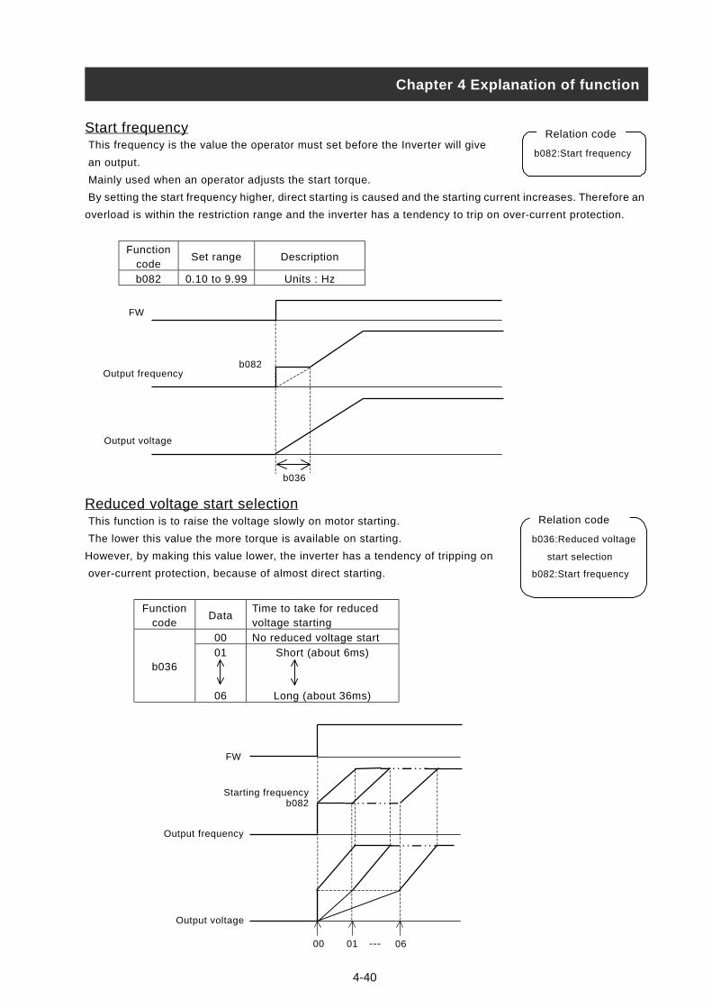
4-40
Start frequency This frequency is the value the operator must set before the Inverter will give
an output.
Mainly used when an operator adjusts the start torque.
By setting the start frequency higher, direct starting is caused and the starting current increases. Therefore an
overload is within the restriction range and the inverter has a tendency to trip on over-current protection.
Functioncode
Set range Description
b082 0.10 to 9.99 Units : Hz
Reduced voltage start selection This function is to raise the voltage slowly on motor starting.
The lower this value the more torque is available on starting.
However, by making this value lower, the inverter has a tendency of tripping on
over-current protection, because of almost direct starting.
Functioncode
DataTime to take for reducedvoltage starting
00 No reduced voltage start
b03601
06
Short (about 6ms)
Long (about 36ms)
Chapter 4 Explanation of function
b082:Start frequency
Relation code
FW
Output frequency
Output voltage
b082
b036
FW
Output frequency
Output voltage
Starting frequencyb082
00 01 06---
Relation code
b036:Reduced voltage
start selection
b082:Start frequency

4-41
BRD (dynamic braking) function This function only operates with the L300P - 15kW and lower, as they have the
built-in BRD.
This function is to consume regenerative energy from the motor as heat by the
use of an external resistor.
Regeneration occurs when the motor is decelerated to quickly and the motor turns into a generator and
voltage flows back into the Inverter.
To use the BRD function, set following condition.
Set itemFunction
codeData Description
0.0 BRD don’t operate.
BRD usage
Ratiob090
0.1-100.0
The usage ratio of BRD is set by 0.1% unit.
When inverter exceeds the usage ratio, trip.
(t1+t2+t3
100 secon
00 BRD don’t operate.
01During run: valid (BRD operates.)
During stop: invalid (BRD doesn’t operate.)
Selection of
BRDb095
02 During run, stop, valid (BRD operates.)
(Note 1)
330-380Units: V In case of 200V class inverter, settin
BRD ON
Levelb096
(Note 1)
660-760Units: V In case of 400V class inverter, settin
(Note 1) BRD ON level is the voltage setting of the DC (direct current) voltage of t
Cooling fan operating selection You can select whether the fan operates continuously or operates only when the
inverter is in the running operation.
Function
codeData Description
00 Always run
b09201
Only during run
However, inverter operates for five minutes after
power ON, and for five minutes after inverter
operation stops.
Chapter 4 Explanation of function
BRD action
t2
ON ONON
100 second
t1 t3
b090: BRD usage ratio
b095: BRD selection
b096: BRD On level
Relation code
)X100
Usage ratio (%) =
d
g is valid.
g is valid.
he inverter.
b092:Cooling fan
operation selection
Relation code

4-42
Intelligent input terminal setting It is possible to operate functions by assigning those functions to the
intelligent input terminals 1-5 (C001-C005).
The intelligent input terminals 1-5 can be selected individually whether the contact input specification is either
a NO or a NC contact.
Two or more intelligent input terminals can’t be assigned to be the same function.
If an intelligent input is assigned a function which is already assigned to another terminal it will automatically
be restored back to the setting before.
Function Code Data Description Reference item Page
01 RV:Reverse command Operation run 4-14
02 CF1:Multi-speed 1 (binary operation)
03 CF2:Multi-speed 2 (binary operation
04 CF3:Multi-speed 3 (binary operation)
05 CF4:Multi-speed 4 (binary operation)
Multi-speed operation function 4-43
06 JG:Jogging Jogging operation 4-44
07 DB:External DC braking DC braking(external DC braking) 4-26
08 SET:2nd Set of Motor Data 2nd Set of Motor Data 4-45
09 2CH:Two-stage adjustable-speed Two-stage adjustable-speed function 4-32
11 FRS:Free-run stop Free-run stop 4-46
12 EXT:External trip External trip 4-50
13 USP:Unattended start protection Unattended start protection function 4-49
14 CS:Commercial change Commercial change 4-47
15 SFT:Software lock (control terminal) Software lock 4-45
16 AT:analog input voltage/current select Analog external input 4-19
18 RS:Reset inverter Reset inverter 4-48
20 STA:3 wire start
21 STP:3 wire stop
22 F/R:3 wire direction
3 wire input function 4-50
23 PID:PID selection (valid/invalid)
24 PIDC:PID integrating resetPID function 4-30
27 UP:Remote control UP function
28 DWN:Remote control DOWN function
29 UDC:Remote control data clear
UP/DOWN function 4-49
31 OPE:force operation ope force operation ope function 4-55
32 SF1:Multi-speed 1 (bit run)
33 SF2:Multi-speed 2 (bit run)
34 SF3:Multi-speed 3 (bit run)
35 SF4:Multi-speed 4 (bit run)
36 SF5:Multi-speed 5 (bit run)
37 SF6:Multi-speed 6 (bit run)
38 SF7:Multi-speed 7 (bit run)
Multi-speed operation function 4-43
39 OLR:Overload restriction change Overload restriction 4-38
C001- C005
no NO:No assign - -
Input terminal a/b (NO/NC) selectionIt is possible to set a contact input or b contact input to
intelligent input terminals 1-5 and FW terminals individually.
Set item Function code Data Description
00 A contact(NO)Intelligent input 1-5a/b(NO/NC)selection
C011-C01501 B contact(NC)
00 A contact(NO)Input FWa/b(NO/NC)selection
C01901 B contact(NC)
C001-C005: Intelligent input terminal
Relation code
C011-C015: Intelligent input a/b (NO/NC)
selection
C019 :Input FW a/b (NO/NC) selection
Relation code
a contact: “ON” with Close, “OFF” with Open
b contact: “ON” with Open, “OFF” with Close
RS terminal can set only a contact.
Chapter 4 Explanation of function

4-43
Multi-speed operation function It is possible to set multiple operation speeds and switch between the
speeds with the terminals.
Multi-speed operation can be selected by binary operation(max. 16
speeds) with 4 terminals or by bit operation (max. 6 speeds) with 5
terminals.
Set item Functin code Set value Description
00 Change to binary operation 16 speed.Multi-speedselection
A01901 Change to bit operation 6 speed
Multi-speed0-15
A020/A220-A0350.00, start frequency-
max. frequencyUnits:Hz
(1) Binary operation
It is possible to set multi-speed 0 to 15 by selecting 02 to 05 (CF1 to CF4) on the intelligent input terminals.
Set frequency setting for speed 1 to 15 with A021-A035.
Set 0 speed with A020/A220 or F001 when frequency command is operator.
Or when frequency command is control terminal (Terminal), set with O, OI, O2 terminal.
Multi-speed CF4 CF3 CF2 CF1
0 speed OFF OFF OFF OFF
1 speed OFF OFF OFF ON
2 speed OFF OFF ON OFF
3 speed OFF OFF ON ON
4 speed OFF ON OFF OFF
5 speed OFF ON OFF ON
6 speed OFF ON ON OFF
7 speed OFF ON ON ON
8 speed ON OFF OFF OFF
9 speed ON OFF OFF ON
10 speed ON OFF ON OFF
11 speed ON OFF ON ON
12 speed ON ON OFF OFF
13 speed ON ON OFF ON
14 speed ON ON ON OFF
15 speed ON ON ON ON
(2) Bit operation
It is possible to set multi-speed 0 to 5 by assigning 32 to 38 (SF1-SF7) to the intelligent input terminals.
Set frequency SF1-SF7 to A021-A027.
Multi-speed SF7 SF6 SF5 SF4 SF3 SF2 SF1
0 speed OFF OFF OFF OFF OFF OFF OFF
1 speed - - - - - - ON
2 speed - - - - - ON OFF
3 speed - - - - ON OFF OFF
4 speed - - - ON OFF OFF OFF
5 speed - - ON OFF OFF OFF OFF
6 speed - ON OFF OFF OFF OFF OFF
7 speed ON OFF OFF OFF OFF OFF OFF
When each terminal turns ON simultaneously, the lower
number has priority. In order for the inverter to operate both
the frequency and the RUN operation (FW,RV) must be applied.
The L300P series can allocate it to 5 biggest terminals simultaneously.
Chapter 4 Explanation of function
A019: Multi-speed selection
A020/A220: 1st/2nd/multi-stage speed
zero speed
A021-A035: Multi-speed 1-15
C001-C005: Intelligent input terminal
Relation code
2 speed
1 speed
11 speed
3 speed5 speed
6 speed
7 speed
4 speed
8 speed
9 speed
10 speed12 speed
13 speed
14 speed
15 speed
0 speed
Frequency command fromoperator or analog externalinput terminal.
CF1
CF2
CF3
CF4
FW
1 speed
SF1
SF2
SF3
SF4
SF5
FW
0 speed
1 speed2 speed
3 speed
4 speed5 speed
Frequency command fromoperator or analog externalinput terminal

4-44
Jogging operation(JG) This function can be used to rotate the motor in small steps to
allow fine-tuning.
Set an intelligent input terminal to 06(JG).
(1) Jogging frequency
The jogging operation does not use acceleration, therefore it would be advisable to set the jogging frequency
to limit the starting current to a minimum or tripping may occur. Adjust A038 to the jogging frequency required.
Function
codeData Description
A038 0.0, start frequency-9.99 Units:Hz
(2) Jogging operation selection
Functioncode
Data DescriptionJogging operation during run
Valid / Invalid
00 Free-run on jogging stop
01 Decelerating stop on jogging stop.
02 Direct braking on jogging stop.
Invalid (Example 1)(Note 1)
03 Free-run on jogging stop.(example2)
04 Decelerating stop on jogging stop.
A039(Note 2)
05 Direct braking on jogging stop.
Valid (Example 2)(Note 1)
(Note 1) When using the jogging function, turn FW terminal or RV terminal ON after the JG terminal is turned
ON. (It is the same when the operation command point is from the operator.)
(Note 2) In the case that the setting of A039 is 02 or 05, data setting of DB is necessary.
When DB data is not setting,the inverter operates Free-run.
Chapter 4 Explanation of function
A038 : Jogging frequency
A039 : Jogging selection
C001-C005 : Intelligent input setting
Relation code
Free-run
JG
FW
JG
FW
(Example 1) (Example 2)
Frequency commandFrequency command
When setting of A039 is 00,01 or 02 and FW
signal is turned ON beforehand, the inverter
doesn’t operate jogging.
When setting of A039 is 03,04 or 05 and FW
terminal is turned ON beforehand, the inverter
operates jogging. But jogging terminal is turned
ON beforehand, the inverter output is cut off.
JG
FW
RV
Output frequencyA038
0
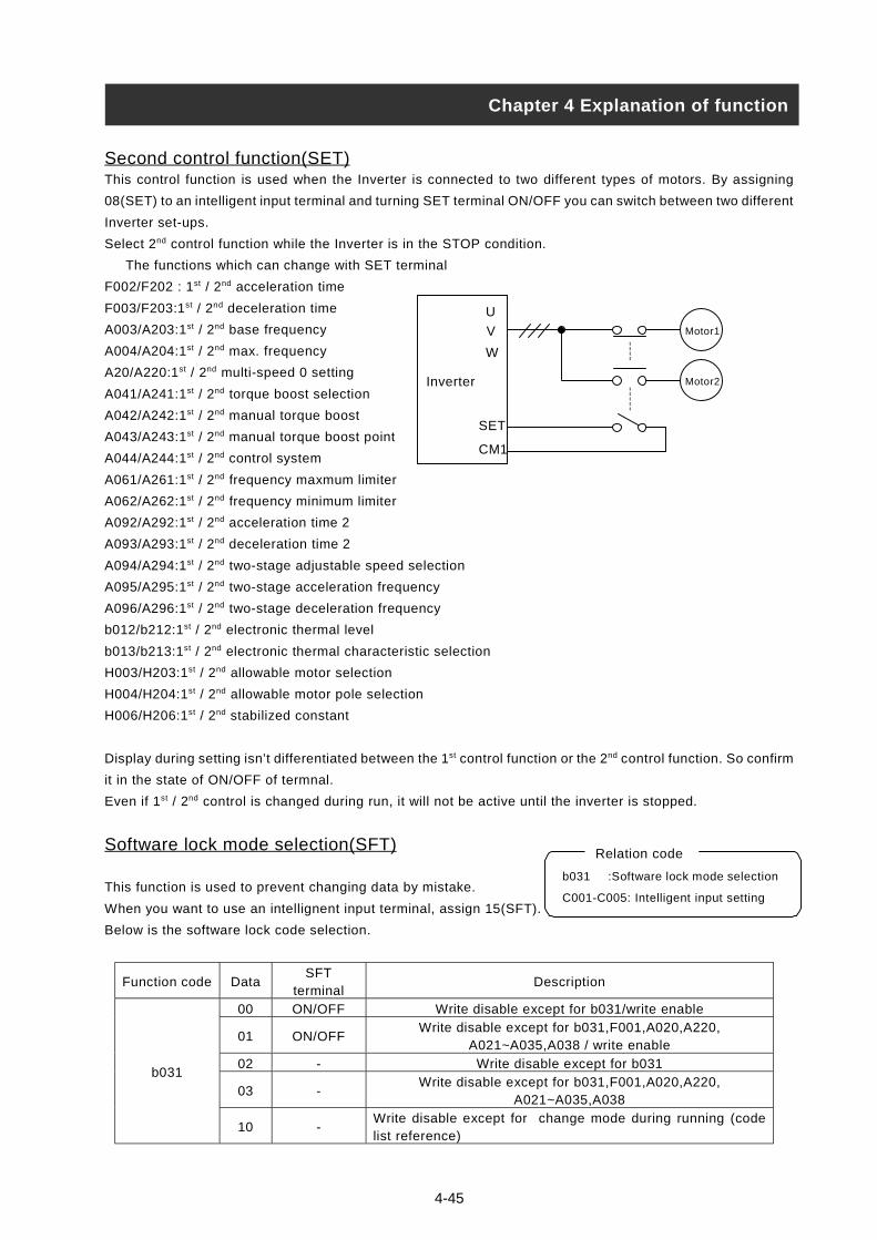
4-45
Second control function(SET)This control function is used when the Inverter is connected to two different types of motors. By assigning
08(SET) to an intelligent input terminal and turning SET terminal ON/OFF you can switch between two different
Inverter set-ups.
Select 2nd control function while the Inverter is in the STOP condition.
The functions which can change with SET terminal
F002/F202 : 1st / 2nd acceleration time
F003/F203:1st / 2nd deceleration time
A003/A203:1st / 2nd base frequency
A004/A204:1st / 2nd max. frequency
A20/A220:1st / 2nd multi-speed 0 setting
A041/A241:1st / 2nd torque boost selection
A042/A242:1st / 2nd manual torque boost
A043/A243:1st / 2nd manual torque boost point
A044/A244:1st / 2nd control system
A061/A261:1st / 2nd frequency maxmum limiter
A062/A262:1st / 2nd frequency minimum limiter
A092/A292:1st / 2nd acceleration time 2
A093/A293:1st / 2nd deceleration time 2
A094/A294:1st / 2nd two-stage adjustable speed selection
A095/A295:1st / 2nd two-stage acceleration frequency
A096/A296:1st / 2nd two-stage deceleration frequency
b012/b212:1st / 2nd electronic thermal level
b013/b213:1st / 2nd electronic thermal characteristic selection
H003/H203:1st / 2nd allowable motor selection
H004/H204:1st / 2nd allowable motor pole selection
H006/H206:1st / 2nd stabilized constant
Display during setting isn’t differentiated between the 1st control function or the 2nd control function. So confirm
it in the state of ON/OFF of termnal.
Even if 1st / 2nd control is changed during run, it will not be active until the inverter is stopped.
Software lock mode selection(SFT)
This function is used to prevent changing data by mistake.
When you want to use an intellignent input terminal, assign 15(SFT).
Below is the software lock code selection.
Function code DataSFT
terminalDescription
00 ON/OFF Write disable except for b031/write enable
01 ON/OFFWrite disable except for b031,F001,A020,A220,
A021~A035,A038 / write enable
02 - Write disable except for b031
03 -Write disable except for b031,F001,A020,A220,
A021~A035,A038
b031
10 -Write disable except for change mode during running (codelist reference)
Chapter 4 Explanation of function
Motor1
Motor2Inverter
U
V
W
SET
CM1
b031 :Software lock mode selection
C001-C005: Intelligent input setting
Relation code
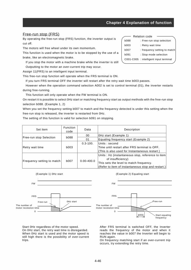
4-46
Free-run stop (FRS)By operating the free-run stop (FRS) function, the inverter output is
cut off.
The motors will free wheel under its own momentum.
This function is used when the motor is to be stopped by the use of a
brake, like an electromagnetic brake.
If you stop the motor with a machine brake while the inverter is still
Outputting to the motor an over-current trip may occur.
Assign 11(FRS) to an intelligent input terminal.
This free-run stop function will operate when the FRS terminal is ON.
If you turn FRS terminal OFF the inverter will restart after the retry wait time b003 passes.
However when the operation command selection A002 is set to control terminal (01), the inverter restarts
during free-running.
This function will only operate when the FW terminal is ON.
On restart it is possible to select 0Hz start or matching frequency start as output methods with the free-run stop
selection b088. (Example 1, 2)
When you set the frequency setting b007 to match and the frequency detected is under this setting when the
free-run stop is released, the inverter is restarted from 0Hz.
The setting of this function is valid for selection b091 on stopping.
Set itemFunction
codeData Description
00 0Hz start (Example 1)Free-run stop Selection b088
01 Equaling frequency start (Example 2)
Retry wait time b0030.3-100. Units : second
Time until restart after FRS terminal is OFF.(This is also used for Instantaneous restart.)
Frequency setting to match b007 0.00-400.0
Units : Hz (instantaneous stop, reference to item of insufficiency)This sets the level to match frequency.(Refer to item of instantaneous stop and restart.)
Chapter 4 Explanation of function
b088 : Free-run stop selection
b003 : Retry wait time
b007 : frequency setting to match
b091 : Stop mode selection
C001-C005 : intelligent input terminal
Relation code
FW
FRS
The number ofmotor revolution time
0
Free-run 0Hz start
(Example 1) 0Hz start
FW
FRS
The number ofmotor revolution time
0
Free-run
Start equalingfrequency
(Example 2) Equaling start
b003
Start 0Hz regardless of the motor speed.On 0Hz start, the retry wait time is disregarded.When 0Hz start is used and the motor speed isstill high there is the possibility of over-currenttrips.
After FRS terminal is switched OFF, the Inverterreads the frequency of the motor and when itreaches the value in b007 the Inverter will begin toRUN again.On frequency matching start if an over-current tripoccurs, try extending the retry time.

Commercial power source switching(CS) This function is used for systems with an excessive amount of starting
torque requirements. The motor would be started direct-on-line and then
when the motor had started the inverter would take over. This function
is comonly used to reduce the costing of the inverter. For example, a system may
require 55kW to start but only 15kW to run at constant speed. Therefore, a 15kW rated inverter would be
sufficient when using the commerical power source switching. Assign 14(CS) to an intelligent input terminal.
Using the example below. When the motor has been started direct-on-line, Mg2 is switched OFF and Mg3 is
switched on. With the Forward command to the inverter already on the CS terminal is switched on and Mg1 is
closed. The Inverter will then read the motor RPM and when the CS terminal is switched OFF the retry wait
time (b003) is started.
Once the wait time has elapsed the inverter will then start and match the frequency which is set (b007).
When the Earth Leakage Breaker (ELB) trips on ground fault, the commercial circuit will not operate. When a
backup is required, take the supply from the commercial circuit ELBC.
For FWY, RVY, CSY, use control relays. The sequence above is reference to the circuit and timing diagram
below.
If an over-current trip occurs when frequency matching, extend the retry wait time (b003).
When the power is supplied to the inverter, also it is possible to activate retry operation too. In this case,
follwing CS terminal is out of necessary. For more information, refer to Reset(RS).
Connection figure example and timing on commercial power source switching
INV commercial power source switching commercial power source INV switching
b003 : retry waiting time
b007 : frequency setting to
match
C001-C005 : Intelligent input terminal
Relation code
Chapter 4 Explanation of function
Mg2
RST
UVW
OL
FW
RV
CS
CM1
AL1
AL2
AL0
THRYMg1 Mg3ELBCNFB
FWY
RVY
CSY
H
Motor
Mg1
Mg2
Mg3
FW
ON
ON
ON
ON
Normally set for 0.5-1 seconds
Interlock time of Mg2 andMg3
OFF
ON
ON
ON
ON
Inverter
output frequenc
CS
Mg1
Mg3
FW
Mg2
ON
20msover
b003 retry waiting time
Inverter output frequency
CS
yOperation
4-47
Frequency matching andoperation
Operation

Reset (RS)This function resets the inverter when a protective trip has occurred.
The method of reset is to either push the STOP/RESET key on the
digital operator or to switch the RS terminal ON.
To reset the inverter with the control terminal, assign 18(RS) to an
intelligent input terminal.
Reset frequency matching selection C103 selects whether the inverter restarts
at 0Hz or the inverter matches the output frequency after the reset operation is complete.
Reset selection C102 selects when the alarm signal is cancelled and whether it is valid or invalid in normal
operation.
The RS terminal is valid only when the contact is set to NO.
Set itemFunction
codeData Description
Retry waiting time b003 0.3-100.
Units : seconds(Reference to items of instantaneous power failureor under-voltage)After reset, time until restart is tried.
Frequency setting to match b007 0.00-400.0Units : Hz(Reference to items of instantaneous stop/under-voltage)
00On ON signal, trip cancel (Example 1)On normal, this is valid (output cuts off).
01On OFF signal, trip cancel (Example 2)On normal, valid (output cuts off)
Reset selection C102
02On ON signal, trip cancel (Example 1)On normal, this is invalid. (only trip cancel)
00 0Hz startReset frequency matchingselection
C10301 Frequency matching start. (Example 3)
Chapter 4 Explanation of function
b003 : Retry waiting time
b007 : Frequency setting to match
C102 : Reset selection
C103 : Reset frequency matching
selection
Relation code
RS
Alarm
(Example 1)
RS
Alarm
(Example 2)
(Example 3) When 01 (frequency matching) is selected with reset frequency matching selection C103,
it is also possible to operate frequency start on power ON again. And retry waiting time is
disregarded at the time of the setting C103:00 (0Hz start).
4-48
Number of motor
revolution time
Power supply
FW
Free-run Frequency matching
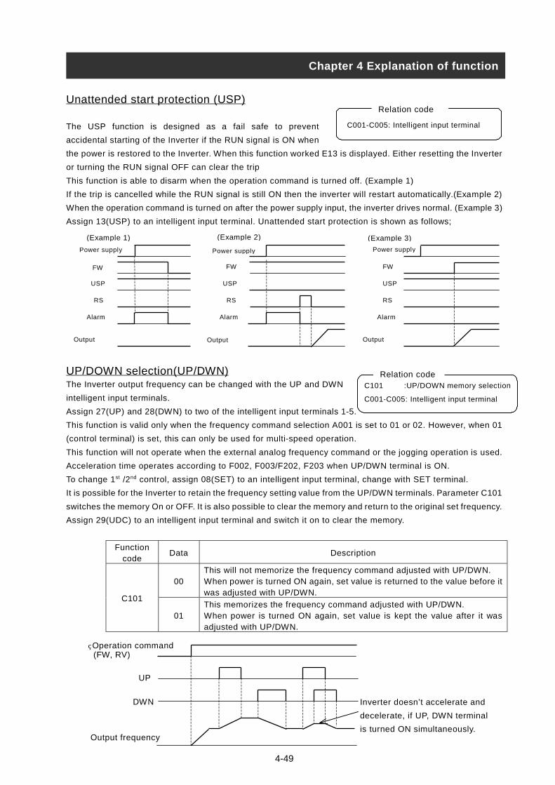
4-49
C001-C005: Intelligent input terminal
Relation codeUnattended start protection (USP)
The USP function is designed as a fail safe to prevent
accidental starting of the Inverter if the RUN signal is ON when
the power is restored to the Inverter. When this function worked E13 is displayed. Either resetting the Inverter
or turning the RUN signal OFF can clear the trip
This function is able to disarm when the operation command is turned off. (Example 1)
If the trip is cancelled while the RUN signal is still ON then the inverter will restart automatically.(Example 2)
When the operation command is turned on after the power supply input, the inverter drives normal. (Example 3)
Assign 13(USP) to an intelligent input terminal. Unattended start protection is shown as follows;
UP/DOWN selection(UP/DWN)The Inverter output frequency can be changed with the UP and DWN
intelligent input terminals.
Assign 27(UP) and 28(DWN) to two of the intelligent input terminals 1-5.
This function is valid only when the frequency command selection A001 is set to 01 or 02. However, when 01
(control terminal) is set, this can only be used for multi-speed operation.
This function will not operate when the external analog frequency command or the jogging operation is used.
Acceleration time operates according to F002, F003/F202, F203 when UP/DWN terminal is ON.
To change 1st /2nd control, assign 08(SET) to an intelligent input terminal, change with SET terminal.
It is possible for the Inverter to retain the frequency setting value from the UP/DWN terminals. Parameter C101
switches the memory On or OFF. It is also possible to clear the memory and return to the original set frequency.
Assign 29(UDC) to an intelligent input terminal and switch it on to clear the memory.
Functioncode
Data Description
00This will not memorize the frequency command adjusted with UP/DWN.When power is turned ON again, set value is returned to the value before itwas adjusted with UP/DWN.
C101
01This memorizes the frequency command adjusted with UP/DWN.When power is turned ON again, set value is kept the value after it wasadjusted with UP/DWN.
Chapter 4 Explanation of function
C101 :UP/DOWN memory selection
C001-C005: Intelligent input terminal
Relation code
Power supply
FW
USP
RS
Alarm
Output
(Example 1)
Power supply
FW
USP
RS
Alarm
(Example 3)
Output
Output frequency
Operation command (FW, RV)
UP
DWN Inverter doesn’t accelerate and
decelerate, if UP, DWN terminal
is turned ON simultaneously.
Output
Power supply
FW
USP
RS
Alarm
(Example 2)

4-50
External trip (EXT)This function can be used to force the Inverter into a trip situation which
is switched by an external input, i.e. PLC or relay contact.
When the EXT terminal is switched ON, the inverter trips on an E12 error and the outputis switched OFF.
Assign 12(EXT) to an intelligent input terminal.
The trip will not be canceled when the terminal is turned OFF.
To cancel the trip, the reset signal must be applied or the Inverter switched OFF and ON again at the supply.
3 Wire input function(STA, STP, F/R)This function is used when a momentary push start/stop control is
required.
Set the operation command selection A002 to control terminal (01).
Assign 20 (STA), 21 (STP) and 22 (F/R) to three of the intelligent input terminals, and the operation becomes
possible as follows. When the terminal is assigned STP terminal, FW terminal and also RV terminal become
invalid. If all three inputs are not assigned this function will not operate.
The FW terminal and RV terminal become redundant when the 3 wire control is assigned to the intelligent input
terminals. Output from the 3 wire control terminal is as follows;
STA ON OFF
OFFON
Forward
Reverse
STP
F/R
Output frequency
Chapter 4 Explanation of function
C001-C005: Intelligent input terminal
Relation code
Free-run
Operation commandFW,RV
EXT terminal
Number of Motorrevolution time
RS terminal
Alarm output terminal
C001-C005: Intelligent input terminal
Relation code
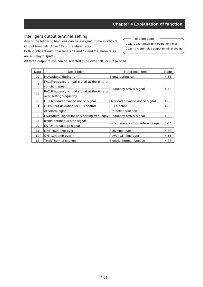
4-51
Intelligent output terminal settingAny of the following functions can be assigned to the intelligent
Output terminals (11 or 12) or the alarm relay.
Both intelligent output terminals 11 and 12 and the alarm relay
are all relay outputs.
All three output relays can be selected to be either NO or NC (a or b).
Data Description Reference item Page
00 RUN:Signal during run Signal during run 4-53
01FA1:Frequency arrival signal at the time of
constant speed
02FA2:Frequency arrival signal at the time of
over setting frequency
Frequency arrival signal 4-53
03 OL:Overload advance notice signal Overload advance notice signal 4-38
04 OD:output deviation for PID control PID function 4-30
05 AL:Alarm signal Protection function -
06 FA3:Arrival signal for only setting frequency Frequency arrival signal 4-53
08 IP:Instantaneous stop signal
09 UV:Under voltage signalInstantaneous stop/under-voltage 4-34
11 RNT:RUN time over RUN time over 4-55
12 ONT:ON time over Power ON time over 4-55
13 THM:Thermal caution Electric thermal function 4-38
Chapter 4 Explanation of function
C021-C022 : Intelligent output terminal
C026 : Alarm relay output terminal setting
Relation code
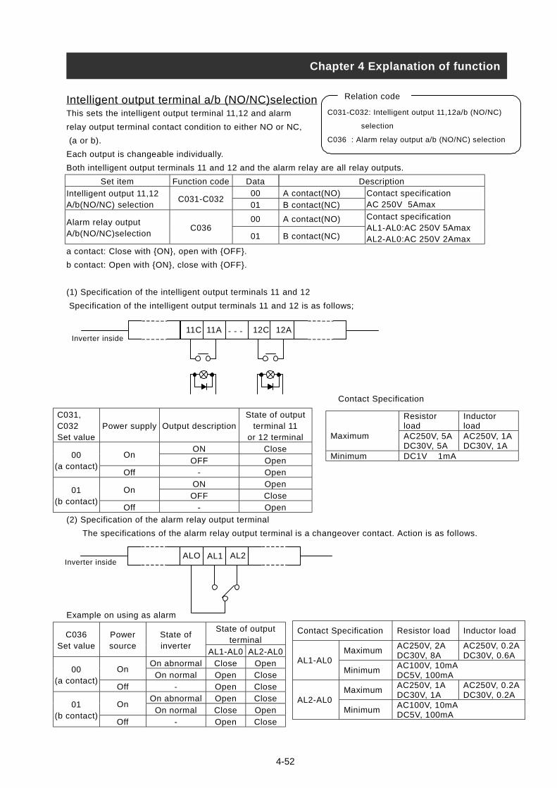
4-52
Intelligent output terminal a/b (NO/NC)selectionThis sets the intelligent output terminal 11,12 and alarm
relay output terminal contact condition to either NO or NC,
(a or b).
Each output is changeable individually.
Both intelligent output terminals 11 and 12 and the alarm relay are all relay outputs.
Set item Function code Data Description
00 A contact(NO)Intelligent output 11,12A/b(NO/NC) selection
C031-C03201 B contact(NC)
Contact specificationAC 250V 5Amax
00 A contact(NO)Alarm relay outputA/b(NO/NC)selection
C03601 B contact(NC)
Contact specificationAL1-AL0:AC 250V 5AmaxAL2-AL0:AC 250V 2Amax
a contact: Close with {ON}, open with {OFF}.
b contact: Open with {ON}, close with {OFF}.
(1) Specification of the intelligent output terminals 11 and 12
Specification of the intelligent output terminals 11 and 12 is as follows;
C031, C032Set value
Power supply Output descriptionState of output
terminal 11or 12 terminal
ON CloseOn
OFF Open00
(a contact)Off - Open
ON OpenOn
OFF Close01
(b contact)Off - Open
(2) Specification of the alarm relay output terminal
The specifications of the alarm relay output terminal is a changeover contact. Action is as follows.
Example on using as alarm
State of outputterminal
C036Set value
Powersource
State ofinverter
AL1-AL0 AL2-AL0
On abnormal Close OpenOn
On normal Open Close00
(a contact)Off - Open Close
On abnormal Open CloseOn
On normal Close Open01
(b contact)Off - Open Close
C031-C032: Intelligent output 11,12a/b (NO/NC)
selection
C036 : Alarm relay output a/b (NO/NC) selection
Relation code
Chapter 4 Explanation of function
Inverter inside11C 11A 12C 12A- - -
ALO AL1 AL2Inverter inside
Resistorload
Inductorload
Maximum AC250V, 5ADC30V, 5A
AC250V, 1ADC30V, 1A
Minimum DC1V 1mA
Contact Specification Resistor load Inductor load
MaximumAC250V, 2ADC30V, 8A
AC250V, 0.2ADC30V, 0.6A
AL1-AL0Minimum
AC100V, 10mADC5V, 100mA
MaximumAC250V, 1ADC30V, 1A
AC250V, 0.2ADC30V, 0.2A
AL2-AL0Minimum
AC100V, 10mADC5V, 100mA
Contact Specification

4-53
Signal during run (RUN)This function is to provide an output signal when the Inverter is in a
running condition.
Assign 00(RUN: signal during run) to an intelligent output terminal
11,12 or the alarm relay output terminal.
The signal is still outputted when the dc braking operates.
The signal is not outputted when the output frequency is 0Hz , and when the status of the inverter is retry.
Operation is as follows;
Frequency arrival signal (FA1, FA2, FA3)When the output frequency arrives at the set frequency, an arrival
signal is outputted.
Assign 01(FA1:constant speed arrival signal), 02(FA2:over setting
frequency) or 06(FA3: only setting frequency) to an intelligent output
terminal 11, 12 or the alarm relay output terminal.
Hysteresis frequency arrival signal is the following.
When ON : ON with (1% of setting frequency – maximum frequency)(Hz)
When OFF: OFF with (2% of setting frequency – maximum frequency)(Hz)
However in to set 06(FA3) case when inverter accelerate.
When ON :(1% of setting frequency – maximum frequency)(Hz)
When OFF: (2% of setting frequency + maximum frequency)(Hz)
When inverter decelerates
When ON : (1% of setting frequency + maximum frequency)(Hz)
When OFF: (2% of setting frequency – maximum frequency)(Hz)
Set item Function code Data (Hz) Description
0.0 Arrival signal at acceleration is OFF.Accelerationarrival frequency
C0420.01-400.0 Arrival signal at acceleration is ON.
0.0 Arrival signal at deceleration is OFF.Decelerationarrival frequency
C0430.01-400.0 Arrival signal at deceleration is ON.
Chapter 4 Explanation of function
C001-C005: Intelligent input terminal
C021,C022: Intelligent output terminal
C026: Alarm relay output
Relation code
C021,C022: Intelligent output terminal
C026 : Alarm relay output
C042 :Acceleration arrival frequency
C043 :Deceleration arrival frequency
Relation code
RUN
Output frequency
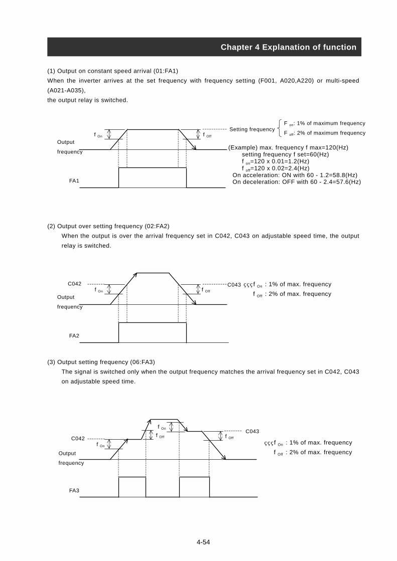
4-54
(1) Output on constant speed arrival (01:FA1)
When the inverter arrives at the set frequency with frequency setting (F001, A020,A220) or multi-speed
(A021-A035),
the output relay is switched.
(2) Output over setting frequency (02:FA2)
When the output is over the arrival frequency set in C04
relay is switched.
(3) Output setting frequency (06:FA3)
The signal is switched only when the output frequency ma
on adjustable speed time.
Chapter 4 Explanation of function
FA1
Output
frequency
f Offf On
FA2
Output
frequency
f Offf On
C042
FA3
Output
frequency
f On
C042
f On
f Off
Setting frequency
2, C043 on adju
tches the arriva
(Example) max.setting freqf on=120 x 0f off=120 x 0
On acceleratioOn deceleratio
f On : 1%
f Off : 2%
C043
f Off
C043
F on: 1% of maximum frequency
F off: 2% of maximum frequency
stable speed time, the output
l frequency set in C042, C043
frequency f max=120(Hz)uency f set=60(Hz).01=1.2(Hz).02=2.4(Hz)n: ON with 60 - 1.2=58.8(Hz)n: OFF with 60 - 2.4=57.6(Hz)
of max. frequency
of max. frequency
f On : 1% of max. frequency
f Off : 2% of max. frequency

4-55
RUN time / power ON time over (RNT/ONT)When the accumulated operation time reaches or is over the
Setting time in b034, RUN time/power ON time over (RNT/ONT)
output is switched.
Function
codeData Description
b034
0.
1. -9999.
1000-6553
Don’t operate.
Set by 10-hour unit.
Set by 100 hours unit. (10000-65530
(1) Run time over (RNT)
Assign 11(RNT) to an intelligent output terminal 11, 12 (C021, C022
(C026).
Set ON time level with b034.
(2) Power ON time over (ONT)
Assign 12(ONT) to an intelligent output terminal 11, 12 (C021, C022)
Set ON time level with b034.
Force operation ope functionThis function is used to operate from the operator forcibly by on/off
of an intelligent terminal when frequency and operation command
is selected other than the operator.
Becoming the operation from the frequency and operation command tha
the signal is off, and becoming the frequency and operation command fro
on when the compulsion operation function is selected by an intelligent i
When changed the operation command while driving, operation comman
at first.
Operation command from each command input the operation command o
driving once again.
Setting item Function cord Setting value
Frequency command selection A001
00
01
02
03
04
05
Po
Te
Op
RS
Op
Op
Operation command selection A002
01
02
03
04
05
Te
Op
RS
Op
Op
Intelligent input selection C001-C005 31 OP
Chapter 4 on of function
b034
C021
C026
d016
d017
A00
A00
C00
Relation code Explanati
hours)
) or the alarm relay output terminal
or the alarm output terminal, (C026).
t was selected by A001 and A002 if
m an operator forcibly if the signal is
nput selection.
d is canceled and become stoppage
nce again as the stoppage at first for
Contents
tentiometer the digital operator has
rminal
erator
485
tion 1
tion 2
rminal
erator
485
tion 1
tion 2
E : Compulsion operation
: Warning time level
,C022: Intelligent output terminal
: Alarm relay output terminal
:Accumulation time monitor during RUN
:Power ON time monitor
Relation code
1: Frequency setting selection
2: Operation command selection
1-C005: Intelligent input terminal
Relation code
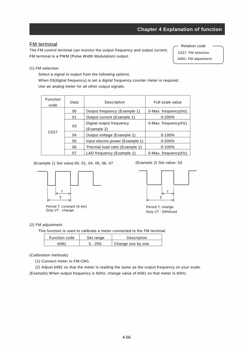
4-56
FM terminalThe FM control terminal can monitor the output frequency and output current.
FM terminal is a PWM (Pulse Width Modulation) output.
(1) FM selection
Select a signal to output from the following options.
When 03(digital frequency) is set a digital frequency counter meter is required.
Use an analog meter for all other output signals.
Function
codeData Description Full scale value
00 Output frequency (Example 1) 0-Max. frequency(Hz)
01 Output current (Example 1) 0-200%
03Digital output frequency
(Example 2)
0-Max. frequency(Hz)
04 Output voltage (Example 1) 0-100%
05 Input electric power (Example 1) 0-200%
06 Thermal load ratio (Example 1) 0-100%
C027
07 LAD frequency (Example 1) 0-Max. frequency(Hz)
(2) FM adjustment
This function is used to calibrate a meter connected t
Function code Set range Des
b081 0. -255. Change on
(Calibration methods)
(1) Connect meter to FM-CM1.
(2) Adjust b081 so that the meter is reading the same a
(Example) When output frequency is 60Hz, change value
Chapter 4 Explanation of function
C027: FM selection
b081: FM adjustment
Relation code
Period T: constant (6.4m)Duty t/T : change
t
T
(Example 1) Set value:00, 01, 04, 05, 06, 07
(Example 2) Set value: 03o the FM terminal.
cription
e by one.
s the output frequency on your scale.
of b081 so that meter is 60Hz.
t
T
Period T: change
Duty t/T : 50%fixed

4-57
AM terminal, AMI terminalThe AM terminal and the AMI terminal can monitor the output frequency or
the output current.
The AM terminal has an analog output of 0-10V.
The AMI terminal has an analog output of 4-20mA.
(1) AM, AMI selection
Select a signal to output from the following options;
Set item Function code Data Contents Full scale value
00 Output frequency 0-Max. frequency(Hz)
01 Output current 0-200%
04 Output voltage 0-100%
05 Input electric power 0-200%
06 Thermal load ratio 0-100%
AM selection/AMI selection
C028/C029
07 LAD frequency 0-Max. frequency(Hz)
(2) AM adjustment, AMI adjustment
This function is used to calibrate a meter connected to the AM and AMI terminal.
Set itemFunction
codeData Description
AM adjustment b080 0. -255.After offset adjustment with C086, adjust according tomemory.
AM offsetAdjustment
C086 0.0-10.0 Units : V
AMI adjustment C087 0. -255.After offset adjustment with C088, adjust according tomemory.
AMI offsetadjustment
C088 0.0-20.0 Units : mA
External thermistor(TH)Temperature protection of the external machine is possible by the use
of a Thermistor fitted to your motor.
Wire the thermistor between control terminals TH and CM1.
Set the following function according to the thermistor specification.
Set itemFunction
codeSet value Contents
00Invalid(No temperature protection by external thermistor)
01Valid normal temperature/factor resistance element(For PTC)
Thermistor selection b098
02 Valid (For NTC)
Thermistor error level b099 0. -9999.Units : OHMSet the resistance value of temperature for tripaccording to thermistor methods.
Thermistor adjustment C085 0.0-1000. Use this as gain adjustment.
Chapter 4 Explanation of function
b080 : AM adjustment
C028 : AM selection
C029 : AMI selection
C086 : AM offset adjustment
C087 : AMI adjustment
C088 : AMI offset adjustment
Relation code
b098: Thermistor selection
b099: Thermistor error level
C085: Thermistor adjustment
Relation code

4-58
Initialization settingIt is possible at any time to reinitialize the Inverter parameters back to there
factory default. The trip history can also be cleared at any time, however, if
problems occur it will be difficult to fault find without the trip history for reference.
Initialization details are as follows;
Set itemFunction
modeData Description
00 This clears only trip history.
01
This only initializes setting value.
Setting value becomes the state on factory
forwarding.
Initialization
selectionb084
02 This clears trip history and initializes setting.
00 Initializing setting for Japan.
01 Initializing setting for EuropeInitial data
selectionb085
02 Initializing setting for America.
(Initialization methods)
After setting the above parameters, initialize as follows;
Chapter 4 Explanation of function
b084: Initialization selection
b085: Initial data selection
Relation code
POW ER
%
A
ALARMRUN
PRGV
Hz
kW
1 2
H I T A C H I
MIN MAX
STR
RUNSTOP/RESET
FUNC
(1) Hold down the FUNC, UP and
DOWN key and then press the STR
key. When the display starts to flash
and rotate release all the keys.
(2) During initializing
Above display is fo
Other displays are
During initializing for Europe.
During initializing of trip history.
During initializing for America.
RUN
PRG
1 2
H I T A C H I
MINRUNSTOP/RESET
FUNC
POW ER
POW ERr Japan.
below.
(3) When “d001” is displayed in the
monitor, initialization is complete.
The display revolves on the left.
%A
ALARM
V
Hz
kW
MAX
STR
%
A
RUN
PRGV
Hz
kW
1 2
H I T A C H I
MIN MAX
STR
RUNSTOP/RESET
FUNC
ALARM
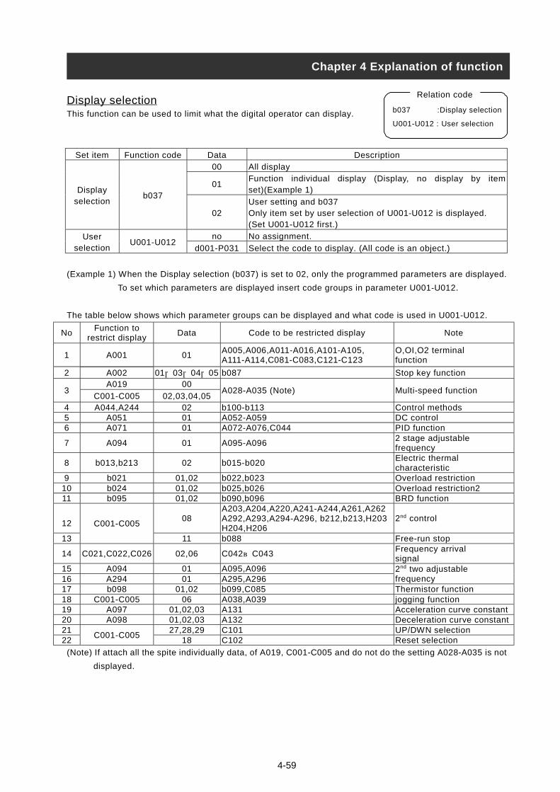
4-59
Display selectionThis function can be used to limit what the digital operator can display.
Set item Function code Data Description
00 All display
01Function individual display (Display, no display by itemset)(Example 1)Display
selectionb037
02User setting and b037Only item set by user selection of U001-U012 is displayed.(Set U001-U012 first.)
no No assignment.Userselection
U001-U012d001-P031 Select the code to display. (All code is an object.)
(Example 1) When the Display selection (b037) is set to 02, only the programmed parameters are displayed.
To set which parameters are displayed insert code groups in parameter U001-U012.
The table below shows which parameter groups can be displayed and what code is used in U001-U012.
NoFunction to
restrict displayData Code to be restricted display Note
1 A001 01A005,A006,A011-A016,A101-A105,A111-A114,C081-C083,C121-C123
O,OI,O2 terminalfunction
2 A002 01,03,04,05 b087 Stop key functionA019 00
3C001-C005 02,03,04,05
A028-A035 (Note) Multi-speed function
4 A044,A244 02 b100-b113 Control methods5 A051 01 A052-A059 DC control6 A071 01 A072-A076,C044 PID function
7 A094 01 A095-A0962 stage adjustablefrequency
8 b013,b213 02 b015-b020Electric thermalcharacteristic
9 b021 01,02 b022,b023 Overload restriction10 b024 01,02 b025,b026 Overload restriction211 b095 01,02 b090,b096 BRD function
1208
A203,A204,A220,A241-A244,A261,A262A292,A293,A294-A296, b212,b213,H203H204,H206
2nd control
13
C001-C005
11 b088 Free-run stop
14 C021,C022,C026 02,06 C042~C043Frequency arrivalsignal
15 A094 01 A095,A09616 A294 01 A295,A296
2nd two adjustablefrequency
17 b098 01,02 b099,C085 Thermistor function18 C001-C005 06 A038,A039 jogging function19 A097 01,02,03 A131 Acceleration curve constant20 A098 01,02,03 A132 Deceleration curve constant21 27,28,29 C101 UP/DWN selection22
C001-C00518 C102 Reset selection
(Note) If attach all the spite individually data, of A019, C001-C005 and do not do the setting A028-A035 is not
displayed.
Chapter 4 Explanation of function
b037 :Display selection
U001-U012 : User selection
Relation code

4-60
Stabilized factor When the motor is hunting or unstable, this function can be adjusted to
help stabilize the motor.
When the motor is unstable, check the allowable motor selection (H003/H203) and motor pole selection
(H004/H204) with your motor. If their code data is different from your motor specification, set the right data.
When R1 of usage motor is less than R1 of regular motor, raise the set value of H006/H206 gradually.
When you operate greater motor than rated capacity of inverter, lower the set value of H006/H206.
The following two functions can also assist to reduce hunting or rattling of a motor.
(1) Lower the carrier frequency (b083).
(2) Lower the output voltage gain (A045).
Set itemFunction
codeData Description
Output gain A045 20. -100.Units :%Lower this when hunting occurs.
0.5-12.0(11 to 75kW)Carrier
frequencyb083
0.5-8.0(90 to 132kW)
Units :kHzLower this when hunting occurs.
Stabilizedfactor
H006/H206 0. -255. Raise or lower when hunting occurs.
Operation selection on option errorWhen an add-in option is the cause of a protective trip this
function can be used to switch the trip facility off and allow
the Inverter to carry on in it’s operation.
Set itemFunction
codeData Description
00 TRP: inverter trip and output alarm when option error occurs.Operation selectionon optional error
P001/P00201
RUN: inverter ignores this and continues operation whenoption error occurs.
Motor constantSet each constant according to the motor you use.
In case of using several motors in parallel, set the constant
values that are closest to the total capacity of the belonging motor.
Reduced torque or instability may occur while using auto torque boost function if these settings are incorrect.
P001: Option1 operation selection on error
P002: Option 2 operation selection on error
Relation code
Chapter 4 Explanation of function
H006/H206: 1st /2nd stabilized factor
Relation code
H003/H203: 1st /2nd allowable motor selection
H004/H204: 1st /2nd motor pole selection
Relation code

Communication function Serial communication is possible from the Inverter to any external
equipment using RS485 protocol. This function is built-in as
standard and is controlled by the TM2 control terminals.
(1) Communication specification
<RS485 port specification and connection>
Use TM2 of controls terminal PCB for RS485 communication function.
Item Specification Notes
Transmission speed 2400/4800/9600/19200 bps Selection withoperator
Communication methods Half duplex communication methodsSynchronizing methods Direct current transmissionTransmission code ASCII codeTransmission methods Transmission from lower bitCommunication interface RS485Data bit 7/8 bit Selection with
OperatorParity No parity/even/odd Selection with
OperatorStop bit 1/2 bit Selection with
OperatorStart methods One-way start form by command of host sideWaiting time 0-1000[ms] Setting with
operatorConnect form 1:N (N = Maximum 32) Station number is
selected withoperator.
Error check Overrun / Fleming / BCC / Vertical / Horizontal parity
Chapter 4 Explanation of function
Abbreviationname
Description
S PTransmission andreception + side
S NTransmission andreception - side
R PTerminal resistancevalid terminal
S NTerminal resistancevalid terminal
Relation code
A001: Frequency selection
A002: Operation command selection
C070: Data command
C071: Communication transmission speed
C072: Communication code
C073: Communication bit
C074: Communication parity
C075: Communication stop bit
C078: Communication waiting time
Control terminal
PCB
Control terminal
4-61
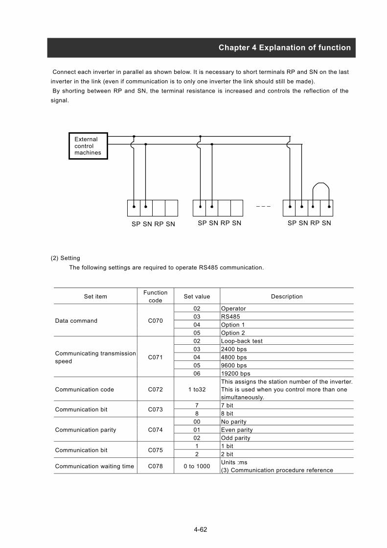
Connect each inverter in parallel as shown below. It is necessary to short terminals RP and SN on the last
inverter in the link (even if communication is to only one inverter the link should still be made).
By shorting between RP and SN, the terminal resistance is increased and controls the reflection of the
signal.
(2) Setting
The following settings are required to operate RS485 communication.
SP SN RP SN SP SN RP SN
Externalcontrolmachines
_ _ _
SP SN RP SN
Data com
Communspeed
Commun
Commun
Commun
Commun
Commun
Chapter 4 Explanation of function
Set itemFunction
codeSet value Description
02 Operator
03 RS485
04 Option 1mand C070
05 Option 2
02 Loop-back test
03 2400 bps
04 4800 bps
05 9600 bps
icating transmissionC071
06 19200 bps
ication code C072 1 to32This assigns the station number of the inverter.This is used when you control more than onesimultaneously.
7 7 bitication bit C073
8 8 bit
00 No parity
01 Even parityication parity C074
02 Odd parity
1 1 bitication bit C075
2 2 bit
ication waiting time C078 0 to 1000Units :ms(3) Communication procedure reference
4-62
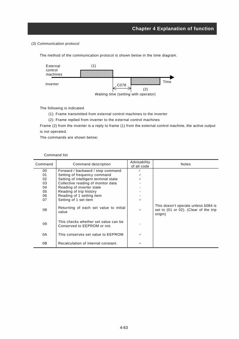
(3) Communication protocol
The method of the communication protocol is shown below in the time diagram.
The following is indicated.
(1): Frame transmitted from external control machines to the inverter
(2): Frame replied from inverter to the external control machines
Frame (2) from the inverter is a reply to frame (1) from the external control machine, the active output
is not operated.
The commands are shown below;
Command list
Chapter 4 Explanation of function
Waiting time (setting with operator)
TimeInverter
Externalcontrolmachines
(2)
(1)
C078
Command Command descriptionAdvisabilityof all code
Notes
00 Forward / backward / stop command
01 Setting of frequency command
02 Setting of intelligent terminal state
03 Collective reading of monitor data -04 Reading of inverter state -05 Reading of trip history -06 Reading of 1 setting item -07 Setting of 1 set item
08Returning of each set value to initialvalue
This doesn’t operate unless b084 isset to (01 or 02). (Clear of the triporigin)
09This checks whether set value can beConserved to EEPROM or not.
-
0A This conserves set value to EEPROM
0B Recalculation of internal constant.
4-63

4-64
Explanation of each command is the following.
(i) 00 command : This controls the forward, backward and stop command. (Set up A002 in 03 in the case that
this command is used.)
• Transmission frame
Frame format
Explanation Data size Value
STX Control code (Start of TeXt) 1 byte STX (0x02)
Code Station number of inverter 2 byte 01-32, and FF(broadcast)
Command Transmission command 2 byte 00
Data Transmission data 1 byte (Note 1) Reference
BCC Bloc check code 2 byte Exclusive OR of Code, Command and Data
CRControl code(Carriage Return)
1 byte CR (0x0D)
(Note 1)
(Example) When you transmit forward command to code 01
(STX)|01|00|1|(BCC)|(CR) 02|30 31|30 30|31|33 30|0D
Reply frame
On normal reply : (4) - (i) reference
On abnormal reply : (4) - (ii) reference
(ii) 01 command: This is to set frequency command. (Set up A001 in 03 in the case that this command is
used.)
• Transmission frame
Frame format
Explanation Data size Value
STX Control code (Start of TeXt) 1 byte STX (0x02)
Code Station number of inverter 2 byte 01-32, and FF (broadcast)
Command Transmission command 2 byte 01
DataTransmission data ( tenth ASCII code)
6 byte (Note 2) Reference
BCC Block check code 2 byte Exclusive OR of Code, Command and Data
CRControl code(Carriage Return)
1 byte CR (0x0D)
(Note 2) When you set code 01 for 5Hz
(STX)|01|01|000500|(BCC)|(CR)
02|30 31|30 31|30 30 30 35 30 30|30 35|0D
(Note) The data is 100 times as big as set value.
(Example) 5(Hz) 500 000500 30 30 30 35 30 30
Reply frame
On normal reply : (4) - (i) Reference
On abnormal reply : (4) - (ii) reference
STX Code Command Data BCC CR
Data Description Note
0 Stop command
1 Forward command
2 Reverse command
STX Code Command Data BCC CR
Chapter 4 Explanation of functionChapter 4 Explanation of function
ASCIIconverter
ASCII
ASCII conversion
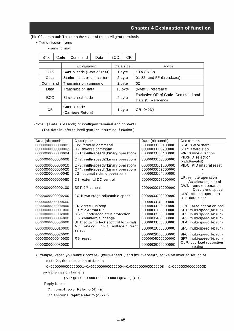
(iii) 02 command: This sets the state of the intelligent terminals.
• Transmission frame
Frame format
Explanation Data size Value
STX Control code (Start of TeXt) 1 byte STX (0x02)
Code Station number of inverter 2 byte 01-32, and FF (broadcast)
Command Transmission command 2 byte 02
Data Transmission data 16 byte (Note 3) reference
BCC Block check code 2 byteExclusive OR of Code, Command and
Data (5) Reference
CRControl code
(Carriage Return)1 byte CR (0x0D)
(Note 3) Data (sixteenth) of intelligent terminal and contents
(The details refer to intelligent input terminal function.)
STX Code Command Data BCC CR
Chapter 4 Explanation of function
(Example) When you make (forward), (multi-speed1) and (multi-speed2) active on inverter setting of
Data (sixteenth) Description Data (sixteenth) Description0000000000000001 FW: forward command 0000000000100000 STA: 3 wire start0000000000000002 RV: reverse command 0000000000200000 STP: 3 wire stop0000000000000004 CF1: multi-speed1(binary operation) 0000000000400000 F/R: 3 wire direction
0000000000000008 CF2: multi-speed2(binary operation) 0000000000800000PID:PID selection(valid/invalid)
0000000000000010 CF3: multi-speed3(binary operation) 0000000001000000 PIDC: PID integral reset0000000000000020 CF4: multi-speed4(binary operation) 0000000002000000 -0000000000000040 JG: jogging(inching operation) 0000000004000000 -
0000000000000080 DB: external DC control 0000000008000000UP: remote operation Accelerating speed
0000000000000100 SET: 2nd control 0000000010000000DWN: remote operation Decelerate speed
0000000000000200 2CH: two stage adjustable speed 0000000020000000UDC: remote operation data clear
0000000000000400 - 0000000040000000 -0000000000000800 FRS: free-run stop 0000000080000000 OPE:Force operation ope0000000000001000 EXP: external trip 0000000100000000 SF1: multi-speed(bit run)0000000000002000 USP: unattended start protection 0000000200000000 SF2: multi-speed(bit run)0000000000004000 CS: commercial change 0000000400000000 SF3: multi-speed(bit run)0000000000008000 SFT: software lock (control terminal) 0000000800000000 SF4: multi-speed(bit run)
0000000000010000AT: analog input voltage/currentselect
0000001000000000 SF5: multi-speed(bit run)
0000000000020000 - 0000002000000000 SF6: multi-speed(bit run)0000000000040000 RS: reset 0000004000000000 SF7: multi-speed(bit run)
0000000000080000 - 0000008000000000OLR: overload restriction setting
4-65
code 01, the calculation of data is
0x0000000000000001+0x0000000000000004+0x0000000000000008 = 0x000000000000000D
so transmission frame is
(STX)|01|02|000000000000000D|(BCC)|(CR)
Reply frame
On normal reply: Refer to (4) - (i)
On abnormal reply: Refer to (4) - (ii)
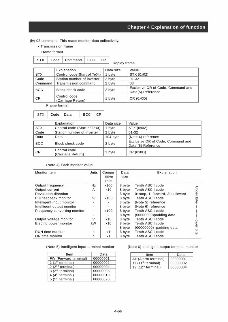
(iv) 03 command: This reads monitor data collectively.
• Transmission frame
Frame format
Replay frame
Frame format
(Note 4) Each monitor value
(Note 5) Intelligent input terminal monitor (Note 6) Intelligent output terminal monitor
STX Code Command BCC CR
Explanation Data size ValueSTX Control code(Start of TeXt) 1 byte STX (0x02)Code Station number of inverter 2 byte 01-32Command Transmission command 2 byte 03
BCC Block check code 2 byteExclusive OR of Code, Command andData(5) Reference
CRControl code(Carriage Return)
1 byte CR (0x0D)
Explanation Data size ValueSTX Control code (Start of TeXt) 1 byte STX (0x02)Code Station number of inverter 2 byte 01-32Data Data 104 byte (Note 4) reference
BCC Block check code 2 byteExclusive OR of Code, Command andData (5) Reference
CRControl code(Carriage Return)
1 byte CR (0x0D)
STX Code Data BCC CR
Monitor item Units Compe-titiverate
Datasize
Explanation
Output frequency Hz x100 8 byte Tenth ASCII codeOutput current A x10 8 byte Tenth ASCII codeRevolution direction - - 8 byte 0: stop, 1: forward, 2:backwardPID feedback monitor % x100 8 byte Tenth ASCII codeIntelligent input monitor - - 8 byte (Note 5) referenceIntelligent output monitor - - 8 byte (Note 6) referenceFrequency converting monitor
---
x100-
8 byte8 byte
Tenth ASCII code(00000000)padding data
Output voltage monitor V x10 8 byte Tenth ASCII codeElectric power monitor kW x10 8 byte Tenth ASCII code
- - - 8 byte (00000000) padding dataRUN time monitor h x1 8 byte Tenth ASCII codeON time monitor h x1 8 byte Tenth ASCII code
Up
pe
r bite
------------low
er b
ite
FW (For1 (1st ter2 (2nd ter3 (3rd ter4 (4th ter5 (5th ter
AL (Ala11 (11th
12 (12t
Chapter 4 Explanation of function
Item Dataward terminal) 00000001minal) 00000002minal) 00000004minal) 00000008minal) 00000010minal) 00000020
4-66
Item Datarm terminal) 00000001 terminal) 00000002
h terminal) 00000004
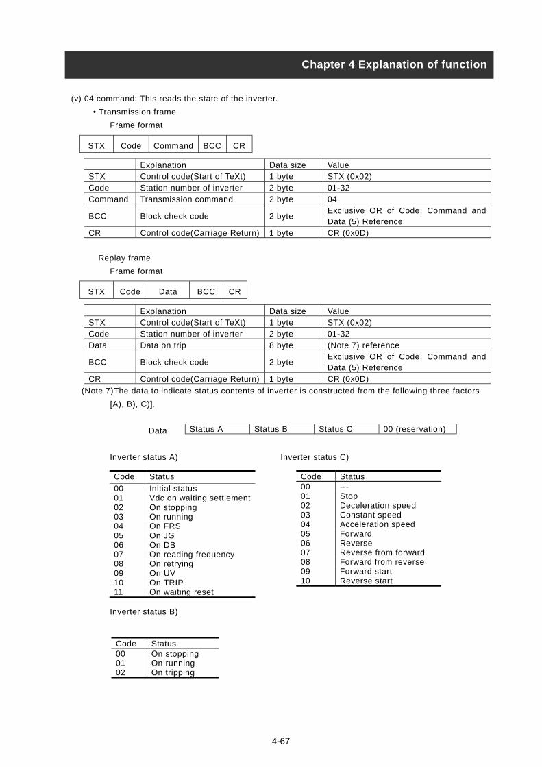
(v) 04 command: This reads the state of the inverter.
• Transmission frame
Frame format
Explanation Data size Value
STX Control code(Start of TeXt) 1 byte STX (0x02)
Code Station number of inverter 2 byte 01-32
Command Transmission command 2 byte 04
BCC Block check code 2 byteExclusive OR of Code, Command andData (5) Reference
CR Control code(Carriage Return) 1 byte CR (0x0D)
Replay frame
Frame format
Explanation Data size Value
STX Control code(Start of TeXt) 1 byte STX (0x02)
Code Station number of inverter 2 byte 01-32
Data Data on trip 8 byte (Note 7) reference
BCC Block check code 2 byteExclusive OR of Code, Command andData (5) Reference
CR Control code(Carriage Return) 1 byte CR (0x0D)
(Note 7)The data to indicate status contents of inverter is constructed from the following three factors
[A), B), C)].
Data
Inverter status A) Inverter status C)
STX Code Command BCC CR
STX Code Data BCC CR
Chapter 4 Explanation of function
Status A Status B Status C 00 (reservation)
Code Status
00 Initial status01 Vdc on waiting settlement02 On stopping03 On running04 On FRS05 On JG06 On DB07 On reading frequency08 On retrying09 On UV10 On TRIP11 On waiting reset
Inverter status B)
Code Status00 On stopping01 On running02 On tripping
4-67
Code Status00 ---01 Stop02 Deceleration speed03 Constant speed04 Acceleration speed05 Forward06 Reverse07 Reverse from forward08 Forward from reverse09 Forward start10 Reverse start

4-68
(vi) 05 command: This reads trip history data.
• Transmission frame
Frame format
Explanation Data size Value
STX Control code(Start of TeXt) 1 byte STX (0x02)
Cord Station number of inverter 2 byte 01-32
Command Transmission command 2 byte 05
BCC Block check code 2 byteExclusive OR of Code, Command and
Data (5) Reference
CR Control code(Carriage Return) 1 byte CR (0x0D)
Replay frame
Frame format:
Explanation Data size Value
STX Control code(Start of TeXt) 1 byte STX (0x02)
Code Station number of inverter 2 byte 01-32
Data Each monitor data on trip 440 byte (Note 8) reference
BCC Block check code 2 byteExclusive OR of Code, Command and Data
(5) Reference
CR Control code(Carriage Return) 1 byte CR (0x0D)
Note 8) The monitor data (trip history) on trip memorizes the last six errors with an accumulated count
number (8byte).
_ _ _
STX Code Command BCC CR
STX Code Data BCC CR
Accumulated
count numberTrip history 1
Trip history 6
Monitor item Units Magnification
Datasize
Notes
Trip factor - - 8byte Cord displayInverter status A) - - 8byteInverter status B) - - 8byteInverter status C) - - 8byte
04 command Note 7 reference
Output frequency Hz x10 8byte Tenth ASCII codeOutput current A x10 8byte Tenth ASCII codeCurrent voltage V x10 8byte Tenth ASCII codeAccumulated RUN time hour x 1 8byte Tenth ASCII codePower source ON time hour x1 8byte Tenth ASCII code
Up
pe
r Lo
we
r
Chapter 4 Explanation of function
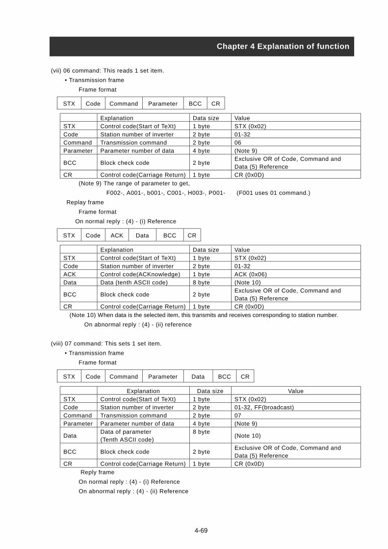
4-69
(vii) 06 command: This reads 1 set item.
• Transmission frame
Frame format
Explanation Data size Value
STX Control code(Start of TeXt) 1 byte STX (0x02)
Code Station number of inverter 2 byte 01-32
Command Transmission command 2 byte 06
Parameter Parameter number of data 4 byte (Note 9)
BCC Block check code 2 byteExclusive OR of Code, Command andData (5) Reference
CR Control code(Carriage Return) 1 byte CR (0x0D)
(Note 9) The range of parameter to get,
F002-, A001-, b001-, C001-, H003-, P001- (F001 uses 01 command.)
Replay frame
Frame format
On normal reply : (4) - (i) Reference
Explanation Data size Value
STX Control code(Start of TeXt) 1 byte STX (0x02)
Code Station number of inverter 2 byte 01-32
ACK Control code(ACKnowledge) 1 byte ACK (0x06)
Data Data (tenth ASCII code) 8 byte (Note 10)
BCC Block check code 2 byteExclusive OR of Code, Command andData (5) Reference
CR Control code(Carriage Return) 1 byte CR (0x0D)
(Note 10) When data is the selected item, this transmits and receives corresponding to station number.
On abnormal reply : (4) - (ii) reference
(viii) 07 command: This sets 1 set item.
• Transmission frame
Frame format
Explanation Data size Value
STX Control code(Start of TeXt) 1 byte STX (0x02)
Code Station number of inverter 2 byte 01-32, FF(broadcast)
Command Transmission command 2 byte 07
Parameter Parameter number of data 4 byte (Note 9)
DataData of parameter(Tenth ASCII code)
8 byte(Note 10)
BCC Block check code 2 byteExclusive OR of Code, Command andData (5) Reference
CR Control code(Carriage Return) 1 byte CR (0x0D)
Reply frame
On normal reply : (4) - (i) Reference
On abnormal reply : (4) - (ii) Reference
STX Code Command Parameter BCC CR
STX Code ACK Data BCC CR
STX Code Command Parameter Data BCC CR
Chapter 4 Explanation of function

4-70
(ix) 08 command: This returns each set value to initial value.
This works in conjunction with initial selection (b084). If b084 is 00, the trip history is cleared.
• Transmission frame
Frame format
Explanation Data size Value
STX Control code(Start of TeXt) 1 byte STX (0x02)
Cord Station number of inverter 2 byte 01-32, FF(broadcast)
Command Transmission command 2 byte 08
BCC Block check code 2 byteExclusive OR of Code, Command andData (5) Reference
CR Control code(Carriage Return) 1 byte CR (0x0D)
Replay frame
On normal reply : (4) - (i) Reference
On abnormal reply : (4) - (ii) Reference
(x) 09 command: This checks whether it is possible to store set value to EEPROM or not.
• Transmission frame
Frame format
Explanation Data size Value
STX Control code(Start of TeXt) 1 byte STX (0x02)
Code Station number of inverter 2 byte 01-32
Command Transmission command 2 byte 09
BCC Block check code 2 byteExclusive OR of Code, Command andData (5) Reference
CR Control code(Carriage Return) 1 byte CR (0x0D)
• Transmission frame
Frame format
Explanation Data size Value
STX Control code(Start of TeXt) 1 byte STX (0x02)
Code Station number of inverter 2 byte 01-32
ACK Control code(ACKnowledge) 1 byte ACK (0x06)
Data Data 2 byte Allowance with 01 00: Prohibition
BCC Block check code 2 byteExclusive OR of Code, Command andData (5) Reference
CR Control code(Carriage Return) 1 byte CR (0x0D)
On normal reply : (4) - (i) Reference
STX Code Command BCC CR
STX Code Command BCC CR
STX Code ACK Data BCC CR
Chapter 4 Explanation of function
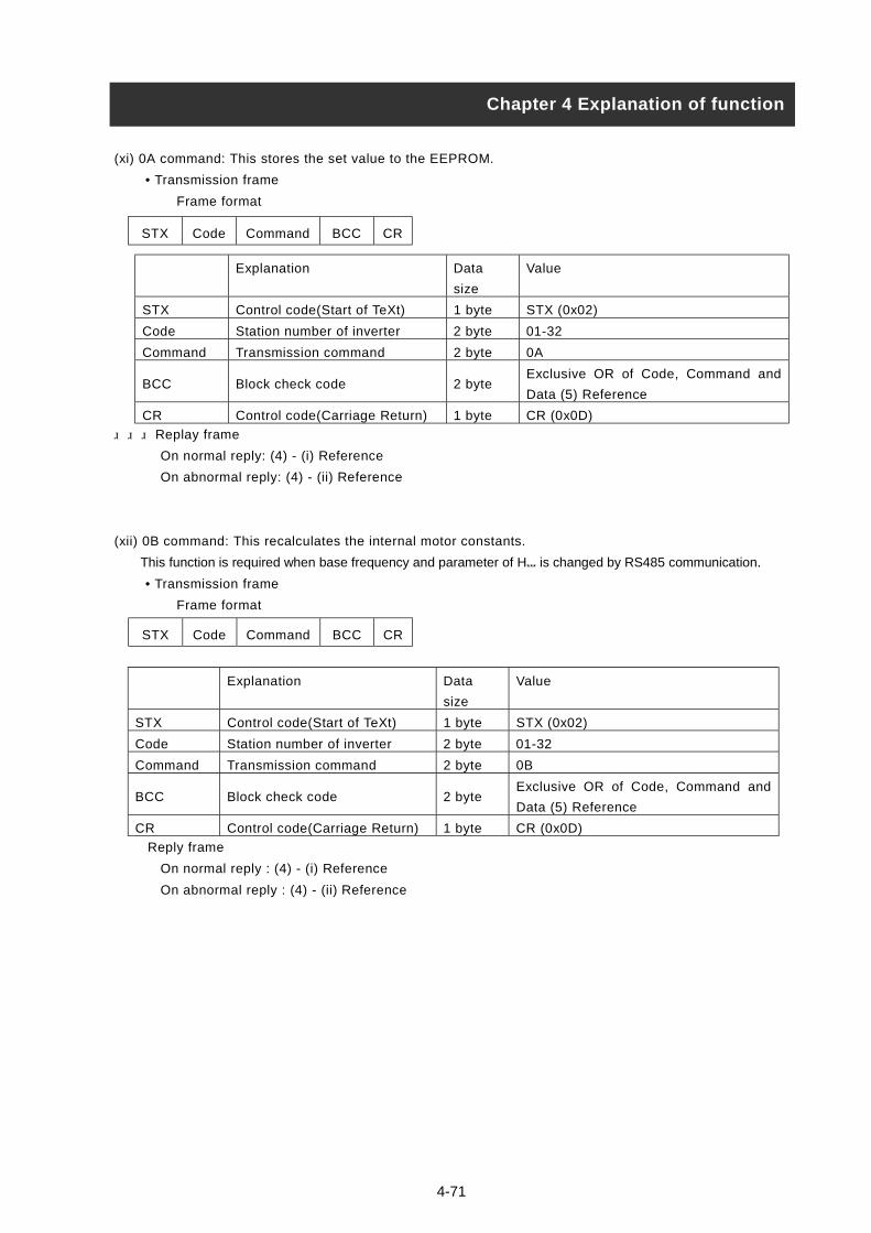
4-71
(xi) 0A command: This stores the set value to the EEPROM.
• Transmission frame
Frame format
Explanation Data
size
Value
STX Control code(Start of TeXt) 1 byte STX (0x02)
Code Station number of inverter 2 byte 01-32
Command Transmission command 2 byte 0A
BCC Block check code 2 byteExclusive OR of Code, Command and
Data (5) Reference
CR Control code(Carriage Return) 1 byte CR (0x0D)
Replay frame
On normal reply: (4) - (i) Reference
On abnormal reply: (4) - (ii) Reference
(xii) 0B command: This recalculates the internal motor constants.
This function is required when base frequency and parameter of H*** is changed by RS485 communication.
• Transmission frame
Frame format
Explanation Data
size
Value
STX Control code(Start of TeXt) 1 byte STX (0x02)
Code Station number of inverter 2 byte 01-32
Command Transmission command 2 byte 0B
BCC Block check code 2 byteExclusive OR of Code, Command and
Data (5) Reference
CR Control code(Carriage Return) 1 byte CR (0x0D)
Reply frame
On normal reply : (4) - (i) Reference
On abnormal reply : (4) - (ii) Reference
STX Code Command BCC CR
STX Code Command BCC CR
Chapter 4 Explanation of function
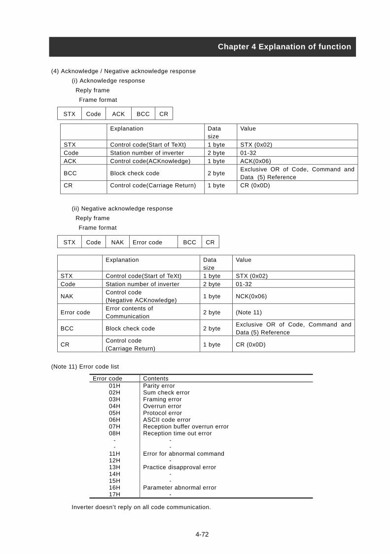
(4) Acknowledge / Negative acknowledge response
(i) Acknowledge response
Reply frame
Frame format
Explanation Datasize
Value
STX Control code(Start of TeXt) 1 byte STX (0x02)
Code Station number of inverter 2 byte 01-32
ACK Control code(ACKnowledge) 1 byte ACK(0x06)
BCC Block check code 2 byteExclusive OR of Code, Command andData (5) Reference
CR Control code(Carriage Return) 1 byte CR (0x0D)
(ii) Negative acknowledge response
Reply frame
Frame format
(Note 11) Error code list
Inverte
STX Code ACK BCC CR
STX Code NAK Error code BCC CR
Explanation Datasize
Value
STX Control code(Start of TeXt) 1 byte STX (0x02)
Code Station number of inverter 2 byte 01-32
NAKControl code(Negative ACKnowledge)
1 byte NCK(0x06)
Error codeError contents ofCommunication
2 byte (Note 11)
BCC Block check code 2 byteExclusive OR of Code, Command andData (5) Reference
CRControl code(Carriage Return)
1 byte CR (0x0D)
Chapter 4 Explanation of function
r doesn’t reply on all code communication.
Error code Contents01H Parity error02H Sum check error03H Framing error04H Overrun error05H Protocol error06H ASCII code error07H Reception buffer overrun error08H Reception time out error
- -- -
11H Error for abnormal command12H -13H Practice disapproval error14H -15H -16H Parameter abnormal error17H -
4-72

(5) About the calculation method of BCC (the Block Check Code)
(Example) 5Hz is set up by using 01 commands (the setting of the frequency command). (when the code
of the inverter of the object is “01” )
BCC is the result that transforms
every 1byte. In the case of the abo
3 0 3 1 3 0 3 1 3 0
(Appendix)ASCII code transfor
Code
1
Chapter 4 Explanation of function
Data
Command STXthe Code
ve transmi
3 0 3 0
mation tab
BCC
4-73
~Data int
ssion fram
3 5 3 0
le
Cha
CR
o ASCII Code and took an
e, BCC calculates it as follo
3 0
ASCII Code
racter data ASCII codA 4 1B 4 2C 4 3D 4 4E 4 5F 4 6
H 4 8
P 5 0
(0x 02)
(0x 30 30 30 35 30 30)
(0x 30 31)
(0x 30 31)
(0x 30 35)
(0x 0D)
0 1
0 1
0
EXCLUSIVE OR (Xor)
ws.
0 1Xo
3 X
0 0X
0 0X
3 0X
3 0X
0 5 ------ BCC numberXor
X 0 5
0 0 0 5 0 0
r
or
or
or
or
or
or
Xor
3 5Constitution of the transmission
e
Character data ASCII codeSTX 0 2ACK 06CR 0 DNCK 150 3 01 3 12 3 23 3 34 3 45 3 56 3 67 3 78 3 89 3 9

4-74
(6) Communication test mode
The communication test mode checks the communication line of RS485.
(The communication test mode procedure)
(i) Please remove the wiring of terminal unit TM2 of the control terminal unit foundation, to do the loop
back check.
(ii) Please set up the following with the operator of the inverter.
Please set up C071 (Communication transmission speed selection) to 02 (Loop Back Test).
(iii) Shut the power supply of the inverter at first and please turn on the power supply once again.
The check is started.
(iv) When the check ends the display is as follows.
Normal :
Abnormal :
(v) Please push the reset button of the digital operator or copy unit. And, the setting of C071 is returned
to the setting of an original request.
Chapter 4 Explanation of function
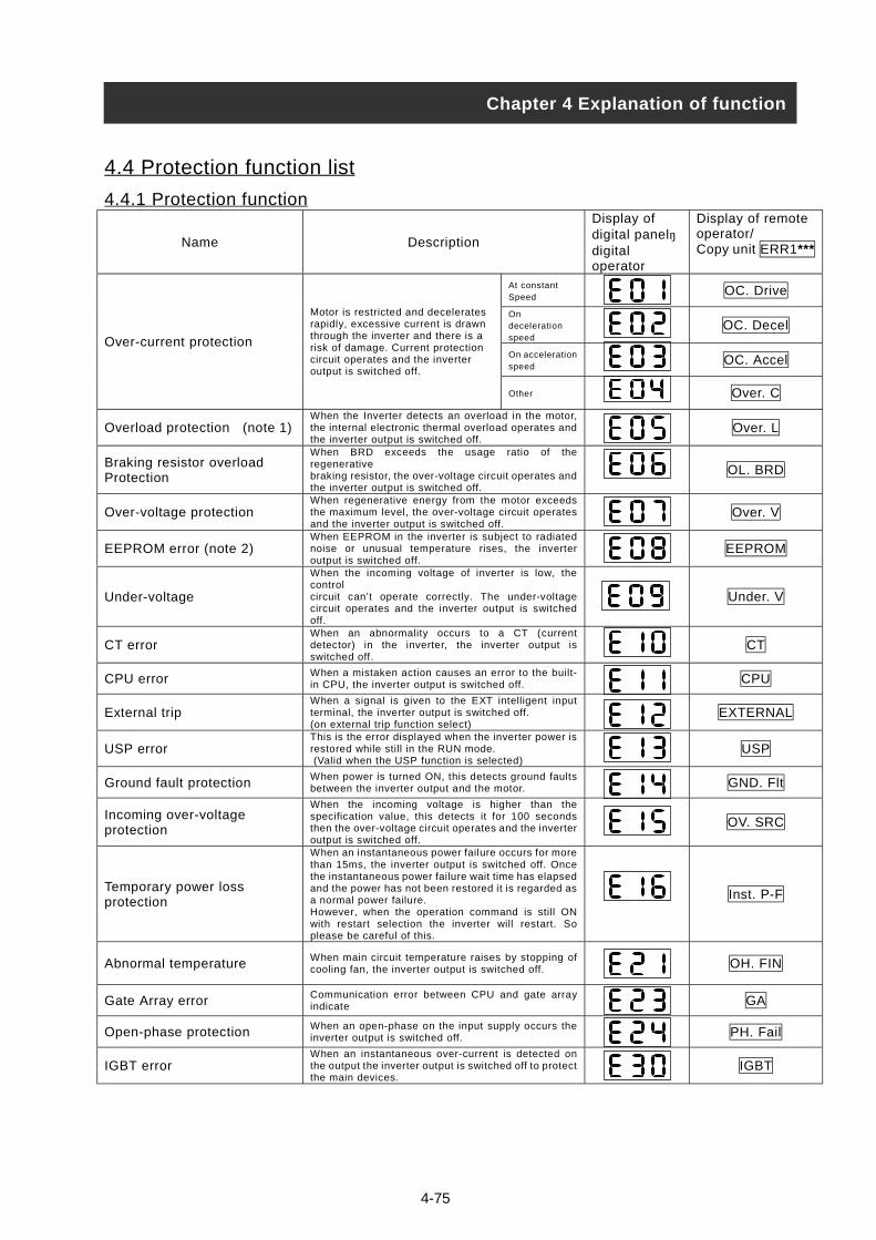
4-75
4.4 Protection function list
4.4.1 Protection function
Name Description
Display ofdigital panel・digitaloperator
Display of remoteoperator/Copy unit ERR1***
At constantSpeed
OC. Drive
Ondecelerationspeed
OC. Decel
On accelerationspeed
OC. AccelOver-current protection
Motor is restricted and deceleratesrapidly, excessive current is drawnthrough the inverter and there is arisk of damage. Current protectioncircuit operates and the inverteroutput is switched off.
Other Over. C
Overload protection (note 1)When the Inverter detects an overload in the motor,the internal electronic thermal overload operates andthe inverter output is switched off.
Over. L
Braking resistor overloadProtection
When BRD exceeds the usage ratio of theregenerativebraking resistor, the over-voltage circuit operates andthe inverter output is switched off.
OL. BRD
Over-voltage protectionWhen regenerative energy from the motor exceedsthe maximum level, the over-voltage circuit operatesand the inverter output is switched off.
Over. V
EEPROM error (note 2)When EEPROM in the inverter is subject to radiatednoise or unusual temperature rises, the inverteroutput is switched off.
EEPROM
Under-voltage
When the incoming voltage of inverter is low, thecontrolcircuit can’t operate correctly. The under-voltagecircuit operates and the inverter output is switchedoff.
Under. V
CT errorWhen an abnormality occurs to a CT (currentdetector) in the inverter, the inverter output isswitched off.
CT
CPU error When a mistaken action causes an error to the built-in CPU, the inverter output is switched off. CPU
External tripWhen a signal is given to the EXT intelligent inputterminal, the inverter output is switched off.(on external trip function select)
EXTERNAL
USP errorThis is the error displayed when the inverter power isrestored while still in the RUN mode. (Valid when the USP function is selected)
USP
Ground fault protection When power is turned ON, this detects ground faultsbetween the inverter output and the motor. GND. Flt
Incoming over-voltageprotection
When the incoming voltage is higher than thespecification value, this detects it for 100 secondsthen the over-voltage circuit operates and the inverteroutput is switched off.
OV. SRC
Temporary power lossprotection
When an instantaneous power failure occurs for morethan 15ms, the inverter output is switched off. Oncethe instantaneous power failure wait time has elapsedand the power has not been restored it is regarded asa normal power failure.However, when the operation command is still ONwith restart selection the inverter will restart. Soplease be careful of this.
Inst. P-F
Abnormal temperature When main circuit temperature raises by stopping ofcooling fan, the inverter output is switched off. OH. FIN
Gate Array error Communication error between CPU and gate arrayindicate GA
Open-phase protection When an open-phase on the input supply occurs theinverter output is switched off. PH. Fail
IGBT errorWhen an instantaneous over-current is detected onthe output the inverter output is switched off to protectthe main devices.
IGBT
Chapter 4 Explanation of function
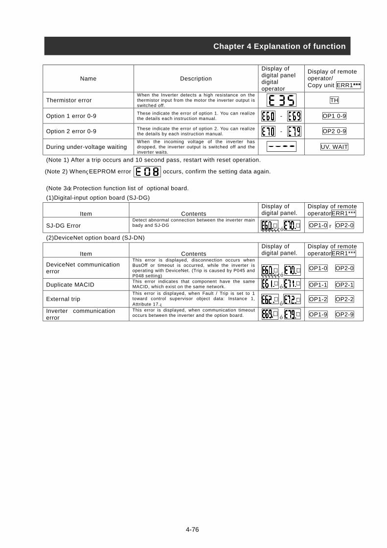
4-76
Name Description
Display ofdigital paneldigitaloperator
Display of remoteoperator/Copy unit ERR1***
Thermistor errorWhen the Inverter detects a high resistance on thethermistor input from the motor the inverter output isswitched off.
TH
Option 1 error 0-9 These indicate the error of option 1. You can realizethe details each instruction manual. - OP1 0-9
Option 2 error 0-9 These indicate the error of option 2. You can realizethe details by each instruction manual. - OP2 0-9
During under-voltage waitingWhen the incoming voltage of the inverter hasdropped, the inverter output is switched off and theinverter waits.
UV. WAIT
(Note 1) After a trip occurs and 10 second pass, restart with reset operation.
(Note 3)Protection function list of optional board.
(1)Digital-input option board (SJ-DG)
Item ContentsDisplay ofdigital panel.
Display of remoteoperatorERR1***
SJ-DG ErrorDetect abnormal connection between the inverter mainbady and SJ-DG
, OP1-0 OP2-0
(2)DeviceNet option board (SJ-DN)
Item ContentsDisplay ofdigital panel.
Displaoperat
DeviceNet communicationerror
This error is displayed, disconnection occurs whenBusOff or timeout is occurred, while the inverter isoperating with DeviceNet. (Trip is caused by P045 andP048 setting) ,
OP1-0
Duplicate MACIDThis error indicates that component have the sameMACID, which exist on the same network. , OP1-1
External tripThis error is displayed, when Fault / Trip is set to 1toward control supervisor object data: Instance 1,Attribute 17.。 ,
OP1-2
Inverter communicationerror
This error is displayed, when communication timeoutoccurs between the inverter and the option board. , OP1-9
(Note 2) When EEPROM error occurs, confirm the setting data again.
Chapter 4 Explanation of function
,
y of remoteorERR1***
OP2-0
OP2-1
OP2-2
OP2-9

(Note 4)If the inverter doesn't run normally or the inverter trips, check the dip switch and/or rotary switchsetting on optional board.
(1)Digital-input option board (SJ-DG)
(2
Th(
(No
Th
Chapter 4 Explanation of function
B(Biinp
O
B(B
inpO
Dip switchRotaryswitch
Setting frequencyAcceleration and
deceleration time setting
Torquelimit
setting
Positionsetting
TYPE CODE Setting resolution
Switch No.
1 2Settingcode
0.01Hz 0.1Hz 1Hz Rate 0.01sec 0.1sec 1sec 1% 1pulse
0
1
2
3
4
5
PAC(One time
inputmode at
OFF)
6
0
1
2
3
4
5
6
7
INnaryut atFF)/CDCDut atN)
DIV(Dividing
inputmode at
ON)
4-77
)DeviceNet option board (SJ-DN)e table below is the setting method of Baud rate (Front view of the option board.)., indicate direction for switch of Dip switch )
Baud rate 125kbps 250kbps 500kbps
Dip switchSetting
te) Do not switch on DR1 and DR0 at the same time.
e table below is the setting method of MAC ID (Front view of the option board)MAC ID Dip switch setting
Figure left describes the direction of Dip switches. See below. Bottom: 0 Upper: 1Bit increases from right to left switches.Therefore, figure left becomes formula below.1•2 +0•2 +1•2 +0•2 +0•2 +1•2 =29(Hex)=41(dec)
NA32 NA16 NA8 NA4 NA2 NA1
5 4 3 2 1 0
NA32 NA16 NA8 NA4 NA2 NA1
10
MAC ID
ON
OFFDR1 DR0
DRON
OFDR1 DR0
DRON
OFFDR1 DR0
DR
8
9
A
B

4-78
4.4.2 Trip monitor display
Chapter 4 Explanation of function
(1) Factor of trip, explanation of display
(2) Output frequency on trip. (Hz)
(3) Output current on trip (A)
(4) DC Link Voltage on trip. (V)
(5) Accumulated time that the inverter has been running. (h)
(6) Accumulated time that the inverter has been powered up. (h)
Display trip factor.
Please refer to 4. 4. 1.
Display the state of inverter on tripping.
: During reset.
: During stop.
: During deceleration.
: During constant speed.
: During acceleration.
: The state operation command is set with frequency command.
: During start.
: During DB.
: During overload restriction.
1 2
1 2
1 2
1 2
1 2
1 2

4-79
4.4.3 Warning Monitor displayWarning messages will appear when the data set is contradicting to others.
Program lamp (PRG) turns ON during the warning (until the data is changed).
Below is the description of the warnings.
Warning Codes <, > Basic code
001/ 201 frequency upper limiter A061/A261 >
002/ 202 frequency lower limiter A062/A262 >
004/ 204 Base frequency A003/A203 (Note 1) >
005/ 205 Output frequency F001, Multi stage speed 0 A020/A220 >
006/ 206 Multi stage speed 1~15 A021~A035 >
Maximum frequencyA004/A204
012/ 212 frequency upper limiter A062/A262 >
015/ 215 Output frequency F001, Multi stage speed 0 A020/A220 >
016/ 216 Multi stage speed 1~15 A021~A035 >
frequency upper limiterA061/A261
021/ 221 frequency upper limiter A061/A261 <
025/ 225 Output frequency F001, Multi stage speed 0 A020/A220 <
frequency lower limiterA062/A262
031/ 231 frequency upper limiter A061/A261 <
032/ 232 frequency lower limiter A062/A262 <
035/ 235 Output frequency F001, Multi stage speed 0 A020/A220 <
036 Multi stage speed 1~15 A021~A035 <
037 Jogging frequency A038 <
Starting frequency b082
085/ 285 Output frequency F001, Multi stage speed 0 A020/A220 <>
086 Multi stage speed 1~15 A021~A035 <>
Jump frequency 1/2/3+- Jump widthA063+-A064A065+-A066A067+-A068 (Note 2)
091/ 291 frequency upper limiter A061/A261 >
092/ 292 frequency lower limiter A062/A262 >
095/ 295 Output frequency F001, Multi stage speed 0 A020/A220 >
096 Multi stage speed 1~15 A021~A035 >
Free v/f frequency 1~6 b100, b102, b104, b106, b108, b110 >
Free v/f frequency 7 b112
Free v/f frequency 2~6 b102, b104, b106, b108, b110 < Free v/f frequency 1 b100
Free v/f frequency 1 b100 >
Free v/f frequency 3~6 b104, b106, b108, b110 <Free v/f frequency 2 b102
Free v/f frequency 1, 2 b100, b102 >
Free v/f frequency 4~6 b106, b108, b110 <Free v/f frequency 3 b104
Free v/f frequency 1~3 b100, b102, b104 >
Free v/f frequency 5, 6 b108~b110 <Free v/f frequency 4 b106
Free v/f frequency 1~4 b100, b102, b104, b106 >
Free v/f frequency 6 b110 <Free v/f frequency 5 b108
110
Free v/f frequency 1~5 b100, b102, b104, b106, b108 > Free v/f frequency 6 b110
Free electronic thermal frequency 2, 3 b017, b019 <Free electronic thermalfrequency 1 b015
Free electronic thermal frequency 1 b015 >
Free electronic thermal frequency 3 b019 <Free electronic thermalfrequency 2 b017
120
Free electronic thermal frequency 1, 2 b015, b017 >Free electronic thermalfrequency 3 b019
Warning is cleared when the setting fulfils the above condition.
Data will be changed automatically to the basic code.
(Note 1) In case of this, the Base frequency will be changed to Maximum frequency. Because it has the
possibility that the motor is damaged according to the value, please set the correct data when the
004/ 204 will appear.
(Note 2) The jump frequency will be automatically re-written to the lowest jump frequency (= Jump frequency
– jump width)
Chapter 4 Explanation of function
d090 : Warning Monitor
Relation code

5-1
• After a lapse of more than 10 minutes after turning off the input power supply, performthe maintenance and inspection.
Otherwise, there is a danger of electric shock.
• Make sure that only qualified persons will perform maintenance, inspection and partreplacement. (Before starting the work, remove metallic objects from your person(wristwatch, bracelet, etc.)(Be sure to use tools protected with insulation.)
Otherwise, there is a danger of electric shock and/or injury.
5.1 Precautions for Maintenance/Inspection
5.1.1 Daily inspectionEvery day before operation check the following;
[1] Does the motor operate according to the settings?[2] Is there any trouble with the surroundings of the installation?[3] Is there any trouble with the cooling or ventilation system?[4] Is there any abnormal vibration or sound?[5] Are their any signs of over-current or discoloration?[6] Is their any unusual odour present?
Check the input voltage to the inverter by using a meter during running[1] Is the supply voltage constant?[2] Are all the phases of the supply balanced?
5.1.2 CleaningMake sure that the inverter is not dirty when operating.Wipe clean with a soft cloth and synthetic detergent or ethanol.
(Note) Don’t use solvents containing any of the following, acetone, benzene, toluene,alcohol etc. as they can cause melting of the inverter surface, peeling of paint.Never clean the display part of the digital operator with detergent or alcohol.
5.1.3 Regular inspectionInspections should be regularly carried out on the parts that can’t be inspected while theinverter is running.
[1] Is there any trouble with the cooling system? - - - Cleaning of air filter etc.[2] Check that all screw terminals and fixings are tight as they may loosen due to
vibration or temperature change etc.[3] Is there any corrosion, damage to insulators?[4] Measurement of insulation resistance.[5] Check of cooling fan, smoothing capacitor, relay and exchange if necessary.
Chapter 5 Maintenance, Inspection
WARNING
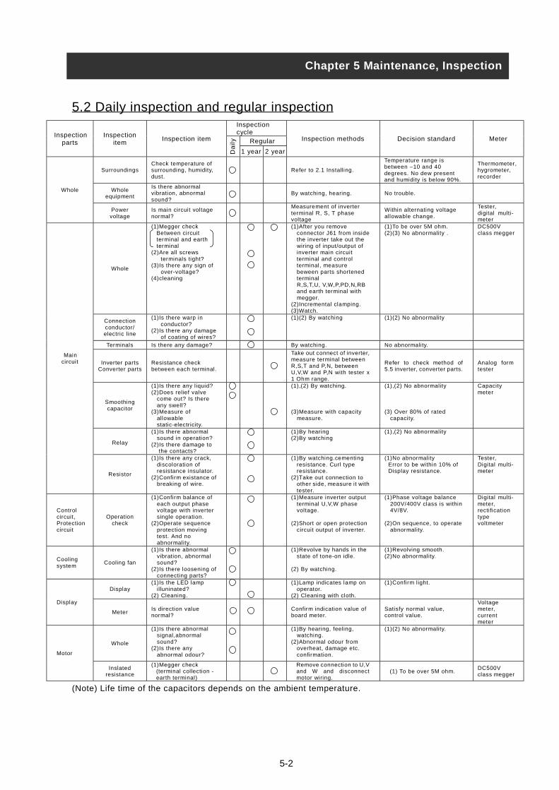
5.2 Daily inspection and regular inspectionInspectioncycleInspection
partsInspection
itemInspection item Inspection methods Decision standard Meter
SurroundingsCheck temperature ofsurrounding, humidity,dust.
Wholeequipment
Is there abnormalvibration, abnormalsound?
Whole
Powervoltage
Is main circuit voltagenormal?
Whole
(1)Megger checkBetween circuitterminal and earthterminal
(2)Are all screws terminals tight?(3)Is there any sign of over-voltage?(4)cleaning
Connectionconductor/electric line
(1)Is there warp in conductor?(2)Is there any damage of coating of wires?
Terminals Is there any damage?
Inverter partsConverter parts
Resistance checkbetween each terminal.
Smoothingcapacitor
(1)Is there any liquid?(2)Does relief valve
come out? Is thereany swell?
(3)Measure of allowable static-electricity.
Relay
(1)Is there abnormal sound in operation?(2)Is there damage to the contacts?
Maincircuit
Resistor
(1)Is there any crack, discoloration of resistance insulator.(2)Confirm existance of breaking of wire.
Controlcircuit,Protectioncircuit
Operationcheck
(1)Confirm balance of each output phase voltage with inverter single operation.(2)Operate sequence protection moving test. And no abnormality.
Coolingsystem
Cooling fan
(1)Is there abnormal vibration, abnormal sound?(2)Is there loosening of connecting parts?
Display(1)Is the LED lamp illuninated?(2) Cleaning.
Display
MeterIs direction valuenormal?
Whole
(1)Is there abnormalsignal,abnormalsound?
(2)Is there any abnormal odour?Motor
Inslatedresistance
(1)Megger check(terminal collection -earth terminal)
(Note) Life time of the capacitors depend
Chapter 5 Maintenance, Inspection
Da
ily
Reg1 year
s on t
ular
2 year
5-2
Refer to 2.1 Installing.
Temperature range isbetween –10 and 40degrees. No dew presentand humidity is below 90%.
Thermometer,hygrometer,recorder
By watching, hearing. No trouble.
Measurement of inverterterminal R, S, T phasevoltage
Within alternating voltageallowable change.
Tester,digital multi-meter
(1)After you remove connector J61 from inside the inverter take out the wiring of input/output of inverter main circuit terminal and control terminal, measure beween parts shortened terminal R,S,T,U, V,W,P,PD,N,RB and earth terminal with megger.(2)Incremental clamping.(3)Watch.
(1)To be over 5M ohm.(2)(3) No abnormality .
DC500Vclass megger
(1)(2) By watching (1)(2) No abnormality
By watching. No abnormality.
Take out connect of inverter,measure terminal betweenR,S,T and P,N, betweenU,V,W and P,N with tester x1 Ohm range.
Refer to check method of5.5 inverter, converter parts.
Analog formtester
(1),(2) By watching.
(3)Measure with capacity measure.
(1),(2) No abnormality
(3) Over 80% of rated capacity.
Capacitymeter
(1)By hearing(2)By watching
(1),(2) No abnormality
(1)By watching.cementing resistance. Curl type resistance.(2)Take out connection to
other side, measure it withtester.
(1)No abnormality Error to be within 10% of Display resistance.
Tester,Digital multi-meter
(1)Measure inverter output terminal U,V,W phase voltage.
(2)Short or open protection circuit output of inverter.
(1)Phase voltage balance 200V/400V class is within 4V/8V.
(2)On sequence, to operate abnormality.
Digital multi-meter,rectificationtypevoltmeter
(1)Revolve by hands in the state of tone-on idle.
(2) By watching.
(1)Revolving smooth.(2)No abnormality.
(1)Lamp indicates lamp on operator.(2) Cleaning with cloth.
(1)Confirm light.
Confirm indication value ofboard meter.
Satisfy normal value,control value.
Voltagemeter,currentmeter
(1)By hearing, feeling, watching.(2)Abnormal odour from overheat, damage etc. confirmation.
(1)(2) No abnormality.
Remove connection to U,Vand W and disconnectmotor wiring.
(1) To be over 5M ohm.DC500Vclass megger
he ambient temperature.
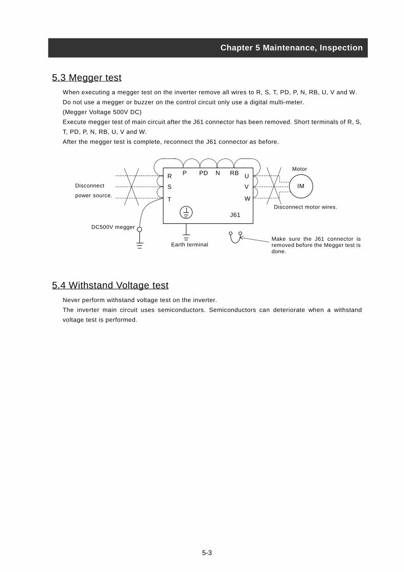
5-3
5.3 Megger test
When executing a megger test on the inverter remove all wires to R, S, T, PD, P, N, RB, U, V and W.
Do not use a megger or buzzer on the control circuit only use a digital multi-meter.
(Megger Voltage 500V DC)
Execute megger test of main circuit after the J61 connector has been removed. Short terminals of R, S,
T, PD, P, N, RB, U, V and W.
After the megger test is complete, reconnect the J61 connector as before.
5.4 Withstand Voltage test
Never perform withstand voltage test on the inverter.
The inverter main circuit uses semiconductors. Semiconductors can deteriorate when a withstand
voltage test is performed.
Chapter 5 Maintenance, Inspection
IM
R
S
T
U
V
P PD N RB
J61
Earth terminal
Disconnect
power source.
Motor
Make sure the J61 connector isremoved before the Megger test isdone.
DC500V megger
Disconnect motor wires.
W

5-4
5.5 The method to check Inverter, converter part
A test is possible to check quality.
(Preparation)
[1] Take out the power lines (R, S and T) connected to the inverter, the motor connection lines (U, V and
W) and the regenerative control resistance (P and RB).
[2] Prepare tester. (Using range of 1 ohm resistance measure range.)
(How to check)
It is possible to check the quality of the charging state of the terminals R, S, T, U, V, W, RB, P and N of
the inverter and the pole of the tester by measuring the charging state.
(Note 1) Before you measure the voltage between P and N with DC current range, confirm that the
smoothing capacitor is discharged fully, execute checks.
(Note 2) Almost infinite value is indicated on no conducting.
With the effect of the smoothing capacitor, the inverter conducts instantly and an infinite value isn’t
indicated. Ohm-number 10 ohms is indicated on conducting.
The values indicated will not be exactly the same for each terminal, however they will be very close
together. If there is a significant difference a problem may exist.
Pole of tester
(Red) (Black)
Measure
value
R PD No-conductD1
PD R Conduct
S PD No-conductD2
PD S Conduct
T PD No-conductD3
PD T Conduct
R N ConductD4
N R No-conduct
S N ConductD5
N S No-conduct
T N Conduct
Co
nve
rte
r
D6
N T No-conduct
U P No-conductTR1
P U Conduct
V P No-conductTR2
P V Conduct
W P No-conductTR3
P W Conduct
U N ConductTR4
N U No-conduct
V N ConductTR5
N V No-conduct
W N Conduct
Inve
rte
r
TR6
N W No-conduct
RB P No-conduct
P RB Conduct
RB N No-conductBR
pa
rt
TR7
N RB No-conduct
Chapter 5 Maintenance, Inspection
Converter InverterPD P
D1 D2 D3
C +
RB
TR4 TR5 TR6
TR1 TR2 TR3
N
D4 D5 D6
U
V
W
R
S
T
TR7

5-5
5.6 Capacitor Life Curve
(Note 1)
Ambient air temperature means the surrounding temperature of the inverter. In case the inverter is
installed in a cabinet, ambient air temperature is the temperature of the internal air of the cabinet.
(Note 2)
DC bus capacitors are recommended to be replacing every 5 years. And if the inverter is used in a worse
condition, this recommended replacing period is reduced.
Chapter 5 Maintenance, Inspection
10
20
30
40
1
Ambient temperature (ºC)
50
0
-102 3 4 5 6 7 8 9 10 Life time (year)
12h/day operation
24h/day operation

6-1
6.1Standard specification list200V class
Inverter ModelL300P110LF
L300P150LF
L300P185LF
L300P220LF
L300P300LF
L300P370LF
L300P450LF
L300P550LF
L300P750LF
Enclosure(Note 1)
IP20(NEMA1)
Max. Applicadie Motor 4P(kW) (Note 2)
11 15 18.5 22 30 37 45 55 75
200V 15.2 20.0 25.2 29.4 39.1 48.4 58.5 72.7 93.5Rated inputAlternatingvoltage(kVA) 240V 18.2 24.1 30.3 35.3 46.9 58.1 70.2 87.2 112.2
Rated input alternatingvoltage
Three-phase 200-240V (±10%) 50Hz/60Hz
Rated output voltage(Note 3)
Three-phase 200-240V (This corresponds to receiving voltage.)
Rated output current (A) 44 58 73 85 113 140 169 210 270Control system Sine-wave modulation PWM system.Output frequency range(Note 4)
0.1-400Hz
Frequency accuracy Digital command ±0.01% for Max. frequency, analog frequency ±0.2%(25±10ºC)Frequency resolvingpower
Digital setting: 0.01Hz, analog setting:Max. frequency /4000
Voltage/frequencycharacteristic
V/f option variable, V/f control, (constant torque, reduced torque)
Overload current rate 120% for 60 seconds, 150% for 0.5secondAcceleration/deceleration time
0.01-3,600seconds (straight or S-Curve on acceleration, deceleration is optional setting individually), 2nd adjustable setting is possible.
RegenerativeControl(short duration)(Note 5)
BRD circuit built-in(Discharge resis-tance is required.)
Regenerative unit is required.
Con
trol
DC BrakingOn starting and decelerating by stop command, inverter operates under operation setting frequency. Or inverter operates with external input(Breaking power, time, frequency can be set.)
Operator Setting by keys
Volume Setting with potentiometer on the digital operator (Built-in as standard) (Analog setting)ExternalSignal
DC 0 to 10V, -10 to +10V (input impedance 10k ohm), 4 to 20mA (input impedance 100 ohm)Freq-uency
Externalport
Setting with RS485 communication
Operator Run/Stop (forward changes with code)External
signalForward Run/Stop (1a connect), reverse command is impossible on assigning of terminal (selection of 1a, 1b is possible), input of 3 wires is possible.Run/
StopExternalport
Setting with RS485.
Intelligent inputterminal
Use by selecting terminals from;Reverse command (RV), multi-speed1-4 (CF1-CF4), jogging (JG), external dc braking (DB), 2nd control (SET),2nd acceleration (2CH), free-run stop (FRS), external trip (EXT),USP function (USP), commercial change (CS),software lock (SFT), analog input voltage / current / select (AT), reset inverter (RS), 3 wire run (STA),3 wire keep (STP), 3 wire direction selection (F/R), PID selection valid/invalid (PID), PID integrating reset (PIDC), remote control,up function (UP), remote control down function (DWN),remote control data clear (UDC), multi-speed bit 1-7(SF1-SF7),overload ristriction change (OLR), no assign (NO)
Inpu
t sig
nal
Thermistor inputterminal
1 terminal
Intelligent outputterminal
2 relay outputs (1a contact), relay(1c contact), output relay selection as follows;(selection from during running, on arrival with constant speed, over setting frequency, PID over-deviation)
Out
put
il
Intelligent monitoroutput terminal
Analog voltage output, analog current output, pulse line output
Display monitor Output frequency, output current, frequency conversion value, trip history, input output terminal state, input electric power, output voltage.
Other functionV/f free setting (5 points), Upper / lower frequency limitter, Frequency jump, Curve adjustable speed, Manual torque boost level / Braking point,Analog meter adjustment,Starting frequency, Carrier frequency adjustment, Electronic thermal free setting, External start/end (frequency/rate),Analog input selection, Trip retry, Reduced voltage start,Overload restriction
Carrier frequencyrange
0.5-12 kHz
Protection functionOver-current, over-voltage, under-voltage, electronic thermal level, abnormal trouble, ground fault current on starting, instantaneous stop, USP error, open-phase error, control resistoroverload, CT error, external trip, communication error
Frequencytemperature/Preservationtemperature(Note 6) /humidty
-10 to 40ºC (Note 10) / -20 to 65ºC / 20 to 90% RH (installed with no dew condensation)
Vibration (Note 7) 5.9m2 / S (0.6G), 10-55Hz 2.94m2 / S (0.3G), 10-55Hz
Usa
gesu
rrou
ndin
gs
Using place Under 1,000m above sea level, indoors (installed away from corrosive gasses, dust)(Note 8) Paint color Blue (D.I.C14 version No.436) Gray(MUNSELL 8.5YR6.2/0.2)
OptionsOperator with copy function, cable for operator, braking resistor, regenerative control unit, alternating reactor, D.C. reactor, EMC Mains filter, higher harmoniccontrol unit, LCR filter, applied control installation
Remote operator OPE-SR, cable for remote operation ICS-1(1m), ICS3(3m) (Note 9)Schematic mass (kg) 5 5 12 12 12 20 30 30 50
(Note 1) Protective system bases on JME1030.
(Note 2) Applicable motor indicates HITACHI three-phase motor. When you use other motor, set so that the motor current doesn’t exceed the rated current of the inverter.
(Note 3) Output voltage will reduce when the power voltage is reduced. (Except when AVR function is selected.)
(Note 4) When you operate motor over 50/60Hz, inquire about the allowable max.revolution time of motor etc. from motor manufacturer.
(Note 5) Braking resistance isn’t installed in the inverter. When the inverter requires a high regenerative torque, use optional braking resistance and regenerative braking unit.
(Note 6) Protective temperature is temperature during transportation.
(Note 7) This bases on the test methods of JIS C0911(1984).
(Note 8) When the inverter is used in a place with dust, we recommend the optional varnish coating specification. Before it is required.
(Note 9) When you use cable for remote operation, please remove connector. Please refer to 1.3 Appearance.
(Note 10) When using at 50ºC of ambient air temperature, the rated output current will be reduced. (P.4-18)
(Note) Insulation distance is based on UL, CE standard.
Chapter 6 Specification
1 2

6-2
400V class
Inverter ModelL300P110HF
L300P150HF
L300P185HF
L300P220HF
L300P300HF
L300P370HF
L300P450HF
L300P 550HF
L300P750HF
L300P900HF
L300P1100HF
L300P1320HF
Enclosure(Note 1)
IP20(NEMA1) IP00
Max. Applicadie Motor 4P(kW) (Note 2) 11 15 18.5 22 30 37 45 55 75 90 110 132
400V 15.2 20.0 25.6 29.7 39.4 48.4 58.8 72.7 93.5 110.8 135.0 159.3Rated inputAlternatingvoltage(kVA) 480V 18.2 24.1 30.7 35.7 47.3 58.1 70.1 87.2 112.2 133.0 162.1 191.2
Rated input alternatingVoltage
Three-phase 380-480V (±10%) 50Hz/60Hz
Rated output voltage(Note 3)
Three-phase 380-480V (This corresponds to receiving voltage.)
Rated output current (A) 22 29 37 43 57 70 85 105 135 160 195 230Control system Sine-wave modulation PWM system.Output frequency range(Note 4)
0.1-400Hz
Frequency accuracy Digital command ±0.01% for Max. frequency, analog frequency ±0.2%(25±10ºC)Frequency resolvingPower
Digital setting: 0.01Hz, analog setting: Max. frequency /4000
Voltage/frequencycharacteristic
V/f option variable, V/f control, (constant torque, reduced torque)
Overload current rate 120% for 60 seconds, 150% for 0.5secondAcceleration/Deceleration time
0.01-3,600seconds (straight or S-Curve on acceleration, deceleration is optional setting individually), 2nd adjustable setting is possible.
RegenerativeControl(short duration)(Note 5)
BRD circuit built-in(Discharge resis-tance isrequired.)
Regenerative unit is required.
Con
trol
DC BrakingOn starting and decelerating by stop command, inverter operates under operation setting frequency. Or inverter operates with external input(Breaking power, time, frequency can be set.)
Operator Setting by keys
Volume Setting with potentiometer on the digital operator (Built-in as standard) (Analog setting)ExternalSignal
DC 0 to 10V, -10 to +10V (input impedance 10k ohm), 4 to 20mA (input impedance 100 ohm)Freq-uency
Externalport
Setting with RS485 communication
Operator Run/Stop (forward changes with code)Externalsignal
Forward Run/Stop (1a connect), reverse command is impossible on assigning of terminal (selection of 1a, 1b is possible), input of 3 wires is possible.Run/Stop
Externalport
Setting with RS485.
Intelligent inputTerminal
Use by selecting terminals from;Reverse command (RV), multi-speed1-4 (CF1-CF4), jogging (JG), external dc braking (DB), 2nd control (SET),2nd acceleration (2CH), free-run stop (FRS), external trip (EXT),USP function (USP), commercial change (CS),software lock (SFT), analog input voltage / current / select (AT), reset inverter (RS), 3 wire run (STA),3 wire keep (STP), 3 wire direction selection (F/R), PID selection valid/invalid (PID), PID integrating reset (PIDC), remote control,up function (UP), remote control down function (DWN),remote control data clear (UDC), multi-speed bit 1-7(SF1-SF7),overload ristriction change (OLR), no assign (NO)
Inpu
t sig
nal
Thermistor inputTerminal
1 terminal
Intelligent outputTerminal
2 relay outputs (1a contact), relay(1c contact), output relay selection as follows;(selection from during running, on arrival with constant speed, over setting frequency, PID over-deviation)
Out
put
il
Intelligent monitorOutput terminal
Analog voltage output, analog current output, pulse line output
Display monitor Output frequency, output current, frequency conversion value, trip history, input output terminal state, input electric power, output voltage.
Other functionV/f free setting (5 points), Upper / lower frequency limitter, Frequency jump, Curve adjustable speed, Manual torque boost level / Braking point,Analog meter adjustment,Starting frequency, Carrier frequency adjustment, Electronic thermal free setting, External start/end (frequency/rate),Analog input selection, Trip retry, Reduced voltage start,Overload restriction
Carrier frequencyRange
0.5-12 kHz 0.5-8 kHz
Protection functionOver-current, over-voltage, under-voltage, electronic thermal level, abnormal trouble, ground fault current on starting, instantaneous stop, USP error, open-phase error, control resistoroverload, CT error, external trip, communication error
Frequencytemperature/Preservationtemperature(Note 6) /humidty
-10 to 40ºC (Note 10) / -20 to 65ºC / 20 to 90% RH (installed with no dew condensation)
Vibration (Note 7) 5.9m2 / S (0.6G), 10-55Hz 2.94m2 / S (0.3G), 10-55Hz
Usa
gesu
rrou
ndin
gs
Using place Under 1,000m above sea level, indoors (installed away from corrosive gasses, dust)(Note 8) Paint color Blue (D.I.C14 version No.436) Gray (MUNSELL 8.5YR6.2/0.2)
OptionsOperator with copy function, cable for operator, braking resistor, regenerative control unit, alternating reactor, D.C. reactor, EMC Mains filter, higher harmoniccontrol unit, LCR filter, applied control installation
Remote operator OPE-SR, cable for remote operation ICS-1(1m), ICS-3(3m) (Note 9)Schematic mass (kg) 5 5 12 12 12 20 30 30 30 60 60 80
(Note 1) Protective system bases on JME1030.
(Note 2) Applicable motor indicates HITACHI three-phase motor. When you use other motor, set so that the motor current doesn’t exceed the rated current of the inverter.
(Note 3) Output voltage will reduce when the power voltage is reduced. (Except when AVR function is selected.)
(Note 4) When you operate motor over 50/60Hz, inquire about the allowable max.revolution time of motor etc. from motor manufacturer.
(Note 5) Braking resistance isn’t installed in the inverter. When the inverter requires a high regenerative torque, use optional braking resistance and regenerative braking unit.
(Note 6) Protective temperature is temperature during transportation.
(Note 7) This bases on the test methods of JIS C0911(1984).
(Note 8) When the inverter is used in a place with dust, we recommend the optional varnish coating specification. Before it is required.
(Note 9) When you use cable for remote operation, please remove connector. Please refer to 1.3 Appearance.
(Note 10) When using at 50ºC of ambient air temperature, the rated output current will be reduced. (P.4-18)
(Note ) Insulation distance is based on UL, CE standard.
Chapter 6 Specification
1 2
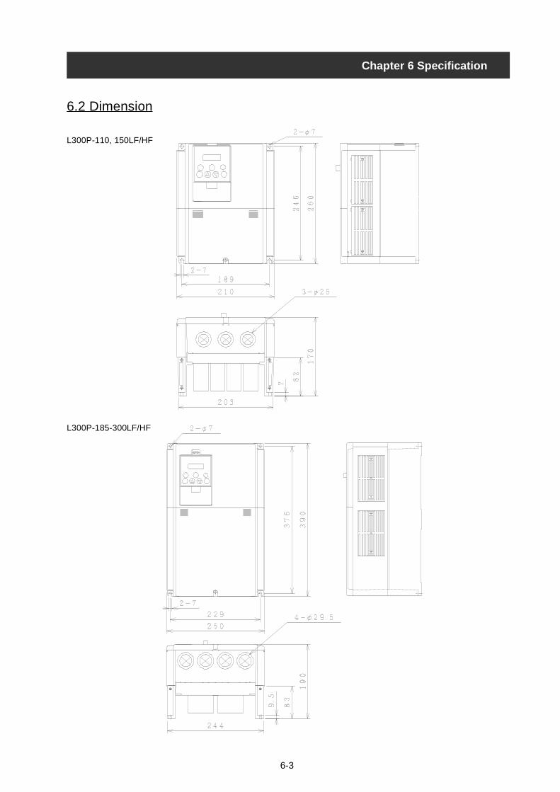
6-3
Chapter 6 Specification
6.2 Dimension
L300P-110, 150LF/HF
L300P-185-300LF/HF
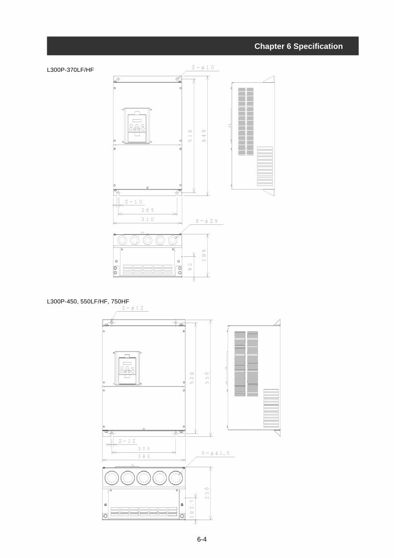
6-4
Chapter 6 Specification
L300P-370LF/HF
L300P-450, 550LF/HF, 750HF
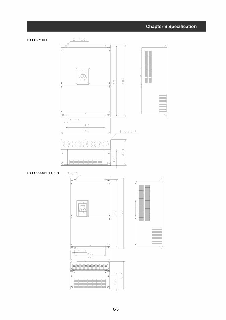
6-5
Chapter 6 Specification
L300P-750LF
L300P-900H, 1100H
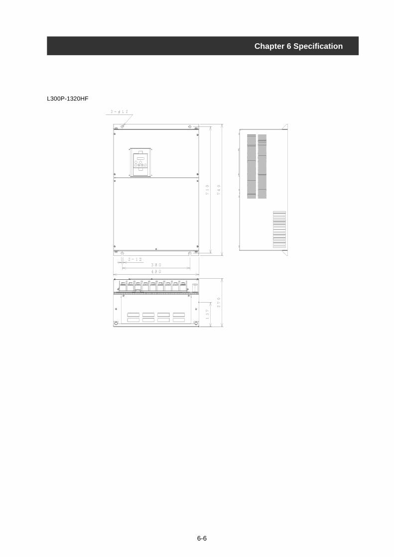
6-6
Chapter 6 Specification
L300P-1320HF