instruction manual - hobbicomanuals.hobbico.com/gpm/gpma0177-manual.pdf · instruction manual...
TRANSCRIPT

Instruction Manual
WARRANTY
Great Planes Model Manufacturing Co. guarantees this kit to be free from defects in both material and workmanshipat the date of purchase. This warranty does not cover any component parts damaged by use or modification. In no caseshall Great Planes' liability exceed the original cost of the purchased kit. Further, Great Planes reserves the rightto change or modify this warranty without notice.
In that Great Planes has no control over the final assembly or material used for final assembly, no liability shall beassumed nor accepted for any damage resulting from the use by the user of the final user-assembled product. By theact of using the user-assembled product, the user accepts all resulting liability.
If the buyers are not prepared to accept the liability associated with the use of this product, they areadvised to return this kit immediately in new and unused condition to the place of purchase.
R E A D T H R O U G H T H I S I N S T R U C T I O NMANUAL FIRST. IT CONTAINS IMPORTANTINSTRUCTIONS AND WARNINGS CONCERNINGTHE ASSEMBLY AND USE OF THIS MODEL.
CRS4P03 11/95 V.1 3005058
PO Box 788 Urbana, Illinois 61801 (217)398-8970
Entire Contents © Copyright 1995

Precautions ....................................................3Introduction....................................................3
Decisions you must make.............................3Engine selection.........................................3Other items required...................................3Suggested supplies and tools ....................4Common abbreviations...............................4Metric conversions .....................................5Types of wood ............................................5Get ready to build.......................................5
Die-cut patterns..............................................6
Build the tail surfaces....................................7Build the stabilizer and fin ..........................7Build the elevators and rudder....................7Join the elevators .......................................7Finishing the tail surfaces...........................8
Build the wing ................................................8Build the wing center section......................8Sheet the top of the center section...........10Sheet the bottom of the center section..... 12Trailing edge installation...........................13Build the outer wing panels ......................14Sheet the bottom LE and TE ....................15Sheet the top LE and TE ..........................16Join the wing panels.................................17Install the aileron linkage..........................17
Build The Fuselage ......................................20Assemble the fuse sides ..........................20Install pushrod tubes ................................21Build the tail gear......................................21Install the firewall......................................22Install the engine and tank .......................23Complete the fuse top ..............................25Mount the wing to the fuselage ................27Attach the stabilizer blocks.......................27Install the stab and fin ..............................29Build the wing belly fairing........................30Install the cowl..........................................31
Finishing.......................................................32Final sanding............................................32Fuelproofing .............................................32Balance the airplane laterally ...................32Cover the structure with MonoKote film....33Recommended covering sequence..........33Painting the cowling..................................33
Final Hookups And Checks.........................34Install the control surfaces........................34Install the landing gear and canopy..........35Radio installation ......................................35
Balance your model..................................37Preflight....................................................38AMA safety code ......................................38
Flying your model ........................................39
Two-view drawing ..........................Back Cover
Your F4U Corsair is not a toy, but rather a sophisticated,working model that funct ions very much like anactual airplane.
Because of its realistic performance, the Corsair, if notassembled and operated correctly, could possibly causeinjury to yourself or spectators and damage property.
To make your R/C modeling experience totallyenjoyable, we recommend that you get experienced,knowledgeable help with assembly and during yourfirst flights. You'll learn faster and avoid risking your modelbefore you're truly ready to solo. Your local hobby shop hasinformation about f ly ing clubs in your area whosemembership includes qualified instructors.
You can also contact the national Academy of ModelAeronautics (AMA), which has more than 2,300 charteredclubs across the country. Through any one of them,instructor training programs and insured newcomer trainingare available.
Contact AMA at the address or toll-free phone number below:
Academy of Model Aeronautics5151 East Memorial DriveMuncie, IN 47302-9252(800) 435-9262
1 You must assemble the plane according to theinstructions Do not alter or modify the model, as doing somay result in an unsafe or unflyable model In a few casesthe instructions may differ slightly from the photos In thoseinstances you should assume the written instructionsare correct.
2 You must take time to build straight, true and strong.
3 You must properly install all R/C and other componentsso that the model operates properly on the ground and inthe air
4. You must test the operation of the model before the firstand each successive flight to insure that all equipment isoperating, and you must make certain that the model hasremained structurally sound
Remember: Take your time and follow directions toend up with a well-built model that is straight and true.
The Great Planes F4U Corsair .40 has been designedto be built flat on the board. It is a super-flying model withno bad traits Anyone who has had a little taildragger timewill not experience any difficulty with ground handling orflying With a hot 40 or .46, the Great Planes Corsair willdo all the tricks in the book, and at a very exciting paceInstall a non-Schnuerled engine and enjoy a more relaxedflying experience - but one that still allows most commonflight maneuvers
The Corsair .40 is equally at home on a paved runwayor operating from a grass strip The construction is toughand there are no retracts to worry about, so rough fieldscan be handled with confidence The thick, high-lift airfoilwith built-in washout allows the model to slow down forsmooth landings without the need for flaps
To fully enclose the engine within the Corsair's cowl, wesuggest using a 2-stroke engine with a Pitts-style mufflerThere is plenty of room to install up to a 70 4-stroke if youchoose However, the top of the cylinder head and exhaustpipe/muffler will protrude through the cowling
We hope you enjoy your Great Planes F4U Corsair .40as much as we do It's a blast to fly!
Please inspect all parts carefully before starting tobuild. If any parts are missing, broken or defective, or ifyou have any questions about building or flying thismodel, please give us a call at (217) 398-8970 and we'll beglad to help.
Thank you for purchasing the Great Planes F4UCorsair 40 to build as your next project' This kit has beenengineered using state-of-the-art Computer Aided Designtechnology to provide the best parts fit and interlockingconstruction available The result is a kit that builds easilyand flies great.
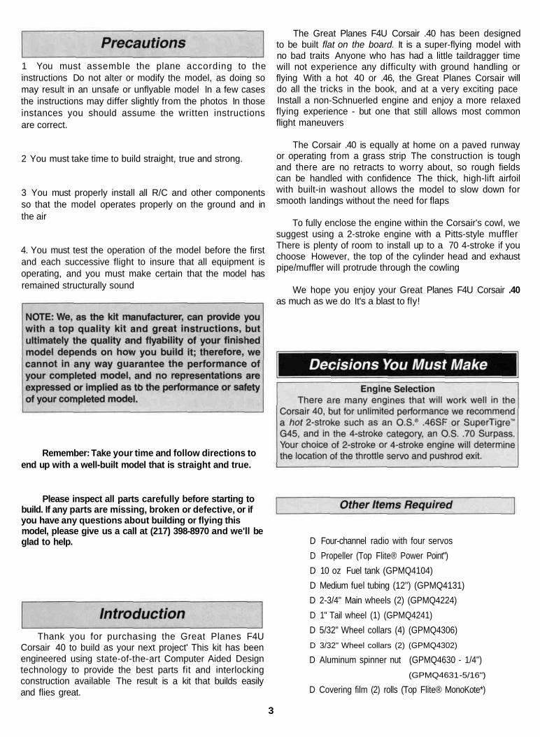
D Four-channel radio with four servosD Propeller (Top Flite® Power Point")D 10 oz Fuel tank (GPMQ4104)D Medium fuel tubing (12") (GPMQ4131)D 2-3/4" Main wheels (2) (GPMQ4224)D 1" Tail wheel (1) (GPMQ4241)D 5/32" Wheel collars (4) (GPMQ4306)D 3/32" Wheel collars (2) (GPMQ4302)
D Aluminum spinner nut (GPMQ4630 - 1/4")(GPMQ4631 -5/16")
D Covering film (2) rolls (Top Flite® MonoKote*)
3

D 2-1/2" Pilot figure (Williams Bros #176)*D 1/4" Latex Foam Rubber Padding (HCAQ1000)D Easy Fueler" fuel filling valve (GPMQ4160)*D Switch and Charge Jack (GPMM1000)*D Paint for cowl (Top Flite®LustreKote" paint)D Engine 40 - 46 2-stroke
48- 70 4-stroke
*These items are suggested optional items to dress up yourCorsair 40
On our workbench, we have three 11" Great PlanesEasy-Touch Bar Sanders equipped with #80, #150 and#220-gnt sandpaper This setup is all that is required foralmost any sanding task Custom sanding blocks can bemade from balsa for sanding hard to reach spots We alsokeep some #320-gnt wet-or-dry sandpaper handy for finishsanding before covering
We recommended Great Planes Pro" CA and EpoxyD 2 oz Pro CA (thin GPMR6003)D 2 oz Pro CA+ (medium GPMR6009)D 1 oz Pro CA-(thick GPMR6014)D 6-Minute Pro Epoxy (GPMR6045)D 30-Minute Pro Epoxy (GPMR6047)D 4oz Pro Wood Glue (GPMR6161)D Hand or electric drillD Sealing iron (TOPR2100)D Hotsock(TOPR2175)D Heat gun (TOPR2000)D Hobby saw (X-Acto" razor saw)D Hobby knife, #11 BladesD Razor plane (Master Airscrew*)D PliersD Screw drivers (Phillips and flat tip)D Round file (or similar)D T-pins (HCAQ5150)D StringD Straightedge with scaleD Masking tape (required for construction)D Sandpaper (coarse medium, fine grit)*D Easy-Touch Bar Sander (or similar)D Waxed paperD Lightweight balsa filler such as Hobbico* HobbyLite"
(Hobbico #HCAR3400)D 1/4-20 Tap and tap wrenchD IsopropyI rubbing alcohol (70%)D Auto body filler (Bondo* or similar)
Great Planes Easy-Touch Bar Sanders are made fromlightweight extruded aluminum and can be found at mosthobby shops They are available in two sizes - 11"(GPMR6170) for most general purpose sanding and 22"(GPMR6172) for long surfaces such as wing leading edgesWe recommend using the 2" wide self-adhesive sandpapersold in 12" rolls by Great Planes Standard sandpaper canbe attached by gluing it to the sander with brush-on rubbercement Apply the rubber cement to both the bottom of thesander and the back of the sandpaper When both surfacesare dry to the touch, press the sandpaper firmly onto thesander Spray adhesive can be used for this purpose but it'smuch harder to remove the sandpaper when you need toreplace it Use a knife blade for cutting sandpaper, not yourgood scissors'
Easy-Touch Sandpaper 12" RollGPMR6180- 80-gntGPMR6183-150-gritGPMR6185-220-grit
Common Abbreviations Used InThis Manual And On The Plans
Drill Bits D 1/16" D 1/8" D 3/16" (Long Bit)D 5/64" D 9/64" LI 13/64"D 3 / 3 2 " D 5 / 3 2 " D 1/4"D 7/64" LI 3/16"
Fuse = FuselageLE = Leading Edge (front)TE = Trailing Edge (rear)Ply = PlywoodStab = Stabilizer" = Inchesmm = Milimeters
4

Inches x 25.4 = mm (conversion factor)
1/64" = .4 mm1/32" = .8 mm1/16" = 1.6mm3/32" = 2.4 mm1/8" = 3.2 mm
5/32" = 4.0 mm
3/16" = 4.8 mm1/4" = 6.4 mm3/8" = 9.5 mm1/2" = 12.7mm5/8" = 15.9mm3/4" = 19.0mm
1" = 25.4 mm2" = 50.8 mm3" = 76.2 mm6" = 152.4mm
12" = 304.8mm18" = 457.2mm
21" = 533.4 mm24" = 609.6 mm30" = 762.0 mm36" = 914.4mm
Inch Scale
0 10 20 30 40 50 60 70 80 90 100 110 120 130 140 150 160 170 180Metric Scale
Balsa Basswood Plywood
Get Ready To BuildD 1 Unroll the plan sheets. Reroll the plans inside out tomake them lie flat
D 2. Remove all parts from the box. As you do, figure outthe name of each part by comparing it with the plans andthe parts list included with this kit Most part numbers startwith CRS4 This identifies the kit The numbers followingCRS4 identify the part Using a felt-tip or ballpoint pen,lightly write the part name or size on each piece to avoidconfusion later Use the die-cut patterns shown on page 6to identify the die-cut parts and mark them before removingthem from the sheet Save all scraps If any of the die-cutparts are difficult to remove, do not force them' Instead, cutaround the parts with a hobby knife After removing the die-cut parts, use your Easy-Touch Bar Sander or sandingblock to lightly sand the edges to remove any die-cuttingirregularities.
D 3 As you identify and mark the parts, separate them intogroups, such as fuse (fuselage), wing, fin, stab (stabilizer)and hardware.
5

6

Work over waxed paper covered plans, on a flat worksurface. Refer to the plans to identify the parts andtheir locations.
D 1. Locate the shaped 1/4" balsa forward (S01) and aftstab (S02) parts. Check their fit and sand the mating edgesas needed. Mark a centerline on both parts. Align thecenterlines on the stab parts with the centerline on theplans. Glue the two parts together with a thin bead ofmedium CA. Wipe off any excess from the surface beforeit cures.
D 5. Locate the shaped 1/4" balsa balance tabs (S09),rudder front (S07) and rudder rear (S08) parts. Checktheir fit and sand the mating edges as needed. Glue thethree parts together with a thin bead of thin CA. Wipe offany excess from the surface before it cures.
D 6. Sand the joints of the elevators and rudder smoothwith sharp 220-grit sandpaper and a sanding block.
D 7. Tape the two shaped 1/4" balsa elevators in positionon the TE of the stab. Center the bent elevator joiner wire(WBNT101) over the elevators as shown, then mark thelocation of the "arms."
D 2. Locate the shaped 1/4" balsa fin front (S05) and finrear (S06) parts. Check their fit and sand the mating edgesas needed. Glue the two parts together with a thin bead ofmedium CA. Wipe off any excess from the surface beforeit cures.
D 3. Sand the joints of both assemblies smooth with sharp220-grit sandpaper and a sanding block.
D 4. Locate the shaped 1/4" balsa elevators (S03) andbalance tabs (S04). Check their fit and sand the matingedges as needed. Glue the balance tabs to the elevatorswith a thin bead of medium CA. Wipe off any excess fromthe surface before it cures.
D 8. Carefully draw a centerline around the edges of bothelevators. Drill a 1/8" diameter pilot hole into the LE of eachelevator (on the centerline) at the marked location. Redrillthe holes with a 9/64" bit. The holes must be at least1-1/8" deep.
D 9. Cut a 1/8" deep groove in the elevator LE between theinside (root) edge and the hole you drilled (see the "ExpertTip" on page 8). Insert the joiner wire. Adjust the depth ofthe groove until the joiner wire is flush with the LE.
7

D 10. Test fit the joiner wire into both elevators. Make surethat both elevators are flat on the work surface and that thetips of the elevators align with the tips of the stab.
Lt 1. Locate the 1/8" die-cut ply (W02A) and the two 1/16"die-cut birch ply (W02B) wing center spars. Use 30-minute epoxy to glue the 1/16" die-cut birch ply center sparto the front and back of the 1/8" die-cut ply center spar.Make sure that all three center spars are perfectlyaligned. Wipe off any excess epoxy with alcohol and apaper towel.
D 11. Draw a line 1" from the TE on both sides of theelevators. Carefully sand a taper from this line to the TE.Remove equal amounts of balsa from each side of theelevator until the TE is 1/8" thick.
D 12. Taper the TE of the rudder using the same procedureas used for the elevators.
D 2. Lay out the 3/32" die-cut wing ribs R-5 (W04) and the1/8" die-cut wing ribs R-3 (W08) exactly as shown in thephoto. Position the 1/16" die-cut birch ply doublers R-3Band R-5B (W01) on each rib as shown. By so doing we willbe making a right and a left pair. Use 30-minute epoxy toglue the doublers to the ribs. Make sure that the doublersare perfectly aligned with the ribs.
D 13. Sand the LE of the elevators and rudder to a "V"shape as shown on the plans. Sand a radius on the LE andtip ends of the stab and fin. Leave the TE of the stab and finsquared off.
D 3. Locate the 1/8" die-cut ribs R-1 (W07) and the 1/8"die-cut ply doublers R-1B (F01). Use 30-minute epoxy toglue ribs R-1 together. Then, use epoxy to glue ribs R-1between the rib doublers R-1B. Make sure that all fourpieces are perfectly aligned. Wipe off any excess epoxywith alcohol and a paper towel.
8

D 4. Pin the wing center spar over the plans perpendicularto the building board. Fit the R-1 rib assembly in thecenter spar. Place the center jig (W10) under the TE ofthe rib assembly. Glue the rib assembly perpendicular tothe center spar using thin CA.
D 5. Fit the 1/8" die-cut rib R-2 (W07) on the center spar.Locate the 1/8" die-cut ply dihedral gauge (F01). Oneedge of the gauge is angled to set the dihedral of the wing,the other edge is 90° to the bottom of the gauge. Use the90° edge to align the ribs R-2 perpendicular to the centerspar. Pin the TE of the ribs on the center Jig. Glue ribs R-2perpendicular to the center spar using thin CA.
D 6. The shaped and notched wing leading edges (W12)and sub-trailing edges (W12) are fastened together bythin strips of balsa. Separate them by cutting with a hobbyknife, as shown in the sketch above.
D 7. Cut a 4-3/8" long piece of LE and sub TE. Fit the LE,then the sub TE to the ribs. The LE must be centeredvertically on each rib. The sub TE should be flush with thetop and bottom of the ribs. Glue ribs R-1 and R-2 to the LEand sub TE. Do not glue the sub TE to the center jig.
D 8. Sand the ends of the LE and sub TE flush with ribs R-2.
D 9. Use a 3/32" drill bit to drill the wing mounting dowelhole through the LE. The best way to line up the drill withthe slot in ribs R-1 is to sight down the LE from the side.Use a 1/4" drill to enlarge the hole while makingadjustments to the alignment.
D 10. Chamfer both ends of the 1/4" x 3-1/2" hardwoodwing dowel (DOWLS030). Test fit the dowel (without glue)into the LE and ribs R-1. The fit should be snug, so don'tenlarge the slot any more than necessary. When satisfiedwith the fit, remove the wing dowel and set it aside forlater use.
9

D 11. Slide ribs R-5 onto the center spar so that the plydoubler R-5B is toward rib R-2. Align rib R-5 over the plan.Make sure that the TE of ribs R-2 are seated on the centerjig and the jig tabs on ribs R-5 are against the buildingboard. Use the rib gauge (5G) (F02) to check the angle ofR-5. Then, glue the ribs perpendicular to the center sparwith medium CA.
D 12. Fit ribs R-3 and the 3/32" die-cut ribs R-4 (W08) intothe center spar. The ply doubler R-3B on rib R-3 is towardrib R-4. Do not glue the ribs to the center spar. Cut two 6"long pieces, one from each LE and sub TE. Trim one end ofthe LE so that it fits flush against the LE at rib R-2 and iscentered vertically on the front of rib R-5. Glue the LE inplace with medium CA. Trim one end of the sub TE so thatit fits flush against the sub TE at rib R-2 and is flush withthe top and bottom of rib R-5. Glue the sub TE to rib R-5and the TE at rib R-2 with medium CA. Repeat this processfor the other side.
D 1. Lightly sand the top of the ribs flush with the centerspar. Cut a 4-1/2" long piece from a 3/32" x 4" x 30" balsaLE sheet (W13) to fit between ribs R-2. Sand a bevel onthe front edge of the sheet. Test fit the LE sheet in position.Trim the back edge flush with the back of the center spar.When satisfied with the fit, press the forward edge of thesheet tightly against the LE and the ribs, then wick thin CAalong the forward seam. Wipe off any excess CA before itcures. Apply a bead of thick CA on the top of ribs R-1 andR-2. Roll the sheet into contact with the ribs and the centerspar. Wick thin CA between the sheet and the center spar.
D 13. Locate the 1/8" die-cut ply dihedral gauge (F01). Oneedge of the gauge is angled to set the dihedral of the wing.The other edge is 90° to the bottom of the gauge. Use the90° edge of the dihedral gauge to align ribs R-3 and R-4perpendicular to the center spar. Check that the LE iscentered vertically on the ribs and the sub TE is flush with thetop and bottom of the ribs. Glue the ribs to the LE and sub TEwith thin CA and to the center spar with medium CA.
D 2. Refer to the photo above, then use a razor saw orhobby knife to finish cutting the partially die-cut aileronservo opening in ribs R-1.
D 3. Cut two 3/4" long pieces from the 1/4" x 1/2" x 6" balsahatch mounting block (W16). Glue the 1/4" edge of thetwo pieces flush with the top of the center spar and ribs R-2 with thin CA. Use medium CA to glue the remaining1/4" x 1/2" mounting block in the slots die-cut in ribs. Trimthe mounting block flush with ribs R-2.
10
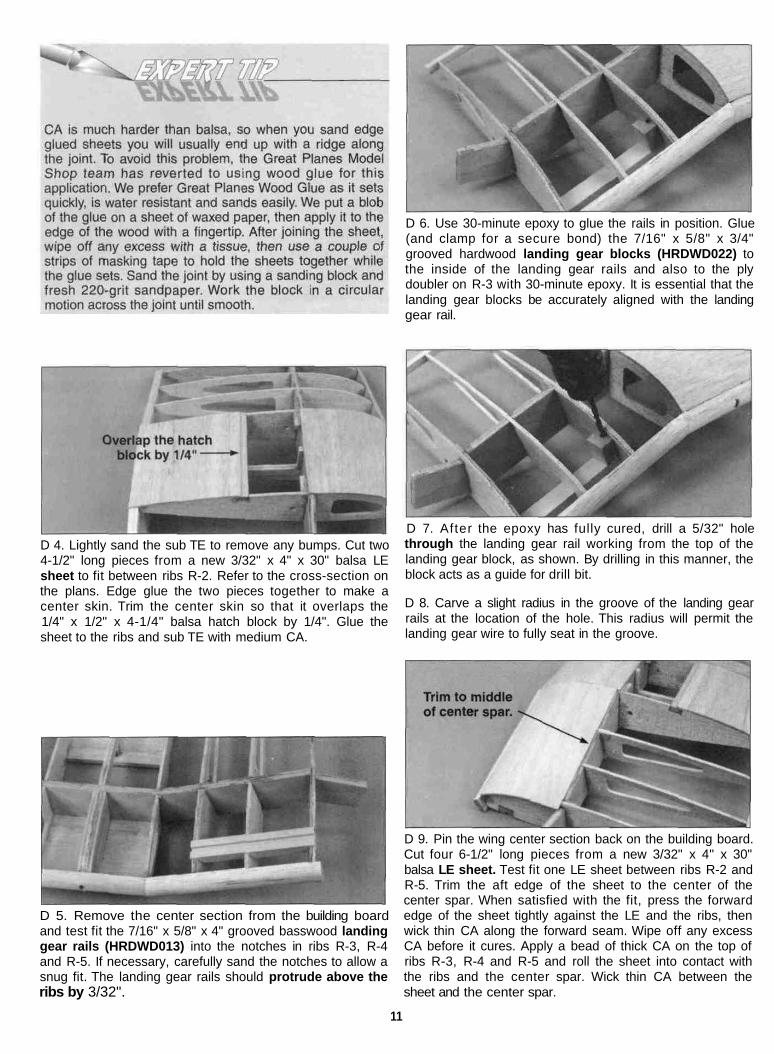
D 6. Use 30-minute epoxy to glue the rails in position. Glue(and clamp for a secure bond) the 7/16" x 5/8" x 3/4"grooved hardwood landing gear blocks (HRDWD022) tothe inside of the landing gear rails and also to the plydoubler on R-3 with 30-minute epoxy. It is essential that thelanding gear blocks be accurately aligned with the landinggear rail.
D 4. Lightly sand the sub TE to remove any bumps. Cut two4-1/2" long pieces from a new 3/32" x 4" x 30" balsa LEsheet to fit between ribs R-2. Refer to the cross-section onthe plans. Edge glue the two pieces together to make acenter skin. Trim the center skin so that it overlaps the1/4" x 1/2" x 4-1/4" balsa hatch block by 1/4". Glue thesheet to the ribs and sub TE with medium CA.
D 7. After the epoxy has fully cured, drill a 5/32" holethrough the landing gear rail working from the top of thelanding gear block, as shown. By drilling in this manner, theblock acts as a guide for drill bit.
D 8. Carve a slight radius in the groove of the landing gearrails at the location of the hole. This radius will permit thelanding gear wire to fully seat in the groove.
D 5. Remove the center section from the building boardand test fit the 7/16" x 5/8" x 4" grooved basswood landinggear rails (HRDWD013) into the notches in ribs R-3, R-4and R-5. If necessary, carefully sand the notches to allow asnug fit. The landing gear rails should protrude above theribs by 3/32".
D 9. Pin the wing center section back on the building board.Cut four 6-1/2" long pieces from a new 3/32" x 4" x 30"balsa LE sheet. Test fit one LE sheet between ribs R-2 andR-5. Trim the aft edge of the sheet to the center of thecenter spar. When satisfied with the fit, press the forwardedge of the sheet tightly against the LE and the ribs, thenwick thin CA along the forward seam. Wipe off any excessCA before it cures. Apply a bead of thick CA on the top ofribs R-3, R-4 and R-5 and roll the sheet into contact withthe ribs and the center spar. Wick thin CA between thesheet and the center spar.
11
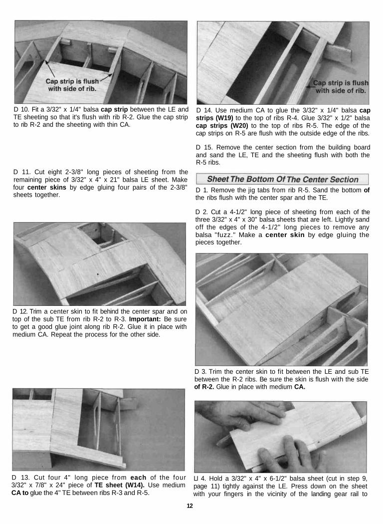
D 10. Fit a 3/32" x 1/4" balsa cap strip between the LE andTE sheeting so that it's flush with rib R-2. Glue the cap stripto rib R-2 and the sheeting with thin CA.
D 14. Use medium CA to glue the 3/32" x 1/4" balsa capstrips (W19) to the top of ribs R-4. Glue 3/32" x 1/2" balsacap strips (W20) to the top of ribs R-5. The edge of thecap strips on R-5 are flush with the outside edge of the ribs.
D 15. Remove the center section from the building boardand sand the LE, TE and the sheeting flush with both theR-5 ribs.
D 11. Cut eight 2-3/8" long pieces of sheeting from theremaining piece of 3/32" x 4" x 21" balsa LE sheet. Makefour center skins by edge gluing four pairs of the 2-3/8"sheets together.
D 12. Trim a center skin to fit behind the center spar and ontop of the sub TE from rib R-2 to R-3. Important: Be sureto get a good glue joint along rib R-2. Glue it in place withmedium CA. Repeat the process for the other side.
D 1. Remove the jig tabs from rib R-5. Sand the bottom ofthe ribs flush with the center spar and the TE.
D 2. Cut a 4-1/2" long piece of sheeting from each of thethree 3/32" x 4" x 30" balsa sheets that are left. Lightly sandoff the edges of the 4-1/2" long pieces to remove anybalsa "fuzz." Make a center skin by edge gluing thepieces together.
D 3. Trim the center skin to fit between the LE and sub TEbetween the R-2 ribs. Be sure the skin is flush with the sideof R-2. Glue in place with medium CA.
D 13. Cut four 4" long piece from each of the four3/32" x 7/8" x 24" piece of TE sheet (W14). Use mediumCA to glue the 4" TE between ribs R-3 and R-5.
LI 4. Hold a 3/32" x 4" x 6-1/2" balsa sheet (cut in step 9,page 11) tightly against the LE. Press down on the sheetwith your fingers in the vicinity of the landing gear rail to
12

make an impression of the landing gear rail on the inside ofthe sheet. Turn the LE sheet over, then cut the access holefor the landing gear rail using the impression mark as aguide. Trim the aft edge of the sheet to overlap the centerspar halfway.
D 5. Test fit the LE sheet in position. When satisfied withthe fit, press the forward edge of the sheet tightly againstthe LE and the ribs, then wick thin CA along the forwardseam. Wipe off any excess CA before it cures. Gently liftthe aft edge of the sheet and quickly apply a bead ofmedium (or thick) CA to the top of each rib. Press the sheetinto contact with the ribs and hold it there until the CAcures. Wick thin CA along the joint between the sheet, thecenter spar and the landing gear rail. Hold the sheet edgedown while the CA cures. Repeat on the other half of thecenter section.
D 8. Use medium CA to glue the 3/32" x 1/4" balsa capstrips to the top of the R-4 ribs. Glue 3/32" x 1/2" balsa capstrips to the top of the R-5 ribs. The edge of the cap stripson the R-5 ribs must be flush with the side of the ribs.
D 9. Sand the LE and TE sheeting flush with the R-5 ribs.
D 6. From the 2-3/8" wide center skins (cut in step 11, page12) trim the skins to fit between the LE sheeting and thesub TE from ribs R-2 to R-3. Glue them in place withmedium CA.
D 7. Use medium CA to glue previously cut 3/32" x 7/8" x 4"balsa TE sheet to the TE. Refer to the cross-section shownon the plans.
D 1. Sand the TE sheeting flush with the sub TE.
D 2. Cut a 4-1/2" long TE from one of the 1-1/8" x 24"tapered ailerons (W17). From each of the two 1-1/8" x 6-7/8"TE (W18), cut a 5-3/4" piece. The leftover 1-1/8" TE will beused on the outer wing panels. Fit the 4-1/2" long TE on theaft edge of the wing center section. Glue the TE to the aftedge with 6-minute epoxy. Use masking tape to hold it inposition until the epoxy cures. Wipe off any epoxy that maysqueeze out with a paper towel. Bevel the ends of the TE tomatch the angle at the center section. Trim the 5-3/4" TE tofit the outboard sub TE and glue them in position withmedium CA.
13
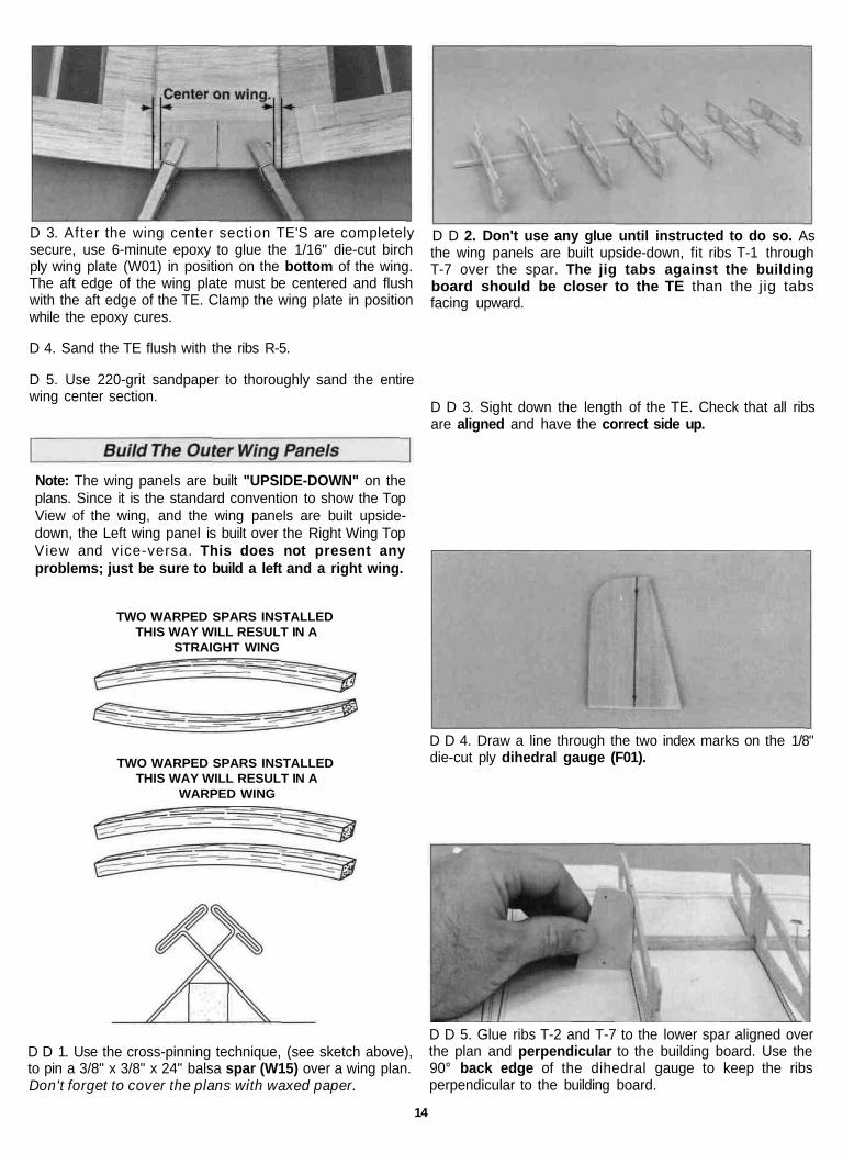
D 3. After the wing center section TE'S are completelysecure, use 6-minute epoxy to glue the 1/16" die-cut birchply wing plate (W01) in position on the bottom of the wing.The aft edge of the wing plate must be centered and flushwith the aft edge of the TE. Clamp the wing plate in positionwhile the epoxy cures.
D 4. Sand the TE flush with the ribs R-5.
D 5. Use 220-grit sandpaper to thoroughly sand the entirewing center section.
D D 2. Don't use any glue until instructed to do so. Asthe wing panels are built upside-down, fit ribs T-1 throughT-7 over the spar. The jig tabs against the buildingboard should be closer to the TE than the jig tabsfacing upward.
D D 3. Sight down the length of the TE. Check that all ribsare aligned and have the correct side up.
Note: The wing panels are built "UPSIDE-DOWN" on theplans. Since it is the standard convention to show the TopView of the wing, and the wing panels are built upside-down, the Left wing panel is built over the Right Wing TopView and vice-versa. This does not present anyproblems; just be sure to build a left and a right wing.
TWO WARPED SPARS INSTALLEDTHIS WAY WILL RESULT IN A
STRAIGHT WING
TWO WARPED SPARS INSTALLEDTHIS WAY WILL RESULT IN A
WARPED WING
D D 4. Draw a line through the two index marks on the 1/8"die-cut ply dihedral gauge (F01).
D D 1. Use the cross-pinning technique, (see sketch above),to pin a 3/8" x 3/8" x 24" balsa spar (W15) over a wing plan.Don't forget to cover the plans with waxed paper.
D D 5. Glue ribs T-2 and T-7 to the lower spar aligned overthe plan and perpendicular to the building board. Use the90° back edge of the dihedral gauge to keep the ribsperpendicular to the building board.
14
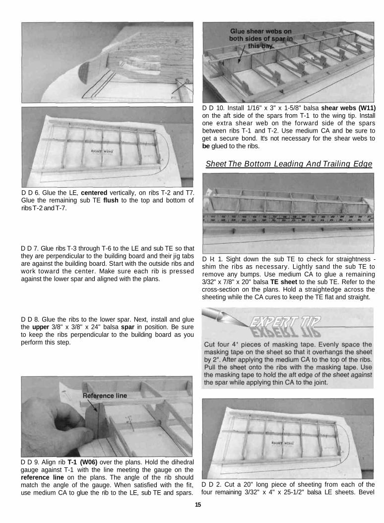
D D 6. Glue the LE, centered vertically, on ribs T-2 and T7.Glue the remaining sub TE flush to the top and bottom ofribs T-2 and T-7.
D D 7. Glue ribs T-3 through T-6 to the LE and sub TE so thatthey are perpendicular to the building board and their jig tabsare against the building board. Start with the outside ribs andwork toward the center. Make sure each rib is pressedagainst the lower spar and aligned with the plans.
D D 8. Glue the ribs to the lower spar. Next, install and gluethe upper 3/8" x 3/8" x 24" balsa spar in position. Be sureto keep the ribs perpendicular to the building board as youperform this step.
D D 9. Align rib T-1 (W06) over the plans. Hold the dihedralgauge against T-1 with the line meeting the gauge on thereference line on the plans. The angle of the rib shouldmatch the angle of the gauge. When satisfied with the fit,use medium CA to glue the rib to the LE, sub TE and spars.
D D 10. Install 1/16" x 3" x 1-5/8" balsa shear webs (W11)on the aft side of the spars from T-1 to the wing tip. Installone extra shear web on the forward side of the sparsbetween ribs T-1 and T-2. Use medium CA and be sure toget a secure bond. It's not necessary for the shear webs tobe glued to the ribs.
Sheet The Bottom Leading And Trailing Edge
D l-t 1. Sight down the sub TE to check for straightness -shim the ribs as necessary. Lightly sand the sub TE toremove any bumps. Use medium CA to glue a remaining3/32" x 7/8" x 20" balsa TE sheet to the sub TE. Refer to thecross-section on the plans. Hold a straightedge across thesheeting while the CA cures to keep the TE flat and straight.
D D 2. Cut a 20" long piece of sheeting from each of thefour remaining 3/32" x 4" x 25-1/2" balsa LE sheets. Bevel
15
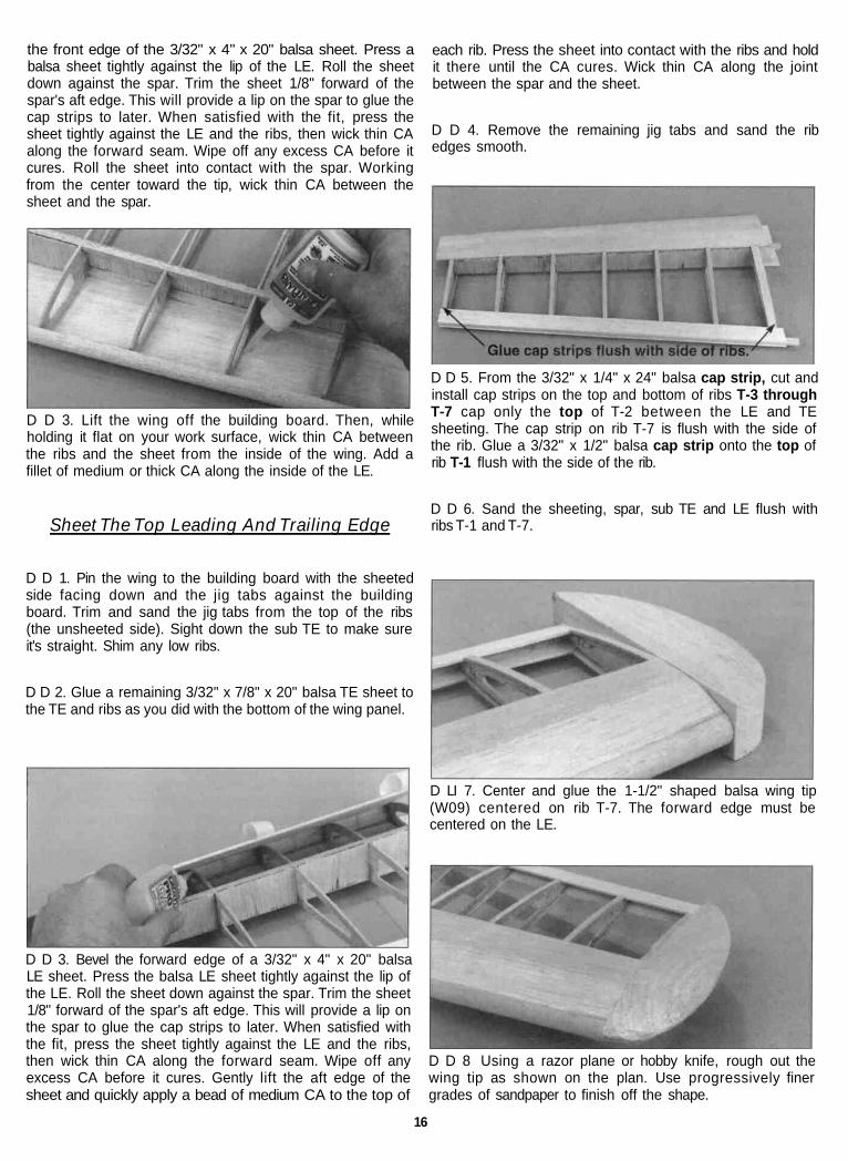
the front edge of the 3/32" x 4" x 20" balsa sheet. Press abalsa sheet tightly against the lip of the LE. Roll the sheetdown against the spar. Trim the sheet 1/8" forward of thespar's aft edge. This will provide a lip on the spar to glue thecap strips to later. When satisfied with the fit, press thesheet tightly against the LE and the ribs, then wick thin CAalong the forward seam. Wipe off any excess CA before itcures. Roll the sheet into contact with the spar. Workingfrom the center toward the tip, wick thin CA between thesheet and the spar.
D D 3. Lift the wing off the building board. Then, whileholding it flat on your work surface, wick thin CA betweenthe ribs and the sheet from the inside of the wing. Add afillet of medium or thick CA along the inside of the LE.
each rib. Press the sheet into contact with the ribs and holdit there until the CA cures. Wick thin CA along the jointbetween the spar and the sheet.
D D 4. Remove the remaining jig tabs and sand the ribedges smooth.
D D 5. From the 3/32" x 1/4" x 24" balsa cap strip, cut andinstall cap strips on the top and bottom of ribs T-3 throughT-7 cap only the top of T-2 between the LE and TEsheeting. The cap strip on rib T-7 is flush with the side ofthe rib. Glue a 3/32" x 1/2" balsa cap strip onto the top ofrib T-1 flush with the side of the rib.
Sheet The Top Leading And Trailing EdgeD D 6. Sand the sheeting, spar, sub TE and LE flush withribs T-1 and T-7.
D D 1. Pin the wing to the building board with the sheetedside facing down and the jig tabs against the buildingboard. Trim and sand the jig tabs from the top of the ribs(the unsheeted side). Sight down the sub TE to make sureit's straight. Shim any low ribs.
D D 2. Glue a remaining 3/32" x 7/8" x 20" balsa TE sheet tothe TE and ribs as you did with the bottom of the wing panel.
D D 3. Bevel the forward edge of a 3/32" x 4" x 20" balsaLE sheet. Press the balsa LE sheet tightly against the lip ofthe LE. Roll the sheet down against the spar. Trim the sheet1/8" forward of the spar's aft edge. This will provide a lip onthe spar to glue the cap strips to later. When satisfied withthe fit, press the sheet tightly against the LE and the ribs,then wick thin CA along the forward seam. Wipe off anyexcess CA before it cures. Gently lift the aft edge of thesheet and quickly apply a bead of medium CA to the top of
D LI 7. Center and glue the 1-1/2" shaped balsa wing tip(W09) centered on rib T-7. The forward edge must becentered on the LE.
D D 8 Using a razor plane or hobby knife, rough out thewing tip as shown on the plan. Use progressively finergrades of sandpaper to finish off the shape.
16
D D 9. Cut the access slot between the spars in T-1 for thewing center spar.
D 3. Sand one end of the remaining 1-1/8" x 1" tapered TEto match the angle of the wing center section. Use mediumCA to glue both 1" TE'S in position.
That's one wing panel down. Now, go back and build theother one. Remember to build a right and left outerwing panel.
NOTE: Before actually using any glue, test fit the entireassembly together to make sure the wing panels fitproperly.
D 4. While holding an aileron against the inside edge of thewing panel sub TE, draw a line on it that matches the insideedge of the wing tip TE. Cut the aileron 1/8" shorter thanthe TE opening to allow for covering material.
D 5. Draw a centerline on the forward edge of the aileron.Sand the forward edge of the aileron to a "V". Refer to thecross section of the wing on the plans for the desired angle.
D 1. Cut the 1/8" x 2" hardwood alignment dowel(DOWEL049) in half. Insert 1/2" of the 1/8" x 1" alignmentdowel through the hole at the aft end of R-5. Glue it to theinside of the TE perpendicular to R-5.
D 2. Assemble only one wing panel to the center section ata time. Completely coat the spars and shear webs insidethe access slot with 30-minute epoxy. Use a stick or brushto apply epoxy to rib T-1. Slide the wing panel on the wingcenter spar. Glue the 1/8" alignment dowel to the inside TEof the wing panel. Make sure the panel and center sectionare aligned from the LE to TE, then clamp or tape themtogether until the epoxy cures.
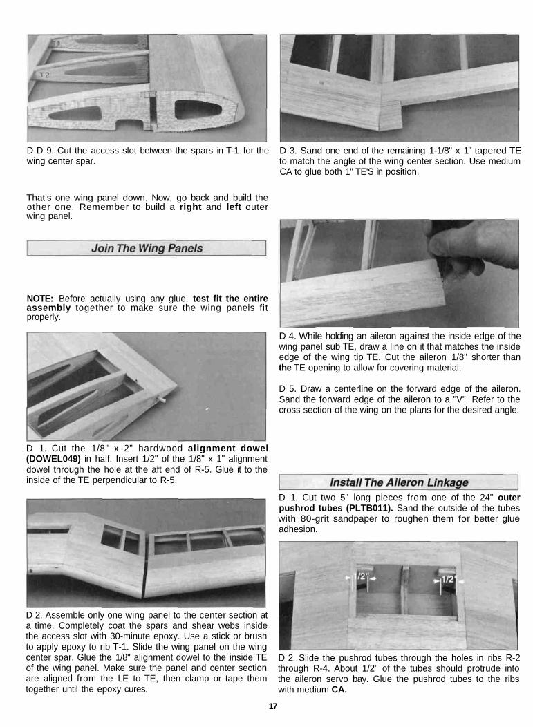
D 1. Cut two 5" long pieces from one of the 24" outerpushrod tubes (PLTB011). Sand the outside of the tubeswith 80-grit sandpaper to roughen them for better glueadhesion.
D 2. Slide the pushrod tubes through the holes in ribs R-2through R-4. About 1/2" of the tubes should protrude intothe aileron servo bay. Glue the pushrod tubes to the ribswith medium CA.
17

Equal distanceD 3. Position the 1/16" die-cut birch ply aileron servohatch (W01) over the aileron servo bay and mark thelocation of the outer pushrod tubes. Position the aileronservo on the hatch positioned so that the servo wheel iscentered in the opening of the hatch and aligned with themarks for the outer pushrod tubes. Use 30-minute epoxy toglue two 5/16" x 3/4" x 7/8" basswood servo mount blocks(P516W28) to the aileron servo hatch.
onto each pushrod, spacing them about 2" apart starting 2"from the threaded end. If the bushings are too loose, put adrop of thin CA on the pushrod at each bushing.
D 8. Attach the clevises to the aileron servo wheel. Insertthe pushrod in the outer pushrod tube located in the aileronservo bay.
D 4. When the epoxy has fully cured, fit a 1/32" to 1/16"temporary shim between the servo and the plywood hatch.Drill 1/16" pilot holes and mount the servo to the blocks.Then remove the shims.
1/2"
1/16" HOLE
D 5. Trim a servo wheel as shown. Then install it onthe servo.
LI 6. Position the aileron servo hatch on the servo bay. Drill1/16" pilot holes through the hatch and hatch blocks at theembossed marks on the hatch. Remove the hatch and placea drop of thin CA in each hole in the hatch blocks. Wipe offthe excess CA and reinstall the hatch. Secure the hatch tothe wing with five #2 x 3/8" sheet metal screws (SCRW024).
D 9. Locate the 1/8" die-cut ply bellcrank supports (F01).Assemble the bellcrank parts on the supports as shownabove making a left and a right. Put a drop of medium CAon the nut and the threads of the 4-40 bolt to prevent thenut from vibrating loose.
D 10. Align the outermost hole in the bellcrank with thepushrod. Use medium CA to glue the bellcrank support torib T-1 and the shear web. Then, apply a fillet of thick CAalong the joint.
3/4"
D 7. Thread two nylon clevises (NYLON17) thirteencomplete turns onto two 2-56 x12" threaded rods(WIRES16). Slide silicone clevis retainers (PLTB021)over the clevises. Cut four 3/16" long bushings from the6-1/2" inner pushrod tube (PLTB004). Slide two bushings
D 11. Attach a solder clevis (METAL030) to the outermosthole in the bellcrank. Align the bellcrank so that it isperpendicular to the pushrod. Cut the pushrod and solderthe clevis on the end of it. Silver solder is highlyrecommended. Reinstall the control rod on the bellcrank.
18

D 12. Use the template on the wing plan to make twobellcrank sheets from the 3/32" scrap balsa LE sheeting.Glue the bellcrank sheet to the LE sheeting and ribs T-1and T-2. Finish covering rib T-1 with a 1/2" cap strip and T-2with a 1/4" cap strip.
D 13. Inspect all the glue joints in the wing and apply CAwhere necessary. Using 220-grit sandpaper, blend the LEinto the LE sheeting.
D 14. Use 6-minute epoxy to glue the wing dowel inperpendicular to the LE.
D 15. Drill two 1/4" holes through the wing center TE usingthe holes in the wing plate for the locations.
Well, that completes the wing construction for now, so cleanup your work bench, grab a cup of coffee, and let's startbuilding the fuse.
Building Notes:
19
Note: All fuse formers must be installed with theirdie-stamped numbers facing forward. This is to ensurecorrect alignment of the pushrod holes and locking tabs.
D 1. Locate both die-cut 3/32" balsa upper fuse sides andlower fuse sides (F05). Glue the upper and lower fusesides together with thin CA. Sand the fuse side smooth with220-grit sandpaper.
D 5. Use 6-minute epoxy to glue the 1/8" die-cut plydoubler C-2 (F02) to the front of the 1/8" die-cut ply formerF-2 (F02). The hole through C-2 must be aligned with thehole through former F-2.
D 2. Place the fuse sides on a flat work surface with thewing saddles facing each other as shown in the photo. Usemedium CA to glue the die-cut 1/8" ply fuse doublers(F01) in position. The edges must be flush, and the 1/8" x1" notch at the forward end of each fuse side must exactlymatch the doublers' notch. Note: Make a right and a leftfuse side. The right side has a slot for the outer pushrodtube exit. Use the pieces from the die-cutting to fill in thepushrod exit slot in the left fuse side.
Note: The formers are stamped only with the necessarypart of their names.
Note: The fuse is built upside-down over the plans. Theplan sheet may be cut apart if space is a problem.
D 3. Cover the bottom view of the fuselage plans withwaxed paper.
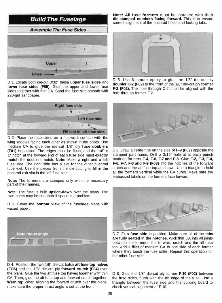
D 6. Draw a centerline on the side of F-9 (F02) opposite thestamped part name. Drill a 3/16" hole at at each punchmark on formers F-4, F-6, F-7 and F-8. Glue F-2, F-3, F-4,F-6, F-7, F-8 and F-9 (F03) into the notches of the forwardcrutch and the aft fuse top as shown. Use a triangle to holdall the formers vertical while the CA cures. Make sure theembossed labels on the formers face forward.
D 7. Fit a fuse side in position. Make sure all of the tabsare fully seated in the notches. Wick thin CA into all jointsbetween the formers, the forward crutch and the aft fusetop. Add a fillet of medium CA to one side of each formerwhere they touch the fuse sides. Repeat this operation forthe other fuse side.
D 4. Position the two 1/8" die-cut balsa aft fuse top halves(FO6) and the 1/8" die-cut ply forward crutch (F04) overthe plans. Glue the two aft fuse top halves together with thinCA. Then, glue the aft fuse top and forward crutch together.Warning: When aligning the forward crutch over the plans,make sure the proper thrust angle is set at the front.
D 8. Glue the 1/8" die-cut ply former F-10 (F02) betweenthe fuse sides, flush with the aft edge of the fuse. Use atriangle between the fuse side and the building board tocheck vertical alignment of F-10.
20
D 9. Glue the 1/8" die-cut ply former F-5 (F03) into thenotches of the fuse doubler.
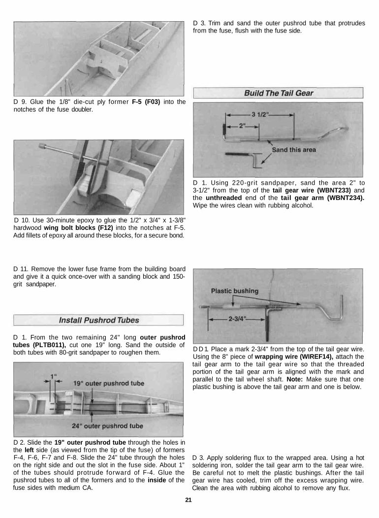
D 3. Trim and sand the outer pushrod tube that protrudesfrom the fuse, flush with the fuse side.
D 1. Using 220-grit sandpaper, sand the area 2" to3-1/2" from the top of the tail gear wire (WBNT233) andthe unthreaded end of the tail gear arm (WBNT234).Wipe the wires clean with rubbing alcohol.
D 10. Use 30-minute epoxy to glue the 1/2" x 3/4" x 1-3/8"hardwood wing bolt blocks (F12) into the notches at F-5.Add fillets of epoxy all around these blocks, for a secure bond.
D 11. Remove the lower fuse frame from the building boardand give it a quick once-over with a sanding block and 150-grit sandpaper.
D 1. From the two remaining 24" long outer pushrodtubes (PLTB011), cut one 19" long. Sand the outside ofboth tubes with 80-grit sandpaper to roughen them. D D 1. Place a mark 2-3/4" from the top of the tail gear wire.
Using the 8" piece of wrapping wire (WIREF14), attach thetail gear arm to the tail gear wire so that the threadedportion of the tail gear arm is aligned with the mark andparallel to the tail wheel shaft. Note: Make sure that oneplastic bushing is above the tail gear arm and one is below.
D 2. Slide the 19" outer pushrod tube through the holes inthe left side (as viewed from the tip of the fuse) of formersF-4, F-6, F-7 and F-8. Slide the 24" tube through the holeson the right side and out the slot in the fuse side. About 1"of the tubes should protrude forward of F-4. Glue thepushrod tubes to all of the formers and to the inside of thefuse sides with medium CA.
D 3. Apply soldering flux to the wrapped area. Using a hotsoldering iron, solder the tail gear arm to the tail gear wire.Be careful not to melt the plastic bushings. After the tailgear wire has cooled, trim off the excess wrapping wire.Clean the area with rubbing alcohol to remove any flux.
21

D 4. Trial f it the tail gear in the fuse. With the plasticbushings aligned with the centerline on the back of F-9, trimthe tail gear arm to allow it to rotate through F-9. Roughenthe bushing with 80-grit sandpaper. Thread a swivel(NYLON20) onto the arm until 1/16" of thread protrudesfrom the swivel. To attach the tail gear to F-9, wrap thelower plastic bushing and F-9 together with a piece ofstring. Make sure the bushing is aligned with the centerlineon F-9. Glue the bushing to F-9 with 6-minute epoxy.
D 7. Use medium CA to glue the 1/4" x 24" balsa trianglesticks (F10) flush to the fuse sides and the bottom of theformers from F-5 through F-10. Sand the triangle sticks andfuse sides flush with F-5 through F-10.
D 5. Screw a swivel clevis (NYLON21) 13 turns onto theend of a 36" wire pushrod (WIRES17). Cut the unthreadedend to shorten the wire to 23-1/2". Cut six 3/16" bushingsfrom the plastic inner pushrod tube provided in the kit. Slidethe bushings on the wire pushrod, spacing them about 3"apart as shown on the plans. If they are too loose, put a dropof thin CA on the pushrod wire at each bushing to securethem in place. Locate the bushings on both ends so thatthey will not exit or snag on the outer pushrod tubes.
D 8. Sheet the bottom of the fuse with a 1/16" x 3" x 30"balsa sheet (F18). The sheeting is applied cross-grain.After the sheeting has been applied, trim and sand thesheeting flush with the fuse sides.
D 6. Slide the wire pushrod into the outer pushrod tube andconnect the clevis swivel to the swivel. Check that the tailgear moves smoothly and that the swivel clevis does notbind on F-9.
D 1. Use 30-minute epoxy to glue the 1/8" die-cut ply F-1Afirewall (F04) and two 1/8" die-cut ply F-1B firewalls (F01)together. Make sure the die-cut punch marks on F-1A are tothe outside.
22

D 2. Test fit the firewall in the fuse. Remove any cured epoxythat may prevent the firewall from seating tight against thefuse sides and fuse doubler. The firewall angles slightly tothe right to compensate for torque. The left side of thefirewall is flush with the front of the fuse side. There is aslight gap between the firewall and the fuse doubler. Cutthree pieces from the 1/2" x 12" triangle stick (F08) to fitbetween the firewall, fuse sides and forward crutch. After youare satisfied with the fit, epoxy the firewall and triangle sticksto the fuse with 30-minute epoxy.
D 3. After the epoxy has cured, sand the fuse sides flushwith the front of the firewall..
D 4. From a 3/16" x 3/16" x 30" balsa stringer (F07), cut andglue a stringer into each notch from the firewall to former F-2.Sand the stringers flush with the firewall and former F-2.
With the sheet pressed against the firewall and former F-2use medium CA to glue one piece to the right fuse sideonly. The joint between the fuse side and the sheeting willbe slightly offset.
D 6. Wet the outside of the sheet with water and let it soakin for a few minutes. Firmly, yet carefully, pull the sheetaround the firewall and mark where it crosses the centerlineof the 3/16" square center stringer. Cut the sheet on the lineyou marked.
D 7. Pull the sheet into position and glue it in place.
D 8. Apply the sheet to the other side in the same manneras described above. Sand the sheeting flush with thefirewall and trim it to match the LE of the wing at thewing saddle.
The Great Planes adjustable engine mount is simple andconvenient to use. It may be used to mount most .40 - .60two-stroke and .40 - .70 four-stroke engines.
D 5. Cut Two 4" long pieces from the 3/32" x 3" x 8-7/8"balsa front lower sheet (F17). Fit the lower sheet so thatthe rear corner is aligned with the LE of the wing saddle.
D 1. Cut or break the "spreader bar" from each mount half.Carefully trim any extra material left by the spreader barfrom each mount half. The surface where the spreader barswere attached must be smooth to allow the mount halves tof i t together. Trim the flashing off any rough edges ifnecessary. Assemble the mount halves as shown.
23

D 2. Draw a centerline on F-1A by connecting the punchmarks on the firewall.
marks on the mount. Tighten the 6-32 screws to hold themount firmly in position against the firewall. Position theengine so that the front of the drive washer will be 4-15/16"in front of the firewall. Mark the engine mounting holes onthe mount. Remove the engine and drill a 7/64" holethrough the beams at each mark. Install the engine with the6-32 x 3/4" sheet metal screws (SCRW018) that havebeen provided with this kit.
D 3. Drill a 11/64" diameter hole at each of the four die-punch marks on F-1A. Then install the mount sidewaysusing four 6-32 x 1" machine screws (SCRW008), #6 flatwashers (WSHR004) and 6-32 blind nuts (NUTS003).Tighten the machine screws all the way to draw the blindnuts into position, then loosen them slightly to allow themount to be adjusted to fit the engine. Secure the blind nutsto the firewall with a drop or two of medium CA around theflange.
Note: When installing an O.S. .70 4-stroke engine, you willneed to remove the choke mechanism in order to positionthe engine far enough back on the mounting rails to achievethe 4-15/16" distance from the firewall.
D 4. Slide the engine mount halves apart until the enginemounting lugs will sit flat on the beams. Adjust the mountuntil the firewall centerline is centered between the "tick"
D 5. Mark the location for the throttle pushrod hole on F-1A.
DI 6. Use a 3/16" drill bit to drill a hole through the firewall atthe throttle hole location you marked in step 5. Cut andinsert an 8" length of remaining outer pushrod tubethrough the firewall. Mark formers F-2 and F-3 where thetube needs to pass through. Drill a 3/16" hole through theformers or cut notches at the marks. Adjust the outerpushrod tube so that it extends 1/4" past the firewall. Gluethe tube in place.
24

D 7. Cut off approximately 1/2" of threads on the 4"threaded rod (WIRES72). Completely screw the threadedrod into one end of the 12" inner pushrod tube(PLTB012). Attach a solder clevis to the throttle arm andinsert the inner pushrod tube into the outer pushrod tube inthe firewall. With 3/4" of inner pushrod tube protruding fromthe outer pushrod tube, bend the threaded rod to clear themuffler. Rotate the throttle arm toward the firewall and markthe location where the threaded rod passes through thesolder clevis. Cut the threaded rod at the mark and solderthe clevis onto it.
We strongly recommend that the engine be removed fromthe engine mount and stored back in its box to prevent dustfrom entering the engine.
D 1. Glue the die-cut ply formers F-2B, F-3B, F-4B, F-6B,F-7B, F-8B and F-9B (F02, F03 and F04) into their notcheson the fuse top. Use a triangle to maintain the verticalalignment of the formers.
D 2. From a piece of 1/8" scrap ply, cut two 1/2" x 3-1/2"servo tray doublers. Glue the doublers on the forward andaft edges of the servo cutout in the forward crutch.
Note: We used a 10 oz. Great Planes Tank (#GPMQ4104)in out prototypes. By using the supplied right angle fuelsupply tube, the fuel tubing can be routed to the top of thefirewall without the risk of kinking the tube. You may alsoroute the fuel tube below the forward crutch to make fishingthe tubes a little easier. The choice is yours.
D 8. Temporarily install the fuel tank. It's much easier to seewhat is happening at this stage of construction. Decidewhere you want the fuel and vent tubes to exit the firewalland mark the locations. Remove the tank and drill two15/64" (or 7/32") fuel tube exit holes through the firewall atthe locations you marked. Before reinstalling the fuel tank,fuelproof the fuel tank compartment. Wrap the fuel tank infoam to prevent fuel foaming from vibration. Reinstall thetank and connect the fuel tubes. Check for kinks and rectifyany problems before proceeding.
D 3. Cut two of the 3/16" x 3/16" x 30" balsa stringers inhalf. Fit the stringers from former F-6B to F-9B and gluethem in place with thin CA. Sand the end of the stringersflush with F-6B and F-9B.
D 4. Cut three 13" long pieces from the remaining3/16" x 3/16" balsa. Install the stringers flush with the frontof the firewall, allowing them to overhang former F-4B.
25

D 5. Slide the 1/8" die-cut ply instrument panel (F03)under the stringers. The top of the instrument panel anglestoward the front of the fuse. Adjust the panel so that it'stight against the stringers but does not bend them. Sandthe bottom of the panel to match the angle of the forwardcrutch. Glue the instrument panel to the stringers andforward crutch. Then, sand the stringers flush with theinstrument panel.
D 6. Glue the 3/32" x 3-1/4" x 15" balsa front decksheeting (F15) to the front upper deck following the sameprocedure used for sheeting the forward bottom. Allow thesheeting to overhang the instrument panel into the cockpitby 1/2".
D 8. Trim the turtle deck sheet so that it overhangs formerF-6B by 1" and F-9B by 1/8". Glue the sheet to the fusesides, formers F-6B through F-9B and the stringers. Repeatthe process on the other side.
D 9. Trim and sand the turtle deck sheeting and stringersflush with the top of formers. Sand the aft edge of thesheetina flush with F-9B.
D 10. From a 3/32" piece of scrap balsa cut a 1" wide pieceto fit between the turtle deck sheet and the forwarddeck sheet.
D 7 Cut the two 3/32" x 3" x 18" balsa sheets (F14) asshown in the photo above. Glue the small piece to the otherend to make a turtle deck sheet 4" wide at one endand 2" wide at the other. Sand the joint smooth with220-grit sandpaper.
D 11. Glue the 1/2" x 2" x 12" balsa turtle deck block(F19) centered on top of formers F-6B and F-7B and flushwith the front of former F-8B.
26
D 12. Insert the fin in the slots in formers F-8B and F-9B.Glue the 1/2" x 7/8" x 3-7/16" balsa filler block (F20) oneach side of the fin. Do not glue the blocks to the fin. Aftergluing the blocks in position, remove the fin and sand theaft ends of the blocks flush with F-9B.
D 13. Use epoxy to glue the top plastic tail gear bushing,centered on former F-9B just below the slot for the fin.
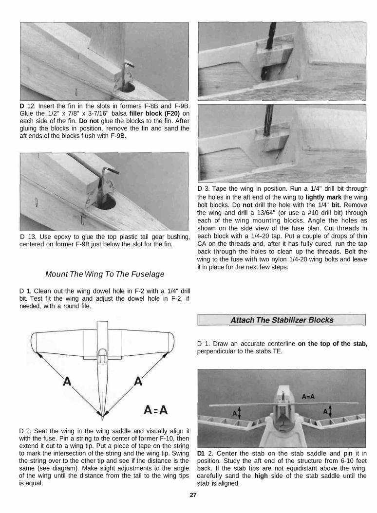
D 3. Tape the wing in position. Run a 1/4" drill bit throughthe holes in the aft end of the wing to lightly mark the wingbolt blocks. Do not drill the hole with the 1/4" bit. Removethe wing and drill a 13/64" (or use a #10 drill bit) througheach of the wing mounting blocks. Angle the holes asshown on the side view of the fuse plan. Cut threads ineach block with a 1/4-20 tap. Put a couple of drops of thinCA on the threads and, after it has fully cured, run the tapback through the holes to clean up the threads. Bolt thewing to the fuse with two nylon 1/4-20 wing bolts and leaveit in place for the next few steps.
Mount The Wing To The Fuselage
D 1. Clean out the wing dowel hole in F-2 with a 1/4" drillbit. Test fit the wing and adjust the dowel hole in F-2, ifneeded, with a round file.
D 2. Seat the wing in the wing saddle and visually align itwith the fuse. Pin a string to the center of former F-10, thenextend it out to a wing tip. Put a piece of tape on the stringto mark the intersection of the string and the wing tip. Swingthe string over to the other tip and see if the distance is thesame (see diagram). Make slight adjustments to the angleof the wing until the distance from the tail to the wing tipsis equal.
D 1. Draw an accurate centerline on the top of the stab,perpendicular to the stabs TE.
D1 2. Center the stab on the stab saddle and pin it inposition. Study the aft end of the structure from 6-10 feetback. If the stab tips are not equidistant above the wing,carefully sand the high side of the stab saddle until thestab is aligned.
27

D 3. Cut two 1/4" long pieces from the 1/4" x 1/4" x 7"balsa stick (F11). Glue each 1/4" piece in front of the stab,slightly overhanging the fuse side.
D 7. Sand the front and bottom of the stab blocks to matchthe angle of the turtle deck. Glue the stab blocks to the1/4" x 1/4" sticks on the stab saddle. Sand the stab blocksand 1/4" x 1/4" sticks so that the 1/2" x 2" x 6-1/2" balsa stabtop block (F22) can be aligned with the turtle deck block.
C1 4. Center the stabilizer using the centerline you drew instep #1. Measure the distance from each stab tip to a pincentered at the nose.
D 5. Cut the remaining 1/4" balsa stick in half and glueeach piece to the fuse at the aft edge of the stab, slightlyoverhanging the fuse side. Be careful not to glue the stab tothe stab saddle. Remove the stab and sand the 1/4" balsasticks flush with former F-10.
D 8. Cut a 1/8" groove on the forward end of the stab topblock for the tail gear. Glue the stab top block onto the stabblocks and to the aft end of the turtle deck block. Sand theaft end of the stab top block flush with former F-10.
D 9. Glue the 3/4" x 1-1/4" x 1-3/4" balsa tail block (F23)flush with the bottom of former F-10.
D 6. Draw a line connecting two corners of the 1/4" x 7/8" x 5"balsa stab fairing block (F21). Cut the block in half diagonally.
D 10. It's time to get out your carving knife or razor planeand Easy-Touch Sander with 80-grit sandpaper. Carve andsand the turtle deck and tail block to shape as shown onthe plans. Blend the fuse sides and the top and bottomsheeting together.
28

D 11. Now is a good time to apply balsa filler to any gaps injoints. This will allow you to finish sand most of the fusebefore installing the fin and stab.
D 12. Trim the canopy with a scissors using the embossedcut lines for reference.
D 13. The top deck sheeting overlaps the instrument panelby 1/4". Use T-pins to locate the instrument panel and drawa line 1/4" behind them. Cut the 1/2" turtle deck block flushwith former F-6B. Center the canopy over the cockpit andmark the outline. Now, move the canopy approximately 1/4"in the direction of where the cut will be made and mark theoutline again. By cutting the balsa on the inside line, a 1/4"border will be left to mount the canopy.
D 1. Reinstall the wing on the fuse. Cut a notch for theelevator joiner wire at the aft end of the slot for the stab.Install the joiner wire in the notch. Then slide the stab intothe stab cradle. Check that the stab is still parallel to thewing and that the stab tips are an equal distance from thenose of the fuse. Lightly draw lines on the top and thebottom of the stab at the joint between the stab and fuse.Remove the stab and apply 30-minute epoxy to both sidesof the stab between the lines. Slide the stab into positionand check its alignment. Wipe off the excess epoxy withalcohol and a paper towel and allow the epoxy to cure.
D 2. Position the fin in the slot in the turtle deck. Hold atriangle on the stab and close to the fin. Check that the finis perpendicular to the stab. Glue the fin in the slot with6-minute epoxy.
D 3. Test fit the elevators on the stabilizer and sand asnecessary to clear the fuse sides.
D 14. Now that the balsa filler has had a chance to dry,finish sand the tail section area. Check all the joints aroundthe balsa blocks and sheeting. If any have come loose orwere missed during the building process, glue them beforefinish sanding with 320-grit sandpaper.
Note: We recommend that the stab and fin be installed atthis point in the construction process. By installing themnow, a small fillet can be made at the joint between thefuse, stab and fin. However, to make covering the fuseeasier, the stab and fin can be installed after everythingis covered.
D 4. Make sure that the tail gear moves freely whileapplying upward pressure. Hold the rudder up to the fin andmark the tail gear "arm" location on the rudder LE. Drill a7/64" hole 7/8" deep at this spot.
29
D 5. Cut a groove from the tail gear hole to the bottom endof the rudder to allow the rudder to fit tightly against the fin.
D 6. To easily make a fillet along the stab and fin, place apiece of masking tape 1/4" on both sides of the joint. Applybalsa filler to the joint using your f inger. Remove themasking tape. Then wet your finger and wipe across thefillet to smooth it out. After the filler has dried lightly, sandthe fillet with 320-grit sandpaper.
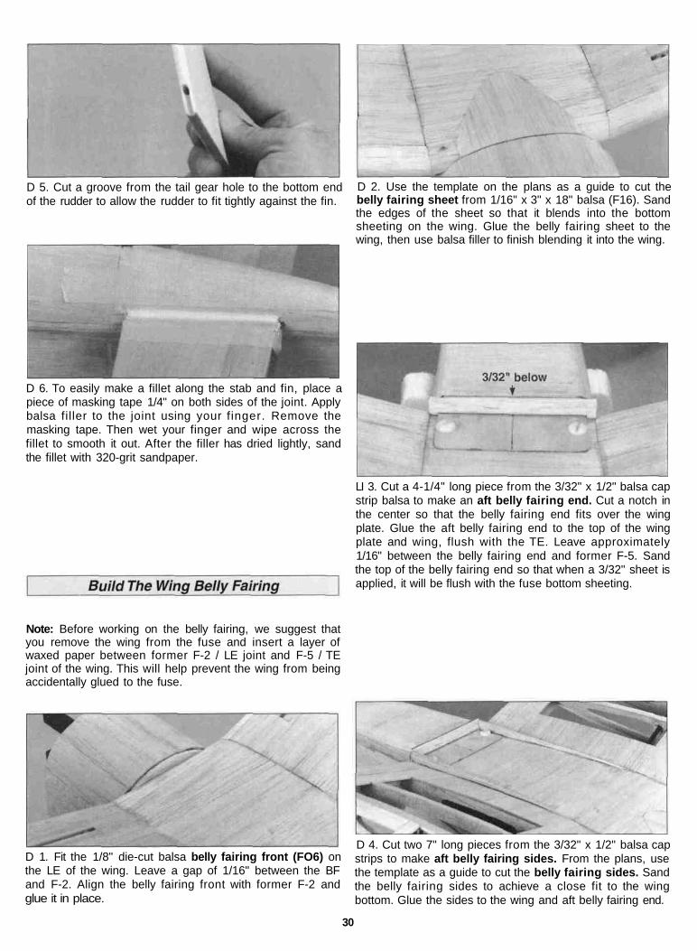
D 2. Use the template on the plans as a guide to cut thebelly fairing sheet from 1/16" x 3" x 18" balsa (F16). Sandthe edges of the sheet so that it blends into the bottomsheeting on the wing. Glue the belly fairing sheet to thewing, then use balsa filler to finish blending it into the wing.
LI 3. Cut a 4-1/4" long piece from the 3/32" x 1/2" balsa capstrip balsa to make an aft belly fairing end. Cut a notch inthe center so that the belly fairing end fits over the wingplate. Glue the aft belly fairing end to the top of the wingplate and wing, flush with the TE. Leave approximately1/16" between the belly fairing end and former F-5. Sandthe top of the belly fairing end so that when a 3/32" sheet isapplied, it will be flush with the fuse bottom sheeting.
Note: Before working on the belly fairing, we suggest thatyou remove the wing from the fuse and insert a layer ofwaxed paper between former F-2 / LE joint and F-5 / TEjoint of the wing. This will help prevent the wing from beingaccidentally glued to the fuse.
D 1. Fit the 1/8" die-cut balsa belly fairing front (FO6) onthe LE of the wing. Leave a gap of 1/16" between the BFand F-2. Align the belly fairing front with former F-2 andglue it in place.
D 4. Cut two 7" long pieces from the 3/32" x 1/2" balsa capstrips to make aft belly fairing sides. From the plans, usethe template as a guide to cut the belly fairing sides. Sandthe belly fairing sides to achieve a close fit to the wingbottom. Glue the sides to the wing and aft belly fairing end.
30
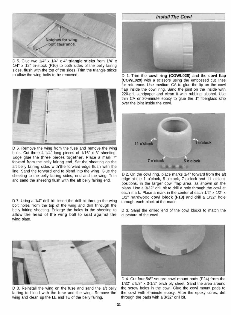
D 5. Glue two 1/4" x 1/4" x 4" triangle sticks from 1/4" x1/4" x 12" tri-stock (F10) to both sides of the belly fairingsides, flush with the top of the sides. Trim the triangle sticksto allow the wing bolts to be removed.
D 6. Remove the wing from the fuse and remove the wingbolts. Cut three 4-1/4" long pieces of 1/16" x 3" sheeting.Edge glue the three pieces together. Place a mark 7"forward from the belly fairing end. Set the sheeting on theaft belly fairing sides with'the forward edge flush with theline. Sand the forward end to blend into the wing. Glue thesheeting to the belly fairing sides, end and the wing. Trimand sand the sheeting flush with the aft belly fairing end.
D 7. Using a 1/4" drill bit, insert the drill bit through the wingbolt holes from the top of the wing and drill through thebelly fairing sheeting. Enlarge the holes in the sheeting toallow the head of the wing bolt to seat against thewing plate.
D 1. Trim the cowl ring (COWL028) and the cowl flap(COWL029) with a scissors using the embossed cut linesfor reference. Use medium CA to glue the lip on the cowlflap inside the cowl ring. Sand the joint on the inside with220-grit sandpaper and clean it with rubbing alcohol. Usethin CA or 30-minute epoxy to glue the 1" fiberglass stripover the joint inside the cowl.
D 2. On the cowl ring, place marks 1/4" forward from the aftedge at the 1 o'clock, 5 o'clock, 7 o'clock and 11 o'clockpositions, in the larger cowl flap area, as shown on theplans. Use a 3/32" drill bit to drill a hole through the cowl ateach mark. Place a mark in the center of each 1/2" x 1/2" x1/2" hardwood cowl block (F13) and drill a 1/32" holethrough each block at the mark.
D 3. Sand the drilled end of the cowl blocks to match thecurvature of the cowl.
D 8. Reinstall the wing on the fuse and sand the aft bellyfairing to blend with the fuse and the wing. Remove thewing and clean up the LE and TE of the belly fairing.
D 4. Cut four 5/8" square cowl mount pads (F24) from the1/32" x 5/8" x 3-1/2" birch ply sheet. Sand the area aroundthe screw holes in the cowl. Glue the cowl mount pads tothe cowl with 6-minute epoxy. After the epoxy cures, drillthrough the pads with a 3/32" drill bit.
31

D 5. Attach the cowl blocks to inside of the cowl using#2 x 3/8" sheet metal screws.
D 6. Stand the fuse up on its tail. Center the cowl on thefuse and mark the cowl block locations on the firewall. Usethe marks to help locate the cowl blocks on the firewall andglue the cowl blocks to the firewall with 6-minute epoxy.
D 1. Fill any scuffs, dings and the forward end of thepushrod tube exit slot with balsa filler. After the filler hashardened, sand the entire structure with progressively finergrades of sandpaper, ending with 320-grit.
D 7. Remove the cowl and install Hie muffler. Cut a piece ofclear butyrate or thin card stock to use as a template (notincluded) long enough to cover the engine. Tape thetemplate to the fuse and with a marker draw the outline ofany part that will protrude out of the cowl (for example, theneedle valve, glow plug and muffler). Trim the area frominside the lines on the template. Test fit the template overthe engine and trim as needed. Carefully remove theengine without disturbing the template and reinstall thecowl. With the template still taped to the fuse, lay thetemplate on the cowl and mark the location where holes willneed to be cut. Remove the cowl and trim out the openings.
D 8. Reinstall the engine on the engine mount and trial fitthe cowl over the engine. Allow approximately 1/16" ofclearance around the muffler for cooling.
Fuelproofing may be done either before or after covering.
D 1. Fuelproof the engine compartment paying specialattention to the firewall. Top Flite LustreKote paint or30-minute epoxy is recommended.
D 2. Fuelproof any external exposed wood.
SPECIAL NOTE: Do not confuse this procedure with"checking the C.G." or "balancing the airplane fore andaft." That very important step will be covered later inthe manual.
Now that you have the basic airframe nearly completed,this is a good time to balance the airplane laterally(side-to-side). Here is how to do it:
D 1. Temporarily attach the wing and engine (with muffler)to the fuselage.
D 2. With the wing level, lift the model by the enginepropeller shaft and the fin post (this may require twopeople). Do this several times.
D 3. If one wing always drops when you lift the model, itmeans that side is heavy. Balance the airplane by gluingweight to the other wing tip.
NOTE: An airplane that has been laterally balanced willtrack better in loops and other maneuvers.
32

The Corsair 40 does not require much painting toobtain the scheme shown, on the box, as most of the finishis done with Top Flite MonoKote Film The only paintingrequired is for the cowl and canopy frame
The technique we will describe here is the how themodel pictured on the box was finished Make sure thestructure is smoothly sanded with 320-grit sandpaperRemove all dust from the structure with a Top Flite TackCloth so the MonoKote will stick well
Cover the aircraft with MonoKote using the followingsequence Make sure the MonoKote is thoroughly stuckdown to the structure and all of the edges are sealed Use aTop Flite MonoKote Hot Sock" on your covering iron toavoid scratching the MonoKote Film.
COVERING TECHNIQUE
You can practically eliminate covering wrinkles thatsometimes occur when the model is left out in the sun orin the back of your car by following this technique used inthe Great Planes model shopA Cover your sealing iron with a Top Flite Hot Sock andturn the heat about 3/4 of the way to the high settingB Cut a piece of MonoKote film about 2" larger all aroundthan the surface you are covering Strip off the backingand position the film Tack the film down smack dab inthe middle of the surface.C Pull (as in stretch) the film toward one end, sealing it tothe balsa from the center out to the tip Work out anywrinkles and air pockets as you proceed with acombination of circular and back and forth motionD. Do the same procedure working the oppositedirection from the centerE Pull and seal diagonally toward the four corners,always starting from the center The trick is to shrink outany wrinkles before you seal the film to the surfaceF Use a heat gun to heat and to stretch the film aroundcurved surfaces like the stab and rudder tips, while pullingon the excess material You may need to pull hard to getout all of the wrinkles, so wear a glove if you need toFollow-up the heat gun with your sealing iron to securethe bondThe idea behind this approach (which can be applied toany part of the model) is to prestretch the MonoKotefilm as it's applied, and remove the air pockets that canexpand later to cause the sags and wrinkles
When covering areas that involve sharp junctions, likethe tail section, cut narrow strips (1/4" to 3/8") and applythem in the corners before covering the major surfacesThe larger pieces of MonoKote Film will overlap andcapture these smaller pieces This technique also bypassesthe need to cut the MonoKote Film in these areas after ithas been applied DO NOT, under any circumstances,attempt to cut the covering material after it has beenapplied to the fin and stab, except around the leadingand trailing edges and the tip. Modelers who do this oftencut through the covering and part-way into the balsa stabThis can weaken the stab to the point where it may failin flight!
1. Tail Junction Strips2. Rudder left and right side3 Bottom of elevators4. Top of elevators5 Stab bottom6 Stab top7. Fin left and right side8. Fuse bottom9. Fuse sides
10 Fuse top (May require three pieces one on each sideand a small triangular piece on the top)
11. Ends of ailerons12. Bottom of ailerons13. Top of ailerons14. TE surfaces of wing and belly fairing15 Junction strips between wing panels16 Bottom of left outer wing panel17 Bottom of right outer wing panel18 Bottom of Left and Right inner wing panels19. Sides and bottom of belly fairing20. Top of left outer wing panel21. Top of right outer wing panel22 Top of left and right inner wing panels.23 Top of center section24. Front and back of landing gear doors
Paint used on the prototype: We used Top Flite LustreKoteInsignia Blue to paint the cowl and canopy frame
First wet sand the cowl with 400-gnt sandpaper to provide arough surface for the paint to adhere to Wash and dry thecowl thoroughly On the canopy, mask the area not to bepainted Roughen the area to be painted with 000 steelwool or 400-gnt sandpaper Clean the area thoroughly withalcohol and a paper towelTo spray the cowl with LustreKote paint First spray a lightcoat on the inside and outside Let the paint flash off (dry)for about two minutes Then, spray a wet coat on (a wetcoat will look slightly rough when first sprayed, but willsmooth out after a couple of seconds) Be careful not to getthe paint on so heavy that it runs For best results, allow thepaint to dry for two or more hours Then spray another wetcoat Allow the paint to dry overnight before installing thecowl on the fuse
To spray the canopy with LustreKote Paint Make sure themasking is down around the edges Spray light coats ofpaint Allow the paint to dry for 5 minutes between coats.After the desired coverage is obtained, remove the maskand allow the paint to dry overnight.
33

We have found that it's much simpler to do all hinging andcontrol horn installation after the model is covered.
D 1. Cut the hinge slots in the stab and elevators using thetechnique described in the Expert Tip section followingthese four steps Test fit the elevators to the stab with thejoiner wire in position When satisfied with the fit, removethe elevators Pack the joiner wire holes in the elevatorswith 30-minute epoxy Then install the elevators on the stabMake sure that both elevators are parallel with each otherUse a paper towel dampened with rubbing alcohol toremove any excess epoxy that squeezes out.
D 1. Cut the hinge slot using a #11 blade in a standard #1knife handle The CA hinges provided have a thicknessthat fits this type of slot very well Trial fit the hinge intothe slot. If the hinge does not slide in easily, work theknife blade back and forth in the slot a few times toprovide more clearance (it is really the back edge of theblade that does the work here in widening the slot).
D 2 Install the rudder following the same procedure usedto install the elevators
D 3. Install the ailerons on the wing, using four hingeseach.
D 4 After the epoxy has cured, CA the hinges in the controlsurfaces.
Note: Refer to the fuse plan for the hinge makinginstructions. Cut 16 hinges from the 2" x 9" suppliedmaterial
D Drill a 3/32" hole, 1/2" deep, in the center of thehinge slot. If you use a Dremel Moto-Tool for this task, itwill result in a cleaner hole than if you use a slowerspeed power or hand drill Drilling the hole will twist someof the wood fibers into the slot, making it difficult to insertthe hinge, so you should reinsert the knife blade, workingit back and forth a few times to clean out the slot.
C. Trial fit the hinges into the slots and temporarily attachthe control surface to verify the fit and operation
The hinge material supplied in this kit consists ofa 3-layer lamination of mylar and polyester It is speciallymade for the purpose of hinging model airplane controlsurfaces Properly installed, this type of hinge providesthe best combination of strength, durability and ease ofinstallation We trust even our best show models to thesehinges, but it is essential to install them correctly.Please read the following instructions and follow themcarefully to obtain the best results These instructionsmay be used to effectively install any of the variousbrands of CA hinges.
The most common mistake made by modelers wheninstalling this type of hinge is not applying a sufficientamount of glue to fully secure the hinge over its entiresurface area, or, the hinge slots are very tight, restrictingthe flow of CA to the back of the hinges This results inhinges that are only "tack glued" approximately 1/8" to1/4" into the hinge slots The following technique hasbeen developed to help ensure thorough andsecure gluing.
D Rather than just making a single slit, it is better to cutaway a narrow rectangle of covering to provide anadequate opening for the CA glue to wick into the slot.
E Insert the hinges and install the control surface Verifythe left-right positioning of the control surface, and closeup the hinge gap to 1/32" or less It is best to leave a veryslight hinge gap, rather than closing it up tight, to helpprevent the CA from wicking along the hinge line Makesure the control surface will deflect to the recommendedthrows without binding If you have cut your hinge slotstoo deep, the hinges may slide in too far, leaving only asmall portion of the hinge in the control surface To avoidthis, you may insert a small pin through the center ofeach hinge, before installing This pin will keep the hingecentered while installing the control surface Remove thepins before proceeding
34

ASSEMBLE, THEN APPLY 6 DROPSOF THIN CA TO CENTER
OF HINGE, ON BOTH SIDES
F. Apply 6 drops of thin CA adhesive to both sidesof each hinge, allowing a few seconds between dropsfor the CA to wick into the slot. Note that the small"tunnels" you created by drilling the 3/32" holes allow theCA to freely travel in to the entire surface of the hinge,producing an extremely secure bond.
THE CA WICKS ALONG THE•TUNNELS" TO THE ENTIRE
HINGE SURFACE
D 1. Secure the tail wheel to the tail gear with two 3/32"wheel collars.
D D 2. Seat the landing gear in the groove on the bottom ofthe wing. Secure it with two nylon straps (NYLON36) andfour #2 x 3/8" sheet metal screws per gear.
strap. Attach the gear door to the hump strap with two#4 x 3/8" sheet metal screws (SCRW043) inserted from thefront of the door into the strap. Repeat the process for theother hump strap.
D 4. The landing gear should be positioned as shown in thesketch above, with the wheel under the L.E.
D 5. Paint the inside of the cockpit light gray (your option).Trim and install the instrument panel decal.
D 6. Position the canopy on the fuse as shown on theplans, then lightly trace its edges on the covering with aballpoint pen. Trim about a 1/16" wide strip of covering fromaround the line you just traced. By removing covering thecanopy will adhere better.
D 7. Before installing the canopy you may wish to add a pilotf igure. We added a block of balsa to the bottom of a2-1/2" Williams Bros. Pilot to give the pilot the proper height.
D 8. Clean the inside of the canopy with window cleanerand allow it to dry. Use R/C-56* or 6-minute epoxy to gluethe canopy in position.
Note: You should wrap a flat battery pack with 1/4" foamrubber (HCAQ1000) and install the battery under thefuel tank.
D 1. Mount three servos in the servo tray following themanufacturer's recommendations. Install "cross" style hornson all servos, cutting off the unused arms.
D D 3. Center the landing gear doors on the landing gear.Hold a nylon hump strap (NYLON30) on the back of thegear door and mark the location of the holes in the hump
D 2. Slide a silicone retainer over the "hex" end of a nylonclevis. Screw the clevis 14 turns onto the threaded end of a36" wire pushrod. Cut the unthreaded end to shorten thewire to 28". Cut five 3/16" bushings from the plastic innerpushrod tube provided in the kit. Slide the bushings on thewire pushrod, spacing them about 3" apart as shown on theplans. If they are too loose, put a drop of thin CA on thepushrod wire at each bushing to hold them in place. Locatethe two bushings on both ends so that they will not exitthe pushrod tubes. Trim the backing plate from a nyloncontrol horn, then clip the clevis to the outer hole of thehorn. Make a second pushrod assembly exactly the sameas the first.
35
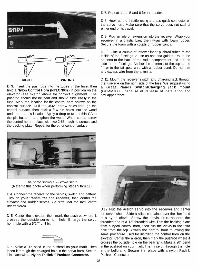
RIGHT WRONG
D 3. Insert the pushrods into the tubes in the fuse, thenhold a Nylon Control Horn (NYLON002) in position on theelevator (see sketch above for correct alignment). Thepushrod should not be bent and should slide easily in thetube. Mark the location for the control horn screws on thecontrol surface. Drill the 3/32" screw holes through thecontrol surface, then prick a few pin holes into the woodunder the horn's location. Apply a drop or two of thin CA tothe pin holes to strengthen the wood. When cured, screwthe control horn in place with two 2-56 machine screws andthe backing plate. Repeat for the other control surface.
D 7. Repeat steps 5 and 6 for the rudder.
D 8. Hook up the throttle using a brass quick connector onthe servo horn. Make sure that the servo does not stall ateither end of its travel.
D 9. Plug an aileron extension into the receiver. Wrap yourreceiver in a plastic bag, then wrap with foam rubber.Secure the foam with a couple of rubber bands.
D 10. Glue a couple of leftover inner pushrod tubes to theinside of the fuselage to use as antenna guides. Route theantenna to the back of the radio compartment and out theside of the fuselage. Anchor the antenna to the top of thefin or to the tail gear wire with a rubber band. Do not trimany excess wire from the antenna.
D 11. Mount the receiver switch and charging jack throughthe fuselage on the right side of the fuse. We suggest usinga Great Planes Switch/Charging jack mount(GPMM1000) because of its ease of installation andtidy appearance.
The photo shows a 2-Stroke setup(Refer to this photo when performing steps 5 thru 11)
D 4. Connect the receiver to the servos, switch and battery.Turn on your transmitter and receiver, then center theelevator and rudder servos. Be sure that the trim leversare centered.
D 5. Center the elevator, then mark the pushrod where itcrosses the outside servo horn hole. Enlarge the servohorn hole with a 5/64" drill bit.
D 6. Make a 90° bend in the pushrod on your mark. Theninsert it through the enlarged hole in the servo horn. Secureit in place with a Nylon Faslink"" Pushrod Connector.
D 12. Plug the aileron servo into the receiver and centerthe servo wheel. Slide a silicone retainer over the "hex" endof a nylon clevis. Screw the clevis 14 turns onto thethreaded end of a 12" threaded wire. Trim the backing platefrom a nylon control horn, then clip the clevis to the thirdhole from the top. Attach the control horn following thesame procedure used for installing the control horn on theelevator. Center the aileron, then mark the pushrod where itcrosses the outside hole on the bellcrank. Make a 90° bendin the pushrod on your mark. Then insert it through the holein the bellcrank. Secure it in place with a nylon FaslinkPushrod Connector.
36

4-CHANNEL RADIO SETUP(STANDARD MODE 2)
ELEVATOR MOVES UP
RIGHT AILERON MOVES UPLEFT AILERON MOVES DOWN
RUDDER MOVES RIGHT
CARBURETOR WIDE OPEN
CONTROL SURFACE THROWS
We recommend the following control surface throws:NOTE: Throws are measured at the widest part of theelevators, rudder and ailerons Adjust the position of thepushrods at the control/servo horns to control the amountof throw.
High Rate Low RateELEVATOR: 1/2" up 5/16" up
5/8" down 3/8" downRUDDER: 1-3/4" right Same
1-3/4" left SameAILERONS: 1/4" up 3/16" up
3/8" down 1/4" downNOTE: If your radio does not have "dual rates," then setup the control surfaces to move between the high rateand low rate throws
NOTE The balance and surface throws for this aircrafthave been extensively tested. We are confident thatthey represent the settings at which the Corsair 40 fliesbest. Please set up your aircraft to the specificationslisted above. If, after a few flights, you would like toadjust the throws to suit your tastes, that's fine. Toomuch throw can force the plane into a stall, soremember, "more is not better."
NOTE: This section is VERY important and must NOTbe omitted! A model that is not properly balanced willbe unstable and possibly unflyable.
D 1. Accurately mark the balance point on the top of thewing on both sides of the fuselage The balance point isshown on the plan (CG), and is located 3-1/2" back fromthe leading edge as shown in the sketch and on the plansHint: Use the full-size fuse plan to help you accuratelylocate the proper balance point This is the balance point atwhich your model should balance for your first flights Later,you may wish to experiment by shifting the balance up to1/4" forward or back to change the flying characteristicsMoving the balance forward may improve the smoothnessand arrow-like tracking, but it may then require more speedfor takeoff and make it more difficult to slow down forlanding Moving the balance aft makes the model moreagile with a lighter and snappier "feel" and often improvesknife-edge capabilities In any case, please start at thelocation we recommend and do not at any time balanceyour model outside the recommended range.
D 2 With the wing attached to the fuselage, all parts of themodel installed (ready to fly) and an empty fuel tank, holdthe model upside-down with the stabilizer level.
D 3 Lift the model at the balance point If the tail dropswhen you lift, the model is "tail heavy" and you must addweight* to the nose to balance it. If the nose drops, it is"nose heavy" and you must add weight* to the tail tobalance it NOTE: Nose weight may be easily installed byusing a "spinner weight" or gluing lead weights into theengine compartment Tail weight may be added by usingGreat Planes (GPMQ4485) "stick-on" lead weights and laterif the balance proves to be OK, you can open the fusebottom and glue these in permanently.
* If possible, first attempt to balance the model by changingthe position of the receiver battery and receiver If you areunable to obtain good balance by doing so, then it w i l l benecessary to add weight to the nose or tail to achieve theproper balance point.
37

Charge the batteriesFollow the battery charging procedures in your radioinstruction manual You should always charge yourtransmitter and receiver batteries the night before yougo flying, and at other times as recommended by theradio manufacturer.
Find a safe place to flyThe best place to fly your R/C model is an AMA
(Academy of Model Aeronautics) chartered club field Askyour hobby shop dealer if there is such a club in your areaand join Club fields are set up for R/C flying and thatmakes your outing safer and more enjoyable The AMA alsocan tell you the name of a club in your area Werecommend that you join AMA and a local club so you canhave a safe place to fly and have insurance to cover you incase of a flying accident (The AMA address is listed onpage 3 of this instruction book)
If a club and its flying site are not available you need tofind a large, grassy area at least 6 miles away from anyother R/C radio operation, like R/C boats and R/C cars andaway from houses, buildings and streets A schoolyard maylook inviting but it is too close to people, power lines andpossible radio interference
Ground check the modelIf you are not thoroughly familiar with the operation of
R/C models, ask an experienced modeler to check to seethat you have the radio installed correctly and that all thecontrol surfaces do what they are supposed to The engineoperation also must be checked and the engine "broken-in"on the ground by running the engine for at least twotanks of fuel Follow the engine manufacturer'srecommendations for break-in. Check to make sure allscrews remain tight, that the hinges are secure and that theprop is on tight.
Range check your radioWherever you do fly, you need to check the operation
of the radio before every time you fly This means with thetransmitter antenna collapsed and the receiver andtransmitter on, you should be able to walk at least 100 feetaway from the model and still have control Have someonehelp you Have them stand by your model and, while youwork the controls, tell you what the various control surfacesare doing
Repeat this test with the engine running at variousspeeds with an assistant holding the model If the controlsurfaces are not always acting correctly, do not fly! Findand correct the problem first
Engine safety precautionsNOTE: Failure to follow these safety precautions mayresult in severe injury to yourself and others.
Keep all engine fuel in a safe place, away from highheat, sparks or flames, as fuel is very flammable Do notsmoke near the engine or fuel, and remember that theengine exhaust gives off a great deal of deadly carbonmonoxide Therefore do not run the engine in a closedroom or garage.
Get help from an experienced pilot when learning tooperate engines
Use safety glasses when starting or running enginesDo not run the engine in an area of loose gravel or
sand, as the propeller may throw such material in your faceor eyes
Keep your face and body as well as all spectators awayfrom the plane of rotation of the propeller as you start andrun the engine
Keep items such as these away from the prop looseclothing, shirt sleeves, ties, scarfs, long hair or looseobjects (pencils, screw drivers) that may fall out of shirt orjacket pockets into the prop
Use a "chicken stick" device or electric starter, followinstructions supplied with the starter or stick Make certainthe glow plug clip or connector is secure so that it will notpop off or otherwise get into the running propeller
Make all engine adjustments from behind therotating propeller
The engine gets hot' Do not touch it during or afteroperation Make sure fuel lines are in good condition so fuelwill not leak onto a hot engine causing a fire
To stop the engine, cut off the fuel supply by closing offthe fuel line or fol low the engine manufacturer'srecommendations Do not use hands, fingers or any bodypart to try to stop the engine Do not throw anything into theprop of a running engine
General1 I will not fly my model aircraft in sanctioned events, airshows, or model flying demonstrations until it has beenproven to be airworthy by having been previouslysuccessfully flight tested
2 I will not fly my model aircraft higher thanapproximately 400 feet within 3 miles of an airport withoutnotifying the airport operator I will give right of way to, andavoid flying in the proximity of full scale aircraft Wherenecessary, an observer shall be used to supervise flying toavoid having models fly in the proximity of full scale aircraft.
3 Where established, I will abide by the safety rules forthe flying site I use, and I will not willfully and deliberatelyf ly my models in a careless, reckless and/ordangerous manner
4 I will not fly my model unless it is identified with myname and address or AMA number, on or in the model
5 I will not operate models with pyrotechnics (any devicethat explodes, burns or propels a projectile of any kind)
Radio control
1. I will have completed a successful radio equipmentground check before the first flight of a new or repaired model.
38

2 I will not fly my model aircraft in the presence ofspectators until I become a qualified flier, unless assistedby an experienced helper.
3. I will perform my initial turn after takeoff away from thepit or spectator areas, and I will not thereafter fly over pit orspectator areas, unless beyond my control.
4. I will operate my model using only radio controlfrequencies current ly allowed by the FederalCommunications Commission
The Great Planes Corsair 40 is a great flying sportairplane that flies smoothly and predictably, yet is highlymaneuverable Compared to other sport planes, its flightcharacteristics are quite docile and forgiving It does not,however, have the self-recovery characteristics of a primaryR/C trainer, therefore, you must either have mastered thebasics of R/C flying or obtained the assistance of acompetent R/C pilot to help you with your first flights
BALANCE THE PROPELLER: Balance your propellerscarefully before flying An unbalanced prop is the singlemost significant cause of damaging vibration Not only willengine mounting screws and bolts vibrate out, possibly withdisastrous effect but vibration will also damage your radioreceiver and battery Vibration will cause your fuel to foam,which will, in turn, cause your engine to run rough or quit
We use a Top Flite Precision Magnetic Prop Balancer(#TOPQ5700) in the workshop and keep a Great PlanesFingertip Balancer (#GPMQ5000) in our flight box.
TAKEOFF: If you have dual rates on your transmitter, setthe switches to "high rate" for takeoff, especially whentaking off in a crosswind Although this model has good lowspeed characteristics, you should always build up as much
speed as your runway will permit before lifting off, as thiswill give you a safety margin in case of a "flame-out" Whenyou first advance the throttle and the tail begins to lift, theplane wil l start to turn left (a character ist ic of all"taildraggers") Be ready for this, and correct by applyingsufficient right rudder to hold it straight down the runwayThe left-turning tendency will go away as soon as the tail isup and the plane picks up speed Be sure to allow the tailto come up Depending on the surface you are flying from,you will need to apply very little to no up elevator until flyingspeed is obtained Don't hold the tail on the ground with toomuch up elevator, as the Corsair will become airborneprematurely and will possibly stall When the plane hassufficient flying speed, lift off by smoothly applying upelevator (don't "jerk" it off to a steep climb'), and climbout gradually
CAUTION (THIS APPLIES TO ALL R/CAIRPLANES) If, while flying, you notice any unusualsounds, such as a low-pitched "buzz," this may be anindication of control surface "flutter" Because fluttercan quickly destroy components of your airplane,any time you detect flutter you must immediately cutthe throttle and land the airplane' Check all servogrommets for deterioration (this will indicate whichsurface f luttered), and make sure all pushrodlinkages are slop-free If it fluttered once, it probablywill flutter again under similar circumstances unlessyou can eliminate the slop or flexing in the linkagesHere are some things which can result in flutterexcessive hinge gap, not mounting control hornssolidly, sloppy fit of clevis pin in horn elasticitypresent in flexible plastic pushrods side-play ofpushrod in guide tube caused by tight bends, sloppyfit of pushrod wire in servo arm, insufficient glueused when gluing in the elevator joiner wire oraileron torque rod, excessive f lexing of aileron,caused by using too soft balsa aileron, excessive"play" or "backlash" in servo gears, and insecureservo mounting
FLYING: We recommend that you take it easy with yourCorsair 40 for the first several flights, gradually "gettingacquainted" with this great sport model as your engine getsfully broken-in Add and practice one maneuver at a time,learning how she behaves in each For ultra-smooth flyingand normal maneuvers, we recommend using the "low rate"settings as listed on page 32 "High rate" elevator may berequired for crisp snap rolls and spins Speed is the key togood knife-edge performance.
LANDING: When it's time to land, fly a normal landingpattern and approach Keep a few clicks of power on untilyou are over the runway threshold For your first landings,plan to land slightly faster than stall speed and on the mainwheels, as this is the easiest way to land your CorsairLater, with a little technique, you will find you can makeslow, 3-point landings.
Have a ball! But always stay in control and fly in asafe manner.
39
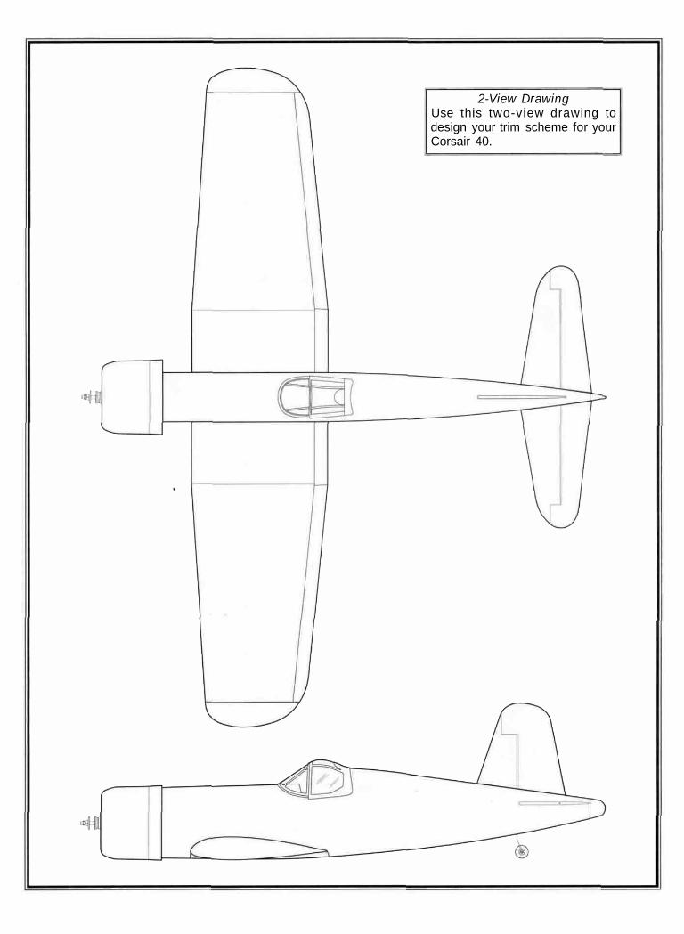
2-View DrawingUse this two-view drawing todesign your trim scheme for yourCorsair 40.