instruction manual - hobbicomanuals.hobbico.com/gpm/gpma0502-manual.pdf · instruction manual...
TRANSCRIPT
INSTRUCTION MANUAL
WARRANTYGreat Planes Model Manufacturing Co. guarantees this kit to be free from defects in both material and
workmanship at the date of purchase. This warranty does not cover any component parts damaged by use ormodification. In no case shall Great Planes' liability exceed the original cost of the purchased kit. Further, GreatPlanes reserves the right to change or modify this warranty without notice.
In that Great Planes has no control over the final assembly or material used for final assembly, no liability shall beassumed nor accepted for any damage resulting from the use by the user of the final user-assembled product. By theact of using the user-assembled product, the user accepts all resulting liability.
If the buyers are not prepared to accept the liability associated with the use of this product, they areadvised to return this kit immediately in new and unused condition to the place of purchase.
P.O. Box 788 Urbana, IL 61801 (217) 398-8970
GAROP04 10/96 V 1 0 Entire Contents © Copyright 1996

Introduction...................................................................3Precautions....................................................................3Decisions You Must Make ............................................3Preparations.................................................................4
Required Accessories..............................................4Building Supplies and Tools.....................................4Optional Supplies and Tools.....................................4Common Abbreviations............................................4Types of Wood .........................................................4Building Notes. . . . ..................................................5Metric Conversions ..................................................5Die-Cut Patterns................................................6 & 7Get Ready to Build...................................................8
Build the Tail Surfaces..................................................8Make the Stabilizer Center.......................................8Build the Stabilizer ...................................................8Build the Elevator...................................................10Build the Fin...........................................................10Build the Rudder.....................................................11Hinge the Tail Surfaces ..........................................12Finish the Tail Surfaces..........................................12
Build the Bottom Wing ...............................................13Bottom Wing Preassembly.....................................13Build the Wing Panels............................................13Sheet the Top of the Wing......................................15Sheet the Bottom of the Wing ................................16Finish the Wing Panel ............................................17Joining the Wing Panels.........................................18Build the Ailerons ...................................................18
Build the Top Wing......................................................19Top Wing Preassembly ..........................................19Build the Wing Panels............................................20Sheet the Bottom of the Wing ................................21Sheet the Top of the Wing......................................22Finish the Wing Panel ...........................................23Joining the Wing Panels.........................................23Joining the Wing Panels.
Build the Fuselage ......................................................25Fuselage Pre-Assembly. .......................................25Assemble the Fuselage Sides................................26Build the Turtledeck................................................30Attach the Bottom Wing .........................................33Attach the Stabilizer and Fin ..................................34Finish the Turtledeck..............................................35Attach the Top Wing........ ......................................35Attach the Aileron Servos and Control Horns. . . . . 36Install the Rudder and Elevator Servos..................37Assemble the Wheel Pants....................................37Assemble the Cowl ................................................38
Covering...........................................................................40Preparing the Surface............................................40Covering Technique ...............................................41Suggested Covering Sequence .............................41
Painting............................................................................41
Final Hookups and Checks.......................................42Install the Hardware ................................................42Attach the Canopy..................................................42
Assemble the N-Struts................................................43Balance the Model Laterally.......................................44Adjustments ................................................................44
Adjusting the Wing .................................................44Make the Aileron Connecting Pushrods.................45
Set the Control Throws...............................................45Balance the Model .................................................46
Preflight..........................................................................46Charge the Batteries ..............................................46Balance the Propeller.............................................46Find a Safe Place to Fly.........................................46Ground Check the Model .......................................47Range Check Your Radio ......................................47Engine Safety Precautions.....................................47
AMA Safety Code ........................................................47General ..................................................................47Radio Control.........................................................48
Flying............................................................................48Takeoff....................................................................48Flight.....................................................................48Landing..................................................................48
Appendix...................................................................49-51Two-View Drawing ........................................Back Cover
Your Giant Aeromaster is not a toy, but rather asophisticated, working model that functions very much likean actual airplane
Because of its realistic performance, the GiantAeromaster, if not assembled and operated correctly,could possibly cause injury to yourself or spectators anddamage property
We recommend that you have at least built and flown a.60 size low wing taildragger before attempting to fly theGiant Aeromaster Even though the Aeromaster is easy tobuild and fly, it will not recover like most trainers. If you arean experianced pilot you will find the Giant Aeromaster areal pleasure to fly
For information on flying clubs in your area you cancontact the national Academy of Model Aeronautics (AMA),which has more than 2,300 chartered clubs acrossthe country.
Contact AMA at the address or toll-free phone number below:Academy of Model Aeronautics
5151 East Memorial DriveMuncie, IN 47302-9252Tele. (800) 435-9262Fax (317) 741-0057
Or via the internet at: http://www.modelaircraft.com
2
Congratulations' Thank you for purchasing the GreatPlanes Giant Aeromaster!
This aircraft is a large scale vesion of the Great Planes60-size Super Aeromaster It's easy to build, extremelyaerobatic and has no "bad habits," making it a greatairplane for hot-dogging Its 73" wingspan makes itInternational Miniature Aircraft Association* (IMAA) legal
*IMAA is an organization that promotes non-competitiveflying of giant scale models.
IMAAInternational Miniature Aircraft Association
205 S Hilldale RoadSalina, KS 67401
5 You must test the operation of the model before everyflight to insure that all equipment is operating, and you mustmake certain that the model has remained structurallysound Be sure to check clevises or other connectors oftenand replace them if they show signs of wear or fatigue
Note: We, as the kit manufacturer, can provide you witha top quality kit and great instructions, but ultimately thequality and flyability of your finished model depends onhow you build it, therefore, we cannot in any wayguarantee the performance of your completed model,and no representations are expressed or implied as tothe performance or safety of your completed model
Remember: Take your time and follow directions toend up with a well-built model that is straightand true.
Please inspect all parts carefully before starting tobuild. If any parts are missing, broken or defective,or if you have any questions about building or flyingthis model, please give us a call at (217) 398-8970and we'll be glad to help.
This is not a beginner's airplane! While theAeromaster is easy to build and flies great, we mustdiscourage you from selecting this kit as your first R/Cairplane It lacks the self-recovery characteristics of goodbasic trainers such as the Great Planes PT" Series Onthe other hand, if you have already learned the basics ofR/C flying, and you are able to safely handle a 60-size lowwing taildragger, the Giant Aeromaster is an excellentchoice to improve your skills and get into giant scale.
Please inspect all parts carefully before starting tobuild! If any parts are missing, broken or defective, or ifyou have any questions about building or flying thismodel, please call us at (217) 398-8970 and we'll beglad to help. If you are calling for replacement parts,please look up the part numbers and the kitidentification number (stamped on the end of thecarton) and have them ready when calling.
1 You must assemble the model according to theinstructions Do not alter or modify the model, as doing somay result in an unsafe or unflyable model In a few casesthe instructions may differ slightly from the photos In thoseinstances the plans and written instructions should beconsidered as correct.
2 Take time to build straight, true and strong.
3 Use an R/C radio system that is in first-class condition,and a correctly-sized engine and components (fuel tank,wheels, etc ) throughout your building process
4. You must properly install all R/C and other componentsso that the model operates properly on the ground and inthe air.
Engine Selection:
The recommended engine size range is as follows:30 - 45cc displacement Glow Engine30 - 60cc displacement Gasoline Engine
We strongly recommend the use of a soft engine mountof some kind, to relieve the stresses on the airframe andradio system, and to make your aircraft quieterJ-Tec and Soundmaster both produce soft mounts forlarge engines.
NOTE: If you are using a gasoline engine, you will needto make sure that your fuel lines and tank are madespecifically to handle gasoline
Radio System Requirements:
The Great Planes Giant Aeromaster requires a minimumof six servos Eight servos are required if you prefer touse a servo for each aileron Our prototype models flewgreat with only six servos
Due to the large scale of this aircraft the GiantAeromaster requires high torque servos to control thesplit elevator (2 required), rudder (1 required) andailerons (2 required) (If you prefer a servo for eachaileron four servos are required.) A standard servo maybe used on the throttle only
On our prototypes we used Y-connectors on the elevatorand aileron servos.
3
Items in parentheses (GPMQ4243) are suggested partnumbers recognized by distributors and hobby shops andare listed for your ordering convenience GPM is the GreatPlanes brand, TOP is the Top Flite brand and HCA is theHobbico brand.
D US Engines" 41cc (USEG0041)D Four-channel radio with six servos
(five high torque and one standard for throttle)D Y-Connector (2)D 24" Servo extension (2)D Propeller (Top Flite Power Point"")D 16 - 24oz Fuel tank of your choiceD Gas or glow fuel tubing depending on fuel usedD 4" Main wheels (2)D 1-1/2" Tail wheel (1) (GPMQ4243)D Covering film (5) rolls (Top Flite MonoKote®)D 3" Pilot figure (WBRQ2626)D 1/4" Latex Foam Rubber Padding (HCAQ1000)D Easy Fueler" fuel fill valve for gas (GPMQ4161)
glow(GPMQ4160)D Switch and Charge Jack (GPMM1000)D Fuelproof paint for cowl and wheel pants
(Top Flite LustreKote paint)D Heavy duty hinges (28)D 3/16" Axle (2)D 3/16" Wheel collars (4) (GPMQ4308)For Mounting the US Engines 41ccStandard mounting system'D 1/4-20 x 1-1/4" Flat Head Bolt (4 req )D 10-32 x 1-1/4" Sockethead Bolt (4 req )D #10 Washer (4 req)D 10-32 Blind Nut (4 req.)Soft mounting systemD J-Tec Snuf-Vibe engine mount (JT-1420SV)D 1/4-20x2" Sockethead bolts (4 required)
These are the building tools that are required Werecommend Great Planes Pro" CA and Epoxy glue
D 2 oz Pro CA (thin, GPMR6003)D 2 oz Pro CA+ (medium GPMR6009)D 1 oz Pro CA- (thick, GPMR6014)D 6-Minute Pro Epoxy (GPMR6045)D 30-Minute Pro Epoxy (GPMR6047)D 4oz Pro Wood Glue (GPMR6161)D Hand or electric drillD Sealing iron (TOPR2100)
D Heat gun (TOPR2000)D Hobby saw (X-Acto razor saw)D Hobby knife #11 BladesD Razor plane (Master Airscrew" 'MASR 1510)D PliersD Screw drivers (Phillips and flat blade)D Tpins(HCAQ5150)D StringD Straightedge with scaleD Masking tape (required for construction)D Sandpaper (coarse medium fine grit)*D Easy-Touch Bar Sander (or similar)*D Wax paperD Balsa filler such as Hobbico" HobbyLite™
(Hobbico #HCAR3400)D 1/4-20 Tap and tap wrenchD IsopropyI rubbing alcohol (70%)D White body putty (Squadron #SQUR1500)D 90° Building squareD Ballpoint penD Felt-tip penD Round fileD Micro balloons (TOPR1090)D Canopy glueDrill bitsD 1 /16" D 1 /8" D 3/16" (Long Bit)D 5/64" D 9/64" D 13/64"D 3/32" D 5/32" D 1/4"D 7 / 6 4 " D 3 / 1 6 "
D CA Applicator Tips (HCAR3780)D Epoxy Brushes (GPMR8060)D Epoxy Mixing Sticks (GPMR8055)D CA Debonder (GPMR6039)D Hot Sock (TOPR2175)D Single edge Razor Blades (HCAR0312)
Elev = Elevator Fuse = FuselageLE = Leading Edge (front) LG = Landing GearLt = Left Ply - PlywoodRt = Right Stab = StabilizerTE = Trailing Edge (rear) " = Inches
Balsa Basswood Plywood4
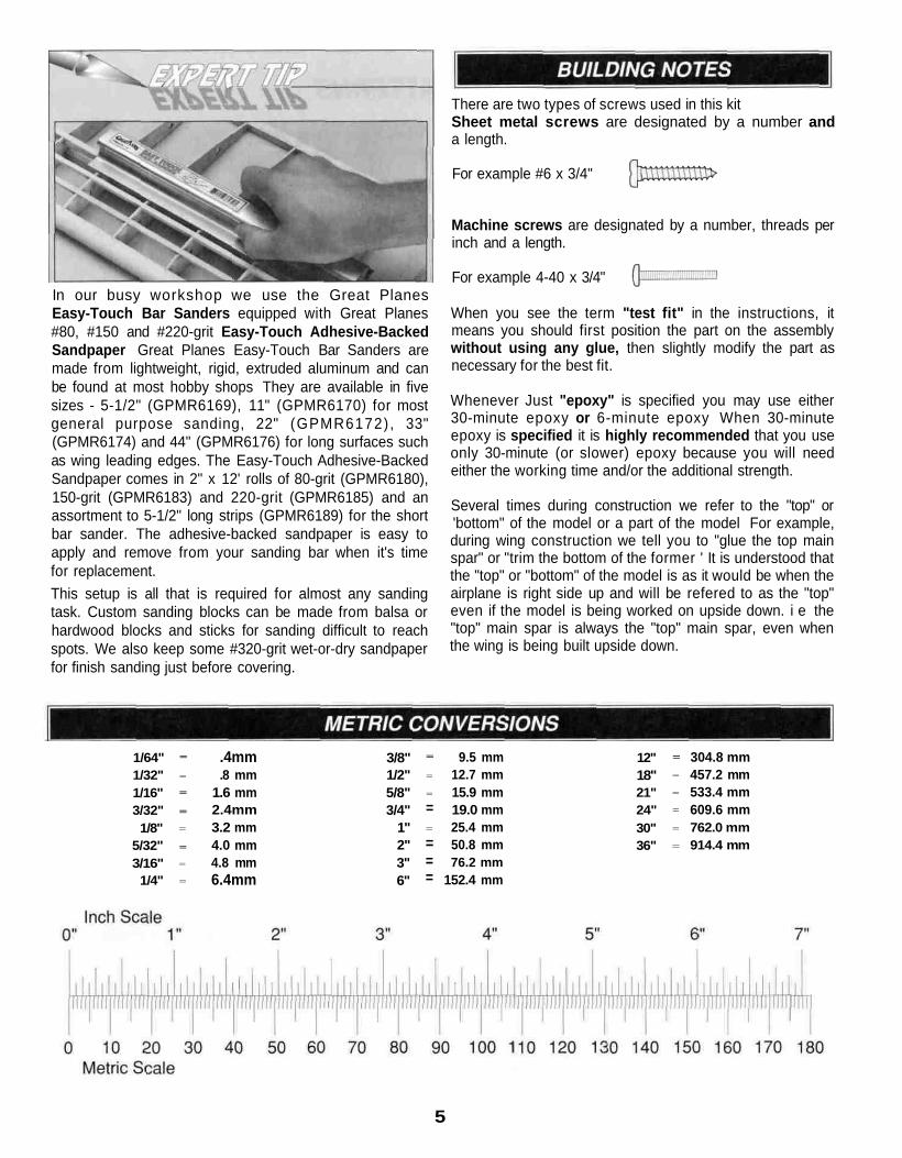
In our busy workshop we use the Great PlanesEasy-Touch Bar Sanders equipped with Great Planes#80, #150 and #220-grit Easy-Touch Adhesive-BackedSandpaper Great Planes Easy-Touch Bar Sanders aremade from lightweight, rigid, extruded aluminum and canbe found at most hobby shops They are available in fivesizes - 5-1/2" (GPMR6169), 11" (GPMR6170) for mostgeneral purpose sanding, 22" (GPMR6172), 33"(GPMR6174) and 44" (GPMR6176) for long surfaces suchas wing leading edges. The Easy-Touch Adhesive-BackedSandpaper comes in 2" x 12' rolls of 80-grit (GPMR6180),150-grit (GPMR6183) and 220-grit (GPMR6185) and anassortment to 5-1/2" long strips (GPMR6189) for the shortbar sander. The adhesive-backed sandpaper is easy toapply and remove from your sanding bar when it's timefor replacement.This setup is all that is required for almost any sandingtask. Custom sanding blocks can be made from balsa orhardwood blocks and sticks for sanding difficult to reachspots. We also keep some #320-grit wet-or-dry sandpaperfor finish sanding just before covering.
There are two types of screws used in this kitSheet metal screws are designated by a number anda length.
For example #6 x 3/4"
Machine screws are designated by a number, threads perinch and a length.
For example 4-40 x 3/4"
When you see the term "test fit" in the instructions, itmeans you should first position the part on the assemblywithout using any glue, then slightly modify the part asnecessary for the best fit.
Whenever Just "epoxy" is specified you may use either30-minute epoxy or 6-minute epoxy When 30-minuteepoxy is specified it is highly recommended that you useonly 30-minute (or slower) epoxy because you will needeither the working time and/or the additional strength.
Several times during construction we refer to the "top" or'bottom" of the model or a part of the model For example,during wing construction we tell you to "glue the top mainspar" or "trim the bottom of the former ' It is understood thatthe "top" or "bottom" of the model is as it would be when theairplane is right side up and will be refered to as the "top"even if the model is being worked on upside down. i e the"top" main spar is always the "top" main spar, even whenthe wing is being built upside down.
1/64"1/32"1/16"3/32"1/8"
5/32"3/16"
1/4"
=
=
=
=
=
=
=
=
.4mm
.8 mm1.6 mm2.4mm3.2 mm4.0 mm4.8 mm6.4mm
3/8"1/2"5/8"3/4"
1"2"3"6"
=
=
=
==
===
9.5 mm12.7 mm15.9 mm19.0 mm25.4 mm50.8 mm76.2 mm
152.4 mm
12"18"21"24"30"36"
=
=
=
==
=
304.8 mm457.2 mm533.4 mm609.6 mm762.0 mm914.4 mm
5
6
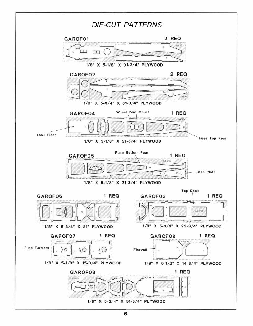
DIE-CUT PATTERNS

7
DIE-CUT PATTERNS
D 1. Unroll the plan sheets. Reroll the plans inside out tomake them lie flat.
D 2. Remove all parts from the box. As you do, determinethe name of each part by comparing it with the plans andthe parts list included with this kit. Using a felt-tip orballpoint pen, lightly write the part name or size on eachpiece to avoid confusion later. Use the die-cut patternsshown on pages 6 & 7 to identify the die-cut parts and markthem before removing them from the sheet. Save allscraps. If any of the die-cut parts are difficult to remove, donot force them! Instead, cut around the parts. Use yourEasy-Touch Bar Sander or sanding block to lightly sand theedges to remove any die-cutting irregularities.
D 3. As you identify and mark the parts, separate theminto groups, such as fuse (fuselage), wing, fin, stab(stabilizer) and hardware. Zipper-top food storage bagsare handy to store your parts as you sort, identify andseparate them into subassemblies.
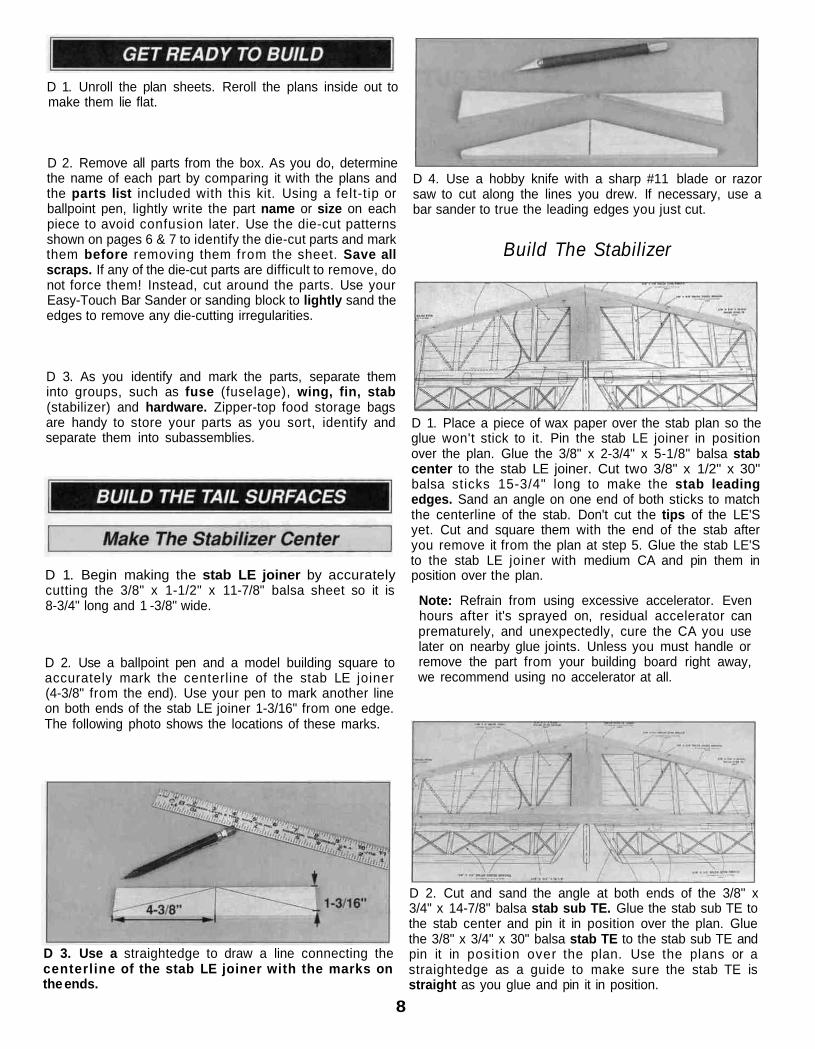
D 1. Begin making the stab LE joiner by accuratelycutting the 3/8" x 1-1/2" x 11-7/8" balsa sheet so it is8-3/4" long and 1 -3/8" wide.
D 2. Use a ballpoint pen and a model building square toaccurately mark the centerline of the stab LE joiner(4-3/8" from the end). Use your pen to mark another lineon both ends of the stab LE joiner 1-3/16" from one edge.The following photo shows the locations of these marks.
D 3. Use a straightedge to draw a line connecting thecenterline of the stab LE joiner with the marks onthe ends.
D 4. Use a hobby knife with a sharp #11 blade or razorsaw to cut along the lines you drew. If necessary, use abar sander to true the leading edges you just cut.
Build The Stabilizer
D 1. Place a piece of wax paper over the stab plan so theglue won't stick to it. Pin the stab LE joiner in positionover the plan. Glue the 3/8" x 2-3/4" x 5-1/8" balsa stabcenter to the stab LE joiner. Cut two 3/8" x 1/2" x 30"balsa sticks 15-3/4" long to make the stab leadingedges. Sand an angle on one end of both sticks to matchthe centerline of the stab. Don't cut the tips of the LE'Syet. Cut and square them with the end of the stab afteryou remove it from the plan at step 5. Glue the stab LE'Sto the stab LE joiner with medium CA and pin them inposition over the plan.
Note: Refrain from using excessive accelerator. Evenhours after it's sprayed on, residual accelerator canprematurely, and unexpectedly, cure the CA you uselater on nearby glue joints. Unless you must handle orremove the part from your building board right away,we recommend using no accelerator at all.
D 2. Cut and sand the angle at both ends of the 3/8" x3/4" x 14-7/8" balsa stab sub TE. Glue the stab sub TE tothe stab center and pin it in position over the plan. Gluethe 3/8" x 3/4" x 30" balsa stab TE to the stab sub TE andpin it in position over the plan. Use the plans or astraightedge as a guide to make sure the stab TE isstraight as you glue and pin it in position.
8
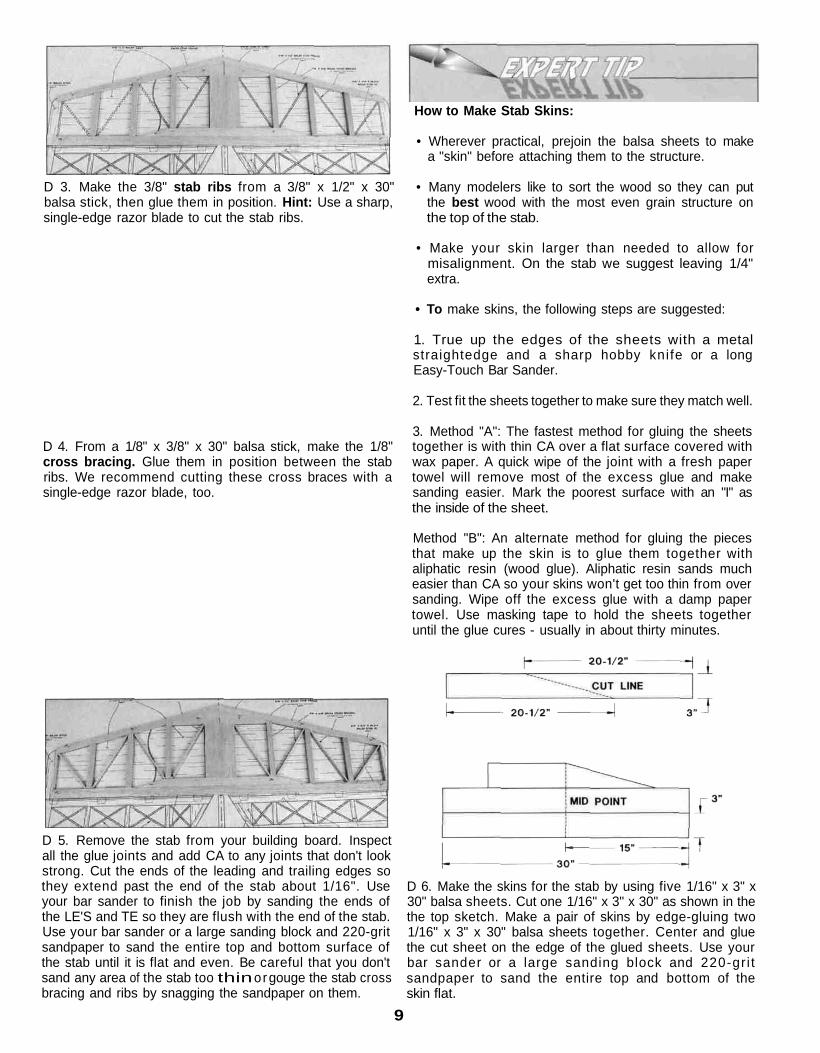
D 3. Make the 3/8" stab ribs from a 3/8" x 1/2" x 30"balsa stick, then glue them in position. Hint: Use a sharp,single-edge razor blade to cut the stab ribs.
D 4. From a 1/8" x 3/8" x 30" balsa stick, make the 1/8"cross bracing. Glue them in position between the stabribs. We recommend cutting these cross braces with asingle-edge razor blade, too.
How to Make Stab Skins:
• Wherever practical, prejoin the balsa sheets to makea "skin" before attaching them to the structure.
• Many modelers like to sort the wood so they can putthe best wood with the most even grain structure onthe top of the stab.
• Make your skin larger than needed to allow formisalignment. On the stab we suggest leaving 1/4"extra.
• To make skins, the following steps are suggested:
1. True up the edges of the sheets with a metalstraightedge and a sharp hobby kni fe or a longEasy-Touch Bar Sander.
2. Test fit the sheets together to make sure they match well.
3. Method "A": The fastest method for gluing the sheetstogether is with thin CA over a flat surface covered withwax paper. A quick wipe of the joint with a fresh papertowel will remove most of the excess glue and makesanding easier. Mark the poorest surface with an "I" asthe inside of the sheet.
Method "B": An alternate method for gluing the piecesthat make up the skin is to glue them together withaliphatic resin (wood glue). Aliphatic resin sands mucheasier than CA so your skins won't get too thin from oversanding. Wipe off the excess glue with a damp papertowel. Use masking tape to hold the sheets togetheruntil the glue cures - usually in about thirty minutes.
D 5. Remove the stab from your building board. Inspectall the glue joints and add CA to any joints that don't lookstrong. Cut the ends of the leading and trailing edges sothey extend past the end of the stab about 1/16". Useyour bar sander to finish the job by sanding the ends ofthe LE'S and TE so they are flush with the end of the stab.Use your bar sander or a large sanding block and 220-gritsandpaper to sand the entire top and bottom surface ofthe stab until it is flat and even. Be careful that you don'tsand any area of the stab too thin or gouge the stab crossbracing and ribs by snagging the sandpaper on them.
D 6. Make the skins for the stab by using five 1/16" x 3" x30" balsa sheets. Cut one 1/16" x 3" x 30" as shown in thethe top sketch. Make a pair of skins by edge-gluing two1/16" x 3" x 30" balsa sheets together. Center and gluethe cut sheet on the edge of the glued sheets. Use yourbar sander or a large sanding block and 220-gr i tsandpaper to sand the entire top and bottom of theskin flat.
9

D 7. Place one of the stab skins on your building board.Apply an even bead of medium or thick CA to one side ofthe stab framework. Place the framework in its properposition on the skin and press it down firmly until the gluehas set. Repeat this step for the other side ofthe stab.
D 8. After the glue has cured, remove the stab from thebuilding board and t r im the sheet ing close to theframework. Use a bar sander or large sanding block and220-grit sandpaper to sand the top and bottom skins flushwith the stab framework. Cut the tips from the 1/2" x 7/8"x 24" balsa stick. Glue the tips onto the end of the staband sand a radius on the corner of the LE.
D D 1. Place a piece of wax paper over the elevator plan.Cut the 1/2" x 7/8" x 24" balsa stick 3-5/8" long to makean elevator tip. Pin the elevator tip to the plan, allowingthe tip to overhang by 1/16" at the LE and TE.
D D 2. Cut a 1/2" x 3/4" x 30" balsa stick in half to makethe elevator leading edge and elevator trailing edge. Usethe plan or a straightedge as a guide to make sure theelevator LE is straight as you glue and pin it in position.
D D 3. Cut and sand the end of the elevator TE to matchthe plan. Again, use the plan or a straightedge as a guideto make sure the elevator TE is straight as you glue andpin it in position.
D D 4. From the 3/8" x 1/2" x 30" balsa stick, cut andglue the elevator root to the LE and TE. Leave anoverhang of 1/16" at the TE. This will be sanded off afterthe elevator is removed from the building board.
D D 5. Make the 3/8" elevator ribs from the 3/8" x 1/2" x30" balsa stick. Then glue them in position. From the 1/2"x 3" x 3-1/2" balsa block, cut the elevator horn block andglue it in position.
D D 6. Make the 1/8" cross bracing from a 1/8" x 1/4" x30" balsa stick. Note that the cross bracing overlaps. Thebottom bracing should be flush with the bottom of theelevator and the top bracing should be flush with the topof the elevator. Glue the cross bracing in position. Werecommend cutting these cross braces with a single-edgerazor blade.
D D 7. Remove the elevator from your building board.Inspect all the glue joints and add CA to any joints thatdon't look strong. Cut the end of the leading edge so thatit extends past the end of the elevator about 1/16". Useyour bar sander to finish the job by sanding the ends ofthe LE and elevator tip so they are flush. On the end ofthe elevator root, sand a radius to match the plan. Sandthe entire top and bottom surface of the elevator until it isflat and even. Be careful that you do not sand anyparticular area of the elevator too thin or gouge theelevator cross bracing and ribs by snagging them onthe sandpaper.
D 8. Go back to step 1 and build the second elevatorfollowing the same procedure.
D 1. Place a piece of wax paper over the fin plan. Cut the3/8" x 3/4" x 24" balsa stick 13-3/4" long to make a fin TE.Pin the fin TE to the plan, allowing the TE to overhang thetop by 1/16". Cut the remaining 3/8" x 3/4" balsa stick9-1/8" long to make a fin TE doubler. Glue the fin TEdoubler to the fin TE so that the top end of the TE doubleris positioned correctly over the plan and the bottom endoverhangs. Cut the second 3/8" x 3/4" x 24" balsa stick tomake the fin LE. Trim one end of the fin LE to the angleshown on the plan and allow the other end to overhangthe top slightly. Use the plan or a straightedge as a guideto make sure the fin TE and LE are straight as you pinthem in position.
10

D 4. Make the skins for the fin by using three 1/16" x 3" x30" balsa sheets. Cut each sheet in half. Make a skin byedge gluing three sheets together. Use your bar sander orlarge sanding block and 220-grit sandpaper to sand theentire top and bottom of the skin flat.
D 2. To make the fin tip, cut the remaining short piece of3/8" x 3/4" balsa stick to fit between the fin LE and TE.When satisfied with the fit, glue the fin tip to the LE andTE. Cut the 3/8" x 3" x 14-7/8" balsa block to make the finLE brace and fin bottom. Cut two notches in the finbottom for the #8x1" screws that secure the stabilizer tothe fuselage. Glue and pin them in position.
D 3. From the 3/8" x 1/2" x 30" balsa stick, make the finribs. Then glue them in position. Remove the fin fromyour building board. Inspect all the glue joints and add CAto any joints that don't look strong. Use your bar sander tosand the top of the LE and TE so they are flush with thefin tip. Sand a radius on the end of the LE to match theplan. Sand the entire top and bottom surface of the finuntil it is flat and even. Be careful that you do not sandany particular area of the fin too thin or gouge the fincross bracing and ribs by snagging them on thesandpaper.
D 5. Pin one of the fin skins down on the building board.Apply an even bead of medium or thick CA to one side ofthe fin framework. Place the framework in its properposition on the skin so that the LE of the fin is flush withthe edge of the 15" balsa sheet and press it down firmlyuntil the glue has cured. Repeat this step for the otherside of the fin. Do not apply the 1/16" skin to the fin post.
D 6. After the glue has cured, remove the fin from thebuilding board. Use your bar sander or a large sandingblock and 220-grit sandpaper to sand the edges of the topand bottom skins flush with the fin framework.
D 1. Place a piece of wax paper over the rudder plan. Cutthe 1/2" x 3/4" x 30" balsa stick 14" long to make a rudderLE. Cut the remaining 1/2" x 3/4" balsa stick 12-3/4" longto make a rudder TE. Pin the rudder LE and TE to theplan, allowing the ends to overhang the top and bottom ofthe rudder by 1/16". Use the plan or a straightedge as aguide to make sure the rudder TE and LE are straight asyou pin them in position.
D 2. Make the rudder tip by cutting the remaining shortpiece of 1/2" x 7/8" balsa stick to fit between the rudderLE and TE. When satisfied with the fit, glue the rudder tipto the LE and TE. Cut the 1/2" x 3" x 3-1/2" balsa block tomake the rudder bottom. Glue and pin the rudder bottomin position.
11

D 3. Make the rudder ribs from the 3/8" x 1/2" x 30"balsa stick, then glue them in position. Make the 1/8"cross bracing from a 1/8" x 1/4" x 30" balsa stick. Notethat the cross bracing overlaps the same as on theelevator. Glue the cross bracing in position.
C. Use playing cards or business cards to adjust theheight of the pen until you can mark the centerline. Markthe hinge centerline at each hinge location.
D 4. Remove the rudder from your building board. Inspectall the glue joints and add CA to any joints that don't lookstrong. Use your bar sander to sand the ends of the LEand TE so they are flush with the rudder tip and rudderbottom. Sand a radius on the TE and rudder bottom tomatch the plan. Sand the entire top and bottom surface ofthe rudder until it is flat and even.
D. Use the same technique to mark the centerline alongthe entire length of both elevators.
Hinge The Tail Surfaces
D 1. Place the stab and elevator over their locations onthe plan and lightly mark the hinge locations on the TEof the stab and LE of the elevator with a ballpoint pen.
D 2. Refer to the Expert Tip that follows. Then mark thecenterline of the hinges on the stab and elevators.
How to mark hinge slotsIt's important that the hinges are centered and parallelto the part you are hinging. The best way to start is byaccurately marking the hinge centerline. We'll start withthe stabilizer.
D 3. If using a flat type hinge, cut the hinge slots in theelevator and stab using a #11 blade. Begin by carefullycutting a shallow slit at the location to accurately establishthe hinge slot. Make three or four more cuts, going a littledeeper each time. As you cut, slide the knife from side toside until the slot has reached the proper depth and widthfor the hinge.
A. Lay the stabilizer and a ballpoint pen on a flatsurface. Mark a "test line" on the trailing edge of thestab away from the hinge locations you marked earlier.
B. Flip the stab over and mark another line in the samelocation as the first. If you see only one line, then it is oncenter. Proceed and mark the hinge centerline at eachhinge location. If you see two lines you will have toadjust the height of the pen until you can markthe centerline.
D 4. Follow the same procedures to hinge the rudder and fin.
D 1. Refer to the Expert Tip that follows and shape theleading edge of the elevators to a "V" as shown on the plans.
12

A. Place the leading edge of one of the elevators onyour work surface and use your ballpoint pen to mark a"bevel to" line on both sides about 3/16" high.
Note: You will probably have to adjust the height of theelevator with card stock (as you did while marking thehinge slots) so your "bevel to" line is not too high -making too sharp of a "V".
D 1. Use 30-minute epoxy to glue the four forward andfour aft die-cut 1/16" ply rib doublers to both sides of thetwo die-cut 1/8" balsa R-PB ribs. Take extra care to notget epoxy in the slots for the strut tabs.
D 2. Use 30-minute epoxy to glue the sixteen die-cut1/16" ply strut tabs together to make eight pairs. Note:The die-cut 1/16" ply strut tabs have been cut with thewood grain running in opposite directions. Glue togetherone of each to make 1/8" plywood strut tabs. Also makesure that the punch marks can be seen.
D 3. After the epoxy has cured, drill a 1/16" hole throughthe strut tabs, at each of the punch marks.
D. Using the bevel to lines and the centerline as a guide,make the "V" on the leading edge of the elevators with arazor plane or your bar sander loaded with 150-gritsandpaper.
D 2. Use the same procedure to bevel the leading edgeof the rudder.
Start by building the bottom right wing panel right side upover the right wing panel plan. Match together sets ofspars so any warps will counteract each other.
D 3. Draw a centerline on the stab LE, stab tips, elevatortips, elevator TE'S, fin LE, fin tip, rudder tip and rudder TE.Use you bar sander and 150-grit sandpaper to round theedges as shown on the plan. Use the centerline as aguide to keep the radius symmetrical. Do not round theTE of the stab.
TWO WARPED SPARS INSTALLEDTHIS WAY WILL RESULT IN A
STRAIGHT WING
RIGHT
TWO WARPED SPARS INSTALLEDTHIS WAY WILL RESULT IN A
WARPED WING
WRONG
13

D D 1. Cover the bottom right wing plan with wax paper.Then use the cross-pinning technique (see sketch above)to pin a 3/16" x 1/2" x 36" hardwood main bottom sparover the wing plan. The spar should be flush with theoutside face of rib R-6.
D D 5. Position the 36" shaped balsa leading edge (LE)on the front of the ribs. The LE should be centered on allribs and the tip end should extend past rib R-6 by at least1-5/8". Make sure all the jig tabs are contacting thebuilding board, then use thin CA to glue the LE to the frontof the ribs.
D D 2. Place the die-cut wing ribs R-1B, R-2B, R-5, R-5A, R-5B, R-PB and R-6 on the top of the spar, over theirlocations on the plan.
Note: While the jig tabs should be contacting the plan,you should check rib alignment with a straightedge. Shimthe forward or aft jig tabs with paper to raise any ribs thatare low. Use small T-pins to pin the forward and aft jigtabs to the building board over their location on the plan.On the aft jig tabs, insert the T-pins at an angle from therear so they can be removed after the TE and sheet isglued in position.
D D 6. Cut the 36" balsa trailing edge (TE) 17" long.Use thin CA, to glue the TE to the ends of ribs R-1B, R-2Band R-5.
D D 3. Place the 3/16" x 1/2" x 36" hardwood main topspar in the notches of the ribs. The end of the spar shouldbe flush with the outside face of rib R-6 and with the top ofthe ribs. With the ribs perpendicular to the building board,glue the ribs to the top and bottom spars with thin CA.
D D 4. Insert the 1/4" x 1/4" x 36" balsa aft spars in thenotches in the aft end of the ribs. The end of the sparshould be flush with the outside face of rib R-6 and withthe edges of the ribs. As you are gluing the spars to theribs with thin CA, check that the ribs are perpendicularto the building board and the jig tabs are against thebuilding board. (See note above.)
D D 7. From the 3/32" x 3" x 24" balsa sheets, makeshear webs to fit on the front of the main spar starting atrib R-2B to R-6, behind the main spar from rib R-2B toR-5B and to the front of the aft spar from rib R-2B to theaileron bay. The grain of the shear webs runsperpendicular to the spars and the shear webs must beglued securely to the spars.
14
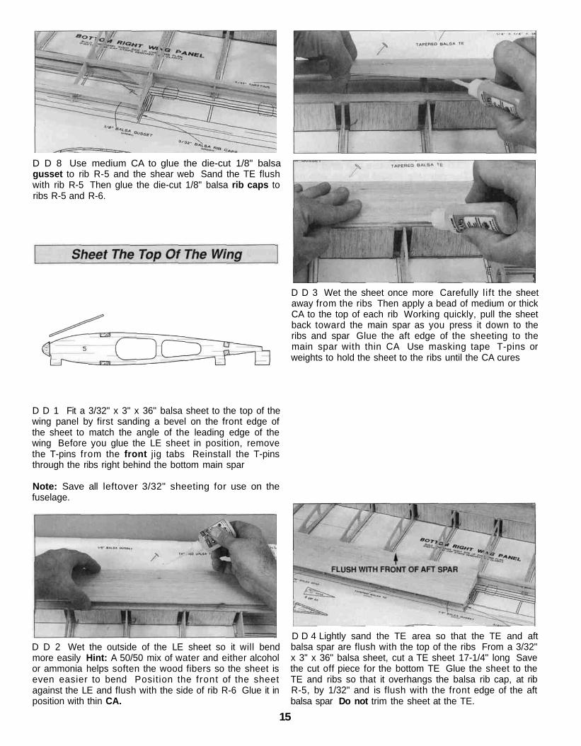
D D 8 Use medium CA to glue the die-cut 1/8" balsagusset to rib R-5 and the shear web Sand the TE flushwith rib R-5 Then glue the die-cut 1/8" balsa rib caps toribs R-5 and R-6.
D D 3 Wet the sheet once more Carefully l i f t the sheetaway from the ribs Then apply a bead of medium or thickCA to the top of each rib Working quickly, pull the sheetback toward the main spar as you press it down to theribs and spar Glue the aft edge of the sheeting to themain spar with thin CA Use masking tape T-pins orweights to hold the sheet to the ribs until the CA cures
D D 1 Fit a 3/32" x 3" x 36" balsa sheet to the top of thewing panel by first sanding a bevel on the front edge ofthe sheet to match the angle of the leading edge of thewing Before you glue the LE sheet in position, removethe T-pins from the front jig tabs Reinstall the T-pinsthrough the ribs right behind the bottom main spar
Note: Save all leftover 3/32" sheeting for use on thefuselage.
D D 2 Wet the outside of the LE sheet so it will bendmore easily Hint: A 50/50 mix of water and either alcoholor ammonia helps soften the wood fibers so the sheet iseven easier to bend Position the front of the sheetagainst the LE and flush with the side of rib R-6 Glue it inposition with thin CA.
D D 4 Lightly sand the TE area so that the TE and aftbalsa spar are flush with the top of the ribs From a 3/32"x 3" x 36" balsa sheet, cut a TE sheet 17-1/4" long Savethe cut off piece for the bottom TE Glue the sheet to theTE and ribs so that it overhangs the balsa rib cap, at ribR-5, by 1/32" and is flush with the front edge of the aftbalsa spar Do not trim the sheet at the TE.
15

D D 5. Glue a 3/32" x 3/8" x 30" balsa cap strip on thetop of rib R-6. The cap strip should be flush with theoutside of the rib and extend past the TE by 1/2". Use theleftover cap strip to cover the aft balsa spar from rib R-5to R-6. The cap strip should be flush with the front of theaft balsa spar.
D D 8. From the 3/32" x 3/8" x 30" balsa sticks, cut capstrips. Use medium CA to glue them to the tops of theribs. Be sure to cut an opening for the strut slot in the capstrip on rib R-PB.
D D 9. Remove the T-pins and take the wing off yourbuilding board. Carefully remove the jig tabs. Using asanding bar with 150-grit sandpaper, sand the ribs flushwith the bottom main spar and aft balsa spar. Sand the TEsheet aft of the TE to match the angle of the TE and ribs.
D D 6. To locate the slot for the strut tab in rib R-PB,place a mark 1/2" and 1-1/2" from the aft edge of the topmain spar. Use the side of rib R-PB as a guide to markthe sides of the slot. Using a sharp hobby knife, trim theLE sheet from over the slot.
D D 7. Use a 3/32" x 3" x 30" balsa sheet to make thecenter sheeting between the LE sheet and the TE sheet.Before you glue the center sheeting in position, removethe T-pins from ribs R-1B, R-2B and R-5.
D D 1. Use a razor saw and sanding bar to accurately cutthe spars, LE, TE and top sheet flush with rib R-1B.
D D 2. On rib R-1B use a straightedge to draw linesconnecting the front of the aft balsa spars, and the cornerof the notch in front of the aft balsa spar. Also, draw linesconnecting the front and aft corners of the top and bottommain spars. Then draw lines continuing the sides of thedie-cut rectangle. Use a razor saw to cut slotsin front of the aft balsa spar and in front and behind themain spar.
16

D D 3. Use 6-minute epoxy to glue the 1/4" x 3/8" x3-3/4" hardwood hatch blocks into the notches in ribs R-5B and R-PB. Af ter the epoxy has cured, cut hatchguides from 1/4" x 1/4" x 30" balsa stick. The guides fitbetween the hatch blocks and are flush with the top of ribR-5B and R-PB. Glue in place with thin CA.
D D 4. Fit a 3/32" x 3" x 36" balsa sheet to the bottom ofthe wing panel by first sanding a bevel on the front edgeof the sheet so it matches the leading edge of the wing.Install the bottom LE sheet following the same procedureused to install the top LE sheet.
D D 5. From the 3/32" x 3" x 36" balsa sheet leftoverfrom the top TE, sheet the bottom TE from rib R-1B to R-5following the same procedure.
D D 6. Glue a 3/32" x 3/8" x 30" balsa cap strip on thebottom of rib R-6. The cap strip should be flush with theoutside of the rib. Use the left over cap strip to sheet theaft balsa spar from rib R-5 to R-6. The cap strip should beflush with the front of the aft balsa spar.
D D 7. Use a 3/32" x 3" x 30" balsa sheet to sheet thecenter of the wing panel between the LE and TE sheets.There may be a slight gap between the sheets. Use thickCA to fill the gap, wipe off the excess then spray the areawith accelerator to harden the joint.
D D 9. Use medium CA to glue 3/32" balsa cap strips tothe ribs at the side of the aileron servo hatch. From a3/32" x 3" x 24" balsa sheet, fill the gap between the hatchand the LE sheet and the hatch and the TE sheet. Leavea 1/32" gap around the hatch to allow for the thickness ofthe covering. Save the leftover sheet for use around thehatch on the other wing panels.
D D 10. From the 3/32" x 3/8" x 30" balsa sticks, cut capstrips for the remaining ribs. Use medium CA to glue themto the bottom of the ribs.
D D 1. Use a razor saw and sanding bar with 150-gritsandpaper to trim the bottom sheeting flush with rib R-1B.Also, sand the sheeting in the aileron bay flush with theaft balsa spars and the balsa rib caps.
D D 8. Center the die-cut 1/16" birch ply aileron servohatch over the opening for the aileron servo. Tape thehatch in place and drill six 1/16" pilot holes at the punchmarks on the aileron hatch and into the hatch blocks.Remove the hatch and place a drop of thin CA in eachhole in the hatch block. Wipe off the excess CA. Enlargethe holes to 1/8". Reinstall the hatch. Secure the hatchto the hatch blocks with six #2 x 3/8" flat headscrews (SCRW024).
D D 2. From the 5/16" x 15/16" x 18" balsa stick make asub TE to fit between the rib caps, against the aft balsaspars. Glue the sub TE centered on the aft balsa sparsand rib caps. Use a sanding bar to sand the edges of thesub TE flush the the wing sheeting.
D D 3. Use medium CA to glue the die-cut 1/8" balsawing tip perpendicular to rib R-6. Glue the die-cut 1/8"balsa wing tip formers to the top and bottom of the wingtip. Sand the tip of the formers flush with rib R-6.
17

How To Make Servo Lead Tubes:
When the aileron servos are mounted out in the wing, itcan be difficult to run the servo wires through the ribs tothe wing root. An easy solution is to make servowire tubes.
D 2. After you are satisfied with the fit, take the wingjoiners and bolt plate out of the wing panels. Mixapproximately 1 oz. of 30-minute epoxy. Use plenty ofepoxy to coat the main and aft spars, the slot in ribsR-1B and R-2B, the wing joiners, bolt plate and the faceof ribs R-1B. Insert the wing joiners and bolt plate in thewing panel and press the wing panels together. Wipe offany excess epoxy with rubbing alcohol and a paper towel.Tape the two wing panels together and weight them downon a flat surface. Check that the LE is straight and thewing panels are flat against the surface.
A. Cut a piece of newspaper slightly longer than thelength needed to reach from the aileron servo bay to thewing root.
B. Roll the newspaper into a tube slightly smaller thanthe holes in the wing ribs. Use a couple of pieces of tapeto hold the tube together.
C. Insert the tube into the wing aligning the holes withthe tube. Tack glue the tube to the ribs with CA.
D 4. Give the wing panel a quick sanding. Then set itaside while you go back and build the left wing panel.
D 3. Use a sanding bar to sand the bottom center sectionsmooth and the TE straight. Draw a centerline on the topof the die-cut 1/8" plywood wing plate. Also, draw a line1/4" from the aft edge. Sand a taper on the edges of thewing plate. Use 6-minute epoxy to glue the wing plate,centered on the TE of the wing. Note: The wing plateoverhangs the TE by 1/4" as shown on the wing plan.After the epoxy cures, balsa filler can be applied to makea smooth transit ion from the wing plate tothe wing.
D 1. Sand the spars, LE, TE and sheeting flush with ribR-1B. Without using any glue, test join the wing panelsby inserting the 1/8" x 1-5/8" x 5" plywood forward wingjoiners, the 1/8" x 5/8" x 5" plywood aft wing joiner andthe 1/4" x 1" x 12" plywood wing bolt plate into the rightwing panel. Join the left wing panel to the right wingpanel. Set the wing on a flat surface and use a straight-edge to check that the LE is straight. If not, use a sandingbar to sand the wing root and test fit again.
D D 1. Lay a piece of wax paper over the right aileronplan. Cut a 3/32" x 3" x 36" balsa sheet in half. Trim bothsheets to 2-1/8" wide to make the top and bottomaileron sheeting. Pin one of the sheets in position overthe plan.
18
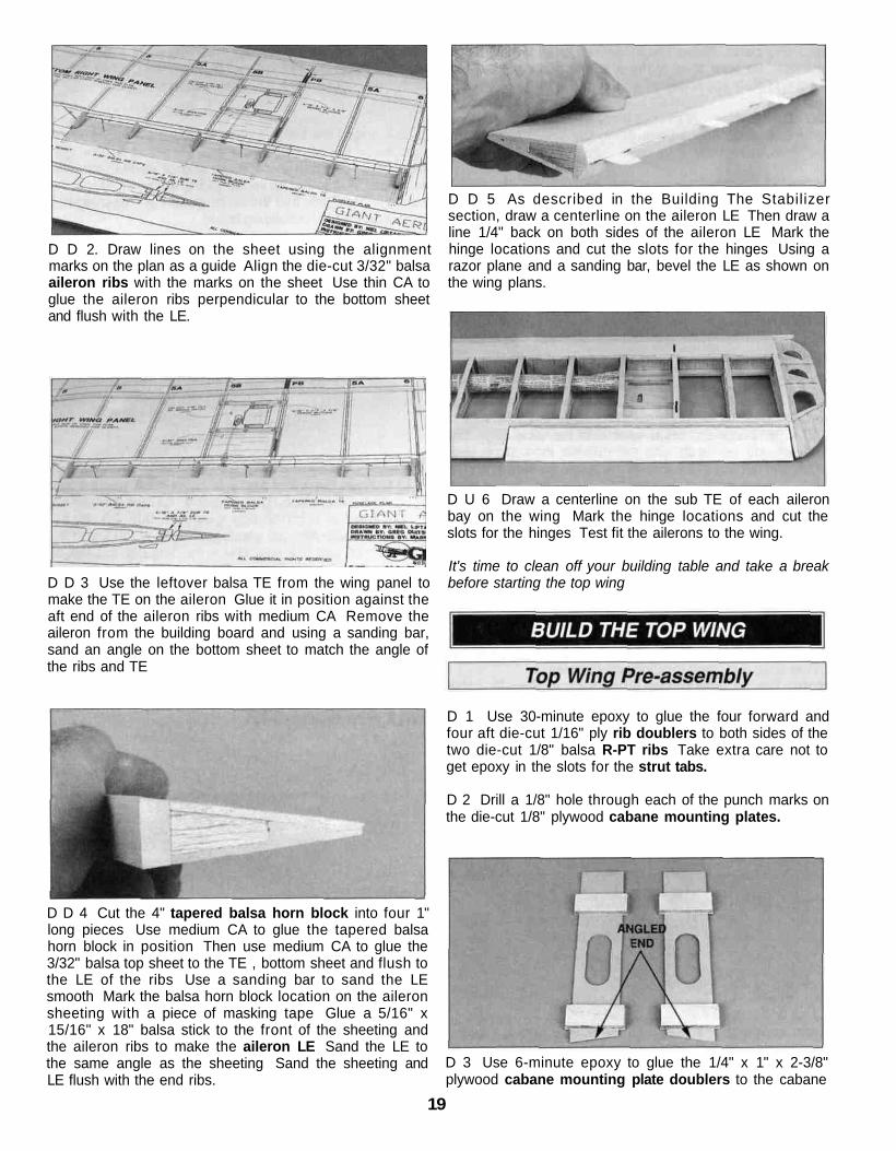
D D 2. Draw lines on the sheet using the alignmentmarks on the plan as a guide Align the die-cut 3/32" balsaaileron ribs with the marks on the sheet Use thin CA toglue the aileron ribs perpendicular to the bottom sheetand flush with the LE.
D D 3 Use the leftover balsa TE from the wing panel tomake the TE on the aileron Glue it in position against theaft end of the aileron ribs with medium CA Remove theaileron from the building board and using a sanding bar,sand an angle on the bottom sheet to match the angle ofthe ribs and TE
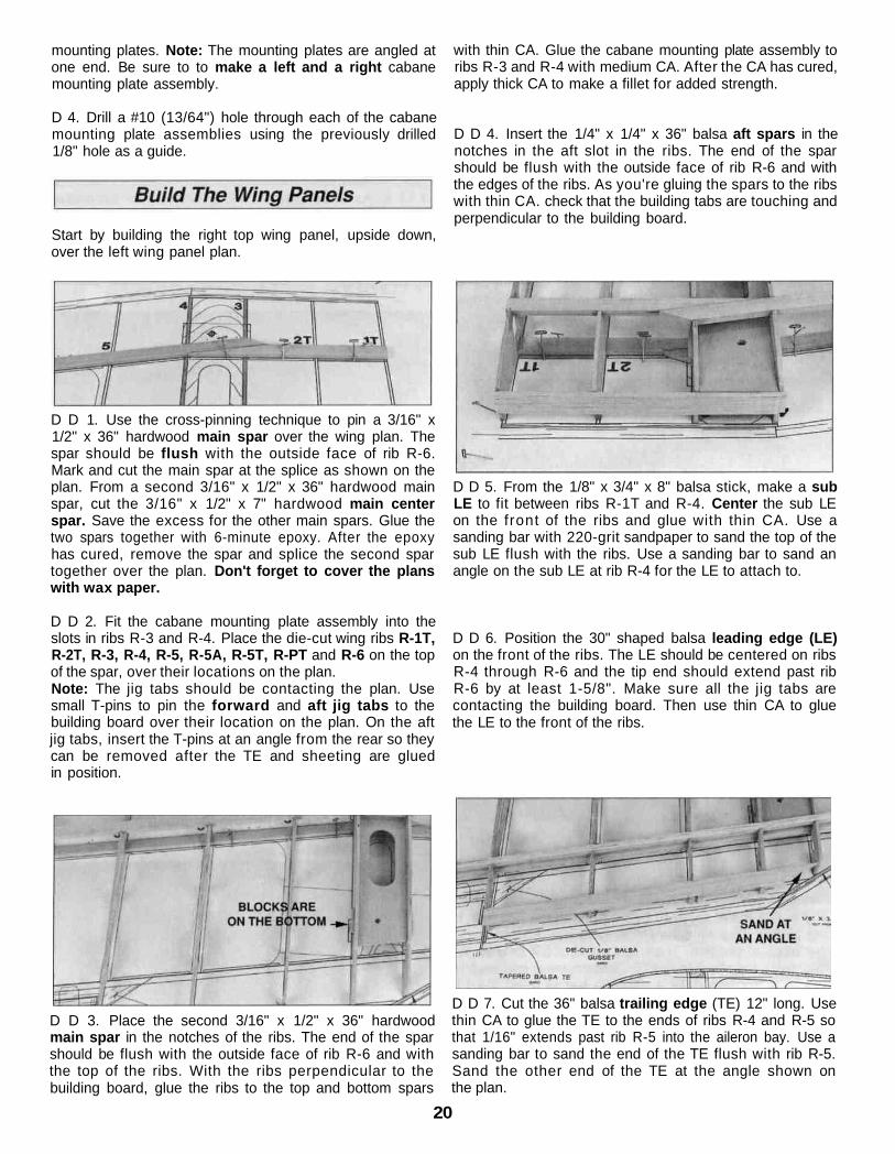
D D 5 As described in the Building The Stabilizersection, draw a centerline on the aileron LE Then draw aline 1/4" back on both sides of the aileron LE Mark thehinge locations and cut the slots for the hinges Using arazor plane and a sanding bar, bevel the LE as shown onthe wing plans.
D U 6 Draw a centerline on the sub TE of each aileronbay on the wing Mark the hinge locations and cut theslots for the hinges Test fit the ailerons to the wing.
It's time to clean off your building table and take a breakbefore starting the top wing
D D 4 Cut the 4" tapered balsa horn block into four 1"long pieces Use medium CA to glue the tapered balsahorn block in position Then use medium CA to glue the3/32" balsa top sheet to the TE , bottom sheet and flush tothe LE of the ribs Use a sanding bar to sand the LEsmooth Mark the balsa horn block location on the aileronsheeting with a piece of masking tape Glue a 5/16" x15/16" x 18" balsa stick to the front of the sheeting andthe aileron ribs to make the aileron LE Sand the LE tothe same angle as the sheeting Sand the sheeting andLE flush with the end ribs.
D 1 Use 30-minute epoxy to glue the four forward andfour aft die-cut 1/16" ply rib doublers to both sides of thetwo die-cut 1/8" balsa R-PT ribs Take extra care not toget epoxy in the slots for the strut tabs.
D 2 Drill a 1/8" hole through each of the punch marks onthe die-cut 1/8" plywood cabane mounting plates.
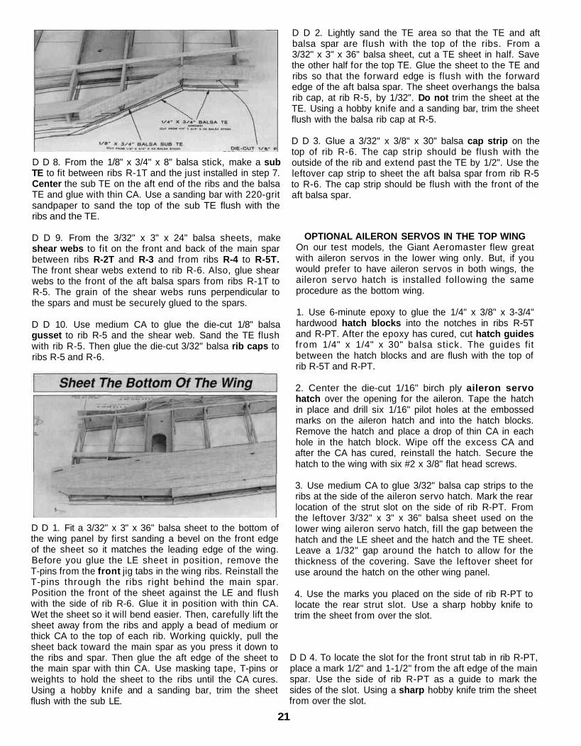
D 3 Use 6-minute epoxy to glue the 1/4" x 1" x 2-3/8"plywood cabane mounting plate doublers to the cabane
19
mounting plates. Note: The mounting plates are angled atone end. Be sure to to make a left and a right cabanemounting plate assembly.
D 4. Drill a #10 (13/64") hole through each of the cabanemounting plate assemblies using the previously drilled1/8" hole as a guide.
with thin CA. Glue the cabane mounting plate assembly toribs R-3 and R-4 with medium CA. After the CA has cured,apply thick CA to make a fillet for added strength.
D D 4. Insert the 1/4" x 1/4" x 36" balsa aft spars in thenotches in the aft slot in the ribs. The end of the sparshould be flush with the outside face of rib R-6 and withthe edges of the ribs. As you're gluing the spars to the ribswith thin CA. check that the building tabs are touching andperpendicular to the building board.
Start by building the right top wing panel, upside down,over the left wing panel plan.
D D 1. Use the cross-pinning technique to pin a 3/16" x1/2" x 36" hardwood main spar over the wing plan. Thespar should be flush with the outside face of rib R-6.Mark and cut the main spar at the splice as shown on theplan. From a second 3/16" x 1/2" x 36" hardwood mainspar, cut the 3/16" x 1/2" x 7" hardwood main centerspar. Save the excess for the other main spars. Glue thetwo spars together with 6-minute epoxy. After the epoxyhas cured, remove the spar and splice the second spartogether over the plan. Don't forget to cover the planswith wax paper.
D D 2. Fit the cabane mounting plate assembly into theslots in ribs R-3 and R-4. Place the die-cut wing ribs R-1T,R-2T, R-3, R-4, R-5, R-5A, R-5T, R-PT and R-6 on the topof the spar, over their locations on the plan.Note: The jig tabs should be contacting the plan. Usesmall T-pins to pin the forward and aft jig tabs to thebuilding board over their location on the plan. On the aftjig tabs, insert the T-pins at an angle from the rear so theycan be removed after the TE and sheeting are gluedin position.
D D 5. From the 1/8" x 3/4" x 8" balsa stick, make a subLE to fit between ribs R-1T and R-4. Center the sub LEon the front of the ribs and glue with thin CA. Use asanding bar with 220-grit sandpaper to sand the top of thesub LE flush with the ribs. Use a sanding bar to sand anangle on the sub LE at rib R-4 for the LE to attach to.
D D 6. Position the 30" shaped balsa leading edge (LE)on the front of the ribs. The LE should be centered on ribsR-4 through R-6 and the tip end should extend past ribR-6 by at least 1-5/8". Make sure all the jig tabs arecontacting the building board. Then use thin CA to gluethe LE to the front of the ribs.
D D 3. Place the second 3/16" x 1/2" x 36" hardwoodmain spar in the notches of the ribs. The end of the sparshould be flush with the outside face of rib R-6 and withthe top of the ribs. With the ribs perpendicular to thebuilding board, glue the ribs to the top and bottom spars
D D 7. Cut the 36" balsa trailing edge (TE) 12" long. Usethin CA to glue the TE to the ends of ribs R-4 and R-5 sothat 1/16" extends past rib R-5 into the aileron bay. Use asanding bar to sand the end of the TE flush with rib R-5.Sand the other end of the TE at the angle shown onthe plan.
20
D D 8. From the 1/8" x 3/4" x 8" balsa stick, make a subTE to fit between ribs R-1T and the just installed in step 7.Center the sub TE on the aft end of the ribs and the balsaTE and glue with thin CA. Use a sanding bar with 220-gritsandpaper to sand the top of the sub TE flush with theribs and the TE.
D D 9. From the 3/32" x 3" x 24" balsa sheets, makeshear webs to fit on the front and back of the main sparbetween ribs R-2T and R-3 and from ribs R-4 to R-5T.The front shear webs extend to rib R-6. Also, glue shearwebs to the front of the aft balsa spars from ribs R-1T toR-5. The grain of the shear webs runs perpendicular tothe spars and must be securely glued to the spars.
D D 10. Use medium CA to glue the die-cut 1/8" balsagusset to rib R-5 and the shear web. Sand the TE flushwith rib R-5. Then glue the die-cut 3/32" balsa rib caps toribs R-5 and R-6.
D D 1. Fit a 3/32" x 3" x 36" balsa sheet to the bottom ofthe wing panel by first sanding a bevel on the front edgeof the sheet so it matches the leading edge of the wing.Before you glue the LE sheet in position, remove theT-pins from the front jig tabs in the wing ribs. Reinstall theT-pins through the ribs right behind the main spar.Position the front of the sheet against the LE and flushwith the side of rib R-6. Glue it in position with thin CA.Wet the sheet so it will bend easier. Then, carefully lift thesheet away from the ribs and apply a bead of medium orthick CA to the top of each rib. Working quickly, pull thesheet back toward the main spar as you press it down tothe ribs and spar. Then glue the aft edge of the sheet tothe main spar with thin CA. Use masking tape, T-pins orweights to hold the sheet to the ribs until the CA cures.Using a hobby knife and a sanding bar, trim the sheetflush with the sub LE.
D D 2. Lightly sand the TE area so that the TE and aftbalsa spar are flush with the top of the ribs. From a3/32" x 3" x 36" balsa sheet, cut a TE sheet in half. Savethe other half for the top TE. Glue the sheet to the TE andribs so that the forward edge is flush with the forwardedge of the aft balsa spar. The sheet overhangs the balsarib cap, at rib R-5, by 1/32". Do not trim the sheet at theTE. Using a hobby knife and a sanding bar, trim the sheetflush with the balsa rib cap at R-5.
D D 3. Glue a 3/32" x 3/8" x 30" balsa cap strip on thetop of rib R-6. The cap strip should be flush with theoutside of the rib and extend past the TE by 1/2". Use theleftover cap strip to sheet the aft balsa spar from rib R-5to R-6. The cap strip should be flush with the front of theaft balsa spar.
OPTIONAL AILERON SERVOS IN THE TOP WINGOn our test models, the Giant Aeromaster flew greatwith aileron servos in the lower wing only. But, if youwould prefer to have aileron servos in both wings, theaileron servo hatch is installed following the sameprocedure as the bottom wing.
1. Use 6-minute epoxy to glue the 1/4" x 3/8" x 3-3/4"hardwood hatch blocks into the notches in ribs R-5Tand R-PT. After the epoxy has cured, cut hatch guidesf rom 1/4" x 1/4" x 30" balsa stick. The guides fitbetween the hatch blocks and are flush with the top ofrib R-5T and R-PT.
2. Center the die-cut 1/16" birch ply aileron servohatch over the opening for the aileron. Tape the hatchin place and drill six 1/16" pilot holes at the embossedmarks on the aileron hatch and into the hatch blocks.Remove the hatch and place a drop of thin CA in eachhole in the hatch block. Wipe off the excess CA andafter the CA has cured, reinstall the hatch. Secure thehatch to the wing with six #2 x 3/8" flat head screws.
3. Use medium CA to glue 3/32" balsa cap strips to theribs at the side of the aileron servo hatch. Mark the rearlocation of the strut slot on the side of rib R-PT. Fromthe leftover 3/32" x 3" x 36" balsa sheet used on thelower wing aileron servo hatch, fill the gap between thehatch and the LE sheet and the hatch and the TE sheet.Leave a 1/32" gap around the hatch to allow for thethickness of the covering. Save the leftover sheet foruse around the hatch on the other wing panel.
4. Use the marks you placed on the side of rib R-PT tolocate the rear strut slot. Use a sharp hobby knife totrim the sheet from over the slot.
D D 4. To locate the slot for the front strut tab in rib R-PT,place a mark 1/2" and 1-1/2" from the aft edge of the mainspar. Use the side of rib R-PT as a guide to mark thesides of the slot. Using a sharp hobby knife trim the sheetfrom over the slot.
21

D D 5. Use a 3/32" x 3" x 24" balsa sheet to make thecenter sheeting that fits between the LE sheet and theTE sheet. Position the sheeting so that it is perpendicularto the ribs. Before you glue the center sheeting inposition, remove the T-pins from ribs R-1T through R-5.Note: The grain direction of the center sheeting should beperpendicular to the ribs as shown.
D D 3. Use the holes in the cabane mounting plate as aguide to drill a #10 (13/64") hole through the bottomsheeting. To prevent the balsa sheeting from splitting,place a wood block behind the sheeting while drillingthough it.
D D 6. From the 3/32" x 3/8" x 30" balsa sticks cut capstrips, then use medium CA to glue them to the tops of theribs. Be sure to cut an opening for the strut slot in the capstrip on rib R-PT.
D D 7. Remove the T-pins. Take the wing off yourbuilding board. Carefully remove the jig tabs and use asanding bar with 150-grit sandpaper to sand the ribs flushwith the bottom main spar and aft balsa spar. Sand the TEsheet, aft of the TE and the sub TE, to match the angle ofthe ribs.
D D 4. Tap the holes with a 1/4-20 tap. Add a couple ofdrops of thin CA to the holes to harden the threads. Thenretap the holes after the CA has fully cured.
D D 1. Use a razor saw and sanding bar to accurately cutthe spars, LE, TE and top sheet flush with rib R-1T.
D D 5. Fit a 3/32" x 3" x 36" balsa sheet to the top of thewing panel by first sanding a bevel on the front edge ofthe sheet so it matches the leading edge of the wing.Also, sand the sub LE flush with the ribs. Install the top LEsheet following the same procedure used to install thebottom LE sheet.
D D 2. On rib R-1T use a straightedge to draw a line fromthe front edge of the top main spar to the front edge of thebottom main spar. Draw a line from the back edge of thetop main spar to the back edge of the bottom main spar.Draw lines continuing the sides of the die-cut rectangle.Use a razor saw to cut a slot in front and behind themain spar.
D D 6. From the remaining 3/32" x 3" x 36" balsa sheetused to sheet the bottom TE, sheet the top TE from ribR-1T to R-5 following the same procedure.
D D 7. Glue a 3/32" x 3/8" x 30" balsa cap strip on thetop of rib R-6. The cap strip should be flush with theoutside of the rib. Use the leftover cap strip to sheet theaft balsa spar from rib R-5 to R-6. The cap strip should beflush with the front of the aft balsa spar.
D D 8. Use a 3/32" x 3" x 24" balsa sheet to make thecenter sheeting between the LE and TE sheet on the topof the wing.
22

D D 9. From the 3/32" x 3/8" x 30" balsa sticks, cut capstrips, and then use medium CA to glue them to thebottom of the ribs.
D D 1. Use a razor saw and sanding bar with 150-gritsandpaper to trim the top sheeting flush with rib R-1T andthe sub LE and TE. Also sand the sheeting, in the aileronbay area, flush with the aft balsa spars and the balsarib caps.
D D 2. From the 5/16" x 15/16" x 18" balsa stick, cut asub TE to fit between the rib caps, against the aft balsaspars in the aileron bay. Glue the sub TE to the aft balsaspars and use a sanding bar to sand the edges flush withthe wing sheeting.
D 1. Sand the spars, LE, TE and sheeting flush with ribR-1T. Sand the wing tip ribs flush with the top and bottomsheeting. Using a razor saw, cut the 1/8" x 1-5/8" x 5"plywood forward wing joiners 4-13/16" long. Withoutusing any glue, test join the wing panels by inserting theforward wing joiners and the two die-cut 1/8" plywood aftwing joiners into the right wing panel. Join the left wingpanel to the right wing panel and set the wing on a flatsurface. Use a straightedge along the sub LE to check thatthe LE is straight.
D 2. After you are satisfied with the fit, take the wing joinersout of the wing panels. Mix approximately 1 oz. of 30-minute epoxy. Use plenty of epoxy to coat the main and aftspars, the wing joiners and the face of ribs R-1T. Insert thewing joiners in the wing panel and press the wing panelstogether. Wipe off any excess epoxy with rubbing alcoholand a paper towel. Tape the two wing panels together andweight them down on a flat surface. Check that the sub LEis straight and the wing panels are flat against the surface.
D D 3. Use medium CA to glue the die-cut 1/8" balsawing tip (TTW) perpendicular to rib R-6. Glue the die-cut1/8" balsa wing tip formers to the top and bottom of thewing tip. Sand the tip of the formers flush with rib R-6.
D 4. Give the entire wing panel a rough sanding and set itaside while you go back and build the left wing panel.
D 3. Use a sanding bar and 220-grit sandpaper to sand thesub LE flat. Cut the 30" balsa LE to fit on the sub LEbetween the previously installed LE'S. When satisfied withthe fit glue the LE to the sub LE with medium CA.
D 4. From the 5/16" x 15/16" x 18" balsa stick make thecenter trailing edge. Use medium CA to glue the TEcentered on the sub TE. With a razor plane and a sandingbar, sand the TE flush with the top and bottom sheeting.Then sand a radius on the three TE pieces youjust installed.
23

D D 1. Position a piece of wax paper over the right aileronplan. Trim a 3/32" x 3" x 36" balsa sheet 2-1/8" wide. Fromthe narrowed balsa sheet, make a top and bottom aileronsheet. Cut the sheet 1/16" longer than the plan. Pin one ofthe sheets in position over the plan.
D D 2. Use thin CA to glue the eight die-cut 3/32" balsaaileron ribs perpendicular to the bottom sheet and flushwith the LE. Use the marks on the plan to align the ribs.
D D 5. As described in the Building The Stabilizer section,draw a centerline on the aileron LE. Then draw a line 1/4"back on both sides of the aileron LE. Mark the hingelocations and cut the slots for the hinges. Using a razorplane and a sanding bar, bevel the LE as shown on thewing cross-section.
D D 6. Draw a centerline on the sub TE of each aileronbay on the wing. Mark the hinge locations on the wing andthe aileron and cut the slots for the hinges. Test fit theailerons to the wing.
D 7. Go back to step 1 and build the second aileron.
D D 3. Use the leftover balsa TE from the wing panel tomake the TE on the aileron. Glue it in position against theaft end of the aileron ribs with medium CA. Remove theaileron from the building board and using a sanding bar,sand an angle on the bottom sheet to match the angle ofthe ribs and TE.
D D 4. If you are installing optional aileron servos in thetop wing, use medium CA to glue the tapered balsa hornblock in position. For both versions use medium CA to gluethe 3/32" balsa top sheet to the TE, bottom sheet and flushto the LE of the ribs. Use a sanding bar to sand the LEsmooth. Use a piece of masking tape to mark the balsahorn block, if installed. Use the leftover 5/16" x 1" x 36"balsa stick from the wing panel to make the aileron LE.Sand the LE to the same angle as the sheeting and flushwith the end ribs.
24
D 1. Use 6-minute epoxy to glue the shaped 1/4" x 1-1/2" x4-1/2" ply cabane doublers to the top of the die-cut 1/8" plytop deck (TD) centered between the tabs and the die-cutholes. Note: The bottom side of the top deck features anembossed (TD).
D 2. Drill a 5/32" hole at each punch mark through the topdeck and cabane doublers.
D 4. Draw centerlines connecting the punch marks on thefront of the die-cut 1/8" ply firewall (A). Use 30-minuteepoxy to glue firewall (A) to the shaped 1/4" ply firewalldoubler. Make sure the lines you previously drew arefacing forward and the bottom and edges of firewall (A)and the firewall doubler are aligned. Wipe off the excessepoxy before it cures.
Note: If firewall (A) and the firewall doubler are warped,simply clamping them together may not "cancel out" thewarp. It is best to clamp the assembly to a table or aflat board.
Important: We strongly recommend that any engine usedon the Giant Aeromaster be installed on an isolated shockabsorbing engine mount. The use of this type engine mountwill help prevent damage to the radio system and theairplane frame due to engine vibration.
D 5. Skip ahead to step 10 if you will be installing therecommended U.S. Engines 41cc engine and J'TECisolated engine mount on your Giant Aeromaster. If you arenot installing the isolated engine mount, use 30-minuteepoxy to laminate the three 1/4" x 3-1/4" x 3-3/4" plyengine spacers together. If you will be installing a differentengine, center the engine on the firewall. The distance fromthe firewall to the front of the drive washer needs to be7-1/8" for the cowl to fit properly. Note: The followinginstructions are based on the installation of the U.S.Engines 41cc engine. Installation of your specific enginemay differ slightly.
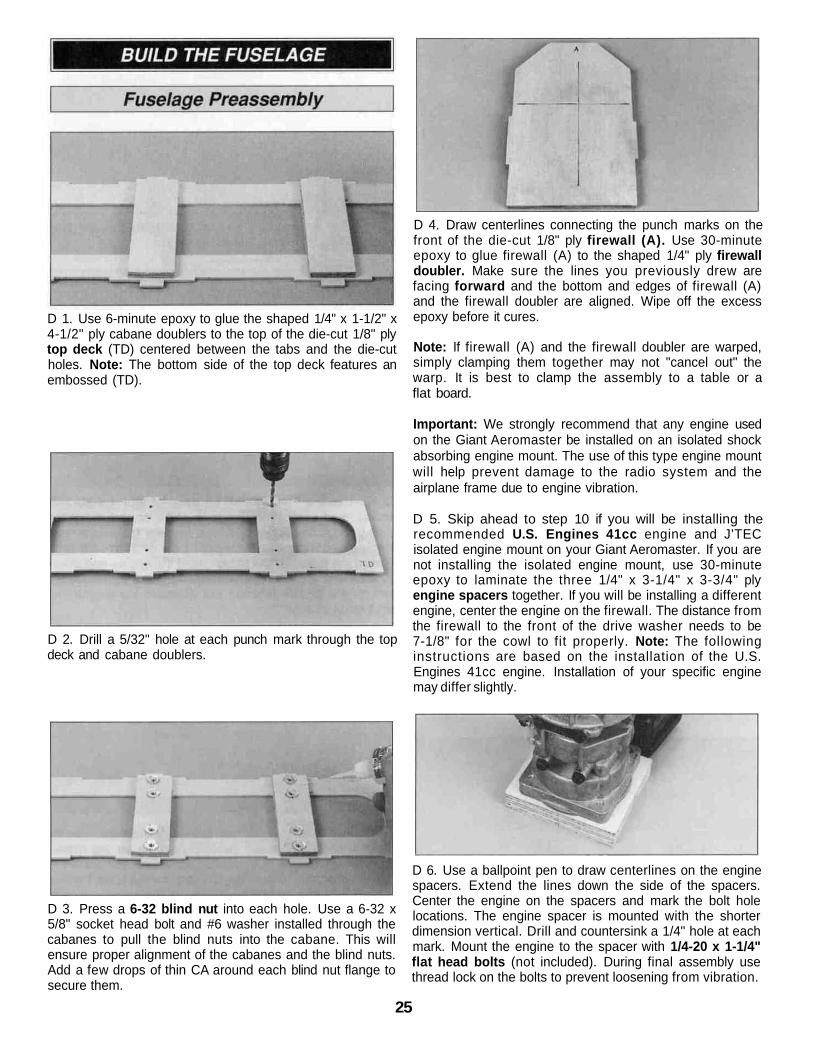
D 3. Press a 6-32 blind nut into each hole. Use a 6-32 x5/8" socket head bolt and #6 washer installed through thecabanes to pull the blind nuts into the cabane. This willensure proper alignment of the cabanes and the blind nuts.Add a few drops of thin CA around each blind nut flange tosecure them.
D 6. Use a ballpoint pen to draw centerlines on the enginespacers. Extend the lines down the side of the spacers.Center the engine on the spacers and mark the bolt holelocations. The engine spacer is mounted with the shorterdimension vertical. Drill and countersink a 1/4" hole at eachmark. Mount the engine to the spacer with 1/4-20 x 1-1/4"flat head bolts (not included). During final assembly usethread lock on the bolts to prevent loosening from vibration.
25

D 7. With the engine mounted on the engine spacer, tracearound the engine backplate. Mark the top of the enginespacer (the edge opposite the engine head). Remove theengine from the engine spacer. Clamp the engine spacer tothe firewall with the centerlines on the engine spaceraligned with the centerlines on the firewall. Make sure thetop of the engine spacer is to the top of the firewall (theangled end). Use a 3/16" drill bit to drill a hole in eachcorner of the engine spacer, outside the engine outline,through the engine spacer and firewall. Remove the enginespacer and enlarge the holes in only the firewall with a 1/4"drill bit.
D 8. Install 10-32 blind nuts (not included) in the back ofthe firewall. Gently tap the blind nuts in with a hammer.Apply a few drops of thin CA around each blind nut flangeto secure it.
D 12. Use a sharp hobby knife to carefully trim the stepfrom the four remaining rubber bushings.
D 9. Mount the engine to the engine spacer. Then mountthe engine spacer to the firewall with four 10-32 x 1-1/4"socket head bolts and #10 washers (not included). Place amark on the firewall in line with the throttle arm. If notinstalling an isolated engine mount, proceed to "AssembleThe Fuselage Sides."
D 13. Place a 1/4" washer on each of four 1/4-20 x 2"socket head bolts. From the back of the firewall insert thebolts through the rubber bushings. Install a 1/4" washer andstepless bushing (from step 12,) on each 1/4-20 bolt.Thread the bolts into the backplate of the engine and checkfor fit. Place a mark on the firewall in line with the throttlearm for the throttle pushrod exit. Remove the engine andset it aside for now.
D 10. To install the J'TEC isolated engine mount, removethe muffler and center the engine on the firewall using thelines on the firewall as a guide. Mark the bolt hole locationsand drill a 1/2" hole at each mark.
D 11. Insert a rubber step bushing in the front and rear ofeach hole. Note: The rubber bushings with attached blindnuts are not used in this engine installation.
D 1. On the die-cut 1/8" ply fuselage side doubler #3there are two embossed optional cut-outs for the rudderand elevator servos. If you prefer to mount your servos inthe tail, punch out one of the cut-outs, for the rudder servo,in one piece only and both cut-outs, for the elevator, in bothpieces. Use the punched out pieces glued to the back ofthe doubler as doublers for the servo screws. If you preferto mount the servos in the standard location inside thefuselage, punch out the narrow slots only. Glue the servocut-outs in place with thin CA. The slot in the fourth cut-outmay be used as an optional antenna exit.
26
D 2. Cover the fuselage side plan with wax paper. Pin thedie-cut 1/8" ply fuselage side doublers #1 through #7 inposition over the fuselage side plan and use thin CA to gluethe doublers together. Use medium CA to fill in any gaps inthe joints. Build two fuselage side doublers.
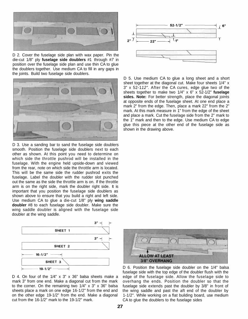
D 5. Use medium CA to glue a long sheet and a shortsheet together at the diagonal cut. Make four sheets 1/4" x3" x 52-112". After the CA cures, edge glue two of thesheets together to make two 1/4" x 6" x 52-1/2" fuselagesides. Note: For better strength, place the diagonal jointsat opposite ends of the fuselage sheet. At one end place amark 2" from the edge. Then, place a mark 22" from the 2"mark. At this mark measure in 1" from the edge of the sheetand place a mark. Cut the fuselage side from the 2" mark tothe 1" mark and then to the edge. Use medium CA to edgeglue this piece at the other end of the fuselage side asshown in the drawing above.
D 3. Use a sanding bar to sand the fuselage side doublerssmooth. Position the fuselage side doublers next to eachother as shown. At this point you need to determine onwhich side the throttle pushrod will be installed in thefuselage. With the engine held upside-down and viewedfrom the rear, note on which side the throttle arm is located.This will be the same side the rudder pushrod exits thefuselage. Label the doubler with the rudder slot punchedout the same as the side the throttle arm is on. If the throttlearm is on the right side, mark the doubler right side. It isimportant that you position the fuselage side doublers asshown above to ensure that you build a right and left side.Use medium CA to glue a die-cut 1/8" ply wing saddledoubler #8 to each fuselage side doubler. Make sure thewing saddle doubler is aligned with the fuselage sidedoubler at the wing saddle.
D 4. On four of the 1/4" x 3" x 36" balsa sheets make amark 3" from one end. Make a diagonal cut from the markto the corner. On the remaining two 1/4" x 3" x 36" balsasheets place a mark on one edge 16-1/2" from the end andon the other edge 19-1/2" from the end. Make a diagonalcut from the 16-1/2" mark to the 19-1/2" mark.
D 6. Position the fuselage side doubler on the 1/4" balsafuselage side with the top edge of the doubler flush with theedge of the fuselage side. Allow the fuselage side tooverhang the ends. Position the doubler so that thefuselage side extends past the doubler by 3/8" in front ofthe wing saddle and past the aft end of the doubler by1-1/2". While working on a flat building board, use mediumCA to glue the doublers to the fuselage sides
27

D 7 Draw a line 3/8" from the edge of the fuselage sidedoubler in front of the wing saddle Using a hobby knife (orrazor plane and sanding bar), trim the fuselage sides to thisline Trim and sand the remainder of the fuselage side flushwith the outer edge of the fuselage doubler Cut-out thenotches for the cabanes Cut the slots for the pushrod exitsat the aft end of the fuselage and use a round file to bevelthe ply doubler at the front of the notch.
D 10 Without using any glue, insert the die cut 1/8" plyformers (F), (G), (H) and (J) in their locations with thelarge round hole in the former on the bottom Formers (H)and (J) are installed with the embossed letters facingforward Formers (F) and (G) are installed so that the smallsingle hole that is off center is on the opposite side Fromthe rudder pushrod exit hole in the fuselage side Userubber bands placed around the fuselage sides to hold theformers in place
D 11 Use medium CA to glue the die-cut 1/8" ply bottomrear plate doubler (BD) to the aft end of the die-cut 1/8"ply bottom rear plate (BR) Refer to die GARF05 on page6 and the bottom of the fuselage tail section on thefuselage plan
D 8 Use thin CA to glue the die-cut 1/8" ply formers (B),(C), (D) and (E) into position perpendicular to the rightfuselage side The large tabs on formers (B), (C) and (D)face the top of the fuselage A notch will need to be cut inthe 1/4" balsa fuselage side in front of the wing saddle, toallow former (C) to fit flush with the front of the wing saddle
D 9. Position the right fuselage side over the top fuselageplan Attach the left fuselage side to the formers and alignboth fuselage sides with the plan Wood clamps work greatfor holding the fuselage together while checking thealignment When aligned, use thin CA to glue the formersperpendicular to the left fuselage sides
D 12 Install the die-cut 1/8" ply top rear plate (TR), thebottom rear plate (BR) and then the stab plate (SP)between the fuselage sides Note: The tabs on the top rearplate may require trimming for a perfect fit in the fuselagedoublers Use masking tape to hold the fuselage sides tothe top, bottom and stab plates
D 13. With the aft end of the fuselage flat against yourbuilding board, use thin CA to begin tack gluing thefollowing pieces checking alignment as you go Glue thetop rear plate to the fuselage sides Then glue formers (E),(F), (G), (H) and (J) to the fuselage sides, top rear plateand bottom rear plate Glue the bottom rear plate to thesides Do not glue the stab plate at this time
D 14 Remove the stab plate / hope you didn't glue it in'Use a round file or a hobby knife to bevel the pushrod exitholes to allow the guide tubes to slide through Carefullysand the outside of the 36" outer pushrod guide tubeswith coarse sandpaper so the glue will adhere better.
D 15. Install two of the guide tubes in the forward pushrodexit holes The guide tubes pass through the outer holes informer (H) through the middle holes in former (G) andcross each other before passing through the middle holesof former (F) (see photo at step 16) Approximately 1" of theguide tubes should protrude past the exit holes in thefuselage sides Insert a 4-40 x 36" pushrod into each tubeCheck that they slide smoothly through the tube withoutany restrictions.
28

D 21. After the epoxy cures, go back and apply mediumCA to reinforce the joints between the formers, top rearplate, bottom rear plate and fuselage sides. After the CAcures remove the masking tape.
D 16. Insert the third outer pushrod guide tube in therudder exit hole, through the middle hole in former (H) andthe off center hole in formers (G) and (F). Approximately 1"of guide tube should protrude past the exit hole. Use a 4-40pushrod to check for any restriction. An optional fourthguide tube (not included), used for routing the antennathrough the fuselage, can be inserted in the extra pushrodexit hole and through the hole in former (J) then through thelarge holes in the other formers.
D 17. Glue the pushrod guide tubes to the formers withmedium CA. Then glue the pushrod guide tubes to the exitslots with a 50/50 mixture of microballoons and epoxy.Completely fill the slot with the microballoons and epoxy soit can be sanded flush later. Note: Talcum powder may besubstituted for microballoons.
D 18. After the epoxy has cured use your bar sander and150-grit sandpaper to sand the pushrod guide tubes andepoxy filler flush with the fuselage sides.
D 22. Insert the right side of the firewall into the slot in thefront of the right fuselage side. Spread the front of thefuselage apart slightly and insert the left side of firewall intothe slot in the left fuselage side. Test fit the die-cut 1/8" plytank floor and the top deck between the fuselage sides.Note that the front of the tank floor and the top deck areangled. This angle sets the firewall at the proper rightthrust. Depending on the engine mounting method you mayneed to cut notches in the top deck and the tank floor toclear the blind nuts or rubber bushings. Cut two gussetsfrom the 1/4" x 1/4" x 16" hardwood stick to fit in the jointbetween the fuselage sides and the back of the firewall.After checking the fit of the parts, glue the firewall to thefuselage and the gussets to the firewall and fuselage sideswith 30-minute epoxy. Use masking tape or clamps to holdthe firewall until the epoxy cures.
D 19. Use 6-minute epoxy to glue the 1/4" x 3/4" x 1" birchply stab mounting blocks, between the embossed punchmarks, on the stab plate.
D 20. Use 30-minute epoxy to glue the stab plate to thefuselage, with the stab mounting blocks facing the inside ofthe fuselage.
D 23. Use 30-minute epoxy to glue the 3/8" x 4-3/8" x4-3/4" ply landing gear plate between the fuselage sidesand to formers (B) and (C). Use masking tape or clampsbetween the fuselage sides. Fit and glue the landing gearplate gussets made from 1/4" x 1/4" x 16" hardwoodaround the joint between the landing gear plate and thefuselage sides and formers on the inside of the fuselage.
29

D 24. Draw a line on the landing gear plate 1-1/2" from theaft edge of former (C). Then draw a centerline from front torear. Position the aluminum landing gear so that thesquare edge is aligned with the centerline and the 1-1/2"line is centered in the middle hole. Mark each hole locationand drill a 5/32" hole through the landing gear plate ateach mark.
D 25. Install six 6-32 blind nuts from inside the fuselage.Use 6-32 x 5/8" socket head bolts and #6 flat washersinserted through the landing gear and threaded into theblind nuts. Tighten the bolts to seat the blind nuts in theholes. Add a few drops of thin CA around each blind nut tosecure it.
D 27. Place the tank floor in position. From the 1/4" x 1/4" x16" hardwood stick, cut a gusset to fit in the joint betweenthe tank floor and the firewall. Use 6-minute epoxy to gluethe tank floor and the gusset in the fuselage.
D 28. Fit the top deck in position. From the 1/4" x 1/4" x 16"hardwood stick, cut gussets to fit in the joints, on the top andbottom, between the top deck and the firewall. Use 30-minuteepoxy to glue the top deck and gussets in position.
D 29. Drill a 3/16" hole through the firewall and former (B)at the mark for the throttle pushrod exit. Use 150-gritsandpaper to roughen up the 36" outer tubing. Insert theouter tubing through the firewall and slide it up to former(E). Trim the tubing flush with the firewall. Drill two 5/16"fuel line exit holes through the firewall aligned with the fuelinlet on the carburetor.
D 26. Use medium CA to glue the 3/8" x 2-9/16" x 4" balsablocks to the bottom front of the fuselage between thefirewall and the landing gear plate. From a 1/4" x 1/4" x 16"hardwood stick, epoxy two gussets inside the fuselage atthe joint between the bottom front blocks and former (B)and between the bottom front blocks and the firewall. Afterthe epoxy cures sand the front of the blocks flush with thefuselage sides.
D 1. Use thin CA to glue the die-cut 1/8" plywood formers(N), (P) and (Q) in position perpendicular to the toprear plate.
30
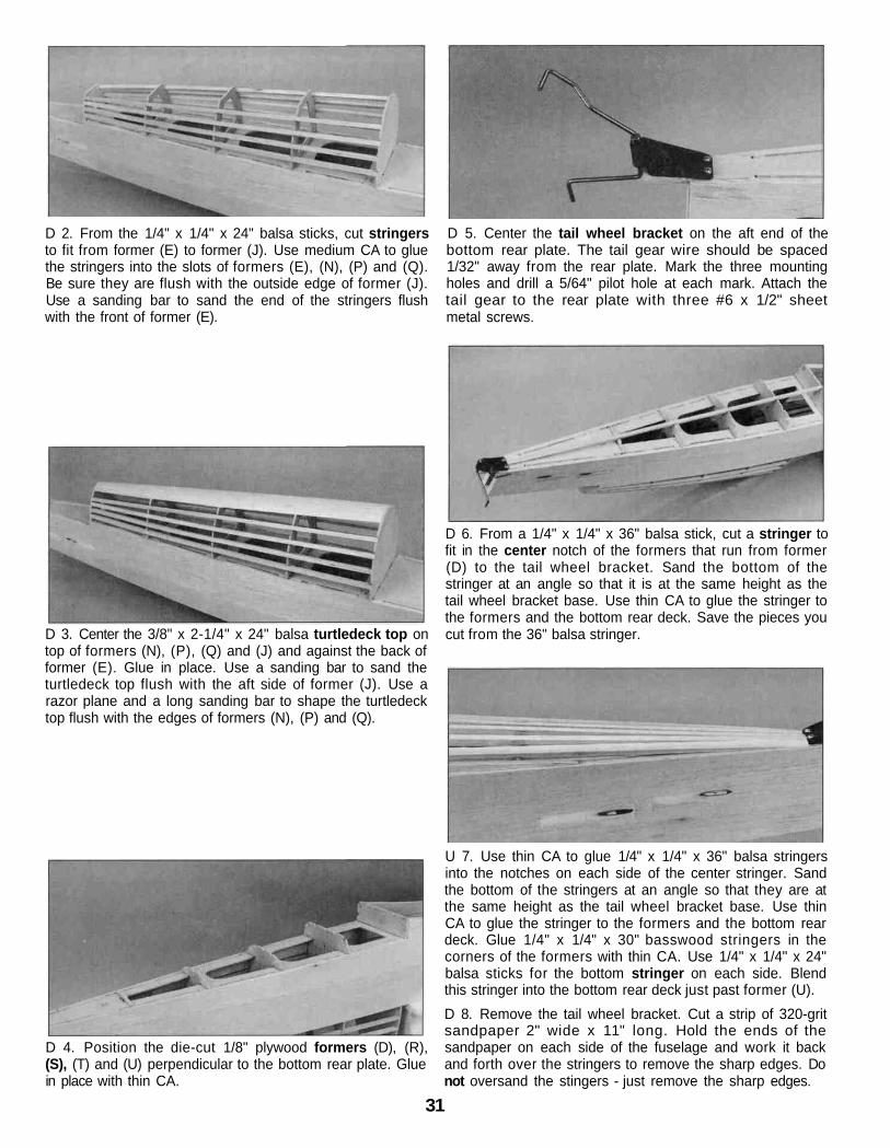
D 2. From the 1/4" x 1/4" x 24" balsa sticks, cut stringersto fit from former (E) to former (J). Use medium CA to gluethe stringers into the slots of formers (E), (N), (P) and (Q).Be sure they are flush with the outside edge of former (J).Use a sanding bar to sand the end of the stringers flushwith the front of former (E).
D 5. Center the tail wheel bracket on the aft end of thebottom rear plate. The tail gear wire should be spaced1/32" away from the rear plate. Mark the three mountingholes and drill a 5/64" pilot hole at each mark. Attach thetail gear to the rear plate with three #6 x 1/2" sheetmetal screws.
D 3. Center the 3/8" x 2-1/4" x 24" balsa turtledeck top ontop of formers (N), (P), (Q) and (J) and against the back offormer (E). Glue in place. Use a sanding bar to sand theturtledeck top flush with the aft side of former (J). Use arazor plane and a long sanding bar to shape the turtledecktop flush with the edges of formers (N), (P) and (Q).
D 6. From a 1/4" x 1/4" x 36" balsa stick, cut a stringer tofit in the center notch of the formers that run from former(D) to the tail wheel bracket. Sand the bottom of thestringer at an angle so that it is at the same height as thetail wheel bracket base. Use thin CA to glue the stringer tothe formers and the bottom rear deck. Save the pieces youcut from the 36" balsa stringer.
D 4. Position the die-cut 1/8" plywood formers (D), (R),(S), (T) and (U) perpendicular to the bottom rear plate. Gluein place with thin CA.
U 7. Use thin CA to glue 1/4" x 1/4" x 36" balsa stringersinto the notches on each side of the center stringer. Sandthe bottom of the stringers at an angle so that they are atthe same height as the tail wheel bracket base. Use thinCA to glue the stringer to the formers and the bottom reardeck. Glue 1/4" x 1/4" x 30" basswood stringers in thecorners of the formers with thin CA. Use 1/4" x 1/4" x 24"balsa sticks for the bottom stringer on each side. Blendthis stringer into the bottom rear deck just past former (U).D 8. Remove the tail wheel bracket. Cut a strip of 320-gritsandpaper 2" wide x 11" long. Hold the ends of thesandpaper on each side of the fuselage and work it backand forth over the stringers to remove the sharp edges. Donot oversand the stingers - just remove the sharp edges.
31
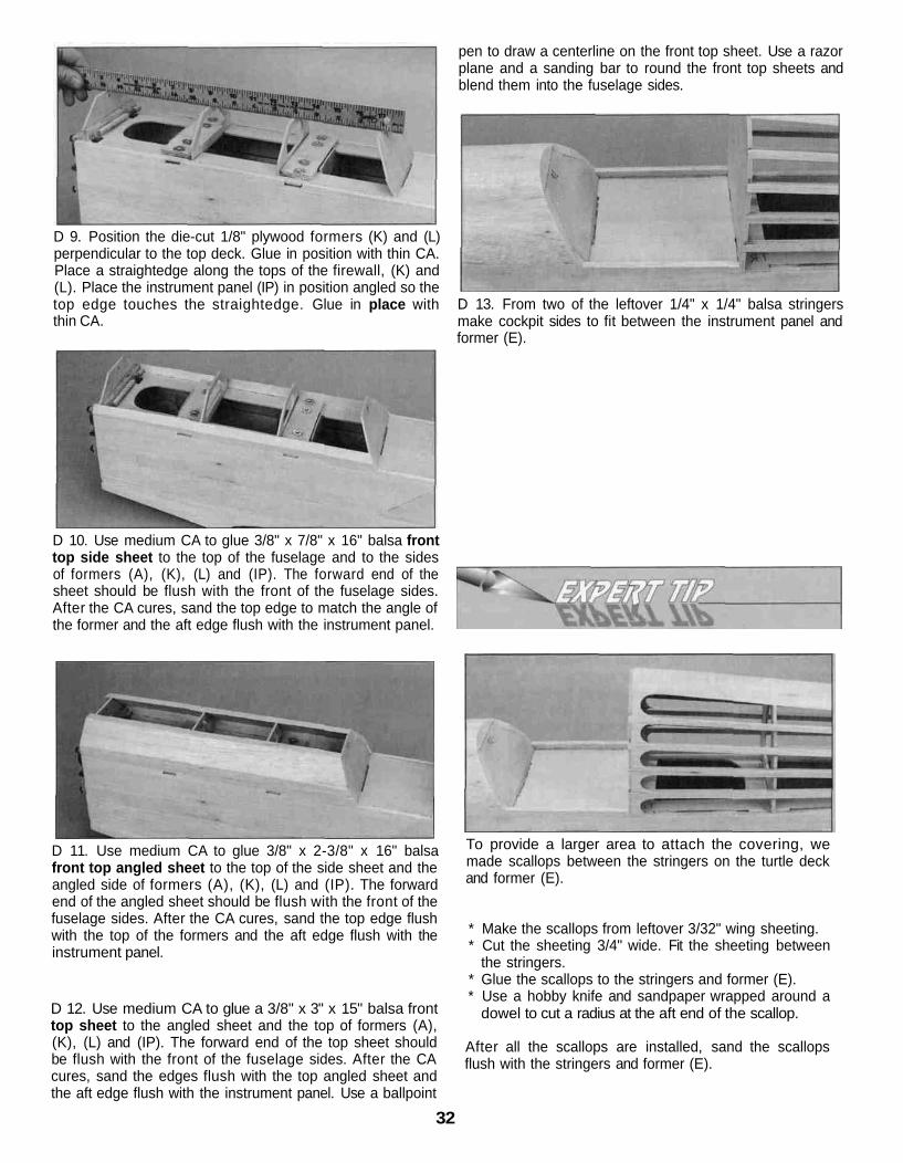
D 9. Position the die-cut 1/8" plywood formers (K) and (L)perpendicular to the top deck. Glue in position with thin CA.Place a straightedge along the tops of the firewall, (K) and(L). Place the instrument panel (IP) in position angled so thetop edge touches the straightedge. Glue in place withthin CA.
pen to draw a centerline on the front top sheet. Use a razorplane and a sanding bar to round the front top sheets andblend them into the fuselage sides.
D 13. From two of the leftover 1/4" x 1/4" balsa stringersmake cockpit sides to fit between the instrument panel andformer (E).
D 10. Use medium CA to glue 3/8" x 7/8" x 16" balsa fronttop side sheet to the top of the fuselage and to the sidesof formers (A), (K), (L) and (IP). The forward end of thesheet should be flush with the front of the fuselage sides.After the CA cures, sand the top edge to match the angle ofthe former and the aft edge flush with the instrument panel.
D 11. Use medium CA to glue 3/8" x 2-3/8" x 16" balsafront top angled sheet to the top of the side sheet and theangled side of formers (A), (K), (L) and (IP). The forwardend of the angled sheet should be flush with the front of thefuselage sides. After the CA cures, sand the top edge flushwith the top of the formers and the aft edge flush with theinstrument panel.
D 12. Use medium CA to glue a 3/8" x 3" x 15" balsa fronttop sheet to the angled sheet and the top of formers (A),(K), (L) and (IP). The forward end of the top sheet shouldbe flush with the front of the fuselage sides. After the CAcures, sand the edges flush with the top angled sheet andthe aft edge flush with the instrument panel. Use a ballpoint
To provide a larger area to attach the covering, wemade scallops between the stringers on the turtle deckand former (E).
* Make the scallops from leftover 3/32" wing sheeting.* Cut the sheeting 3/4" wide. Fit the sheeting between
the stringers.* Glue the scallops to the stringers and former (E).* Use a hobby knife and sandpaper wrapped around a
dowel to cut a radius at the aft end of the scallop.
After all the scallops are installed, sand the scallopsflush with the stringers and former (E).
32

D 1. Use 30-minute epoxy to glue the 1/4" x 1-3/8" x 4-1/2"ply forward and aft wing mounting plates in the notches ofthe wing saddle doubler
D 2 On the bottom of the lower wing, draw a line 1" backfrom the LE On this line, place marks 1-3/4" on each sideof the center of the wing At the marks, cut a 5/8" holethrough the sheeting only.
D 3. Seat the wing in the wing saddle and visually center iton the fuselage Pin a string to the center of bottom reardeck at the aft end Then extend it out to a wing tip Put apiece of tape on the string to mark the intersection of thestring and the wing tip Swing the string over to the other tipand see if the distance is the same (see diagram) Makeslight adjustments to the angle of the wing until the distancefrom the tail to the wing tips is equal.
D 4 Tape the wing in position At both marks on the wingplate use a 13/64" (or a #7 drill bit) to drill a hole throughthe wing and wing mounting plate, perpendicular to thewing plate At the front of the wing use a 13/64" (or a #7drill bit) to drill a hole through the wing bolt plate and wingmounting plate perpendicular to the wing bolt plateRemove the wing and enlarge the holes in the wing with a1/4" drill bit Cut threads in each wing mounting plate with a1/4-20 tap Put a couple of drops of thin CA on the threadsAfter it has fully cured, run the tap back through the holesto clean up the threads Bolt the wing to the fuselage withfour nylon 1/4-20 wing bolts and leave it in place for thenext few steps
D 1. Draw an accurate centerline on the top of the stab,perpendicular to the stab TE.
D 2 Center the stab on the stab plate using the centerlineyou drew in step #1 Study the aft end of the structure from8-10 feet back If the stab tips are not equidistant abovethe wing, carefully sand the high side of the stab plate untilthe stab is aligned Using the pin and string technique"accurately align the stab with the fuselage Once the stab isaccurately aligned, pin the stab to the stab plate
D 3 Carefully use a ballpoint pen to lightly mark whereboth of the fuselage sides contact the bottom of the stab.
D 4 Remove the stab from the stab plate but leave theT-pins in the stab Apply a film of 30-minute epoxy to the stabplate and the stab between the lines you made in step 3
D 5 Reposition the stab on the stab plate and insert theT-pins into the same holes Use the pin and string toconfirm the stab alignment then use weights, more T-pinsor clamps to hold the stab in position Wipe away excessepoxy before it cures, then recheck alignment Do notdisturb the model until the epoxy cures.
33
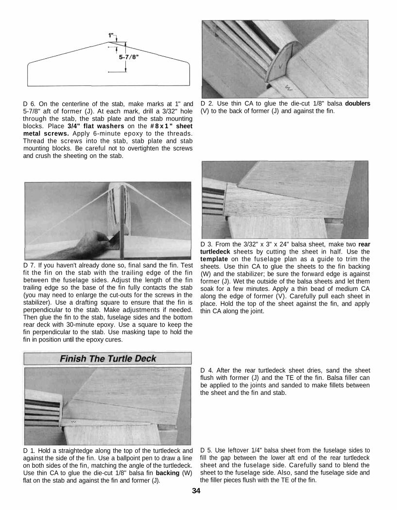
D 6. On the centerline of the stab, make marks at 1" and5-7/8" aft of former (J). At each mark, drill a 3/32" holethrough the stab, the stab plate and the stab mountingblocks. Place 3/4" flat washers on the # 8 x 1 " sheetmetal screws. Apply 6-minute epoxy to the threads.Thread the screws into the stab, stab plate and stabmounting blocks. Be careful not to overtighten the screwsand crush the sheeting on the stab.
D 7. If you haven't already done so, final sand the fin. Testfit the fin on the stab with the trailing edge of the finbetween the fuselage sides. Adjust the length of the fintrailing edge so the base of the fin fully contacts the stab(you may need to enlarge the cut-outs for the screws in thestabilizer). Use a drafting square to ensure that the fin isperpendicular to the stab. Make adjustments if needed.Then glue the fin to the stab, fuselage sides and the bottomrear deck with 30-minute epoxy. Use a square to keep thefin perpendicular to the stab. Use masking tape to hold thefin in position until the epoxy cures.
D 2. Use thin CA to glue the die-cut 1/8" balsa doublers(V) to the back of former (J) and against the fin.
D 3. From the 3/32" x 3" x 24" balsa sheet, make two rearturtledeck sheets by cutting the sheet in half. Use thetemplate on the fuselage plan as a guide to trim thesheets. Use thin CA to glue the sheets to the fin backing(W) and the stabilizer; be sure the forward edge is againstformer (J). Wet the outside of the balsa sheets and let themsoak for a few minutes. Apply a thin bead of medium CAalong the edge of former (V). Carefully pull each sheet inplace. Hold the top of the sheet against the fin, and applythin CA along the joint.
D 4. After the rear turtledeck sheet dries, sand the sheetflush with former (J) and the TE of the fin. Balsa filler canbe applied to the joints and sanded to make fillets betweenthe sheet and the fin and stab.
D 1. Hold a straightedge along the top of the turtledeck andagainst the side of the fin. Use a ballpoint pen to draw a lineon both sides of the fin, matching the angle of the turtledeck.Use thin CA to glue the die-cut 1/8" balsa fin backing (W)flat on the stab and against the fin and former (J).
D 5. Use leftover 1/4" balsa sheet from the fuselage sides tofill the gap between the lower aft end of the rear turtledecksheet and the fuselage side. Carefully sand to blend thesheet to the fuselage side. Also, sand the fuselage side andthe filler pieces flush with the TE of the fin.
34

D 1. Insert the cabanes into the slots in the front of thefuselage. Secure them with 6-32 x 5/8" socket head boltsand #6 washers. Use 6-32 x 1/2" socket head bolts, #6washers and 6-32 lock nuts to attach the cabane crossbraces to the outside of the cabanes.
D 1. Remove the aileron servo hatch from the bottom wing.Position the aileron servo on the hatch so that the servoarm is centered in the hatch opening. Use 30-minute epoxyto glue two 5/16" x 3/4" x 7/8" basswood servo mountingblocks to the aileron servo hatch.
Note: Secure these blocks by first drilling several 1/16"holes about 3/16" deep into the gluing surface. Roughenthe ply hatch where the epoxy will be applied. Pack epoxyinto the 1/16" holes before clamping the blocks in position.
D 2. When the epoxy has fully cured, fit a 1/32" to 1/16"temporary shim between the servo and the plywood hatch.Drill 1/16" pilot holes and mount the servo to the mountingblocks. Then remove the shims.
D 3. Trim three of the four arms from a "cross" servo horn.Install it on the servo. Reinstall the aileron servo hatch inthe bottom wing.
D 4. Thread two 4-40 metal clevises thirteen completeturns onto two 4-40 x 12" threaded rods. Slide a siliconeclevis retainer over each clevis.
D 2. Cut four of the 1/4-20 nylon bolts to a length of 5/8".Use them to mount the top wing to the cabanes. Tightenthe bolts just enough to hold the wing on, then trace aroundthe cabanes on the wing sheeting. Using a sharp hobbyknife, trim the wing sheeting to allow the cabane to seatagainst the cabane mounting plate.
D 5. Attach a heavy duty control horn to the clevis. With thepushrod aligned with the servo arm, position the controlhorn on the aileron so that the clevis holes are aligned withthe aft part of the bevel. Mark the mounting holes and drill7/64" holes through the aileron, then prick a few holes intothe wood under the horn's location. Apply a drop or two ofthin CA to the pin holes to strengthen the wood. Whencured, attach the control horn to the aileron with four 4-40 x1" machine screws and the backing plate.
35
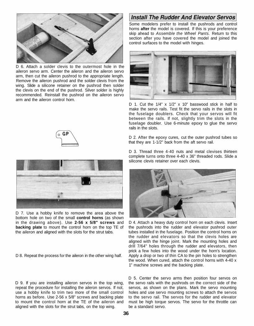
D 6. Attach a solder clevis to the outermost hole in theaileron servo arm. Center the aileron and the aileron servoarm, then cut the aileron pushrod to the appropriate length.Remove the aileron pushrod and the solder clevis from thewing. Slide a silicone retainer on the pushrod then solderthe clevis on the end of the pushrod. Silver solder is highlyrecommended. Reinstall the pushrod on the aileron servoarm and the aileron control horn.
Some modelers prefer to install the pushrods and controlhorns after the model is covered. If this is your preferenceskip ahead to Assemble the Wheel Pants. Return to thissection after you have covered the model and joined thecontrol surfaces to the model with hinges.
D 7. Use a hobby knife to remove the area above thebottom hole on two of the small control horns (as shownin the drawing above). Use 2-56 x 5/8" screws andbacking plate to mount the control horn on the top TE ofthe aileron and aligned with the slots for the strut tabs.
D 8. Repeat the process for the aileron in the other wing half.
D 9. If you are installing aileron servos in the top wing,repeat the procedure for installing the aileron servos. If not,use a hobby knife to trim two more of the small controlhorns as before. Use 2-56 x 5/8" screws and backing plateto mount the control horn at the TE of the aileron andaligned with the slots for the strut tabs, on the top wing.
D 1. Cut the 1/4" x 1/2" x 10" basswood stick in half tomake the servo rails. Test fit the servo rails in the slots inthe fuselage doublers. Check that your servos will fitbetween the rails. If not, slightly trim the slots in thefuselage doubler. Use 6-minute epoxy to glue the servorails in the slots.
D 2. After the epoxy cures, cut the outer pushrod tubes sothat they are 1-1/2" back from the aft servo rail.
D 3. Thread three 4-40 nuts and metal clevises thirteencomplete turns onto three 4-40 x 36" threaded rods. Slide asilicone clevis retainer over each clevis.
D 4. Attach a heavy duty control horn on each clevis. Insertthe pushrods into the rudder and elevator pushrod outertubes installed in the fuselage. Position the control horns onthe rudder and elevators so that the clevis holes arealigned with the hinge joint. Mark the mounting holes anddrill 7/64" holes through the rudder and elevators, thenprick a few holes into the wood under the horn's location.Apply a drop or two of thin CA to the pin holes to strengthenthe wood. When cured, attach the control horns with 4-40 x1" machine screws and the backing plate.
D 5. Center the servo arms then position four servos onthe servo rails with the pushrods on the correct side of theservos, as shown on the plans. Mark the servo mountingholes and use servo mounting screws to attach the servosto the servo rail. The servos for the rudder and elevatormust be high torque servos. The servo for the throttle canbe a standard servo.
36

D D 3. Test fit the wheel pant halves and makeadjustments where necessary.
D D 4. Join the wheel pant halves by carefully spot gluingthem with thin CA. Glue the top, the front and then the rearwhere the two halves butt together. After the halves arejoined, apply thin CA along the length of all seams.
D 6. Attach a solder clevis to the outermost hole in therudder and elevator servo arms. Center the rudder andelevator servo arms on the servos. Cut the rudder andelevator pushrods to the appropriate length. Remove thepushrods and the solder clevis from the fuselage and slidea silicone retainer on the pushrod, then solder the clevis onthe pushrod. Reinstall the pushrods and attach the clevisesto the servo arms and control horns.
Note: Do not use CA accelerator. Use of accelerator on theABS plastic may cause cracks and/or prevent paint fromadhering.
D 7. Position the tail wheel bracket on the bottom reardeck. Mark the location of the tail wheel wire on the bottomof the rudder. Remove the tail wheel wire and drill a 9/64"hole at the mark. Test fit the tail wheel wire in the rudder.The hole will be slightly larger than the wire. This allows theepoxy to form a sleeve around the wire when it is glued in.
D D 5. Use your hobby knife or a power tool with asanding drum to cut out the wheel opening.
Hint: Make the wheel opening wide as this will makeinstalling the wheel and axle easier and cause lessinterference with the wheel upon landing and takeoff. Youcan see the size of the wheel opening in the followingphoto.
D D 1. Trim one matching set of wheel pant halves alongthe molded cut lines. Notice that the top of the outer pantgoes over the lip of the inner pant and the bottom of theinner pant goes over the lip of the outer pant. You can usea hobby knife to carefully score along the cut lines and flexthe plastic until the excess breaks free, or use smallscissors to cut along the lines. Kyosho curved Lexancutting scissors (KYOR1010) work extremely well for thisand make the job a cinch. For now, don't worry aboutaccurately cutting out the opening in each wheel pant half -just cut an approximate opening for the wheels.
D D 2. Use your bar sander to carefully true the edges ofthe overlapping pieces of the wheel pant halves so whenyou glue them together the seam will be as small andstraight as possible. Notice that the rear of the pant halvesdo not overlap. Use 150 or 220-grit sandpaper to removethe flashing and thoroughly roughen all areas that are tobe glued, including the indentation on the inside of bothinner pant halves.
D D 6. Use medium CA to glue the die-cut 1/16" plywoodwheel pant mount to the inside of each wheel pant.
D D 7. Use a metal file to chamfer the edges and cornersof the aluminum landing gear so it will fit neatly in therecess of the wheel pant. Position the wheel pant on thealuminum landing gear. Use a felt-tip pen to accuratelymark the location of the axle mounting hole.
37

D D 8. Drill a 3/16" hole in the wheel pant at the mark.Back up the wheel pant mount with a piece of plywood soyou do not split it as the drill goes through.
D D 9. If the axle you are using does not fit through thewheel hub of your 4" wheel, enlarge the wheel hub with a3/16" drill bit.
D D 10. Test fit the wheel in the wheel pant using thefollowing procedure.
D D 13. Before painting the wheel pants, fill the seamswith putty filler such as Squadron White Putty or resin fillersuch as Bondo . We use Bondo most of the time as it curesquickly and is easy to sand but usually it must bepurchased in large quantities. Squadron putty works wellbut it takes overnight to dry and usually requires at leasttwo applications because it shrinks as it dries.
D 14. After the filler cures, wet sand the wheel pants with400-grit sandpaper to prepare them for primer.
A. Install a 3/16" wheel collar on the axle followed by thewheel and a second collar.
D 1. The cowl is assembled following the same procedureas the wheel pants. Cut the cowl along the cut lines. Thenuse your bar sander to true all the edges. For now, theopening in the front of the cowl only needs to be roughly cutout. Use coarse sandpaper to roughen the inside of all theoverlapping areas so the glue will stick.
B. Insert the wheel in the pant with the threaded end of theaxle inserted in the plywood wheel pant mount.
Note: When you install the wheel after the wheel pant hasbeen painted, put masking tape on the bottom of the pantto avoid scratching the paint.
D 2. Tape the two pieces together, then wick a smallamount of thin CA into the seams of the overlapping joints.Tape the front of the cowl to the side. Notice that one sideof the cowl front is angled. The angle matches the angle onthe cowl side. Wick CA into the seams of the overlappingjoints. After the CA has cured, remove the tape and makesure you have thoroughly glued the two pieces together byinspecting the glue joints and adding thin CAif necessary.
D D 11. Temporarily mount the wheel pant to the landinggear with the nut supplied with the axle.
D D 12. Perform the same procedure to assemble andtemporally mount the other wheel pant to the landing gear.
D 3. Use a sharp hobby knife or a power tool with asanding drum to accurately cut the engine opening in thefront of the cowl.
38
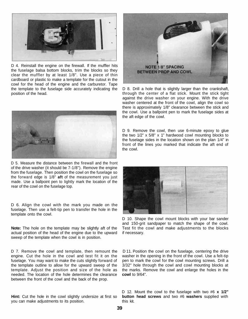
D 4. Reinstall the engine on the firewall. If the muffler hitsthe fuselage balsa bottom blocks, trim the blocks so theyclear the muffler by at least 1/8". Use a piece of thincardboard or plastic to make a template for the cutout in thecowl for the head of the engine and the carburetor. Tapethe template to the fuselage side accurately indicating theposition of the head.
D 8. Drill a hole that is slightly larger than the crankshaft,through the center of a flat stick. Mount the stick tightagainst the drive washer on your engine. With the drivewasher centered at the front of the cowl, align the cowl sothere is approximately 1/8" clearance between the stick andthe cowl. Use a ballpoint pen to mark the fuselage sides atthe aft edge of the cowl.
D 9. Remove the cowl, then use 6-minute epoxy to gluethe two 1/2" x 5/8" x 1" hardwood cowl mounting blocks tothe fuselage sides in the location shown on the plan 1/4" infront of the lines you marked that indicate the aft end ofthe cowl.
D 5. Measure the distance between the firewall and the frontof the drive washer (it should be 7-1/8"). Remove the enginefrom the fuselage. Then position the cowl on the fuselage sothe forward edge is 1/8" aft of the measurement you justmade. Use a ballpoint pen to lightly mark the location of therear of the cowl on the fuselage top.
D 6. Align the cowl with the mark you made on thefuselage. Then use a felt-tip pen to transfer the hole in thetemplate onto the cowl.
Note: The hole on the template may be slightly aft of theactual position of the head of the engine due to the upwardsweep of the template when the cowl is in position.
D 7. Remove the cowl and template, then remount theengine. Cut the hole in the cowl and test fit it on thefuselage. You may want to make the cuts slightly forward ofthe template outline to allow for the upward sweep of thetemplate. Adjust the position and size of the hole asneeded. The location of the hole determines the clearancebetween the front of the cowl and the back of the prop.
D 10. Shape the cowl mount blocks with your bar sanderand 150-grit sandpaper to match the shape of the cowl.Test fit the cowl and make adjustments to the blocksif necessary.
D 11. Position the cowl on the fuselage, centering the drivewasher in the opening in the front of the cowl. Use a felt-tippen to mark the cowl for the cowl mounting screws. Drill a3/32" hole through the cowl and cowl mounting blocks atthe marks. Remove the cowl and enlarge the holes in thecowl to 9/64".
Hint: Cut the hole in the cowl slightly undersize at first soyou can make adjustments to its position.
D 12. Mount the cowl to the fuselage with two #6 x 1/2"button head screws and two #6 washers supplied withthis kit.
39
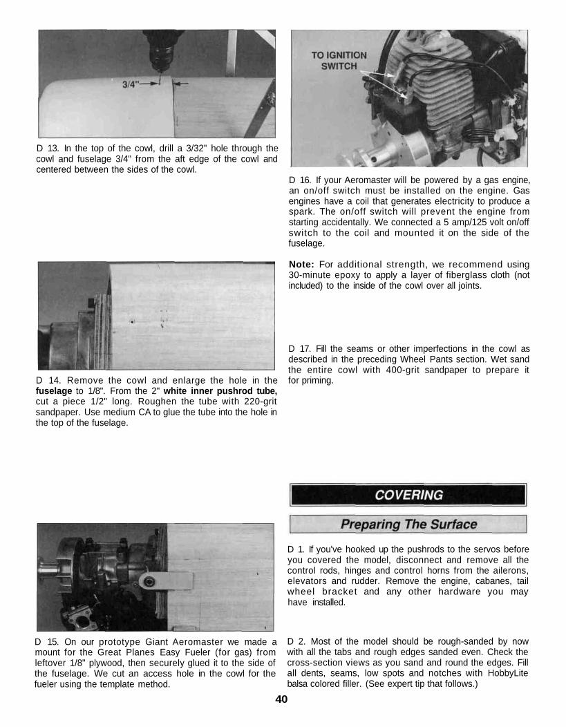
D 13. In the top of the cowl, drill a 3/32" hole through thecowl and fuselage 3/4" from the aft edge of the cowl andcentered between the sides of the cowl.
D 14. Remove the cowl and enlarge the hole in thefuselage to 1/8". From the 2" white inner pushrod tube,cut a piece 1/2" long. Roughen the tube with 220-gritsandpaper. Use medium CA to glue the tube into the hole inthe top of the fuselage.
D 16. If your Aeromaster will be powered by a gas engine,an on/off switch must be installed on the engine. Gasengines have a coil that generates electricity to produce aspark. The on/off switch will prevent the engine fromstarting accidentally. We connected a 5 amp/125 volt on/offswitch to the coil and mounted it on the side of thefuselage.
Note: For additional strength, we recommend using30-minute epoxy to apply a layer of fiberglass cloth (notincluded) to the inside of the cowl over all joints.
D 17. Fill the seams or other imperfections in the cowl asdescribed in the preceding Wheel Pants section. Wet sandthe entire cowl with 400-grit sandpaper to prepare itfor priming.
D 1. If you've hooked up the pushrods to the servos beforeyou covered the model, disconnect and remove all thecontrol rods, hinges and control horns from the ailerons,elevators and rudder. Remove the engine, cabanes, tailwheel bracket and any other hardware you mayhave installed.
D 15. On our prototype Giant Aeromaster we made amount for the Great Planes Easy Fueler (for gas) fromleftover 1/8" plywood, then securely glued it to the side ofthe fuselage. We cut an access hole in the cowl for thefueler using the template method.
D 2. Most of the model should be rough-sanded by nowwith all the tabs and rough edges sanded even. Check thecross-section views as you sand and round the edges. Fillall dents, seams, low spots and notches with HobbyLitebalsa colored filler. (See expert tip that follows.)
40

To remove minor dents in balsa wood, lightly wet thedented area Then, with your sealing iron set on high,lightly iron the dent out If the dent is only minor it shouldcome right out
D 3 After the filler has dried, use progressively finergrades of sandpaper to even and smooth all the edges,seams and surfaces Remove all the balsa dust from themodel with compressed air or a vacuum with a brush and atack cloth.
Top and Bottom Wing:
1 Tips of bottom wing2. Trailing edges of wing and the inboard portion of tips
bottom wing3 Bottom of right, then left panel bottom wing4 Top of right, then left panel bottom wing5 Tips of top wing6 Trailing edges of wing and inboard portion of tips
top wing7 Bottom of right, then left panel of top wing8 Top of right, then left panel top wing9 Aileron tips bottom, then top of aileron
10. Aileron servo hatches
Cover the model with Top Flite MonoKote™ film, using therecommended covering sequence that follows Before youcover the fuselage, first apply 1/4" wide strips of MonoKotefilm in the corners of the stab and fuselage and the fin andthe fuselage then proceed to cover the fin and stab withpre-cut pieces that meet in the corners and overlap the 1/4"strips Never cut the covering on the stab and fin after ithas been applied except around the leading and trailingedges and the tips Modelers who do this may cut throughthe covering and into the stab and fin This will weaken thestructure to a point where it may fail during flight Somemodelers drill a small hole in each rib and the trailing edgeof the elevator and rudder to allow expanded gas to exitwhile heating the MonoKote film This procedure keeps thecovering from "ballooning" and allows you to securely bondit to the entire elevator.
Some modelers prefer to cover the top and bottom of theailerons with one strip of MonoKote film This is done bycovering the bottom first, then wrapping the MonoKote filmup over the leading edge.
Fuselage:1 1/4" strips at fin and stab as described2 Aft fuselage bottom3 Forward fuselage bottom4 Fuselage right side up to the top center of the turtle
deck5 Fuselage left side up to the top center of the turtle deck,
overlapping by 1/8"6 Forward fuselage deck top7 Fin tip, followed by stab tips8 Stab bottom, then top9 Fin right side then left side
10 Elevator tips and root ends11 Elevator bottoms, then tops12. Rudder tips, right side, then left side
After the model is covered, use fuelproof model paint,30-minute epoxy thinned with alcohol or finishing resin tocoat areas that may be exposed to raw fuel or exhaustresidue These are areas such as the firewall, wing saddletripler and the fuel tank compartment.
Top Flite" LustreKote"" fuelproof paint is recommended forpainting all ABS plastic parts and the aluminum landinggear Remove the wheel pants from the landing gear anduse a file to round the corners of the aluminum landing gearbefore you paint it At least one coat of LustreKote primer ishighly recommended to fill all the small scratches left fromsanding as well as small pin holes in the filler Wet sandbetween coats with 400-gnt sandpaper and apply a secondcoat of primer if necessary.
Before painting the canopy, use a scissors or a hobby knifeto trim along the molded cut lines, then true the edges withyour bar sander and 220-grit sandpaper Use 400-gntsandpaper to scuff the frame portion of the canopy so thepaint will stick We recommend you paint the canopy framewith Pactra Formula-U or Chevron Perfect Paint Usemasking tape or frisket film to cover the portion of thecanopy that is not to be painted If you are not sure that thepaint is compatible with the clear canopy, test the paint on aleftover piece of canopy material
For painting the pilot we have discovered that acrylic waterbase paints such as the types found at craft stores workgreat The acryl ic paints look real ist ic on the pilotbecause they are not glossy and best of all, they cleanupwith water.
Paint the cockpit interior using your own imagination Wepainted the back rest instrument panel and the cockpitsides with flat black brush-on paint, then covered thecockpit floor with 600-grit sandpaper glued in place with3M 77 spray adhesive.
41
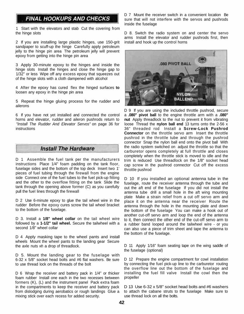
1 Start with the elevators and stab Cut the covering fromthe hinge slots
2 If you are installing large plastic hinges, use 150-gritsandpaper to scuff-up the hinge Carefully apply petroleumjelly to the hinge pin area The petroleum jelly will preventepoxy from getting into the hinge pin area
3 Apply 30-minute epoxy to the hinges and inside thehinge slots Install the hinges and close the hinge gap to1/32" or less Wipe off any excess epoxy that squeezes outof the hinge slots with a cloth dampened with alcohol
4 After the epoxy has cured flex the hinged surfaces toloosen any epoxy in the hinge pin area
5 Repeat the hinge gluing process for the rudder andailerons
6 If you have not yet installed and connected the controlhorns and elevator, rudder and aileron pushrods return to"Install The Rudder And Elevator Servos" on page 36 forinstructions
D 1 Assemble the fuel tank per the manufacturersinstructions Place 1/4" foam padding on the tank floor,fuselage sides and the bottom of the top deck Insert two 1'pieces of fuel tubing through the firewall from the engineside Connect one of the fuel tubes to the fuel pick-up fittingand the other to the overflow fitting on the tank Slide thetank through the opening above former (C) as you carefullypull the fuel lines through the firewall
D 2 Use 6-minute epoxy to glue the tail wheel wire in therudder Before the epoxy cures screw the tail wheel bracketto the bottom of the fuselage.
D 3. Install a 1/8" wheel collar on the tail wheel wirefollowed by a 1-1/2" tail wheel. Secure the tailwheel with asecond 1/8" wheel collar
D 4 Apply masking tape to the wheel pants and installwheels Mount the wheel pants to the landing gear Securethe axle nuts with a drop of threadlock.
D 5. Mount the landing gear to the fuselage with6-32 x 5/8" socket head bolts and #6 flat washers. Be sureto use thread lock on the threads of the bolt
D 6 Wrap the receiver and battery pack in 1/4" or thickerfoam rubber Install one each in the two recesses betweenformers (K), (L) and the instrument panel Pack extra foamin the compartments to keep the receiver and battery packfrom dislodging during aerobatics or rough landings Glue amixing stick over each recess for added security.
D 7 Mount the receiver switch in a convenient location Besure that will not interfere with the servos and pushrodsinside the fuselage
D 8. Switch the radio system on and center the servoarms Install the elevator and rudder pushrods first, theninstall and hook up the control horns
D 9 If you are using the included throttle pushrod, securea .080" pivot ball to the engine throttle arm with a .080"nut Apply threadlock to the nut to prevent it from vibratingloose Thread the nylon ball end 13 turns onto the 2-56 x36" threaded rod Install a Screw-Lock PushrodConnector on the throttle servo arm Insert the throttlepushrod in the throttle tube and through the pushrodconnector Snap the nylon ball end onto the pivot ball Withthe radio system switched on adjust the throttle so that thecarburetor opens completely at full throttle and closescompletely when the throttle stick is moved to idle and thetrim is reduced Use threadlock on the 1/8" socket headcap screw in the pushrod connector Cut off the excessthrottle pushrod
D 10 If you installed an optional antenna tube in thefuselage, route the receiver antenna through the tube andout the aft end of the fuselage If you did not install theantenna tube drill a small hole in the aft wing mountingplate Make a strain relief from a cut off servo arm andplace it on the antenna near the receiver Route theantenna through the hole in the mounting plate and downthe bottom of the fuselage You can make a hook out ofanother cut-off servo arm and loop the end of the antennato it, then connect the other end of the cut-off servo arm toa rubber band looped around the tailwheel wire - or youcan also use a piece of trim sheet and tape the antenna tothe bottom of the fuselage.
D 11 Apply 1/16" foam seating tape on the wing saddle ofthe fuselage (optional)
D 12 Prepare the engine compartment for cowl installationby connecting the fuel pick-up line to the carburetor routingthe overflow line out the bottom of the fuselage andinstalling the fuel fill valve Install the cowl then thepropeller
D 13 Use 6-32 x 5/8" socket head bolts and #6 washersto attach the cabane struts to the fuselage Make sure touse thread lock on all the bolts.
42
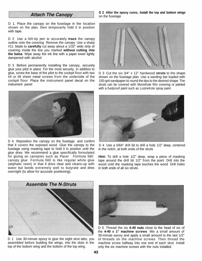
D 2 After the epoxy cures, install the top and bottom wingson the fuselage
D 1. Place the canopy on the fuselage in the locationshown on the plan, then temporarily hold it in positionwith tape.
D 2 Use a felt-tip pen to accurately trace the canopyoutline onto the covering Remove the canopy Use a sharp#11 blade to carefully cut away about a 1/32" wide strip ofcovering inside the line you marked without cutting intothe balsa Wipe away the ink line with a paper towel lightlydampened with alcohol
D 3 Before permanently installing the canopy, securelyglue your pilot in place For the most security, in addition toglue, screw the base of the pilot to the cockpit floor with two#4 or #6 sheet metal screws from the underside of thecockpit floor Place the instrument panel decal on theinstrument panel
D 3 Cut the six 3/4" x 12" hardwood struts to the shapeshown on the fuselage plan Use a sanding bar loaded with150-grit sandpaper to round the tips to the desired shape Thestruts can be covered with MonoKote film covering or paintedwith a fuelproof paint such as LustreKote spray paint
D 4. Reposition the canopy on the fuselage and confirmthat it covers the exposed wood Glue the canopy to thefuselage using masking tape to hold it in position until theglue dries We recommend a glue specifically formulatedfor gluing on canopies such as Pacer Formula 560canopy glue Formula 560 is like regular white glue(aliphatic resin) in that it dries clear and cleans-up withwater but bonds extremely well to butyrate and driesovernight (to allow for accurate positioning).
D 4 Use a 5/64" drill bit to drill a hole 1/2" deep, centeredin the notch, at both ends of the struts
Hint: To drill a hole 1/2" deep, wrap a piece of maskingtape around the drill bit 1/2" from the point Drill into thewood until the masking tape touches the wood Drill holesin both ends of all six struts.
D 1 Use 30-minute epoxy to glue the eight strut tabs, youassembled before building the wings, into the slots in thetop of the bottom wing and the bottom of the top wing.
D 5 Thread the six 4-40 nuts close to the head of six ofthe 4-40 x 1" machine screws Mix a small amount of30-minute epoxy and apply a small amount to the last 1/2"of threads on the machine screws Then thread themachine screw halfway into one end of each strut Installonly the six machine screws with the nuts installed.
43
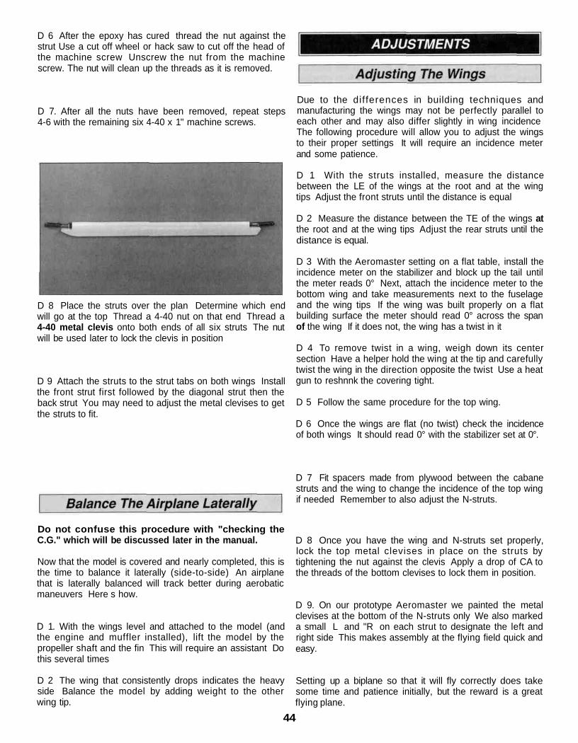
D 6 After the epoxy has cured thread the nut against thestrut Use a cut off wheel or hack saw to cut off the head ofthe machine screw Unscrew the nut from the machinescrew. The nut will clean up the threads as it is removed.
D 7. After all the nuts have been removed, repeat steps4-6 with the remaining six 4-40 x 1" machine screws.
D 8 Place the struts over the plan Determine which endwill go at the top Thread a 4-40 nut on that end Thread a4-40 metal clevis onto both ends of all six struts The nutwill be used later to lock the clevis in position
D 9 Attach the struts to the strut tabs on both wings Installthe front strut first followed by the diagonal strut then theback strut You may need to adjust the metal clevises to getthe struts to fit.
Due to the differences in building techniques andmanufacturing the wings may not be perfectly parallel toeach other and may also differ slightly in wing incidenceThe following procedure will allow you to adjust the wingsto their proper settings It will require an incidence meterand some patience.
D 1 With the struts installed, measure the distancebetween the LE of the wings at the root and at the wingtips Adjust the front struts until the distance is equal
D 2 Measure the distance between the TE of the wings atthe root and at the wing tips Adjust the rear struts until thedistance is equal.
D 3 With the Aeromaster setting on a flat table, install theincidence meter on the stabilizer and block up the tail untilthe meter reads 0° Next, attach the incidence meter to thebottom wing and take measurements next to the fuselageand the wing tips If the wing was built properly on a flatbuilding surface the meter should read 0° across the spanof the wing If it does not, the wing has a twist in it
D 4 To remove twist in a wing, weigh down its centersection Have a helper hold the wing at the tip and carefullytwist the wing in the direction opposite the twist Use a heatgun to reshnnk the covering tight.
D 5 Follow the same procedure for the top wing.
D 6 Once the wings are flat (no twist) check the incidenceof both wings It should read 0° with the stabilizer set at 0°.
D 7 Fit spacers made from plywood between the cabanestruts and the wing to change the incidence of the top wingif needed Remember to also adjust the N-struts.
Do not confuse this procedure with "checking theC.G." which will be discussed later in the manual.
Now that the model is covered and nearly completed, this isthe time to balance it laterally (side-to-side) An airplanethat is laterally balanced will track better during aerobaticmaneuvers Here s how.
D 8 Once you have the wing and N-struts set properly,lock the top metal clevises in place on the struts bytightening the nut against the clevis Apply a drop of CA tothe threads of the bottom clevises to lock them in position.
D 1. With the wings level and attached to the model (andthe engine and muffler installed), lift the model by thepropeller shaft and the fin This will require an assistant Dothis several times
D 2 The wing that consistently drops indicates the heavyside Balance the model by adding weight to the otherwing tip.
D 9. On our prototype Aeromaster we painted the metalclevises at the bottom of the N-struts only We also markeda small L and "R on each strut to designate the left andright side This makes assembly at the flying field quick andeasy.
Setting up a biplane so that it will fly correctly does takesome time and patience initially, but the reward is a greatflying plane.
44
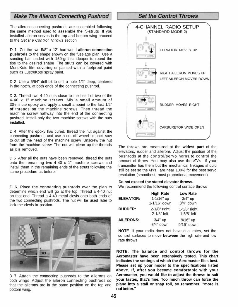
The aileron connecting pushrods are assembled followingthe same method used to assemble the N-struts If youinstalled aileron servos in the top and bottom wing proceedto the Set the Control Throws section
D 1 Cut the two 5/8" x 12" hardwood aileron connectionpushrods to the shape shown on the fuselage plan Use asanding bar loaded with 150-grit sandpaper to round thetips to the desired shape The struts can be covered withMonoKote film covering or painted with a fuelproof paintsuch as LustreKote spray paint.
D 2 Use a 5/64" drill bit to drill a hole 1/2" deep, centeredin the notch, at both ends of the connecting pushrod.
D 3. Thread two 4-40 nuts close to the head of two of the4-40 x 1" machine screws Mix a small amount of30-minute epoxy and apply a small amount to the last 1/2"of threads on the machine screws Then thread themachine screw halfway into the end of the connectingpushrod Install only the two machine screws with the nutsinstalled.
D 4 After the epoxy has cured, thread the nut against theconnecting pushrods and use a cut-off wheel or hack sawto cut off the head of the machine screw Unscrew the nutfrom the machine screw The nut will clean up the threadsas it is removed.
D 5 After all the nuts have been removed, thread the nutsonto the remaining two 4 40 x 1" machine screws andinstall them in the remaining ends of the struts following thesame procedure as before.
D 6. Place the connecting pushrods over the plan todetermine which end will go at the top Thread a 4-40 nuton that end Thread a 4-40 metal clevis onto both ends ofthe two connecting pushrods. The nut will be used later tolock the clevis in position.
D 7 Attach the connecting pushrods to the ailerons onboth wings Adjust the aileron connecting pushrods sothat the ailerons are in the same position on the top andbottom wing.
ELEVATOR MOVES UP
RIGHT AILERON MOVES UP
LEFT AILERON MOVES DOWN
RUDDER MOVES RIGHT
CARBURETOR WIDE OPEN
The throws are measured at the widest part of theelevators, rudder and ailerons Adjust the position of thepushrods at the control /servo horns to control theamount of throw You may also use the ATV's if yourtransmitter has them but the mechanical linkages shouldstill be set so the ATV's are near 100% for the best servoresolution (smoothest, most proportional movement)
Do not exceed the stated elevator throws.We recommend the following control surface throws
High Rate Low Rate3/4" up
3/4" down1-5/8" right1-5/8" left9/16" up
9/16" down
1-1/16" up1-1/16" down
ELEVATOR:
RUDDER:
AILERONS:
2-1/8" right2-1/8" left
3/4" up3/4" down
NOTE If your radio does not have dual rates, set thecontrol surfaces to move between the high rate and lowrate throws
NOTE: The balance and control throws for theAeromaster have been extensively tested. This chartindicates the settings at which the Aeromaster flies best.Please set up your model to the specifications listedabove. If, after you become comfortable with yourAeromaster, you would like to adjust the throws to suityour tastes, that's fine. Too much throw can force theplane into a stall or snap roll, so remember, "more isnot better."
4-CHANNEL RADIO SETUP(STANDARD MODE 2)
45
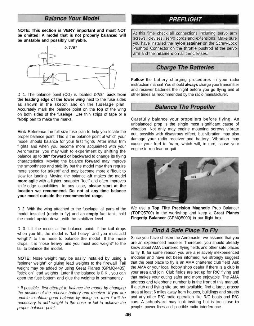
NOTE: This section is VERY important and must NOTbe omitted! A model that is not properly balanced willbe unstable and possibly unflyable.
D 1. The balance point (CG) is located 2-7/8" back fromthe leading edge of the lower wing next to the fuse sidesas shown in the sketch and on the fuselage planAccurately mark the balance point on the top of the wingon both sides of the fuselage Use thin strips of tape or afelt-tip pen to make the marks.
Hint: Reference the full size fuse plan to help you locate theproper balance point This is the balance point at which yourmodel should balance for your first flights After initial trimflights and when you become more acquainted with yourAeromaster, you may wish to experiment by shifting thebalance up to 3/8" forward or backward to change its flyingcharacteristics Moving the balance forward may improvethe smoothness and stability but the model may then requiremore speed for takeoff and may become more difficult toslow for landing Moving the balance aft makes the modelmore agile with a lighter, snappier "feel" and often improvesknife-edge capabilities In any case, please start at thelocation we recommend. Do not at any time balanceyour model outside the recommended range.
D 2 With the wing attached to the fuselage, all parts of themodel installed (ready to fly) and an empty fuel tank, holdthe model upside down, with the stabilizer level.
D 3. Lift the model at the balance point. If the tail dropswhen you lift, the model is "tail heavy" and you must addweight* to the nose to balance the model If the nosedrops, it is "nose heavy' and you must add weight* to thetail to balance the model.
NOTE: Nose weight may be easily installed by using a"spinner weight" or gluing lead weights to the firewall Tailweight may be added by using Great Planes (GPMQ4485)"stick on" lead weights Later if the balance is 0 K , you canopen the fuse bottom and glue the weights in permanently
* If possible, first attempt to balance the model by changingthe position of the receiver battery and receiver If you areunable to obtain good balance by doing so, then it w i l l benecessary to add weight to the nose or tail to achieve theproper balance point.
At this time check all connections including servo armscrews, clevises, servo cords and extensions Make sureyou have installed the nylon retainer on the Screw-LockPushrod Connector on the throttle pushrod at the servoarm and the retainers on all the clevises.
Follow the battery charging procedures in your radioinstruction manual You should always charge your transmitterand receiver batteries the night before you go flying and atother times as recommended by the radio manufacturer.
Carefully balance your propellers before flying. Anunbalanced prop is the single most significant cause ofvibration Not only may engine mounting screws vibrateout, possibly with disastrous effect, but vibration may alsodamage your radio receiver and battery. Vibration maycause your fuel to foam, which will, in turn, cause yourengine to run lean or quit
We use a Top Flite Precision Magnetic Prop Balancer(TOPQ5700) in the workshop and keep a Great PlanesFingertip Balancer (GPMQ5000) in our flight box.
Since you have chosen the Aeromaster we assume that youare an experienced modeler Therefore, you should alreadyknow about AMA chartered flying fields and other safe placesto fly If, for some reason you are a relatively inexperiencedmodeler and have not been informed, we strongly suggestthat the best place to fly is an AMA chartered club field Askthe AMA or your local hobby shop dealer if there is a club inyour area and join Club fields are set up for R/C flying andthat makes your outing safer and more enjoyable The AMAaddress and telephone number is in the front of this manual.If a club and flying site are not available, find a large, grassyarea at least 6 miles away from houses, buildings and streetsand any other R/C radio operation like R/C boats and R/Ccars A schoolyard may look inviting but is too close topeople, power lines and possible radio interference.
46
Inspect your radio installation and confirm that all the controlsurfaces respond correctly to transmitter inputs The engineoperation must also be checked by confirming that the engineidles reliably and transitions smoothly and rapidly to full powerand maintains full power indefinitely The engine mustbe "broken-in" on the ground by running it for at leasttwo tanks of fuel Follow the engine manufacturer'srecommendations for break-in. Make sure all screwsremain tight, that the hinges are secure and that the prop ison tight.
Whenever you go to the flying field, check the operationalrange of the radio before the first flight of the day First, makesure no one else is on you frequency (channel) With yourtransmitter antenna collapsed and the receiver andtransmitter on, you should be able to walk at least 100 feetaway from the model and still have control While you workthe controls have a helper stand by your model and tell youwhat the control surfaces are doing Repeat this test withthe engine running at various speeds with a helper holdingthe model If the control surfaces are not always respondingcorrectly, do not fly! Find and correct the problem first Lookfor loose servo connections or corrosion, loose bolts thatmay cause vibration, a defective on/off switch low batteryvoltage or a defective cell, a damaged receiver antenna, or areceiver crystal that may have been damaged from aprevious crash.
Keep these items away from the prop loose clothing, shirtsleeves, ties, scarfs, long hair or loose objects such aspencils, screwdrivers that may fall out of shirt or jacketpockets into the prop.
Use a "chicken stick," spring or electric starter, followinstructions supplied with the starter or stick Make certainthe glow plug clip or connector is secure so that it will notpop off or otherwise get into the running propeller Whenstarting gasoline engines by hand we recommend wearingthick leather gloves to prevent injury in case the enginebackfires.
Make all engine adjustments from behind the rotatingpropeller
The engine gets hot! Do not touch it during or afteroperation Make sure fuel lines are in good condition so fuelwill not leak onto a hot engine causing a fire
To stop a glow engine, cut off the fuel supply by closing off thefuel line or follow the engine manufacturer's recommen-dations Do not use hands, fingers or any other body part to tryto stop the engine To stop a gasoline powered engine anon/off switch should be connected to the engine coil Do notthrow anything into the propeller of a running engine.
Read and abide by the following Academy of ModelAeronautics Official Safety Code.
NOTE: Failure to follow these safety precautions mayresult in severe injury to yourself and others.
Keep all engine fuel in a safe place, away from high heat,sparks or flames as fuel is very flammable Do not smokenear the engine or fuel, and remember that the engineexhaust gives off a great deal of deadly carbon monoxideDo not run the engine in a closed room or garage If youare running a gasoline powered engine we recommend thatyou carry a small fire extinguisher in your field box.
Get help from an experienced pilot when learning tooperate engines Because of the size and power of theGiant Aeromaster, an assistant must hold the plane whenstarting the engine.
Use safety glasses when starting or running engines.
Do not run the engine in an area of loose gravel or sand;the propeller may throw such material in your face or eyes.
Keep your face and body as well as all spectators awayfrom the plane of rotation of the propeller as you start andrun the engine.
1 I will not fly my model aircraft in sanctioned events airshows, or model flying demonstrations until it has been provento be airworthy by having been previously successfullyflight tested
2. I will not fly my model aircraft higher than approximately400 feet within 3 miles of an airport without notifying theairport operator I will give right of way to and avoid flying inthe proximity of full-scale aircraft Where necessary anobserver shall be used to supervise flying to avoid havingmodels fly in the proximity of full-scale aircraft.
3 Where established I will abide by the safety rules forthe flying site I use and I will not willfully and deliberately flymy models in a careless, reckless and/or dangerousmanner.
7. I will not fly my model unless it is identified with myname and address or AMA number, on or in the model.
9. I will not operate models with pyrotechnics (any devicethat explodes, burns, or propels a projectile of any kind).
47

1 I will have completed a successful radio equipmentground check before the first flight of a new or repairedmodel.
2 I will not fly my model aircraft in the presence ofspectators until I become a qualified flier, unless assistedby an experienced helper.
3. I will perform my initial turn after takeoff away from thepit or spectator areas and I will not thereafter fly over pit orspectator areas, unless beyond my control
4 I will operate my model using only radiocontrol frequencies currently allowed by the FederalCommunications Commission.
Takeoff on "high" rates if you have dual rates on yourtransmitter - especially if you are taking off into acrosswind For all models it is good practice to gain asmuch speed as the length of the runway will permit beforelifting off This will give you a safety margin in case theengine quits When you initially advance the throttle and thetail begins to lift, the Aeromaster will begin to turn to the left(due to the torque of the engine-a characteristic of alltaildraggers) Be prepared for this by applying sufficientright rudder to keep the Aeromaster running straight downthe middle of the runway The left turning tendency willdecrease as the plane picks up speed Be sure to allow thetail to rise off the ground before lifting the model into the airDepending on the surface you are taking off from, you willneed to apply little or no up elevator until flying speed isreached Don't hold the tail on the ground with too much upelevator, as the Aeromaster wi l l become airborneprematurely and may stall When the plane has gainedenough f lying speed to safely l i f t o f f , gradually andsmoothly apply up elevator and allow the model to climb ata shallow angle (do not yank the model off the ground intoa steep climb').
CAUTION (THIS APPLIES TO ALL R/C AIRPLANES) If,while flying, you notice any unusual sounds, such as alow-pitched "buzz", this may indicate control surface"flutter" Because flutter can quickly destroy componentsof your airplane, any time you detect flutter you mustimmediately cut the throttle and land the airplane'Check all servo grommets for deterioration (this mayindicate which surface fluttered) and make sure allpushrod linkages are slop-free If it fluttered once, it willprobably flutter again under similar circumstances unlessyou can eliminate the slop or flexing in the linkages Hereare some things which can result in flutter Excessivehinge gap, Not mounting control horns solidly, Sloppy fitof clevis pin in horn, Elasticity present in flexible plasticpushrods, Side-play of pushrod in guide tube caused bytight bends, Sloppy fit of Z-bend in servo arm, Insufficientglue used when gluing in the elevator joiner wire oraileron torque rod, Excessive flexing of aileron, causedby using too soft balsa, Excessive "play" or "backlash" inservo gears, and Insecure servo mounting
The Great Planes Giant Aeromaster is a great-flyinglarge-scale sport model that flies smoothly and predictably, yetis highly acrobatic The Aeromaster does not, however,possess the self-recovery characteristics of a primary R/Ctrainer and should only be flown by experienced RC pilotsThis plane is fully capable of performing a full range ofaerobatics - from simple loops and rolls to impressiveLomcevaks The Aeromaster is limited only by your abilitiesand imagination Have funi
We recommend that you take it easy with your Aeromasterfor the first several flights, gradually 'getting acquainted withthis great sport model as your engine gets fully broken in Ifyou feel as though you have your hands full, keep this inmind pull back on the throttle stick to slow the modeldown This will make everything happen a little slower andallow yourself time to think and react Add and practice onemaneuver at a time learning how the Aeromaster behaves ineach For smooth flying and normal maneuvers, use the lowrate settings as listed on page 45 High rate elevator may berequired for crisp snap rolls and spins For good knife-edgeperformance forward fight speed is the key
Sometime well before it's time to land you should climbyour Aeromaster to a safe altitude and cut the throttle to anidle and check out the model's low speed characteristics.Do this a few times so you know what to expect uponlanding
When i ts time to land, f ly a normal landing pattern andapproach Keep a few clicks of power on until you are overthe runway threshold For your first few landings, plan to landslightly faster than stall speed and on the main wheels, asthis is the easiest way to land your Aeromaster Later, with alittle practice, you will find you can make slow 3-pomtlandings.
Have a ball! But always remember to think about yournext move and plan each maneuver before you do it.Impulsively "jamming the sticks" without any thoughtis what gets most fliers in trouble rather than lack offlying skill. Happy Landings!
48
A model is not a static object Unlike a car, which can only huntleft or right on the road (technically a car does yaw in corners andpitches when the brakes are applied) a plane moves through thatfluid we call air in all directions simultaneously The plane maylook like it's going forward but it could also be yawing slightly,slipping a little and simultaneously climbing or diving a bit. Thecontrols interact Yaw can be a rudder problem, a lateral balanceproblem or an aileron rigging problem We must make manyflights, with minor changes between each, to isolate and finallycorrect the problem.
The chart accompanying this article is intended to serve as ahandy field reference when trimming your model Laminate it inplastic and keep it in your flight box You just might have need toconsult it at the next contest ' The chart is somewhat self-explanatory, but we will briefly run through the salient pointsFirst, we are assuming that the model has been C G balancedaccording to the manufacturer s directions There s nothing sacredabout that spot — frankly it only reflects the balance point wherea prototype model handled the way the guy who designed itthought it should If your model s wing has a degree more or lessof incidence then the whole balance formula is incorrect for you.But, it's a good ballpark place to start.
The second assumption is that the model has been balancedlaterally Wrap a strong string or monofilament around the propshaft behind the spinner then tie the other end to the tail wheel orto a screw driven into the bottom of the aft fuse Make the stringinto a bridle harness and suspend the entire model inverted (yes,with the wing on1) If the right wing always drops, sink somescrews or lead into the left wing tip, etc You may be surprised tofind out how much lead is needed.
At this point the model is statically trimmed It's only a startingpoint, so don't be surprised if you wind up changing it all Oneother critical feature is that the ailerons must have their hinge gapsealed If shoving some Scotch tape or MonoKote into the hingegap to prevent the air from slipping from the top of the wing to thebottom and vice-versa, bothers you, then don't do it.
To achieve the maximum lateral trim on the model, the hinge gapon the ailerons should be sealed The easiest way to do this is todisconnect the aileron linkages and fold the ailerons as far overthe top of the wing as possible (assuming they are top or centerhinged) Apply a strip of clear tape along the joint line. When theaileron is returned to neutral the tape will be invisible and the gapwill be effectively sealed Depending on how big the ailerons are,and how large a gaping gap you normally leave when you installhinges you could experience a 20 percent increase in aileroncontrol response just by this simple measure
Your first flights should be to ascertain control centering andcontrol feel Does the elevator always come back to neutral after a180-degree turn or Split-S? Do the ailerons tend to hunt a littleafter a rolling maneuver? Put the plane through its paces Controlcentering is either a mechanical thing (binding servos, stifflinkages, etc), an electronic thing (bad servo resolution or dead-band in the radio system), or C.G. (aft Center of Gravity will make
the plane wander a bit) The last possibility will be obvious, butdon't continue the testing until you have isolated the problem andcorrected it.
Let's get down to the task of trimming the model. Use thetachometer every time you start the engine to insure consistentresults These trim flights must be done in calm weather Any windwill only make the model weather-vane Each "maneuver" on thelist assumes that you will enter it dead straight-and-level Thewings must be perfectly flat, or else the maneuver will not becorrect and you II get a wrong interpretation. That's where yourobserver comes in Instruct him to be especially watchful of thewings as you enter the maneuvers
Do all maneuvers at full throttle The only deviation from this is ifthe plane will be routinely flown through maneuvers at a differentpower setting
Let's commence with the "engine thrust angle" on the chart. Notethat the observations you make can also be caused by the C.G , sobe prepared to change both to see which gives the desired resultSet up a straight-and-level pass The model should be almosthands-off Without touching any other control on the transmitter,suddenly chop the throttle Did the nose drop9 When you addpower again, did the nose pitch up a bit7 If so you need somedownthrust, or nose weight. When the thrust is correct, the modelshould continue along the same flight path for at least a dozenplane lengths before gravity starts to naturally bring it down
Do each maneuver several times, to make sure that you aregetting a proper diagnosis Often, a gust, an accidental nudge onthe controls, or just a poor maneuver entry can mislead you Thethrust adjustments are a real pain to make On most models, itmeans taking the engine out, adding shims, then reassemblingthe whole thing. Don't take shortcuts Don t try to proceed with theother trim adjustments until you have the thrust line and/or C Gcorrect They are the basis upon which all other trim settingare made.
Also, while you have landed, take the time to crank the clevisesuntil the transmitter trims are at neutral Don't leave the airplane sothat the transmitter has some odd ball combination of trim settingsOne bump of the transmitter and you have lost everything The trimmust be repeatable, the only sure way to do this is to always startwith the transmitter control trims at the middle.
The next maneuver is somewhat more tricky than it looks Toverify the C G , we roll the model up to a 45 degree bank, thentake our hands of f the controls The model should go areasonable distance with the fuse at an even keel If the nosepitches down remove some nose weight and the opposite if thenose pitches up The trick is to use only the ailerons to get themodel up at a 45-degree bank We almost automatically startfeeding in elevator, but that's a no no Do the bank in bothdirections, just to make sure that you are getting an accuratereading of the longitudinal balance.
We now want to test the correct alignment of both sides of theelevator (even if they aren't split, like a Pattern ship's they canstill be warped or twisted). Yaw and lateral balance will also come
49

into play here so be patient and eliminate the variables one-by-one The maneuver is a simple loop but it must be entered withthe wings perfectly level Position the maneuver so that yourassistant can observe it end on Always loop into the wind Doseveral loops see if the same symptom persists Note if themodel loses heading on the front or back side of the loop If youlose it on the way up it s probably an aileron problem while a lossof heading on the way back down is most likely a rudder situationAfter you get the inside loops going correctly do the samemaneuver to the outside entering from an inverted positionBefore you make too many dramatic changes glance at theremainder of the chart and note the myriad combination of thingswe can do just with the ailerons Each change you make will affectall other variables'Note that the Yaw test is the same looping sequences Here,however we are altering rudder and ailerons instead of theelevator halves We must repeat that many airplanes just will notachieve adequate lateral trim without sealing the hinge gaps shutThe larger you make the loops (to a point), the more discernablethe errors will be
why a plane flies the way it does, and you'll be a better pilot for itOne thing we almost guarantee is that your planes will be morereliable and predictable when they are properly trimmed out Theywill fly more efficiently and be less prone to doing radical andsurprising things Your contest scores should improve, too.
We wish to acknowledge the Orlando, Florida, club newsletter,from which the basics of the chart presented here were gleaned
Reprinted in part by Great Planes Model Manufacturing Companycourtesy of Scale R/C Modeler magazine, Pat Potega, Editor,August 1983 issue
Building Notes:
The Lateral Balance test has us pulling those loops very tightlyActually we prefer the Hammerhead as a better test for a heavywing Pull straight up into a vertical and watch which wing dropsA true vertical is hard to do, so make sure that your assistant isobserving from another vantage point Note that the engine torquewill affect the vertical fall off, as will rudder errors Even though webalance the wing statically before leaving for the field, we are nowtrimming it dynamically
The Ai leron Coupling (or rigging) is also tested by doingHammerheads This time however we want to observe the sideview of the model Does the plane want to tuck under a bit9 If so,then try trimming the ailerons down a small bit so that they willact as flaps If the model tends to want to go over into a loop thenrig both ailerons up a few turns on the clevises Note thatdrooping the ailerons will tend to cancel any washout you have inthe wing On some models the lack of washout can lead to somenasty characteristics at low speeds
The effects noted with the Aileron Coupling tests can also becaused by an improperly set wing incidence The better test forthis is knife edge flight If the model tends to pull upward, i e , itswings toward a nose up direction, then reduce the wingincidence If the model tries to go off heading toward the bottomside of the plane, then increase incidence
Again, we reiterate that all of these controls are interactive Whenyou change the wing incidence, it will influence the way theelevator trim is at a given C G Re trimming the wing will alsochange the rigging on the ailerons, in effect and they may have tobe readjusted accordingly
The whole process isn't hard As a matter of fact it's rather fun —but very time consuming It s amazing what you will learn about
50

TRIM FEATURE
CONTROLCENTERING
CONTROLTHROWS
ENGINETHRUSTANGLE'
CENTER OFGRAVITYLONGITUDINALBALANCE
YAW2
LATERALBALANCE
AILERONRIGGING
MANEUVERSFly general circles andrandom maneuvers
Random maneuvers
From straight flightchop throttle quickly
From level flight roll to45-degree bank andneutralize controls
Into wind, do open loops,using only elevatorRepeat tests doingoutside loops frominverted entry
Into wind, do tight insideloops
With wings level, pullto vertical climb andneutralize controls
OBSERVATIONS
Try for hands off straightand level flight
A Too sensitive, jerkycontrols
B Not sufficient control
A Aircraft continues levelpath for short distance
B Plane pitches nose upC Plane pitches nose
down
A Continues in bank formoderate distance
B Nose pitches upC Nose drops
A Wings are levelthroughout
B Yaws to right in bothinside and outsideloops
C Yaws to left in bothinside and outsideloops
D Yaws right on insides,and left on outsideloops
E Yaws left in insides andright on outside loops
A Wings are level andplane falls to either siderandomly
B Falls off to left in loopsWorsens as loopstighten
C Falls off to right inloops Worsens as loopstighten
same path
inside loopC Nose tends to go to
outside loop
CORRECTIONSReadjust linkages so thatTx trims are centered
If A, change linkages toreduce throws
If B, increase throws
If A, trim is okay
If B, decrease downthrustIf C, increase downthrust
If A, trim is good
If B, add nose weightIf C, remove nose weight
If A, trim is correct
If B, add left rudder trim
If C, add right rudder trim
If D, add left aileron trim
If E, add right aileron trim
If A, trim is correct
If B, add weight to rightwing tip
If C, add weight to leftwing tip
If A, trim is correct
If B raise both aileronsvery slightly
If C, lower both aileronsvery slightly
51
If B, add weight to rightwing tip
If C, add weight to leftwing tip
AILERONRIGGING
With wings level, pullto vertical climb andneutralize controls
A Climb continisame path
B Nose tends to
ies along
goto
If A, trim is correct
If B raise both ailerons
1 Engine thrust angle and C G interact Check both2 Yaw and lateral balance produce similar symptoms Note that fin may be crooked Right and left references are from the plane's vantage point
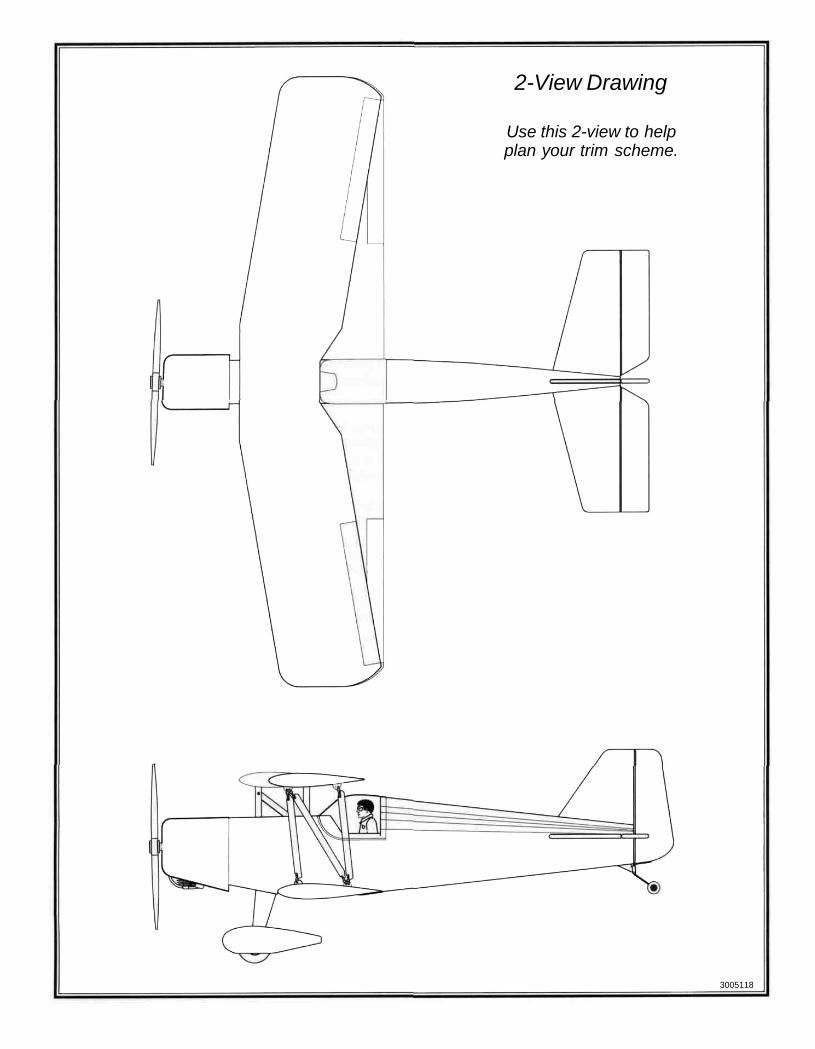
2-View Drawing
Use this 2-view to helpplan your trim scheme.
3005118