instruction manual model dsc720 bollard … · instruction manual model dsc720 bollard terms and...
TRANSCRIPT

INSTRUCTION MANUAL MODEL DSC720 BOLLARD
TERMS AND CONDITIONS / WARRANTY
INSTALLATION
HOOKUP
MECHANICAL THEORY
STARTUP
HYDRAULIC TROUBLE SHOOTING
ELECTRICAL TROUBLE SHOOTING
MAINTENANCE
DRAWINGS
DOCUMENT DSC720 JOB 7584 PORT OF SPAIN, TRINIDAD & TOBAGO
2010 DELTA SCIENTIFIC CORPORATION
CORPORATE HEADQUARTERS40355 Delta LanePalmdale, California 93551Phone: (661) 575-1100Fax: (661) 575-1109Email: [email protected]@deltascientific.comwww.deltascientific.comwww.deltascientific.com
EASTERN REGION U.S.A.125 Wyatt LaneFredericksburg, VA 22406Phone: (703) 541-9114-5-6Fax: (703) 541-9117Email: [email protected]@aol.com

Copyright 2006 Delta Scientific Corporation Page 1 of 1All Rights Reserved Document: Terms and Conditions 092706
TERMS AND CONDITIONS OF PRODUCT SALETHIS PURCHASE CONTRACT (“CONTRACT”) SETS FORTH THE TERMS AND CONDITIONS FOR THE SALE BY DELTA SCIENTIFIC CORPORATION(“DELTA”) TO THE BUYER SPECIFICED HEREIN (“BUYER”) OF THE PRODUCTS SPECIFIED IN THE QUOTATION IDENTIFIED BELOW (THE “PRODUCTS”).THIS CONTRACT DOES NOT CONSTITUTE ACCEPTANCE OF ANY OFFER BY BUYER, WHETHER ORAL OR WRITTEN, INCLUDING BUT NOT LIMITED TOANY PURCHASE ORDER, LETTER, E-MAIL, MEMO, OR ANY OTHER FORM. SALES OF THE PRODUCTS ARE LIMITED SOLELY TO THIS CONTRACT.Acceptance. Buyer accepts these terms and conditions when the first of the following occurs: Buyer (a) signs or makes a written acceptance of this Contract; (b)authorizes production or shipment of any part of the Products; or c) accepts Delta’s Product submittals. Acceptance is expressly limited to all terms and conditionshereof without any addition, modification or exception, and Delta expressly rejects any additional or inconsistent terms, conditions, contingencies or covenantspreviously or hereafter proposed by Buyer. This Contract, when accepted by Delta at its corporate offices in California, constitutes the entire agreement betweenDelta and Buyer, superseding any prior agreement or understanding between the parties with respect to the subject matter hereof.1. Shipment and Delivery. Buyer acknowledges that this Contract, and any additional Buyer orders accepted by Delta hereunder, are firm and non--cancelable.
Deliveries of the Products will be made F.O.B. Delta’s plant at Palmdale, California. Delta will arrange for shipment. Buyer will bear all costs of shipment andinsurance and will reimburse all such costs incurred by Delta when invoiced. Upon Delta’s delivery of the Products at Delta’s plant to any carrier or Buyer’srepresentative, Buyer assumes all risk of loss and damage with respect to the Products. Buyer shall promptly inspect each shipment upon receipt, and shallpromptly inform Delta in the event all Products listed in Delta’s shipping documents do not arrive as scheduled or are damaged or defective.
2. Payment Terms. If credit is approved in advance by Delta, payment terms are net thirty (30) days from the date of invoice. If credit is not approved in advance,Buyer shall make payment in full prior to delivery. Delta’s invoice will be issued and dated upon date of shipment of Products. All payments shall be made atPalmdale, California. Unpaid invoices shall bear interest at the maximum lawful rate or 1.5% per month, whichever is less, commencing upon the date paymentis due. Buyer shall be responsible for all costs of collection, including but not limited to reasonable attorneys’ fees and expenses.
3. Taxes and Similar Charges. Buyer shall bear all applicable federal, state, municipal and other taxes (such as sales, use, excise, ad valorem and similartaxes), customs duties and charges. The lack of any such tax or charge on the invoice shall not affect Buyer’s tax liability.
4. Use and Permits. Buyer will be responsible for operation of Products, including, but not limited to, obtaining all use and export permits, building permits,licenses, certificates and the like, required by any regulatory body for installation and use of the Products. If Buyer wishes for Delta to install any Productspurchased hereunder, the terms and conditions of installation shall be set forth in a separate agreement.
5. Limited Warranty; Limitation of Liability. Delta warrants that during the warranty period applicable to the product, the Products will be free from defect in materialand workmanship. Delta's sole obligation under this warranty shall be to repair (or at Delta's option, to replace), FOB Palmdale, California any defective product, withoutcharge to Buyer, provided that: (a) Buyer gives Delta written notice of any claimed defect within the applicable limited warranty period; (b) the Products, if installed, wereinstalled correctly and in accordance with any instructions provided by Delta, (c) the Products have not been altered, subjected to misuse, negligence or accident, orused with parts not authorized by Delta, (d) the Products have been properly and timely maintained by Buyer in accordance with the preventive maintenanceinstructions provided, and (e) the replaced Product(s) and or part(s) is/are properly removed and returned to Delta, using the Material Return Authorization (MRA)number and information provided by Delta. Product and Product part troubleshooting, diagnosis and/or replacement, and the cost of such replacement installationand/or related remedial services, are the sole responsibility of Buyer. The duration of the applicable Product warranty is ninety (90) days for guard booths, gates, trafficitems and spare parts and one (1) year for Delta’s Barricade/Barrier Systems, from date of shipment. Primer, paint and other surface coatings are excluded fromwarranty. FAILURE BY BUYER TO MAKE TIMELY PAYMENT IN FULL FOR THE PRODUCTS, AND/OR FAILURE BY BUYER TO PROPERLY AND TIMELYCONDUCT PREVENTIVE MAINTENANCE, FAILURE TO FOLLOW DELTA’S INSTRUCTIONS FOR PROBLEM TROUBLESHOOTING AND/OR DIAGNOSIS,AND/OR FAILURE TO PROPERLY INSTALL, REMOVE AND/OR RE-INSTALL A PRODUCT OR PART THEREOF, INVALIDATES THIS WARRANTY. IN THEEVENT A PRODUCT PROBLEM IS NOT THE RESULT OF A PRODUCT DEFECT, BUYER SHALL BE RESPONSIBLE FOR MAINTENANCE CHARGES ATDELTA’S STANDARD TIME AND MATERIALS RATES. NO OTHER WARRANTY IS EXPRESSED AND NONE SHALL BE IMPLIED, INCLUDING WITHOUTLIMITATION THE WARRANTY OF MERCHANTABILITY OR WARRANTY OF FITNESS FOR USE OR FOR A PARTICULAR PURPOSE. THE FOREGOINGSTATES DELTA'S ENTIRE LIABILITY WITH RESPECT TO THE PRODUCTS. IN NO EVENT SHALL DELTA BE LIABLE FOR ANY SPECIAL, INCIDENTAL ORCONSEQUENTIAL DAMAGES WHICH RESULT FROM THE USE OF THE PRODUCTS BY BUYER OR ANY OTHER PARTY, AND IN NO EVENT SHALL DELTA'SLIABILITY EXCEED THE PRICE OF THE PARTICULAR PRODUCT UNIT(S) INVOLVED IN ANY CLAIM.
6. Disclaimer and Indemnification. Buyer acknowledges that the Products, designed for control of vehicular traffic, inherently involve a trade off of risk versusbenefit. Buyer must devote careful consideration to the selection, placement and design of a barricade installation. To ensure approaching vehicles and pedestrians arefully aware of the Barricades and their operation, proper illumination, clearly worded warning signs, auxiliary devices such as semaphore gates, stop-go signal lights,audible warning devices, speed bumps, flashing lights, beacons, etc. should be considered. It is strongly recommended that the Buyer consult an architect and/or atraffic and/or safety engineer prior to installation of a Barricade/Barrier system. Delta does not purport to offer either architectural, traffic or safety engineeringinformation. Buyer also concedes that, beyond its written installation, maintenance and operation instructions, Delta has no control as to how the Products will beutilized, or how persons in the vicinity of the Products, including but not limited to drivers, bicyclists and/or pedestrians, will act. Therefore, Buyer shall holdharmless, indemnify and defend Delta from and against all claims, demands, judgments and awards resulting from Buyer’s use or misuse of the Products,including, but not limited to, claims for personal injury, wrongful death and damage to real or personal property. However, in no event shall this indemnificationprovision apply where Delta’s sole negligence resulted in the claim, judgment or award. Each party shall give the other party prompt written notice of any claimor suit for which such other party is responsible hereunder. The responsible party shall control the defense and/or settlement of such claim; provided thatneither party has the authority to enter into a settlement, make an admission, or undertake any obligation or liability without the other party’s written consent..
7. General. Delta shall not be liable for any delays or failure of performance, beyond the reasonable control of Delta, that affect Delta or any of Delta’s suppliers;including, but not limited to, those caused by acts of God, acts of public enemy, acts or omissions of Buyer or its contractors and sub-contractors, fire, strike,riot, flood, governmental interference, unavailability or shortage of materials, labor, fuel or power through normal commercial channels, or failure or destructionof plant or equipment arising from any cause whatsoever. In the event of delay, the date of delivery shall be extended for a period equal to the time lost by suchdelay, and this Contract shall remain in full force and effect. This Contract may be modified only in writing. This Contract shall be governed by and construed inaccordance with the laws of the state of California. Neither this Contract nor any rights or benefits hereunder are assignable by Buyer without prior writtenconsent of Delta. Any such prohibited assignment shall be null and void. Notices shall be given in writing, via certified or overnight mail with proof of deliver, toan authorized representative or officer of a party.
ACCEPTED BY: ____________________________ DELTA SCIENTIFIC CORP QUOTE NO: _______________________NAME: ____________________________ NAME: _____________________________ REV / DATE: ______________________DATE: ____________________________ DATE: _____________________________

24901 West Avenue Stanford Valencia, California 91355, USA Phone: (661) 257-1800 FAX (661) 257-0617
www.deltascientific.comwww.deltascientific.com
WARRANTY AND LIMITATION OF LIABILITY
Delta Scientific Corporation warrants that during the first one year (365) days after delivery, the Productswill be free from defect in material and workmanship. Delta's sole obligation under this warranty shall beto repair (or at Delta's option, to replace), FOB: Valencia, California, any defective product, without chargeto Buyer, provided that, (a). Buyer gives Delta written notice of any such claimed defect within such periodof one year (365) days, (b). The Products, if installed, were installed by a Delta authorized installer, (c).The Products have not been altered, subjected to misuse, negligence or accident, or used with parts notauthorized by Delta, and (d). The Products have been maintained in accordance with the instructionsprovided. NO OTHER WARRANTY IS EXPRESSED AND NONE SHALL BE IMPLIED, INCLUDINGWITHOUT LIMITATION THE WARRANTY OF MERCHANTABILITY OR WARRANTY OF FITNESSFOR USE OR FOR A PARTICULAR PURPOSE. THE FOREGOING STATES DELTA'S ENTIRELIABILITY WITH RESPECT TO THE PRODUCTS. IN NO EVENT SHALL DELTA BE LIABLE FOR ANYSPECIAL, INCIDENTAL OR CONSEQUENTIAL DAMAGES WHICH RESULT FROM THE USE BYBUYER OR ANY OTHER PARTY, OF THE PRODUCTS, AND IN NO EVENT SHALL DELTA'SLIABILITY EXCEED THE AMOUNTS PAID BY BUYER FOR THE PRODUCTS HEREUNDER.
DISCLAIMER
Please note - careful consideration must be devoted to the selection, placement and design of aBarricade installation. Just as in the case of any Barricade system, perimeter security device or securitygate that blocks a roadway or drive, care must be taken to ensure that approaching vehicles as well aspedestrians are fully aware of the Barricades and their operation. Proper illumination, clearly wordedwarning signs, auxiliary devices such as semaphore gates, stop-go signal lights, audible warning devices,speed bumps, flashing lights, beacons, etc. should be considered. Delta has information available onmany such auxiliary safety equipment not specifically listed herein. It is strongly recommended that anarchitect and/or a traffic and/or safety engineer be consulted prior to installation of a Barricade system.Delta will offer all possible assistance in designing the operating equipment, controls and the overallsystem, but we are not qualified, nor do we purport to offer either traffic or safety engineering information.
INTELLECTUAL PROPERTY, DRAWINGS, SPECIFICATIONS AND TECHNICAL DATA
The drawings and/or data included with this equipment unless otherwise noted remain the confidentialproperty and trade secret of Delta Scientific Corporation. They shall not be disclosed, reproduced or usedfor manufacture, design or construction without the express authorization of Delta Scientific Corporation.The recipient by accepting these drawings and/or data, assumes custody thereof and under the aboveterms agrees not to allow the use of by unauthorized persons.
Copyright 2003 Delta Scientific Corporation Page 1 of 1All Rights Reserved Document Warr-1

Copyright 2001 Delta Scientific Corporation Page 1 of 5All Rights Reserved Document A30000
Page
MECHANICAL INSTALLATION INSTRUCTIONSDELTA BOLLARD SYSTEMS
Safety Precautions
At all times observe good safety practices when working on either the electrical or mechanicalsystem. Particular attention should be paid to the danger of working on the Bollards when thepower is on. The Bollards are powerful presses that can easily crush anything in their way. Keephands free of the mechanism when the power is on or the HPU is up to pressure. Turn off theelectric power and bleed the pressure down to zero before working on any part of the system.Traffic should be controlled around the Bollards during any work so that vehicular accidents do notoccur if the Bollards should happen to rise. After work is complete, do not allow traffic over theBollards until all control and safety functions have been verified to be properly working.
Foundation
The Bollard foundation tubes are to be cast in place. The outside of the Bollard foundation tube isthe form, no additional flashing or forming should be necessary. The excavation for the foundationtubes can be individual for each Bollard in a set or the foundation can be common for all Bollards.We recommend the common foundation as providing the strongest barrier system. See theappropriate foundation drawing in the Drawing Section of the manual. The foundations shown onDelta drawings, unless specially noted, are designed on a soil load bearing factor of 1.5 tons/ft2.Only a very boggy or migrating site would require additional foundation.
Care should be taken to mount the Bollards in an area that is not subject to flooding. Additionally,the roadway should be crowned in the area of the Bollards to prevent standing water from draininginto the Bollard foundation tubes.
It is not necessary for the Bollards to be level or plumb to operate. If the roadway is not level theBollards may be placed to match the contour; however, be sure the appearance factor isconsidered. An installation where the equipment is not level even if it follows the terrain can bedistracting.
The Bollards can be secured in the foundation by leveling with concrete blocks, held to temporarywooden frames, or if desired, steel straps or rolled shapes can be welded to the foundation tubeexteriors to hold a group in alignment during the pour.
Environmental Control
Delta Scientific Corporation's vehicle Bollard systems can be used in all geographical areas.Since the early 1980's, Delta Bollards have been successfully installed in locations just south ofthe Arctic Circle (Oslo and Stockholm), in extremely cold areas of the United States such asIdaho Falls and Grand Forks, and in all the capital cities of Europe. Tropical installations includemore than thirty locations within ten degrees latitude of the Equator. In between, installations runfrom temperate areas to Middle East desert sands.
Copyright 2001 Delta Scientific Corporation Page 2 of 5All Rights Reserved Document A30000
Page
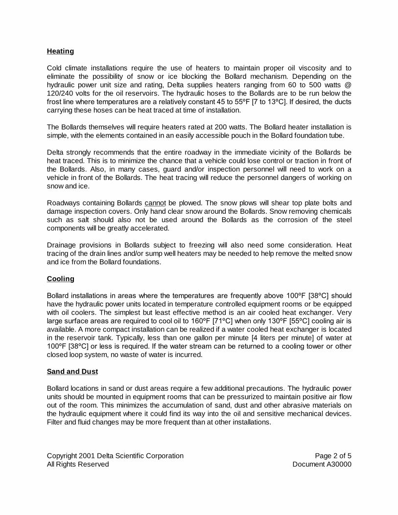
Heating
Cold climate installations require the use of heaters to maintain proper oil viscosity and toeliminate the possibility of snow or ice blocking the Bollard mechanism. Depending on thehydraulic power unit size and rating, Delta supplies heaters ranging from 60 to 500 watts @120/240 volts for the oil reservoirs. The hydraulic hoses to the Bollards are to be run below thefrost line where temperatures are a relatively constant 45 to 55ºF [7 to 13ºC]. If desired, the ductscarrying these hoses can be heat traced at time of installation.
The Bollards themselves will require heaters rated at 200 watts. The Bollard heater installation issimple, with the elements contained in an easily accessible pouch in the Bollard foundation tube.
Delta strongly recommends that the entire roadway in the immediate vicinity of the Bollards beheat traced. This is to minimize the chance that a vehicle could lose control or traction in front ofthe Bollards. Also, in many cases, guard and/or inspection personnel will need to work on avehicle in front of the Bollards. The heat tracing will reduce the personnel dangers of working onsnow and ice.
Roadways containing Bollards cannot be plowed. The snow plows will shear top plate bolts anddamage inspection covers. Only hand clear snow around the Bollards. Snow removing chemicalssuch as salt should also not be used around the Bollards as the corrosion of the steelcomponents will be greatly accelerated.
Drainage provisions in Bollards subject to freezing will also need some consideration. Heattracing of the drain lines and/or sump well heaters may be needed to help remove the melted snowand ice from the Bollard foundations.
Cooling
Bollard installations in areas where the temperatures are frequently above 100ºF [38ºC] shouldhave the hydraulic power units located in temperature controlled equipment rooms or be equippedwith oil coolers. The simplest but least effective method is an air cooled heat exchanger. Verylarge surface areas are required to cool oil to 160ºF [71ºC] when only 130ºF [55ºC] cooling air isavailable. A more compact installation can be realized if a water cooled heat exchanger is locatedin the reservoir tank. Typically, less than one gallon per minute [4 liters per minute] of water at100ºF [38ºC] or less is required. If the water stream can be returned to a cooling tower or otherclosed loop system, no waste of water is incurred.
Sand and Dust
Bollard locations in sand or dust areas require a few additional precautions. The hydraulic powerunits should be mounted in equipment rooms that can be pressurized to maintain positive air flowout of the room. This minimizes the accumulation of sand, dust and other abrasive materials onthe hydraulic equipment where it could find its way into the oil and sensitive mechanical devices.Filter and fluid changes may be more frequent than at other installations.
Copyright 2001 Delta Scientific Corporation Page 3 of 5All Rights Reserved Document A30000
Page
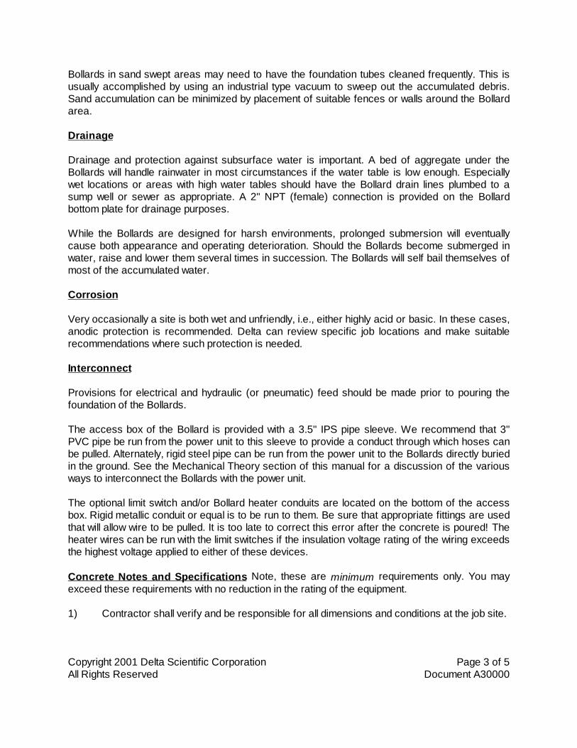
Bollards in sand swept areas may need to have the foundation tubes cleaned frequently. This isusually accomplished by using an industrial type vacuum to sweep out the accumulated debris.Sand accumulation can be minimized by placement of suitable fences or walls around the Bollardarea.
Drainage
Drainage and protection against subsurface water is important. A bed of aggregate under theBollards will handle rainwater in most circumstances if the water table is low enough. Especiallywet locations or areas with high water tables should have the Bollard drain lines plumbed to asump well or sewer as appropriate. A 2" NPT (female) connection is provided on the Bollardbottom plate for drainage purposes.
While the Bollards are designed for harsh environments, prolonged submersion will eventuallycause both appearance and operating deterioration. Should the Bollards become submerged inwater, raise and lower them several times in succession. The Bollards will self bail themselves ofmost of the accumulated water.
Corrosion
Very occasionally a site is both wet and unfriendly, i.e., either highly acid or basic. In these cases,anodic protection is recommended. Delta can review specific job locations and make suitablerecommendations where such protection is needed.
Interconnect
Provisions for electrical and hydraulic (or pneumatic) feed should be made prior to pouring thefoundation of the Bollards.
The access box of the Bollard is provided with a 3.5" IPS pipe sleeve. We recommend that 3"PVC pipe be run from the power unit to this sleeve to provide a conduct through which hoses canbe pulled. Alternately, rigid steel pipe can be run from the power unit to the Bollards directly buriedin the ground. See the Mechanical Theory section of this manual for a discussion of the variousways to interconnect the Bollards with the power unit.
The optional limit switch and/or Bollard heater conduits are located on the bottom of the accessbox. Rigid metallic conduit or equal is to be run to them. Be sure that appropriate fittings are usedthat will allow wire to be pulled. It is too late to correct this error after the concrete is poured! Theheater wires can be run with the limit switches if the insulation voltage rating of the wiring exceedsthe highest voltage applied to either of these devices.
Concrete Notes and Specifications Note, these are minimum requirements only. You mayexceed these requirements with no reduction in the rating of the equipment.
1) Contractor shall verify and be responsible for all dimensions and conditions at the job site.

Copyright 2001 Delta Scientific Corporation Page 4 of 5All Rights Reserved Document A30000
Page
2) Foundation concrete may be placed directly into neat excavations, provided the sides ofthe excavation are stable. Where caving occurs, provide shoring. Type and method ofshoring shall be at the contractor's option.
3) The excavation shall be kept dry at all times. Groundwater, if encountered, shall bepumped from the excavation.
4) Concrete shall be laboratory designed, machine mixed, producing 3,000 psi [20,68 Mpa]at 28 days.
5) Cement shall be tested Portland cement conforming to ASTM C150, Type I or II.
6) Aggregates shall conform to ASTM C33. Maximum size of aggregate shall be 1.5 inch [38MM].
7) Reinforcing steel shall be deformed bars conforming to ASTM A615, Grade 60 (60,000psi [413,7 Mpa]).
8) Hooks and bends shall conform to AIC standard 318, latest revision. Inside diameter ofhooks and bends shall be at least 6 bar diameters.
9) Provide spacer bars, chairs, spreaders, blocks, etc, as required to positively hold the steelin place. All dowels shall be firmly wired in place before concrete is poured.
10) Concrete shall be conveyed from the mixer to final deposit by methods that will preventseparation or loss of materials. Troughs, buckets or the like may be used to conveyconcrete. In no case shall concrete be allowed to free drop more than 5 feet [1,5 M].
11) Concrete shall be thoroughly consolidated by suitable means during placement and shallbe thoroughly worked around reinforcement and embedded fixtures and into corners offorms.
12) Concrete shall be maintained above 50ºF [10ºC] and in a moist condition for at least 7days after placement. Adequate equipment shall be provided for heating concretematerials and protecting concrete during freezing or near freezing weather.
13) Where exterior wall face requires shoring and/or forming, the forms shall be substantialand sufficiently tight to prevent leakage. Forms shall not be removed until the concrete is 7days old.
14) Backfilling shall be done by depositing and tamping into place clean sand or pouring leanconcrete. Water jetting shall not be allowed.
15) Conduits and pipes of aluminum shall not be embedded in concrete unless effectivelycoated or covered to prevent aluminum/concrete reaction or electrolytic action betweenaluminum and steel.

Copyright 2001 Delta Scientific Corporation Page 5 of 5All Rights Reserved Document A30000
Page
16) Construction joints not indicated on the drawings shall not be allowed. Where aconstruction joint is to be made, the surface of concrete shall be thoroughly cleaned andall laitance and standing water removed.
17) Contractor shall be responsible for the protection of all adjacent areas against damageand shall repair or patch all damaged areas to match existing improvements.
18) Contractor shall keep the construction area clean at all times and at completion of workremove all surplus materials, equipment and debris and leave the premises in a cleancondition acceptable to the owner or owner's representative.

DELTA SCIENTIFIC CORPORATION PHONE 661-575-110040355 DELTA LANE FAX 661-575-1109PALMDALE, CALIFORNIA 93551 E-MAIL [email protected]
Copyright 2007 Delta Scientific Corporation Page 1 of 10All Rights Reserved Document A30102.3
ELECTRICAL CONNECTION CHART
NUMBER OF BARRICADES: ONE OR TWO BOLLARD SETS
CONTROL AND OPTIONS: STANDARD 24 VDC CONTROL
MASTER CONTROL PANEL (OPTIONAL)SLAVE CONTROL PANEL (OPTIONAL)EMERGENCY OPERATE CIRCUIT (OPTIONAL)ANNUNCIATOR CIRCUIT (OPTIONAL)SAFETY LOOP DETECTOR, MODEL 3546 (OPTIONAL)STOP/GO SIGNAL LIGHTS, MODEL MPL-10 (OPTIONAL)STOP/GO SIGNAL GATE, MODEL AG812 (OPTIONAL)
REFERENCE CIRCUIT DRAWINGS:
905xx HYDRAULIC POWER UNIT,906x0-2 CONTROL CIRCUIT AND MOTOR STARTER, 120-240/24 VDC,90605 MAIN BOARD LOGIC DIAGRAM907xx MASTER CONTROL PANEL908xx SLAVE CONTROL PANEL90177 SYSTEM INTERCONNECT DIAGRAM, TT200 SERIES BOLLARD BARRIERS
The following charts have been prepared to assist in the ELECTRICAL INTERCONNECT of theHYDRAULIC POWER SYSTEM, THE SYSTEM CONTROL CIRCUITS, THE REMOTECONTROL/STATUS PANELS (MASTER AND SLAVE), AND VARIOUS OPTIONS offered withDELTA BOLLARD SYSTEMS. These CHARTS are designed to supplement the detailed circuitdrawings which are furnished with each system.
The voltage carried by each conductor, unless otherwise specified, is 24 VDC. These conductorsare indicated by this symbol ">>>>>>>>>". The maximum power at this voltage is 250 watts forhot/neutral wires, 1 watt for device wires. Where the voltage is other than 24 VDC, the conductoris indicated by this symbol ">>>>>> * >>>>>>" and a footnote specifies the voltage and currentrequirement. Either multi-conductor cable or single conductor wire can be used at the option of theinstaller. The wire size should be selected based on the pull length, current and voltagerequirements and local codes and specifications.
Terminals are designated by a PCB board number followed by two letters followed by the terminalnumber, i.e. 1 CB 11. The first number is PCB Board number, in this case Bollard Set # 1, the firstletter is the strip location, in this case "control circuit", while the second letter defines the terminalvoltage. `A' and some 'C' codes are low voltage 24 VDC. Some 'B' & 'C' codes are the specifiedlocal control voltage.
DELTA SCIENTIFIC CORPORATION PHONE 661-575-110040355 DELTA LANE FAX 661-575-1109PALMDALE, CALIFORNIA 93551 E-MAIL [email protected]
Copyright 2007 Delta Scientific Corporation Page 2 of 10All Rights Reserved Document A30102.3
ELECTRICAL CONNECTION CHART
************************************************************************************************************
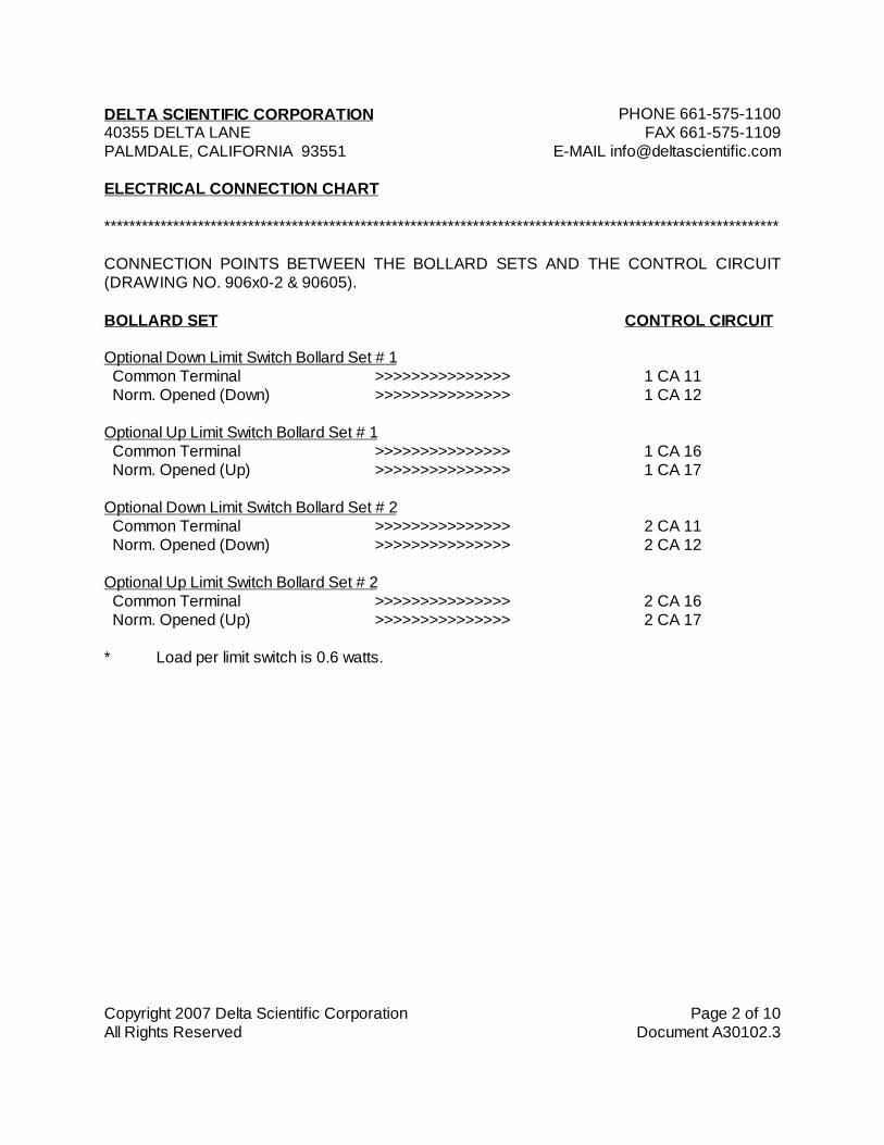
CONNECTION POINTS BETWEEN THE BOLLARD SETS AND THE CONTROL CIRCUIT(DRAWING NO. 906x0-2 & 90605).
BOLLARD SET CONTROL CIRCUIT
Optional Down Limit Switch Bollard Set # 1 Common Terminal >>>>>>>>>>>>>>> 1 CA 11 Norm. Opened (Down) >>>>>>>>>>>>>>> 1 CA 12
Optional Up Limit Switch Bollard Set # 1 Common Terminal >>>>>>>>>>>>>>> 1 CA 16 Norm. Opened (Up) >>>>>>>>>>>>>>> 1 CA 17
Optional Down Limit Switch Bollard Set # 2 Common Terminal >>>>>>>>>>>>>>> 2 CA 11 Norm. Opened (Down) >>>>>>>>>>>>>>> 2 CA 12
Optional Up Limit Switch Bollard Set # 2 Common Terminal >>>>>>>>>>>>>>> 2 CA 16 Norm. Opened (Up) >>>>>>>>>>>>>>> 2 CA 17
* Load per limit switch is 0.6 watts.
DELTA SCIENTIFIC CORPORATION PHONE 661-575-110040355 DELTA LANE FAX 661-575-1109PALMDALE, CALIFORNIA 93551 E-MAIL [email protected]
Copyright 2007 Delta Scientific Corporation Page 3 of 10All Rights Reserved Document A30102.3
ELECTRICAL CONNECTION CHART
************************************************************************************************************
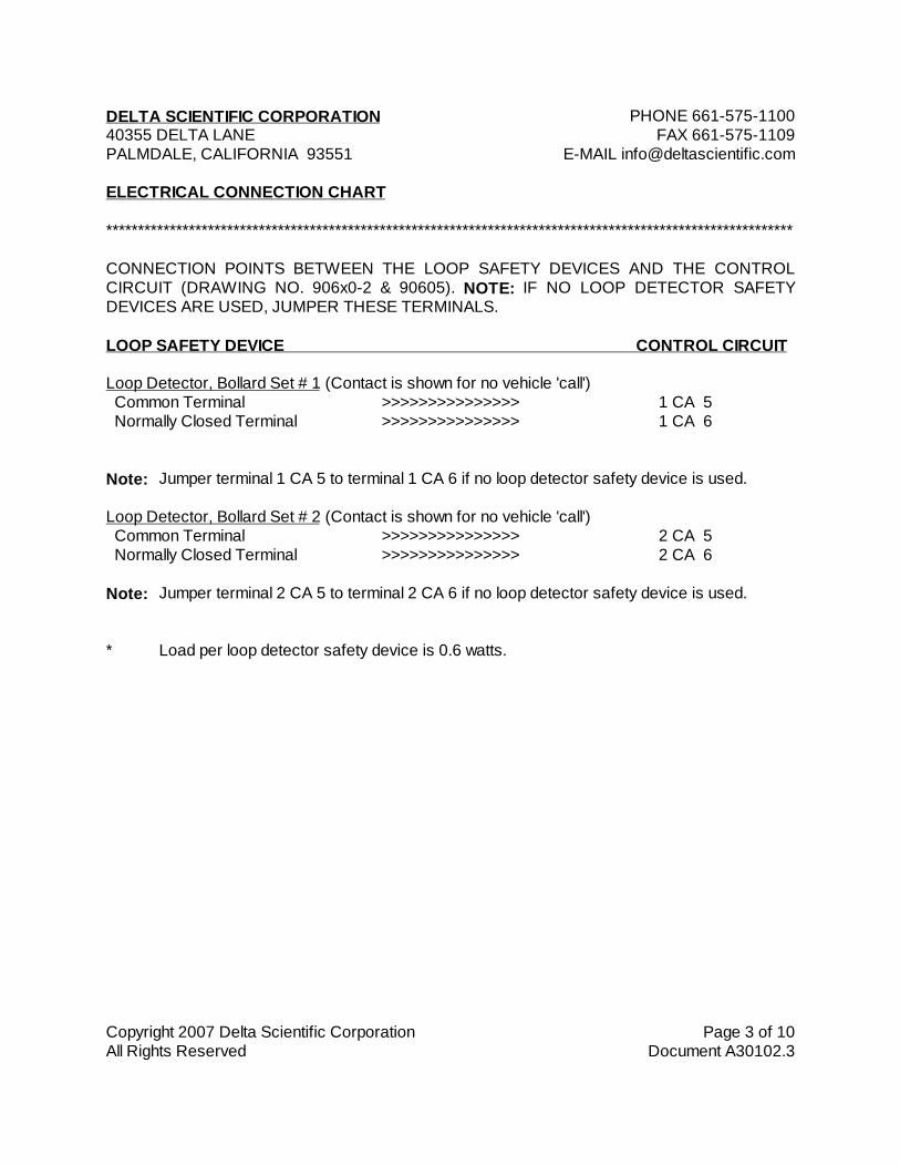
CONNECTION POINTS BETWEEN THE LOOP SAFETY DEVICES AND THE CONTROLCIRCUIT (DRAWING NO. 906x0-2 & 90605). NOTE: IF NO LOOP DETECTOR SAFETYDEVICES ARE USED, JUMPER THESE TERMINALS.
LOOP SAFETY DEVICE CONTROL CIRCUIT
Loop Detector, Bollard Set # 1 (Contact is shown for no vehicle 'call') Common Terminal >>>>>>>>>>>>>>> 1 CA 5 Normally Closed Terminal >>>>>>>>>>>>>>> 1 CA 6
Note: Jumper terminal 1 CA 5 to terminal 1 CA 6 if no loop detector safety device is used.
Loop Detector, Bollard Set # 2 (Contact is shown for no vehicle 'call') Common Terminal >>>>>>>>>>>>>>> 2 CA 5 Normally Closed Terminal >>>>>>>>>>>>>>> 2 CA 6
Note: Jumper terminal 2 CA 5 to terminal 2 CA 6 if no loop detector safety device is used.
* Load per loop detector safety device is 0.6 watts.

DELTA SCIENTIFIC CORPORATION PHONE 661-575-110040355 DELTA LANE FAX 661-575-1109PALMDALE, CALIFORNIA 93551 E-MAIL [email protected]
Copyright 2007 Delta Scientific Corporation Page 4 of 10All Rights Reserved Document A30102.3
ELECTRICAL CONNECTION CHART
************************************************************************************************************
STOP/GO SIGNAL LIGHTS
CONNECTION POINTS BETWEEN THE CONTROL CIRCUIT (DRAWING NO. 906x0-2 &90605) AND ONE OR MORE STOP/GO TRAFFIC LIGHTS.
This circuit synchronizes the stop/go lights with either of the Bollard Sets. As soon as a BollardSet starts to rise the red "stop" light comes on and stays on until the Bollard Set has been loweredand is fully down. The green "go" light comes on at this point.
STOP/GO SIGNAL LIGHTS CONTROL CIRCUIT
Signal Lights for Bollard Set # 1 Supply Voltage >>>> Note 2 >>>> 1 CB 1 Supply Voltage >>>> Note 2 >>>> 1 CB 2 Common Terminal >>>> Note 2 >>>> 1 CB 3 Signal Green Light >>>> Note 1 >>>> 1 CB 4 Signal Red Light >>>> Note 1 >>>> 1 CB 5
Signal Lights for Bollard Set # 2 Supply Voltage >>>> Note 2 >>>> 2 CB 1 Supply Voltage >>>> Note 2 >>>> 2 CB 2 Common Terminal >>>> Note 2 >>>> 2 CB 3 Signal Green Light >>>> Note 1 >>>> 2 CB 4 Signal Red Light >>>> Note 1 >>>> 2 CB 5
Note 1: These lines must be sized to handle one 40 Watts (maximum) incandescent bulboperating at the AC Control Voltage. If back to back lights are used, twice thecurrent must be handled.
Note 2: If the commons are combined, the total of all currents must be considered.

DELTA SCIENTIFIC CORPORATION PHONE 661-575-110040355 DELTA LANE FAX 661-575-1109PALMDALE, CALIFORNIA 93551 E-MAIL [email protected]
Copyright 2007 Delta Scientific Corporation Page 5 of 10All Rights Reserved Document A30102.3
ELECTRICAL CONNECTION CHART
************************************************************************************************************
STOP/GO SIGNAL GATE, MODEL AG812
ADDITIONAL CONNECTION POINTS BETWEEN THE CONTROL CIRCUIT (DRAWING NO.906x0-2 & 90605) AND THE STOP/GO SIGNAL GATE MODEL AG812.
The Stop/Go Signal Gate Model AG812 is designed to have its motion coordinated with itscompanion Bollard Set. Upon raising the Bollards, the Signal Gate will lower to provide visualindication to drivers to stop. The Signal Gate will remain in the down position until the Bollards areagain lowered to the full down position at which point the Bollards' down limit switch will cause theSignal Gate to raise.
STOP/GO SIGNAL GATE CONTROL CIRCUIT
Signal Gate for Bollard Set # 11 Terminal 12 >>>> Note 1 >>>> 1 CB 101 Terminal 14 >>>> Note 1 >>>> 1 CB 11
Signal Gate for Bollard Set # 22 Terminal 12 >>>> Note 1 >>>> 2 CB 102 Terminal 14 >>>> Note 1 >>>> 2 CB 11
Note 1: The Model AG812 Signal Gates have the local control voltage brought to terminalsL1 and L2. Signal Gate jumpers are on terminals CA 3 and CA 5 (changed fromterminals CA 4 and CA 5).

DELTA SCIENTIFIC CORPORATION PHONE 661-575-110040355 DELTA LANE FAX 661-575-1109PALMDALE, CALIFORNIA 93551 E-MAIL [email protected]
Copyright 2007 Delta Scientific Corporation Page 6 of 10All Rights Reserved Document A30102.3
ELECTRICAL CONNECTION CHART
************************************************************************************************************
CONNECTION POINTS BETWEEN THE CONTROL CIRCUIT (DRAWING NO. 906x0-2 &90605) AND THE MASTER CONTROL PANEL (DRAWING NO. 907xx).
REMOTE CONTROL PANEL CONTROL CIRCUIT
1 MA 3 (+) >>>>>>> Note 2 >>>>>>> 1 CA 3 + (HOT) Note 1 1 MA 18 (-) >>>>>>> Note 2 >>>>>>> 1 CA 18 - (NEUTRAL) Note 1 1 MA 4 (#1 Close) >>>>>>>>>>>>>>>>>>>> 1 CA 4 1 MA 8 (#1 Open) >>>>>>>>>>>>>>>>>>>> 1 CA 8 1 MA 14 (Emergency) >>>>>>> Note 2 >>>>>>> 1 CA 14 1 MA 15 (Emergency Reset) >>>>>>> Note 2 >>>>>>> 1 CA 15 1 MA 19 (#1 Clear) >>>>>>>>>>>>>>>>>>>> 1 CA 19 1 MA 20 (#1 Not Clear) >>>>>>>>>>>>>>>>>>>> 1 CA 20 2 MA 4 (#2 Close) >>>>>>>>>>>>>>>>>>>> 2 CA 4 2 MA 8 (#2 Open) >>>>>>>>>>>>>>>>>>>> 2 CA 8 2 MA 19 (#2 Clear) >>>>>>>>>>>>>>>>>>>> 2 CA 19 2 MA 20 (#2 Not Clear) >>>>>>>>>>>>>>>>>>>> 2 CA 20
Note 1: Size neutral and hot for 50 watts (maximum). All other lines are 1 watts each.
Note 2: The terminals 1 MA and 2 MA for these lines are jumpered at the factory; 1 MA 3to 2 MA 3, 1 MA 18 to 2 MA 18, etc. A jumper will be required between the circuitboards in the control circuit.

DELTA SCIENTIFIC CORPORATION PHONE 661-575-110040355 DELTA LANE FAX 661-575-1109PALMDALE, CALIFORNIA 93551 E-MAIL [email protected]
Copyright 2007 Delta Scientific Corporation Page 7 of 10All Rights Reserved Document A30102.3
ELECTRICAL CONNECTION CHART
************************************************************************************************************
CONNECTION POINTS BETWEEN THE SLAVE PANEL (DRAWING NO. 908xx) AND THEMASTER PANEL (DRAWING NO. 907xx) OR THE CONTROL CIRCUIT (DRAWING NO.906x0-2 & 90605). (See Note 1)
SLAVE REMOTE PANEL MASTER REMOTE PANEL CONTROL CIRCUIT
1 SA 4 >>>>>>>>>>>>>> 1 MA 4 >>>>>>>>>>>>> 1 CA 41 SA 8 >>>>>>>>>>>>>> 1 MA 8 >>>>>>>>>>>>> 1 CA 81 SA 14 >>>> Note 3 >>>> 1 MA 14 >>>>>>>>>>>>> 1 CA 141 SA 15 >>>> Note 3 >>>> 1 MA 15 >>>>>>>>>>>>> 1 CA 151 SA 18 >>>> Note 3 >>>> 1 MA 18 >>>>>>>>>>>>> 1 CA 181 SA 19 >>>>>>>>>>>>>> 1 MA 19 >>>>>>>>>>>>> 1 CA 191 SA 20 >>>>>>>>>>>>>> 1 MA 20 >>>>>>>>>>>>> 1 CA 201 SA 27 >>>> Note 3 >>>> 1 MA 27 Annunciator - Note 21 SA 28 >>>> Note 3 >>>> 1 MA 28 + Hot - Note 22 SA 4 >>>>>>>>>>>>>> 2 MA 4 >>>>>>>>>>>>> 2 CA 42 SA 8 >>>>>>>>>>>>>> 2 MA 8 >>>>>>>>>>>>> 2 CA 82 SA 19 >>>>>>>>>>>>>> 2 MA 19 >>>>>>>>>>>>> 2 CA 192 SA 20 >>>>>>>>>>>>>> 2 MA 20 >>>>>>>>>>>>> 2 CA 20
Note 1: The Slave can be fed from either the Master or from the Control Circuit. If theSlave is fed from the Master, then connect as shown in the two left columns above.If the Slave is fed from the Control Circuit use the left and right columns as shownabove.
Note 2: These connections must be made directly from the Slave Remote to the MasterRemote. The routing can be made through the Control Circuit on a spare terminalif this is more convenient.
Note 3: The terminals 1 SA and 2 SA for these lines can be commoned. A jumper will berequired between the circuit boards in the control circuit.
DELTA SCIENTIFIC CORPORATION PHONE 661-575-110040355 DELTA LANE FAX 661-575-1109PALMDALE, CALIFORNIA 93551 E-MAIL [email protected]
Copyright 2007 Delta Scientific Corporation Page 8 of 10All Rights Reserved Document A30102.3
ELECTRICAL CONNECTION CHART
************************************************************************************************************
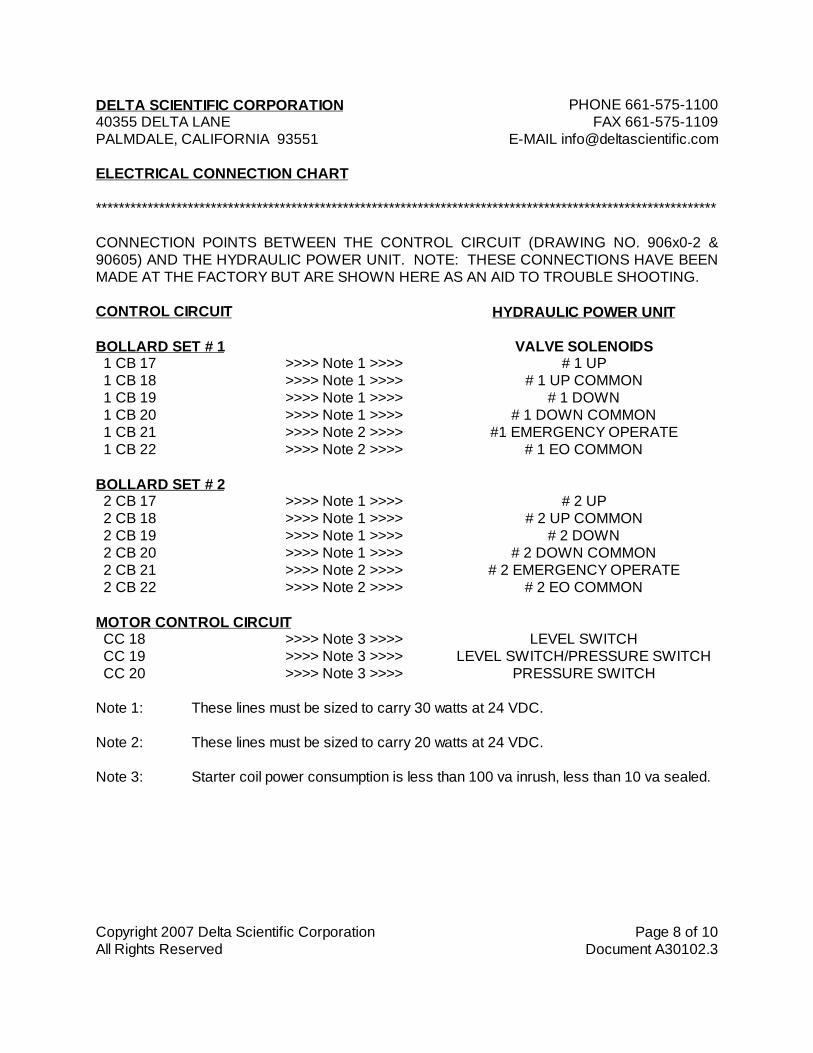
CONNECTION POINTS BETWEEN THE CONTROL CIRCUIT (DRAWING NO. 906x0-2 &90605) AND THE HYDRAULIC POWER UNIT. NOTE: THESE CONNECTIONS HAVE BEENMADE AT THE FACTORY BUT ARE SHOWN HERE AS AN AID TO TROUBLE SHOOTING.
CONTROL CIRCUIT HYDRAULIC POWER UNIT
BOLLARD SET # 1 VALVE SOLENOIDS 1 CB 17 >>>> Note 1 >>>> # 1 UP 1 CB 18 >>>> Note 1 >>>> # 1 UP COMMON 1 CB 19 >>>> Note 1 >>>> # 1 DOWN 1 CB 20 >>>> Note 1 >>>> # 1 DOWN COMMON 1 CB 21 >>>> Note 2 >>>> #1 EMERGENCY OPERATE 1 CB 22 >>>> Note 2 >>>> # 1 EO COMMON
BOLLARD SET # 2 2 CB 17 >>>> Note 1 >>>> # 2 UP 2 CB 18 >>>> Note 1 >>>> # 2 UP COMMON 2 CB 19 >>>> Note 1 >>>> # 2 DOWN 2 CB 20 >>>> Note 1 >>>> # 2 DOWN COMMON 2 CB 21 >>>> Note 2 >>>> # 2 EMERGENCY OPERATE 2 CB 22 >>>> Note 2 >>>> # 2 EO COMMON
MOTOR CONTROL CIRCUIT CC 18 >>>> Note 3 >>>> LEVEL SWITCH CC 19 >>>> Note 3 >>>> LEVEL SWITCH/PRESSURE SWITCH CC 20 >>>> Note 3 >>>> PRESSURE SWITCH
Note 1: These lines must be sized to carry 30 watts at 24 VDC.
Note 2: These lines must be sized to carry 20 watts at 24 VDC.
Note 3: Starter coil power consumption is less than 100 va inrush, less than 10 va sealed.

DELTA SCIENTIFIC CORPORATION PHONE 661-575-110040355 DELTA LANE FAX 661-575-1109PALMDALE, CALIFORNIA 93551 E-MAIL [email protected]
Copyright 2007 Delta Scientific Corporation Page 9 of 10All Rights Reserved Document A30102.3
ELECTRICAL CONNECTION CHART
************************************************************************************************************
CONTROL CIRCUIT
The Control Circuit is fed from the customer's local AC control voltage supply (either 100-120/1/50-60 or 200-240/1/50-60). Connection is to terminals CC 1(+) and CC 2(-). Supply shouldbe adequate to provide a minimum of 250 Watts of power.
The control circuit contains a power supply, which reduces the local voltage to 24 VDC for use onthe remote control panels. The feed out of the control circuit for these remotes is on terminal CA1(+) and CA 2(-). Standard power capability is 150 watts. Battery back up power supply/chargerand batteries are optionally available.
Note: Use caution when installing the field conduits and wiring to the control circuit enclosure.Shield metal chips and wire fragments from falling on to or in to components. Component failurecan be caused by careless installation.
POWER UNIT MOTORS
The motor has been ordered and supplied to the actual site voltage. Please confirm beforehookup. The motor is factory wired to an automatic starter controlled by the hydraulic power unitpressure switch, oil level switch and (optional) three phase power monitor. Thermal overloadprotection is integrally provided.
The customer should provide branch circuit protection as required by national and local code.Care should be taken in arriving at the correct wire size for the length of cable provided.
HYDRAULIC POWER UNIT WIRING
The three phase power is brought into the HPU terminal box to the line side of the door mounteddisconnect switch at L1, L2 and L3.
Verify that the motor runs in the correct direction. Units with phase monitors (three phase only)are factory set to run in the correct direction. If motor does not run, or runs in the wrong direction,reverse any two incoming wires at L1, L2 or L3; motor should now run and in the correct direction.
Power for the starter contactor coil is the same as the primary voltage of the control circuit. Coilvoltage legend plates are on the starter so that this can be confirmed. Connection points for thecoil power are 'CC 1(+)' and 'CC 2(-)'. Starter coil power consumption is less than 100 va inrush,and less than 10 va sealed.
DELTA SCIENTIFIC CORPORATION PHONE 661-575-110040355 DELTA LANE FAX 661-575-1109PALMDALE, CALIFORNIA 93551 E-MAIL [email protected]
Copyright 2007 Delta Scientific Corporation Page 10 of 10All Rights Reserved Document A30102.3
ELECTRICAL CONNECTION CHART
************************************************************************************************************
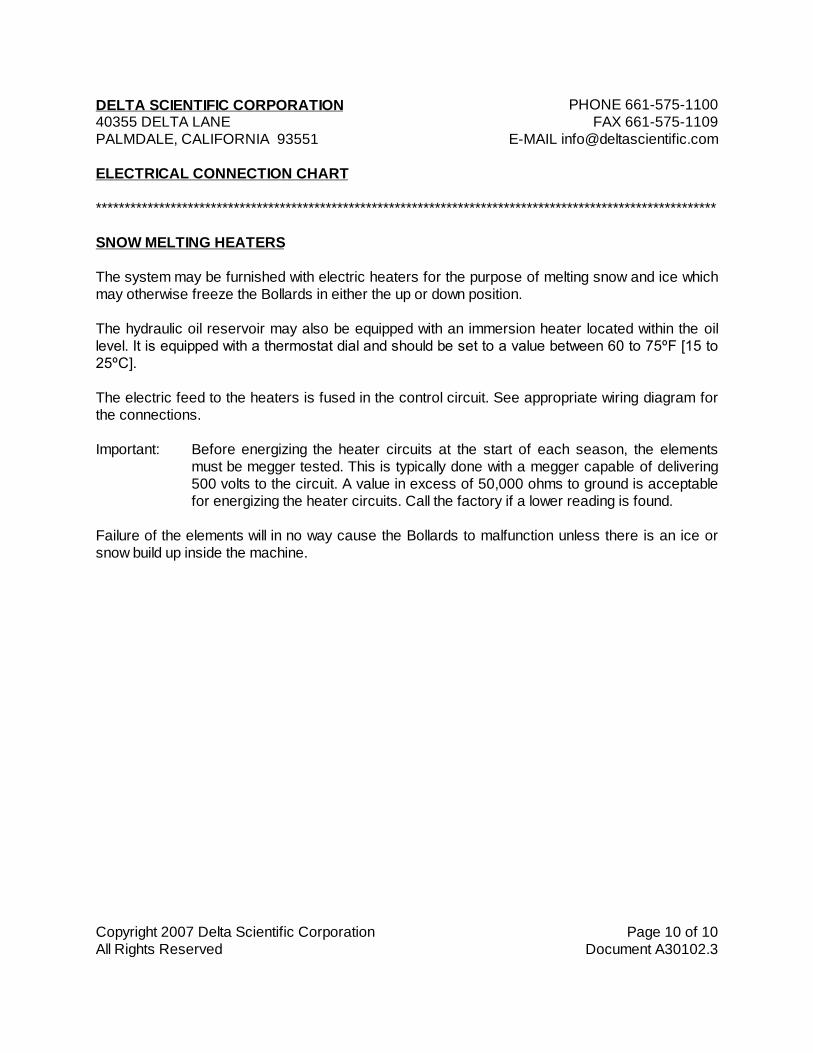
SNOW MELTING HEATERS
The system may be furnished with electric heaters for the purpose of melting snow and ice whichmay otherwise freeze the Bollards in either the up or down position.
The hydraulic oil reservoir may also be equipped with an immersion heater located within the oillevel. It is equipped with a thermostat dial and should be set to a value between 60 to 75ºF [15 to25ºC].
The electric feed to the heaters is fused in the control circuit. See appropriate wiring diagram forthe connections.
Important: Before energizing the heater circuits at the start of each season, the elementsmust be megger tested. This is typically done with a megger capable of delivering500 volts to the circuit. A value in excess of 50,000 ohms to ground is acceptablefor energizing the heater circuits. Call the factory if a lower reading is found.
Failure of the elements will in no way cause the Bollards to malfunction unless there is an ice orsnow build up inside the machine.
Copyright 2005 Delta Scientific Corporation Page 1 of 14All Rights Reserved Document A30230.1
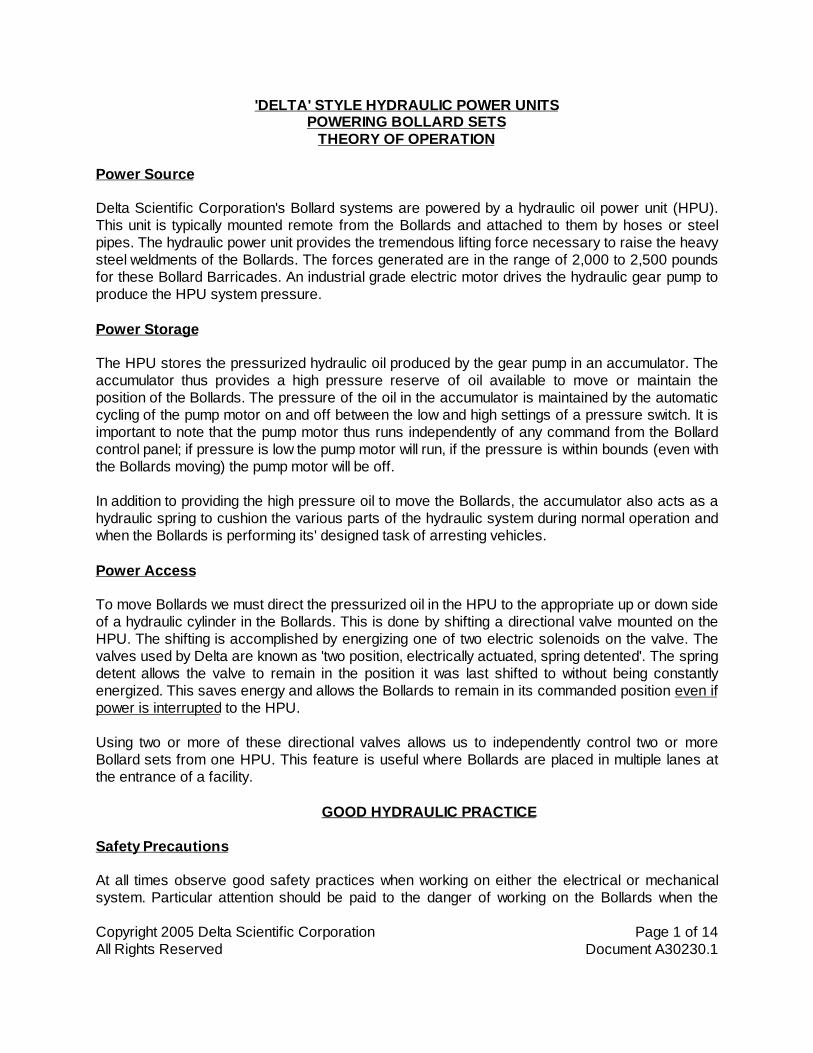
'DELTA' STYLE HYDRAULIC POWER UNITSPOWERING BOLLARD SETS
THEORY OF OPERATION
Power Source
Delta Scientific Corporation's Bollard systems are powered by a hydraulic oil power unit (HPU).This unit is typically mounted remote from the Bollards and attached to them by hoses or steelpipes. The hydraulic power unit provides the tremendous lifting force necessary to raise the heavysteel weldments of the Bollards. The forces generated are in the range of 2,000 to 2,500 poundsfor these Bollard Barricades. An industrial grade electric motor drives the hydraulic gear pump toproduce the HPU system pressure.
Power Storage
The HPU stores the pressurized hydraulic oil produced by the gear pump in an accumulator. Theaccumulator thus provides a high pressure reserve of oil available to move or maintain theposition of the Bollards. The pressure of the oil in the accumulator is maintained by the automaticcycling of the pump motor on and off between the low and high settings of a pressure switch. It isimportant to note that the pump motor thus runs independently of any command from the Bollardcontrol panel; if pressure is low the pump motor will run, if the pressure is within bounds (even withthe Bollards moving) the pump motor will be off.
In addition to providing the high pressure oil to move the Bollards, the accumulator also acts as ahydraulic spring to cushion the various parts of the hydraulic system during normal operation andwhen the Bollards is performing its' designed task of arresting vehicles.
Power Access
To move Bollards we must direct the pressurized oil in the HPU to the appropriate up or down sideof a hydraulic cylinder in the Bollards. This is done by shifting a directional valve mounted on theHPU. The shifting is accomplished by energizing one of two electric solenoids on the valve. Thevalves used by Delta are known as 'two position, electrically actuated, spring detented'. The springdetent allows the valve to remain in the position it was last shifted to without being constantlyenergized. This saves energy and allows the Bollards to remain in its commanded position even ifpower is interrupted to the HPU.
Using two or more of these directional valves allows us to independently control two or moreBollard sets from one HPU. This feature is useful where Bollards are placed in multiple lanes atthe entrance of a facility.
GOOD HYDRAULIC PRACTICE
Safety Precautions
At all times observe good safety practices when working on either the electrical or mechanicalsystem. Particular attention should be paid to the danger of working on the Bollards when the

Copyright 2005 Delta Scientific Corporation Page 2 of 14All Rights Reserved Document A30230.1
power is on. The Bollards are powerful hydraulic presses that can easily crush anything in theirway. Keep hands free of the mechanism when the power is on or the HPU is up to pressure. Turnoff the electric power and bleed the hydraulic pressure down to zero before working on any part ofthe system. Traffic should be controlled around the Bollards during any work so that vehicularaccidents do not occur if the Bollards should happen to rise. After work is complete, do not allowtraffic over the Bollards until all control and safety functions have been verified to be properlyworking.
Cleanliness
To maintain system efficiency and reliability great care must be taken to prevent any form of dirt,sand or grit from entering the hydraulic system. Only new, clean filtered hydraulic oil should beused for charging the unit. Unless specifically ordered as filtered, new oil should be pumpedthrough a 25 micron filter when charging. See Commercial Hydraulic Oil InterchangeabilityChart for our recommended oils. The tests conducted at the factory on the system have beendone with the HPU charged with Shell 'Tellus' 46. This grade is for moderate temperatures and isavailable in most of the worlds leading cities.
Hydraulic oil is subject to degradation and contamination with age, so follow the recommendationsin the Maintenance section of this manual.
Location
The hydraulic power unit should be mounted indoors in a clean, dry location away from excessiveheat or cold. As an alternate the unit can be mounted outdoors if provided with a suitable coverdesigned for the area to exclude moisture or dust as appropriate. While HPU's have beenmounted below grade in concrete pits, we do not recommend this as drainage becomes extremelyimportant. A drain backup can cause the power unit to go under water with severe damageresulting. Also, the water condensation found in most pits is detrimental to the HPU components.
It is important that the hydraulic power unit be mounted at approximately the same or higherelevation as the Bollards. If the HPU is mounted lower than the Bollards, the oil in the lines mayrepeatedly drain back to tank and make the Bollard's motion erratic. The power unit can be atelevation greater than the Bollards if it is understood that breaking a line at the Bollards will causeoil to flow in that direction.
System Component Description
The hydraulic power unit (HPU) is assembled on a steel framework which supports the hydraulicoil reservoir and major components. Provision is made to permit bolting or lagging of the frame toa suitable foundation. See the appropriate General Arrangement drawing for hole and interfacedimensions.
The power unit has been pre-tested for function and leaks at the factory prior to shipment.Preparation for shipment calls for the draining of the test oil, however, approximately one inch [25mm] will remain in the tank after draining.
Copyright 2005 Delta Scientific Corporation Page 3 of 14All Rights Reserved Document A30230.1
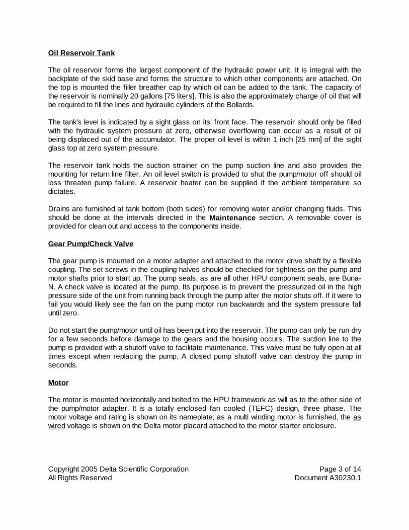
Oil Reservoir Tank
The oil reservoir forms the largest component of the hydraulic power unit. It is integral with thebackplate of the skid base and forms the structure to which other components are attached. Onthe top is mounted the filler breather cap by which oil can be added to the tank. The capacity ofthe reservoir is nominally 20 gallons [75 liters]. This is also the approximately charge of oil that willbe required to fill the lines and hydraulic cylinders of the Bollards.
The tank's level is indicated by a sight glass on its' front face. The reservoir should only be filledwith the hydraulic system pressure at zero, otherwise overflowing can occur as a result of oilbeing displaced out of the accumulator. The proper oil level is within 1 inch [25 mm] of the sightglass top at zero system pressure.
The reservoir tank holds the suction strainer on the pump suction line and also provides themounting for return line filter. An oil level switch is provided to shut the pump/motor off should oilloss threaten pump failure. A reservoir heater can be supplied if the ambient temperature sodictates.
Drains are furnished at tank bottom (both sides) for removing water and/or changing fluids. Thisshould be done at the intervals directed in the Maintenance section. A removable cover isprovided for clean out and access to the components inside.
Gear Pump/Check Valve
The gear pump is mounted on a motor adapter and attached to the motor drive shaft by a flexiblecoupling. The set screws in the coupling halves should be checked for tightness on the pump andmotor shafts prior to start up. The pump seals, as are all other HPU component seals, are Buna-N. A check valve is located at the pump. Its purpose is to prevent the pressurized oil in the highpressure side of the unit from running back through the pump after the motor shuts off. If it were tofail you would likely see the fan on the pump motor run backwards and the system pressure falluntil zero.
Do not start the pump/motor until oil has been put into the reservoir. The pump can only be run dryfor a few seconds before damage to the gears and the housing occurs. The suction line to thepump is provided with a shutoff valve to facilitate maintenance. This valve must be fully open at alltimes except when replacing the pump. A closed pump shutoff valve can destroy the pump inseconds.
Motor
The motor is mounted horizontally and bolted to the HPU framework as will as to the other side ofthe pump/motor adapter. It is a totally enclosed fan cooled (TEFC) design, three phase. Themotor voltage and rating is shown on its nameplate; as a multi winding motor is furnished, the aswired voltage is shown on the Delta motor placard attached to the motor starter enclosure.

Copyright 2005 Delta Scientific Corporation Page 4 of 14All Rights Reserved Document A30230.1
Motor/pump direction of rotation is critical. A direction arrow decal is provided. The motor mustrun in this direction when site power is brought to the HPU skid. If the motor does not run in theproper direction on startup, reverse any two incoming wires to the control circuit disconnectswitch.
Phase Monitor (Optional)
An optional phase (voltage) monitor may be supplied to protect the motor from improper phasing,phase loss, or low voltage. The monitor will drop out the motor starter circuit if the three phasepower is phased wrong or if the voltage is too low. The unit has been proper phased at thefactory. If the motor does not run on initial startup, reverse any two incoming wires to the controlcircuit disconnect switch. The motor should now run and in the correct direction.
Magnetic Motor Starter/Overload
Site voltage is fed to the line side of the motor starter/thermal overload. See voltage placardattached to the starter enclosure for the as wired voltage and motor starter circuit drawingnumber. The feed to the HPU should be controlled from an appropriately sized circuitbreaker/disconnect switch and the wires sized properly to prevent excessive voltage drop fromthe disconnect to the HPU skid. Motors should not be allowed to run at voltages exceeding +/- 10percent of their ratings. This could lead to tripping of the thermal overloads or substantial damageto the motor and control circuit components.
The thermal overload is calibrated for the anticipated full load amperage of the motor at runvoltage, this setting should be confirmed before start up (the amperage dial of the overload shouldbe set for the full load amps labeled on the motor nameplate). The overload should be in theMANUAL position, automatic reset could cause equipment failure if a fault is not corrected in atimely manner.
A voltage/phase monitor may optionally be furnished. In addition to protecting the pump againstimproper rotation, it will shutdown the motor starter circuit if phase loss/reversal or low voltage isdetected.
Accumulator
The accumulator is a large cylindrical pressure vessel that provides the high pressure reserve ofoil used to move the Bollards and keep them in position. In addition, the oil stored in theaccumulator is available to move the Bollards even if the pump/motor should be inoperable. Theamount of oil directed out to the Bollards is not limited by the displacement rate of the hydraulicgear pump but by the oil stored in the accumulator.
An accumulator is divided into two sides by a piston (piston accumulator). On the top side, theaccumulator contains dry nitrogen gas pre-pressurized (precharged) at the factory at a leveldetermined by the type of Bollards ordered. The fittings and seals on the nitrogen fill connectionshould be kept tight to prevent loss of this precharge. A special tool is available from DeltaScientific to check the precharge pressure and facilitate recharging if that should becomenecessary. Precharge should be checked every six months (see Maintenance section of this

Copyright 2005 Delta Scientific Corporation Page 5 of 14All Rights Reserved Document A30230.1
manual). The pump/motor should not be run if there is no precharge, damage to the accumulatorcould result. Only dry nitrogen should be used for precharge, air or other gases could cause theaccumulator vessel to explode. Precharge should only be done at zero hydraulic pressure or anincorrect precharge pressure will result.
The other side of the accumulator contains the system hydraulic oil. At zero hydraulic oil pressurethere is little or no oil in the accumulator, the piston is down hard on the oil outlet. As thepump/motor runs, oil accumulates on the oil side at the pressure indicated by the system pressuregage (oil side). This pressure gage will read the precharge indirectly by jumping to the prechargevalue on motor startup then slowly running up to the shut off pressure. It is important to note that atshut off, only a portion of the accumulator contains oil, the piston has been pushed back tocompress the nitrogen gas which is now also at the shutoff pressure. It is the compressed gasthat provides the 'spring' to move oil out of the accumulator and to the cylinders of the Bollards.
When performing accumulator maintenance it is necessary to bring the oil side pressure to zero.Large oil loss can occur if fittings are tampered with while under pressure.
Pressure Switch
The pressure at which the oil side is maintained is determined by a pressure switch mounted onthe high pressure (pump or accumulator) side of the system. The switch is factory set for theproper shutoff pressure of 1900 psig [131 bar] and has a 500 psig [34 bar] 'dead-band'. Thismeans that the pressure will fall approximately 500 psi [34 bar] after shutoff (about 1400 psig [97bar]) before the switch closes to restart the pump motor. These settings should be indicated onthe motor starter drawing and noted in the pressure log in the Maintenance section. The electricside of the switch is terminated on a terminal strip in the motor starter enclosure.
Pressure Gage
A pressure gage is provided to indicate the hydraulic oil pressure of the system. It does notindicate the accumulator precharge except as noted in the Accumulator paragraph of thissection. The gage is liquid filled with glycol to eliminate needle bounce and a vent is thus providedto allow the case to breath, preventing case blow out. Upon receipt, remove vent seal plug/label.
This gage must read zero when working on the HPU pressure lines and fittings or large oil losscan occur. A gentle tapping on the gage glass will provide the most accurate readings.
Pressure Relief Valve
A pressure relief valve is provided should the high pressure switch fail to shut off the pump motor.The relief valve is typically set at 200 to 250 psig higher than the high-pressure switch. When thepressure relief valve opens, oil is allowed to circulate from the pressure side of the system to thetank/motor suction. The motor horse power is thus being turned to heat across this valve whichcould cause component damage if allowed to operate uncorrected. The operators or guardsshould thus report to the person in charge of Bollards maintenance if they note the HPUconstantly running.

Copyright 2005 Delta Scientific Corporation Page 6 of 14All Rights Reserved Document A30230.1
An open pressure relief valve will cause a hissing sound and if the motor is not running, a fallingpressure gage would be noted. See the Mechanical Trouble Shooting section if the relief valvedoes not reseat on pressure reduction.
The pressure relief valve should in no case be set higher than 1.1 times the pressure rating of theminimum rated component in the Bollards system. Please note that most components aredesigned with a 4 to 1 safety factor, thus the burst pressure of a 2500 psig rated hose would be10,000 psig.
Low Level Switch
As noted above, an oil reservoir low level switch is provided to shut down the pump/motor if thereservoir level drops to the point where the suction of the pump could become uncovered. Thegear pump can only run dry for a few seconds before severe wear occurs on the gears and its'housing. Causes of low level are slow system leaks and catastrophic failure of the pressure linesor hoses.
Oil Filter
A return filter element may be furnished to filter the oil as it is being returned to the oil reservoir.The oil filter housing is only rated at 150 psig [10 bar] or less as the oil in the return line has onlyto overcome the pressure drop through the filter itself. If the filter should become clogged with dirtfrom the system a bypass check valve inside the filter will open and allow the dirty oil to circulateback to the reservoir. For this reason regular filter maintenance is a must. See the Maintenancesection for details.
Larger sets of Bollards may be equipped with a pressure type filter that filters the oil immediatelyafter the hydraulic pump. Since these filters see the full system pressure of 1900 psig [131 bar],they are equipped with heavy duty steel housings. Again, the comment about regular filtermaintenance applies.
Directional Control Valve
A solenoid actuated directional control valve is provided to direct the high pressure oil to the up ordown side of the Bollards' cylinders. One or more (depending on the number of Bollard sets to becontrolled) are mounted on an aluminum manifold bolted to the back plate on the oil reservoir.When the 'up' side is energized, the valve connects the high pressure (P) side of the manifold tothe (B) output port of the manifold. The tank return line (T) is simultaneously connected to the (A)output port. When the 'down' side is energized, the manifold (P) side is connected to the (A) portand the (T) side is connected to the (B) port.
The directional valve is equipped with pin extensions mounted on the solenoid ends so that thevalve spool can be manually shifted by inserting a pin with a diameter of approximately 0.125 inch[3 mm]. As described above in the Power Access paragraph, the valve has spring detents sothat it remains in the last commanded position until moved by the electric solenoids or the overridepins. See the applicable 'Hydraulic Valve Connection' drawing.

Copyright 2005 Delta Scientific Corporation Page 7 of 14All Rights Reserved Document A30230.1
The spool of the valve is designed to provide 'closed center ports' so that if the valve malfunctionsand does not fully shift, the ports will be closed to one another. Note that these valves requireclearance between the spool and the valve body to properly function, thus some leakage frompressure to tank is to be expected. Excessive valve wear will eventually cause the pump/motor tocycle on and off several times per minute even when the Bollards are not moving. Replacement orrebuilding of the affected valve will then be required.
The convention used on all Delta Bollards systems regarding the directional control solenoidvalves is as follows:
Directional Control Solenoid Numbering: Valve one (station one) is the bottom most valve on themanifold with the station number increasing to the top of the valve stack.
Color Codes:Side/Solenoid Wire Color Function
Left/'B' Black UPRight/'A' Red DOWN
--- White COMMON--- Green GROUND
The valve is held to the manifold with high tensile cap screws. Buna-N O-rings are used to sealthe valve port face to the manifold. It is imperative that the mating faces be clean and all 'O' ringsin place and lightly lubricated with hydraulic oil before evenly torquing the cap screws.
Valve mounting screw torque:
NFPA DO1/ISO 03 40 to 50 in-lbs. [5 to 6 N-M]
Speed Control Valves
Each directional valve station has speed control valves to control the normal up and down speedof the Bollards. They are located in the B line before the B hose. These Bollards require only asingle needle valve which will adequately control both the up and down speeds.
Clockwise turning of the adjustment knob is slower (valve closing), faster speed is gained byopening the valve (counter-clockwise). The valve should be locked with the set screw providedafter adjustment.
Emergency Fast Operate (EFO) Valve (Optional)
Some systems are equipped with optional emergency fast operate (EFO) bypass valves. Thesesolenoid valves when energized directly connect the high pressure (P) side of the HPU to the upside of the Bollard cylinders. This bypasses the normal Bollard speed control valves and allowsthe Bollards to rise at the maximum possible speed. The valves are 'cartridge' style and aremounted in an aluminum body plumbed from the (P) side of the system to the (B) output portimmediately before the (B) hoses.

Copyright 2005 Delta Scientific Corporation Page 8 of 14All Rights Reserved Document A30230.1
Should it become necessary to replace an EFO valve cartridge, the following mounting torquesapply:
Solenoid Coil Retaining Nut 60 in-lbs. [7 N-M]Cartridge to Body 420 in-lbs. [48 N-M]
Auxiliary Emergency Fast Operate Valve (Optional)
Some systems are equipped with an optional additional accumulator separated from the primaryaccumulator by an auxiliary emergency fast operate valve. This solenoid valve allows oil to becharged into the auxiliary accumulator and held in reserve until the 'emergency fast operate valve'is actuated. The valve then releases high pressure oil to the P side of the system, even if theprimary accumulator has been exhausted. The valve is very similar to the normal EFO valveexcept that it is equipped with a manual override pin so that the auxiliary accumulator can be bleeddown prior to performing maintenance.
Should it become necessary to replace an auxiliary EFO valve cartridge, the following mountingtorque applies:
Series 14 - Solenoid Coil Retaining Nut 30 in-lbs. [15 N-M]Cartridge to Body 190 in-lbs. [22 N-M]
Series 21 - Solenoid Coil Retaining Nut 30 in-lbs. [15 N-M]Cartridge to Body 475 in-lbs. [55 N-M]
Hand Pump
In the event power should be lost to the pump/motor, the Bollards can be raised by working amanual hand pump which is mounted adjacent to the pump/motor on the skid base. The handpump has its' own internal check valve so no fluid is lost through the hand pump back to tankduring normal motor driven pump operation. The suction line to the hand pump is located near thereservoir bottom. In use, the hand pump supplies oil to the pressure (P) side of the hydraulicsystem. The pump can be operated at anytime.
To raise a Bollard set with the hand pump when electricity is out:
1) Check sight gage for proper fluid level, add oil as necessary.
2) Make sure accumulator bypass (bleed down) valve is closed.
3) Shift directional valve spool of Bollard set from left (Up) side.
4) Start pumping (each stroke should be productive). Pump until the Bollards are fully up.
5) Continue pumping for 10 to 20 strokes after the Bollards are up. This will add some oil tothe accumulator to provide for some internal leakage before the Bollards would start todrift down from low pressure.
Copyright 2005 Delta Scientific Corporation Page 9 of 14All Rights Reserved Document A30230.1
System Bleed Down Valve
Prior to performing any work on the hydraulic power unit or Bollards it is necessary to bleed downthe pressure stored in the accumulator(s). Note: It is especially necessary to bleed the power unitdown to zero hydraulic pressure before topping off the reservoir with fresh oil; large oil spillagecan occur if the unit is not at zero pressure when the reservoir is topped off! This isaccomplished with the accumulator bypass or bleed down needle valve located between the highpressure side of the system and the reservoir tank. (Typically this valve is mounted behind thehand pump in a line tied to the hand pump suction line.)
To bleed down the system:
1) Turn off electrical power to the pump/motor.
2) If system is equipped with the optional auxiliary emergency fast operate system, releasethe auxiliary EFO valve override pin by twisting and pulling to the out position.
3) Release set screw. Crack open the bypass needle valve slightly until hissing sound isheard. Continue to open slowly until pressure on gage reads zero.
4) For added safety, leave valve open while performing maintenance.
To resume operation, close the bypass valve snugly and lock with the set screw. Turn on systempower
Hydraulic Interconnect Lines
Delta Scientific uses one of two systems to connect the hydraulic power unit to the Bollards.Applicable to both systems is a need to run the lines in the most direct route as possible, keepingbends to a minimum. Long runs will slow the Bollards rise time and must be compensated byincreasing the flow diameter. In general, all runs over 50 feet [15 M] should first be cleared withthe factory, especially if minimum emergency fast rise times are critical to the installation.
The hydraulic power unit should be mounted at approximately the same or higher elevation as theBollards. Other wise, the oil in the lines may repeatedly drain back to tank and make the Bollardsmotion erratic.
Cleanliness is another important requirement for the hydraulic interconnect lines. Dirt or metalchips will find their way into the tight clearances of the components, scoring shafts and spools andwearing seals. Lack of cleanliness will shorten the service life of the system.
Flexible Hydraulic Hose
This system conveys the hydraulic oil from the HPU to the Bollards through flexible hoses which inturn are run through a larger conduit, generally a 3 inch [75 mm] PVC tube per hose pair. ThePVC conduit should be run to the Bollards in as direct a line as possible, all bends being a radiusof at least 6 diameters of the conduit. The burial depth of the conduit should be deeper than the

Copyright 2005 Delta Scientific Corporation Page 10 of 14All Rights Reserved Document A30230.1
maximum permafrost level in areas subject to freeze. This will prevent excessive pressure dropsin the hoses due to high viscosity from the cold. As the hose length changes under pressure,always provide some slack in the hose to allow for shrinkage or expansion.
All joints in the conduit system should be smooth and free from sharp edges and burrs to preventscoring the hose outer sheathing during pulling and Bollards operation. A hose under pressure isvery rigid and tends to bounce when the directional valves are shifted. Sharp edges will quicklycause a hose failure. Where the hose can not be clamped or fixed away from abrasive surfaces,a steel or plastic protective coil or sleeve should be placed over the hose.
Insulate the hose with a heat resistant boot, fire-sleeve or a metal baffle if the hose run passesnear an exhaust manifold or other heat source.
Hoses received from the factory have caps on each end and are free from dirt and othercontamination. Do not remove caps until hoses are pulled through the conduit and are ready fortermination. If caps are not present, re-clean the hoses by blowing out with clean compressed air.As an alternate, hose assemblies may be rinsed out with clean mineral spirits, being sure to flowthe mineral spirits through from top to bottom without forming any low points which will tend tocollect debris.
Before attempting to pull hoses through the conduit first inspect them. Lay the hose out straightand check that the lay-line of the assembly is not twisted. (Hoses pulled with a twist in them willtend to straighten, causing fitting nuts to loosen.) Check for scoring, cracks, bulging, kinks and dirtin the outer sheath. Check for proper gap between nut and socket or hex and socket; nuts shouldswivel freely. Be sure hose is capped securely.
If the hose must be stored for a prolonged period prior to installation it should be kept in a dark,dry atmosphere away from electrical equipment. The temperature should not exceed 90ºF [32ºC].Storage in straight lengths is preferred. While stored, the hose should be wrapped as necessarywith burlap or other suitable material to prevent damage.
Hoses should be inspected regularly when in operation, especially where the hose exits theconduit at the power unit and the Bollards. Worn or damaged hose assemblies should be replacedimmediately.
Note: Hoses supplied by Delta Scientific are generally supplied in lengths of 50 feet [15 M]. Thisis adequate for the majority of installations, however, there is generally some left over length. Coilthe hose neatly in a circle approximately 20 inches [0.5 M] in diameter at the HPU. Secure the coilwith loosely fitting cable ties or similar tying system. Do not allow the hose to rest on the ground oracross sharp corners of equipment. If the hoses are too short, extension pieces of the correctlength can be ordered. As an alternate, hoses can be held back from your shipment and made toexact requirements when the length is determined if desired. Please make arrangements at thetime of order if possible.
Special field assembly type fittings may be supplied to allow the factory length hoses to be cut andre-terminated to the exact length in the field without the use of special tools.
Copyright 2005 Delta Scientific Corporation Page 11 of 14All Rights Reserved Document A30230.1
Steel Pipe Interconnect System
As an alternate to the flexible hose system, steel pipe may be used for the run from the HPU tothe Bollards. The same comments above about short, direct runs to the Bollards apply. Typicallythe pipe run is made up above grade and dropped into a trench for direct burial (below frost level ifapplicable). If local conditions dictate, the outer portion of the pipe and fittings can be corrosionprotected by coating or tape wrapping if desired. Short lengths of hose, typically 3 feet [1 M] long,can be supplied to attach the HPU and Bollards to the pipe system. Or the piping can be plumbeddirectly to the fittings on HPU or Bollards (for this a union will be required).
The pipe used should be ASTM A-106B seamless (carbon steel) as a minimum. Care should betaken when selecting wall thickness vs. pipe diameter for the system design pressure (Delta canbe consulted for proper line sizing, strength calculations and material selection).
Fittings for the pipe run should be forged steel, ASTM A-105 or equal. Malleable iron is notacceptable. All pipe and fittings are to be furnished black, i.e., no galvanizing is permitted; thegalvanize can flake off and block or damage hydraulic components.
If desired, stainless steel pipe and fittings can be used, however, do not mix stainless steel pipewith carbon steel fittings or vis-a-vis severe corrosion of the carbon steel components couldresult. Copper and copper bearing alloys are generally unsuitable for hydraulic oil systems andshould be avoided when possible.
Interconnect Convention
So that the Bollards rises when the 'Raise' button is pressed it is necessary to coordinate theinterconnect lines with the proper HPU and Bollards connections. The following convention hasbeen established by Delta:
Color Tab HPU Port Bollards Cylinder FunctionRed 'B' Cap (Bottom) End UP
Yellow 'A' Rod (Top) End DOWN
Fittings
A variety of fittings are used on a Delta Bollards system; an understanding of how each styleseals is important so that leak free operation can be maintained.
Pipe threads are of American National Taper Pipe Thread pattern. As the name implies they sealwhen the threads pull the tapers together to form a tight joint. These threaded fittings are the onlystyle used by Delta on which Teflon tape or pipe dope may be used. Great care should be takenthat pieces of tape or liquid sealant do not end up in the part being sealed as they will eventuallyfind their way into valve seats or other critical parts. Start wrapping the tape one or two threadsback from the front of the male fitting and only one or two times around is sufficient. More thantwice around is detrimental to a tight joint. Fittings should be brought up snug but not too tight orthe female part can be distorted. If orientation of the part is critical, stop on your mark as the partis getting snug instead of trying to force the fitting another complete turn.

Copyright 2005 Delta Scientific Corporation Page 12 of 14All Rights Reserved Document A30230.1
SAE (Society of Automotive Engineers) straight threads are used on several fittings where theconnection orientation is critical. The male fitting is oriented and a locking nut with washer and O-ring is tightened against the female part. Again, do not over tighten or distortion can occur.The remaining fittings are SAE 37 degree flare fittings. These have a male nipple to which acompatible female hose or tube/nut can be attached. Most plumbing on the HPU is done with steelhydraulic tubing held to the SAE 37 degree male flare nipple with a ferrule and nut. The tube is notflared but cut square and deburred. The sealing pressure comes from the nut forcing the ferruledown onto the tube. These fittings can be broken and remade if necessary. Again snug ispreferred to overtightening.
Most hoses supplied by Delta are terminated with SAE 37 degree female swivel ends. As the nutswivels on the hose, unions are not necessary. These screw directly onto a companion SAE 37degree male nipple. To avoid confusion as to a fitting size, use the following table should orderingbe necessary:
Hose I.D. Steel Tube ODThread
Dimensions1/8" 1/8" 5/16-241/4" 1/4" 7/16-203/8" 3/8" 9/16-181/2" 1/2" 3/4-163/4" 3/4" 1-1/16-121" 1" 1-5/16-12
Note: To repeat, do not use Teflon tape or pipe dope on any straight thread fitting. Only taper pipethreads are to be so sealed.
Cylinders
The Bollards are moved by double acting hydraulic cylinders. These are specified by the borediameter and length of stroke, such as 1.25" by 30". When the Bollards are commanded to rise,oil is forced into the bottom or 'cap' end of the cylinders, extending the cylinder rods out of thecylinder bodies. The rod end of the cylinder terminates in a clevis and the clevis pin pushesagainst the Bollard to move it in the up position. When lowering, the cylinder rod retracts into thecylinder body as the oil flows out of the cap end while pressurized oil flows into the rod side. Thecylinders are pre-plumbed to 'headers' at the Delta factory. The headers terminate in the Bollard'saccess area where the customer connects the Bollards to whatever interconnect system isselected. The connection fittings are color coded as noted above in the InterconnectionConvention paragraph.
Hydraulic Oil
The hydraulic oil selected for the Bollards system is one of the most critical decisions to be madeon your installation. The properties of the oil will affect the as new performance of the Bollards aswill as the performance in years to come. Delta recommends the use of high grade, inhibitedpetroleum hydraulic oils for use in its' systems. These oils inhibit or prevent rust, oxidation,foaming and wear. They are readily available just about everywhere in the world.

Copyright 2005 Delta Scientific Corporation Page 13 of 14All Rights Reserved Document A30230.1
A viscosity compatible to the expected ambient temperature of the job site should be used. Aheavy oil used in snow conditions will tend to slow the Bollards response time down, while lightgrade oils in desert conditions may not provide lubricity necessary to prevent component wear.Most brands of oils are manufactured in different grades for this purpose.
If required, the new fire-resistant or environmentally friendly fluids can be selected, please consultyour fluid dealer for correct selection.
Automatic transmission fluid can be used and is compatible with the seal material used in all thesystem components; however, it is generally more expensive than the specially formulatedgeneral purpose hydraulic oils. Under no circumstances should brake fluid be used. It is notcompatible with the seals and will swill and degrade them.
Note: The unit as received from the factory has been tested with Shell Oil Company 'Tellus' 46.Although the unit has been drained after test approximately 1 inch [25 mm] of fluid remains in thereservoir bottom. The hydraulic oils in the following table should be compatible with this fluid.
Biodegradable Oils
Environmentally friendly oils are also acceptable for use in these systems. These fluids aregenerally based on naturally occurring vegetable oils and are biodegradable by naturally occurringorganisms when spilled or leaked in relatively small quantities. Larger spills will still need to behandled similarly to currently accepted methods for conventional mineral oil spills.
Contamination of these oils by other fluids may change the biodegradability, toxicity, or otherperformance characteristics. Systems should be cleaned as thoroughly as possible beforeintroducing a biodegradable fluid.
Delta has reviewed the data on biodegradable oils manufactured by both Mobil and Texaco.These are summarized below. Other manufacturers' products are acceptable if equal to theperformance of these oils or the standard mineral oils listed in the following pages. Consult yourlocal fluid dealer for his recommendation.
Mobil Oil Corporation Texaco Lubricants Company
Light EAL 224H Code 1607 Biostar Hydraulic 32Medium EAL 224H Code 1616 Biostar Hydraulic 46
Copyright 2005 Delta Scientific Corporation Page 14 of 14All Rights Reserved Document A30230.1
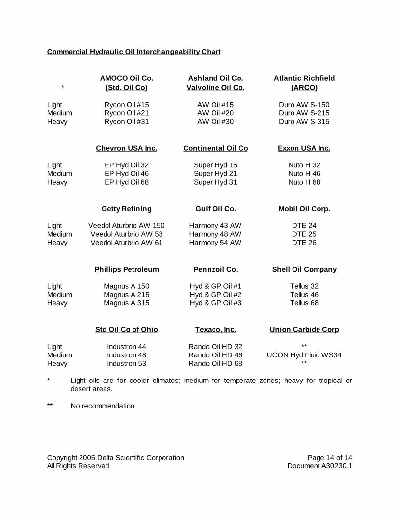
Commercial Hydraulic Oil Interchangeability Chart
AMOCO Oil Co. Ashland Oil Co. Atlantic Richfield* (Std. Oil Co) Valvoline Oil Co. (ARCO)
Light Rycon Oil #15 AW Oil #15 Duro AW S-150Medium Rycon Oil #21 AW Oil #20 Duro AW S-215Heavy Rycon Oil #31 AW Oil #30 Duro AW S-315
Chevron USA Inc. Continental Oil Co Exxon USA Inc.
Light EP Hyd Oil 32 Super Hyd 15 Nuto H 32Medium EP Hyd Oil 46 Super Hyd 21 Nuto H 46Heavy EP Hyd Oil 68 Super Hyd 31 Nuto H 68
Getty Refining Gulf Oil Co. Mobil Oil Corp.
Light Veedol Aturbrio AW 150 Harmony 43 AW DTE 24Medium Veedol Aturbrio AW 58 Harmony 48 AW DTE 25Heavy Veedol Aturbrio AW 61 Harmony 54 AW DTE 26
Phillips Petroleum Pennzoil Co. Shell Oil Company
Light Magnus A 150 Hyd & GP Oil #1 Tellus 32Medium Magnus A 215 Hyd & GP Oil #2 Tellus 46Heavy Magnus A 315 Hyd & GP Oil #3 Tellus 68
Std Oil Co of Ohio Texaco, Inc. Union Carbide Corp
Light Industron 44 Rando Oil HD 32 **Medium Industron 48 Rando Oil HD 46 UCON Hyd Fluid WS34Heavy Industron 53 Rando Oil HD 68 **
* Light oils are for cooler climates; medium for temperate zones; heavy for tropical ordesert areas.
** No recommendation

Copyright 2004 Delta Scientific Corporation Page 1 of 7All Rights Reserved Document A30330
START UP INSTRUCTIONSBOLLARDS WITH DELTA PUMPS
Safety Precautions
At all times observe good safety practices when working on either the electrical or mechanicalsystem. Particular attention should be paid to the danger of working on the Bollards when thepower is on. Bollards are powerful hydraulic presses that can easily crush anything in their way.Keep hands free of the mechanism when the power is on or the HPU is up to pressure. Turn offthe electric power and bleed the hydraulic pressure down to zero before working on any part ofthe system. Traffic should be controlled around the Bollards during any work so that vehicularaccidents do not occur if the Bollards should happen to rise. After work is complete, do not allowtraffic over the Bollards until all control and safety functions have been verified to be properlyworking.
YOUR SPECIAL ATTENTION IS CALLED TO THE FOLLOWING:
Special Safety Considerations
Delta Bollard Systems are designed to deter, and as necessary stop unauthorized vehicle trafficby inserting a nearly immovable obstacle in a roadway. During normal servicing, maintenance andtesting work, every effort must be made to protect pedestrian and vehicle traffic from enteringtraffic lanes where work is underway.
During work on either the Bollard(s), the control circuit, control logic, power unit, power feed or thecontrol panel(s); traffic across or near the Bollard(s) should either be stopped or directed into asafe passage.
Prior to starting, restarting or restoring power to a Bollard system all remote input devices such asradio links, card readers, remote control panels, etc. should be checked to insure that they areproperly set or are inactive. This is important to insure that a signal directing the Bollard to changestatus is not unexpectedly received at the time when the power is restored.
When a Bollard is powered up, whether at start-up, following a power outage or following thecompletion of service or maintenance work, these same precautions should be taken.
Consult the other sections of this manual for additional safety and security instructions andwarnings.
System Configuration
Depending on the threat analysis and the specific layout of an installation site, Bollard systemscan be configured to react differently to a variety of input signals or events. The selection ofcomponents and the configuration to meet these requirements are usually incorporated in thesystem at the time of manufacture. However some changes can be made in the field or bychanging the nature of supplied input.

Copyright 2004 Delta Scientific Corporation Page 2 of 7All Rights Reserved Document A30330
Default Status Quo
In most locations, security considerations are such that a Bollard system can be configured to‘default status quo’, that is the Bollard will not change status following a power outage orinterruption. If a Bollard system so configured is in the open position when power is applied atinitial start-up, following service or in the event of a local power outage, the Bollard will remain inthe open position as when the power was removed or interrupted. Or if the Bollard is in the guardposition it will return to the guard position upon resumption of power. An exception to this is thespecial situation as defined below in the ‘power off’ section.
Default Secure
In certain high security areas Bollard systems may be configured so as to default to the SecureStatus when power is applied to a system, whether following the system having been turned off orafter unexpected power interruption. Thus a system on stand-by automatically goes to the guardposition when the power is applied. That is, should the power be interrupted and then restored,while the Bollard is in the open position, it will return to the guard position.
If a Bollard is in the guard position when the power is interrupted it is normally designed to hold theguard position.
Power Off Operation
A Bollard system with a battery back-up for the control circuit and the power off feature, can beoperated a limited number of times during a power off condition. Once the power off reserve isexhausted, the last command the system receives will dictate the Bollard position when power isrestored. Hence, if the Bollard is in the open position when the ‘power off’ reserve is spent, andthe system then receives a close signal, the Bollard will remember that last signal and close whenpower once power is restored.
Additional Precautions
Delta Bollard system controls are configured to meet site specific security conditions and theoperating logic is most often defined at the time of procurement.
If the security or safety consideration of the site where the Bollard is installed or to be installed,dictates that the operation be altered from the original specification, contact the EngineeringDepartment of Delta Scientific Corporation for assistance in making the desired revisions.
During routine maintenance and service work, or during thunder storms or other weather relateddisturbances, power interruptions can occur.
For detailed service, maintenance and safety information refer to the specific sections of thismanual provided with each system.
Before operating the system for the first time, make sure that all on the interconnections havebeen made between the Bollard, control panels and the hydraulic power system. After you are
Copyright 2004 Delta Scientific Corporation Page 3 of 7All Rights Reserved Document A30330
sure that everything is in order, make a visual inspection of the site to check that tools andconstruction debris are removed and clear of the equipment.
Power
The electrical power that drives the system is typically supplied through a circuit breakerdisconnect (customer furnished) that must be turned on before the system will operate. When themain power is turned on the pump motor will, in most cases, start and run until the system cut offpressure is reached. It is important on start up to verify that the pump motor is turning in theproper direction indicated by an arrow on the motor fan housing. Turning on the power withoutthis check will destroy the pump in short order.
Control Devices and Their Function
Master Remote Control Panel On/Off Switch
The master control panel has a main power indication light to show that the control circuit power is'on'. Turning the master control panel main power On/Off key switch to the ON position will in turnilluminate the panel 'on' light.
Bollards Up/Down Controls
There are two basic controls for each of the Bollards, one to CLOSE (raise) and one to OPEN(lower). The Bollards can be commanded to either OPEN or CLOSE at any time whether they aremoving or stationary. The Bollards will instantly reverse direction if so commanded at any point intheir operation.
Bollards Position Indication
The Bollards have position indication lights on the control panel. A green light indicates that theBollards are OPEN (fully down) on the limit switches, any other position results in a red lightindication.
Emergency Operate
This feature allows the Bollards to be raised at the maximum possible speed when the EmergencyOperate button is pressed. Once the button is pressed, the panel is locked up so that all lowercommands are overridden. Power is continuously applied to the UP solenoid valves as well as theEO valves until the Reset button is pressed, which will restore the system to normal operation.Reset should be pressed within 15 minutes of EO use to prevent damage to thesolenoid valves.
Annunciator
An annunciator feature is provided to alert the guards that the Bollards have been left in the downposition for too long. The master remote control panel has an 'Annunciator Off/On' switch. Withthe switch in the 'Off' position, no alarm will sound. When placed in the 'On' position, the alarm will

Copyright 2004 Delta Scientific Corporation Page 4 of 7All Rights Reserved Document A30330
sound if the Bollards are left down longer than the preset value of the annunciator timer located inthe control circuit. The alarm can be silenced by raising the Bollards or by turning the switch backto the 'Off' position. The timer is customer adjustable by accessing the inside of the mastercontrol panel.
Secondary, or Slave Panels (optional)
A secondary or slave panel may be incorporated in the system which allows for full operation ofthe Bollards from a location remote from the master control panel. The slave control panel isarmed from the master control panel location. The slave panel has a main power indication light toshow that the panel is armed from the master control panel. Turning the slave control panel mainpower On/Off key switch to the ON position will in turn illuminate the panel 'on' lights and allow fulloperation of the Bollards from the slave. The annunciator on/off and EO reset control is absentfrom the slave control panel although the slave panel does include the annunciator output siren.
Other Control Devices
Other control devices may be provided by Delta or by others. The Bollard can be raised orlowered by any normally opened, momentary closure type button or remote control device, suchand radio, key pads, card readers, loops, etc.
Copyright 2004 Delta Scientific Corporation Page 5 of 7All Rights Reserved Document A30330
Start Up Procedure
Safety Precautions
On initial start up, it is important to close off the roadway and clear the Bollard area ofnonessential personnel. Bollard movement may be very erratic at first. In addition, each timethe system is restarted or maintenance is performed the roadway should again be cleared toguard against unexpected Bollards movement.
Start Up Sequence
1. Block all traffic during tests. Stay clear of the Bollards.
2. Check that all electrical and hydraulic inter-connections are tight.
3. Fill system with clean, filtered oil to within 1" [25 mm] of the top of the sight glass.
4. Confirm that the pressure bleed down valve is turned fully clockwise to close. Do not overtighten.
5. Turn all flow control valves fully clockwise to close, then open each 2 full turns. This will bethe starting point for the Bollards up/down speed adjustments.
6. Briefly apply power to the motor to confirm that the motor direction is per the directionarrow on the motor fan housing. Correct if necessary.
7. Apply power to the motor and allow the pump to bring the system up to the shutoff point asshown on the motor starter drawing, 1900 psig [131 bar].
8. Check for any leaking fittings.
9. Operate each Bollard set manually by pushing the override pins on the ends of thesolenoid valves.
10. Check that when the left side solenoid pin is depressed, the Bollards raise. When theright side pin is depressed the Bollards should lower.
11. Cycle the system manually several times to remove air from the system. When the air isremoved from the lines (no bleeding should be necessary) the Bollards motion should besmooth.
12. As the Bollards are manually moved, confirm that the pressure switch is turning the pumpmotor off and on at the correct values as shown on the motor starter drawing; off at 1900psig [131 bar], on again at 1400 psig [97 bar].
13. Turn power to the pump 'Off'.

Copyright 2004 Delta Scientific Corporation Page 6 of 7All Rights Reserved Document A30330
14. Bleed the system pressure down to zero by opening the bypass valve. This will help primethe hand pump.
15. With the system at zero pressure, top off the reservoir oil tank with clean, filtered oilto within 1" [25 mm] of the sight glass top.
16. Test hand pump operation by lifting the Bollard set. Approximately 30 to 35 strokes will berequired for each Bollard in the set.
17. Turn the motor/pump power back to 'On' to bring the system back to full pressure.
18. Apply power to the control circuit and turn the Master control panel key switch to 'ON'.
19. Run the Bollards Open and Closed several times allowing time for the HPU to recoverpressure between each cycle. Check function of the indicator lights on the remote controlpanel.
20. With the Bollards in the down position and after unit has again come to full pressure,depress the Emergency Operate button. Note that Bollards come to the guard position atthe maximum speed. Note that the 'EO Active' light is on. Check that the OPEN controlbuttons are inactive. Press reset button to clear EO condition and lower Bollards.
21. Arm the Slave control panel (if present) from the Master control panel and repeat steps19) and 20).
22. Arm the annunciator siren from the Master control panel and lower one of the Bollards.Check that the siren sounds at the desired time interval. (The time interval may beadjusted by opening the Master control panel and turning the time knob on the timer.)
23. Adjust the Bollards operating speed to the desired value. Delta suggests that both the upand down speeds be approximately 3 to 5 seconds. The type and adjustments of thevalves are in the Drawings section of this manual. Normal operating speeds of 2 secondsor less are possible, but the increased wear and tear on the equipment should negate anyconsiderations to so operate the Bollards. Excess noise also accompanies the fasterspeeds. After final adjustment is made, lock valves in position.

Copyright 2004 Delta Scientific Corporation Page 7 of 7All Rights Reserved Document A30330
OPERATIONAL SUMMARY
BOLLARDS OPERATED FROM A NORMALLY UP POSITION
1. Bollards are to stay in the up and locked position and are to be lowered for the passage ofone vehicle at a time.
2. During the normal hours of operation, the main power key switches shall be in the 'ON'position. The panels shall be turned 'OFF' and the keys removed when no guards arepresent at the control stations.
3. The control panel controls Bollard sets in each appropriate location. CLOSE and OPENcontrol is provided for each Bollard set. Before operating any set:
A) Check that vehicles and pedestrians are clear.
B) Check that the controls for the correct Bollard set will be pressed.
C) Press OPEN to lower the Bollards to permit access.
D) After vehicle is clear of the Bollards, press CLOSE.
4. The EMERGENCY OPERATE button is to be used for emergencies only.
A) Pressing the EO button will raise all Bollard sets in approximately 1 to 2 seconds.
B) The controls are locked until the RESET button is pressed. A red light indicationshows that the system is in the EO Mode.
C) The controls are locked even if all Bollard sets are UP when the EO button ispressed.
D) The RESET button should be pressed within 15 to 30 minutes of the EO Actuation.
5. Do Not Place Items On The Control Panel. The buttons are sensitive and the Bollardsmay move while not intended.
6. Use The Bollards To Control Vehicles. If a forced entry attempt occurs, use theEMERGENCY OPERATE button. The Bollards are powerful and can block or lift most anyvehicle.
Copyright 2008 Delta Scientific Corporation Page 1 of 5All Rights Document A30400.1
HYDRAULIC TROUBLE SHOOTINGBOLLARD SYSTEMS
Safety Precautions
At all times observe good safety practices when working on either the electrical or mechanicalsystem. Particular attention should be paid to the danger of working on the Bollards when thepower is on. The Bollards are powerful hydraulic presses that can easily crush anything in theirway. Keep hands free of the mechanism when the power is on or the HPU is up to pressure. Turnoff the electric power and bleed the hydraulic pressure down to zero before working on any part ofthe system. Traffic should be controlled around the Bollards during any work so that vehicularaccidents do not occur if the Bollards should happen to rise. After work is complete, do not allowtraffic over the Barrier until all control and safety functions have been verified to be properlyworking.
Bollards Do Not Move
Isolate the problem to either hydraulic or electrical:
1) Confirm power to the motor starter and control circuit is on. Are any circuit breakersreset?
2) Check motor starter overload trip indication. Reset as necessary.
3) Check oil level in reservoir. The oil low level switch will open the starter circuit if the level istoo low.
4) If the pump motor runs and the HPU maintains pressure, try operating the Bollardsmanually (see instructions in the Start Up section).
5) If the Bollards operate manually, run through the Electrical Trouble Shooting section.
Hydraulic Problems - HPU Does Not Maintain Pressure
Low pressure is usually caused by leakage, either internal or external, or low accumulatorprecharge.
External Leakage
External leaks are generally the result of loose or broken fittings or lines. As the path of leakage isaway from the unit, the oil level falls and eventually the reservoir low oil level switch shuts down thepump motor. Look for spilled oil to locate the leak source. Correct as necessary. Bring pressureto zero before attempting repair.
Copyright 2008 Delta Scientific Corporation Page 2 of 5All Rights Document A30400.1
Internal Leakage
Internal leakage is harder to locate than the above. Large internal leakage is generallyaccompanied by a hissing sound as oil flows over a valve seat or past a seal. An industrialstethoscope or a length of tubing is handy for localizing the source of the noise. Smaller leaks areharder to find. Working through a list of the probable components may be your only alternative.
1) Bleed down needle valve. Check that valve is tight. Tighten set screw if valve is loosening.If valve will not seal due to a scored seat, replace valve.
2) Relief valve. Check that relief valve is closed at the pressure switch high setting. The valveshould start to crack at approximately 2200 psig. Reset should be accomplished before1900 psig (falling pressure). Adjust as necessary. Tighten lock nut after adjustment. Ifvalve will not reseat, remove and clean or replace as necessary.
Adjustment of pressure relief valve: Use ½” and 9/16” open end wrenches. Use the 9/16”wrench to slack the lock nut on the valve adjustment spindle while the spindle is being heldwith the ½” wrench. The pressure relief valves are set at 1000 psig from the factory. Turnthe adjustment spindle clockwise to increase pressure to the desired amount (one full turnbeing approximately 600 psi, or 100 psi for every 1/6th turn). When the desired value isreached, tighten lock nut while holding the spindle from moving.
3) Emergency Fast Operate valve. The EFO valves directly connect the pressure ('P') sideof the system to the 'B' (Bollards 'UP') manifold. If the EFO valves open without the maindirectional solenoid valve shifting to the 'B' solenoid, oil will short circuit through the 'B' portback to tank. The EFO circuit requires that both the EFO and 'B' solenoids (left side)energize at the same time. Verify by energizing the EFO circuit. Place a metallic object(such as a screw driver blade) on the solenoid armatures of both the EFO and maindirectional solenoids; a slight magnetism should be felt. If not, see Electrical TroubleShooting section to correct. If EFO valve leaks without being energized, disassemble andclean or replace as necessary.
4) Main directional control valve. The main directional control valve is of the spool type. Thisconstruction requires extremely close tolerances between the body and the spool of thevalve for low internal leakage. However, even a new valve will leak oil from the highpressure side to the tank ports. This is most evident at pump shut off where the pressuregage is seen drifting down 50 or 100 psi or more. Older valves may cause the system todrop down to the point of motor turn on every 5 to 15 minutes (without Bollards beingmoved). At this point, valve replacement should be considered.
5) Check valve. The check valve (immediately after the pump) keeps the oil in the highpressure side of the system from running back through the pump to tank after the pumpshuts off. Dirt or debris under the set may allow oil to leak back through this route.Disassemble and clean as necessary. If debris has scored the seat, seat renewal orreplacement of the check valve will be necessary.

Copyright 2008 Delta Scientific Corporation Page 3 of 5All Rights Document A30400.1
6) Hydraulic Pump. The gear pump performance depends upon close tolerances betweenthe gears and the pump housing. Wear from old age or debris from dirty oil will allow oil tobypass around the gears back to the pump suction. Both the displacement and pressurecapabilities of the pump will suffer. Eventually the pump will not be able to maintainpressure and will have to be rebuilt or replaced.
7) Hydraulic cylinders. Worn seals or scoring of the hydraulic cylinder walls may allow oil tobypass the cylinder piston. Seal renewal and cylinder honing may be required or thecylinder replaced. The cylinder rod seals are also a potential source of external leakage.
The leakages described above are all generally caused by debris contamination in the oil.Replacement of any of these components is an indication that the oil must be drained andreplaced with clean filtered oil. A check of the filter and your filter changing procedures is also inorder.
Zero or Low Accumulator Precharge
Zero or low accumulator precharge is usually indicated by rapid cycling of the pump motor. This isdue to the fact that very little or no oil is available in the accumulator under pressure; the slightestsystem pressure drop will cause the pressure switch to start the motor. Because very little oil hasbeen displaced, the pressure will then raise very rapidly and cause the switch to stop the motor.This cycle will repeat again and again and will cause rapid deterioration of the hydraulic system.
If this occurs, stop the system and measure the accumulator precharge using the instructions inthe Maintenance section of this manual. Recharge if necessary to the values indicated in theinstructions and/or as written in the pressure log.
Bollards Move Slowly
Bollard speed is controlled by the flow control needle valves located between the main directionalcontrol valve and the EFO tee connection. Adjust Bollards to the desired speed and tighten thelock nuts. If speed is still undesirably slow:
1) Check temperature. Low temperature raises the viscosity of the hydraulic oil increasingline pressure drop. If temperatures are severely low the power unit should be equippedwith a oil reservoir heater. The Bollards' heaters also help (this is not their prime functionhowever). Installation of the hydraulic lines in the frost zone will cause Bollard slowing(below the frost line, the ground is a fairly constant 55ºF [13ºC].
Low temperature hydraulic oils can be selected for use during the cold months. See theselection chart in the Hydraulic Theory section of this manual. As an alternative, heatersand line tracing can be done at time of installation.
2) Accumulator pressure. Low accumulator precharge pressure causes less oil to be storedat high pressure. This reduces the maximum Barrier speed to that allowed by the amountof oil that can be displaced by the pump. The precharge pressure is indicated on a tag onthe accumulator. Delta P/N 2469-31 Accumulator Charging Kit or similar device can be

Copyright 2008 Delta Scientific Corporation Page 4 of 5All Rights Document A30400.1
used to check precharge. Note: On units with auxiliary EFO, the auxiliary accumulatorEFO valve override must be in the 'out' position to relieve its' pressure before readingprecharge.
3) Low system pressure. Low system pressure can be the result of an out of adjustmentpressure switch or internal leakage as outlined above. If motor turns off below 1900 psig[131 bar] plus/minus 50 psi [3.5 bar], replace switch. Otherwise, determine cause ofinternal leakage.
Bollards Do Not Fully Raise or Lower
Failure of the Bollards to obtain full raised or lowered position usually indicates a mechanicaldifficulty at the Bollard. Check:
1) Debris buildup. Debris or other obstructions inside the Bollard foundation tube or theBollard proper may restrict Bollard movement. Remove top plates and the cap plate toinspect. Remove offending material.
2) Water in the foundation tube. The Bollards are self bailing. However, sometimes theBollard cannot displace the water under the Bollard tube due to the vent hole beingplugged. Cycling the Bollard set several times will generally bail enough water to allow theBollards to obtain full down position.
3) Low pressure. If the HPU electrical power fails and the pump cannot return the unit tosystem pressure, the Bollards will slow and eventually stop when pressure is exhausted.Bollards may become stuck between position. Manually shift directional valves and handpump the Bollards to the desired full up or full down position. Check low oil level is not thecause of pump shut off.
Pump Problems
The heart of the hydraulic power unit is the pump. As it rotates at several thousand RPM, it issubject to more wear and tear than the other components. Pump problems to check are:
Pump Fails to Rotate
1) Check that the switches to the motor are properly set (see Electrical Trouble ShootingSection). Correct as necessary.
2) Check that the coupling between the motor and the pump rotates. Check condition of theresilient 'spider' between the coupling jaws. Replace coupling key(s), spider or entirecoupling if necessary.
3) Check that the pump input shaft rotates by hand. If not, replacement or disassembly ofpump will be required.

Copyright 2008 Delta Scientific Corporation Page 5 of 5All Rights Document A30400.1
Pump Delivery Abnormally Low
1) Check that oil level in reservoir adequately covers the suction strainer.
2) Check for clogged suction strainer.
3) Check for suction line air leaks.
4) Check motor is running at rated speed; low voltage or single phasing of three phasemotors are probable causes.
5) Check that relief valve setting is not too low (leakage through relief valve back to tank).
6) Check that oil temperature is not too high (above 160ºF [71ºC]). This can cause theviscosity to be lower than the recommended range of the pump. Also check that proper oilhas been selected.
Excessive Pump Noise
Hammer, gurgle or rattle noises are usually the result of a starved pump suction or air leakage inthe suction lines. Causes and corrective actions are:
1) Check that oil level in reservoir adequately covers the suction strainer.
2) Check for clogged suction strainer.
3) Check for suction line air leaks.
4) Check that oil temperature is not too high (above 160ºF [71ºC]). This can cause theviscosity to be lower than the recommended range of the pump. Severely excessive oiltemperature may cause the pump to cavitate. Also check that proper oil has beenselected.
5) Check that the oil temperature is not too low. Excessive viscosity can cause pump suctionstarvation.
6) Check reservoir filler/breather. A clogged breather can prevent the tank from venting,causing vacuum inside reservoir. This will again starve the suction.

Copyright 2004 Delta Scientific Corporation Page 1 of 4All Rights Reserved Document A30512.1
ELECTRICAL TROUBLE SHOOTINGDUAL SETS OF BOLLARDS BATTERY BACKUP
Safety Precautions
At all times observe good safety practices when working on either the electrical or mechanicalsystem. Particular attention should be paid to the danger of working on the Bollards when thepower is on. The Bollards are powerful hydraulic presses that can crush anything in their way.Keep hands free of the mechanism when the power is on or the HPU is up to pressure. Turn offthe electric power and bleed the hydraulic pressure down to zero before working on any part ofthe system. Traffic should be controlled around the Bollards during any work so that vehicularaccidents do not occur if the Bollards should happen to rise. After work is complete, do not allowtraffic over the Bollards until all control and safety functions have been verified to be properlyworking.
If the power unit will not run:
1) Check the main power distribution feed to the power unit and the control circuit. Correct asnecessary.
2) Check any disconnect before the hydraulic power unit motor starter. Turn on asnecessary.
3) With the disconnect/main switch turned 'on', manually operate the armature of the motorstarter. If the motor starts, check the solenoid coil of the starter for continuity. Next checkthat voltage is being applied to the coil. If no voltage is being applied, check the variousswitches in the starter circuit by directly applying power to the starter coil (CC2 and coilterminal A1).
If direct application of power to the coil causes the starter to pull in and the system is notup to pressure, then try the starter circuit switches in this order:
A) Check hydraulic power unit for leaks or broken lines. Low oil level will causereservoir level switch to open starter coil. Switch should be closed if oil is visible atleast 1" from the bottom of the site gage glass.
B) Check pressure switch. High and low pressure settings are indicated on the startercircuit drawing. The pressure switch is factory set, if values are plus/minus morethan 50 psig from the indicated values, consider replacing the switch.
C) Check voltage value to the starter. Values 15 percent low will cause the powermonitor (if present) to interrupt power to the starter coil.
D) Check that the starter overload relay has not tripped. If so, determine the cause,ie, high ambient, pump cavitation, failed pressure switch, etc. Be sure that overloadrelay is left with the reset in the 'manual' position. The 'automatic' reset feature canlead to failure of other parts in the hydraulic unit.

Copyright 2004 Delta Scientific Corporation Page 2 of 4All Rights Reserved Document A30512.1
If power unit runs and is up to pressure but the Bollards can't be opened or closed:
4) Check control circuit voltage at terminals CC1 and CC2. Ordered voltage should bepresent (120220/1/5060). Correct as necessary.
5) The voltage selector switch on the 1PS power supply should be set for the voltagesupplied in Step 4).
6) Check fuse 1FU before 1PS power supply for continuity. Replace if necessary.
7) Check fuse 2FU out of the 1PS power supply for continuity. Replace if necessary.
8) Check voltage at terminals CA1 (+) and CA2 (). This should now be 24 VDC nominal (+2 /0 volts). Correct if necessary by adjusting the power supply output potentiometer(adjacent incoming power conductors, labeled "V ADJ").
9) Check that the batteries are connected to the circuit and that they are not deepdischarged. (Note: If power is to be left off the equipment for any length of time,disconnect the batteries or they may be discharged to the point of damage.)
10) With the remote control panel key switch ON, check that the panel power indicator light is'on'. If not, check the voltage across xMA3 and xMA18. It should be equal to the voltagefound in step 8). If not, check the interconnect lines to xCA3 and xCA18. If voltagepresent, check the key switch for continuity. Replace if necessary.
11) Pressing the appropriate OPEN/CLOSE command button should cause the control relayin the control circuit to energize and in turn switch on power to the desired control valvesolenoid. Voltage to xCA4 allows x1CR to pull in, in turn energizing the Bollard up (close)solenoid valve. Voltage to xCA8 allows the down relay x2CR to energize the Bollard down(open) solenoid.
A) Determine if command buttons and relays are functioning.
1. Press Bollard Set # 1 CLOSE button. x1CR should pull in. The safety loopdetector between terminal xCA5 and xCA6, if used, should be closed;jumper these terminals for this test. If x1CR fails to operate, jumper fromxCA1 to xCA6. If relay still fails to energize, replace relay or PCBassembly.
2. Repeat for Bollard Set # 1 OPEN. x2CR should pull in. If not, jumper xCA1to xCA8. (The PCB has been factory assembled with a jumper betweenxCA9 and xCA10). Replace relay or PCB assembly as necessary.
3. Repeat for Bollard Set # 2.

Copyright 2004 Delta Scientific Corporation Page 3 of 4All Rights Reserved Document A30512.1
B) If the CLOSE/OPEN relays (x1CR and x2CR) function and valve still does notshift, check:
1. With appropriate relay energized, check that line voltage is applied betweenterminal xCB17 and xCB18 ('close' neutral) for 'Up' and xCB19 and xCB20('open' neutral) for 'Down' for the Bollards.
2. If voltage is present, check affected valve coil for continuity by directlyapplying line voltage (xCA1 and xCA2) to the valve coil. If coil fails this,replace the valve coil or entire valve as appropriate.
Emergency Operate Circuit
12) When the emergency operate (EO) signal is given to the control circuit (by pressing theEO button), 24 VDC is applied to the EO relays x4CR which self hold as the up relaysx1CR pull in and energize the directional control valves and the EO valves. The relays andvalves remain energized until the reset button is actuated which releases x4CR andrestores the system to normal operation.
Note: Reset should be pressed within 15 minutes of EO actuation to prevent heat damageto the solenoid valve coils.
13) If the EO system is not operating, first check that the x4CR's are pulling in. If not, place ajumper across xCA13 and xCA15. If the system now works, check the EO actuate switch(button) which is normally open and the reset button which is normally closed. Correct asnecessary. If the relays x4CR pull in when the EO actuate switch (button) is pressed butthe valves do not shift, check that the voltage between xCB21(+) and xCB22() is at 24VDC. If voltage is present, check the valve coils for continuity. Replace relay(s) or valvecoil(s) as necessary.
Bollard Position Indications
14) The Bollards are equipped with limit switches which pilot relays to provide Bollard positionindication. These indications are commonly used to run the Bollard OPEN/CLOSE(down/up) lights on the remote control panels and run traffic safety indications such as thestop/go signal lights.
If the indicator lights are not coordinated with the correct Bollard position, check:
A) Limit Switch. The Bollard limit switch is a dry contact switch powered from thecontrol circuit. xCA11 is common; xCA12 is the connection to the limit switch relayand auxiliary relay, x3CR and x3BCR, for the Bollards (switches are wired inseries for each set). The limit switches should be 'opened' with the Bollards in theup position. The limit switches close when the Bollards are lowered to the full downposition. Verify that the contacts behave accordingly, replace if necessary.

Copyright 2004 Delta Scientific Corporation Page 4 of 4All Rights Reserved Document A30512.1
B) If the switch is OK, jumper xCA11 to xCA12. Relays x3CR and x3BCR should pullin. Replace relay or entire PCB assembly as necessary.
C) If relays appear OK, check bulbs by applying 24VAC xCA1/xCA2 (xMA3/xMA18 orxSA28/xSA18) directly to the suspected bulb.
Delta Model AG812 Stop/Go Signal Gate (optional)
17) The Bollard control circuit provides an independent output from the down limit switch that isused to Vend (raise) a Delta Model AG812 Series Stop/Go Signal Gate when the Bollardsare fully lowered. The Signal Gate then simultaneously resets (lowers) as the Bollards areagain raised off the down limit switch. Restating the above:
START Bollards 'UP' AG812 Gate Arm 'DOWN''Lower' Command Bollards Start DownBollards Fully Down Arm Starts UpBollards Still Down Arm Full Up'Raise' Command Bollards Start Up/Arm Starts DownFINISH Bollards 'UP' AG812 Gate Arm 'DOWN'
A) The AG812 Access Gate is installed per the instructions on Document A2021.Wire the 120 VAC power supply (220 VAC optional) to L1 and L2 on the AG812Terminal Strip.
B) When the Bollard down button is pushed, the Bollards fall making the down limitswitch auxiliary relay, 3BCR. The limit switch relay energizes and the Bollard/SignalGate synchronization contact, 3BCR.1 closes, causing the Signal Gate to raise.
C) Determine if the limit switch and limit switch relays are functioning (paragraph 13).If OK, check:
D) When contact 3BCR.1 closes, Signal Gate should raise. If not, consult Signal Gateinstructions, Document A2021 to trouble shoot the Signal Gate.

Copyright 2001 Delta Scientific Corporation Page 1 of 7All Rights Reserved Document A30610
MAINTENANCEDELTA SERIES DSC700 HYDRAULIC BOLLARD SYSTEMS
Safety Precautions
At all times observe good safety practices when working on either the electrical or mechanicalsystem. Particular attention should be paid to the danger of working on the Bollards when thepower is on. The Bollards are powerful hydraulic presses that can easily crush anything in theirway. Keep hands free of the mechanism when the power is on or the HPU is up to pressure. Turnoff the electric power and bleed the hydraulic pressure down to zero before working on any part ofthe system. Traffic should be controlled around the Bollards during any work so that vehicleaccidents do not occur if the Bollards should happen to rise. After work is complete, do not allowtraffic over the Barrier until all control and safety functions have been verified to be properlyworking.
Bollard Disassembly, Service and Assembly
The Bollard assembly is designed to facilitate easy repair and maintenance. Depending on theenvironmental conditions, we recommend at least a one month interval of inspection to conformthat no debris, sand or dirt is accumulated inside the Bollard that would interfere with its operation.This can be easily checked by removing the top cap on the center tube and conducting a visualinspection. During the inspection, also examine the hydraulic cylinder to confirm that the seals aretight and that fittings are not leaking. Should disassembly be necessary:
1) Remove all top plates (access box cover) (ground plate) and (cover plate).
2) Remove top cylinder hanger by removing screws and cylinder cross pin.
3) Remove cotter pin from large vertical guide rod located just above cylinder retainer.
4) Remove cylinder retainer.
5) Bollard is now disconnected and may be lifted and removed by chain or inverting topcylinder hanger. Remember Bollards tubes weigh 211 pounds [96 kg].
6) To remove cylinder the hoses must be disconnected from bulkhead fittings in the accessbox. Hoses must be protected from debris that has collected in the sweep. To affix anelectrical fish tape or a pulling rope to the hoses will be helpful in re-assembly.
7) Grab and lift the cylinder straight up while feeding the other end of the hoses down throughthe sweep.
Full access to the hydraulic lines and the cylinder is now possible. These can be inspected,repaired or replaced as required. Before re assembly, any rust or other corrosion should beremoved and the area coated with sealer or rust inhibiting paint. The foundation tube can bevacuumed of debris and the drain can be cleared as required.
Copyright 2001 Delta Scientific Corporation Page 2 of 7All Rights Reserved Document A30610
When all is well, reassemble by:
1) To re-assemble orient the hoses directly over the sweep internal in the bollard. Make surethat the lower cylinder hanger proper clearance hole is slid over the long guide rod (nearthe top of the shell).
2) While lowering the bollard in place gently pull the hoses up through the sweep. At thebottom of the shell there is a short guide rod, the remaining clearance hole on the lowercylinder hanger is placed over the short guide rod.
3) Re-attach cylinder hoses.
4) Re-insert the bollard making sure that the guide is located over the long guide rod.
5) Re-install the cylinder retainer and the cotter pin.
6) Re-install the top cylinder hanger.
7) Finally re-install all top plates.
It is advised that an anti-seize compound or heavy grease be used on the cylinder clevis pins andthe basket sides to assist Bollard disassembly the next time it is required.
Hydraulic System Cleanliness
The cleanliness of the hydraulic fluid directly affects the reliability of the hydraulic system and thelongevity of the components. When contaminates are present, component wear and fatigue areaccelerated, performance is degraded, valves, hydraulic motors and cylinders can malfunctionand the hydraulic fluid may break down.
To maintain system efficiency and reliability great care must be taken to prevent any form of dirt,sand or grit from entering the hydraulic system. Only new, clean filtered hydraulic oil should beused for charging the unit. Unless specifically ordered as filtered, new oil should be pumpedthrough a 25 micron filter when charging. See Commercial Hydraulic Oil Interchangeability Chartin the Mechanical Theory section of this manual for our recommended oils. The tests conductedat the factory on the system have been done with the HPU charged with Shell 'Tellus' 46. Thisgrade is for moderate temperatures and is available in most of the worlds leading cities.
Hydraulic oil is subject to degradation and contamination with age or if subject to hightemperatures (above approximately 180ºF [82ºC]. The contamination can be from the followingsources:
1) Particulate (dust, dirt, sand, rust, fibers, paint chips, etc.)
2) Wear metals, silicon and excessive oil additives.
Copyright 2001 Delta Scientific Corporation Page 3 of 7All Rights Reserved Document A30610
3) Water.
4) Sealants (Teflon tape and pastes).
5) Sludge, oxidation and other corrosion products.
6) Acids and other chemicals.
7) Biological and microbes (for high water based fluids or other biodegradable fluids).
The hydraulic fluid should be sampled and tested periodically to ensure contamination and fluidproperties are within acceptable levels. We suggest that the first test be done after one yearsoperation. The frequency of testing will depend upon the results of that test. Most major cities willhave hydraulic fluid testing commercially available.
Filters
A filter element is furnished to filter the oil as it is being returned to the oil reservoir. The oil filterhousing is only rated at 150 psig [10 bar] or less as the oil in the return line has only to overcomethe pressure drop through the filter itself. If the filter should become clogged with particulates fromthe system, a bypass check valve inside the filter will open and allow the dirty oil to circulate backto the reservoir. For this reason, frequent inspection of the filter is required.
A visual determination of the filter's degree of contamination should be made during filter changeouts. Adjust the interval between changes if a high degree of particulates are found.
Pump Motor
Electric motors are basically dependable machines and require little maintenance. Too muchattention may be worse than none. The following should be helpful in reducing maintenance.
Wherever possible, prevent:
1) Dampness and dripping water.
2) Dirt, especially dust, which may block ventilation.
3) Inaccessible position, in case maintenance is necessary.
4) Excessive heat. Surrounding air (ambient) temperatures must not exceed 104ºF [40ºC].Overloading a motor or operating it in an area where the temperature exceeds 104ºF[40ºC], may cause it to overheat. Frequent or prolonged starting periods or blockedventilation are other causes of overheating.
The motor has front and rear ball bearings. The bearings have been given initial lubrication at thefactory. Motors without regreasing capability are factory lubricated for normal bearing life. Motorshaving regreasing capability should be relubricated by the procedure noted below if they have

Copyright 2001 Delta Scientific Corporation Page 4 of 7All Rights Reserved Document A30610
been in storage for over one year and at the following service intervals:
1) Every five years based on 5000 hours per year operation.
2) Every two years based on continuous operation.
3) Every six months for continuously high ambient temperature and or dirty or moistlocations.
Greasing procedure:
1) Keep grease clean. Lubricate motors at standstill. Do not mix petroleum grease andsilicone grease in motor bearings.
2) Use Shell Oil Company "Dolium R", Chevron "SRI No. 2" or Texaco Inc. "Premium RB".
3) Overgreasing bearings can cause premature bearing failure. If motor is equipped with anAlemite type fitting, clean tip of fitting and apply grease gun. Use only one to two fullstrokes.
Pump Replacement
The following recommendations are given should replacement of the pump be required:
1) Damage to this component is generally caused by debris contamination in the oil.Replacement of the pump is an indication that the oil must be drained and replaced withclean filtered oil. A check of the filter and your filter changing procedures is also in order.
2) When changing out the pump, avoid contamination. Do not remove the plastic port plugsuntil just prior to installing the fittings and hoses. The pump mounting flange must make fullcontact with the pump/motor adapter. Do not use the pump mounting bolts to force thepump pilot into the pilot hole or to align the pump. To avoid damaging the pump seals andbearings, do not hammer on the pump or shaft to install or remove the pump/motorcouplings.
System Maintenance
The following maintenance schedules should be adhered to in order to assure safe, long andtrouble free service from your Delta Bollard System:
REMEMBER: SAFETY FIRST !!!

Copyright 2001 Delta Scientific Corporation Page 5 of 7All Rights Reserved Document A30610
MAINTENANCE SCHEDULE
FIRST WEEK
Check operation of the Bollards at least once daily. Have the guards or operators report ifBollards fail to operate, or operate with a jerky motion. It is recommended that someone be on callwho can explain the operation of the Bollard system to each new guard or operator.
Daily Check
1) Log pressure settings on sheet supplied in this section.
2) Check for leaks around all fittings. Tighten where necessary.
3) Check that hydraulic hoses (if used) are not rubbing on any hard or sharp surfaces.Especially check where hose enters conduit or where it may contact the ground.
4) Check oil level in the site glass after the pump/motor has run to full pressure and shutoff. Iflevel appears to be falling, investigate the HPU and Bollard fittings and the hydraulic lines.
5) See appropriate Trouble Shooting section of the manual if any faults are observed.
6) Check all control functions for complete operation of all features.
7) Replace the oil filter at the end of the first week of operation.

Copyright 2001 Delta Scientific Corporation Page 6 of 7All Rights Reserved Document A30610
MAINTENANCE SCHEDULE
MONTHLY
Check and service the following at monthly service intervals:
Note: Block traffic during maintenance to prevent accidents.
1) Shut system off and drop system pressure to zero.
2) Replace the oil filter at first monthly maintenance. For systems that are cycled less than100 cycles per day, replace every third month there after. If system is cycled above thisrate, or the location is in a high dust environment, replace filter monthly.
3) Check the accumulator pressure while the system is at zero pressure using DeltaCharging Kit 2469-31 or equal. If tool is not available, observe the value that the pressuregage jumps to when power is again turned on. (See Hydraulic Section for details.) Logvalue and pressure setting on Log sheet provided.
4) Confirm that the Bollards operate smoothly during the raise and lower cycle. Adjust speedsas desired.
5) Remove Bollard top cap and check for debris build up in the bottom of the foundation tube.Check for indications of oil leaks around the cylinder and Bollard bulkhead fittings. Tightenfittings and clean debris as necessary.
6) Check the operation of the Bollard heaters. They should get warm in approximately oneminute after energization.
7) Check all control functions for complete operation of all features.
8) Turn off pump/motor power, bleed system pressure to zero and add clean, filtered oil tothe top of the site glass.
9) Clean dust and debris from around HPU tank and hydraulic lines. Wipe up any spilled oil.
10) Turn power on and bring system back to operation.
Copyright 2001 Delta Scientific Corporation Page 7 of 7All Rights Reserved Document A30610
MAINTENANCE SCHEDULE
YEARLY
Check and service the following at yearly service intervals in addition to the monthly check:
Note: Block traffic during maintenance to prevent accidents.
1) Drain the oil from the reservoir and flush with mineral spirits or clean oil. After wiping downthe tank sides and bottom to assure that no contamination remains, replace with cleanfiltered oil.
2) Remove Bollard top cap and road plates, check that the hydraulic cylinder is not leakinginternally (see Hydraulic Trouble Shooting section for details). Replace cylinder seals orcylinder as necessary.
3) Check cylinder clevis pins for wear, replace as necessary.
4) Examine the foundation tubes for debris buildup, check drain lines and sump wells fordrainage. Clean debris.
5) Tighten or replace any loose top plate bolts. Drill and tap to next size or use inserts ifthreads are stripped.
6) Check condition of the Bollard paint surface. Prepare, prime and touch up areas wherethe paint has be chipped or worn away. Apply new reflective tape as necessary.
7) Check hydraulic interconnect lines for kinks, contact wear or bulging. Replace or protecthoses as required.
8) Thoroughly clean the HPU, removing dust and spilled oil. Remove any rust build up oncomponents. Touch up paint where necessary.
9) Check the accumulator pressure while the system is at zero pressure using DeltaCharging Kit 2469-31 or equal. If tool is not available, observe the value that the pressuregage jumps to when power is again turned on. (See Hydraulic Section for details.) Logvalue and pressure setting on Log sheet provided.
10) Test motor starter overloads by pressing the test button. Replace if necessary or pressreset. Auto/Manual switch should be in the Manual position.
11) Check the pressure relief valve by depressing the starter armature and allowing unit to runto the relief pressure value of 2200 psig. Adjust as necessary.

Copyright 2008 Delta Scientific Corporation Page 1 of 2All Rights Reserved Document A2149
HOW TO ASSEMBLE REUSABLE HOSE FITTINGS
1) Cut the hose squarely with hand-held hose cutter or with a sharp razor knife.
2) Use the table to establish the length of hose that is inserted into the fitting socket:
Hose I.D. Insertion DepthInch, Fractional Inch, Decimal Millimeters
¼” 7/8” 0.88” 22 mm3/8” 1-1/4” 1.25” 32 mm½” 1-1/2” 1.5” 38 mm
3) Use a rule for measurement and mark the hose with a colored pencil or similar.
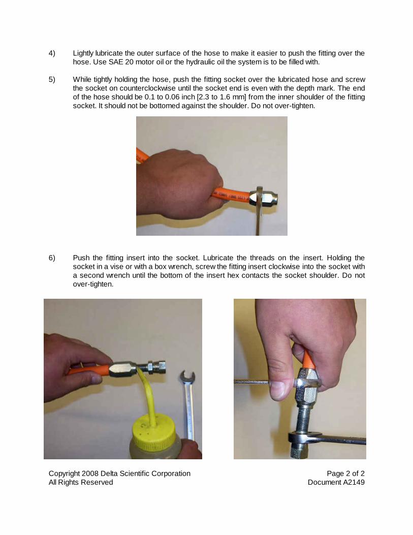
Copyright 2008 Delta Scientific Corporation Page 2 of 2All Rights Reserved Document A2149
4) Lightly lubricate the outer surface of the hose to make it easier to push the fitting over thehose. Use SAE 20 motor oil or the hydraulic oil the system is to be filled with.
5) While tightly holding the hose, push the fitting socket over the lubricated hose and screwthe socket on counterclockwise until the socket end is even with the depth mark. The endof the hose should be 0.1 to 0.06 inch [2.3 to 1.6 mm] from the inner shoulder of the fittingsocket. It should not be bottomed against the shoulder. Do not over-tighten.
6) Push the fitting insert into the socket. Lubricate the threads on the insert. Holding thesocket in a vise or with a box wrench, screw the fitting insert clockwise into the socket witha second wrench until the bottom of the insert hex contacts the socket shoulder. Do notover-tighten.

DESCRIPTION
The Model 257 continuously monitors 3-phase power lines for abnormal conditions. When properly adjusted, the Model 257 monitor will detect phase loss on a loaded motor even when regenerated voltage is present.
This device consists of a solid-state voltage and phase-angle sensing circuit, driving an electro-mechanical relay. When correct voltage and phase rotation are applied, the internal relay will energize. A fault condition will de-energize the relay. When the fault is corrected, the monitor will automatically reset (a manual reset version is also available).
The Model 257 does not require a neutral connection and can be used with Wye or Delta systems. Voltage ranges are sufficiently wide to allow for proper adjustment to existing conditions. Both “TRIP” and “NORM” condition indicators are provided to aid in adjustment and system trouble-shooting.
SPECIFICATIONS
AUTO Reset
MANUAL Reset
B257B
B257BM
257B
257BM
A257B
A257BM
EX257B
EX257BM
B257B-400
B257BM-
400
257B-400
257BM-400
Nominal AC voltage (phase to phase)
120 vac 208/240 vac 480 vac 380 vac 120 vac 208/240 vac
Case Color Gray Red Yellow Yellow Gray Red
Adjustment range 85-120vac 160-240vac 380-480vac 300-400vac 85-120vac 160-240vac
Frequency 60 Hz 60 Hz 60 Hz 50 Hz 400 Hz 400 Hz
Power consumption 0.75W 1.5W 4.5W 3.75W 0.75W 1.5W
Transient protection 2500 VAC for 10msec
Repeat accuracy ± 0.1% of set point (fixed conditions)
Response time 50 msec (set or reset)
Dead band Approximately 2%
Output contacts SPDT 10 amps at 240 VAC resistive
Expected relay life Mechanical: 10 million operations Electrical: 100,000 operations at rated load
Operating temp -40° to +131° F
Humidity tolerance 0 - 97% w/o condensation
Enclosure material Dust cover: ABS plastic
Mounting 8-pin socket ( **sold separately)
Weight 5 ounces
Agency approvals UL Recognized* and CSA Certified *condition of acceptability: the 380V and 480V versions
must be used with a UL Recognized 600 VAC socket
** Order 8-pin socket number 51X120
DIMENSIONS
TYPICAL APPLICATION
ll Detects phase loss, low voltage, phase reversal
ll 50 Hz, 60 Hz and 400 Hz models
ll Automatic or manual reset
ll Five year unconditional warranty
MODEL 257
3-Phase Monitor
TIME MARK is a division of
Telephone: Main - (918) 438-1220 Sales - (800) 862-2875
Fax: (918) 437-7584 E-mail: [email protected] Internet: http://www.time-mark.com
Doc No. 87A189 12/00 © 2000 TIME MARK CORPORATION
11440 East P ine Street Tulsa, Oklahoma 74116

INSTALLATION
Mount the 8-pin socket in a suitable enclosure. A NEMA-1 rated enclosure, designed for socket-mounted relays is available from Time Mark Corporation.
Connect 3-phase power to terminals 3, 4, and 5 on the socket. Phase rotation should be verified using a Time Mark Model 108A or 108B Phase Sequence Detector.
Connect the load control wiring to the appropriate terminals on the socket:
For motor control applications; use terminals 1 and 8. For phase loss alarm applications; use terminals 1 and 2.
Insert the Model 257 into the socket and apply power. If the contact does not transfer (green light ON), check that all phases are present, and of the correct voltage. If power is correct, rotate the level adjustment counter-clockwise.
If the contact still does not transfer, remove power and reverse two of the three phase wires at the socket (phase rotation is reversed). Re-apply power. The contact should transfer to provide a signal path between pins 1 and 8.
NOTE: When installing the Model 257 monitor in areas of high humidity or contamination, it is recommended that the base area and all exposed metal parts of the socket be coated liberally with a good quality silicon grease, such as Dow Corning DC-4 or DC-4X. Insert the unit into the socket and wipe off excess grease around the base. This will prevent the entrance of moisture and other contaminates into the base and socket areas. ADJUSTMENT SETTINGS
The following procedure will allow the Model 257 to be adjusted to achieve a trip point just below the nominal phase-to-phase voltage, where the unit is applied.
Rotate the adjustment control fully clockwise, or until the red (TRIP) indicator illuminates.
Slowly rotate the adjustment control in a counter-clockwise direction, just until the green (NORM) indicator illuminates.
At this point, the Model 257 is the most sensitive to irregular power line conditions. If nuisance tripping occurs, turn the control slightly farther counter-clockwise.
A more accurate setting will require the use of a 3-phase var-iac to lower the voltage to an exact measurable setting. Time Mark also offers a factory set version of all models and voltage ranges, for only a small additional charge. TROUBLESHOOTING
Should the Model 257 Monitor fail to operate properly, check that all three voltages are present, and are of the correct voltage level and phase rotation (a Model 108A or 108B Phase Sequence Detector should be used to verify phase rotation). Check all fuses and verify that all wiring connections are correct. If problems persist, contact your local Time Mark Distribuor, or the factory for assistance (Monday-Friday, 8 a.m. to 5 p.m. CST). MANUAL RESET VERSIONS
IF YOU DO NOT WISH TO USE THE EXTERNAL RESET SWITCH ON THE MANUAL RESET VERSION, YOU MUST JUMPER PINS 6 AND 7. Refer to the Manual Reset 8-pin diagram.
WARRANTY
The Model 257 3-Phase Monitor is warranted to be free from defects in materials and workmanship, and is covered by our exclusive 5-year Unconditional Warranty. If this device fails to operate, for any reason, we will repair or replace it free, for five years from the date of purchase. Contact the Time Mark Sales department, Monday through Friday; 8 a.m. to 5 p.m., CST, for further details.
MODEL 257 3-Phase Monitor
READ ALL INSTRUCTIONS BEFORE INSTALLING, OPERATING OR SERVICING THIS DEVICE. KEEP THIS DATA SHEET FOR FUTURE REFERENCE.
GENERAL SAFETY
POTENTIALLY HAZARDOUS VOLTAGES ARE PRESENT AT THE TERMINALS OF THE MODEL 257. ALL ELECTRICAL POWER SHOULD BE REMOVED WHEN CONNECTING OR DISCONNECTING WIRING.
THIS DEVICE SHOULD BE INSTALLED AND SERVICED BY QUALIFIED PERSONNEL.
Installation Instructions
TIME MARK is a division of
Telephone: Main - (918) 438-1220 Sales - (800) 862-2875
Fax: (918) 437-7584 E-mail: [email protected] Internet: http://www.time-mark.com
Doc No. 87A189 12/00 © 2000 TIME MARK CORPORATION
11440 East P ine Street Tulsa, Oklahoma 74116
WARNING
IN APPLICATIONS WHERE VOLTAGES IN EXCESS OF 300 VAC ARE TO BE MONITORED, BE CERTAIN TO USE THE TIME MARK MODEL 51X120 8-PIN SOCKET, OR AN EQUIVALENT UL APPROVED 600 VAC RATED SOCKET.

Copyright 2009 Delta Scientific Corporation Page 1 of 4All Rights Reserved Document A2025.2
ACCUMULATOR PRECHARGE PROCEDURE
Use an inert gas such as Nitrogen for precharging accumulators. If oil pumped is not available,dry water pumped Nitrogen gas may be used. Note: Do Not Use Air or Oxygen, theAccumulator Could Explode!
Before precharging, make certain that the accumulator gas valve is screwed in tight. Check thatthe hydraulic pressure is a zero on the oil pressure gage. Precharging the accumulator whileunder pressure will result in an incorrect precharge pressure.
Check the precharge value on the accumulator’s label or on the HPU’s Flysheet. Thefollowing values are a guide only and may be modified in some instances to provide certain barrierperformance.
DSC800, TT203 & TT210 Bollards 500 PSIGDSC720 Bollards 700 PSIGTT205 & TT207 Phalanx 700 PSIGDSC501, TT207S & TT207S/FM Phalanx 850 to 1100 PSIGDSC1100 700 to 1000 PSIGDSC1200 900 to 1000 PSIGDSC1400 1000 PSIGDSC2000 700 PSIGDSC7000(H) 900 PSIGTT224, TW107, TW108, TW2015 and TW4030 Phalanx 700 PSIGTT270 Hydraulic Gate Operator 800 PSIGTT212H, TT212E(H) & BB10M Beam Barriers 600 to 700 PSIGTT212EC(H) & (M), IP500(H) & (M) 600 to 1300 PSIG
CAUTIONS:
1. Do not loop or twist the hose, as it will stiffen when gas pressure is released from the nitrogengas bottle.
2. Never loosen swivel nut attached to the accumulator gas valve without first backing the GasChuck stem out all the way.
3. Do not reduce accumulator precharge pressure by depressing accumulator gas valve core(the highpressure gas may rupture the rubber valve seat). Instead, slowly turn gas valve outuntil gas begins to escape through the bleed hole drilled through the threads of the valve. Thishole is a safety feature, warning of stored pressure whenever the gas valve is being removed.Install a new gas valve 'o'ring each time the gas valve is removed.
Copyright 2009 Delta Scientific Corporation Page 2 of 4All Rights Reserved Document A2025.2
Note: During this procedure, refer to the diagrams on page 4.
Determining the Current Pressure in the Accumulator:
1. Remove the gas valve guard. Ensure that the valve is closed on the Nitrogen gas bottle andattach the accumulator charge kit’s hose to the nitrogen bottle.
2. Attach the gauge assembly to the hose. Back out the Gas Chuck stem all the way by turningthe Thandle (counterclockwise) before attaching to accumulator.
3. Using a 3/4inch wrench, hold the top hex on the accumulator’s gas valve, and remove theyellow cap with 3/8inch wrench.
4. Holding top hex on the accumulator’s gas valve with a 3/4inch wrench, attach the gas chuckon the gauge assembly to the gas valve on the accumulator. Secure the gauge assembly gaschuck to the accumulator gas valve with an 11/16inch wrench. (Position of the tee handle ongas chuck should be fully turned counterclockwise.)
5. Turn the Thandle on the gas chuck until the stem is all the way up (counterclockwise).
6. Ensure that the bleeder valve on the gauge assembly is closed.
7. Turn the Thandle on the gas chuck until the stem is all the way down (clockwise) which willdepress the accumulator gas valve core.
8. Be certain that the bleeder valve is closed.
9. Using a 3/4 inch wrench, hold bottom hex on accumulator gas valve, and slowly turn top hexon the gas valve counterclockwise with second 3/4 inch wrench until the valve is open. Thegauge will show precharge pressure.
10. Check the pressure on the gauge. If the gauge pressure matches the recommended precharge pressure for your barrier proceed to step 13.
Adjusting the Precharge Pressure in the Accumulator:
11. If the precharge pressure needs to beincreased, slightly crack open the valve on theNitrogen gas bottle to slowly fill the accumulator. Close the valve when the gage indicates thedesired precharge pressure.
DANGER! NEVER EXCEED THE MAXIMUM ALLOWABLE WORKING PRESSURE OF THEPRESSURE VESSEL.
12. If the gauge pressure exceeds the desired precharge pressure is exceeded, ensure that thevalve on the Nitrogen gas bottle is closed and then open bleeder valve slightly to reducepressure.

Copyright 2009 Delta Scientific Corporation Page 3 of 4All Rights Reserved Document A2025.2
Note: Allow accumulator to rest 1015 minutes after gas precharging. This will allow the gastemperature to adjust and equalize. Recheck gas pressure and adjust as necessary.
Removing the Precharge Kit:
13. Using a 3/4 inch wrench, hold bottom hex on accumulator gas valve, and slowly turn top hexon the gas valve clockwise with second 3/4 inch wrench until the valve is closed.
14. Before loosening the gas valve swivel nut, turn the Thandle on the gas chuck until the stemout all the way (counterclockwise)
15. Ensure that the valve on the Nitrogen bottle is closed and then Slowly open bleed valve ongauge assembly. Relieve pressure in the hose assembly until gauge reads zero.
16. Holding top hex on the accumulator’s gas valve with a 3/4inch wrench, remove the gas chuckon the gauge assembly to the gas valve on the accumulator with an 11/16inch wrench.
17. Install yellow gas valve cap on accumulator.
18. Install spacer (optional) and the gas valve guard on accumulator with the supplied 3/8inch hexbolts.
DANGER! NEVER OPERATE ACCUMULATOR WITHOUT GAS VALVE GUARD INSTALLED.
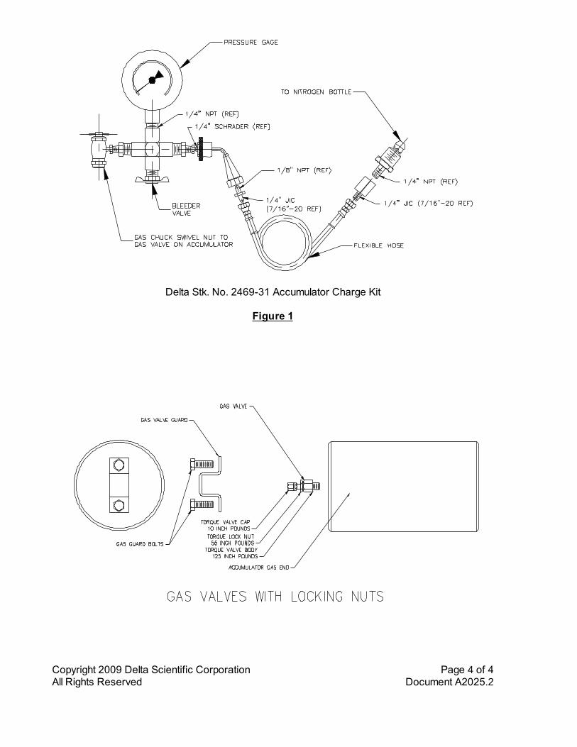
Copyright 2009 Delta Scientific Corporation Page 4 of 4All Rights Reserved Document A2025.2
Delta Stk. No. 246931 Accumulator Charge Kit
Figure 1
Figure 2
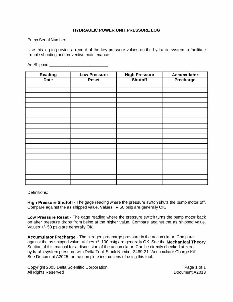
Copyright 2005 Delta Scientific Corporation Page 1 of 1All Rights Reserved Document A2013
HYDRAULIC POWER UNIT PRESSURE LOG
Pump Serial Number: _____________
Use this log to provide a record of the key pressure values on the hydraulic system to facilitatetrouble shooting and preventive maintenance:
As Shipped: - -
Reading Low Pressure High Pressure AccumulatorDate Reset Shutoff Precharge
Definitions:
High Pressure Shutoff - The gage reading where the pressure switch shuts the pump motor off.Compare against the as shipped value. Values +/- 50 psig are generally OK.
Low Pressure Reset - The gage reading where the pressure switch turns the pump motor backon after pressure drops from being at the higher value. Compare against the as shipped value.Values +/- 50 psig are generally OK.
Accumulator Precharge - The nitrogen precharge pressure in the accumulator. Compareagainst the as shipped value. Values +/- 100 psig are generally OK. See the Mechanical TheorySection of this manual for a discussion of the accumulator. Can be directly checked at zerohydraulic system pressure with Delta Tool, Stock Number 2469-31 "Accumulator Charge Kit".See Document A2025 for the complete instructions of using this tool.
Copyright 2007 Delta Scientific Corporation Page 1 of 1All Rights Reserved Document A2012.4
SPARE PARTS ORDERING INFORMATION
Insurance or breakdown spares can be obtained locally or from Delta Scientific Corporation asdesired. If parts are found locally, they should be of the same manufacture and pattern as theoriginal part. On hydraulic systems, we do not recommend the replacement of the main directionalvalve by any other manufacturer than Vickers/Double A or Rexroth.
When ordering parts from the factory, please specify the Model of the Barriers and the serialnumber. If these are not known, the original order number and date of purchase of the systemshould be given.
(Serial numbers are located on the equipment nameplates on the HPU and in the Barrier accessarea. The Model number of the system is also shown on the nameplate. Electrical control panelsand circuits reference the appropriate drawing number; please provide this number when orderingcontrol components.)
Use the numbers on the attached spare parts list as well as the actual component'smanufacturers' number. Give as complete a description of the part and its function as possible. Ifuncertain as to the parts name or function, a sketch should be mailed or FAXED with the order.
Most parts are maintained in stock and can be processed for shipment within one week of order.If parts are for breakdown replacement, please note on order so that we may expedite shipment.If parts are not in stock, we will confirm your order with an expected delivery date.
Prices shown are net each, FOB Palmdale, California. Prices are subject to change withoutnotice.
Contact:
Delta Scientific Corporation40355 Delta LanePalmdale, California 93551Phone (661)575-1100Fax (661)575-1109E-MAIL [email protected]

DELTA SCIENTIFIC CORPORATION PHONE 661-575-110040355 DELTA LANE FAX 661-575-1109PALMDALE, CALIFORNIA, 93551, USA EMAIL [email protected]@deltascientific.com
SPARE PARTS LIST – JOBS 7584A-CDELTA MODEL DSC720-CA BOLLARD BARRIERS
PRICES SUBJECT TO CHANGE WITHOUT NOTICE.PRICES ARE NET 30 DAYS TO APPROVED ACCOUNTS, FOB PALMDALE, CALIFORNIA.SEE ORDERING INSTRUCTIONS TO ASSURE THAT PROPER PARTS ARE ORDERED.
Copyright 2010 Delta Scientific Corporation Page 1 of 3All Rights Reserved Document J7584A-C Spare Parts
ELECTRICAL PARTS EFFECTIVE September 1, 2010
STK NO. DESCRIPTION UNIT COST2459-16 FUSE, 250 V, 10 AMP, 5/PKG, $ 8.532459-119 FUSE, 250 V, 3.5 AMP, 5/PKG, 8.532461-29 POWER SUPPLY, 240 WATTS, 380.882461-40 BATTERY, 12 VOLT, 7 A-H, 55.002463-01 KEY SWITCH, 61.162463-01K KEY, KEY SWITCH, 6.602463-02A SELECTOR SWITCH, 6.782463-03A EFO, HOODED TOGGLE TYPE, 44.262463-04A EFO, LARGE GUARD TYPE, 48.402463-06 PUSHBUTTON, N.O. BLACK, 13.862463-07 PUSHBUTTON, N.C. RED, 15.402463-16 PILOT LIGHT, LED, RED, 17.202463-17 PILOT LIGHT, LED, GREEN, 17.202463-63 ANNUNCIATOR SIREN, 44.542464-165 MOTOR, 5 HP @ 240/3/60, 834.532465-08 PRESSURE SWITCH, 1400/1900 230.082465-11 RESERVOIR LEVEL SWITCH, 157.082465-27 LIMIT SWITCH ASSY, MAGNETIC, 43.732465-64 3 PHASE POWER MONITOR, 215.602465-107 DIN HARNESS - BRN/BLU/GRN 38.502467-01 DIRECT. VALVE, DO3, 24 VDC, 400.692467-31 EFO VALVE, 168.042467-100 DIN HARNESS, BLK, WHT, GRN, 15.952467-101 DIN HARNESS, RED, WHT, GRN, 15.952531-67 STARTER OVERLOAD, 5.4-27 A, 123.202531-107 MOTOR STARTER, 153.512531-113 DISCONNECT SWITCH, 30 AMP, 211.202534-68 TIMER RELAY TRIM POT, 2.202534-69 TIMER RELAY, 24 VDC, 84.087195-FU1 FUSE, 2 AMPS, FAST ACTING 1.007195-V1 VOLTAGE REGULATOR, 12 V, 0.8990605-00 MAIN CONTROL BOARD, 583.00IN5404 DIODE 2.201/4W1.2K RESISTOR 2.20MANUAL OWNERS MANUAL SERIAL NUMBER 7584A-C 65.00

DELTA SCIENTIFIC CORPORATION PHONE 661-575-110040355 DELTA LANE FAX 661-575-1109PALMDALE, CALIFORNIA, 93551, USA EMAIL [email protected]@deltascientific.com
SPARE PARTS LIST – JOBS 7584A-CDELTA MODEL DSC720-CA BOLLARD BARRIERS
PRICES SUBJECT TO CHANGE WITHOUT NOTICE.PRICES ARE NET 30 DAYS TO APPROVED ACCOUNTS, FOB PALMDALE, CALIFORNIA.SEE ORDERING INSTRUCTIONS TO ASSURE THAT PROPER PARTS ARE ORDERED.
Copyright 2010 Delta Scientific Corporation Page 2 of 3All Rights Reserved Document J7584A-C Spare Parts
MECHANICAL PARTS EFFECTIVE September 1, 2010
STK NO. DESCRIPTION UNIT COST2464-32 MOTOR/PUMP ADAPTER, $ 167.202464-52 MOTOR HALF COUPLING, 29.742464-53 PUMP HALF COUPLING, 29.742464-61 COUPLING SPIDER, 14.342465-05 PRESSURE RELIEF VALVE, 103.002465-21 PRESSURE GAGE, 0-3000 PSIG, 50.952465-22 LEVEL GAGE, 10", 68.772465-23 GAGE SNUBBER, 31.502465-91 TOOL KIT IN TOOL BOX, 269.642466-11B 1/4" NEEDLE VALVE, 65.472466-12B 3/8" NEEDLE VALVE, 80.082466-33B 1/2" BALL VALVE, BRONZE, 35.022467-72 MANIFOLD, DO3-2 STATION 339.172467-94 VALVE MOUNTING BOLT SET, 2.202469-31 ACCUM CHARGE KIT, 239.032469-51 ACCUM CHARGE BOTTLE, 258.502469-94 ACCUMULATOR, 5.0 GALLON, 1,419.002469-96 ACCUM REBUILD KIT, 6 INCH, 451.002470-22 FILTER HOUSING & ELEMENT, 624.552470-32 FILTER ELEMENT, PRESSURE, 174.902470-41 SUCTION STRAINER, 30.492470-43 FILLER BREATHER, 40.132471-21 HAND PUMP, COMPLETE, 417.932471-27 PUMP, 0.258 CU IN/REV, 377.562471-27S PUMP SEAL KIT, SHAFT & CRES. 41.182471-31 HAND PUMP, SEAL KIT, 59.402512-4-FT HOSE ASSY, 1/4" X xx FT LG, $ 5.41/FT + 27.622512-6-FT HOSE ASSY, 3/8" X xx FT LG, $ 5.68/FT + 28.822512-8-FT HOSE ASSY, 1/2" X xx FT LG, $ 6.12/FT + 30.302512-45T HOSE FIELD FITTING, JIC 04 55.602512-46T HOSE FIELD FITTING, JIC 06 61.362512-47T HOSE FIELD FITTING, JIC 08 81.167002-1 GASKET, OIL TANK COVER, 8.16
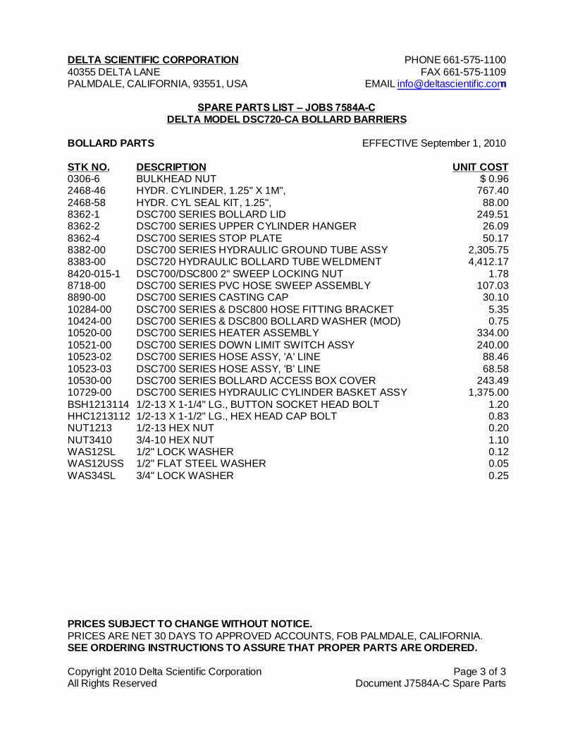
DELTA SCIENTIFIC CORPORATION PHONE 661-575-110040355 DELTA LANE FAX 661-575-1109PALMDALE, CALIFORNIA, 93551, USA EMAIL [email protected]@deltascientific.com
SPARE PARTS LIST – JOBS 7584A-CDELTA MODEL DSC720-CA BOLLARD BARRIERS
PRICES SUBJECT TO CHANGE WITHOUT NOTICE.PRICES ARE NET 30 DAYS TO APPROVED ACCOUNTS, FOB PALMDALE, CALIFORNIA.SEE ORDERING INSTRUCTIONS TO ASSURE THAT PROPER PARTS ARE ORDERED.
Copyright 2010 Delta Scientific Corporation Page 3 of 3All Rights Reserved Document J7584A-C Spare Parts
BOLLARD PARTS EFFECTIVE September 1, 2010
STK NO. DESCRIPTION UNIT COST0306-6 BULKHEAD NUT $ 0.962468-46 HYDR. CYLINDER, 1.25" X 1M", 767.402468-58 HYDR. CYL SEAL KIT, 1.25", 88.008362-1 DSC700 SERIES BOLLARD LID 249.518362-2 DSC700 SERIES UPPER CYLINDER HANGER 26.098362-4 DSC700 SERIES STOP PLATE 50.178382-00 DSC700 SERIES HYDRAULIC GROUND TUBE ASSY 2,305.758383-00 DSC720 HYDRAULIC BOLLARD TUBE WELDMENT 4,412.178420-015-1 DSC700/DSC800 2" SWEEP LOCKING NUT 1.788718-00 DSC700 SERIES PVC HOSE SWEEP ASSEMBLY 107.038890-00 DSC700 SERIES CASTING CAP 30.1010284-00 DSC700 SERIES & DSC800 HOSE FITTING BRACKET 5.3510424-00 DSC700 SERIES & DSC800 BOLLARD WASHER (MOD) 0.7510520-00 DSC700 SERIES HEATER ASSEMBLY 334.0010521-00 DSC700 SERIES DOWN LIMIT SWITCH ASSY 240.0010523-02 DSC700 SERIES HOSE ASSY, 'A' LINE 88.4610523-03 DSC700 SERIES HOSE ASSY, 'B' LINE 68.5810530-00 DSC700 SERIES BOLLARD ACCESS BOX COVER 243.4910729-00 DSC700 SERIES HYDRAULIC CYLINDER BASKET ASSY 1,375.00BSH1213114 1/2-13 X 1-1/4" LG., BUTTON SOCKET HEAD BOLT 1.20HHC1213112 1/2-13 X 1-1/2" LG., HEX HEAD CAP BOLT 0.83NUT1213 1/2-13 HEX NUT 0.20NUT3410 3/4-10 HEX NUT 1.10WAS12SL 1/2" LOCK WASHER 0.12WAS12USS 1/2" FLAT STEEL WASHER 0.05WAS34SL 3/4" LOCK WASHER 0.25

COPYRIGHT 2010 DELTA SCIENTIFIC CORPORATIONALL RIGHTS RESERVED DOCUMENT 90450 FS J7584A-C
DRAWING 90450 FLY-SHEET
DELTA JOB NUMBER: 7584A-C
CUSTOMER: ANIXTER INC.P.O. 597-598617-431US EMBASSY – PORT OF SPAIN, TRINIDAD & TOBAGO
DATE: September 1, 2010
THIS FLY-SHEET COVERS JOB SPECIFIC TABULATIONS TO DELTA DRAWING 90450.
S/N 7584A-1 THROUGH 7584A-4,7584B-1 THROUGH 7584B-4,
AND 7584C-1 THROUGH 7584C-5(THIRTEEN DSC720-CA BOLLARDS)
'A' OPTION BOLLARD HEATER: NO BOLLARD HEATER
'B' OPTION LIMIT SWITCH: B2015, FULLY DOWN POSITION
'C' OPTION LIMIT SWITCH: NO FULLY UP LIMIT SWITCH
'D' OPTION PILOT CHECK VALVE: NO P.O. CHECK VALVE
DECORATIVE CASTING: YES, STYLE ‘CA’
BOLLARD SURFACE PREPARATION: ZINC RICH PRIMER
BOLLARD COLOR SCHEME: BENJAMIN-MOORE BRONZETONE 64


COPYRIGHT 2010 DELTA SCIENTIFIC CORPORATIONALL RIGHTS RESERVED DOCUMENT 90503-4 FS J7584A-B
DRAWING 90503-4 FLY-SHEET
DELTA JOB NUMBER: 7584A-B
CUSTOMER: ANIXTER INC.P.O. 597-598617-431US EMBASSY – PORT OF SPAIN, TRINIDAD & TOBAGO
DATE: September 1, 2010
THIS FLY-SHEET COVERS JOB SPECIFIC TABULATIONS TO DELTA DRAWING 90503-4.
S/N 7584A-HPU AND 7584B-HPU(TWO HYDRAULIC POWER UNITS)
'H' HORSEPOWER @ 'V' MOTOR VOLTAGE: 5 HP @ 240/3/60
'M' MOTOR STOCK NUMBER: 2464-165
B1325 HANDPUMP OPTION: YES, STOCK NUMBER 2471-21
B1020 AUXILIARY EFO OPTION: NO AUXILIARY EFO
NUMBER OF ACCUMULATORS: TWO (10 GALLONS TOTAL)
ACCUMULATOR PRECHARGE PRESSURE: 700 PSIG DRY NITROGEN
FILTER ELEMENT/HOUSING TYPE: PRESSURE TYPE, STOCK NUMBER 2470-22
B1190/B1191 OIL HEATER OPTION: NO OIL HEATER
B1195/B1196 OIL COOLER OPTION: NO OIL COOLER
MOTOR STARTER DRAWING NUMBER: 90610-2/C
B1260 DISCONNECT OPTION: YES, STOCK NUMBER 2531-113
WEIGHT, POUNDS [KG]: 760 POUNDS [345 KG]
HPU ENCLOSURE: YES, STOCK NUMBER B1218 (WHITE)
WEIGHT IN ENCLOSURE, POUNDS [KG]: 1,135 POUNDS [516 KG]

0N
OFF

COPYRIGHT 2010 DELTA SCIENTIFIC CORPORATIONALL RIGHTS RESERVED DOCUMENT 90503-5 FS J7584C
DRAWING 90503-5 FLY-SHEET
DELTA JOB NUMBER: 7584C
CUSTOMER: ANIXTER INC.P.O. 597-598617-431US EMBASSY – PORT OF SPAIN, TRINIDAD & TOBAGO
DATE: September 1, 2010
THIS FLY-SHEET COVERS JOB SPECIFIC TABULATIONS TO DELTA DRAWING 90503-5.
S/N 7584C-HPU(ONE HYDRAULIC POWER UNIT)
'H' HORSEPOWER @ 'V' MOTOR VOLTAGE: 5 HP @ 240/3/60
'M' MOTOR STOCK NUMBER: 2464-165
B1325 HANDPUMP OPTION: YES, STOCK NUMBER 2471-21
B1020 AUXILIARY EFO OPTION: NO AUXILIARY EFO
NUMBER OF ACCUMULATORS: TWO (10 GALLONS TOTAL)
ACCUMULATOR PRECHARGE PRESSURE: 700 PSIG DRY NITROGEN
FILTER ELEMENT/HOUSING TYPE: PRESSURE TYPE, STOCK NUMBER 2470-22
B1190/B1191 OIL HEATER OPTION: NO OIL HEATER
B1195/B1196 OIL COOLER OPTION: NO OIL COOLER
MOTOR STARTER DRAWING NUMBER: 90610-2/C
B1260 DISCONNECT OPTION: YES, STOCK NUMBER 2531-113
WEIGHT, POUNDS [KG]: 760 POUNDS [345 KG]
HPU ENCLOSURE: YES, STOCK NUMBER B1218 (WHITE)
WEIGHT IN ENCLOSURE, POUNDS [KG]: 1,135 POUNDS [516 KG]
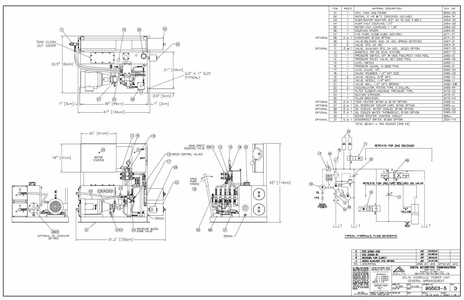
0N
OFF
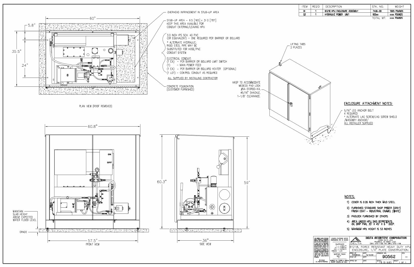
0N
OFF


COPYRIGHT 2010 DELTA SCIENTIFIC CORPORATIONALL RIGHTS RESERVED DOCUMENT 90610-2 FS J7584A-C
DRAWING 90610-2 FLY-SHEET
DELTA JOB NUMBER: 7584A-C
CUSTOMER: ANIXTER INC.P.O. 597-598617-431US EMBASSY – PORT OF SPAIN, TRINIDAD & TOBAGO
DATE: September 1, 2010
THIS FLY-SHEET COVERS JOB SPECIFIC TABULATIONS TO DELTA DRAWING 90610-2.
S/N 7584A-CC, 7584B-CC, AND 7584C-CC(THREE CONTROL CIRCUITS)
'H' HORSEPOWER @ 'R' MOTOR RPM: 5 HP @ 3450 RPM
'V' MOTOR VOLTAGE: 240/3/60
'FL' MOTOR FULL LOAD AMPS: 12 AMPS
'CV' CONTROL CIRCUIT VOLTAGE: 120/1/60
'W' POWER SUPPLY WATTAGE: 240 WATTS, STOCK NUMBER 2461-29
'1FU'/’PA’ FUSE AND STOCK NUMBER: 3.5 AMPS, STOCK NUMBER 2459-119
'2FU'/’SA’ FUSE AND STOCK NUMBER: 10 AMPS, STOCK NUMBER 2459-16
'3FU'/'RHA' FUSE AND STOCK NUMBER: NO OIL HEATER
‘RW’ OIL HEATER WATTS: NO OIL HEATER
'4FU-9FU'/'BHA' FUSE AND STOCK NUMBER: NO BOLLARD HEATERS
‘HW’ BOLLARD HEATER WATTS: NO BOLLARD HEATERS
WIRE COLOR CODE: USA
B1255 POWER MONITOR OPTION: YES, STOCK NUMBER 2465-64
B1260 DISCONNECT OPTION: YES, STOCK NUMBER 2531-113
STARTER STOCK NUMBER: 2531-107 (A-B 100-C16KD10)
OVERLOAD STOCK NUMBER: 2531-67 (A-B 193-ED1EB)
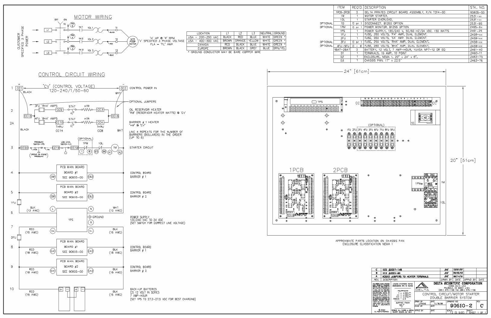


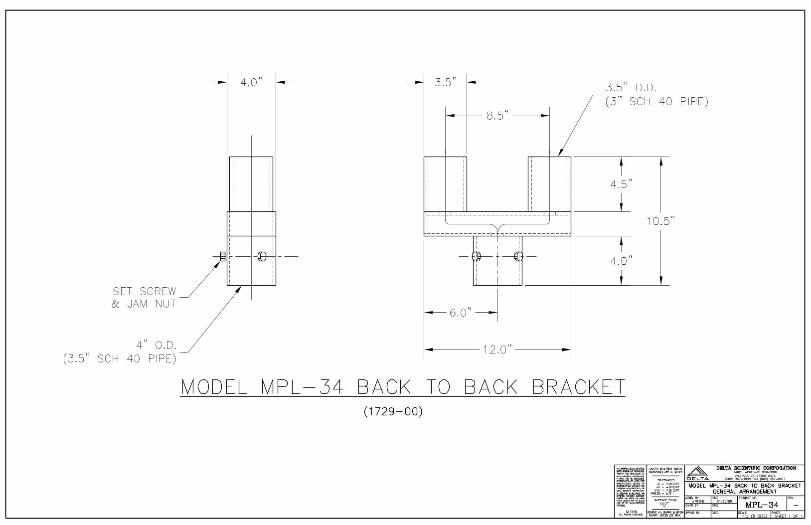


DELTA DIGITAL VEHICLE DETECTORS DOCUMENT A2075OPERATING INSTRUCTIONS – SERIES 3546
40355 Delta Lane – Palmdale, California, 93551, USA – Phone: (661) 575-1100 – Fax: (661) 575-1109
THIS DELTA DIGITAL VEHICLE DETECTOR, WHICHINCORPORATES AN ADVANCED MICROCONTROLLER, COMBINES A POWERFUL DIGITALCOMPUTER AND THE LATEST AND MOSTADVANCED INDUCTIVE VEHICLE LOOPTECHNOLOGY TO GIVE THE TRAFFIC, PARKINGOR SECURITY PROFESSIONAL THE FINEST INRELIABILITY, FLEXIBILITY AND ACCURACY WHENMEASURING, COUNTING OR DETECTINGVEHICLES.
WARNING!!! THERE ARE MANY DIFFERENTWIRING CONFIGURATIONS. FAILURE TO MATCHTHE CONNECTIONS OF MALFUNCTION OF THEDETECTOR SERIES AND THE HARNESS CANRESULT IN MALFUNCTION OF THE DETECTORAND SYSTEM.
Installation: Plug the detector into a harness or panelwired in accordance with the chart of connections listedon the detector label or in accordance with the chart ofconnections for the specific detector.
Apply power to the detector. The detector will tune andbe operation immediately thereafter.
Field Selective Features: A detector can be configuredto meet and satisfy a wide range of operating andinterface situations. The following programming optionsare for all Delta detectors.
Multiple Loop Installations: (frequency settings) Thedetectors for adjacent loops should be set at differentfrequencies in installations where several loops of thesame approximate size and number of turns areoperated in close proximity. This will eliminate or greatlyreduce the possibility of cross talk between thedetectors. A high, low or medium frequency range isselected by the three-position toggle switch.
Sensitivity: The sensitivity is factory set at level 5 andin most installations will not have to be changed.Sensitivity can be increased or decreased by means ofa 10 position rotary switch located on the PCB of thedetector. Level ‘9’ is the highest sensitivity and level ‘0’the lowest (factory setting level ‘5’).
Automatic Profile Tracking: (Standard on Deltadetectors) With profile tracking, the detectorautomatically tracks the profile of high bed vehicles andadjusts its sensitivity so that it will hold the vehicle aslong as it is over the loop, thus reducing the possibilitythat the detector will drop the “call” (no field adjustmentneeded).
Re Self-Tune Hold Time: (Ref. Dwg. ‘A’)PROGRAMMING JUMPER #4 INSTALLED, HOLDTIME BEFORE RE-TUNE IS 2 HOURS.PROGRAMMING JUMPER #4 REMOVED, HOLDTIME BEFORE RE-TUNE IS INFINITY.(Time after self-tuning that the detector will wait after asteady call before re-tuning to the new condition.)
Fail Safe/ Fail Secure Options (Ref Dwg ‘B’)PROGRAMMING JUMPER #3 INSTALLED,DETECTOR OUTPUTS ARE FAIL-SAFE.PROGRAMMING JUMPER #3 REMOVED ORSEVERED, DETECTOR OUTPUTS ARE FAILSECURE.
Loop Self Diagnostics (See Note No. 1) (Ref Dwg ‘B’)WITH JUMPER IN POSITION AS SHOWN, SELF-DIAGNOSTICS ENABLED.WITH JUMPER REMOVED OR SEVERED, SELF-DIAGNOSTICS DEACTIVATED.
Dual Relay Detectors: In addition to the above fieldprogramming features, dual relay detectors can beprogrammed as follows:
Pulse Relay-Pulse on Exit or Pulse on Entrance:(Ref Dwg ‘B’)PROGRAMMING JUMPER #2 INSTALLED, PULSEOUTPUT ON ENTRY TO LOOP.PROGRAMMING JUMPER #2 REMOVED, PULSEOUTPUT ON EXIT FROM LOOP.
Single Relay Detectors: In addition to the above fieldprogramming features, single relay detectors can beprogrammed as follows:
Pulse or Presence Output Options: (Ref Dwg ‘A’)PROGRAMMING JUMPER #1 AND PROGRAMMINGJUMPER #3 INSTALLED, RELAY OPERATES INPRESENCE MODE.PROGRAMMING JUMPER #1 REMOVED, RELAYOPERATES IN PULSE MODE.
Pulse on Entrance or Pulse on Exit: (Ref Dwg ‘A’)WHEN OPERATED IN THE PULSE MODE WITHPROGRAMMING JUMPER #2 AND PROGRAMMINGJUMPER #3 INSTALLED, PULSE OUTPUT ONENTRANCE TO LOOP.PROGRAMMING JUMPER #2 REMOVED, PULSEOUTPUT ON EXIT FROM LOOP.
Note No. 1: When this feature is enabled and thedetector is powered up, the LED lights momentarilywhile the detector self-tunes. After tuning, the LED willlight when the detector signals a “call”.
If the LED commences a repeated series of flashes, thisindicates that the loop is probably shorted (series offlashes followed by a pause) or the loop is open (steadyseries of flashes). If the problem is intermittent and selfheals, the detector will resume normal operations.However, the fault signal will continue until the detectoris reset by either the front panel reset button or byturning off the power momentarily. When the self-diagnostics is deactivated the detector is powered up;the LED lights momentarily while the detector selftunes. After tuning, the LED will light when the detectorsignals a “call”.
Note No. 2: The detector can be reset by pressing thered button on the detector case or by momentarilytuning the power off and then back on.

DELTA DIGITAL VEHICLE DETECTORS DOCUMENT A2075OPERATING INSTRUCTIONS – SERIES 3546
40355 Delta Lane – Palmdale, California, 93551, USA – Phone: (661) 575-1100 – Fax: (661) 575-1109
Loop Layouts and Configuration:
DELTA detectors will tune and operate successfullywith loops in a wide range of shapes and sizes such assquares, rectangles, circular, quadruple and diamondshape, etc.
The following chart is a guide to the number of turns touse when installing standard square, rectangular ordiamond shape loops.
Compute the area of the proposed loop in square feet(square meters) and then using the chart, lookup theappropriate number of turns.
Area Square Ft Square Meters Turns
5-14 (,46-1,3) 6
15-20 (1,-1,9) 5
20-64 (1,9-6.0) 4
65-250 (6,0-23.2) 3
Over 250 (23,2) 2
When the lead-in distance from loop to detectorexceeds 490 feet (125m) it is recommended that anadditional turn be added to the loop.
When winding the loop, care should be exercised thatthe wire insulation is protected from scuffing or cutswhile being inserted into the saw slot. Where possibleavoid sharp comers by saw cutting small diagonals ateach corner of the loop. A standard stranded cooperwire with good all condition insulation should be used(#12 to #16 AWG).
The lead-in from the loop to the detector should betwisted (4 twist per foot medium) and shielded ifavailable. The shield should be properly grounded andweather protected at the junction box.
Good low resistance electrical connections at alljunction points of the loop are important. Wherepossible connections or splices should be soldered orbonded together by means of positive flow crimp typeconnectors (no wire nuts). Physical protection of theconnection points against corrosion or contaminationalso contributes to long term operation.

Copyright 2003 Delta Scientific Corporation Page 1 of 8All Rights Reserved Document: DSC LA2075.1
LOOP APPLICATION NOTESVEHICLE DETECTOR LOOP INSTALLATION GUIDE
INTRODUCTION:
This loop application note is intended to illustrate the steps involved in installing a “saw cut type”vehicle detector loop. The loop sizes and configurations vary according to the detectorrequirement being accommodated. Longlength or multiple loops may be required in conjunctionwith traffic signals where the important factor is to know if there is at least one vehicle in a largezone of detection such as a leftturn lane. The smaller loop size (such as 18 inch by 54 inch) isused where it is important to have a separate detection output for each vehicle in a slowmovingstream of heavy traffic, such as a parking gate.
General Notes:
We recommend using a 12 to 16 gauge THHN or better stranded wire. Backer rod is not commonly used anymore, but may be used if available. Wire loop and twisted leadin wire should be one (1) piece. It is best to not splice the loop
and lead wires. Solder all wire connections at the connector (harness) of the loop detector. Do not use wire
nuts to make connection. Asphalt patching compound can be substituted for epoxy, and is typically supplied in
caulking gun tubes.
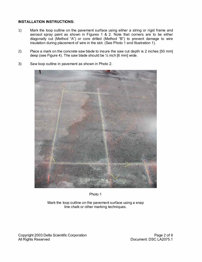
Copyright 2003 Delta Scientific Corporation Page 2 of 8All Rights Reserved Document: DSC LA2075.1
INSTALLATION INSTRUCTIONS:
1) Mark the loop outline on the pavement surface using either a string or rigid frame andaerosol spray paint as shown in Figures 1 & 2. Note that corners are to be eitherdiagonally cut (Method “A”) or core drilled (Method “B”) to prevent damage to wireinsulation during placement of wire in the slot. (See Photo 1 and Illustration 1).
2) Place a mark on the concrete saw blade to insure the saw cut depth is 2 inches [50 mm]deep (see Figure 4). The saw blade should be ¼ inch [6 mm] wide.
3) Saw loop outline in pavement as shown in Photo 2.
Photo 1
Mark the loop outline on the pavement surface using a snapline chalk or other marking techniques.
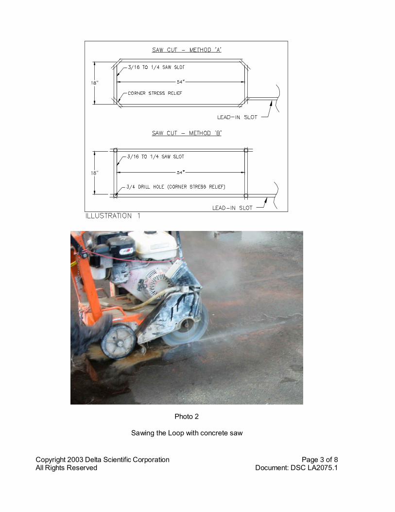
Copyright 2003 Delta Scientific Corporation Page 3 of 8All Rights Reserved Document: DSC LA2075.1
Photo 2
Sawing the Loop with concrete saw

Copyright 2003 Delta Scientific Corporation Page 4 of 8All Rights Reserved Document: DSC LA2075.1
4) Clean debris from slot with water or compressed air and allow surface to completely dry(See Photo 3).
Photo 3
Loop is sawn, debris removed from the saw slot and ready to dry
5) After the loop size has been determined, refer to Illustration 2 to determine the numberof turns of loop wire to be placed in the loop slot. It is important that the proper numberof turns is used. Wire should be minimum 16 gauge in size and should be stranded type.
NOTE: NO WIRE SPLICES ARE PERMITTED IN THE SAW SLOT!!!

Copyright 2003 Delta Scientific Corporation Page 5 of 8All Rights Reserved Document: DSC LA2075.1
6) Calculate the total footage of wire needed to accommodate both the proper number ofturns around the loop PLUS SUFFICIENT FOOTAGE TO PROVIDE BOTH LEADSINTO THE LOOP FROM THE LOOP DETECTOR HARNESS. Leaving enough wire atthe proposed location of the Detector Harness, carefully start to install the wire in theloop slot (see Photo 4) and then make the proper number of turns around the loop.When the loop is complete begin twisting the loop leads together a minimum of 5 turnsper foot (a drill motor is handy for doing this). Continue twisting these wires together allthe way to the connection point with the Detector harness. All caution must be usedwhen installing wire not to cut or nick the wire insulation while placing it in the ground.
Typical turn pattern
One wire in, one wire out (twisted pair)
Multiple turns of wire (use chart for number of turns)
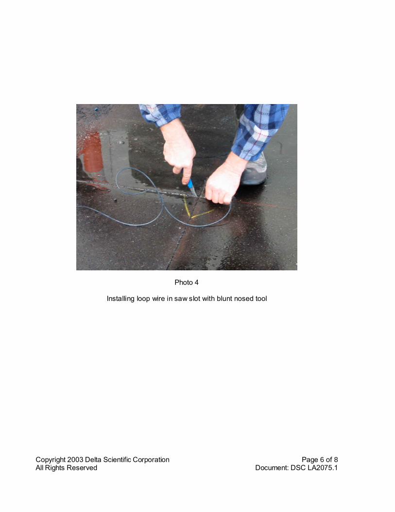
Copyright 2003 Delta Scientific Corporation Page 6 of 8All Rights Reserved Document: DSC LA2075.1
Photo 4
Installing loop wire in saw slot with blunt nosed tool
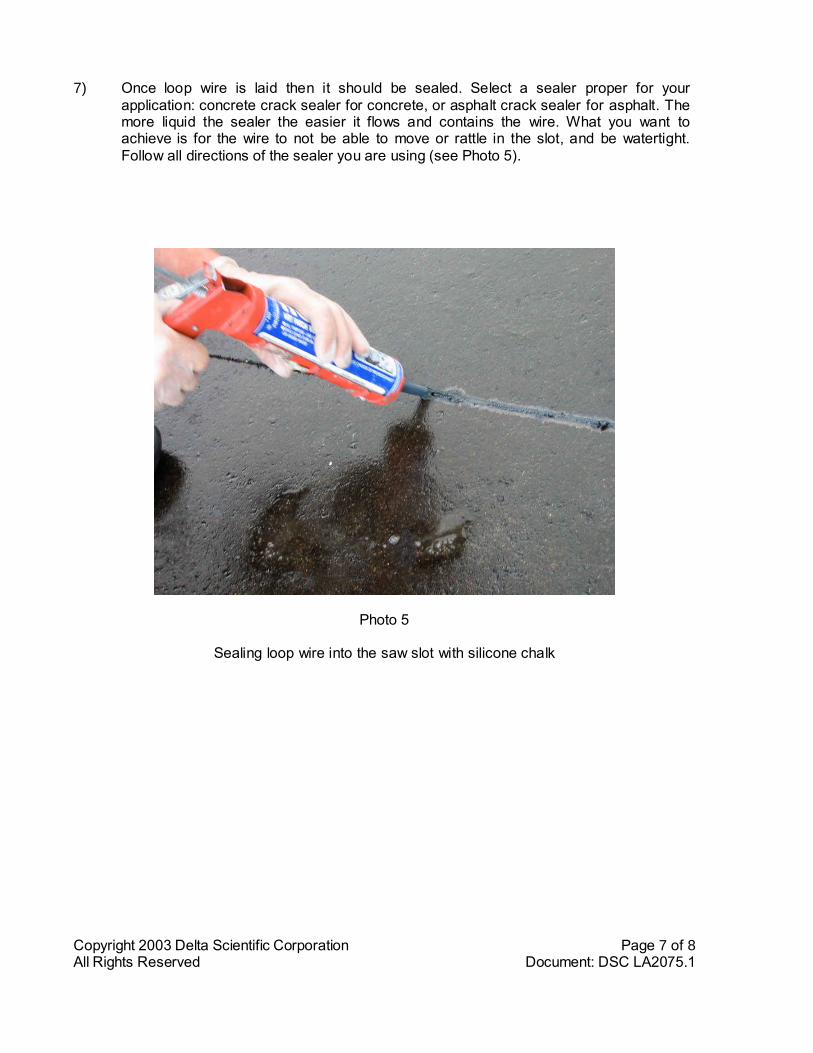
Copyright 2003 Delta Scientific Corporation Page 7 of 8All Rights Reserved Document: DSC LA2075.1
7) Once loop wire is laid then it should be sealed. Select a sealer proper for yourapplication: concrete crack sealer for concrete, or asphalt crack sealer for asphalt. Themore liquid the sealer the easier it flows and contains the wire. What you want toachieve is for the wire to not be able to move or rattle in the slot, and be watertight.Follow all directions of the sealer you are using (see Photo 5).
Photo 5
Sealing loop wire into the saw slot with silicone chalk
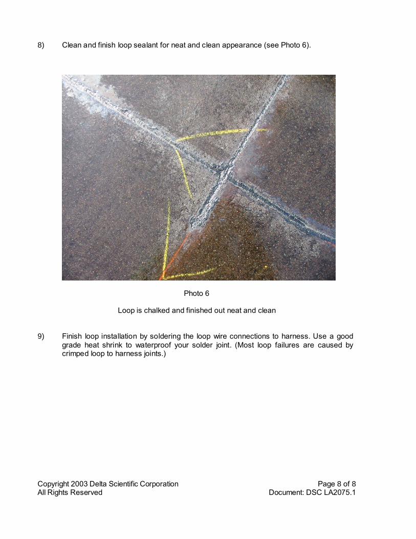
Copyright 2003 Delta Scientific Corporation Page 8 of 8All Rights Reserved Document: DSC LA2075.1
8) Clean and finish loop sealant for neat and clean appearance (see Photo 6).
Photo 6
Loop is chalked and finished out neat and clean
9) Finish loop installation by soldering the loop wire connections to harness. Use a goodgrade heat shrink to waterproof your solder joint. (Most loop failures are caused bycrimped loop to harness joints.)
