instruction manual r20 fifth wheel hitch 30867 · you can take it with you. instruction manual r20...
TRANSCRIPT
You can take it with you.
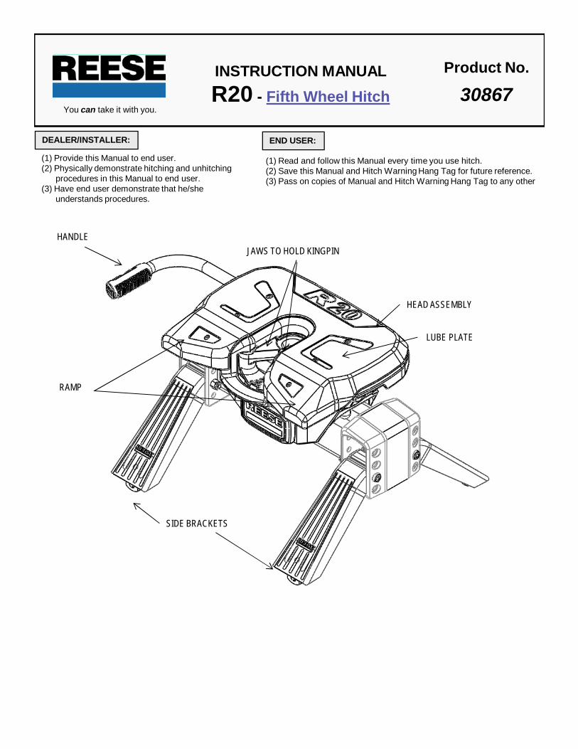
INSTRUCTION MANUALR20 - Fifth Wheel Hitch
Product No.
30867
(1) Provide this Manual to end user.(2) Physically demonstrate hitching and unhitching
procedures in this Manual to end user.(3) Have end user demonstrate that he/she
understands procedures.
DEALER/INSTALLER: END USER:
(1) Read and follow this Manual every time you use hitch. (2) Save this Manual and Hitch Warning Hang Tag for future reference.(3) Pass on copies of Manual and Hitch Warning Hang Tag to any other
HEAD ASSEMBLY
HANDLE
SIDE BRACKETS
RAMP
JAWS TO HOLD KINGPIN
LUBE PLATE

FACTORY TRAILER + FULL WATER TANKS + CARGO, ETC.= GROSS TRAILER WEIGHT
Fig. 1
15-25%GROSS TRAILER
WEIGHT(PIN WEIGHT)
75-85%GROSS TRAILER
WEIGHT
Fig. 2
GROSS TRAILER WEIGHT
GUIDELINES FOR MATCHING HITCH TRUCK AND TRAILER
WARNING:Failure to follow these instructions may result in death or serious injury!
WARNING:Trailer and its contents together must not exceed truck, hitch and/or trailer tow ratings.Towing vehicle must have a manufacturer’s rated towing capacity equal to or greater than the gross trailerweight (dry weight of the trailer plus payload of the trailer). (See Fig. 1)Gross weight of trailer must not exceed 20,000 pounds.King pin weight must not exceed 5,000 pounds (See Fig. 2). If in doubt have king pin weight measured byqualified facility.
1. Reese hitches are designed for use with recreational fifth wheel trailers only. Hitch applications other than recreational fifthwheel trailers must be approved in writing by Reese’s Engineering Department.
2. Use only a SAE 2-inch king pin with your Reese Fifth Wheel Hitch.3. Approximately 15%-25% of trailer weight should be on hitch (Pin Weight). See Fig 2.
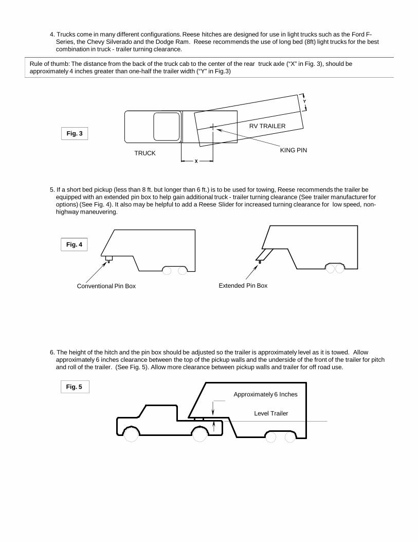
4. Trucks come in many different configurations. Reese hitches are designed for use in light trucks such as the Ford F-Series, the Chevy Silverado and the Dodge Ram. Reese recommends the use of long bed (8ft) light trucks for the bestcombination in truck - trailer turning clearance.
5. If a short bed pickup (less than 8 ft. but longer than 6 ft.) is to be used for towing, Reese recommends the trailer beequipped with an extended pin box to help gain additional truck - trailer turning clearance (See trailer manufacturer foroptions) (See Fig. 4). It also may be helpful to add a Reese Slider for increased turning clearance for low speed, non-highway maneuvering.
6. The height of the hitch and the pin box should be adjusted so the trailer is approximately level as it is towed. Allowapproximately 6 inches clearance between the top of the pickup walls and the underside of the front of the trailer for pitchand roll of the trailer. (See Fig. 5). Allow more clearance between pickup walls and trailer for off road use.
KING PIN
RV TRAILER
TRUCK
Fig. 3
Conventional Pin Box Extended Pin Box
Fig. 4
Rule of thumb: The distance from the back of the truck cab to the center of the rear truck axle (“X” in Fig. 3), should be approximately 4 inches greater than one-half the trailer width (“Y” in Fig.3)
Approximately 6 Inches
Level Trailer
Fig. 5

ASSEMBLY INSTRUCTIONS
WARNING:•Connection for trailer wiring should be in the side of the truck bed between the driver’sseat and the wheel well for the back truck axle•Installation of connection rearward of the wheel well may result in user placing bodybetween truck and trailer. WHENEVER POSSIBLE, AVOID PUTTING BODY UNDER TRAILER OR BETWEEN TRUCK AND TRAILER!•If you need to place any part of your body under trailer or between truck and trailer:
All trailer tires MUST be blocked in front and behind each tire AND Trailer landing gear MUST be resting on firm ground AND Truck MUST be stationary, in park, with emergency brake on!
WARNINGBase rails must be bolted through the floor of the pickup to the brackets that attach to the truck frame. DO NOT INSTALL BY FASTENING TO THE FLOOR OF THE PICKUP BOX ONLY. The floor alone is not strong enough to carry the loads imposed by the trailer.
Fig. 7
BASERAILS
WARNING:DO NOT use this hitch for towing a trailer with a pin box that could come in contact with or interfere with the latch of the hitch handle when turning! (See Fig 6) If the pin box contacts the hitch handle or its latch when turning, the trailer may become unhitched.
HANDLEKING PIN
BOTTOM OF PIN BOX
Fig. 6
1. Reference Fig. 20 on back page. Number in parentheses refer to parts in Fig. 20.2. R16 Fifth Wheel is contained in two cartons. Unpack and become familiar with parts on parts list. Base rail, brackets and
hardware are in separate kits (Part no’s. 30035, or 30095 or 30153) with separate installation instructions for Fifth Wheel RailMounting Kit.
3. Place two base rails across bed of truck (See Fig 7). Select one leg and place tabs through the middle rectangular slot in thebase rails. Slip long pull pins through holes in base rails from the inside out as shown so the cotter pins are on the outside ofthe base rails. Repeat for other leg. Secure pull pins with the spring retaining pins .
4. Select cross member (8) and install on leg aligning holes for hitch height desired. (Lowest position 14” highest 18”). Install four½-13x4.5” Socket Head Cap bolts (9), with the heads towards the outside as shown, and lock nuts (10).
5. Torque ½” nuts to 75 lb.ft.6. Install base rails and mounting brackets as described in “Installation Instructions for 5th Wheel Rail Mounting Kit.”

IMPORTANT: YOU ARE RESPONSIBLE FOR SAFE HITCHING AND UNHITCHING OPERATIONS. DO NOT RELY ON OTHERS TO PERFORM YOUR DUTIES. YOU MUST PERSONALLY MAKE SURE THE FOLLOWING STEPS ARE PERFORMED IN THE FOLLOWING ORDER!
WARNING:FAILURE TO FOLLOW THESE INSTRUCTIONS MAY RESULT IN DEATH OR SERIOUS INJURY.
BEFORE EACH TRIP:
HITCHING PROCEDURE:
Fig. 8CORRECT
Skid Plate Ramp (C)
Hitch Skid Plate (B)
Bottom of Pin Box (A) Bottom of Pin Box Above
Hitch Skid Plate
Fig. 9WRONG
WARNING:Failure to follow this instruction may result in king pin being too high and coming to rest on top of closed jaws or not completely inside jaws. (See Fig. 9). This could result in trailer separating from hitch. Trailer separation may result in death or serious injury if anyone is under the trailer or between truck and trailer when separation occurs.
Bottom of Pin Box (A) 1/2 To 1 Inch Below Hitch Skid Plate (B)
1. A plastic lube plate is supplied with the R20 (see figure on cover of Manual). Do not use automotive type chassis grease toprovide the lubricated surface.
2. DO NOT USE A ROUND LUBE PLATE WITH THE R20. A PLASTIC LUBE PLATE IS STANDARD EQUIPMENT ON THER20.
3. Before each trip or maneuver, operate the handle and check that the jaws open and close freely.4. See that all hitch pins (#16 on Fig.20) are in place and the spring retaining pins (#17 on Fig.20) are installed.
1. Place blocks (sometimes called “chocks”) firmly against front and rear if each trailer wheel to prevent any possible forward orrearward motion. DO NOT REMOVE BLOCKS UNTIL EACH OF THE FOLLOWING STEPS AND THE PULL TEST HAVEBEEN COMPLETED. Lower tailgate if necessary.
2. Using trailer jacks, adjust trailer height following the directions in the trailer manual so that bottom of trailer pin (“A” in Fig. 6) is½ to 1 inch below skid plate (See “B” in Fig. 8). During the hitching maneuver, the bottom of the trailer pin box should come incontact with the skid plate ramp (“C” in Fig. 8).

Fig. 10b
King pin
3. Rotate hitch handle from locked position (see Fig. 10a) up to the unlocked position (See Fig 10b). This will unlock the jawsystem. NOTE: Hitch jaws will not open and proper hitching cannot occur if handle is NOT pointed up.
LOCKED
UNLOCKED
King pin
King pin
King pin Indicator – Out kingpin is Locked in position
Fig. 11 Fig. 12
Fig. 13
4. With handle in the unlocked position (See Fig. 10b), back truck slowly into trailer. As the trailer king pin enters the hitch it willpush the hitch jaws open and extend the handle (See Fig. 12). As king pin completely enters head, jaws will spring closedaround king pin and handle will return to the closed position and king pin indicator will extend out from the head assembly (SeeFig. 13).
5. After king pin is latched rotate handle down to ensure jaws are locked around king pin (See Fig. 14).6. Use only the method described above for hitching.
Fig. 14
Fig. 10a
WARNING:Do not attempt to hitch by using trailer jacks to lower trailer and king pin. This could result in king pin coming to rest on top of skid plate instead of within hitch opening where jaws are located. King pin could slide off hitch and trailer could drop, resulting in death or serious injury.

Fig. 16WRONG
Fig. 15CORRECT
High PinNo Space
KING PIN JAWS CLOSED
HANDLE IN LOCKED POSITION
Fig. 17b
7. With all trailer wheels still firmly blocked, landing gear still resting on firm ground and supporting trailer weight, and truckstationary and in park with the emergency brake on: visually check that bottom of pin box is resting on top of the hitch. THERESHOULD BE NO SPACE BETWEEN THESE SURFACES (See Fig 15). If space exists, (See Fig 16) trailer has not beenproperly hitched. DO NOT TOW! Instead, repeat above steps until trailer is properly hitched. DO NOT PLACE BODY UNDERTRAILER TO PERFORM THIS INSPECTION!
8. To ensure that the jaws are locked and closed, the handle must be rotated in the down position (See Fig 17a). IF HANDLEDOES NOT ROTATE DOWN, THE TRAILER HAS NOT BEEN PROPERLY CONNECTED TO HITCH. DO NOT TOW!Repeat above steps until trailer is properly hitched. (See Fig 17b)
Fig. 17a
9. With:• All trailer wheels still firmly blocked in front and behind each tire, and• Truck stationary with the emergency brake on, and• Trailer landing gear still resting on firm ground and supporting trailer weight, and• Truck stationary and with emergency brake on:
10. Connect electrical cable between truck and trailer, connect breakaway switch cable from pin box to a permanent part of truck,and raise tailgate of truck.
WARNING•WHENEVER POSSIBLE, AVOID PUTTING BODY UNDER TRAILAER OR BETWEEN TRUCK AND TRAILER.
•If you need to place any part of your body under trailer or between truck and trailer:•All trailer tires MUST be blocked in front and behind each tire AND•Trailer landing gear MUST be resting on firm ground AND•Truck MUST be stationary, in park, with emergency brake on!

1. With :• All trailer wheels still firmly blocked, and• Trailer landing gear still resting on firm ground and supporting trailer weight, and• Truck stationary and with the emergency brake on:• Return to cab of truck and release truck’s emergency brake. Apply trailer brakes. After making sure no one is
between truck and trailer, try to pull trailer slowly forward with the truck. If the trailer is properly hitched, the wheelblocks and trailer brakes should keep the truck from moving forward.
NOTE: If trailer is not properly hitched, trailer will separate from hitch and truck will move forward leaving trailer behind. If the trailer landing gear is still resting on firm ground supporting the trailer weight and wheel blocked, trailer will not be able to drop or fall.
2. After successfully performing above steps, fully raise trailer landing gear (see trailer manual).3. Check and inspect all electrical circuits for proper operation. (Clearance lights, turn signals, stop lights, etc.).4. Remove and store all trailer wheel blocks.
PULL TEST
WARNING:Failure to perform this test may result in death or serious injury!
WARNING:Failure to keep wheels blocked and landing gear down could result in trailer suddenly moving or falling. This could result in death or serious injury!
UNHITCHING PROCEDURE:
PERFORM THE FOLLOWING IN THIS ORDER:1. Place blocks firmly against front and rear of each trailer wheel to prevent any possible forward or rearward motion.2. Using trailer jacks, lower trailer landing gear following the directions in the Trailer Manual until feet of landing gear are resting
on firm ground.3. Make sure truck is in park with the emergency brake on.
4. Lower truck tail gate.5. Disconnect power cable and breakaway switch cable between truck and trailer.6. Rotate hitch handle up to the unlocked position (See Fig 18) and pull the handle towards you so that the king pin is no longer
securely grasped by hitch jaws (See Fig 19 ). Trailer is now free from hitch and truck. If handle does not pull out, there isprobably pressure against the jaws. To relieve this pressure, back the truck slightly. Reset truck emergency brake. Then pullhitch handle out completely.
WARNING:Trailers that are not stable or properly hitched can fall and kill you! To avoid death or serious injury:
•All trailer tires MUST be blocked in front and behind each tire AND•Trailer landing gear MUST be resting on firm ground AND•Truck MUST be stationary, in park, with emergency brake on!
Fig. 18 Fig. 19

7. AFTER MAKING CERTAIN NO ONE IS STANDING BETWEEN TRUCK AND TRAILER OR IN FRONT OF TRUCK, drive truckslowly away from trailer.
8. Close hitch jaws by pushing handle forward and rotating down.9. KEEP WHEEL BLOCKS IN PLACE. This will keep trailer from moving unexpectedly
WARNINGWhenever possible, avoid putting body under trailer or between truck and trailer. If you need to place any part of your body under trailer or between truck and trailer:
•All trailer tires MUST be blocked in front and behind each tire AND•Trailer landing gear MUST be resting on firm ground AND•Truck MUST be stationary, in park, with emergency brake on!

1
14
2
3
5 4
5
67
8
9
107
17
12
17
11
13
15
4
16
ITEM NO DESCRIPTION PCS1 HANDLE GRIP (1)2 LUBE PLATE (1)3 HEAD PAN ASSEMBLY (1)4 HEAD PIN (2)5 KLIK PIN (3)6 1 1/4" CASTLE NUT (1)7 SURGE ISOLATOR (2)8 CROSS MEMBER (1)9 1/2"-13 X 4.5" SOCKET HEAD CAP SCREW (4)
ITEM NO DESCRIPTION PCS10 1/2" LOCK NUT (4)11 SIDE BRACKETS (2)12 PIVOT PIN (1)13 PIVOT BEAM (1)14 1/4"-20 SOCKET HEAD CAP SCREW (6)15 HEAD ISOLATOR (2)16 PULL PIN (4)17 RETAINING CLIPS (4)
FIGURE 20
(OVER)
.
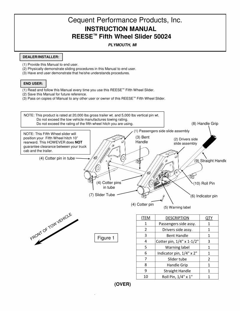
(1) Passengers side slide assembly
(2) Drivers side slide assembly
(5) Warning label
(6) Indicator pin(7) Slider Tube
(4) Cotter pinsin tube
(4) Cotter pin
(8) Handle Grip
(4) Cotter pin in tube(9) Straight Handle
(10) Roll Pin
PLYMOUTH, MI
Figure 1
(1) Provide this Manual to end user.(2) Physically demonstrate sliding procedures in this Manual to end user.(3) Have end user demonstrate that he/she understands procedures.
(1) Read and follow this Manual every time you use this REESE™ Fifth Wheel Slider.(2) Save this Manual for future reference.(3) Pass on copies of Manual to any other user or owner of this REESE™ Fifth Wheel Slider.
DEALER/INSTALLER:
END USER:
INSTRUCTION MANUALREESE™ Fifth Wheel Slider 50024
(3) Bent Handle
Cequent Performance Products, Inc.
NOTE: This product is rated at 20,000 lbs gross trailer wt. and 5,000 lbs vertical pin wt.Do not exceed the tow vehicle manufactures towing rating.Do not exceed the rating of the fifth wheel hitch you are using.
NOTE: This Fifth Wheel slider will position your Fifth Wheel hitch 10” rearward. This HOWEVER does NOTguarantee clearance between your truck cab and the trailer.
ITEM DESCRIPTION QTY
1 Passengers side assy. 1
2 Drivers side assy. 1
3 Bent Handle 1
4 Cotter pin, 1/4" x 1-1/2" 3
5 Warning label 1
6 Indicator pin, 1/4" x 2" 1
7 Slider tube 2
8 Handle Grip 1
9 Straight Handle 1
10 Roll Pin, 1/4" x 1" 1

1. Fifth wheel trailers are typically designed for use with long bed (8 foot) trucks. These trucks provide ample turningclearance between the truck cab and trailer front (recommended).
2. Short bed trucks (less than 8 ft.) require additional turning clearance to avoid truck cab or trailer damage duringnormal turns. This is best accomplished through the use of a trailer pin box extension (see Figure 2). CequentPerformance Products, Inc. suggest the use of a minimum of a 13 inch pin box extension to be able to comfortablymake normal turning maneuvers with a short bed truck. Contact your trailer manufacturer or CequentPerformance Products, Inc. for pin box extension options.
3. The REESE™ FIFTH WHEEL SLIDER is designed to be used with Cequent Performance Products, Inc. FifthWHEEL installations only. These installations are described in the Cequent Performance Products, Inc.INSTALLATION INSTRUCTIONS BASE RAIL MOUNTING KITS. These instructions specify the exact placementof the base rails in relation to the rear of the truck bed for most current pickup trucks. See your REESE™ dealer forother installation instructions.
WARNING:Failure to follow these instructions may result in death or serious injury!
BEFORE INSTALLATION
Figure 2 Trailer Pin Box ExtensionConventional Pin Box
CAUTION:Turning clearance is reduced when towing with a short bed truck! This can result in
the trailer striking the inside of the truck bed. Always monitor the truck cab and the trailer clearance during turns. Failure to do so could result in significant property damage.
WARNING:Slide hitches that are not properly locked can suddenly move and kill you!
To avoid death or serious injury:•Never place any part of your body in the truck bed or between the truck and the trailerunless each and every one of the following conditions are met :
1. Truck is in park with emergency brake on, and2. All trailer wheels are blocked on each side of wheel.
•Always perform “push test” or “pull test” by following the instructions in this manual.
WARNING:Never tow trailers on the highway or at high speed conditions with SLIDER in the Maneuvering Position (rearward of the rear axle)! Towing with the trailer king pin rearward of the rear truck axle can affect weight distribution and may interfere with the towing vehicle’s handling and response characteristics. Poor handling and response characteristics could result in death or serious injury.

In this figure, the REESE™ FIFTH Wheel Slider is positioned in the Towing Position. Note that a 13-1/2" pin box extension has been used. This is the only position you should use when towing!
In this figure, the REESE™ FIFTH Wheel Slider is positioned in the Maneuvering Position. Note that a 13-1/2" pin box extension has been used. The maneuvering Position should only be used at a low speed, when high maneuverability is needed!
5. Due to the heavy duty nature of the REESE™ FIFTH WHEEL SLIDER assembly, the assembly may notslide by hand when installed, especially if base rails are not parallel and centered. Rails should be installed sothat the center lines of each rail are (21 15/16”) apart (see Figure 6). Diagonal dimensions "x" and "y” (asdepicted in Figure 6) should be within 0.1 inch (1/8”) of each other.If this alignment is not met, loosen hardware and realign base rails. Re-torque hardware perbase rail instructions after base rails are properly aligned.
4. The REESE™ FIFTH WHEEL SLIDER provides additional turning clearance for low speed, off-highwaymaneuvering such as backing a fifth wheel trailer into a tight camp site. This is done by sliding the hitch 10 inches rearward of its normal Towing Position (Figure 3) to a Maneuvering Position (Figure 4). This places the trailer king pin behind the rear truck axle.
WARNING:Never tow trailers on the highway or at high speed conditions with the SLIDER in the Maneuvering Position (rearward of the rear axle)! Towing with the trailer king pin rearward of the rear truck axle can affect weight distribution and may interfere with the towing vehicle’s handling and response characteristics. Poor handling and response characteristics could result in death or serious injury.
Figure 6
Base rails in truck bed, refer to instruction manual.
X Y
Figure 3
Rear Axle Rear Axle
Figure 4
KING PIN CENTER
KING PIN
CENTER
(21-15/16”)

3. Before setting the REESE™ FIFTH Wheel Sliderinto the bed of the pickup. Insert the benthandle(3) through drivers side assembly(2)(driver’s side of towing vehicle) and thenthrough passengers side slide assembly(1). Slidestraight handle(9) over bent handle(3). Install rollpin(10). See Figure 8.
Hint: It may be easier to lay the handles on a firm surface to install the roll pin. Then insert the handle into the drivers and passengers assemblies.
When installing handle grip (8), rotate it so the molded finger areas align for your use. Either left hand or right hand usage.
4. Set the REESE™ FIFTH Wheel Slider intobase rails and pin in position as shown inFigure 9 below.
Figure 9
Figure 8
2. Before installing REESE™ FIFTH Wheel Slider,the leaf spring must be greased as shown usingwhite lithium grease or equivalent (see Figure 7). Forbest results, use aerosol white lithium grease with aspray nozzle extension. Make sure entireunderside of spring is coated! Repeat this applicationmonthly during use.
Safety label facing driver side.
1. These instructions should be used to mount the REESE™ FIFTH Wheel Slider. Care and attention to detail willensure a quick, safe and quality installation. Check parts against Figure 1 to become familiar with kit.
INSTALLATION
WARNING:Pull pin spring clips must
be on the outside of base rail as shown. (Spring clips installed on the inside of
base rail will not allow Slider to move far enough to lock). Sliders that are not properly locked can suddenly move and cause serious injury or
death.
Slide TubeSlide Upright
Aerosol white lithium grease spray with nozzle
extension
Leaf spring
Figure 7
BASE RAIL
(10)

5. Loosely assemble head support to REESE™ FIFTH Wheel Slider at desired height.NOTE: Bottom position may not be used on all hitch models.Use the cotter pins(4) and indicator pin(6) to trap handle(3) inplace as shown. Be sure pin is installed in handle as shown. Install so thatthe indicator pin is in both slots of the casting. (See Figure 11).
Figure 13
7. Coat top surface of slide tube and roller holes in eachslider assembly with all purpose grease or Teflon lube, use as needed (see Figure 12). Repeat this application monthly during use. Figure 12
Figure 10
6. Snug up all bolts and nuts.Torque 1/2” bolts to 85 ft. lb.
Cotter pin (4).On back inside.
Indicator pin (6)
ROLLERSLIDE TUBE
LOCK WASHER & BOLT
END CAPS
LEAF SPRING
LATCH
WELD-ON FOOTBOLT-ON FOOT
Indicator pin (6) in both slots of the latch casting.
Figure 11
Cotter pin (4)On back side
ROLLER HOLES
SLIDE TUBE
WARNING:Slide hitches that are not properly locked can suddenly move and kill you!
To avoid death or serious injury:•Never place any part of your body in the truck bed or between the truck and the trailerunless each and every one of the following conditions are met :
1. Truck is in park with emergency brake on, and2. All trailer wheels are blocked on each side of wheel.
•Always perform “push test” or “pull test” by following the instructions in this manual.
(3)
FRONT OF TOW VEHICLE

Leaf spring on latch cam and lock pin keeps latch from disengaging. Hitch can not move rearward with lock pin and latch engaged.
FRONT OF TOW VEHICLETOWING POSITION
Figure 14
1. Position truck and trailer in a straight line on a flat, level area.2. Place truck in “Park” with emergency brake “on”.3. Remove lock pin from towing hole and pull handle (9) forward (see Figure
15). If handle (9) is hard to move it may be wedged into the latching holein the slider tube (7). This can be remedied by slightly moving the truckback or forth until the handle (9) moves freely. Repeat step 2 if needed.
4. Indicator pin (6) should be over the red unlocked range, near thegreen maneuvering range (see Figure 15). Springpressure will press latch against top of tube.
5. Return to truck. Release emergency brake. Manually engagetrailer brake and pull truck forward until REESE™ FIFTH WheelSlider stops and the latches engage in maneuvering position(see Figure 16).
MOVE TO MANEUVERING POSITION
Figure 15
6. Perform “PUSH TEST” as follows:A. Manually engage trailer brakes from truck cab.B. Back truck into trailer.C. If Slider does not move, latch has engaged tubes (7)
and Slider should be engaged in maneuvering position.D. If Slider does move, latch has not engaged tubes (7).
DO NOT TOW!! Repeat steps 1 - 6 above until the latch has engaged the tubes (7).
E. Install lock pin completely in maneuvering hole. (See figure 16)7. Examine warning label (5). Indicator pin (6) should now be over the green range
on the left side of the warning label (5) (see Figure 16).
MOVE FROM TOWING TO MANEUVERING POSITION
MANEUVERING POSITION
Figure 16
Indicator pin (6)
Indicator pin (6)
Indicator pin (6)
FRONT OF TOW VEHICLE
WARNING:Slide hitches that are not properly locked can suddenly move and kill you!
To avoid death or serious injury:•Never place any part of your body in the truck bed or between the truck and the trailerunless each and every one of the following conditions are met :
1. Truck is in park with emergency brake on, and2. All trailer wheels are blocked on each side of wheel.
•Always perform “push test” or “pull test” by following the instructions in this manual.
Lock pin
Bolt-on foot
lock pin
(9)
(7)
(5)
(9)
(7)
See Note
Note: Keep areas around the feet and latching holes clear for proper operation.
Caution: Make sure truck tailgate has clearance prior to sliding the hitch back.

MOVE FROM MANEUVERING TO TOWING POSITION
1. Position truck and trailer in a straight line on a flat, level area.2. Place truck in “Park” with emergency brake “on”.3. Remove lock pin from maneuvering hole and push handle (9) rearward (see
Figure 17). If handle (9) is hard to move itmay be wedged into the latching hole in the slider tube (7). This can beremedied by slightly moving the truck back or forth until thehandle (9) moves freely. Repeat step 2 if needed.
4. Indicator pin (6) should be over the red unlocked range near thegreen towing range (see Figure 17).Spring pressure willpress latch against top of tube.
Caution: Make sure truck tailgate has clearance prior to sliding the hitch forward.5. Return to truck. Release emergency brake. Manually engage
trailer brake and back truck rearward until REESE™ FIFTH WheelSlider stops near the bolt on foot (Figure 12) and the latch engagesin the towing position (see Figure 18).
6. Perform “PULL TEST” as follows:A. Manually engage trailer brakes from truck cab. Pull truck ahead.B. If Slider does not move, the latch has engaged the tubes (7)
and Slider should be engaged in the towing position.C. If Slider does move, the latch has not engaged the tubes (7).
DO NOT TOW!. Repeat steps 1 - 6 above until the latch has engaged the tube (7).
D. Install lock pin completely in towing hole. (see figure 18)7. Examine the warning label (5). Indicator pin (6) should now be over the
green range on the right side of the warning label (5) (see Figure 18). If the indicator (6) pin is over the red range on the warning label (5), the latch has not the engaged the tubes (7). DO NOT TOW! Repeat steps 1- 6 above.
MOVE TO TOWING POSITION
FRONT OF TOW VEHICLE
Figure 17
TOWING POSITION
Indicator pin (6)
Figure 18
Indicator pin (6)
FRONT OF TOW VEHICLE
WARNING:Slide hitches that are not properly locked can suddenly move and kill you!
To avoid death or serious injury:•Never place any part of your body in the truck bed or between the truck and the trailer unless eachand every one of the following conditions are met :
1. Truck is in park with emergency brake on, and2. All trailer wheels are blocked on each side of wheel.
•Always perform “push test” or “pull test” by following the instructions in this manual.
lock pin
(9)
(5)
(7)