instruction manual - sanki-web.co.jp · instruction manual high-function type p212-f p312-f this...
TRANSCRIPT

PIEZO FEEDER CONTROLLER
Instruction Manual
High-Function Type
P212-F
P312-F
This Instruction Manual is applicable to
Piezo Feeder Controller version 1 and later.
Confirm the version information displayed
upon powering ON.
Read the Manual carefully beforehand to ensure the safe use of the Controller.
After reading, store the Manual within reach so as to be ready for rereading.
The dealer is requested to be sure to deliver the Manual to the end user.
1

Contents
1. Introduction
2. Before Using
3. Precautions for Safety
4. Name of Each Part
5. Connection of Inputs and Outputs
6. Explanation of Operation Panel
7. Displayed Mode
8. First-Time Use
9. Default Setting
10. Adjusting Amplitude
11. Added Function
12. Parameters
13. Guard and Alert
14. Troubleshooting
15. Options
16. Specifications
17. Outside Dimensional Drawing
18. Warranty
2

1. Introduction
Thank you for your selection of our Piezo Feeder Controller, a digital controller for piezo
feeder (“Controller”).
The piezo feeder is a high-efficiency, energy-saving parts feeder driven by piezoelectric
elements.
In combination with the dedicated digital controller, the Controller can be operated easily
and efficiently without requiring any difficult adjustment. Before connecting the piezo feeder
and performing subsequent adjustment, read the Manual carefully to ensure proper use of
the excellent functions of the piezoelectric parts feeder.
2. Before Using
Before unpacking, be careful not to have an impact or vibration on the packing.
Unpack, and check the following:
(1) Isn’t there any damage caused during transport?
(2) Are the rating, capacity and model on the nameplate exactly what you have ordered?
If there is any problem, contact the dealer.
3. Precautions for Safety
Be sure to read the Manual carefully before the installation, operation, maintenance,
checkup, etc. of the Controller to ensure your familiarity with the Controller, safety
information and precautions.
In the Manual, the safety precautions are divided into “DANGER” and “CAUTION” according
to their severities.
DANGERIf the Controller is handled improperly, a dangerous situation could
be caused, and the possibility of death or injury is assumed.
CAUTION
If the Controller is handled improperly, a dangerous situation could
be caused, and the possibility of medium or minor injury or partial
damage is assumed.
3

DANGER
・ Do not service the Controller in the Power-ON status. To avoid an electric shock, be
sure to turn OFF the power supply before starting the service.
・ Do not disassemble, remodel or repair the Controller, or an electric shock, a fire or
injury could be caused. For repair, ask the dealer.
・ Do not remove the front cover while the Controller is in the Power-ON status, or an
electric shock could be caused.
・ Do not put or insert anything in or into the Controller, or an electric shock or a fire
could be caused.
・ Do not use the Controller near explosive or flammable gas, or a fire could be caused.
・ Do not splash water or liquid, or an electric shock or a fire could be caused.
・ If smoke, odor or abnormal noise is emitted or other abnormality is detected, shut
down the Controller immediately. If the Controller is used in the abnormal status, a
fire could be caused. Contact the dealer.
・ If the Controller is not operated for a long time, shut down the Controller. If the
Controller is left live as it is, a fire could be caused.
・ Connect the power cable and the output cable as instructed in the Manual to avoid
an electric shock and a fire.
・ Do not forcedly bend, pull or pinch the power cable or the output cable, or an electric
shock or a fire could be caused.
・ Ground the earth terminal and the ground prescribed portions without fail, or an
electric shock could be caused. When working on grounding to a high position or a
shaky stand, because fall or tumble could be caused conditionally, take measures to
prevent fall or tumble.
・ Do not conduct megger testing for any terminals other than the input terminal.
CAUTION
・Do not use the Controller for an electromagnetic parts feeder or the like.
・Do not turn ON/OFF the power supply frequently, or failure could be caused.
・ Do not start/stop the vibrator with an electromagnetic contactor or the like on the
output side, or failure could be caused.
・Do not perform welding work on the vibrator side in the Power-ON status.
・ Do not perform welding work on the vibrator side when the vibrator and the Controller
are in the connected status.
・Do not remove the nameplate, the seal, or the like.
・When installing the Controller, hold and fix it firmly and properly.
・ Do not transport or carry the Controller in the piled-up status, even in the packed
status, or they could fall, causing injury.
・ Do not place the Controller outdoors, in a humid place or in a place with excessive
temperature change.
・Do not pile up the Controller two-tired or more, even in the packed status.
・When disposing of the Controller, dispose it properly as general industrial waste.
4

4. Name of each unit
Operation panel removed status
When attaching/detaching
the operation panel, carefully
watch out for disconnection,
pinching, etc.
Operation panel
Operation panelOperation panel
connecting wire
External control
terminal block (S)
Vibration
sensor
connector
Relay output
terminal block (B)
Relay connector
Rubber bush
Operation panel fixing screw
(2 locations)
Overflow sensor input cable
(P3 cord)
External control
terminal block (A) for
added function
Output cable
Vibration sensor input cable
(P4 cord)
[accessory]
Power cable
in2 Input
selector
5

Terminal block No.
Wiring to the external signal terminal block (screw-less)
While holding down the button on the terminal block with a
flat-blade screwdriver or the like, insert the wire into the wire
insertion hole. Then, detach the flat-blade screwdriver to
release the button, and the wire will be fixed.
Applicable wire size
・Terminal block (A), (S)
Stranded wire: 0.08 – 0.32mm2 (AWG28 – 22), Strand diameter: φ0.12mm or more
Solid wire: φ0.32 – 0.65mm (AWG28 – 22)
・Terminal block (B)
Stranded wire: 0.2 – 0.75mm2 (AWG24 – 20), Strand diameter: φ0.18mm or more
Solid wire: φ0.4 – 1.2mm (AWG26 – 16)
Cover removed length: 9 – 10mm
Board side
connector for
P4 cord
Button Wire insertion
hole
24VDC
6

5. Connection of Inputs and Outputs
1) Connection to the vibrator
Confirm that the power supply is in the OFF status. Then, connect the output cable of the
Controller to the vibrator cable of the piezo feeder.
The connector wire colors should be identified as follows:
※1: Do not connect any vibrator other than the piezo feeder made by Sanki.
※2: Do not operate with no load.
※3: Be sure to ground the vibrator.
2) Connection to the power source
Connect the power cable to the single-phase power source.
Do not turn ON the power supply until the whole wiring work is completed.
※1: Be sure to make a connection to the utility power source.
※2: Be sure to ground the Controller.
3) Connection of the overflow sensor
Connect the overflow sensor to the terminal of the overflow sensor input cable (P3 cord).
Piezo feeder
Vibrator cable
100-230VAC
Vibration
sensor
(option)
Red [24V terminal No. A0] – Sensor brown wire
White [Signal terminal No. A6] – Sensor black wire
Black [0V terminal No. A3] – Sensor blue wire
Overflow sensor
Black
White
7

※1 The overflow sensor input cable (P3 cord) is connected to the internal terminal block
[in2 Input]. Details ⇒ P. 18.
※2 If the overflow sensor is not used, set to “Parameter No. 07 = Lo.”
4) Connection of the vibration sensor
When conducting the constant-amplitude control, firmly connect the vibration sensor
input cable (P4 cord) (accessory) to the connector on the board for connection to the
vibration sensor (KS-3).
Firmly fix the vibration sensor to the vibrator.
※ To connect the vibration sensor input cable, the operation panel has to be detached.
Confirm the power-OFF status, and then detach the operation panel.
Note that the operation panel is connected to the Controller main body with a
connecting wire. When attaching/detaching the operation panel, carefully watch out for
the connecting wire to avoid disconnection or pinching.
※ Limit the total length of the cable between the Controller and the vibrator (vibration
sensor) to 4m.
To extend the cable, be sure to use the dedicated cable.
In wiring each cable, detach the wiring from the power cable.
5) Connection of the external signal [in1 Input]
Connect the external signal to operate/stop the vibrator in addition to the overflow sensor.
When the external signal is used, set as “Parameter No. 06 = Hi.”
※To connect the external signal, the operation panel should be removed.
Confirm that the power supply is in the OFF status. Then, detach the operation panel.
The operation panel is connected to the main unit of the Controller with a connecting
wire. When attaching/detaching the operation panel, carefully watch out for
disconnection or pinching.
To operate the start/stop of the Controller according to external control signal, either
method of non-voltage contact signal or voltage signal (24VDC) can be used.
Make connection to the external control terminal block by using the method ① or ②below while watching out for the signal to be used and the connection method. When
wiring, be careful not to make mistake about the polarity.
The current of 24VDC and 10mA or less flows between [+S] and [-S]. Carefully select the
connection device (e.g., minute current relay).
8

[Relation between [in1 Input] and [in2 Input]]
①When [in1] is in the operating condition, [in2] is enabled.
② When both [in1] and [in2] are in the operating condition, the vibrator starts operation.
Signal input statusVibrator operation condition
Setting: Hi Setting: Lo
in1 Input
Parameter No. 6
Connection ① :
Close
Connection ② :
24VDC
Operation
conditionStop
Connection ① :
Open
Connection ② :
0VStop
Operation
condition
In2 Input
Parameter No. 7
Sensor signal: ONOperation
conditionStop
Sensor signal: OFF StopOperation
condition
□ : Default
①No-voltage contact signal ②Voltage signal (24VDC)
Example of circuit to be
arranged by customerInternal circuitInternal circuit
Short circuit
No-voltage
contact
9
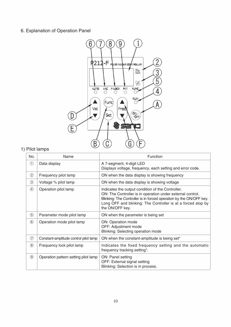
6. Explanation of Operation Panel
1) Pilot lamps
No. Name Function
① Data display A 7-segment, 4-digit LED
Displays voltage, frequency, each setting and error code.
② Frequency pilot lamp ON when the data display is showing frequency
③ Voltage % pilot lamp ON when the data display is showing voltage
④ Operation pilot lamp Indicates the output condition of the Controller.
ON: The Controller is in operation under external control.
Blinking: The Controller is in forced operation by the ON/OFF key.
Long OFF and blinking: The Controller is at a forced stop by
the ON/OFF key.
⑤ Parameter mode pilot lamp ON when the parameter is being set
⑥ Operation mode pilot lamp ON: Operation mode
OFF: Adjustment mode
Blinking: Selecting operation mode
⑦ Constant-amplitude control pilot lamp ON when the constant-amplitude is being set*
⑧ Frequency lock pilot lamp Indicates the fixed frequency setting and the automatic
frequency tracking setting*.
⑨ Operation pattern setting pilot lamp ON: Panel setting
OFF: External signal setting
Blinking: Selection is in process.
10

The lighting status of ⑦ AAC and ⑧ F-LOCK indicating the setting status of the
constant-amplitude control and automatic frequency tracking
Parameter q = on Parameter q = off
F-LOCK = off F-LOCK = on F-LOCK = off F-LOCK = on
Control setting AAC F-LOCK AAC F-LOCK AAC F-LOCK AAC F-LOCK
U0 ○ ○ ○ ● ○ ○ ○ ●U1 ● ●U2 ● ○ ● ● ○ ●
○ : OFF, ● : ON , : Blinking, : ON at a stop, blinking in operation
2) Operation keys
No. Name Description
A ON/OFF key Performs the forced operation and the forced stopping.
B Func key Brief pressing: Selects the function.
Long pressing: Switches the mode between the parameter mode and the
normal mode.
C Set key Brief pressing: Changes and locks the data.
Long pressing: Saves the data (voltage, frequency, each setting).
Starts frequency search, and loads and saves the data.
D Vol UP key Normal mode: Adjusts the output voltage.
When pressed briefly when the frequency is being displayed, the
frequency display switches to the voltage display.
Parameter mode: Selects the parameter No.
E Vol DOWN key
F Freq UP key Normal mode: Adjusts the frequency.
When pressed briefly when the voltage is being displayed, the
voltage display switches to the frequency display.
Functional selection: Changes the settings.
Parameter mode: Changes the parameter data.
G Freq DOWN key
11

7. Display Mode
・ Normal mode: Shows and sets the output voltage or the frequency on the data display
・Parameter mode: Shows and sets the parameter on the data display
When the Func key is pressed long for over 2 sec, the mode switches.
Regardless of the display mode, operation and stopping through the panel and under the
external control is enabled.
1) Setting the function
In the normal mode, when the Func key is pressed when the output voltage or the
frequency is being displayed, each pilot lamp starts blinking in order of
AUTO → FLOCK → PAT → AUTO,
and respective setting items are displayed on the data display.
To select the setting, press the Freq UP/DOWN keys.
To change the setting, press the Set key.
When the setting change is completed, the data display shows the voltage.
If the setting moves to the next item by pressing the Func key without pressing the Set
key when the settings are being changed, the settings are not changed.
※ If the key operation is not tried for over 5 min, the data display shows the voltage.
①AUTO: Selects the operation mode.
The mode is switched in order of n → Srch → tuni → A → n.
Data display Mode Function
A A mode (operation) The vibrator operates according to each operation pattern settings.
This mode is enabled when the constant-amplitude control and the
automatic frequency tracking functions are set.
The voltage and the frequency themselves cannot be changed.
n n mode (adjustment) The vibrator operates with VVVF.
Adjusts the amplitude, and loads and saves the data.
Srch Automatic frequency tuning Searches the resonance frequency.
tuni Tuning Searches for the characteristics of the vibrator at 30% output.
②F-LOCK: Sets the frequency lock
Sets whether the frequency should be locked or not in the n mode.
Set to the operation memory.
③PAT: Switches the operation pattern.
Px (x = 1 – 4): Displays the panel settings (operation pattern loaded to the current
operation memory).
Also loads and saves the operation pattern.
OUTx (x = 1 – 4): Displays the operation pattern of the external signal in3 status.
12

2) Setting the parameter
(1) When the Func key is pressed long for over 2 sec in the normal mode, the FUNC
lamp lights up and the mode switches to the parameter mode.
The data display shows the current parameter set value.
The operation is enabled when the Controller is in either condition, at a stop and in
operation.
(2) Select the parameter to be changed (⇒ P. 21) by pressing the Vol UP/DOWN keys.
(3) When the Set key is pressed, the parameter No. (left 2 digits) starts blinking, and the
set value can now be changed. Change the set value by pressing the Freq UP/DOWN
keys.
(4) When the Set key is pressed, the parameter No. lights up, and the change is saved
temporarily.
(5) When the power supply is turned OFF in this status, the saved contents are cleared.
Save the parameter to the operation pattern to be changed.
(6) Press the Func key long for over 2 sec to switch the mode to the normal mode.
(7) Press the Func key to make the PAT lamp blink.
The operation pattern (Px or OUTx) is displayed on the data display.
(8) Press the Freq UP/DOWN keys to select the operation pattern (Px), and press the
Set key.
(9) “LoAd” is displayed on the data display. Press the Freq UP/DOWN keys to select
“SAVE,” and press the Set key.
(10) “SV 1” is displayed on the data display. Press the Freq UP/DOWN keys to select the
operation pattern to be changed, and press the Set key long for over 2 sec.
“SAVE” is displayed in blinking on the data display, and the mode switches to the
normal mode, and the voltage is displayed.
※ If the key operation is not tried for over 5 min, the mode switches to the normal mode,
and the data display shows the voltage.
13

8. First-Time Use
Flow up to operation start
Input/output connection
・Connect the input and the output, and connect the overflow sensor.
・Connect the vibration sensor, and connect the external I/O signals.
Default setting
Make setting according to the vibrator usage.
・Set the parameter (added function).
Amplitude adjustment
Adjust the amplitude to optimize the work transfer speed.
①Constant-voltage mode (U = 0)
Output the set output voltage and the frequency for a certain length of time.
・Vibration sensor (KS-3) not available
・Set the output voltage and the frequency manually.
②Constant-amplitude mode (U = 2)
Make the amplitude constant by controlling the output voltage.
・Vibration sensor (KS-3) available [Attach the accessory P4 cord.]
・Set the output voltage manually.
・Set the output frequency automatically.
③Constant-amplitude and automatic frequency tracking mode (U = 1)
Make the amplitude constant by controlling the output voltage and the
frequency.
・Vibration sensor (KS-3) available [Attach the accessory P4 cord.]
・Set the output voltage manually.
・Set the output frequency automatically.
・The resonance frequency is tracked automatically.
Added function
・Set the overflow function timer and the speed switching.
Normal operation
14

9. Default Setting
Before powering ON the Controller, recheck the model, specifications and power voltage of
the Controller to confirm no discrepancy, and also recheck the connections to confirm no
wrong connection. Particularly when external signal is used, be careful not to make mistake
about the polarity.
When the Controller is powered ON, the current software version is shown on the display,
then the newest operation pattern as of the powering-OFF time (factory setting when the
Controller is used for the first time) is read to the operation memory, and the Controller
starts operation in the A mode.
1) Setting the adjusting frequency range
Set the frequency range for use in searching for automatic tuning according to your vibrator.
Use the parameter No. 05 for setting.
L: 50 – 180Hz
C: 160 – 280Hz
H: 260 – 400Hz
AL: 50 – 400Hz (factory setting)
2) Setting the control mode
Use the parameter No. xU for setting.
0: Constant-voltage mode (factory setting)
1: Constant-amplitude and the automatic frequency tracking mode
2: Constant-amplitude mode
※ When a multi-speed function is used, set the control mode for all operation patterns to
be used.
3) Setting the vibration sensor
Use the parameter No. xq for setting.
on: Constant-amplitude control using the vibration sensor (factory setting)
off: Constant-amplitude control without using the vibration sensor
The setting is valid when the control mode is the constant-amplitude control mode.
4) Setting the frequency search
Set whether the vibration sensor should be used or not for the automatic frequency tuning.
Use the parameter No. xr for setting.
on: The vibration sensor is used.
off: The vibration sensor is not used (factory setting).
※ When set to off, the automatic frequency tuning is enabled
even in the constant-voltage mode.
Display of factory setting
Display of factory setting
Display of factory setting
Display of factory setting
15
10. Adjusting Amplitude
The following description refers to the factory setting with the external control (in1) not in
use and the overflow sensor input (in2) in the OFF status.
When adjusting, load a small amount of work in the bowl or chute for use only as a guide to
adjustment.
1) Setting the frequency in the constant-voltage mode (U = 0) manually
(1) Power ON the Controller.
Start the Controller in the A mode and normal mode display (output voltage%). (Factory
setting: output voltage% = 0.0%)
(2) Switch the mode to the n mode.
(3) Set the output voltage% by pressing the Vol UP/DOWN keys.
For the first-time adjustment, because the vicinity of the resonance point is searched
for, aim at around 30 – 50% to make it easy to find vibration.
(4) When the ON/OFF key is pressed, the Controller comes into the forced operation,
and starts outputting.
The RUN lamp starts blinking.
(5) Press the Freq UP/DOWN keys to display the frequency, and adjust the frequency to
make the work runs best.
If the vibration becomes excessive due to approach to the resonance point during this
adjustment, lower the output voltage%.
(6) Lower the output voltage% until the vibration reduces in intensity to such an extent
that the work moves slightly when the Vol UP/DOWN keys are pressed, and adjust
the frequency to make the work run best by pressing the Freq UP/DOWN keys.
(7) Now, the frequency adjustment is completed.
Set the output voltage% to the required speed by pressing the Vol UP/DOWN keys.
(8) Lock the set frequency not to be changed by mistake.
When the Func key is pressed, the F-LOCK lamp starts blinking, and the display
shows “off.”
Change “off” to “on” by pressing the Freq UP/DOWN keys, and press the Set key.
The F-LOCK lamp lights up, and the frequency is locked.
(9) If the Controller is powered OFF in this status, the status before adjustment is
resumed. To prevent this, save the adjusted data.
Press the Set key long for over 2 sec. The data display shows “SAVE” in blinking, and
shows the normal mode voltage.
(10) After the completion of the adjustment, switch the mode to the A mode. This is all for
the setting.
※ The above frequency adjustment as described in the steps (5) and (6) can also be used
for the automatic frequency tuning, which will be described in the following section.
16

2) In the constant-amplitude (U = 2) and the constant-amplitude and automatic frequency
tracking (U = 1) mode
(1) Power ON the Controller.
Start the Controller in the A mode and normal mode display (output voltage%). (Factory
setting: output voltage% = 0.0%)
(2) Switch the mode to the n mode.
(3) When the ON/OFF key is pressed, the Controller comes into the forced operation,
and starts output.
The RUN lamp starts blinking.
(4) Press the Func key, and press the Freq UP/DOWN keys to display “tuni” on the data display.
(5) Press the Set key long for over 2 sec to start the tuning.
When the Hz lamp and the % lamp are lighting alternately, it means that the tuning is
in process. Do not touch the bowl or chute. The information of the vibrator is acquired
for use in the constant-amplitude control.
(6) When the alternate lighting of the Hz lamp and % lamp changes to the frequency
display, it means that the tuning is over.
(7) Set the output voltage% by pressing the Vol UP/DOWN keys. For the automatic setting
of the resonance frequency, target the setting of the output voltage to around 30%.
(8) Press the Func key, and press the Freq UP/DOWN keys to display “Srch” on the data display.
(9) Press the Set key long for over 2 sec to start the automatic frequency tuning.
When the Hz lamp and the % lamp are lighting alternately, it means that the automatic
frequency tuning is in process. Do not touch the bowl or chute.
(10) When the alternate lighting of the Hz lamp and % lamp changes to the frequency
display, it means that the tuning is over.
Set the output voltage % to the required speed by pressing the Vol UP/DOWN keys.
If the voltage is changed substantially, repeat the above steps (8) and (9) for adjustment.
(11) Save the adjusted data. Press the Set key long for over 2 sec. The data display
shows “SAVE” in blinking, and shows the normal mode voltage.
Be sure to take this step in the operation status.
(12) Lock the set frequency not to be changed by mistake.
When the Func key is pressed, the F-LOCK lamp stats blinking, and the display shows “off.”
Change “off” to “on” by pressing the Freq UP/DOWN keys, and press the Set key.
The F-LOCK lamp lights up, and the frequency is locked.
When the amplitude is to be adjusted continuously with another operation pattern, do
not perform this operation.
(13) After the completion of the adjustment, switch the mode to the A mode. This is all for
the setting.
※1 If the amplitude adjustment is required again after the operation in the A mode, the set
voltage upon the switching to the n mode is the output voltage at the time of operation.
In the stop status, switch the A mode to n mode again or re-load the operation pattern.
※2 If the amplitude of the vibrator is too small or the output of the vibration sensor is
small, a sensor error may occur. Raise the voltage, and make re-adjustment.
It is advisable to record the final output frequency and output voltage% for the next
maintenance.
17
11. Added Function
The power outlet of the Controller is of 24VDC, 160mA. Watch out for the total consumption
current of the overflow sensor, solenoid valve, etc. to ensure that it will not exceed the
power outlet capacity.
1) Soft start and soft stop functions
If the rising time or falling time of the piezo feeder should be adjusted, change the
settings of the soft start or soft stop.
To change the settings, set the relevant parameter accordingly.
The set time range is 0.2 – 9.9 sec. (Default value: 0.2 sec)
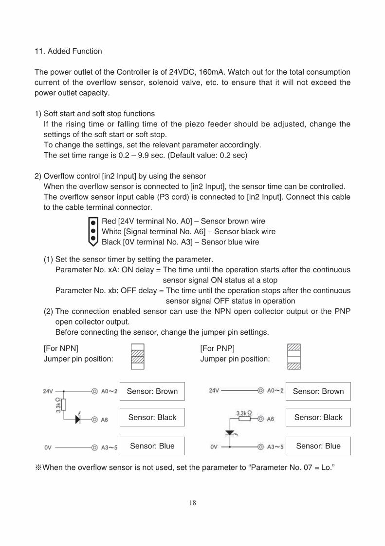
2) Overflow control [in2 Input] by using the sensor
When the overflow sensor is connected to [in2 Input], the sensor time can be controlled.
The overflow sensor input cable (P3 cord) is connected to [in2 Input]. Connect this cable
to the cable terminal connector.
(1) Set the sensor timer by setting the parameter.
Parameter No. xA: ON delay = The time until the operation starts after the continuous
sensor signal ON status at a stop
Parameter No. xb: OFF delay = The time until the operation stops after the continuous
sensor signal OFF status in operation
(2) The connection enabled sensor can use the NPN open collector output or the PNP
open collector output.
Before connecting the sensor, change the jumper pin settings.
※When the overflow sensor is not used, set the parameter to “Parameter No. 07 = Lo.”
Red [24V terminal No. A0] – Sensor brown wire
White [Signal terminal No. A6] – Sensor black wire
Black [0V terminal No. A3] – Sensor blue wire
[For NPN]
Jumper pin position:
[For PNP]
Jumper pin position:
Sensor: Brown Sensor: Brown
Sensor: Black Sensor: Black
Sensor: Blue Sensor: Blue
18

3) External output
(1) Operation signal output out1 [Relay contact output 250VAC, 3A]
Signal synchronous with the vibrator output
(2) Operation signal output out4 [Open collector output 24VDC, 80mA or less]
Signal synchronous with the vibrator output
(3) Operation signal delay output out3 [Open collector output 24VDC, 80mA or less]
According to the timer settings, ON rises up earlier than the vibrator output, and OFF
rises behind the vibrator output.
[Time chart]
※ When [in1 Input] is the operation condition or the forced operation with the ON/OFF
key, the operation is as follows:
Vibrator output
ON delay
Start delay
OFF delay
Stop delay
19

4) Alarm signal, error signal output out2 [Relay contact output 250VAC, 3A]
When the parameter is set to “Parameter No. 08,” the function can be switched to the
work shortage signal and error output.
①AL = Work shortage signal: Outputted if [in2 input] continues for the set time.
②Er = Error signal: Outputted if error stop (e.g., overcurrent error) is caused.
5) Speed switching function
(1) Changing the panel setting operation pattern
①When Px (= 1 – 4) is being displayed, press the Set key to display “LoAd.”
②Press the Set key again to display “Ld 1.”
③Press the Freq UP/DOWN keys to select the operation pattern.
④ Press the Set key long for over 2 sec. The selected operation pattern is loaded, and
the voltage is displayed.
(2) Switching the operation pattern according to the external signal [in3 Input]
①Function setting: Set PAT to [out].
②Select the operation pattern according to the ON/OFF of [in3 Input].
Operation pattern setting
P1 P2 P3 P4
in3 Input OFF ON
[Returning to the factory setting]
(1) When the Controller is in the Power-OFF status, power ON the Controller by pressing the
Vol UP key and the Freq DOWN key together. The Controller starts in the initialization
mode.
(2) Press the Freq UP or Freq Down key to make “99” blink on the data display.
(3) In this status, press the Func key and the Set key together long for over 3 sec. All set
data are reset.
(4) Upon the completion of resetting, the data display shows “99” in lighting.
(5) When the Func key is pressed long for over 2 sec, the Controller starts in the factory
setting status.
So is the case with powering OFF and then powering ON the Controller.
※ When the above procedure is taken, all set data of parameter, frequency and voltage
are cleared.
20

12. Parameter list
No. Function Description Setting range
Default value of each
operation pattern
1 2 3 4
ON delay timer in2 Input ON delay timer 0.0-9.9 0.0 0.0 0.0 0.0
OFF delay timer in2 Input OFF delay timer 0.0-9.9 0.0 0.0 0.0 0.0
Soft start Output soft start timer 0.2-9.9
--: Invalid0.2 0.2 0.2 0.2
Soft stop Output soft stop timer 0.2-9.9
--: Invalid0.2 0.2 0.2 0.2
Start delay timer Output start delay timer 0.0-9.9 0.0 0.0 0.0 0.0
Stop delay timer out4 Output stop delay timer 0.0-9.9 0.0 0.0 0.0 0.0
Work shortage timer in2 Input work shortage detection 0-99 30 30 30 30
Frequency
tracking cycle
Setting of frequency changing
cycle0.1-9.5 1.0 1.0 1.0 1.0
PI control gain Setting of the speed of output
response to vibration change
when the constant-amplitude
control is in process
1 (slow) ⇔ 9 (fast)
1-9 9 9 9 9
Vibration sensor
setting
Validity/invalidity of the constant-
amplitude control sensoroff/on on on on on
Search setting Validity/invalidity of the automatic
frequency tuning sensoroff/on off off off off
% display Output voltage backup display 0.0 0.0 0.0 0.0
Hz display Frequency backup display 240.0 240.0 240.0 240.0
Adjusting
frequency range
Setting of the search range
when the automatic frequency
tuning is in process
L: 50-180Hz
C: 160-280Hz
H: 260-400Hz
AL: 50-400Hz
AL
in1 setting in1 Input logic Hi: Operation with
the con tac t
“Close”
Lo: Operation with
t he con tac t
“Open”
Lo
in2 setting in2 Input logic
Hi
out2 setting Setting of out2 Output function AL/ER AL
Amplitude control
setting
0: Constant voltage
1: Constant-amplitude and
automatic frequency tracking
2: Constant-amplitude
0-2 0 0 0 0
Display: 1st digit = Operation patterns 1-4, 2nd digit = Parameter No., 3rd and 4th digits =
Set value
21

13. Guard and Alert
1) Error display
If an error occurs, the error No. is displayed on the data display, and the output is
stopped forcedly.
Reset the error as described below.
When resetting the error, eliminate the abnormality beforehand.
If the external signal is an operation condition, be careful that the Controller becomes
ready for operation upon resetting.
(1) Power OFF the Controller, and the error will be reset.
(2) Press the Vol DOWN key and the Freq DOWN key together long for over 3 sec, and
the error will be reset.
2) Alert display
An alert is displayed during operation or adjustment.
The output will not stop.
If the Controller is continuously used as it is, an error may occur. Therefore, review the
settings, etc.
Error No. Error name Contents
E-01 Overcurrent error The output is over the maximum output current.
E-02 Overvoltage error The output is over than the maximum output voltage.
E-04 Temperature error The temperature inside the controller is too high.
E-08 Search error The automatic frequency tuning failed.
E-09 Constant-amplitude error The output current increased abnormally.
E-10 Parameter error Memory error on startup
E-11 Operation data error Memory error on startup
E-12 System data error Memory error on startup
Alert No. Alert name Contents
E-81 Overvoltage alert The output voltage is the maximum.
E-82 Overcurrent alert The output current is the maximum.
E-85 Sensor error The sensor value is below the specified value.
E-86 Sensor connection error The sensor is connected to a wrong vibrator.
E-87 Sensor error 2 The connection between the sensor and the vibrator
cannot be recognized.
22

14. Troubleshooting
Trouble Probable cause Corrective action
The vibrator does not
vibrate.
The power cable is not connected. Connect the power cable.
“Voltage (%)” is “0.0.” Set “Voltage(%).”
The set frequency is wrong. Adjust the frequency to the resonance
frequency.
The output connectors is disconnected
from the vibrator.
Connect the output connector to the
vibrator.
The RUN lamp is OFF. Check the external control and the
overflow sensor.
Check the parameter settings.
The RUN lamp is blinking. Press the ON/OFF key
Voltage(%) cannot be set. The AUTO lamp is ON. (The mode is
the A mode.)
Switch the mode to the n mode.
The frequency cannot be
adjusted.
The AUTO lamp is ON. (The mode is
the A mode.)
Switch the mode to the n mode.
The F-LOCK lamp is ON. Release the lock.
When the power is turned
OFF, the settings are
cleared.
The data has not yet been saved. Save the data.
The overcurrent error (E-
01) is displayed.
The vibrator is probably abnormal. Contact the dealer.
Ground fault was caused due to
damage to the controller output cable
cover or the vibrator wire cover.
Replace the damaged cable or wire.
The frequency is deviant. Adjust the frequency to the resonance
frequency.
15. Options
Name Length (mm) Terminal Remarks
Power cable VCTF 0.75×3 1200 Nichifu pin terminal male PC-2005M
Provided on
option
Output cable VCTFK 0.75×2 1200Molex terminal 1189ATL
Molex housing 3P 1396R1
O v e r f l o w s e n s o r
input cable (P3 cord)VCTF 0.3×3 300
Molex terminal 1189ATL
Molex housing 3P 1396R1
V ib ra t i o n s en s o r
input cable (P4 cord)
MOGAMI 2330
(Low Noise Wire)1200
Molex terminal 1189ATLAccessory
Molex housing 2P 1545R1
Vibration sensor (KS-3)MOGAMI 2330
(Low Noise Wire)1000
Molex terminal 1190TL
Molex housing 2P 1545P1
V ib ra t i o n s ens o r
input extension cable
MOGAMI 2330
(Low Noise Wire)2000
Molex terminal 1190TL/1189ATL
Molex housing 2P 1545P1/1545R1
23

16. Specifications
Model P212-F P312-F
Input Voltage 100/230VAC±10%
Frequency 50/60Hz
Number of phases Single phase
Output Control method Sine wave PWM method
Maximum current 50mA 170mA
Voltage 0 - 240VAC
Frequency 50 - 400Hz
Operation mode Constant-voltage mode Constant-voltage control with the set frequency
Constant-amplitude mode Constant-amplitude control with the set frequency
Constant-amplitude and resonance
frequency tracking mode
Constant-amplitude control with automatic tracking
around the resonance point of the vibrator
Vibration sensor (option) KS-3 (used for the constant-amplitude control)
Added function Operation and stop Operation and stop enabled according to external
signal (contact or 24VDC)
Overflow sensor input NPN/PNP open collector sensor connection enabled
Operation signal output No-voltage contact and NPN open collector
Speed change Operation pattern change according to the external
signal
Others Automatic frequency tuning, soft start, soft stop,
short-circuit protection, etc.
Power outlet 24VDC, 160mA
Operating temperature range 0 - 40℃Operating humidity range 30 - 90% (no condensation)
Place of use Indoor (no corrosive gas, dust or the like)
Noise resistance 1000Vp or more
Incoming capacity 15VA 26VA
Mass 1.2kg 2.4kg
Applicable vibrator Bowl feeder
(Indicated REF- or later model)
90A, 120A, 150A
110i, 150i
190A, 230A, 300A,
390B, 460B
190i
Inline feeder
(Indicated REF- or later model)
L5A, L15A
L25A, L60A, L125A
L30AG, L75AG, L150AG,
L200AG, L250AG
24
F-LOCK
PIEZO FEEDER CONTROLLER
Freq
Func
Vol
Set
AUTO AAC
OFFON
PAT
RUN
FUNC
P312-F
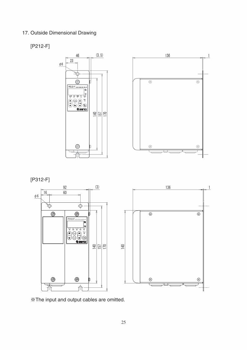
17. Outside Dimensional Drawing
[P212-F]
[P312-F]
※The input and output cables are omitted.
25

18. Warranty
The warranty shall continue in effect for one year from the date of shipping.
(However, the warranty period is calculated based on 8-hour operation a day.)
[Warranty conditions]
1. If failure or break is caused to the Controller by any defect in the design, material or
workmanship of the Controller in the normal usage in accordance with the precautions
described in the Instruction Manual, labels put on the Controller, and others during the
warranty period, we shall provide free repair or part replacement.
2. However, even if it is within the warranty period, following cases shall not be covered
under our warranty:
① Failure or break caused by a fire, an earthquake, a flood or the like, or unspecified
power source (voltage, frequency)
② Failure caused by improper handling or operation
③ Failure caused by handling against the usage, specifications or precautions described
in the Instruction Manual
④ Failure or break caused by remodeling, disassembly or the like conducted without our
consent
The contents of this Instruction Manual are subject to change for functional improvement
without notice.
Issued in February 2015
26

27

SANKI COMPANY LIMITED.
◇Sendai Office Tel: +81-22-263-8345 Fax: +81-22-263-8354
◇Tokyo Office Tel: +81-3-3493-6187 Fax: +81-3-3493-6195
◇Nagoya Office Tel: +81-52-691-1147 Fax: +81-52-692-1915
◇Osaka Office Tel: +81-6-6746-8222 Fax: +81-6-6746-8224
http://www.sanki-web.co.jp
28