instructions and comments screen shots, images, … design...instructions and comments screen shots,...
TRANSCRIPT

CELERE 2013 - Design Instructions and Tutorial 2013-JAN-09
1
Instructions and comments Screen shots, images, and diagrams Computer-Aided Design (CAD) image of a sample test cell showing the three layers separated in an “exploded” view. For CELERE, each team designs the (black) middle layer which will be sandwiched between the two standard plates with air vents at their top. VERY IMPORTANT! The channel(s) cut in the middle layer must extend from the base to the air vents to enable the capillary action. The liquid won’t rise if (1) the liquid can’t enter the channel(s) or (2) the air above the liquid can’t escape.
CAD image of the example test cell assembled, with the three layers together.
You will use the free CAD software package, DraftSight, and a provided template to design and draw the middle layer of the test cell. Your submitted drawing will be used to fabricate the middle layer. In this image, the black is the template for the middle layer, the green shows the air vents in the front and back layers, and the red shows the channels in which the liquid will rise.

CELERE 2013 - Design Instructions and Tutorial 2013-JAN-09
2
Portland State University (PSU) will cut your team’s middle layer, with its unique channel(s), out of black acrylic using a computer-controlled laser cuter and your CAD drawing.
PSU will assemble your test cell and mount it in a container so that its base is within a liquid reservoir.

CELERE 2013 - Design Instructions and Tutorial 2013-JAN-09
3
The test cell and the reservoir will be placed on an experiment rig between a video camera and a light source (so the test cell will be back lit).
The experiment rig will be placed inside a drag shield at the top of PSU’s Dryden Drop Tower. When everything is ready, the drag shield and the experiment rig will be dropped and fall for 2.1 seconds during which time it will experience apparent near weightlessness (i.e., microgravity). During the drop, the camera will image the capillary rise of the liquid inside the channel(s).
Sample images every 0.167 s.
One option for analyzing your results is through NASA’s Spotlight software, which can be freely downloaded at: http://microgravity.grc.nasa.gov/spotlight/ In this example, Spotlight is being used to track the location of the meniscu, i.e., liquid-air interface, from frame to frame as it rises within the channels. In this image, up is the left and down is to the right. Further-more, it is the lowest (farthest right) point on the meniscus surface that is being tracked.
Camera
Test cell in Reservoir
Light

CELERE 2013 - Design Instructions and Tutorial 2013-JAN-09
4
Spotlight can output a data file, which in this example includes the position of the meniscus for each sequential frame. In standard video, like that used for CELERE, there are 30 frames per second.
Spotlight data files can be imported into Microsoft Excel or similar software for data analysis and plotting.
In this example plot, the fluid rise within the channels can be seen. The blue and red reveal the rise in the narrow (left) and shrinking (right) channels, respectively (as seen in the images on the previous pages). The green shows the rise at the base of the test cell, before the channel splits. The results show that the fluid generally rose at constant rate, but where the rate was lower in the narrow (left) channel. Analysis such as this is not required, but each CELERE team is required to briefly report on their findings.
0
20
40
60
80
100
120
140
160
180
0 0.5 1 1.5 2
Posi
tion
(mm
)
Time (s)
Position vs. Time Square Channel
Tapered Channel
Rect. Channel

CELERE 2013 - Design Instructions and Tutorial 2013-JAN-09
5
Tutorial: Capillary Rise in a Bifurcating Channel Through this tutorial, you will use CAD to draw the split Y-shaped channel shown in the middle-layer figure below.
As a start:
1. Download DraftSight for free from: http://www.3ds.com/products/draftsight/free-cad-software/ 2. Get the CELERE drawing template, CELERE_TestCell_Template.dwg, from NASA or PSU.
While this tutorial uses many of the tools available in DraftSight, it is not an exhaustive instructional tool. For more guidance on DraftSight, download the user guide at: http://www.3ds.com/fileadmin/PRODUCTS/DRAFT_SIGHT/PDF/GETTING-STARTED-GUIDE.pdf. Another place for useful information on DraftSight is the program’s Help documentation. Launch DraftSight and press F1 or navigate to the Help menu from the main menu toolbar at the top of the screen.
It is strongly recommended that you go through all of this tutorial’s steps at least once, especially if you are not familiar with DraftSight! The CELERE tutorial and design instructions were developed by Andrew Wollman (Portland State University, Portland, Oregon) and edited by Dennis Stocker (NASA Glenn Research Center, Cleveland, Ohio).

CELERE 2013 - Design Instructions and Tutorial 2013-JAN-09
6
Instructions and comments Screen shots, images, and diagrams Launch DraftSight and open the drawing template, CELERE_TestCell_Template.dwg. A screen similar to that on the right will be visible, but the background will be black. The background in this tutorial has been changed to white to make it easier to read.
The template file, which provides the test cell outline including these main features:
• Border: The channel(s) that you design must fit within the border.
• File name: The file name appears at the top of the test channel so PSU can identify your middle layer and tell it apart from those of other teams.
• Green slot: The green slot is where the air will exit out the front and rear layers of the assembled test cell. The channel(s) you design must extend into the green slot.
DO NOT ALTER THE TEST CELL OUTLINE BLOCK IN ANY WAY!
The template file includes several unique layers, where the most important layer is the CUT layer. Lines drawn on this layer will tell the laser cutter to cut through the acrylic. Make sure your channel design is on the CUT layer. Items not on the cut layer will not be cut or printed at all. The other layers should not be used and are either DraftSight default layers or used by PSU. DO NOT MODIFY THE LAYERS IN ANY WAY! There are two tabs at the bottom of the template file. Make sure you are drawing in the Model tab. Sheet1 should not be used.

CELERE 2013 - Design Instructions and Tutorial 2013-JAN-09
7
Do not modify the provided CELERE template file. Instead re-save the file with a unique name and modify that copy. The file name of your submitted drawing will be used to identify your part and help PSU keep track of all the experiments. Especially for that final drawing, use the following steps to format and name your new file. In the menu toolbar, navigate to: File Save As… Save the template file as a new file using the following convention: CELERE_2013_<StateInitials>_<OrgAbbrev>_<AdvisorLastName>.dwg For example: CELERE_2013_OR_PSU_Wollman.dwg
Field Description
<StateInitials> Use the two-letter mailing abbreviation for your state or territory, where they are listed below for reference.
<OrgAbbrev>
An abbreviation for your team’s organization, e.g., school, Scout troop, etc. For example: Franklin Middle School = FMS Helen Keller School for the Blind = HKSB Girl Scout Troop 123 = GST123 In the case of schools, please use the school name for the abbreviation rather than the name of a school club.
<AdvisorLastName>
The end of the file name should be the last name of the team’s adult advisor, e.g., teacher, Scout leader, etc., who serves as the team’s principal contact with NASA.
US State Initial US State Initial US State Initial US Territory Initial Alabama AL Louisiana LA Ohio OH American Samoa AS Alaska AK Maine ME Oklahoma OK District of Columbia DC Arizona AZ Maryland MD Oregon OR Guam GU
Arkansas AR Massachusetts MA Pennsylvania PA Northern Mariana Islands MP
California CA Michigan MI Rhode Island RI Puerto Rico PR Colorado CO Minnesota MN South Carolina SC U.S. Virgin Islands VI
Connecticut CT Mississippi MS South Dakota SD Delaware DE Missouri MO Tennessee TN
Florida FL Montana MT Texas TX Georgia GA Nebraska NE Utah UT Hawaii HI Nevada NV Vermont VT Idaho ID New Hampshire NH Virginia VA Illinois IL New Jersey NJ Washington WA Indiana IN New Mexico NM West Virginia WV
Iowa IA New York NY Wisconsin WI Kansas KS North Carolina NC Wyoming WY
Kentucky KY North Dakota ND

CELERE 2013 - Design Instructions and Tutorial 2013-JAN-09
8
Begin drawing a “Y” shaped, split channel by selecting the POLYLINE command icon. A poly line is a group of connected straight and arced lines. For this example, we will use a poly line to outline the borders of the capillary channel of the test cell.
If you are going to free sketch the channel, do so within the borders of the test cell margins. Since this example problem uses predefined geometry we’ll work off to the right of the test cell. Note: The test channel in this tutorial is not the one pictured in the introductory overview. Off to the right of the Test Cell outline, select the first point of the POLYLINE.
To make a horizontal line 28 mm long, hold the cursor off to the right of the first selected point. Make sure the white horizontal guide line appears and holds your line horizontal. Type 28 <space>. You have told the program to draw a line 28 mm to the right of the original point. The space bar executes the command.

CELERE 2013 - Design Instructions and Tutorial 2013-JAN-09
9
To draw a vertical line 50 mm long, move the cursor vertically up from the second point. Make sure the white vertical guide line appears and holds your line vertical.
Type 50 <space>.
You can also identify the location of a line endpoint by typing in relative coordinates. To draw a line 100 mm long at a 100 degree angle off of horizontal, type @100<100 <space>.

CELERE 2013 - Design Instructions and Tutorial 2013-JAN-09
10
A polyline can also have arcs, so draw an arc at the end of the last line segment. To enter the arc mode, type A <space>.
You now need to define the size of the arc, which will be a 10 mm semi-circle tangent with a yet-to-be-drawn line parallel with the angled line. We therefore want the arc’s diameter to be perpendicular to the line we just drew. Geometry sets this point at 10 degrees off horizontal from our current location. Type @10<10 <space>.
You are still in arc mode. To get back into line mode type L <space>.

CELERE 2013 - Design Instructions and Tutorial 2013-JAN-09
11
To finish the first half of the channel, type @105<-80 <space>.
You are now done with POLYLINE command. Type <space> to exit POLYLINE command. You can also simply press the escape <Esc> key.
Save the drawing using Ctrl+S or the Save icon.
Entrance region effects act to slow and complicate the liquid flows in the test cell, so you should eliminate those effects as much as possible. To do this, you can round the corners at the bottom of the channel using the fillet command. Click on the FILLET command icon
CELERE 2013 - Design Instructions and Tutorial 2013-JAN-09
12
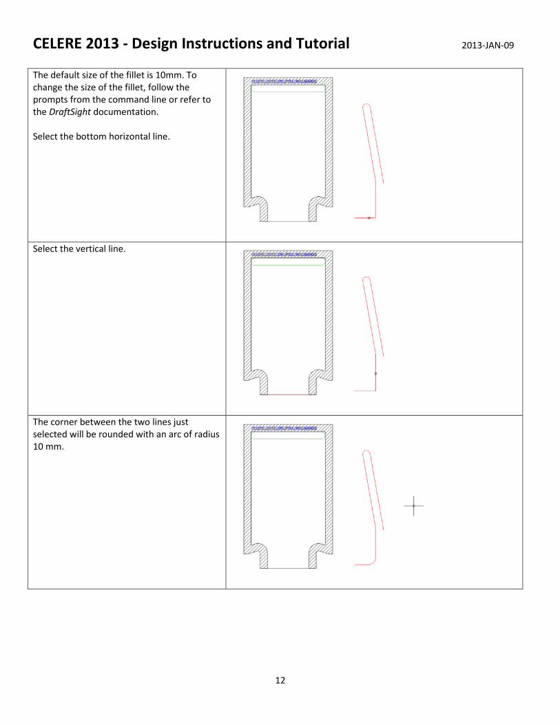
The default size of the fillet is 10mm. To change the size of the fillet, follow the prompts from the command line or refer to the DraftSight documentation. Select the bottom horizontal line.
Select the vertical line.
The corner between the two lines just selected will be rounded with an arc of radius 10 mm.

CELERE 2013 - Design Instructions and Tutorial 2013-JAN-09
13
Make one more fillet and round the corner between the vertical and diagonal line. Right click on the screen and select Repeat FILLET.
Again sticking with the default size of 10 mm, select the vertical line.
Select the diagonal line on the left, just above the vertical line.

CELERE 2013 - Design Instructions and Tutorial 2013-JAN-09
14
The corner where the two lines connect will round. You are done with FILLET tool.
Save the drawing using Ctrl+S or the Save icon.
We have only drawn one half of the channel. Let’s mirror the existing channel to make the “Y” shape we set out to make. Select the MIRROR command icon.
The command line prompts us to select the features we wish to mirror. Select the POLYLINE just drawn. Press <space>.

CELERE 2013 - Design Instructions and Tutorial 2013-JAN-09
15
Now you need to identify the line on which to mirror. Select the endpoint of the diagonal line of the POLYLINE.
Drag the mouse courser directly down and left click.
To avoid deleting the original poly line, type ‘n’ and press space bar. You are now done with MIRROR tool.
Save the drawing using Ctrl+S or the Save icon.

CELERE 2013 - Design Instructions and Tutorial 2013-JAN-09
16
The channel we have drawn is made up of two polylines, the one you drew, and the one you created using the mirror command. Join these two polylines together making the channel one poly line using the WELD command. Click on the WELD command icon.
Select both halves of the channel. Press <space> to execute the command. You are now done with WELD command.
If you hover the mouse cursor over the channel you will see that the whole channel is highlighted. This lets you know that the two poly lines have been connected into one polyline.
Save the drawing using Ctrl+S or the Save icon.
You need to identify the bottom center of the channel for later. For now, draw a simple line. Click on the LINE command icon.

CELERE 2013 - Design Instructions and Tutorial 2013-JAN-09
17
Select the end point of the line on the left of the channel.
Select the endpoint of the line on the right of the channel.
You will notice we are still in LINE command. To exit the LINE command, press escape <Esc>.

CELERE 2013 - Design Instructions and Tutorial 2013-JAN-09
18
You are done with LINE command.
Save the drawing using Ctrl+S or the Save icon.
Trim away the extra lines using the TRIM command to do this. Select the TRIM command icon
Select the bottom horizontal line of the polyline to the left of the line just drawn.

CELERE 2013 - Design Instructions and Tutorial 2013-JAN-09
19
Press <space> to select the entry.
Select the bottom horizontal lines at the bottom of the polyline.
Press <Esc> to exit the TRIM command. You are now done with the TRIM command.

CELERE 2013 - Design Instructions and Tutorial 2013-JAN-09
20
Now you need to move the polyline representing the channel into the test cell on the left. To do this, you will use the move command. Using the mouse courser, select the channel polyline (only).
Click the right mouse button and a pop up window will appear. Select Move from the menu, about midway down.
You need to select a base point from which to move the polyline into the center of the test cell. You have a midpoint of the line at the bottom of the channel polyline and at the bottom of the test cell. Therefore the center of the line at the bottom of the channel will be a good option for the base point. Select the midpoint of the line drawn at the bottom of the channel.

CELERE 2013 - Design Instructions and Tutorial 2013-JAN-09
21
Move courser over to the midpoint of the red line at the bottom of the test cell. Left click.
You are done with Move command.
You should now clean up the work space. Select the leftover line to the right of test cell and delete it. You can press the <Delete> key or right click and select Delete from the pop up window.

CELERE 2013 - Design Instructions and Tutorial 2013-JAN-09
22
You may notice that the channel does not rise all the way to the green slot. Therefore there is no way for the air to escape and the liquid will not rise along the channel. You must stretch the channel up to the green slot.
Save the drawing using Ctrl+S or the Save icon.
Select the STRETCH command icon.
You need to select the arcs and lines of the channel and the best way to do that is by the INTERSECTION SELECTION method. To do this you will want to move the mouse cursor to the left. Therefore start with the cursor to the right of the channel as seen in the figure, and then press the left mouse button.

CELERE 2013 - Design Instructions and Tutorial 2013-JAN-09
23
Now move the mouse cursor to the left and a green dashed box will appear. This is the INTERSECION SELECTION box. Any object that is intersected by the dashed line and any object within the box will be added to the selection. Left click.
Press <space> to complete selection process.
You are going to stretch the channel such that the tops of the two arcs reach the top of the green slot. Select the top of one of the arcs.
CELERE 2013 - Design Instructions and Tutorial 2013-JAN-09
24
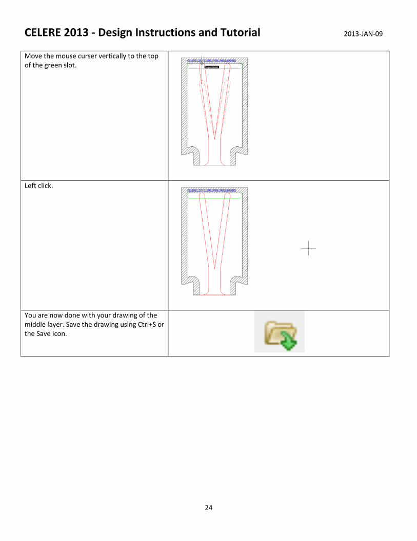
Move the mouse curser vertically to the top of the green slot.
Left click.
You are now done with your drawing of the middle layer. Save the drawing using Ctrl+S or the Save icon.