instructions for krm ho 001 - krmodels.com.au · instructions for krm ho 001 ngax/whx etched brass...
TRANSCRIPT

Instructions for KRM HO 001 NGAX/WHX Etched Brass Walkway & Ladder Kit
“Please take the time to read the instructions for this kit, as with any etched brass detail parts kit, the parts are small, fragile and can be easily lost or damaged. I don’t like reading instructions anymore than anyone else, but it will make a difference to the end result of this kit.”
Keiran Ryan
Introduction
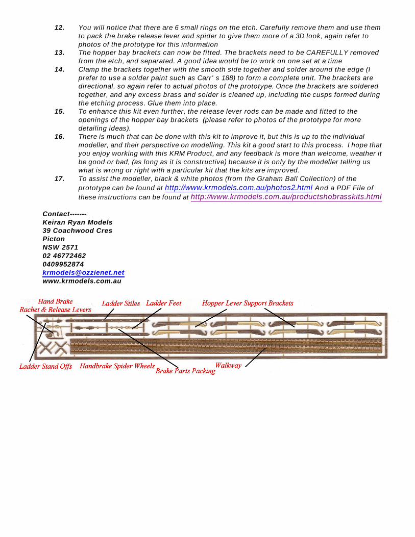
This kit was designed to detail and improve the look of the ARKits NGAX/WHX Wheat Hopper. The kit features, a 0.3mm etch fret with see thru walkway, ladder, ladder feet and stand off, as well as the hopper bay lever supports. The kit also includes as an optional extra, some brake gear components which may or may not be used at your discretion.
This kit has come about due to my need to have the NGAX Wheat Hopper super detailed. The kit aims to go in that direction. Other modellers have information on what components can be used to improve the wagon even further than this kit allows, but the kit is a great starting point for a much better looking wagon, I am sure you will agree. I won’t be going into numbers, changes, codes of wagons, and various other information, as this can be found else where.
Lets got ready tooooo modeeeeelllllllll !!!!!!!!!
1. Re-Read the instructions (Yeah I Know!!!!!!)2. Do not use the ladder provided with the original kit, but instead use the
superseded ladder supplied separately.3. Using a 0.3mm drill, clean out the holes in the ladder stiles, You will note that the superseded
ladder has the feet and stand-offs as a part of the ladder etch4. With a 0.4mm drill, clean out the holes in the brake spiders and brake release levers.5. Using a sharp pointed pair of stainless steel scissors cut the components out of the fret, with
the scissors at a 45-degree angle against the actual component. This allows most of the tab to be removed when cutting, minimising the need to clean up later. (Do be careful with the walkway and the ladder so as not to warp, bend or damage any of these components)
6. The ladder can be constructed using the fold and hold method or by locating the ladder stiles in the KRM Misc 004 Ladder Forming Support Jig (available separately on www.krmodels.com.au/products.html), and soldering 0.3mm brass wire through the rung holes. The ladder for this kit is 12” wide, so follow the instructions in the forming jig for a nice fine sharp ladder. The hold and fold method uses the ladder stile tabs to hold the ladder stiles together, whilst the ladder is formed with 0.3mm brass wire rungs. The best tool to help fold the ladder is the “Hold & Fold” available from Ian Millard at www.irmodels.com. This tool is an essential piece of equipment if you are intending to work with brass etchings as it provides the ability to obtain sharp crisp fold lines.
7. Solder the rungs in place and clean up the excess wire from the outside of the rungs, and clean up the remaining material with a fine file and wet & dry paper, clean up with warm soapy water when finished soldering and sanding clean.
8. Using the measurements supplied on the cardboard template (Supplied with superseded ladder), drill the holes in the bulkhead to locate the ladder stand-offs. Check the location of the standoffs before you drill the holes. The holes should be drilled using 0.4mm drill.
9. The completed ladder can be painted & fitted to the model at a later stage.10. Remove the walkway from the fret, and clean up the excess tab material with wet and dry
paper, being careful not to bend or damage the walkway etch. You will need to test fit the walkway to the risers on the top of the hopper. The simplest way to secure the walkway is to paint the walkway first, then glue the walkway on the risers of the original kit, using you glue of choice –SPARINGLY--. (Shelley’s Acrylic Kwikgrip is my preferred option) but make sure that you DON’T fill any of the holes with glue, as this will detract from the final finish of the kit.
11. The brake gear (an optional extra) can be fitted to the model in the appropriate locations (refer to photos of the model for information on location and position).
12. You will notice that there are 6 small rings on the etch. Carefully remove them and use them to pack the brake release lever and spider to give them more of a 3D look, again refer to photos of the prototype for this information
13. The hopper bay brackets can now be fitted. The brackets need to be CAREFULLY removed from the etch, and separated. A good idea would be to work on one set at a time
14. Clamp the brackets together with the smooth side together and solder around the edge (I prefer to use a solder paint such as Carr’s 188) to form a complete unit. The brackets are directional, so again refer to actual photos of the prototype. Once the brackets are soldered together, and any excess brass and solder is cleaned up, including the cusps formed during the etching process. Glue them into place.
15. To enhance this kit even further, the release lever rods can be made and fitted to the openings of the hopper bay brackets (please refer to photos of the prototype for more detailing ideas).
16. There is much that can be done with this kit to improve it, but this is up to the individual modeller, and their perspective on modelling. This kit a good start to this process. I hope that you enjoy working with this KRM Product, and any feedback is more than welcome, weather it be good or bad, (as long as it is constructive) because it is only by the modeller telling us what is wrong or right with a particular kit that the kits are improved.
17. To assist the modeller, black & white photos (from the Graham Ball Collection) of the prototype can be found at http://www.krmodels.com.au/photos2.html And a PDF File of these instructions can be found at http://www.krmodels.com.au/productshobrasskits.html
Contact-------Keiran Ryan Models39 Coachwood CresPicton NSW 257102 [email protected]