instructions to convert t130e1 track to … · tb 9-2350-369-20-1 technical bulletin instructions...
TRANSCRIPT

TB 9-2350-369-20-1
TECHNICAL BULLETIN
INSTRUCTIONS TO CONVERTT130E1 TRACK
TOT150F TRACK
USINGKIT 57K4269(2530-01-502-3401)
ONM113A3 FOV CARRIERS,M113A2 FOV CARRIERS,M548A1/A3 CARRIERS
ANDOSV/MBT VEHICLES
DISTRIBUTION STATEMENT A: Approved for public release; distribution is unlimited
HEADQUARTERS, DEPARTMENT OF THE ARMY 28 FEBRUARY 2007


TB 9-2350-369-20-1
WARNING SUMMARY
WARNING SUMMARY
This is a summary of critical WARNINGs in this bulletin. They are repeated here to let you know how importantthey are. Study these WARNINGs carefully; they can save your life and the lives of personnel you work with.
WARNING
Always wear eye protection when using a hammer. Eye injury may result ifmetal chips contact eyes.
WARNING
Improper number of track shoes may prevent track from being adjustedcorrectly, creating a safety hazard. Personnel may be killed and equipmentdamaged. For carriers with new track, ensure there are 63 track shoes onthe left side of carrier and 64 track shoes on the right side of carrier for theM113A2 FOV, M113A3 FOV and OSV. For the M548A1/A3, 66 track shoesare required for both sides.
WARNING
Do not use a crowbar on the track shoe pins to get leverage. Any scratchesmay cause the pin to break and cause the track assembly to fall off thevehicle while operating. This may kill soldiers and damage equipment. Usecrowbar as shown in the following steps to get leverage to install the endconnectors.
a

TB 9-2350-369-20-1
WARNING
Not getting the bolt tight enough may result in death to personnel anddamage to equipment if the end connectors fall off during movement of thevehicle.
For first aid information, see FM 4-25.11.
b

TB 9-2350-369-20-1
INSERT LATEST UPDATED PAGES/WORK PACKAGES. DESTROY SUPERSEDED DATA.
LIST OF EFFECTIVE PAGES/WORK PACKAGES
Dates of issue for original and updated pages/work packages are: Original 0 (28 February 2007)
TOTAL NUMBER OF PAGES FOR FRONT AND REAR MATTER IS 18 AND TOTAL NUMBER OF WORK PACKAGES IS 3 CONSISTING OF THE FOLLOWING:
Page/WP No.
*Change
No.
Page/WP No.
Change
No.
Page/WP No.
*Change
No. Cover 0 a/b 0
A/B blank 0
i-ii 0
WP 0001 00 0
WP 0002 00 0
WP 0003 00 0
Index-1/Index-2 blank 0
*Zero in this column indicates an original page
A/B blank

TB 9-2350-369-20-1
TECHNICAL BULLETIN HEADQUARTERSNo. 9-2350-369-20-1 DEPARTMENT OF THE ARMY
WASHINGTON, D.C., 28 February 2007
Technical Bulletin
MODIFICATION TO CONVERT M113A3 FOV CARRIERS, M113A2 FOV
CARRIERS,
M548A1/A3 CARRIERS AND OSV/MBT VEHICLES
T130E1 TRACK TO T150F TRACK
REPORTING ERRORS AND RECOMMENDING IMPROVEMENTSYou can help improve this publication. If you find any mistakes or if you know of a way to improve theprocedures, please let us know. Submit your DA Form 2028 (Recommended Changes to Publications andBlank Forms), through the Internet, on the Army Electronic Product Support (AEPS) website. The Internetaddress is http://aeps.ria.army.mil. If you need a password, scroll down and click on “ACCESS REQUESTFORM.” The DA 2028 is located in the ONLINE FORMS PROCESSING section of the AEPS. Fill out theform and click on SUBMIT. Using this form on the AEPS will enable us to respond quicker to your commentsand better manage the DA Form 2028 program. You may also mail, fax, or E-mail your letter or DA Form2028 direct to: AMSTA-LC-LPIT Tech Pubs, TACOM-RI, 1 Rock Island Arsenal, Rock Island, IL61299-7630. The e-mail address is [email protected]. The fax number is DSN 793-0726 or Commercial (309) 782-0726.
DISTRIBUTION STATEMENT A: Approved for public release; distribution is unlimited.
TABLE OF CONTENTS
Warning Summary
Safety Summary
WP Sequence No.
Introduction ........................................................................................................................................ 0001 00
Modification Procedures/Sequencing ................................................................................................ 0002 00
References ......................................................................................................................................... 0003 00
Index.................................................................................................................................................... Index-1
i
TB 9-2350-369-20-1
SAFETY SUMMARYGENERAL SAFETY INSTRUCTIONS.
This publication describes physical and chemical processes, which may cause injury or death to personnel ordamage to equipment if not properly followed. This safety summary includes general safety precautions andinstructions that must be understood and applied during operation and maintenance to ensure personnel safetyand protection of equipment. Prior to performing any task, the WARNINGs, CAUTIONs and NOTEs included inthat task shall be reviewed and understood.
WARNINGS, CAUTIONS, AND NOTES
WARNINGs and CAUTIONs are used in this publication to highlight operating or maintenance procedures,practices, conditions or statements, which are considered essential to protection of personnel (WARNING) orequipment (CAUTION). WARNINGs and CAUTIONs immediately precede the step or procedure to which theyapply. WARNINGs and CAUTIONs consist of four parts: heading (WARNING, CAUTION, and ICON), a statementof the hazard, minimum precautions, and possible result if disregarded. NOTEs are used in this publication tohighlight operating or maintenance procedures, practices, conditions or statements which are not essential toprotection of personnel or equipment. NOTEs may precede or follow the step or procedure, depending upon theinformation to be highlighted. The headings used and their definitions are as follows.
WARNING
Highlights an essential operating or maintenance procedure, practice,condition, statement, etc, which, if not strictly observed, could result ininjury to, long term health hazards for, or death of, personnel.
CAUTION
Highlights an essential operating or maintenance procedure, practice,condition, statement, etc, which, if not strictly observed, could result indamage to or destruction of equipment, or loss of mission effectiveness.
NOTE
Highlights an essential operating or maintenance procedure, condition, orstatement.
ii

TB 9-2350-369-20-1
INTRODUCTION 0001 00
0001 00-1
Purpose. The purpose of this technical bulletin (TB) is to replace the T130E1 track assembly and install the T150F track assembly. Kit 57K4269 provides all the parts to modify the sprocket carrier 10942567 and provides the crew tools for installing/removing T150 track. The T150 track assembly is procured separately through your unit funds. Thekit applies to the vehicles identified in Table 1. The kit is designed for either field or depot installation. General.
a. Priority. This bulletin is classified ROUTINE. b. End Item(s) or System(s) to be modified. Modification will be in accordance with Table 1.
Table 1. VEHICLES TO BE MODIFIED
NOMENCLATURE NSN PART NO. CAGEC
Carrier, Personnel, M113A3 2350-01-219-7577 8750170 19207
Carrier, 120mm Mortar, M1064A3 2350-01-369-6082 8750287 19207
Carrier, SICPS, M1068A3 2350-01-369-6086 8750288 19207
Carrier, Command Post, M577A3 2350-01-369-6085 8750286 19207
Carrier, Smoke Generator, M1059A3 2350-01-369-6083 8750290 19207
Carrier, Full Tracked, M58 2350-01-418-6654 12408400 19207
Carrier, Personnel, M113A2 2350-01-068-4077 8750024 19207
Carrier, Command Post, M577A2 2350-01-068-4089 8750025 19207
Carrier, Smoke Generator, M1059 2350-01-203-0188 8750136 19207
Carrier, SICPS, M1068 2350-01-354-5657 8750249 19207
Carrier, 120mm Mortar, M1064 2350-01-338-3116 8750248 19207
Carrier, Improved TOW, M901A1 2350-01-103-5641 8750063 19207
Carrier, FISTV, M981 2350-01-085-3792 8750031 19207
Carrier, Cargo, M548A1 2350-01-096-9356 8750029 19207
Carrier, Cargo, M548A3 2350-01-369-6081 8750289 19207
Opposing Forces Surrogate (OSV) M113A3/BMP-2 6920-01-420-4716 137490 57039
c. Module(s), (Components, Assemblies, Subassemblies, Boards and Cards) to be Modified. The following
items, whether installed in PLL/ASL or depot stock shall be modified. Not applicable.

TB 9-2350-369-20-1
INTRODUCTION (continued) 0001 00
d. Parts to be Modified. The following items, whether installed in PLL/ASL or depot stock shall be modified.Stocked parts shall be modified prior to issue and shall be marked so that it can be easily distributed thatmodification has been accomplished. Not applicable
e. Application.(1) Time Compliance Schedule: NA
(2) Level of Maintenance: The lowest level of maintenance authorized to perform modificationsdescribed by this TB is Unit Maintenance.
(3) Applied By: Unit/direct/general support/depot or contractor civilian personnel consisting of trackedvehicle mechanics (63Y-63T MOS) and/or heavy mobile equipment mechanics.
(4) Time Required: Time for TB application to one end item is estimated to be 4 man-hours.
(5) Modifications to be Applied to or Concurrently with the Application of this kit. None.
(6) Additional Information. Kit application will be concurrent with other depot overhaul/conversionprograms, as applicable. Mechanic and two helpers are required to apply this kit.
f. Technical Publications Affected/Changed:DMWR 9-2350-277 DMWR 9-2350-261 DMWR 9-2350-247 DMWR 9-2530-200/2TM 9-2350-277-10 TM 9-2350-261-10 TM 9-2350-247-10 TM 9-2350-366-10-1TM 9-2350-277-20 TM 9-2350-261-20 TM 9-2350-247-20 TM 9-2350-366-20-1TM 9-2350-277-24P TM 9-2350-261-24P TM 9-2350-247-24P TM 9-2350-366-24P-1
TM 9-2530-200-24g. Modification Kits/Parts, and Their Disposition.
(1) Kit(s)/Part(s) needed to apply this modification.
NOMENCLATURE CAGECPART NO.
NSNModification Kit, T150F Suspension Less Track(Does not include T150F Track Shoes, need to be ordered separately) 19207 57K4269
2530-01-502-3401
0001 00-2
(2) Contents of TB Kit. See Table 2.

TB 9-2350-369-20-1
INTRODUCTION (continued) 0001 00
Table 2. MODIFICATION KIT 57K4269
NSN NOMENCLATURE CAGEC PART NO. QUANTITY
3020-01-496-4445 Sprocket 19207 12474840 4 5340-01-496-7433 Adapter Ring 19207 12474843 4 2520-00-679-9657 Cushion 19207 8763180 4 5340-01-496-5173 Bracket 19207 12474841 2 5310-01-497-2285 Washer 19207 12474863 4 5310-00-809-5998 Washer 96906 MS27183-18 8 5305-00-071-2067 Screw 80204 B1821BH050C125N 4 5305-00-071-2069 Screw 80204 B1821BH050C150N 4 5306-01-132-3363 Bolt 96906 MS35764-1545 20 5305-01-496-6745 Bolt 96906 MS35764-1445 40 5220-01-504-2610 Tool, Alignment Trk Pin 19207 12474881 2 5220-01-496-3692 Track Gauge 19207 12474849 1 5120-01-496-3689 Remover 19207 12474798 1 5130-00-227-6681 Wrench Socket 55719 IM-362 1 5120-00-221-7959 Wrench Handle 19207 12474720 1 5120-00-473-6320 Handle Extension 55719 36A 1
0001 00-3

TB 9-2350-369-20-1
INTRODUCTION (continued) 0001 00
Not included in kit or 57K4269 but will be needed if being applied to a M981 or M901A1 formounting the track stowage brackets.
NSN NOMENCLATURE CAGEC PART NO. QUANTITY5305-00-071-2077 Screw 80204 B1821BH050C350N 4
(3) Bulk and Expendable Material. Not Applicable.
(4) Parts Disposition. Parts removed and not reinstalled are considered excess for kit application.Excess parts may be reused on another depot overhaul program or otherwise disposed of inaccordance with AR 725-50 or local salvage regulations. T130 E1 track removed from vehicle
will be inspected and classified IAW TM 9-2530-200-24 dated, March 2006. Refer to Table 1, listed in WP 0002 00.
00.h. Special Tools; Tool Kits; Jigs; Test, Measurement and Diagnostic Equipment (TMDE), and FixturesRequired. Common hand tools (wrenches, sockets, screwdrivers); metal cutting tools (drill bits, taps,saws); and other tools (drills, grinders, shop equipment) are furnished by the maintenanceshop/contractor.
REQUIRED COMMON TOOLS FOR INSTALLATION
NSN NOMENCLATURE CAGEC PART NO. QUANITY5120-01-240-6040 Crowbar 19207 11655778-5 1
4910-00-253-2478 Grease Gun 19207 10915142 15120-00-061-8546 Hammer 2 lb 19207 11677028-3 1
OR5120-01-399-9254 Hammer 4 lb 1CV05 1435G 15120-00-264-3796 Adjustable Wrench 19207 11655778-5 15120-00-041-4624 Track Fixture 19207 12253183 24240-00-052-3776 Industrial Goggles 19207 - 1
5180-00-177-7033 Gen. Mechanics ToolKit 19207 - 1
i. Modification Procedures. Refer to Modifications Procedures/Sequencing Work package for compliance.j. Calibration Requirements. No calibration is required of the modified vehicle.k. Weight and Balance Data. Weight and balance are not significantly affected. l. Quality Assurance Requirements.
(1) Perform Quality Assurance inspections to verify requirements of paragraph i, which define theminimum inspections to be performed. Documented Quality evidence of inspections performed andcompliance with requirements will be accomplished as specified by the maintenance Quality activity.
(2) Inspection.
(a) In-process Inspection. Perform monitoring-type inspection of processes to assure compliancewith requirements. The following items can only be monitored prior to completion of othersteps.1 Ensure track assemblies for T150F track have correct number of track shoes (63 left side,
64 right side M113A2 FOV, M113A3 FOV and OSV; 66 left and right side M548A1/A3).2 Ensure rework of components is accomplished in their workstations IAW requirements of
TB.m. Recording and Reporting of the Modification. Refer to DA Pamphlet 738-750.
(1) Marking Equipment. Not applicable.n. Material Change (MC) Number. Not applicable.o. Modification Identification. Not applicable.
END OF WORK PACKAGE
0001 00-4
TB 9-2350-369-20-1
MODIFICATION PROCEDURES/SEQUENCING 0002 00
THIS WORK PACKAGE COVERS:
General (page 0002 00-1), Disassembly (page 0002 00-2), Assembly (page 0002 00-5), Final Inspection(page 0002 00-12).
INITIAL SETUP:Maintenance LevelUnit
Tools and Special ToolsModification Kit 57K4269 (WP 0001 00)
Materials/PartsModification Kit 57K4269 (WP 0001 00)
ReferencesTM 9-2350-277-10TM 9-2350-277-20TM 9-2350-261-10TM 9-2350-261-20
References (continued)TM 9-2350-247-10TM 9-2350-247-20TM 9-2350-366-10-1TM 9-2350-366-20-1
Personnel RequiredTracked Vehicle mechanic (63Y-63T MOS) or heavymobile equipment mechanic and two helpers
Estimated Time To Complete the Task4 man-hours
Equipment ConditionsVehicle on level surface
Engine stopped (see your -10)Vehicle blocked (see your -10)
GENERAL
Scope.
This work package provides shop instructions for the installation of T150F Track Assembly for carriers listed inTable 1 (WP 0001 00). If working on a M981 or M901A1 you will need to add four screws - B1821BH050C350Nper vehicle to mount the track stowage brackets. The OSV does not have a stowage bracket for the spare trackshoes at this time.
Facilities.
No special facilities are required other than that required for Unit/Direct/General Support maintenance. (SeeTM 9-2350-277-10 and -20 for M113A3 FOV; TM 9-2350-261-10 and -20 for M113A2 FOV; TM 9-2350-247-10 and -20 for M548A1/A3; or TM 9-2350-366-10-1 and -20-1 for OSV/MBT).
Tools and Equipment.
a. Commonly used tools and equipment having application to unit maintenance, in general, will be furnished bythe maintenance activity/contractor.
b. Special tools and equipment having application to maintain M113A3 FOV carriers are listed in TM 9-2350-277-20 and TM 9-2350-277-24P, M113A2 FOV carriers are listed in TM 9-2350-261-20 and TM 9-2350-261-24P, M548A1/A3 carriers are listed in TM 9-2350-247-20 and TM 9-2350-247-24P, or OSV/MBT vehicles arelisted in TM 9-2350-366-20-1 and TM 9-2350-366-24P-1 will be furnished by the unit/direct/general supportactivity/contractor.
0002 00-1

TB 9-2350-369-20-1
MODIFICATION PROCEDURES/SEQUENCING (continued) 0002 00CAUTION
If vehicle has older Sprocket Wheel PN 8763352 it is necessary to replace itwith the current Sprocket Wheel PN 10942567 to convert to T150F track.
DISASSEMBLY
1. Removal of Components.
a. The following paragraphs provide disassembly procedures to the extent necessary for installing T150F TrackAssembly. Detailed procedures not contained herein may be found in applicable technical manuals(TM 9-2350-277-10 or -20 for the M113A3 FOV; TM 9-2350-261-10 or -20 for the M113A2 FOV; TM 9-2350-247-10 or -20 for the M548A1/A3; or TM 9-2350-366-10-1 or -20-1 for the OSV).
b. Parts to be retained for rework or reuse during assembly, and parts considered excess duringdisassembly of the M113A3 FOV carriers, are identified by name and part number in the disassemblyprocedures. Dispose of excess parts IAW instructions from AR 725-50.
c. Table 1 indicates parts that will be removed and reused, discarded, or considered excess, duringdisassembly/removal of T130E1 Track Assembly. The information to remove these items will beimmediately following the table. The parts listed for reuse will be installed during assembly.
d. Perform all disassembly and re-assembly steps for one track assembly. Then repeat all steps for theopposite side track assembly.
e. The following reference tasks are equipment conditions required for disassembly (any unique tasks willbe stated in the specific procedure):
(1) Vehicle on level surface.
(2) Engine stopped (see your -10).
(3) Vehicle blocked (see your -10)
Table 1. PARTS REMOVED AND REUSED, DISCARDED, OR EXCESS(QUANTITIES LISTED ARE FOR THE LEFT AND RIGHT SIDES)
SPARE TRACK SHOES FOR MODIFICATION OF T130E1 TRACK ASSEMBLY TO T150F TRACKASSEMBLY
** Parts to be removed and reused*** Parts to be removed and discarded
0002 00-2
NSN NOMENCLATURE CAGEC PART NO. QUANTITY** 2520-00-678-8382 Wheel, Sprocket 19207 10942567 2*** 2350-00-078-2908 Track Assembly
T130E119207 11677988 127or 166
*** 3020-00-141-1154 Sprocket, Wheel 19207 11678255 4*** 2520-00-679-9657 Cushion, Rubber 19207 8763180 4*** 5306-01-131-9825 Bolt, Self-locking 19207 MS35764-1435 40*** 5306-01-132-3363 Bolt, Self-locking 19207 MS35764-1545 20
*** 2530-00-078-2908 Track Shoe Assembly 19207 11677988-6 2*** 5310-00-682-5992 Track Shoe Assembly 19207 8763458 4*** 5305-00-071-2069 Screw, Cap, Hexagon 19207 B1821BH050C150N 4

TB 9-2350-369-20-1
MODIFICATION PROCEDURES/SEQUENCING (continued) 0002 00
DISASSEMBLY - Continued
2. Stowage Items.
These items are to be removed and disposition of parts is as indicated on Table 1.
a. Remove Stowed Track Shoe Assemblies.
(1) Remove four screws (B1821BH050C150N), flat washers (8763458), and two track shoeassemblies (11677988-6) stowed on the front of the vehicle.
Figure 1. Remove Stowed Track Shoe Assemblies
0002 00-3
TB 9-2350-369-20-1
MODIFICATION PROCEDURES/SEQUENCING (continued) 0002 00
DISASSEMBLY - Continued
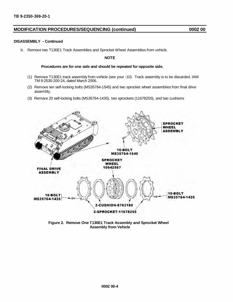
b. Remove two T130E1 Track Assemblies and Sprocket Wheel Assemblies from vehicle.
NOTE
Procedures are for one side and should be repeated for opposite side.
(1) Remove T130E1 track assembly from vehicle (see your -10). Track assembly is to be discarded. IAW TM 9-2530-200-24, dated March 2006.(2) Remove ten self-locking bolts (MS35764-1545) and two sprocket wheel assemblies from final drive
assembly.
(3) Remove 20 self-locking bolts (MS35764-1435), two sprockets (11678255), and two cushions(8763180) from sprocket wheel (10942567).
Figure 2. Remove One T130E1 Track Assembly and Sprocket WheelAssembly from Vehicle
0002 00-4

TB 9-2350-369-20-1
MODIFICATION PROCEDURES/SEQUENCING (continued) 0002 00
ASSEMBLY
1. Installation of Components.
a. General. Order of assembly of the vehicle will take place in the sequence shown in this TB. This willcover the components for installation of T150F Track Assembly.
b. Procedures. The following pages will cover the procedures for describing the installation of componentsfor installation of T150F Track Assembly.
c. Follow-through steps to complete the TB maintenance will be described in Follow - Through Steps.
0002 00-5
NSN NOMENCLATURE CAGEC PART NO. QUANITY2520-00-678-8382 Wheel, Sprocket 19207 10942567 23020-01-496-4445 Sprocket, Wheel 19207 12474840 45340-01-496-7433 Ring, Sprocket 19207 12474843 42520-00-679-9657 Cushion, Rubber 19207 8763180 45305-01-496-6745 Bolt, Self-locking 19207 MS35764-1445 405306-01-132-3363 Bolt, Self-locking 19207 MS35764-1545 20
2530-01-496-4444 Track Assembly 19207 12474844 127or166
Table 2. TRACK ASSEMBLY INSTALLATION COMPONENTS
TB 9-2350-369-20-1
MODIFICATION PROCEDURES/SEQUENCING (continued) 0002 00ASSEMBLY - Continued
NOTE
Procedures are for one side. Repeat these steps for the opposite side.
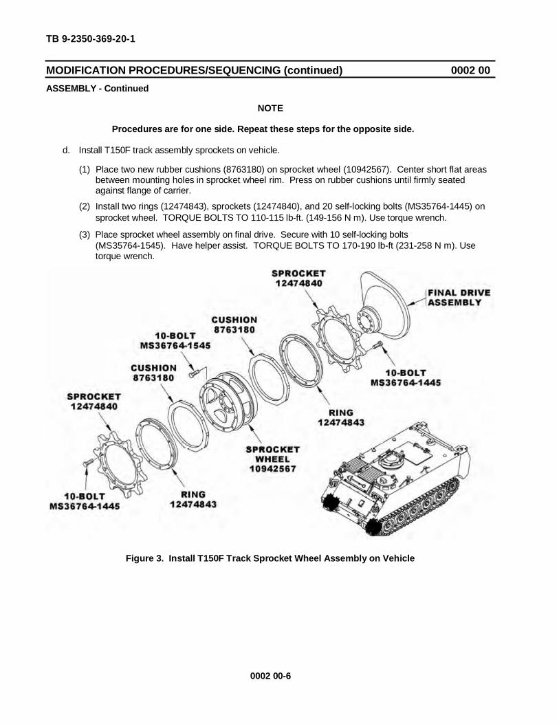
d. Install T150F track assembly sprockets on vehicle.
(1) Place two new rubber cushions (8763180) on sprocket wheel (10942567). Center short flat areasbetween mounting holes in sprocket wheel rim. Press on rubber cushions until firmly seatedagainst flange of carrier.
(2) Install two rings (12474843), sprockets (12474840), and 20 self-locking bolts (MS35764-1445) onsprocket wheel. TORQUE BOLTS TO 110-115 lb-ft. (149-156 N m). Use torque wrench.
(3) Place sprocket wheel assembly on final drive. Secure with 10 self-locking bolts(MS35764-1545). Have helper assist. TORQUE BOLTS TO 170-190 lb-ft (231-258 N m). Usetorque wrench.
Figure 3. Install T150F Track Sprocket Wheel Assembly on Vehicle
0002 00-6
TB 9-2350-369-20-1
MODIFICATION PROCEDURES/SEQUENCING (continued) 0002 00 ASSEMBLY - Continued e. Install T150F Track Assembly on vehicle (Figure 4 through Figure 8).
WARNING
Improper number of track shoes may prevent track from being adjusted correctly, creating a safety hazard. Personnel may be killed and equipment damaged. For carriers with new track, ensure there are 63 track shoes on the left side of carrier and 64 track shoes on the right side of carrier for the M113A2 FOV, M113A3 FOV and OSV. For the M548A1/A3, 66 track shoes are required for both sides.
CAUTION Be sure track shoe orientation matches that of the adjacent shoe. Center
guides can not be next to each other. NOTE
Track assembly can be installed from front to back or back to front. Going from the back to front can be easier with the sprocket wheel assembly to help push the track assembly over the top of the road wheels. Joining the track together will be between the sprocket wheel assembly and first road wheel or idler wheels and last road wheel.
If connecting the track at rear of vehicle (M113A2 FOV and M113A3 FOV only), have ramp closed and secured (see your -10) to allow access under the vehicle.
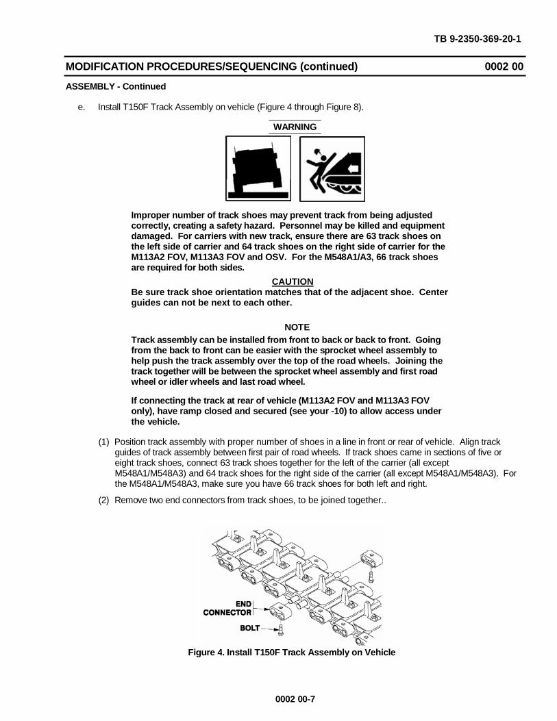
(1) Position track assembly with proper number of shoes in a line in front or rear of vehicle. Align track guides of track assembly between first pair of road wheels. If track shoes came in sections of five or eight track shoes, connect 63 track shoes together for the left of the carrier (all except M548A1/M548A3) and 64 track shoes for the right side of the carrier (all except M548A1/M548A3). For the M548A1/M548A3, make sure you have 66 track shoes for both left and right.
(2) Remove two end connectors from track shoes, to be joined together..
Figure 4. Install T150F Track Assembly on Vehicle
0002 00-7
TB 9-2350-369-20-1
MODIFICATION PROCEDURES/SEQUENCING (continued) 0002 00
ASSEMBLY – Continued
(3) Unblock vehicle (see your -10).
(4) Have helper drive vehicle forward or reverse until track assembly positions on sprockets.
(5) Have helper drive vehicle forward or reverse until track assembly is over idler wheels.
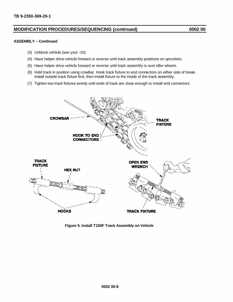
(6) Hold track in position using crowbar. Hook track fixture to end connectors on either side of break.Install outside track fixture first, then install fixture to the inside of the track assembly.
(7) Tighten two track fixtures evenly until ends of track are close enough to install end connectors.
Figure 5. Install T150F Track Assembly on Vehicle
0002 00-8

TB 9-2350-369-20-1
MODIFICATION PROCEDURES/SEQUENCING (continued) 0002 00
ASSEMBLY - Continued
(8) Place alignment track pin tool (12474881) over one pin on the outside track shoe and rest it on theother pin. Tighten both track fixtures evenly to pull the track assembly together until the alignment trackpin tool fits over and seats fully on both track shoe’s pins. Install the second alignment track pin toolon the inside track shoe pins.
(9) Remove the outside track fixture. Both alignment track pin tools will hold the track together. Leavethe other track fixture on the inside of the track shoe.
Figure 6. Install T150F Track Assembly on Vehicle
WARNING
Do not use a crowbar on the track shoe pins to get leverage. Anyscratches may cause the pin to break and cause the track assembly tofall off the vehicle while operating. This may kill soldiers and damageequipment. Use crowbar as shown in the following steps to get leverageto install the end connectors.
NOTE
Place end connector or similar size block on top of the two track shoesbeing joined. Use the crowbar under the track fixture connected to theinside track shoes end connectors and press down on the block/endconnector to get the right angle to install the end connector.
(10) Make sure the inside track fixture is tight enough to allow the helper to use the crowbar under it withenough pressure to get the slight degree of angle between the two track shoes to allow installingthe outside end connector. Use end connector or block to get the angle needed to install the endconnector. Use end connector or block as leverage to get angle needed to install end connector.
0002 00-9
TB 9-2350-369-20-1
MODIFICATION PROCEDURES/SEQUENCING (continued) 0002 00
ASSEMBLY - Continued
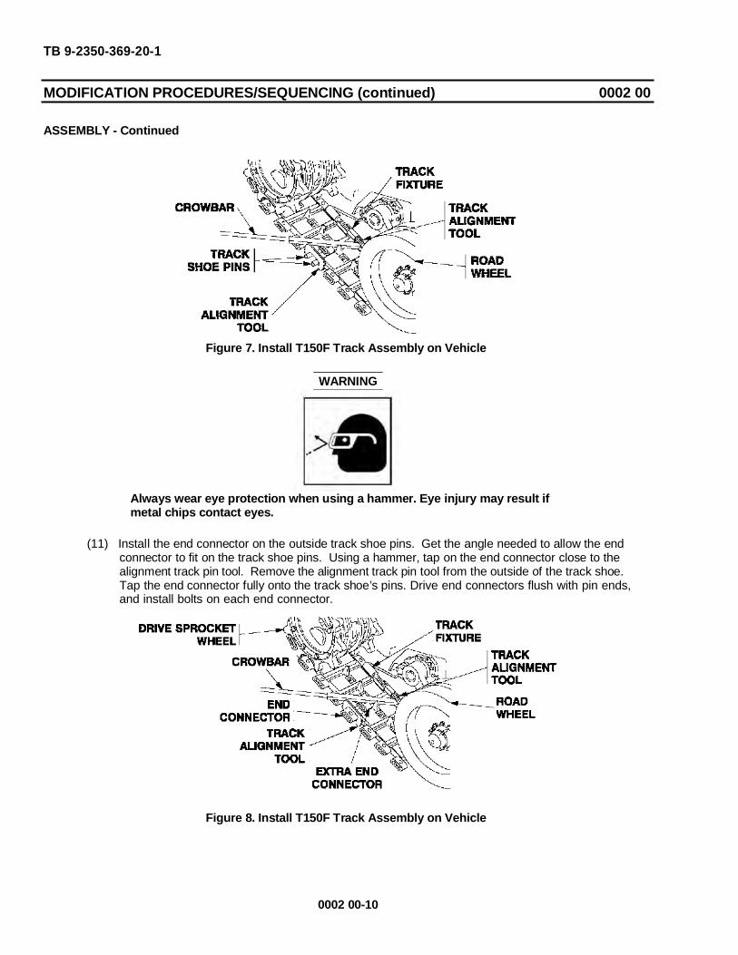
Figure 7. Install T150F Track Assembly on Vehicle
WARNING
Always wear eye protection when using a hammer. Eye injury may result ifmetal chips contact eyes.
(11) Install the end connector on the outside track shoe pins. Get the angle needed to allow the endconnector to fit on the track shoe pins. Using a hammer, tap on the end connector close to thealignment track pin tool. Remove the alignment track pin tool from the outside of the track shoe.Tap the end connector fully onto the track shoe’s pins. Drive end connectors flush with pin ends, and install bolts on each end connector.
Figure 8. Install T150F Track Assembly on Vehicle
0002 00-10

TB 9-2350-369-20-1
MODIFICATION PROCEDURES/SEQUENCING (continued) 0002 00
ASSEMBLY - Continued
(12) Install inside end connector. Only a slight amount or no leverage is needed to install the secondend connector if the outside end connector is already installed.
(13) With the end connector installed half way on the inside of the track shoe, remove the track fixtureand alignment track pin tool. Finish installing the end connector flush with the pin ends.
WARNING
Not getting the bolt tight enough may result in death to personnel anddamage to equipment if the end connectors fall off during movement of thevehicle. Torque each end connector bolt to the proper torque of 400-430 lb-ft(543-583 Nm).
NOTE
Mark the location of the end connectors so they can be torqued properly.
(14) TORQUE END CONNECTORS’ BOLTS TO 400-430 lb-ft (543-583 N m). Make sure to checkevery end connector bolt on the complete track assembly, even if it came in as a completeassembly.
(15) Repeat installation procedures to the opposite side of the vehicle.
(16) Adjust track tension (see your -10).
f. Install T150F Spare Track Shoes and Brackets on vehicle (Figure 9).
Table 3. SPARE TRACK SHOE INSTALLATION COMPONENTS(OSV DOES NOT HAVE A STOWAGE LOCATION FOR THE SPARE TRACK SHOES)
NSN NOMENCLATURE CAGEC PART NO. QUANITY
5340-01-496-5173 Bracket, Track,Stowage 19207 12474841 2
2530-01-496-4444 Track ShoeAssembly 19207 12474844 127or166
5310-01-497-2285 Washer, Flat, Square 19207 12474863 45305-00-071-2067 Screw, Cap, Hex 80204 B1821BH050C125N 45305-00-071-2069 Screw, Cap, Hex 80204 B1821BH050C150N 45310-00-809-5998 Washer, Flat 96906 MS27183-18 8
Not included in the kit (replaces B1821BH050C150N). For M981/M901A1 5305-00-071-2077 Screw, Cap, Hex 80204 B1821BH050C350N 4
0002 00-11
TB 9-2350-369-20-1
MODIFICATION PROCEDURES/SEQUENCING (continued) 0002 00
ASSEMBLY - Continued
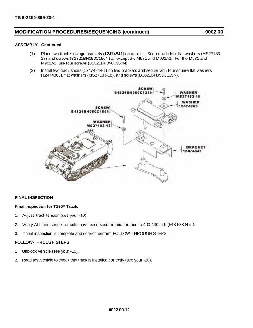
(1) Place two track stowage brackets (12474841) on vehicle. Secure with four flat washers (MS27183-18) and screws (B1821BH050C150N) all except the M981 and M901A1. For the M981 andM901A1, use four screws (B1821BH050C350N).
(2) Install two track shoes (12474844-1) on two brackets and secure with four square flat washers(12474863), flat washers (MS27183-18), and screws (B1821BH050C125N).
FINAL INSPECTION
Final Inspection for T150F Track.
1. Adjust track tension (see your -10).
2. Verify ALL end connector bolts have been secured and torqued to 400-430 lb-ft (543-583 N m).
3. If final inspection is complete and correct, perform FOLLOW-THROUGH STEPS.
FOLLOW-THROUGH STEPS
1 Unblock vehicle (see your -10).
2. Road test vehicle to check that track is installed correctly (see your -20).
0002 00-12

3. CRITICAL SAFETY ITEM CHECK: After 30 to 60 miles of operation with new track, check torque on all end connector bolts. TORQUE TO 400-430 lb-ft (543-583 N m).
4. CRITICAL SAFETY ITEM CHECK: After 1500 miles of operation with new track reverse track (see your - 20). This extends the life of the track. Keep a record of when track is installed/reversed.
END OF WORK PACKAGE
TB 9-2350-369-20-1
MODIFICATION PROCEDURES/SEQUENCING (continued) 0002 00
ASSEMBLY - Continued
WARNING
Not getting the bolt tight enough may result in death to personnel anddamage to equipment if the end connectors fall off during movement of thevehicle. Torque each end connector bolt to the proper torque of 400-430 lb-ft(543-583 Nm).
0002 00-13/-14 Blank


TB 9-2350-369-20-1
REFERENCES 0003 00
SCOPEThis work package lists technical manual and miscellaneous publications referenced in this bulletin.
TECHNICAL MANUALS
Operator’s Manual for Carrier, Personnel, Full Tracked, ArmoredM113A3 2350-01-219-7577 (EIC AEY), Carrier, Command Post, LightTracked M577A3 2350-01-369-6085 (EIC AE7), Carrier, SmokeGenerator, Full Tracked M1059A3 2350-01-369-6083 (EIC AFA),Carrier, Mortar, 120-Mm M121, Self-Propelled M1064A3 2350-01-369-6082 (EIC AE8), Carrier, Standardized Integrated Command PostSystem (SICPS) M1068A3 2350-01-369-6086 (EIC AFC), Carrier,Mechanized Smoke Obscurant M58 2350-01-418-6654 (EIC5CG)
Unit Maintenance Manual for Carrier, Personnel, Full Tracked,Armored M113A3 2350-01-219-7577 (EIC AEY), Carrier, CommandPost, Light Tracked M577A3 2350-01-369-6085 (EIC AE7), Carrier,Smoke Generator, Full Tracked M1059A3 2350-01-369-6083 (EICAFA), Carrier, Mortar, 120-Mm M121, Self-Propelled M1064A3 2350-01-369-6082 (EIC AE8), Carrier, Standardized Integrated CommandPost System (SICPS) M1068A3 2350-01-369-6086 (EIC AFC), Carrier,Mechanized Smoke Obscurant M58 2350-01-418-6654 (EIC5CG)
Operators Manual For Carrier, Personnel, Full-Tracked, Armored2350-01-068-4077, Carrier, Command Post, Light, Tracked, 2350-01-068-4089, Carrier, Mortar, 107-MM, M30, Self-Propelled M106A22350-01-069-693 Carrier, Mortar, 81-Mm, M29A1, Self PropelledM125A2 2350-01-068-4087 Carrier, Smoke Generator, Full Tracked2350-01-203-0188 Carrier, Mortar, 120-Mm Self-Propelled, M1062350-01-338-3116 Carrier, Standardized Integrated Command PostM1068 2351-01-354-5657
Unit Maintenance Manual For Carrier, Personnel, Full Tracked:Armored, M113A2 2350-01-068-4077, Carrier, Command Post, LightTracked, M577A2 2350-01-068-4089, Carrier, Mortar, 107-MM, M30;Self-Propelled, M106A2 2350-01-069-6931 Carrier, Mortar, 81-MM,M29A1; Self-Propelled, M125A2 2350-01-068-4087 Carrier, Mortar,120-MM, M121, Self-Propelled, M1064 2350-01-338-3116 Chassis,Gun, Anti-Aircraft Artillery, 2350-01-099-8929, Carrier, SmokeGenerator, Full Tracked, M105 2350-01-203-0188 Combat Vehicle,Anti-Tank, Improved Tow Vehicle, M901A1, 2350-01-103-5641
Operators Manual For Carrier, Cargo, Tracked, 6-Ton, M548A1 2350-01-096-9356, M548A3 2350-01-369-6081, Carrier, Electronic WarfareSystems, Tracked, 6-Ton, M1015A1 2350-01-136-8745
Unit Maintenance For Carrier, Cargo, Tracked, 6-Ton M548A1 2350-00-096-9356, M548A3 2350-01-369-6081, Carrier, Electronic WarfareSystems, Tracked, 6-Ton M1015A1 2350-01-136-8745
Operator’s Manual for Opposing Forces Surrogate Training Systems,Opposing Forces, Surrogate Vehicle (OSV) M113A3/BMP-2 (2350-01-420-4716); Main Battle Tank (MBT), M113A3/MBT (2350-01-513-4793) Hull
TM 9-2350-277-10
TM 9-2350-277-20
TM 9-2350-261-10
TM 9-2350-261-20
TM 9-2350-247-10
TM 9-2350-247-20
TM 9-2350-366-10-1
0003 00-1
TB 9-2350-369-20-1
REFERENCES 0003 00
Unit Maintenance Manual for Opposing Forces Surrogate TrainingSystems, Opposing Forces, Surrogate Vehicle (OSV) M113A3/BMP-2(2350-01-420-4716); Main Battle Tank (MBT), M113A3/MBT (2350-01-513-4793) Hull
TM 9-2350-366-20-1
Other Publications.
First Aid FM 4-25.11Requisition, Receipt and Issue System AR 725-50The Army Maintenance Management Systems (TAMMS) DA Pam 738-750
FORMS
Recommended Changes to Publications and Blank Forms DA 2028
END OF WORK PACKAGE
0003 00-2

TB 9-2350-369-20-1
INDEX
A - H
IIntroduction
General .....................................................................................................................................0001 00-1Purpose.....................................................................................................................................0001 00-1
J - L
M
Modification Procedures/SequencingAssembly ..................................................................................................................................0002 00-5Disassembly..............................................................................................................................0002 00-2Final Inspection .........................................................................................................................0002 00-12General .....................................................................................................................................0002 00-1
N - Q
R
References................................................................................................................................0003 00-1
S - Z
Index-1/Index-2 blank


Distribution: To be distributed in accordance with the initial distribution number (IDN) 344871, requirements for TB 9-2350-369-20-1
By Order of the Secretary of the Army:
PETER J. SCHOOMAKER General, United States Army
Chief of Staff Official:
JOYCE E. MORROW Administrative Assistant to the
Secretary of the Army0703002


RECOMMENDED CHANGES TO PUBLICATIONSAND BLANK FORMS
For use of this form, see AR 25-30; the proponent agency isODISC4.
Use Part II (reverse) for RepairParts and Special Tools Lists(RPSTL) and SupplyCatalogs/Supply ManualsSC/SM).
Date
TO: (Forward to proponent of publication or form) (Include ZIP Code) FROM: (Activity and location) (include ZIP code)
PART I - ALL PUBLICATIONS (EXCEPT RPSTL AND SC/SM) AND BLANK FORMSPUBLICATION/FORM NUMBER
TB 9-2350-369-20-1
DATE
28 February 2007
TITLEModification to Convert M113A3 FOVCarriers, M113A2 FOV Carriers, M548A1/A3Carriers And OSV/MBT Vehicles, T130E1Track to T150F Track
ITEM PAGE PARA LINE FIGURENO.
TABLE RECOMMENDED CHANGES AND REASON
0052 00-4 Inspection Step 1 WP reference should be (WP 0003 00)
*Reference to line numbers within the paragraph or subparagraph.TYPED, GRADE OR TITLE TELEPHONE EXCHANGE/AUTOVON, PLUS
EXTENSIONSIGNATURE
DA FORM 2028, FEB 74 REPLACES DA FORM 2028, 1 DEC 68, WHICH WILL BE USED.
SAMPLE

TO: (Forward direct to addresseelisted in publication)
FROM: (Activity and location) (IncludeZip Code)
Date
PART II - REPAIR PARTS AND SPECIAL TOOL LISTS AND SUPPLY CATALOGS/SUPPLY MANUALS
PUBLICATION/FORM NUMBER
TB 9-2350-369-20-1
DATE
28 February 2007
TITLE
Modification to Convert M113A3 FOV Carriers, M113A2FOV Carriers, M548A1/A3 Carriers And OSV/MBTVehicles, T130E1 Track to T150F Track
PAGENO.
COLMNO.
LINENO.
NATIONAL STOCKNUMBER
REFERENCENO.
FIGURENO.
ITEMNO.
TOTAL NO.OF MAJOR
ITEMSSUPPORTED
RECOMMENDED ACTION
PART III - REMARKS (Any general remarks or recommendations, or suggestions for improvement of publications and blank forms.Additional blank sheets may be used if more space is needed).
TYPED, GRADE OR TITLE TELEPHONE EXCHANGE/AUTOVON, PLUSEXTENSION
SIGNATURE
USAPPC V3.00
SAMPLE

RECOMMENDED CHANGES TO PUBLICATIONSAND BLANK FORMS
For use of this form, see AR 25-30; the proponent agency isODISC4.
Use Part II (reverse) for RepairParts and Special Tools Lists(RPSTL) and SupplyCatalogs/Supply ManualsSC/SM).
Date
TO: (Forward to proponent of publication or form) (Include ZIP Code) FROM: (Activity and location) (include ZIP code)
PART I - ALL PUBLICATIONS (EXCEPT RPSTL AND SC/SM) AND BLANK FORMSPUBLICATION/FORM NUMBER
TB 9-2350-369-20-1
DATE
28 February 2007
TITLEModification to Convert M113A3 FOVCarriers, M113A2 FOV Carriers,M548A1/A3 Carriers And OSV/MBTVehicles, T130E1 Track to T150FTrack
ITEM PAGE PARA LINE FIGURENO.
TABLE RECOMMENDED CHANGES AND REASON
*Reference to line numbers within the paragraph or subparagraph.TYPED, GRADE OR TITLE TELEPHONE EXCHANGE/AUTOVON, PLUS
EXTENSIONSIGNATURE
DA FORM 2028, FEB 74 REPLACES DA FORM 2028, 1 DEC 68, WHICH WILL BE USED.USAPPC V3.00

TO: (Forward direct to addresseelisted in publication)
FROM: (Activity and location) (IncludeZip Code)
Date
PART II - REPAIR PARTS AND SPECIAL TOOL LISTS AND SUPPLY CATALOGS/SUPPLY MANUALS
PUBLICATION/FORM NUMBER
TB 9-2350-369-20-1
DATE
28 February 2007
TITLE
Modification to Convert M113A3 FOV Carriers, M113A2FOV Carriers, M548A1/A3 Carriers And OSV/MBTVehicles, T130E1 Track to T150F Track
PAGENO.
COLMNO.
LINENO.
NATIONAL STOCKNUMBER
REFERENCENO.
FIGURENO.
ITEMNO.
TOTAL NO.OF MAJOR
ITEMSSUPPORTED
RECOMMENDED ACTION
PART III - REMARKS (Any general remarks or recommendations, or suggestions for improvement of publications and blank forms.Additional blank sheets may be used if more space is needed).
TYPED, GRADE OR TITLE TELEPHONE EXCHANGE/AUTOVON, PLUSEXTENSION
SIGNATURE
USAPPC V3.00
RECOMMENDED CHANGES TO PUBLICATIONSAND BLANK FORMS
For use of this form, see AR 25-30; the proponent agency isODISC4.
Use Part II (reverse) for RepairParts and Special Tools Lists(RPSTL) and SupplyCatalogs/Supply ManualsSC/SM).
Date
TO: (Forward to proponent of publication or form) (Include ZIP Code) FROM: (Activity and location) (include ZIPcode)
PART I - ALL PUBLICATIONS (EXCEPT RPSTL AND SC/SM) AND BLANK FORMSPUBLICATION/FORM NUMBER
TB 9-2350-369-20-1
DATE
28 February 2007
TITLEModification to Convert M113A3 FOVCarriers, M113A2 FOV Carriers,M548A1/A3 Carriers And OSV/MBTVehicles, T130E1 Track to T150FTrack
ITEM PAGE PARA LINE FIGURENO.
TABLE RECOMMENDED CHANGES AND REASON
*Reference to line numbers within the paragraph or subparagraph.TYPED, GRADE OR TITLE TELEPHONE EXCHANGE/AUTOVON, PLUS
EXTENSIONSIGNATURE
DA FORM 2028, FEB 74 REPLACES DA FORM 2028, 1 DEC 68, WHICH WILL BE USED.USAPPC V3.00

TO: (Forward direct to addresseelisted in publication)
FROM: (Activity and location) (IncludeZip Code)
Date
PART II - REPAIR PARTS AND SPECIAL TOOL LISTS AND SUPPLY CATALOGS/SUPPLY MANUALS
PUBLICATION/FORM NUMBER
TB 9-2350-369-20-1
DATE
28 February 2007
TITLEModification to Convert M113A3 FOV Carriers,M113A2 FOV Carriers, M548A1/A3 Carriers AndOSV/MBT Vehicles, T130E1 Track to T150F Track
PAGENO.
COLMNO.
LINENO.
NATIONAL STOCKNUMBER
REFERENCENO.
FIGURENO.
ITEMNO.
TOTAL NO.OF MAJOR
ITEMSSUPPORTED
RECOMMENDED ACTION
PART III - REMARKS (Any general remarks or recommendations, or suggestions for improvement of publications and blank forms.Additional blank sheets may be used if more space is needed).
TYPED, GRADE OR TITLE TELEPHONE EXCHANGE/AUTOVON, PLUSEXTENSION
SIGNATURE
USAPPC V3.00

THE METRIC SYSTEM AND EQUIVALENTS
LINEAR MEASURE SQUARE MEASURE1 Centimeter = 10 Millimeters = 0.01 Meters = 0.3937 Inches 1 Sq. Centimeter = 100 Sq. Millimeters = 0.155 Sq.Inches1 Meter = 100 Centimeters = 1000 Millimeters = 39.37 Inches 1 Sq. Meter = 10,000 Sq. Centimeters = 10.76 Sq.Feet1 Kilometer = 1000 Meters = 0.621 Miles 1 Sq. Kilometer = 1,000 Sq. Meters = 0.386 Sq. MilesWEIGHTS CUBIC MEASURE1 Gram = 0.001 Kilograms = 1000 Milligrams = 0.035 Ounces 1 Cu. Centimeter = 1000 Cu. Millimeters = 0.06 Cu.Inches1 Kilogram = 1000 Grams = 2.2 Pounds 1 Cu. Meter = 1,000,000 Cu. Centimeters = 35.31 Cu.Feet1 Metric Ton = 1000 Kilograms = 1 Megagram = 1.1 Short Tons TEMPERATURELIQUID MEASURE 5/9 (ºF - 32) = ºC1 Milliliter = 0.001 Liters = 0.0338 Fluid Ounces 212º Fahrenheit is equivalent to 100º Celsius1 Liter = 1000 Milliliters = 33.82 Fluid Ounces 90º Fahrenheit is equivalent to 32.2º Celsius
32º Fahrenheit is equivalent to 0º Celsius(9/5 x ºC) + 32 = ºF
TO CHANGE TO MULTIPLY BYInches ..................................... Centimeters .............................. 2.540Feet ........................................ Meters ....................................... 0.305Yards ...................................... Meters....................................... 0.914Miles ....................................... Kilometers................................. 1.609Square Inches ........................ Square Centimeters .................. 6.451Square Feet............................ Square Meters .......................... 0.093Square Yards.......................... Square Meters .......................... 0.836Square Miles........................... Square Kilometers .................... 2.590Acres ...................................... Square Hectometers................. 0.405Cubic Feet .............................. Cubic Meters............................. 0.028Cubic Yards ............................ Cubic Meters............................. 0.765Fluid Ounces .......................... Millimeters............................... 29.573Pints........................................ Liters ......................................... 0.473Quarts..................................... Liters ......................................... 0.946Gallons ................................... Liters ......................................... 3.785Ounces ................................... Grams ..................................... 28.349Pounds ................................... Kilograms.................................. 0.454Short Tons .............................. Metric Tons ............................... 0.907Pound-Feet............................. Newton-Meters ......................... 1.356Pounds per Square Inch......... Kilopascals................................ 6.895Miles per Gallon...................... Kilometers per Liter................... 0.425Miles per Hour ........................ Kilometers per Hour .................. 1.609
TO CHANGE TO MULTIPLY BYCentimeters ............................ Inches ....................................... 0.394Meters..................................... Feet........................................... 3.280Meters..................................... Yards ........................................ 1.094Kilometers............................... Miles ......................................... 0.621Square Centimeters................ Square Inches........................... 0.155Square Meters ........................ Square Feet ............................ 10.764Square Meters ........................ Square Yards............................ 1.196Square Kilometers .................. Square Miles............................. 0.386Square Hectometers............... Acres......................................... 2.471Cubic Meters .......................... Cubic Feet .............................. 35.315Cubic Meters .......................... Cubic Yards .............................. 1.308Milliliters.................................. Fluid Ounces............................. 0.034Liters....................................... Pints.......................................... 2.113Liters....................................... Quarts ....................................... 1.057Liters....................................... Gallons...................................... 0.264
Grams..................................... Ounces ..................................... 0.035Kilograms................................ Pounds...................................... 2.205Metric Tons............................. Short Tons ................................ 1.102Newton-Meters ....................... Pound-Feet ............................... 0.738Kilopascals ............................. Pounds per Square Inch ........... 0.145Kilometers per Liter ................ Miles per Gallon........................ 2.354Kilometers per Hour ............... Miles per Hour .......................... 0.621

PIN: 083828-000