instructions xd30 series high capacity hose reels - graco€¦ · instructions xd30 series high...
TRANSCRIPT

Instructions
XD30 Series High Capacity Hose Reels 3A0138J
EN
Used in applications requiring long range dispense, transfer or evacuation of fuels, air, water, lubricants and other automotive fluids such as oil, grease and transmission fluids. For professional use only.
Not for use in explosive atmospheres.
Application markets include: mobile equipment servic-ing, heavy construction and industrial plants.
HS Models: Page 3 HN Models: Page 4
Important Safety InstructionsRead all warnings and instructions in this manual. Save these instructions.
ti13980HN Models HS Models

Warnings
2 3A0138J
WarningsThe following warnings are for the setup, use, grounding, maintenance, and repair of this equipment. The exclama-tion point symbol alerts you to a general warning and the hazard symbol refers to procedure-specific risk. Refer back to these warnings. Additional, product-specific warnings may be found throughout the body of this manual where applicable.
WARNINGFIRE AND EXPLOSION HAZARD When flammable fluids are present in the work area, such as gasoline and windshield wiper fluid, be aware that flammable fumes can ignite or explode. To help prevent fire and explosion:• Use equipment only in well ventilated area.• Eliminate all ignition sources, such as cigarettes and portable electric lamps. • Keep work area free of debris, including rags and spilled or open containers of solvent and gaso-
line.• Do not plug or unplug power cords or turn lights on or off when flammable fumes are present.• Ground all equipment in the work area.• Use only grounded hoses.• If there is static sparking or you feel a shock, stop operation immediately. Do not use equipment
until you identify and correct the problem.• Keep a working fire extinguisher in the work area.
SKIN INJECTION HAZARD High-pressure fluid from dispensing device, hose leaks, or ruptured components will pierce skin. This may look like just a cut, but it is a serious injury that can result in amputation. Get immediate surgical treatment.• Do not point dispensing device at anyone or at any part of the body.• Do not put your hand over the fluid outlet.• Do not stop or deflect leaks with your hand, body, glove, or rag.• Follow the Pressure Relief Procedure when you stop dispensing and before cleaning, checking,
or servicing equipment. • Tighten all fluid connections before operating the equipment.• Check hoses and couplings daily. Replace worn or damaged parts immediately.
EQUIPMENT MISUSE HAZARD Misuse can cause death or serious injury.• Do not operate the unit when fatigued or under the influence of drugs or alcohol.• Do not exceed the maximum working pressure or temperature rating of the lowest rated system
component. See Technical Data in all equipment manuals.• Use fluids and solvents that are compatible with equipment wetted parts. See Technical Data in all
equipment manuals. Read fluid and solvent manufacturer’s warnings. For complete information about your material, request MSDS from distributor or retailer.
• Do not leave the work area while equipment is energized or under pressure. Turn off all equipment and follow the Pressure Relief Procedure when equipment is not in use.
• Check equipment daily. Repair or replace worn or damaged parts immediately with genuine man-ufacturer’s replacement parts only.
• Do not alter or modify equipment.• Use equipment only for its intended purpose. Call your distributor for information.• Route hoses and cables away from traffic areas, sharp edges, moving parts, and hot surfaces.• Do not kink or over bend hoses or use hoses to pull equipment.• Keep children and animals away from work area.• Comply with all applicable safety regulations.

Warnings
3A0138J 3
HS Models Each model shown in the table below is available in several colors. The last character of each model no. indicates the hose reel color. A = white + NPT, B = Metallic Blue + NPT, F = Yellow + NPT, and G = Desert Sand + NPT, P = white + BSPT, R = Metallic Blue + BSPT, U = Yellow + BSPT. On the table below, this last character is represented by the generic # symbol. For example, to show the complete model number for a white HSHC5 model hose reel, the symbol # is replaced with “A”. The complete model number is: HSHC5A.
NOTE: Truck mounted hose reels may require the hose/dispense valve be walked back into the hose reel for full retraction.
MOVING PARTS HAZARDMoving parts can pinch, cut or amputate fingers and other body parts.• Keep clear of moving parts.• Do not operate equipment with protective guards or covers removed.• Pressurized equipment can start without warning. Before checking, moving, or servicing equip-
ment, follow the Pressure Relief Procedure and disconnect all power sources.
WARNING
Model No. Series ApplicationRecommended
Mounting PositionHose Size
Maximum PressurePSI Bar Mpa
HSHC5# A Grease Truck 1/2 inch 5000 345 34.5
HSHC5# B Grease Truck and Overhead 1/2 inch 5000 345 34.5
HSHFF# A & B Bare: Pressure Washer Truck and Overhead NA 5000 345 34.5HSLC8# A & B Air/Water Truck and Overhead 1/2 inch 300 20.7 2.07
HSLD5# A & B Air/Water Truck and Overhead 3/4 inch 300 20.7 2.07
HSLE3# A & B Fuel/ Evacuation Truck and Overhead 1 inch 125 8.6 .86HSMC8# A Oil Truck 1/2 inch 1500 103.4 10.34
HSMC8# B Oil Truck and Overhead 1/2 inch 1500 103.4 10.34
HSMD5# A Oil Truck 3/4 inch 1250 86 8.6HSMD5# B Oil Truck and Overhead 3/4 inch 1250 86 8.6
HSMDD# A Bare: MP- LP 3/4” Truck NA 2000 138 13.8
HSMDD# B Bare: MP- LP 3/4” Truck and Overhead NA 2000 138 13.8HSPB8# A & B Pressure Washer Truck and Overhead 3/8 inch 4000 275 27.5
HSHCD# A Bare: HP 1/2” Truck NA 5000 345 34.5
HSHCD# B Bare: HP 1/2” Truck and Overhead NA 5000 345 34.5HSMCF# A & B Bare: LP 1/2” Truck and Overhead NA 2000 138 13.8
HSHB7# A Grease Truck and Overhead 3/8 inch 5000 345 34.5
HSPC5# A Pressure Washer Truck and Overhead 1/2 inch 4500 310.3 31.0

Warnings
4 3A0138J
HN Models Each model shown in the table below is available in several colors. The last character of each model no. indicates the hose reel color. A = white, B = Metallic Blue, F = Yellow, and G = Desert Sand. On the table below, this last character is represented by the generic # symbol. For example, to show the complete model number for a white HNHC5 model hose reel, the symbol # is replaced with “A”. The complete model number is: HNHC5A.
Model No. ApplicationHose Size
Maximum PressurePSI Bar Mpa
HNHC5# Grease 1/2 inch 5000 345 34.5HNHFF# Bare: Pressure Washer NA 5000 345 34.5HNLC8# Air/Water 1/2 inch 300 20.7 2.07HNLD5# Air/Water 3/4 inch 300 20.7 2.07HNLE3# Fuel/Evacuation 1 inch 125 8.6 0.86HNMC8# Oil 1/2 inch 1500 103.4 10.34HNMD5# Oil 3/4 inch 1250 86 8.6HNMDD# Bare: MP- LP 3/4” NA 2000 138 13.8HNPB8# Pressure Washer 3/8 inch 4000 275 27.5HNHCD# Bare: HP 1/2” NA 5000 345 34.5HNHB7# Grease 3/8 inch 5000 345 34.5HNPC5# Pressure Washer 1/2 inch 4500 310.3 31.0
.

Installation
3A0138J 5
Installation
Typical Installation Layout
A Main air supplyB Pump air supplyC Air filterD Air regulatorE Bleed-type master air valve (user supplied, required)F PumpG Grounding wire (user supplied, required for pump and
hose reel)H Thermal relief valve (user supplied, required)J Fluid drain valve (user supplied, required)
K Fluid shut-off valveL Fluid lineM Hose reelN Dispensing valveP Flexible inlet hose
A ground wire (G), bleed-type master air valve (E), thermal relief valve (H) and fluid drain valve (J) are required in your system installation. These (user supplied) components help reduce the risk of serious injury.• The ground wire (G) must be connected to the pump grounding lug and to a true earth
ground to prevent static sparking that could result when fluid is dispensed through the hose. See your local code for specific requirements.
• The hose reel must be grounded.• The bleed-type master air valve (E) relieves air trapped between this valve and the pump
after the air is shut off. Trapped air can cause the pump to cycle unexpectedly, therefore locate the valve close to the pump.
• The thermal relief valve (H) and fluid drain valve (J) assist in relieving fluid pressure in the displacement pump, hose and dispense valve. Triggering the dispensing valve (N) to relieve pressure may not be sufficient. Open the fluid drain valve (J) to relieve fluid pressure that may be captured elsewhere in the system.
FIG. 1
B
A
C
D E
F
G
JH
ti13981
P
K
K
L
N
M
G

Installation
6 3A0138J
Pressure Relief Procedure
1. 2.

Installation
3A0138J 7
All Mountings
NOTE: Reels perform best when arm allows hose to pull straight off the spool as shown in FIG. 2 and FIG. 3.
To reduce the risk of injury, be sure the mounting sur-face and mounting screws are strong enough to sup-port the reels, weight of the fluids and stress caused by hard pulls on the service hoses. See Technical Data, page 23 for weights of hose reel assemblies.
FIG. 2
FIG. 3

Installation
8 3A0138J
Wall Mounting
Ceiling Mounting
1. A = Screws 2. A = Screws
A
ti13982
A
ti13983
Maximum distance tofloor - 16 ft (4.87 m)
1. A = Screws 2. A = Screws
A
A
Maximum distance tofloor - 16 ft (4.87 m)

Installation
3A0138J 9
Truck Bed Mounting
Changing Position of Guide Arms (30)HS Models Only
1. A = Screws
A
1. Remove nuts (33). Reposition guide arms (30) to new location.
2. Reinstall nuts (33). Torque to 25 - 35 ft lbs (33.9 to 47.5 N·m).
33
3033
30

Installation
10 3A0138J
Changing Hose Guide (31) PositionHS Models Only.
1. Remove screws (52) and nuts (53) (not shown). Reposition hose guide (31) to new location.
2. Reinstall screws (52) and nuts (53) (not shown). Torque to 25 - 35 ft lbs (33.9 to 47.5 N·m).
52
3152 52 31
52

Installation
3A0138J 11
Flushing
Before installing meter or dispense valve to end of hose, flush supply line with a solvent compatible with the fluid you are dispensing.
1. Place end of hose in waste container. 2. Blow out entire lubricant supply line with air.
3. Flush equipment with a compatible solvent until fluid runs clear.
4. Pump dispensing lubricant through line until all sol-vent is flushed out.

Adjusting Spring Tension
12 3A0138J
Adjusting Spring TensionIncreasing Spring Tension
The spring is always under great tension, which if released in an uncontrolled manner could cause seri-ous injury.
• Never allow the reel to spin freely. Uncontrolled spinning could cause serious injury if you are hit by the hose.
• Always grasp the tool firmly with both hands when adjusting tension. Spring tension can cause the tool to move violently.
• The reel must be bolted securely in place when making adjustments.
1. Loosen (A) 3-5 turns. Do not remove (A)! 2. Loosen (B) 3-5 turns. Do not remove (B) yet.
A
B
Adjusting Spring Tension
3A0138J 13
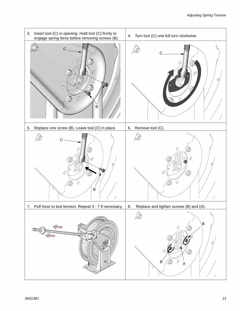
3. Insert tool (C) in opening. Hold tool (C) firmly to engage spring force before removing screws (B).
4. Turn tool (C) one full turn clockwise.
5. Replace one screw (B). Leave tool (C) in place. 6. Remove tool (C).
7. Pull hose to test tension. Repeat 3 - 7 if necessary. 8. Replace and tighten screws (B) and (A).if
B
C
B
C
B
C
B
B A

Adjusting Spring Tension
14 3A0138J
Decreasing Spring Tension
The spring is always under great tension, which if released in an uncontrolled manner could cause seri-ous injury.
• Never allow the reel to spin freely. Uncontrolled spinning could cause serious injury if you are hit by the hose.
• Always grasp the tool firmly with both hands when adjusting tension. Spring tension can cause the tool to move violently.
• The reel must be bolted securely in place when making adjustments.
1. Loosen (A) 3-5 turns. Do not remove (A)! 2. Loosen (B) 3-5 turns. Do not remove (B) yet.
3. Insert tool (C) in opening. Hold tool (C) firmly to engage spring force before removing screws (B).
4. Turn tool (C) one full turn counter-clockwise.
A
B

Adjusting Spring Tension
3A0138J 15
5. Replace one screw (B). Leave tool (C) in place. 6. Remove tool (C).
B
C
B
C
B
C

Adjusting Spring Tension
16 3A0138J
7. Pull hose to test tension. Repeat 3 - 7 if necessary. 8. Replace and tighten screws (B) and (A).if
B
BA

Hose Stopper Installation
3A0138J 17
Hose Stopper Installation
Installing Meter
1. 2.
ti13525
1.

Parts: HS Models
18 3A0138J
Parts: HS Models (For a complete list of model numbers, see page 3)
Ref. No. Part No. Description Qty1‡ SHAFT, spring (not shown) 12 15Y781 WASHER, flat (not shown) 13† SHAFT, swivel, (HSLC8,
HSMC8,HSLD5, HSLE3, HSMD5 and HSMDD models)
1
4‡ KEY, square (not shown) 16‡ BEARING, needle, swivel side (not
shown)1
7‡ WASHER, flat, spring side 18‡ BEARING, needle, spring side (not
shown)1
9‡ FLANGE, set, black 110‡ SPRING, power, 21 turn (not
shown)1
11‡ COVER, spring, black (not shown) 112‡ GASKET (not shown) 114 15Y122 ADJUSTER, power spring 115 277867 WASHER, flat, square center 116 15U581 WASHER, flat 31 id 117 16A719 WASHER, flat 118 278151 SCREW, swivel shaft 119 107100 SCREW, cap 220† PACKING, o-ring 221† RING, backup I 222† SWIVEL, elbow (HSLC8, HSMC8
models1
SWIVEL, elbow (HSLD5, HSLE3, HSMD5, and HSMDD models
1
23 155470 FITTING, swivel, union (HSHC5, HSLC8, HSHCD, HSMC8, HSPC5 models)
1
160327 FITTING, swivel, union (HSLD5, HSLE3, HSMD5, and HSMDD models
1
161037 FITTING, swivel, union (HSHFF, HSPB8, HSHB7 models)
1
24 16A146 BASE, painted, all models white 116A147 BASE, painted, all models metallic
blue1
16A148 BASE, painted, all models yellow 116A149 BASE, painted, all models desert
sand1
25 15U448 RING, retaining, ext, 22mm 126 16A134 PEDESTAL, arm, swivel side, all
models white1
16A135 PEDESTAL, arm, swivel side, all models metallic blue
1
16A136 PEDESTAL, arm, swivel side, all models, yellow
1
16A137 PEDESTAL, arm, swivel side, all models desert sand
1
27 16A691 SCREW, socket head 2
28 24C986 HOSE, coupled, 50 ft (HSHC5 models)
1
24C987 HOSE, coupled, 75 ft (HSLC8 mod-els)
1
24C988 HOSE, coupled, 50 ft (HSLD5 mod-els)
1
24C989 HOSE, coupled, 30 ft (HSLE3 mod-els)
1
24C990 HOSE, coupled, 75 ft (HSMC8 models)
1
24C991 HOSE, coupled, 50 ft (HSMD5 models)
1
24C992 HOSE, coupled, 75 ft (HSPB8 mod-els)
1
126076 HOSE, coupled, 75 ft (HSHB7 models)
1
126075 HOSE, coupled, 50 ft (HSPC5 models)
1
30 16A121 ARM, guide, all models, white 216A122 ARM, guide, all models, metallic
blue2
16A123 ARM, guide, all models, yellow 216A124 ARM, guide, all models, desert
sand2
31 16A140 GUIDE, hose, all models, white 116A141 GUIDE, hose, all models, metallic
blue1
16A142 GUIDE, hose, all models, yellow 116A143 GUIDE, hose, all models, desert
sand1
32 186580 NUT, hex (HSHC5, HSHCF, HSLC8, HSMC, HSPB8, HSPC5, HSHB7 models)
1
15Y905 NUT, hex (HSLD5, HSLE3, HSMD5, and HSMDD models)
33 104541 NUT, lock 834 BRACKET, roller 135 PIN, roller 236 BOLT, m6x 20 lg w/patch 437 ROLLER, hose 238 PIN, roller 239 ROLLER, hose 240 NUT, lock, hex 141 BUSHING, pawl (not shown) 142 KIT, pawl, ratchet 143 BOLT, m10 x 40 lg 144 SPRING, sst 146 15W036 LABEL, Warning 148 SCREW, button head m6 449 218341 STOP, hose (HSHC5, HSLC8,
HSMC8, HSPB8, HSHB7, HSPC5 models)
2
Ref. No. Part No. Description Qty

Parts: HS Models
3A0138J 19
237873 STOP, hose (HSLD5 and HSMD5 models)
2
237874 STOP, hose (HSLE3 models) 250 SCREW, mach, phil, pn hd 251 NUT, hex, jam 252 111799 SCREW, cap, hex hd 653 16A390 NUT, hex 659 RATCHET, Aluminum 160## ASSEMBLY, high pressure swivel
(HSHC5, HSHFF, HSPB8, HSHCD, HSHB7, HSPC5)
1
Replacement Danger and Warning labels, tags and cards are available at no cost.
† Included in Low / Medium Pressure Swivel and Seal Replacement Kit 24C993 - 1/2” NPSM, 24P059 - 1/2” BSPT, or 24C994 - 3/4” NPSM, 24P060 - 3/4” BSPT
Included in Ratchet and Latch Replacement Kit 24C995
Included in Hose Guide Kit 24C996 Included in Bulk Head Hose Guide Kit 24C997‡ Included in Spool Replacement Kit 24C998 Included in Hose Stop Replacement Kit 218341,
237873 or 237874 Included in Low / Medium Pressure Swivel Seal
Replacement Kit 24D134## Included in High Pressure Swivel Assembly Kit
128920 - 1/2” NPSM, 128921 - 1/2” BSPT
Ref. No. Part No. Description Qty

Parts: HS Models
20 3A0138J
50
51
49
39
38
37
35
36
34
31
52
53
5330
30
52
23
48 59
44
33
28
42
43
4046 19
24
321
2026
27
7
16
2515
32
17
18
14
9
22
Low/MediumPressureReels Only
High Pressure ReelsOnly
60

Parts: HN Models
3A0138J 21
Parts: HN Models (For a complete list of model numbers, see page 4)
Ref. No. Part No. Description Qty1‡ SHAFT, spring (not shown) 12 15Y781 WASHER, flat (not shown) 13† SWIVEL, shaft (HNLC8,
HNMC8,HNLD5, HNLE3, HNMD5 and HNMDD)
1
4‡ KEY, square (not shown) 16‡ BEARING, needle, swivel side (not
shown)1
7‡ WASHER, flat, spring side 18‡ BEARING, needle, spring side (not
shown)1
9‡ FLANGE, set, black 110‡ SPRING, power, 21 turn (not
shown)1
11‡ COVER, spring, black (not shown) 112‡ GASKET (not shown) 114 15Y122 ADJUSTER, power spring 115 277867 WASHER, flat, square center 116 15U581 WASHER, flat 31 id 117 16A719 WASHER, flat 118 278151 SCREW, swivel shaft 119 107100 SCREW, cap 220† PACKING, o-ring 221† RING, backup I 222† SWIVEL, elbow 123 155470 FITTING, swivel, union (HNHC5,
HNLC8, HNMC8, HNHCD, HNPC5 models)
1
160327 FITTING, swivel, union (HNLD5, HNLE3, HNMD5, and HNMDD models
1
161037 FITTING, swivel, union (HNFFA, HNPB8, HNHB7 models)
1
24 16A146 BASE, painted, all models white 116A147 BASE, painted, all models metallic
blue1
16A148 BASE, painted, all models yellow 116A149 BASE, painted, all models desert
sand1
25 15U448 RING, retaining, ext, 22mm 126 16A134 PEDESTAL, arm, swivel side, all
models white1
16A135 PEDESTAL, arm, swivel side, all models metallic blue
1
16A136 PEDESTAL, arm, swivel side, all models, yellow
1
16A137 PEDESTAL, arm, swivel side, all models desert sand
1
27 16A691 SCREW, socket head 228 24C986 HOSE, coupled, 50 ft (HNHC5
models)1
126076 HOSE, coupled, 75 ft (HNHB7 models)
1
126075 HOSE, coupled, 50 ft (HNPC5 models)
24C987 HOSE, coupled, 75 ft (HNLC8 mod-els)
1
24C988 HOSE, coupled, 50 ft (HNLD5 mod-els)
1
24C989 HOSE, coupled, 30 ft (HNLE3 mod-els)
1
24C990 HOSE, coupled, 75 ft (HNMC8 models)
1
24C991 HOSE, coupled, 50 ft (HNMD5 models)
1
24C992 HOSE, coupled, 75 ft (HNPB8 models)
1
32 186580 NUT, hex (HNHC5, HNHCF, HNLC8, HNSMC,8, HNPB8, HNPC5, HNHB7 models)
1
15Y905 NUT, hex (HNLD5, HNLE3, HNMD5, and HNMDD models)
33 104541 NUT, lock 840 NUT, lock, hex (not shown) 141 BUSHING, pawl (not shown) 142 KIT, pawl, ratchet 143 BOLT, m10 x 40 lg 144 SPRING, sst 146 15W036 LABEL, Warning 148 SCREW, button head m6 449 218341 STOP, hose (HNHC5, HNLC8,
HNMC8, HNPB8, HNPC5, HNHB7 models)
2
237873 STOP, hose (HNLD5 and HNMD5 models)
2
237874 STOP, hose (HNLE3 models) 250 SCREW, mach, phil, pn hd 251 NUT, hex, jam 259 RATCHET, Aluminum 160## ASSEMBLY, high pressure swivel
(HSHC5, HSHFF, HSPB8, HSHCD, HSHB7, HSPC5)
1
Replacement Danger and Warning labels, tags and cards are available at no cost.
† Included in Low / Medium Pressure Swivel and Seal Replacement Kit 24C993 - 1/2”, 24C994 - 3/4”
Ref. No. Part No. Description Qty

Parts: HN Models
22 3A0138J
Hose Inlet Kits
Included in Ratchet and Latch Replacement Kit 24C995
‡ Included in Spool Replacement Kit 24C998 Included in Hose Stop Replacement Kit 218341,
237873 or 237874
Ref. No. Part No. Description Qty
Included in Low ? Medium Pressure Swivel Seal Replacement Kit 24D134
## Included in High Pressure Swivel Assembly Kit 128920
Ref. No. Part No. Description Qty
50
51
49
53
23
48 59
44
28
42
43
19
24
321
20
26
27
7
16
25
15
32
17
18
14
9
22
46Low/MediumPressure ReelsOnly
High Pressure Reels
60
Only
Part No.
Max Working Pressure Hose I.D.
Hose InletHose Length
Fittingpsi bar inch mm inch mm218549 2000 137
0.5 12npt(m) 24 610
90° swivel union24E283 5000 34524E284 1250 86 0.75 19
90° union24E285 125 8.6 1.0 25

Technical Data
3A0138J 23
Technical Data
Model No. Application Hose SizeMaximum Pressure Inlet
(NPSM)Outlet (NPT)PSI Bar Mpa
HSHC5#HNHC5#
Grease1/2 in. x 50 ft.(12.7 mm x 1524 cm)
5000 345 34.5 1/2 inch 1/2 inch
HSHFF#HNHFF#
Bare N/A 5000 345 34.5 1/2 inch 3/8 inch
HSLC8#HNLC8#
Air / Water1/2 in. x 80 ft.(12.7 mm x 2438.4 cm)
300 20.7 2.07 1/2 inch 1/2 inch
HSLD5#HNLD5#
Air / Water3/4 in. x 50 ft.(19.05 mm x 1524 cm)
300 20.7 2.07 3/4 inch 3/4 inch
HSLE3#HNLE3#
Fuel/Evacua-tion
1 in. x 30 ft.(25.4 mm x 914.4 cm)
125 8.6 0.86 3/4 inch 1 inch
HSMC8#HNMC8#
Oil1/2 in. x 80 ft.(12.7 mm x 2338.4 cm)
1500 103.4 10.34 1/2 inch 1/2 inch
HSMD5#HNMD5#
Oil3/4 in. x 50 ft.(19.05 mm x 1524 cm)
1250 86 86.0 3/4 inch 3/4 inch
HSMDD#HNMDD#
Bare NA 2000 138 13.8 3/4 inch 3/4 inch
HSPB8#HNPB8#
Pressure Washer
3/8 in. x 80 ft.(9.5 mm x 2438.4 cm)
4000 275 27.5 1/2 inch 3/8 inch
HSHCD#HNHCD#
Bare NA 5000 345 34.5 1/2 inch 1/2 inch
HSMCF#HNMCF#
Bare NA 2000 138 13.8 1/2 inch 1/2 inch
HSHB7#HNHB7#
Grease3/8 x 75 ft(9.5 mm x 2286 cm)
5000 345 34.5 1/2 inch 3/8 inch
HSPC5#HNPC5#
Air / Water1/2 x 50 ft(12.7 mm x 1524 cm)
4500 310 31.0 1/2 inch 1/2 inch
Maximum Dry Weight (without hose)HS Models: 98 pounds (44.5 kg)HN Models: 64 pounds (29.0 kg)
Sound Data all models: Sound Pressure - 85.8 dB(A) calculated at 1 meter per ISO9614.2Sound Power - 94.9 dB(A) measured per ISO 9614-2
Wetted Parts
Models: HSL, HSM, HNL, and HNM
Nickel Plated Carbon Steel, Aluminum, Buna N Rubber, UHMWPE
Models: HSH, HSP, HNH, and HNP
Nickel Plated Stainless Steel, Buna N Rubber, UHMWPE
Technical Data
24 3A0138J
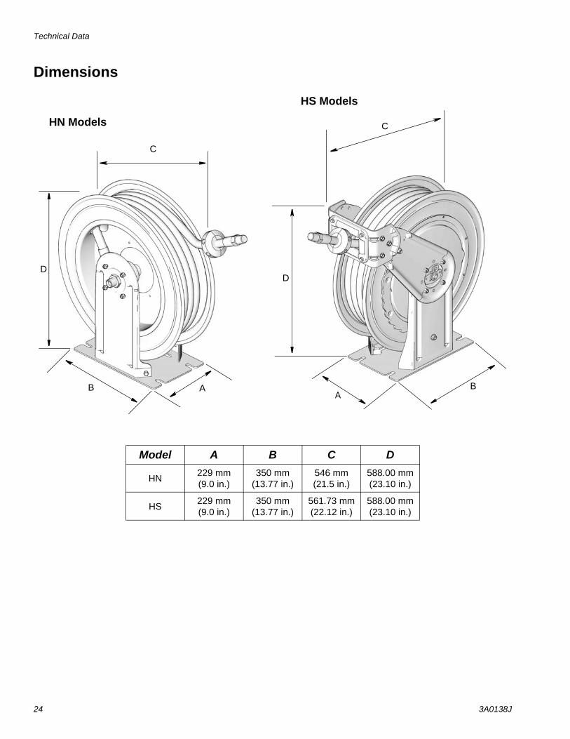
Dimensions
Model A B C D
HN 229 mm(9.0 in.)
350 mm(13.77 in.)
546 mm(21.5 in.)
588.00 mm(23.10 in.)
HS229 mm(9.0 in.)
350 mm(13.77 in.)
561.73 mm(22.12 in.)
588.00 mm(23.10 in.)
AB
C
D
C
D
B A
HN Models
HS Models

Technical Data
3A0138J 25
Mounting Pattern
293.86 mm
131.76 mm(5.187 in.)
14 mm (1/2 in.)bolts - 4X
(11.57 in.)

Graco reserves the right to make changes at any time without notice.
For patent information, see www.graco.com/patents.
Original instructions. This manual contains English. MM 3A0138
Graco Headquarters: MinneapolisInternational Offices: Belgium, China, Japan, Korea
GRACO INC. AND SUBSIDIARIES • P.O. BOX 1441 • MINNEAPOLIS MN 55440-1441 • USA
Copyright 2009, Graco Inc. All Graco manufacturing locations are registered to ISO 9001.www.graco.com
Revised May 2016
Graco 7-Year Hose Reel WarrantyGraco warrants all equipment referenced in this document which is manufactured by Graco and bearing its name to be free from defects in material and workmanship on the date of sale to the original purchaser for use. With the exception of any special, extended, or limited warranty published by Graco, Graco will, for a period from the date of sale as defined in the table below from the date of sale, repair or replace equipment covered by this warranty and determined by Graco to be defective. This warranty applies only when the equipment is installed, operated and maintained in accordance with Graco’s written recommendations.
This warranty does not cover, and Graco shall not be liable for general wear and tear, or any malfunction, damage or wear caused by faulty installation, misapplication, abrasion, corrosion, inadequate or improper maintenance, negligence, accident, tampering, or substitution of non-Graco component parts. Nor shall Graco be liable for malfunction, damage or wear caused by the incompatibility of Graco equipment with structures, accessories, equipment or materials not supplied by Graco, or the improper design, manufacture, installation, operation or maintenance of structures, accessories, equipment or materials not supplied by Graco.
This warranty is conditioned upon the prepaid return of the equipment claimed to be defective to an authorized Graco distributor for verification of the claimed defect. If the claimed defect is verified, Graco will repair or replace free of charge any defective parts. The equipment will be returned to the original purchaser transportation prepaid. If inspection of the equipment does not disclose any defect in material or workmanship, repairs will be made at a reasonable charge, which charges may include the costs of parts, labor, and transportation.
THIS WARRANTY IS EXCLUSIVE, AND IS IN LIEU OF ANY OTHER WARRANTIES, EXPRESS OR IMPLIED, INCLUDING BUT NOT LIMITED TO WARRANTY OF MERCHANTABILITY OR WARRANTY OF FITNESS FOR A PARTICULAR PURPOSE.
Graco’s sole obligation and buyer’s sole remedy for any breach of warranty shall be as set forth above. The buyer agrees that no other remedy (including, but not limited to, incidental or consequential damages for lost profits, lost sales, injury to person or property, or any other incidental or consequential loss) shall be available. Any action for breach of warranty must be brought within one (1) year past the warranty period or two (2) years for all other parts.
GRACO MAKES NO WARRANTY, AND DISCLAIMS ALL IMPLIED WARRANTIES OF MERCHANTABILITY AND FITNESS FOR A PARTICULAR PURPOSE, IN CONNECTION WITH ACCESSORIES, EQUIPMENT, MATERIALS OR COMPONENTS SOLD BUT NOT MANUFACTURED BY GRACO. These items sold, but not manufactured by Graco (such as electric motors, switches, hose, etc.), are subject to the warranty, if any, of their manufacturer. Graco will provide purchaser with reasonable assistance in making any claim for breach of these warranties.
In no event will Graco be liable for indirect, incidental, special or consequential damages resulting from Graco supplying equipment hereunder, or the furnishing, performance, or use of any products or other goods sold hereto, whether due to a breach of contract, breach of warranty, the negligence of Graco, or otherwise.
FOR GRACO CANADA CUSTOMERSThe Parties acknowledge that they have required that the present document, as well as all documents, notices and legal proceedings entered into, given or instituted pursuant hereto or relating directly or indirectly hereto, be drawn up in English. Les parties reconnaissent avoir convenu que la rédaction du présente document sera en Anglais, ainsi que tous documents, avis et procédures judiciaires exécutés, donnés ou intentés, à la suite de ou en rapport, directement ou indirectement, avec les procédures concernées.
Graco Information For the latest information about Graco products, visit www.graco.com. TO PLACE AN ORDER, contact your Graco distributor or call to identify the nearest distributor.Phone: 612-623-6928 or Toll Free: 1-800-533-9655, Fax: 612-378-3590
Graco 7-Year Hose Reel Extended Warranty
Component Warranty Period
Structural Components 7 years
Power Spring 3 years
Wear Parts - including but not limited to hose, seals, swivel seats and roller guides 1 year
Bare reels - all components 1 year