instructor reference manual - airfrance … · afr b777-300er instructor reference ... circuit...
TRANSCRIPT
��������
������� �������
AFR B777-300ER
INSTRUCTOR REFERENCEMANUAL

������� �������
��������������
����������������������������
��������������
���������������
�������������������
�����������������
Buttons
Colours
�����������������
��������
Numeric Keypad
Slew Tool
Alphanumeric Keypad
Pop-Up Menu
��������������
���������������
���������������
��������������
�������������������������
��������
������� �������
��������������
��������
Active Airport Mode
Aircraft – North Up Mode
Aircraft – Heading Up Mode
User Mode
Map Control
������������
��������������������������
���������������������
��������������
�������������������������������
����������������
����������������
�����
��������������������
��������������
�����������������
�����������
��������������
�������������������������
��������
������� �������
���������������
�����������������
Profile View
List View
Operating a Lesson Plan
����
�����������������
���������������������
�����������������
������������
��������������������
�����������������
����������
��������������
Select by Identifier
Select by Airport/Runway Reference
�����������
������
��������������
��� ����
���!
��������
������� �������
����������"����
���������
���������������������������
����
�����������������
!������
!��������������
Windshear Profiles:
FAA 1 (LANDING)
FAA 1 (PRIOR TO V R)
FAA 1 (ROTATION)
FAA 2
FAA 3
FAA 4
NEUTRAL
THUNDERSTORM 1
THUNDERSTORM 2
THUNDERSTORM 3
THUNDERSTORM 4
THUNDERSTORM 5
THUNDERSTORM 6 (JFK)
FRONTAL 1 (TOKYO 1966)
FRONTAL 2 (LOGAN)
FRONTAL 3

��������
������� �������
���������������
����������������$��%�������
������������������
��������������������
Emergency
Fire Detected
Fire Suppression
Complete Power Loss
Hydraulic Power Loss
��������
������� �������
����������������������������
���������

��������
������� �������
��������������
EMERGENCY STOP Initiates an emergency stop:� Switches off all electric and hydraulic power to the
simulator, except maintenance intercom.� Emergency lighting comes on.� Simulator settles to access position.� Drawbridge lowers.� Maintenance Call is activated.
HYDRAULICS OFF Stops all pumps and removes hydraulic power fromthe motion system, causing it to settle automaticallyto the access position.
Audio Control Panel As aircraft panel. Channel selection is made from theCommunications page.
UP, DWN Control movement of the instructors seat.
Switches display mounted reading light on/off.
Controls reading light brightness (dim/bright)
��������
������� �������
���������������������
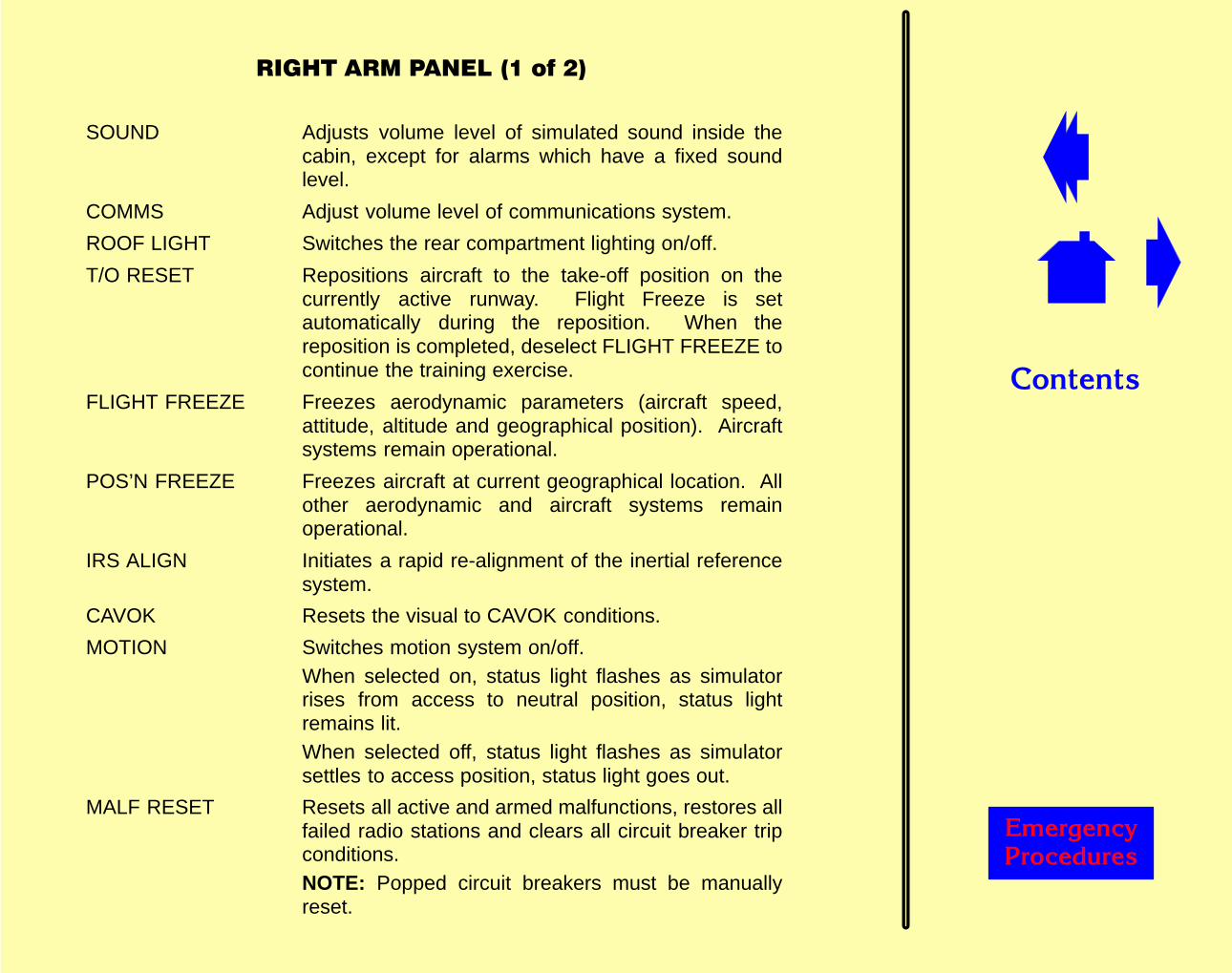
SOUND Adjusts volume level of simulated sound inside thecabin, except for alarms which have a fixed soundlevel.
COMMS Adjust volume level of communications system.
ROOF LIGHT Switches the rear compartment lighting on/off.
T/O RESET Repositions aircraft to the take-off position on thecurrently active runway. Flight Freeze is setautomatically during the reposition. When thereposition is completed, deselect FLIGHT FREEZE tocontinue the training exercise.
FLIGHT FREEZE Freezes aerodynamic parameters (aircraft speed,attitude, altitude and geographical position). Aircraftsystems remain operational.
POS’N FREEZE Freezes aircraft at current geographical location. Allother aerodynamic and aircraft systems remainoperational.
IRS ALIGN Initiates a rapid re-alignment of the inertial referencesystem.
CAVOK Resets the visual to CAVOK conditions.
MOTION Switches motion system on/off.When selected on, status light flashes as simulatorrises from access to neutral position, status lightremains lit.When selected off, status light flashes as simulatorsettles to access position, status light goes out.
MALF RESET Resets all active and armed malfunctions, restores allfailed radio stations and clears all circuit breaker tripconditions.NOTE: Popped circuit breakers must be manuallyreset.

��������
������� �������
����������������������
FUEL FREEZE Freezes fuel quantities at current value. Engine fuelflow is unaffected, but no fuel depletion occurs.
ENGINES START Starts all engines immediately, irrespective of air, fuel,oil or electrical supplies, provided the fuel cut–offswitches are in the flow position. Engines continue torun if fuel and oil supplies are available.
EXT POWER Simulates selection of an external power sourceprovided the aircraft is on the ground.
VISUAL ON/OFF Switches visual projectors on/off.
CONTROL LOADING Switches control loading system on/off.When selected on, hydraulic pressure is applied to thecontrols and status light flashes while flying controlsmove to their normal operating position. When systemis fully pressurised, status light remains lit.When selected off, hydraulic pressure is removed fromthe controls and status light flashes while flyingcontrols become slack. When system is fullyde-pressurised, status light goes out.

��������
������� �������
�������������������
��������
������� �������
�����������������������
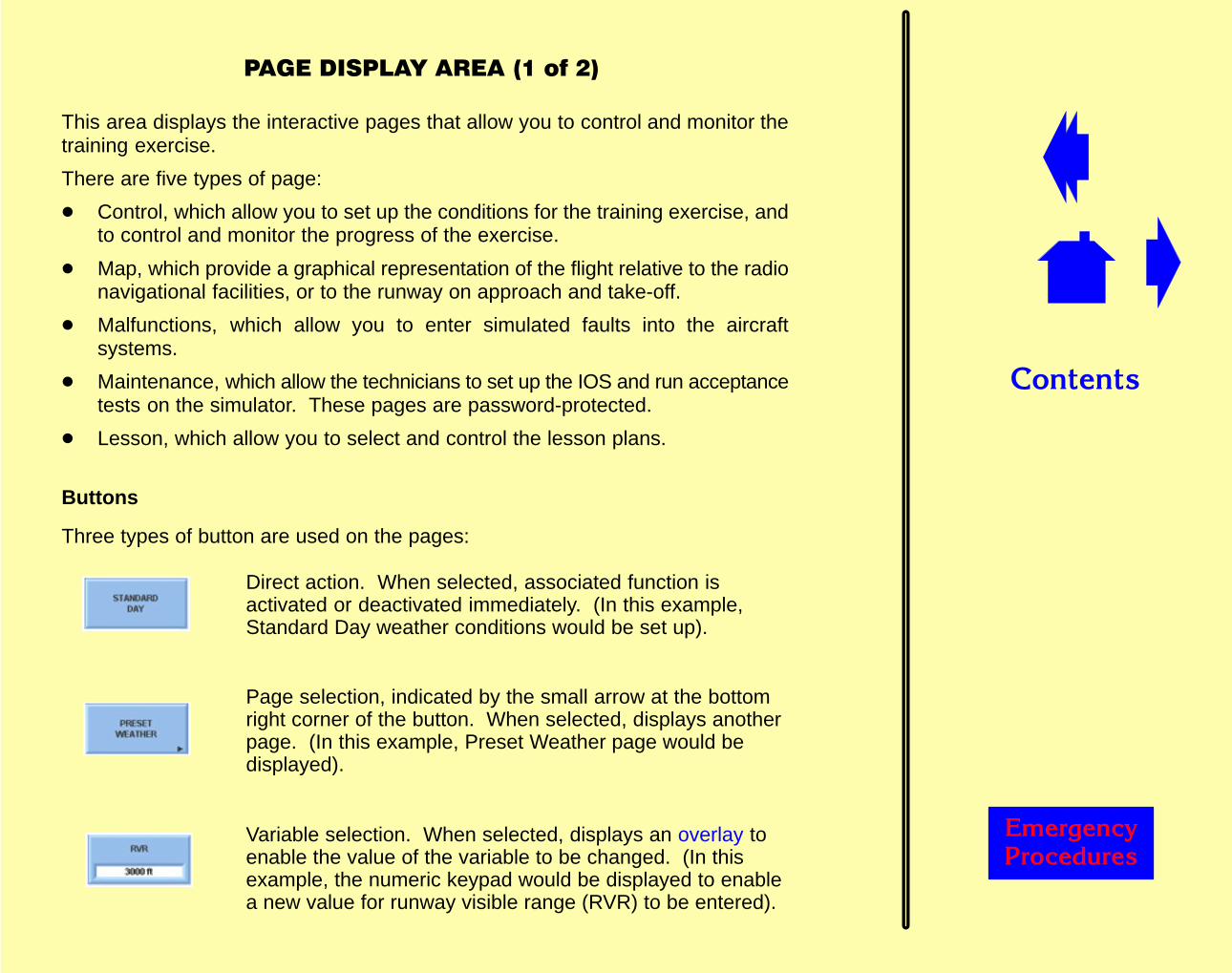
This area displays the interactive pages that allow you to control and monitor thetraining exercise.
There are five types of page:
� Control, which allow you to set up the conditions for the training exercise, andto control and monitor the progress of the exercise.
� Map, which provide a graphical representation of the flight relative to the radionavigational facilities, or to the runway on approach and take-off.
� Malfunctions, which allow you to enter simulated faults into the aircraftsystems.
� Maintenance, which allow the technicians to set up the IOS and run acceptancetests on the simulator. These pages are password-protected.
� Lesson, which allow you to select and control the lesson plans.
Buttons
Three types of button are used on the pages:
Direct action. When selected, associated function isactivated or deactivated immediately. (In this example,Standard Day weather conditions would be set up).
Page selection, indicated by the small arrow at the bottomright corner of the button. When selected, displays anotherpage. (In this example, Preset Weather page would bedisplayed).
Variable selection. When selected, displays an overlay toenable the value of the variable to be changed. (In thisexample, the numeric keypad would be displayed to enablea new value for runway visible range (RVR) to be entered).
��������
������� �������
������������������������
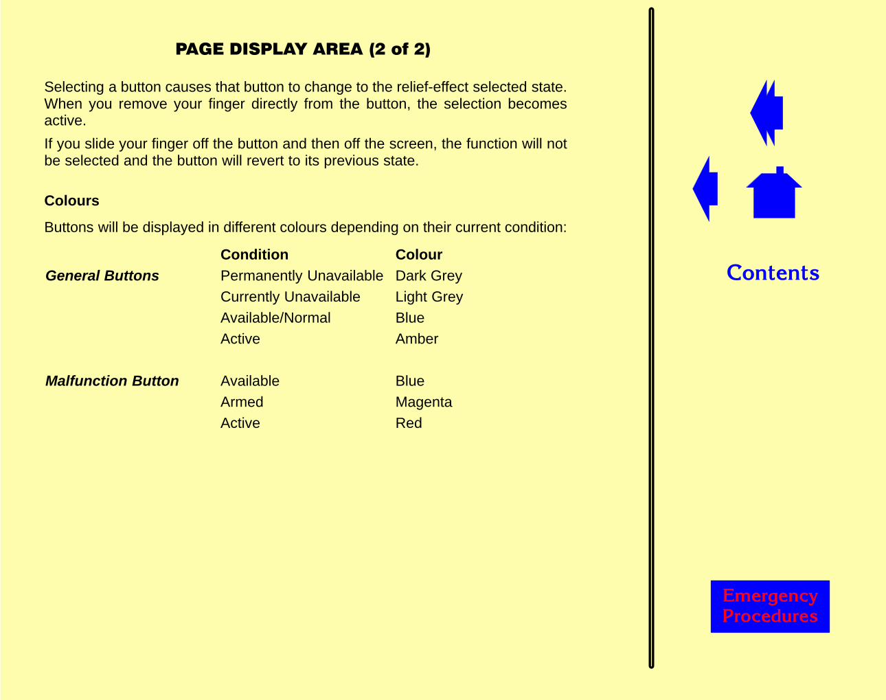
Selecting a button causes that button to change to the relief-effect selected state.When you remove your finger directly from the button, the selection becomesactive.
If you slide your finger off the button and then off the screen, the function will notbe selected and the button will revert to its previous state.
Colours
Buttons will be displayed in different colours depending on their current condition:
Condition ColourGeneral Buttons Permanently Unavailable Dark Grey
Currently Unavailable Light GreyAvailable/Normal BlueActive Amber
Malfunction Button Available BlueArmed MagentaActive Red
��������
������� �������
�����������������
The parameter readout displays the current status of a number of flight parameters(eg., altitude, heading), details of the currently active airport (ICAO code, runwayin use, ILS frequency), and also displays a dynamic readout showing messagesrelating to simulator status (eg., malfunction active, windshear selected, freezeselected).
This information is displayed on all pages, except:
� Plot pages
� Lesson pages
� Maintenance pages
� Area Map display (full screen)
� Circuit Breaker pages
� ECL Normal Checklist page
��������
������� �������
��������������
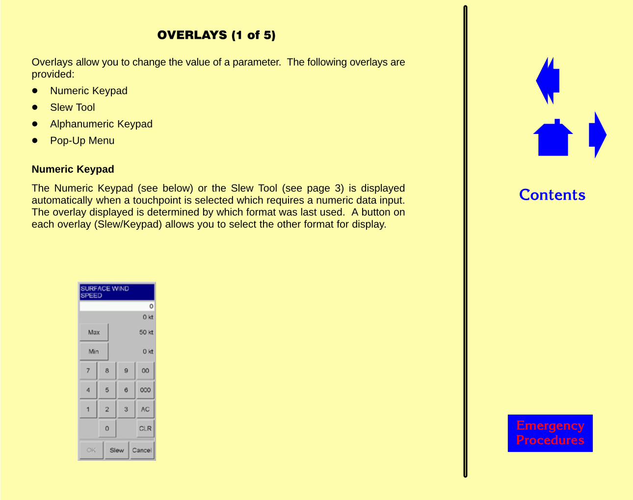
Overlays allow you to change the value of a parameter. The following overlays areprovided:
� Numeric Keypad
� Slew Tool
� Alphanumeric Keypad
� Pop-Up Menu
Numeric Keypad
The Numeric Keypad (see below) or the Slew Tool (see page 3) is displayedautomatically when a touchpoint is selected which requires a numeric data input.The overlay displayed is determined by which format was last used. A button oneach overlay (Slew/Keypad) allows you to select the other format for display.
��������
������� �������
���������������
The current value for the parameter is displayed on the overlay. Maximum andminimum values for the parameter are also displayed where appropriate.
The display line at the top of the overlay shows the value being entered. When youare satisfied with the entry, select OK and the new value will be entered into thesimulation. The overlay is removed from the display.
If you are not satisfied with the entry, select AC to clear the complete entry or selectCLR to clear the last input.
If you select Cancel, the overlay is removed from the display and the parameterreverts to its previous state.
When entering data, you will need to enter the figures exactly as required, exceptwhen entering heading values when the leading zeros are not required (030 can beentered as 30).
Latitude and longitude values can be entered as N, S, E or W in degrees, minutes,seconds and tenths of second (eg., N42�27’02.0”) (it is not necessary to type thedegrees, minutes and seconds symbols).
Latitude and longitude will be displayed on the IOS in degrees, minutes and tenthsof minutes, regardless of the format used to enter the values on the overlay. Forexample, a value entered as N42�27’30” will be displayed as N42�27.5.
If the selected parameter has pre-defined maximum and minimum limits, buttonsto select maximum and minimum are displayed.
If the entered value exceeds the maximum or minimum limits for the selectedparameter, the OK function is disabled and the entered value is displayed in red.
��������
������� �������
����������"����
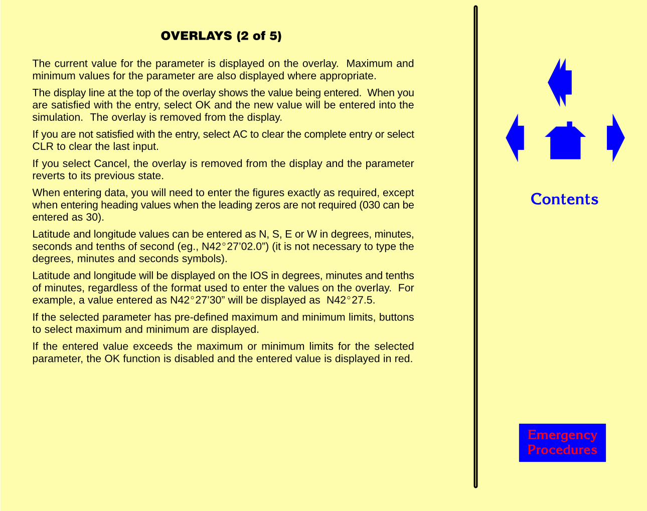
Slew Tool
The Slew Tool (see below) provides an alternative to the Numeric Keypad forentering numeric data when the selected parameter has maximum and minimumlimits. The Slew Tool is not available when editing latitude and longitude.
Two slider bars are provided: coarse, to set the value of the parameterapproximately to the required setting, and fine, to adjust the value to exactly theright setting.
To change the value of the parameter, use your finger to move the slider bar up ordown until the required value is achieved. Select OK to confirm the entry.

��������
������� �������
����������#����
Alphanumeric Keypad
The Alphanumeric Keypad (see below) is displayed automatically when atouchpoint is selected which requires an alphanumeric data input.
Two formats of the keypad are available: CDU and PC QWERTY. The formatdisplayed is determined by which format was last used. A button (PC/CDU) on thekeypad will allow you to select the other format.
The current entry is shown on the overlay. The display line at the top of the overlayshows the data being entered. When you are satisfied with the entry, select OK andthe new data will be entered into the simulation.
If you are not satisfied with the entry, select AC to clear the complete entry or selectCLR to clear the last input.
If you select Cancel, the overlay is removed from the display and the parameterreverts to its previous state.
��������
������� �������
���������������
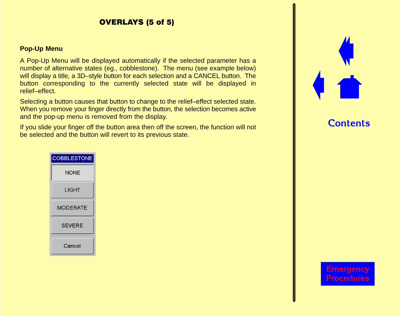
Pop-Up Menu
A Pop-Up Menu will be displayed automatically if the selected parameter has anumber of alternative states (eg., cobblestone). The menu (see example below)will display a title, a 3D–style button for each selection and a CANCEL button. Thebutton corresponding to the currently selected state will be displayed inrelief–effect.
Selecting a button causes that button to change to the relief–effect selected state.When you remove your finger directly from the button, the selection becomes activeand the pop-up menu is removed from the display.
If you slide your finger off the button area then off the screen, the function will notbe selected and the button will revert to its previous state.
��������
������� �������
�������������������"
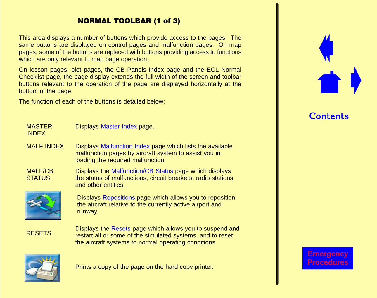
This area displays a number of buttons which provide access to the pages. Thesame buttons are displayed on control pages and malfunction pages. On mappages, some of the buttons are replaced with buttons providing access to functionswhich are only relevant to map page operation.
On lesson pages, plot pages, the CB Panels Index page and the ECL NormalChecklist page, the page display extends the full width of the screen and toolbarbuttons relevant to the operation of the page are displayed horizontally at thebottom of the page.
The function of each of the buttons is detailed below:
MASTERINDEX
Displays Master Index page.
MALF INDEX Displays Malfunction Index page which lists the availablemalfunction pages by aircraft system to assist you inloading the required malfunction.
MALF/CBSTATUS
Displays the Malfunction/CB Status page which displaysthe status of malfunctions, circuit breakers, radio stationsand other entities.
Displays Repositions page which allows you to repositionthe aircraft relative to the currently active airport andrunway.
RESETSDisplays the Resets page which allows you to suspend andrestart all or some of the simulated systems, and to resetthe aircraft systems to normal operating conditions.
Prints a copy of the page on the hard copy printer.
��������
������� �������
��������������������"
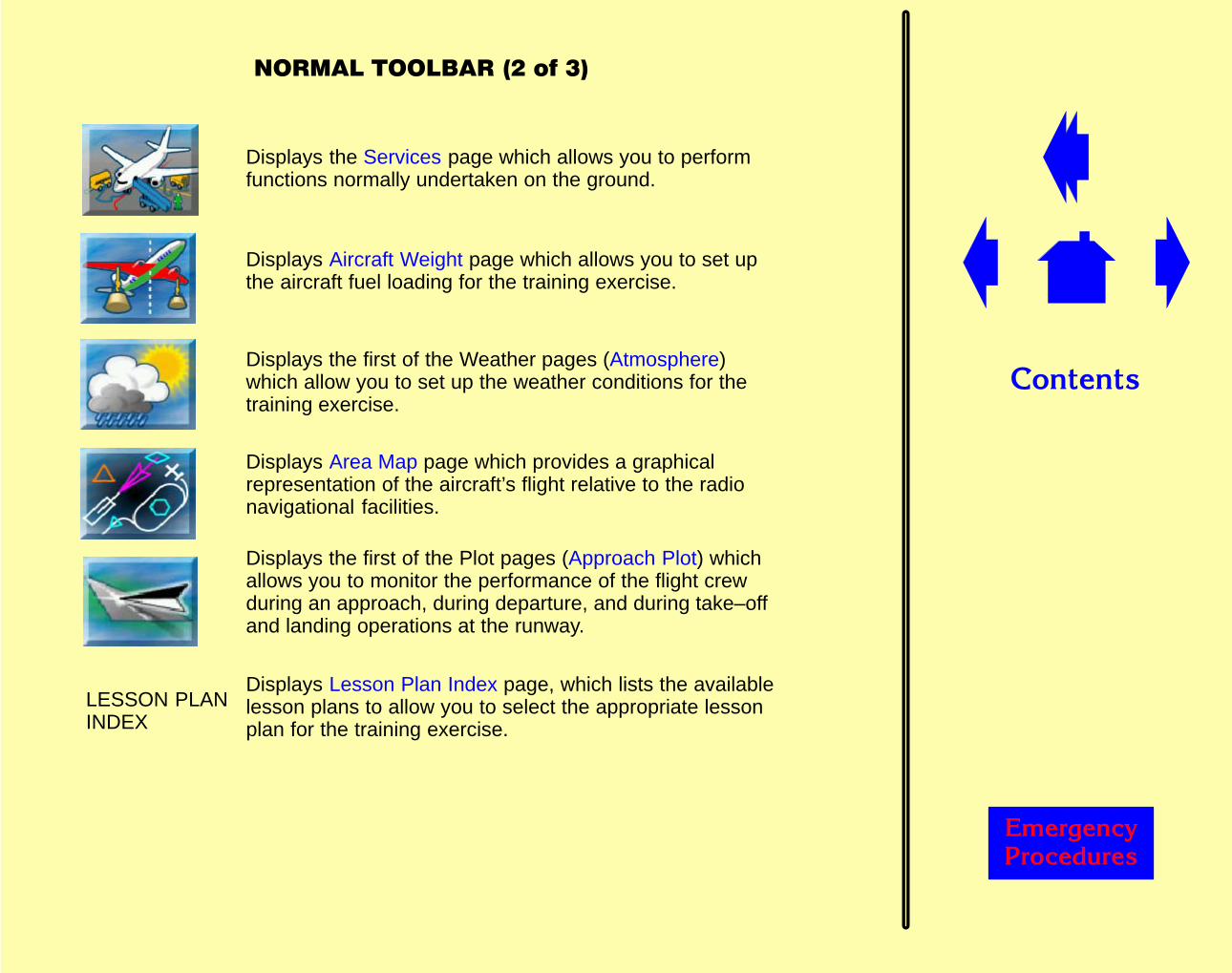
Displays the Services page which allows you to performfunctions normally undertaken on the ground.
Displays Aircraft Weight page which allows you to set upthe aircraft fuel loading for the training exercise.
Displays the first of the Weather pages (Atmosphere)which allow you to set up the weather conditions for thetraining exercise.
Displays Area Map page which provides a graphicalrepresentation of the aircraft’s flight relative to the radionavigational facilities.
Displays the first of the Plot pages (Approach Plot) whichallows you to monitor the performance of the flight crewduring an approach, during departure, and during take–offand landing operations at the runway.
LESSON PLANINDEX
Displays Lesson Plan Index page, which lists the availablelesson plans to allow you to select the appropriate lessonplan for the training exercise.

��������
������� �������
����������������"���"
Previous. Displays previous page in a suite of pages.
Return. Recalls last displayed page.Up to 31 of the previous page displays are retrievable.
Next. Displays next page in a suite of pages.
HELP Displays the Instructor Reference Manual page associatedwith the displayed page.
��������
������� �������
�������������
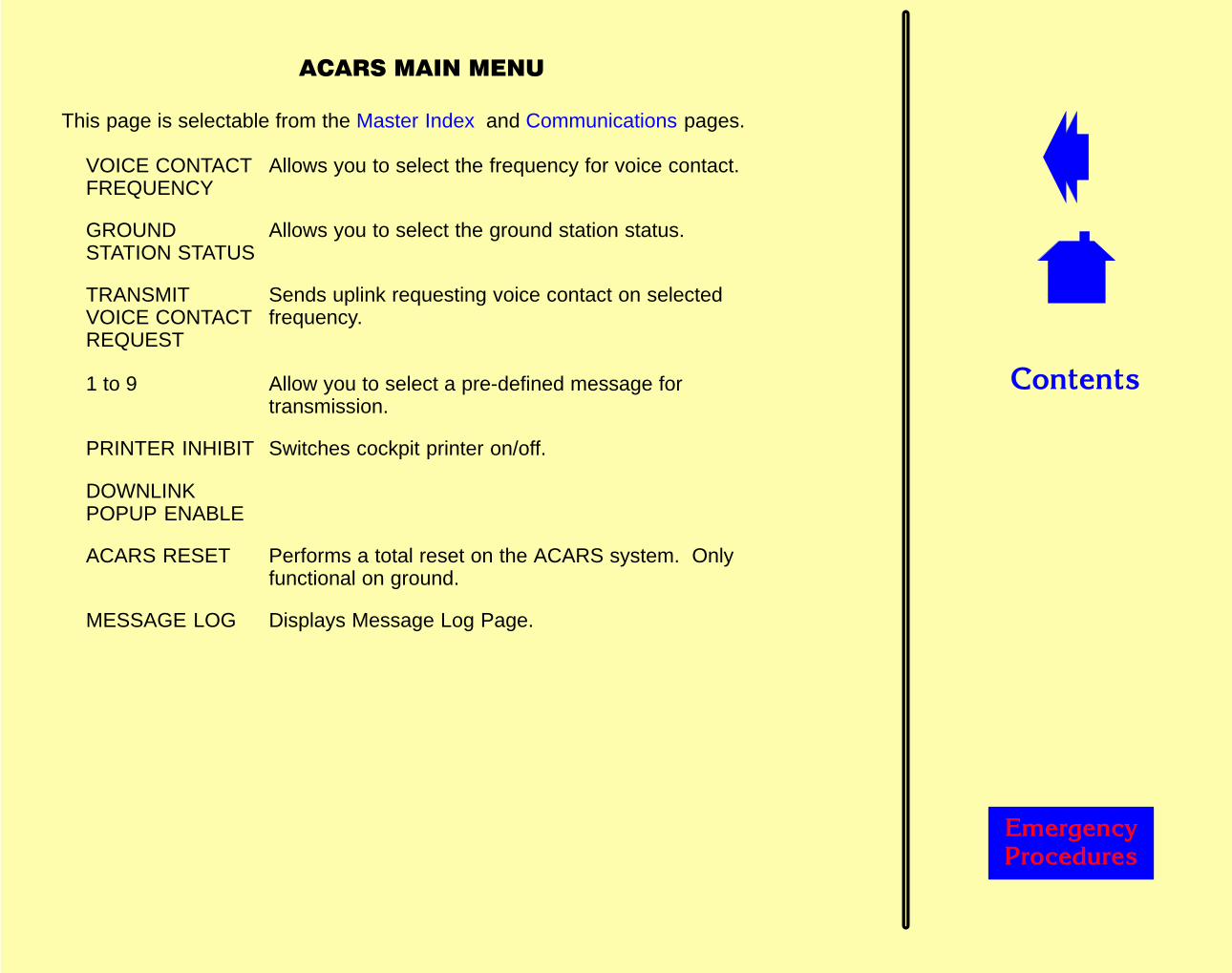
This page is selectable from the Master Index and Communications pages.
VOICE CONTACTFREQUENCY
Allows you to select the frequency for voice contact.
GROUNDSTATION STATUS
Allows you to select the ground station status.
TRANSMITVOICE CONTACTREQUEST
Sends uplink requesting voice contact on selectedfrequency.
1 to 9 Allow you to select a pre-defined message fortransmission.
PRINTER INHIBIT Switches cockpit printer on/off.
DOWNLINKPOPUP ENABLE
ACARS RESET Performs a total reset on the ACARS system. Onlyfunctional on ground.
MESSAGE LOG Displays Message Log Page.
��������
������� �������
�������������
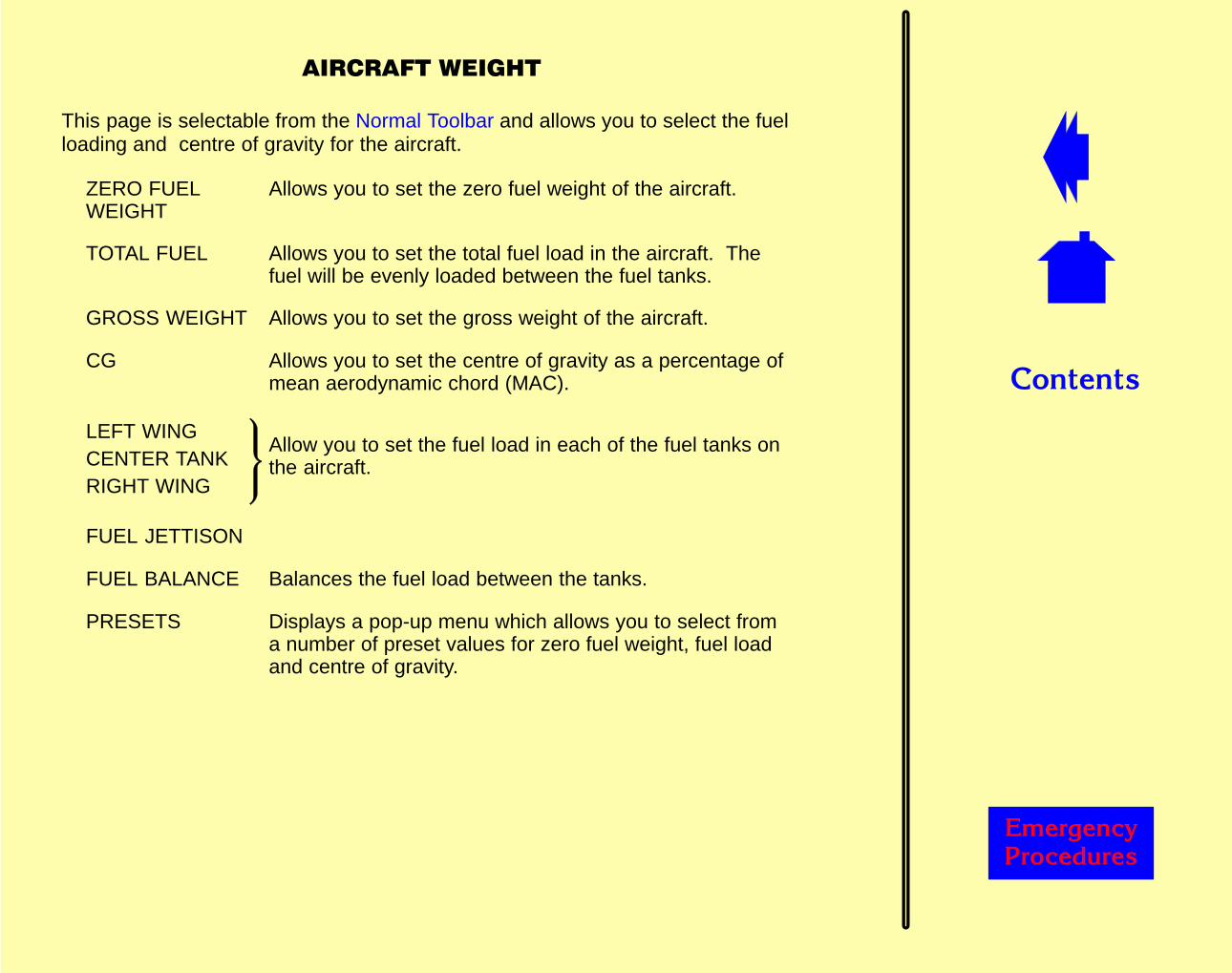
This page is selectable from the Normal Toolbar and allows you to select the fuelloading and centre of gravity for the aircraft.
ZERO FUELWEIGHT
Allows you to set the zero fuel weight of the aircraft.
TOTAL FUEL Allows you to set the total fuel load in the aircraft. Thefuel will be evenly loaded between the fuel tanks.
GROSS WEIGHT Allows you to set the gross weight of the aircraft.
CG Allows you to set the centre of gravity as a percentage ofmean aerodynamic chord (MAC).
LEFT WINGCENTER TANKRIGHT WING
Allow you to set the fuel load in each of the fuel tanks onthe aircraft.
FUEL JETTISON
FUEL BALANCE Balances the fuel load between the tanks.
PRESETS Displays a pop-up menu which allows you to select froma number of preset values for zero fuel weight, fuel loadand centre of gravity.

��������
������� �������
��������������
This page is selectable from a number of pages and allows you to change thecurrently active airport.
Geographic area touchpoints Display the associated Airport page which liststhe available airports within the geographicarea. Selecting one of the airports from the listchanges the active airport to that selected.
AIRPORT Displays the alphanumeric keypad to allow youto enter the ICAO code for the required airport.
����������������
������
�������������� ����������������
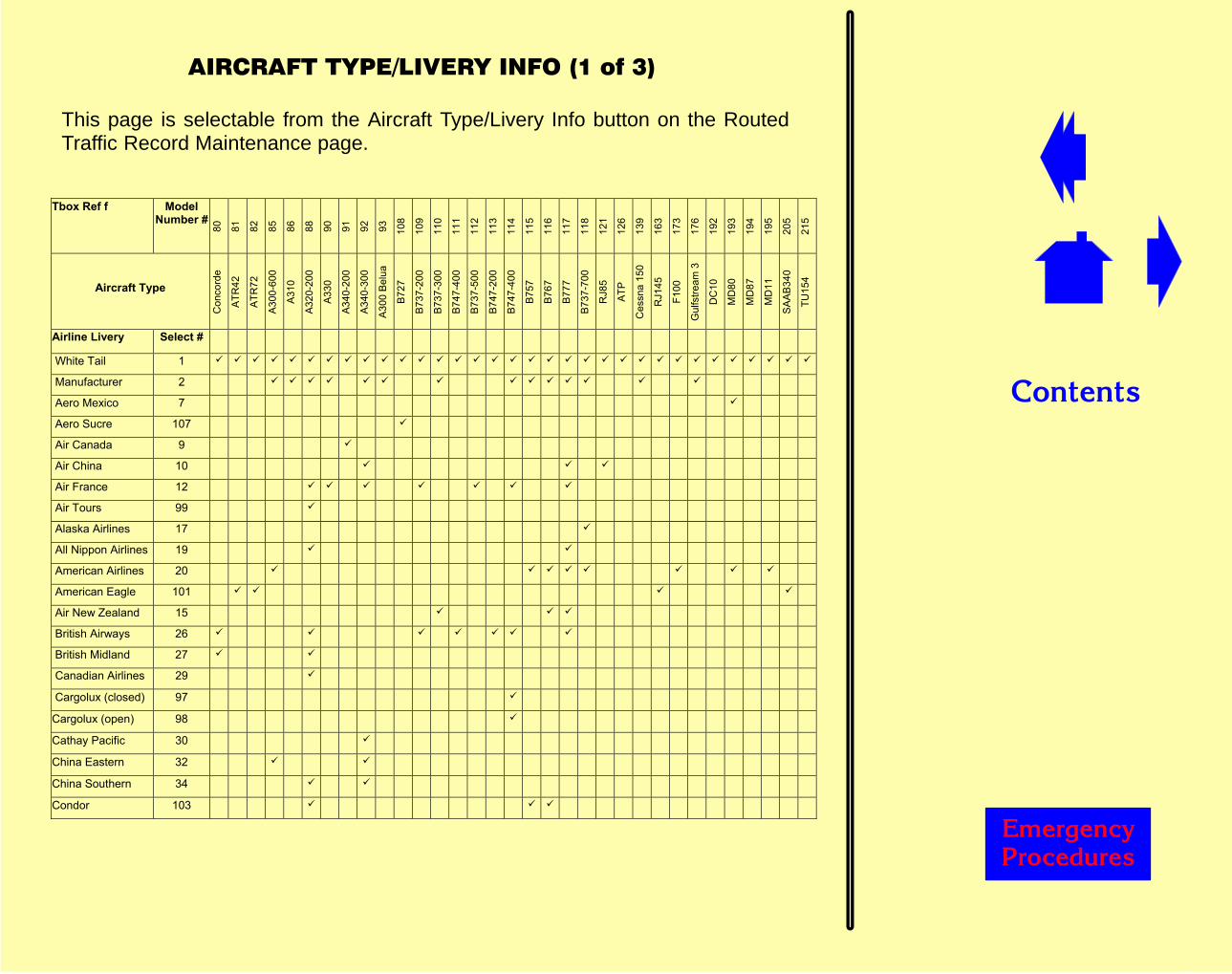
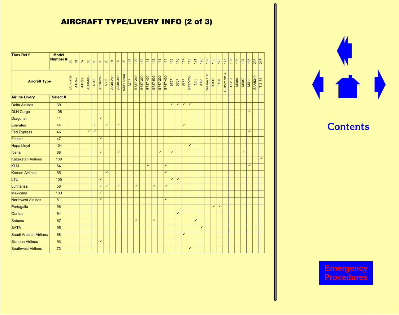
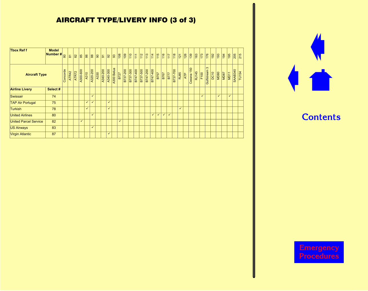
This page is selectable from the Aircraft Type/Livery Info button on the RoutedTraffic Record Maintenance page.
Tbox Ref f Model Number #
80
81
82
85
86
88
90
91
92
93
108
109
110
111
112
113
114
115
116
117
118
121
126
139
163
173
176
192
193
194
195
205
215
Aircraft Type
Con
cord
e
ATR
42
ATR
72
A30
0-60
0
A31
0
A32
0-20
0
A33
0
A34
0-20
0
A34
0-30
0
A30
0 B
elua
B72
7
B73
7-20
0
B73
7-30
0
B74
7-40
0
B73
7-50
0
B74
7-20
0
B74
7-40
0
B75
7
B76
7
B77
7
B73
7-70
0
RJ8
5
ATP
Ces
sna
150
RJ1
45
F100
Gul
fstre
am 3
DC
10
MD
80
MD
87
MD
11
SA
AB
340
TU15
4
Airline Livery Select #
White Tail 1
Manufacturer 2
Aero Mexico 7
Aero Sucre 107
Air Canada 9
Air China 10
Air France 12
Air Tours 99
Alaska Airlines 17
All Nippon Airlines 19
American Airlines 20
American Eagle 101
Air New Zealand 15
British Airways 26
British Midland 27
Canadian Airlines 29
Cargolux (closed) 97
Cargolux (open) 98
Cathay Pacific 30
China Eastern 32
China Southern 34
Condor 103
����������������
������
�������������� ����������������
Tbox Ref f Model Number #
80
81
82
85
86
88
90
91
92
93
108
109
110
111
112
113
114
115
116
117
118
121
126
139
163
173
176
192
193
194
195
205
215
Aircraft Type
Con
cord
e
ATR
42
ATR
72
A30
0-60
0
A31
0
A32
0-20
0
A33
0
A34
0-20
0
A34
0-30
0
A30
0 B
elua
B72
7
B73
7-20
0
B73
7-30
0
B74
7-40
0
B73
7-50
0
B74
7-20
0
B74
7-40
0
B75
7
B76
7
B77
7
B73
7-70
0
RJ8
5
ATP
Ces
sna
150
RJ1
45
F100
Gul
fstre
am 3
DC
10
MD
80
MD
87
MD
11
SA
AB
340
TU15
4
Airline Livery Select #
Delta Airlines 39
DLH Cargo 106
Dragonair 41
Emirates 44
Fed Express 46
Finnair 47
Hapa Lloyd 104
Iberia 88
Kazakstan Airlines 108
KLM 54
Korean Airlines 55
LTU 105
Lufthansa 58
Mexicana 100
Northwest Airlines 61
Portugalia 96
Qantas 64
Sabena 67
SATA 95
Saudi Arabian Airlines 68
Sichuan Airlines 93
Southwest Airlines 73
����������������
������
�������������� ����������������
Tbox Ref f Model Number #
80
81
82
85
86
88
90
91
92
93
108
109
110
111
112
113
114
115
116
117
118
121
126
139
163
173
176
192
193
194
195
205
215
Aircraft Type
Con
cord
e
ATR
42
ATR
72
A30
0-60
0
A31
0
A32
0-20
0
A33
0
A34
0-20
0
A34
0-30
0
A30
0 B
elua
B72
7
B73
7-20
0
B73
7-30
0
B74
7-40
0
B73
7-50
0
B74
7-20
0
B74
7-40
0
B75
7
B76
7
B77
7
B73
7-70
0
RJ8
5
ATP
Ces
sna
150
RJ1
45
F100
Gul
fstre
am 3
DC
10
MD
80
MD
87
MD
11
SA
AB
340
TU15
4
Airline Livery Select #
Swissair 74
TAP Air Portugal 75
Turkish 78
United Airlines 80
United Parcel Service 82
US Airways 83
Virgin Atlantic 87
��������
������� �������
�������������&
This page is selectable from the Normal Toolbar and displays the aircraft flight pathrelative to the airport and the navigational facilities in the area defined by the scaleof the map.
The following display modes are available:
� Active Airport
� Aircraft – North Up
� Aircraft – Heading Up
� User
Active Airport Mode
The map is centred on the currently active airport with true north at the top of thescreen.
The following elements can be displayed:
Colour Comments
NDB RadioNavigationStations
Green Normal. Displayed with appropriatesymbols, identification code andfrequency.
VHF RadioNavigationStations andwaypoints
Cyan
Magenta
Red
Normal. Displayed with appropriatesymbols, identification code andfrequency.
When stations are tuned.
Failed.
Airports(with ICAO code)
Grey Map centre airport.
��������
������� �������
��������������&
Aircraft track Red Last 16 minutes displayed.
Storm Green,Yellow,Amber, Red& Magenta
Outlines only when selected but notactive.
Full colour image when active. Coloursdepict storm reflectivity (intensity).
Snapshot Red Red “S” in a circle and snapshot number.
Microburst Magenta Location of microburst.
Windshear Magenta Location of active windshear.
Lat/Long grid White Displayed in steps of latitude andlongitude appropriate to the map range inuse.
Spider Web White Scaled appropriate to the map range inuse.
Aircraft location White Orientated to the true heading of theaircraft.
TCAS traffic If applicable. The relative altitude and avertical speed arrow (where applicable)are displayed for each traffic symbol.
Red square
Amber circle
Whitelozenge(solid)
Whitelozenge (wireframe)
Resolution advisory.
Traffic advisory.
Proximate traffic.
Out-of-range aircraft.
��������
������� �������
����������"���&
By default the following are only displayed when the map scale �20 nm:
Colour Comments
Outer markers
Middle markers
Inner markers
Yellow
Yellow
Yellow
ILS and LDA fans
Identification codeand frequency ofILS and LDA
Yellow
Yellow
Orientated to the true heading of thelocaliser beam.
Runways Grey Orientated to the true heading of therunway axis.
Identification codeof runway in use
Grey
The map range can be set to one of a number of preset values to maintain thepresent map centre and the current aircraft position on the map.
The aircraft track is shown as a line drawn from the centre towards the edge of thedisplay. As the edge of the display is reached, the scale of the map automaticallychanges to the next available. When the aircraft approaches the edge of the largestmap, the map mode changes automatically to Aircraft – North Up (with the aircraftat the centre).

��������
������� �������
����������#���&
Aircraft – North Up ModeThe map is centred on the aircraft with true north at the top of the screen. Thenavigational facilities move in relation to the aircraft and the track is shown as a lineleading backwards from the aircraft. All other features are the same as ActiveAirport Mode.
Aircraft – Heading Up ModeThe aircraft symbol is fixed at the mid-point between the centre and lower edge ofthe map with aircraft true heading at the top of the screen. The navigational facilitiesmove in relation to the aircraft. All other features are the same as Active AirportMode.
User ModeThis mode is accessed from the Radio Aids and Range Bearing icons on the MapToolbar, and reflects the fact that a feature (eg. a radio navigation aid) has beenselected as the map centre. All other display characteristics are as in Active AirportMode.
Map ControlWhen an Area Map is displayed, the Normal Toolbar is replaced by the Map Toolbarwhich allows you to control the map display.
MASTER INDEX Displays the Master Index page.
MALF INDEX Displays Malfunction Index page which lists the availablemalfunction pages by aircraft system to assist you inloading the required malfunction.
MALF/CB STATUS Displays Malfunction/CB Status page which lists all thecurrently active/armed malfunctions, tripped circuitbreakers and failed radio stations.
REPOSITIONS Displays Repositions page which allows you toreposition the aircraft relative to the currently activeairport and runway.
��������
������� �������
���������������
RESETS Displays the Resets page which allows you to suspendand restart all or some of the simulated systems, and toreset the aircraft systems to normal operating conditions.
HARD COPY Prints a copy of the area map.
MODE Displays the MODE keypad to allow the map displaymode to be changed. The mode defines the map centre.The currently selected mode is shown on the icon.The following options are available:� Active Airport� A/C North Up� A/C Heading UpA fourth mode, User, may be displayed and is selectedvia the Radio Aid or Range/Bearing buttons.
RANGE Displays RANGE keypad which allows the diameter ofthe map to be selected from a variety of options.If AUTO is selected, the range changes as the aircraftnears the edge of the map, maintaining the current mapcentre and ensuring the current aircraft position remainson the display.
FULL SCREEN Displays the map over the whole screen (page title,permanent readouts and toolbar are removed from thedisplay).Touching the screen again restores the display format tonormal.
DE-CLUTTER Displays the DECLUTTER keypad which allows you tocontrol the quantity and type of information shown on themap display.
��������
������� �������
����������'���&
RADIO AID When selected, a white circle and the SELECTSTATION ON MAP keypad are displayed. Touch theArea Map display to move the white circle to an area ofinterest, then use the keypad to select the requiredfacility.When a facility has been successfully selected, apop–up menu is displayed to allow you to:� Display station information� Fail/restore the facility� Display range/bearing information� Set the facility as the map centreSelecting range/bearing displays the ident, bearing andrange of the facility in the map display title bar.
RANGE BEARING Allows you to determine the range and bearing to radiofacilities or a lat/long position. When selected, a whitesquare frame (centred at the map reference position)and the RANGE & BEARING keypad are displayed.Move the white square frame to select a lat/long positionand use the keypad to determine the range and bearing.
A/C SLEW Displays the A/C SLEW keypad which allows you tochange the geographical position, speed, heading andaltitude of the aircraft.
WIND SLEW Allows you to change the wind speed and direction.When selected, a white circle with a projecting arrow andthe SURFACE WIND SLEW keypad are displayed.Touch the area map display to change the wind speedand direction. The keypad readouts and the size anddirection of the arrow will change accordingly. Select OKon the keypad to confirm the selection.
STORM SELECT Displays the Storm Select toolbar in place of the Maptoolbar.
��������
������� �������
����������&���&
SELECT STATION ON MAP
This popup is displayed when RADIO AID is selected on the Map Toolbar.
APTRWYILSMKRVHF loVHF hiNDBAWY MKR
Allow the associated facilities to be displayed/hiddenduring station selection. Refer to Declutter for adescription of each station type.
Zoom In Steps down through the map ranges with each selection.
Zoom Out Steps up through the map ranges with each selection.
OK Displays a menu of details for the radio station within thearea of interest defined by the white circle. If more thanone radio station is within the selected area, a pop–upmenu will be displayed listing the stations available. Themenu of details will be displayed for the radio stationchosen from this list. “Nothing Found” will be displayedif there are no stations within the selected area ofinterest.
Enter Ident Displays the alphanumeric keypad to allow a facility tobe selected by its ident.
Cancel Removes the keypad from the display.
��������
������� �������
����������(���&
RANGE & BEARING
This popup is displayed when SELECT BEARING is selected on the Map Toolbar.
Readouts Display current range and bearing to the radio facility orlat/long position selected by the white square frame.
Zoom In Steps down through the map ranges with each selection.
Zoom Out Steps up through the map ranges with each selection.
Brg/RngReference
Updates the range and bearing information in the mapdisplay title bar with the range and bearing to the facilityor lat/long position selected by the white square frame.
Set as map centre Causes the map to be redrawn with the facility or lat/longposition selected by the white square frame as the mapcentre.
Enter Ident Displays the alphanumeric keypad to allow a facility tobe selected by its ident. When a facility has beensuccessfully selected, a pop–up menu is displayed toallow you to:� Display station information� Fail/restore the facility� Display range/bearing information� Set the facility as the map centreSelecting range/bearing displays the ident, bearing andrange of the facility in the map display title bar.
Close Removes keypad from display.
��������
������� �������
����������)���&
DE-CLUTTER
This popup is displayed when DECLUTTER is selected on the Map Toolbar.
Auto Selects/deselects Auto mode.In Auto mode, the display of symbols is automaticallyand selectively controlled as the area covered increasesor decreases.In Manual mode, the display of the symbols is controlledby this keypad.
Freq Displays radio station broadcast frequency details.
APT Displays airport positions and ICAO codes, and enablesthe RWY button.
RWY Only operable when APT is selected on. Displays andidentifies airport runways, and enables ILS and MKRbuttons.
ILS Only operable when RWY is selected on. Indicateswhere runway ILS facilities exist.
MKR Only operable when RWY is selected on. Displayslocation of runway outer, middle and inner markerbeacons.
VHF lo Displays location of low-powered VHF stations.
VHF hi Displays location of high-powered VHF stations.
NDB Displays location of NDB stations.
��������
������� �������
����������*���&
DE-CLUTTER (continued)
AWY MKR Displays locations of airway marker beacons.
Approach Data Displays active runway identification and approach radiofacilities.
Snapshots Identifies locations where snapshots were taken.
TerminalWaypoints
Displays location of waypoints in the terminal area.
Enroute Waypoints Displays location of route waypoints incidental to theflight plan.
Storm Displays shape of selected storm model.
Web Overlays the display with a “spider web” (compass rose)with radials at 45° intervals and circles at full and halfrange from the centre, annotated in accordance with thecurrent display range. Mutually exclusive with Grid.
Grid Overlays the display with a latitude/longitude grid oflines, identified with their co-ordinates. The intervalbetween the lines varies with map range. Mutuallyexclusive with Web.
Track Displays a trace of the aircraft flight path.
Erase Track Momentary action. Deletes existing trace of aircraftflight path.
Close Removes keypad from display.
��������
������� �������
�������������&
A/C SLEW
This popup is displayed when A/C SLEW is selected on the Map Toolbar.
TARGET MODE These controls allow you to set target values for aircraftposition, speed, heading and altitude. When the targetis set, the associated parameter changes at a constantrate until the target is reached.
ON MAP Displays a white square frame (centred at the aircraftposition) and the POSITION SLEW keypad.Touch the Area Map display to move the white squareframe, or use the Enter Ident function, to set a targetvalue for aircraft position. Select OK to confirm yourchoice.
SPD Displays the numeric keypad to allow a target value forthe aircraft airspeed to be entered. Current value isdisplayed on the button.
HDG Displays a white circle with a projecting arrow (at themap centre), and the HEADING keypad.Touch the Area Map display to set the target value forthe aircraft heading. The size and direction of the arrowwill change accordingly. Select OK on the keypad toconfirm your selection.
ALT (AMSL) Displays the numeric keypad to allow a target value forthe aircraft altitude (above mean sea level) to beentered. Current value is displayed on the button.
CONTINUOUSMODE
These controls change the associated parametercontinuously while selected.

��������
������� �������
��������������&
A/C SLEW (continued)
FWDLEFTRIGHTAFT
Move the aircraft in the associated direction, relative toits current position.
NWES
Move the aircraft in the associated geographicaldirection.
LR
Slew the aircraft heading continuously left and right.
Close Removes the keypad from the display.
��������
������� �������
����������"���&
POSITION SLEW
This popup is displayed when ON MAP is selected on the A/C SLEW pop–up.
Readout Displays current geographical position of the aircraft.
Zoom In Steps down through the map ranges with each selection.
Zoom Out Steps up through the map ranges with each selection.
OK Used to confirm the position selected by the whitesquare frame as the target aircraft position.
Enter Ident Displays the alphanumeric keypad to allow a radiofacility to be selected by its ident. The position of facilitywill then be the target value for the aircraft position.
Cancel Removes the keypad from the display.
HEADING
This popup is displayed when HDG is selected on the A/C SLEW pop–up.
Readout Displays current aircraft heading.
Zoom In Steps down through the map ranges with each selection.
Zoom Out Steps up through the map ranges with each selection.
OK Used to confirm the heading selected by the white arrowas the target aircraft heading.
Cancel Removes the keypad from the display.

��������
������� �������
����������#���&
STORM CONTROL
This toolbar is selectable from the Map Toolbar and allows you to control and modifythe storm models.
The centre of the storm is positioned as follows:
Name Centre of Storm Height (ft)
STORM 1 14501STORM 2 17078STORM 3 8079STORM 4 17001COLD FRONT 1 15078COLD FRONT 2 5034SHOWERS 3077SQUALLS 15078SNOW 3077RAIN 5079
Above the cloud layer, the storm cloud itself exists with a size and shape based onthe selection made from the IOS.
There is computed turbulence both under and in the storm cloud, dependent on theposition of the aircraft within the storm area.
Rain and hail intensity are computed based on the position within the storm areaand the outside air temperature (visual is defocused based on these computedvalues). By default, there is no precipitation outside the storm area.
Thunder and lightning are present within the storm area and the frequency ofthunder and lightning is based on proximity to the centre of the storm.
��������
������� �������
��������������&
STORM CONTROL (continued)
A rainshaft is positioned under the centre of the storm.
Out of the window visibility is reduced to zero when approaching the rainshaft.
Ambient brightness levels are reduced again based on proximity to the centre ofthe storm.
Wet runway contamination is present when the storm is selected.
SELECT Displays the STORM SELECT keypad which shows theavailable storm models pictorially and dimensionally.When a storm is first selected, it is inactive and isdisplayed in outline form in its default position on theMap display, but it will not be shown on the weatherradar display.NOTE: It may be necessary to change the map range tomake the storm visible.
STATUS Activates/deactivates the selected storm model. Whena storm is activated, the complete image is displayed onthe Map display and the storm is shown on the weatherradar display.If the storm characteristics (position, rotation and drift)are changed, the button legend shows MODIFIED.Selecting the button activates the modified storm.
POSITION Displays a white square frame (at the centre of the stormmodel) and the STORM POSITION keypad.Touch the Area Map display to move the white squareframe, or use the Enter Ident function, to set a targetvalue for storm. Select OK on the keypad to confirmyour selection.
��������
������� �������
����������'���&
STORM CONTROL (continued)
ROTATION Displays a white circle with a projecting arrow (at thecentre of the storm model) and the STORM ROTATIONkeypad.Touch the Area Map display to change the rotation of thestorm. The arrow will move accordingly. Select OK onthe keypad to confirm your choice.
DRIFT Displays a white circle and arrowhead (at the mapcentre) and the STORM DRIFT keypad to allow you toselect the storm drift speed and direction.By touching the Area Map display, move the arrowheadaround the circle to select the direction, and away fromthe circle to select the speed. The size and direction ofthe arrow will change accordingly. Confirm the selectionby selecting OK on the keypad.
BRIGHTNESS Displays the STORM BRIGHTNESS keypad to allowyou to control the intensity of the storm image on theMap display. Select HIGH, MEDIUM or LOW.NOTE: The outline storm display is always shown atHIGH brightness.
MAP RANGE Displays the RANGE keypad which allows the diameterof the map to be selected manually or automatically. IfAUTO is selected, the range changes as the aircraftnears the edge of the map, maintaining the current mapcentre and ensuring the current aircraft position remainson the display.
MAP Re-displays the Map toolbar in place of the Storm Selecttoolbar.

��������
������� �������
����������&���&
STORM POSITION
This popup is displayed when POSITION is selected on the Storm Control Toolbar.
Readout Displays current geographical position of the storm.
Zoom In Steps down through the map ranges with each selection.
Zoom Out Steps up through the map ranges with each selection.
OK Used to confirm the position selected by the whitesquare frame as the storm position.
Enter Ident Displays the alphanumeric keypad to allow a radiofacility to be selected by its ident. The position of facilitywill then be the position of the storm.
Cancel Removes the keypad from the display.
STORM ROTATION
This popup is displayed when ROTATION is selected on the Storm Control Toolbar.
Readout Displays current storm rotation.
Zoom In Steps down through the map ranges with each selection.
Zoom Out Steps up through the map ranges with each selection.
OK Used to confirm the rotation selected by the white arrowas the storm rotation.
Cancel Removes the keypad from the display.
��������
������� �������
�����������������"
This page is selectable from the Master Index and Communications pages andallows you to manually control ATIS messages.
ATIS messages are automatically created for each airport according to the weatherconditions selected for the airport. When the conditions at the airport are changed,the associated ATIS message is automatically updated, and its information letteris incremented.
NOTE: The ATIS messages will be displayed in US format for all airports in theUSA and in ICAO format for all other airports.
To manually update an ATIS message:
� Select ATIS OVERRIDE which stops the ATIS message automaticallyupdating when the weather conditions for the airport change.
� Select AIRPORT, which displays Airport Select page.
� Select the airport where you want to update the ATIS message. ATIS page isredisplayed.
� The values of the parameters in the current ATIS message are displayed.
� Select the parameter you want to change and enter the new value.
The function of each touchpoint is described below:
AIRPORT Displays Airport Select page to allow you toselect the required airport.
RUNWAY IN USE Allows active runway to be changed for currentlyselected airport.
INFORMATION Indicates the information letter (revision level) ofthe ATIS message (A to K). Selecting the buttonallows you to select previous revisions of themessage for transmission.
��������
������� �������
������������������"
APPROACH TYPE Allows you to select the type of radio navigationstation used on approach.
ILS STATUS Allows you to select the type of failureassociated with the ILS on the currently activerunway
RUNWAY CONDITIONPRECIPVISIBILITY RESTRICTIONCLOUD 1 CONDITIONCLOUD 2 CONDITION
Allow the condition of the associated parameterto be changed.
GMTWIND DIRECTIONWIND SPEEDVISIBILITYCLOUD 1 HEIGHTCLOUD 2 HEIGHTTEMPDEWPOINTQNH (ICAO FORMAT ONLY)QFE (ICAO FORMAT ONLY)ALTIMETER (US FORMATONLY)
Allow the value of the associated parameter tobe changed.
��������
������� �������
��������������"���"
RVR:T/DOWNMIDFIELDROLLOUT
Allow the runway visual range (RVR) to be setfor the associated points on the runway.
RVR:INOP
Displays a pop-up menu, with selection optionsTDZ INOP, MIDFIELD INOP and ROLLOUTINOP, which allow you to suppress the broadcastof RVR information for the associated runwayarea.
SIGMET Displays significant meteorological information.
COMPL MESSAGE Displays Complementary ATIS Message page.
ATIS OVERRIDE Stops the ATIS message updating automaticallyto allow you to edit the message using thebuttons on the page.

��������
������� �������
��������������������������
This page is selectable from the ATIS Message Page. It provides a range ofmessages, one of which may be appended to the ATIS broadcast, normally toadvise of a situation (possibly a limitation or hazard) at the related airfield.
An ON/OFF control button is assigned to each message and is accompanied bya brief textual description of its content.
��������
������� �������
���������������
This page is selectable from the Master Index page and allows you to trip thesoftware controlled circuit breakers.
Each button on the page relates to a circuit breaker panel. Selecting a buttondisplays a page listing the software–controlled circuit breakers on that panel.Selecting a button on the page trips the associated circuit breaker.

��������
������� �������
�������������������"
This page is selectable from the Master Index and allows you to simulate radiocommunication between the ground and the flight crew.
SELCAL Initiates a SELCAL to the flight deck on the associatedchannel. The channels and currently tuned frequencyare displayed above the button.The call is cancelled:� when the flight crew acknowledge the call.� after 30 seconds if no acknowledgement is received.� by re-selecting the button.
CAPT, OBS, F/O Display the radio channel in use when the associatedflight crew member is transmitting. No display whenthere are no transmissions.
Ground Call:
GROUND TOFLIGHT DECK
Alerts the crew via a selcal ‘bong’ and an EICASmessage that there is an incoming maintenance callfrom the ground crew.
SATCOM VOICECALL
Alerts the crew via a selcal ‘bong’ and an EICASmessage that there is an incoming satcom commsrequest.
RT CHATTER Starts/stops radio chatter transmission.Chatter stops automatically when the instructor orflight crew transmit, and resumes two seconds afterthe end of the transmission.
��������
������� �������
��������������������"
Attendant Call:
ATTENDANTLOCATION
The display above the button indicates the stationcalled from the flight deck. No display when there isno transmission.Selecting this button displays a pop-up menu to allowyou to select the attendant location. When station isdisplayed above the button, select the equivalentstation to respond to the call from the flight deck.When no station is displayed, selecting an attendantlocation initiates a call from the ground crew to theflight deck. Chimes continue to sound until callacknowledged by flight crew, or self-cancel after 30seconds.
CABIN CALL Once selected a CABIN CALL SELECT pop–upappears allowing you to select from READY or ALERToptions.
COMM NOISE Allows you to set a level of noise interference on thecommunications channels.
Private Interphone:
CAPT, F/O Allow you to communicate directly with the flight crew.Once selected, the boomset of the associated crewmember is connected to your boomset in a separateaudio system, allowing direct communication betweenyou and the crew member. You do not need to use themic PTT as a hot mic system is active. While privateinterphone is active, other crew members can receiveand transmit as normal.

��������
������� �������
����������������"���"
SERVICEINTERPHONE
Switches flight interphone comms from the instructorsstation to ‘service interphone’ mode. The crew canonly communicate with the instructor using flightinterphone if the overhead panel service interphoneswitch is selected on. Normal crew flight interphoneoperation is unaffected.
COMMUNICATIONSMODE
Displays a pop–up menu to allow you to select thecommunications mode.
ACARS Display ACARS Main Menu page.
ATIS Displays ATIS page.
��������
������� �������
�������������������������������
This page is selectable from Master Index page and identifies those flying controlsnot in agreement with the current aircraft configuration.
��������
������� �������
����������������������
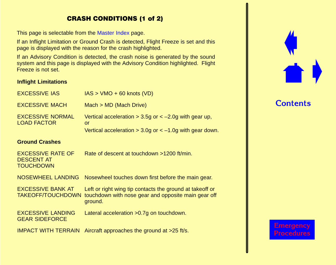
This page is selectable from the Master Index page.
If an Inflight Limitation or Ground Crash is detected, Flight Freeze is set and thispage is displayed with the reason for the crash highlighted.
If an Advisory Condition is detected, the crash noise is generated by the soundsystem and this page is displayed with the Advisory Condition highlighted. FlightFreeze is not set.
Inflight Limitations
EXCESSIVE IAS IAS > VMO + 60 knots (VD)
EXCESSIVE MACH Mach > MD (Mach Drive)
EXCESSIVE NORMALLOAD FACTOR
Vertical acceleration > 3.5g or < –2.0g with gear up,orVertical acceleration > 3.0g or < –1.0g with gear down.
Ground Crashes
EXCESSIVE RATE OFDESCENT ATTOUCHDOWN
Rate of descent at touchdown >1200 ft/min.
NOSEWHEEL LANDING Nosewheel touches down first before the main gear.
EXCESSIVE BANK ATTAKEOFF/TOUCHDOWN
Left or right wing tip contacts the ground at takeoff ortouchdown with nose gear and opposite main gear offground.
EXCESSIVE LANDINGGEAR SIDEFORCE
Lateral acceleration >0.7g on touchdown.
IMPACT WITH TERRAIN Aircraft approaches the ground at >25 ft/s.
��������
������� �������
�����������������������
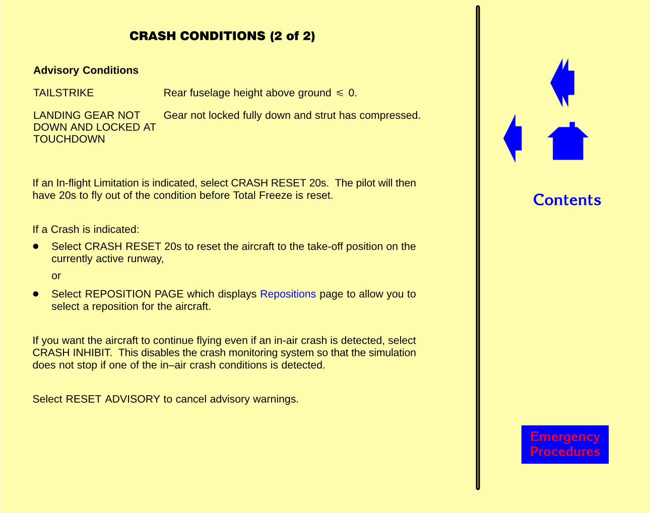
Advisory Conditions
TAILSTRIKE Rear fuselage height above ground � 0.
LANDING GEAR NOTDOWN AND LOCKED ATTOUCHDOWN
Gear not locked fully down and strut has compressed.
If an In-flight Limitation is indicated, select CRASH RESET 20s. The pilot will thenhave 20s to fly out of the condition before Total Freeze is reset.
If a Crash is indicated:
� Select CRASH RESET 20s to reset the aircraft to the take-off position on thecurrently active runway,
or
� Select REPOSITION PAGE which displays Repositions page to allow you toselect a reposition for the aircraft.
If you want the aircraft to continue flying even if an in-air crash is detected, selectCRASH INHIBIT. This disables the crash monitoring system so that the simulationdoes not stop if one of the in–air crash conditions is detected.
Select RESET ADVISORY to cancel advisory warnings.
��������
������� �������
����������������
This page is selectable from the Master Index page and allows you to recall setsof predefined configurations that are specific to particular customers.

��������
������� �������
�����
This page is selectable from the Services page and allows you to control the aircraftdoors.
FWD ACCESSENTRY 1LENTRY 2LENTRY 3LENTRY 4LENTRY 5LFWD CARGOE/E ACCESSENTRY 1RENTRY 2RENTRY 3RENTRY 4RAFT CARGOBULK CARGOENTRY 5R
Open/close associated door.
FDAS
DOOR LOCK STATUS Displays the current status of lockeddoors.
SLIDES TO MANUAL Arms/disarms operation of theemergency passenger slides.
OPEN SEQUENCE Opens doors in sequence.
CLOSE SEQUENCE Closes doors in sequence.
CLOSE ALL Closes all doors.
��������
������� �������
��������������������
The flight phase and the normal and non-normal checklists are automatically resetduring repositions as part of simsoft. These pages allow you to override the currentfight phase, and to reset the normal and non-normal checklists.
Three checklist pages are provided:
� ECL Normal Checklist
� ECL Non-normal Complete Checklist
� ECL Non-normal Incomplete Checklist
The ECL Normal Checklist page is selectable from the Master Index and showsthe current state (Idle, Accessed, Complete or Override) of each normal checklist.The checklists are grouped by flight phase and can be selected individually or ingroups.
Selecting a checklist allows you to change its state.
The flight phase can also be changed by selecting the appropriate button.
The ECL Non-normal Complete and Incomplete Checklist pages are accessedby selecting Page Forward or Page Back on the ECL Normal Checklist page. Thepages show the current state of each annunciated active non-normal complete andincomplete checklist. The checklists can be overridden individually, or collectivelyby selected OVERRIDE ALL NON-NORMALS. Selecting RESET ALLNON-NORMALS resets all the non-normal checklists to Idle.
A display at the bottom of these pages indicates the number of unannunciatedchecklists that have been selected by the flight crew, and the number that havebeen completed. Selecting the associated RESET button resets all theunannunciated checklists.

��������
������� �������
�������������������)
This page is selectable from the Master Index page and allows you to control theFANS simulation.
The FANS simulation consists of three processes:
� Aircraft Facilities Notification (AFN)
� Automatic Dependency Surveillance (ADS)
� Controller Pilot Data Link Communications (CPDLC)
AFN is responsible for initiating contact between the aircraft and ATC. When theflight crew logon, AFN transmits a downlink message containing details of theaircraft (such as flight number, tail number, equipment revisions) to the ATC centreselected by the crew. The ATC centre responds with an acknowledgementindicating successful logon. This acknowledgement is echoed at the top of theFANS Main Menu page.
Once logged on, ADS and CPDLC communications are initiated by the instructoracting as the ATC centre. Neither ADS or CPDLC communications are possibleuntil AFN logon has been successfully completed.
ADS allows ATC centres to request aircraft information (such as position, speed,ETA) by establishing a contract between the ATC and the aircraft. Contracts canrequest periodic reports, event-driven reports (for example, on passing through analtitude), or demand-driven reports (once only, on request). These reports arecontrolled from the ADS Period Reports and the ADS Event Reports pages.
CPDLC allows communication between an air traffic controller and the flight crew.A library of pre-defined messages is provided on the FANS Routes page. A freetext facility is provided on the CPDLC page.
All messages are delivered via SATCOM.
When a downlink message is received, the Downlink Message Overlay isautomatically displayed to allow you to read the message and then to prepare andsend a response.
��������
������� �������
��������������������)
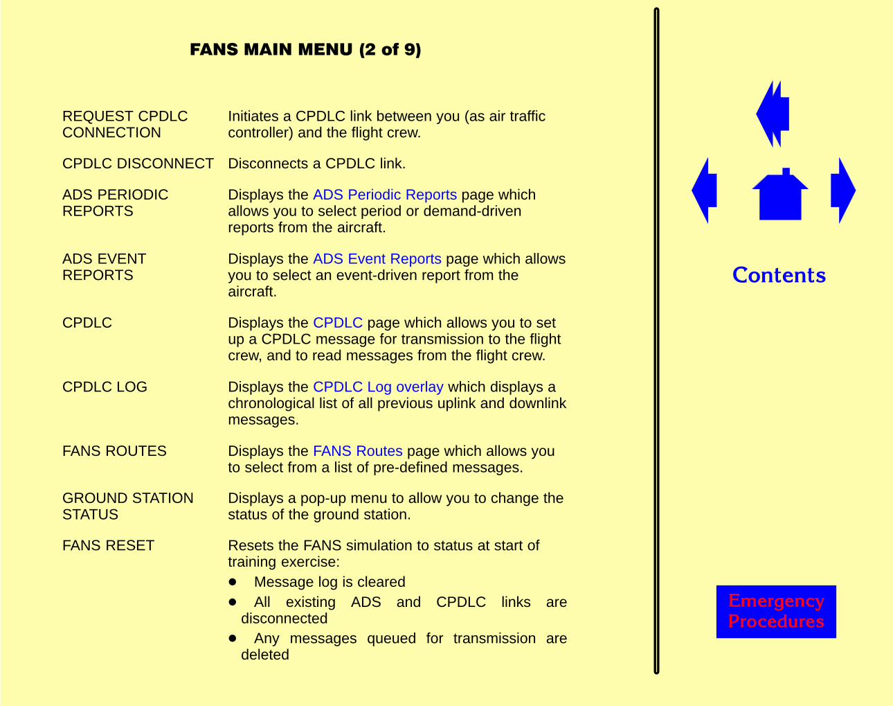
REQUEST CPDLCCONNECTION
Initiates a CPDLC link between you (as air trafficcontroller) and the flight crew.
CPDLC DISCONNECT Disconnects a CPDLC link.
ADS PERIODICREPORTS
Displays the ADS Periodic Reports page whichallows you to select period or demand-drivenreports from the aircraft.
ADS EVENTREPORTS
Displays the ADS Event Reports page which allowsyou to select an event-driven report from theaircraft.
CPDLC Displays the CPDLC page which allows you to setup a CPDLC message for transmission to the flightcrew, and to read messages from the flight crew.
CPDLC LOG Displays the CPDLC Log overlay which displays achronological list of all previous uplink and downlinkmessages.
FANS ROUTES Displays the FANS Routes page which allows youto select from a list of pre-defined messages.
GROUND STATIONSTATUS
Displays a pop-up menu to allow you to change thestatus of the ground station.
FANS RESET Resets the FANS simulation to status at start oftraining exercise:� Message log is cleared� All existing ADS and CPDLC links are
disconnected� Any messages queued for transmission are
deleted
��������
������� �������
����������������"���)
ADS PERIODIC REPORTS
This page is selectable from the FANS Main Menu page and allows you to selectperiod or demand-driven reports from the aircraft. The report is displayed on thepage.
PERIOD Allows you to set the time period betweenreports.
REQUEST PERIODICREPORT
Sends signal to the aircraft requestingreports to be sent at the specified timeperiod.
CANCEL PERIODIC REPORT Sends signal to the aircraft cancelling theperiodic report.
DEMAND REPORT Sends signal to the aircraft requesting animmediate report.
CLEAR DISPLAYS Clears the report window.
BASIC GROUPFLIGHT IDENT GROUPEARTH REF GROUPAIR REF GROUPMET GROUPPREDICTED ROUTE GROUPINT PROJ INTENT GROUPFIXED INTENT GROUP
Allow you to select which groups ofparameters are reported in a periodicreport.The buttons change colour to indicateselection status:Blue – not included in the reportGreen – included in the report, but notcurrently displayedAmber – included in the report andcurrently displayed in the report windowNOTE: The Basic Group are alwaysincluded in the report; the others areoptional.
��������
������� �������
����������������#���)
ADS EVENT REPORTS
This page is selectable from the FANS Main Menu page and allows you to selectan event-driven report from the aircraft.
VERTICAL RATELATERAL DEVIATIONALTITUDE CEILINGALTITUDE FLOORACTIVE WAYPOINTCHANGE
Allow you to set the event parameters that willinitiate the report.
REQUEST EVENTREPORT
Sends signal to the aircraft requesting report to besent when the specified event is reached.
CANCEL EVENTREPORT
Sends signal to the aircraft cancelling the eventreport.
��������
������� �������
��������������������)
CPDLC
This page is selectable from the FANS Main Menu page and allows you to set upa CPDLC message for transmission to the flight crew, and to read messages fromthe flight crew.
Downlink window Displays the message from the flight crew.
Uplink window Displays the message to be sent to the flight crew.Selecting CLEAR removes the message from thewindow.
Message buttons Allow you to select a message for editing andsubsequent transmission.The buttons initially display the groups ofmessages available. Selecting a group displaysthe messages associated with the group againstthe right-hand set of buttons. Selecting a messagedisplays the associated parameters against theright-hand set of buttons. Selecting a parameterdisplays the value of the parameter in the Uplinkwindow and you can use the keypad to edit thevalue.
SCROLL UPSCROLL DOWN
Allows you to scroll through the message buttondisplays.
KEYPAD Displays the alphanumeric keypad to allow you toedit/create messages.
SEND UPLINK Transmits the message in the Uplink window to theaircraft.

��������
������� �������
����������������'���)
FANS ROUTES
This page is selectable from the FANS Main Menu page and allows you to selectfrom a list of pre-defined messages. Up to 20 routes are available with up to 20messages per route. Select the required route and message, then select SENDUPLINK to send the message to the aircraft. Use the SCROLL UP/SCROLLDOWN buttons to scroll through the routes messages.
��������
������� �������
����������������&���)
CPDLC LOG OVERLAY
This overlay displays a chronological list of all previous uplink and downlinkmessages. Each entry provides an abbreviated version of the associatedmessage, the time received/sent and the status of the message. Selecting thebutton associated with a message displays the CPDLC Log Overlay 2 whichprovides the full text of the message.
SCROLL UPSCROLL DOWN
Allows you to scroll through the message buttondisplays.
��������
������� �������
����������������(���)
CPDLC LOG OVERLAY 2
This overlay displays the full text of an uplink or downlink message. If the statusof a downlink message is OPEN, then the SELECT RESPONSE button is enabled.Selecting this button displays the CPDLC page to allow you to prepare and senda response to the aircraft.
��������
������� �������
����������������)���)
DOWNLINK MESSAGE OVERLAY
This overlay is displayed automatically when a downlink is received from theaircraft. The downlink message is displayed, together with three possibleresponses. Select SEND to send the associated uplink response. If you do notwant to use one of the pre-selected messages, select OTHER which displays theCPDLC page to allow you to prepare and send an alternative response.

��������
������� �������
�����������������
This page is selectable from the Master Index page and displays current value oflisted aircraft and environment parameters.
����������������
������
���������
This page is selectable from the Master Index page and allows you to configure theFMC with route information.
LOAD TO FMC Programs the FMC with the information from theselected stored route.
HELP Programs the FMC with the information from theselected stored route.
PAGE UPPAGE DOWN
Allow you to scroll up/down through the list of availableflight plans.
MASTER INDEX Displays Master Index page.
HARD COPY Prints a copy of the current page on the hard copyprinter.
��������
������� �������
�������������
This page is selectable from the Master Index and allows you to suspend andrestart all or some of the simulated systems.
NOTE: IOS remains operational during all freeze states.
Freezes:
POSITIONFREEZE
Freezes aircraft at current geographical location. All otheraerodynamic and aircraft systems remain operational.
ALTITUDEFREEZE
Freezes aircraft altitude at current setting. All otheraerodynamic and aircraft systems remain operational.
FLIGHTFREEZE
Freezes aerodynamic parameters (aircraft speed, attitude,altitude and geographical position). Aircraft systems remainoperational.
FUELFREEZE
Freezes fuel quantities at current value. Engine fuel flowsunaffected, but no fuel depletion occurs.
TOTALFREEZE
Complete freeze of all simulated systems, except FMS.Simulator returns to level position and sound system isinhibited. Inputs to simulation from IOS and cockpit controlshave no effect.
Speedup:
SPEEDUP Allows aircraft ground speed to be changed (other aircraftparameters are not affected).
FUELJETTISON
��������
������� �������
�������������������������
This page is selectable from the Master Index page.
No. OfUsableSatellites
Allows you to change the number of usable satellites.
��������
������� �������
����������������������#
This page is selectable from the Normal Toolbar and allows you to select theappropriate lesson plan for the training exercise. Selection may be from either adedicated list or a pop–up list.
The lesson plan system enables a training session to be run automatically orsemi-automatically with minimum instructor intervention.
Each lesson plan consists of a series of events which are executed sequentially.The events can be activated automatically when a condition is satisfied (forexample, when a quantity reaches a specific level, or a pre-defined altitude isreached), or manually by selecting a button. In addition, it is possible to havenon–sequential events in the lesson plan which do not form part of the sequentialflow but can be selected at any time.
The lesson plans are created off-line using the Lesson Plan Editor utility..
The lesson plans can be displayed in either Profile view or List view.
NOTE: A lesson plan may be ‘locked’ in either view from the Editor.
When a lesson plan is selected, the associated lesson plan is displayed in eitherProfile view or List view, as defined in the Editor when the lesson plan is created.
Only one lesson plan can be active (running) at any time.
Profile View
The lesson plans are displayed graphically as a plot of altitude (vertical axis)against time (horizontal axis). Each lesson plan can be several hours in duration,but only a section of the plan can be displayed at any one time. Therefore, thedisplay scrolls automatically from left to right as the lesson proceeds, keeping thecurrent section of the lesson on the screen. Scroll arrows are provided to allow youto manually scroll through the lesson plan. A ‘time–bar’ is displayed along thehorizontal axis indicating the elapsed time since the lesson plan started.

��������
������� �������
�����������������������#
FULL LENGTH OF LESSON
PAGE BORDER
PAGE BORDER
Each lesson plan consists of a series of numbered events which are displayed asbuttons on the screen. As the lesson progresses, the events are activatedsequentially. Automatic events (indicated by an A) occur when the pre-setconditions are met; manual events (indicated by an M) require action by you beforethey become active. To execute a manual event, either touch the button and thenselect Execute from the pop–up menu, or select ENTER ITEM. To override thepreset conditions for an automatic event, either touch the button and then selectExecute from the pop–up menu, or select ENTER ITEM. In addition, you canoverride the event sequence to repeat or skip a particular section (for example).To jump to a particular event, select the appropriate button and then select Gotofrom the pop–up menu.
The status of each event in the lesson plan is indicated by the colour of theassociated button. The button is normally blue and changes to orange when theevent is active (ie., it is the current event), then to red when the event is executing.The button changes to dark green when the event is completed. If the lesson planis not running, all the buttons are grey and cannot be selected.
When selected, manual events may provide you with a number of different options,each of which may activate different actions. If an event is active, a popup appearsdisplaying the available options, an Execute button and a Close button. Thecurrently selected option will be activated when the Execute button is pressed. Ifan event is not active, a Goto button replaces the Execute button, but you can stillselect a ‘current’ option. This selection is retained when the task becomes activeand the ‘Execute’ popup is displayed. Options are mutually exclusive, ie., only oneoption can be selected during a given execution of a lesson plan.
If an event has multiple actions, the actions will be executed sequentially.
��������
������� �������
�������������������"���#
In the Lesson Plan Editor, it is possible to create complete sequencing scenariosby linking two events that would otherwise be disjointed. At run time, once the firstlinked event has been completed, the second linked event will become the currentevent; all intervening events are ignored.
List View
The lesson plans are displayed in a vertically sequenced list with the initial eventat the top of the screen. As the lesson progresses, the display scrolls vertically tokeep the current section of the lesson on the screen. Scroll arrow buttons areprovided to allow you to manually scroll through the lesson plan. Operation of thelesson plan is the same as in Profile view.
Operating a Lesson Plan
Buttons are provided along the bottom of the page to allow you to control the lesson:
� START and RESET & START (or STOP and RESET & STOP). Selecting eitherSTART or RESET & START starts the lesson plan. (RESET & START performsa Master Reset before starting the lesson plan). Selecting either STOP orRESET & STOP stops the lesson plan. (RESET & STOP performs a MasterReset before stopping the lesson plan).
� MODE, which allows you to switch between Manual and Automatic modes. InManual mode, automatic events must be manually selected before the eventwill start to monitor the preset conditions.
NOTE: A lesson plan can be ‘locked’ in either mode from the Lesson PlanEditor.
� MASTER INDEX, which displays the Master Index page to provide access tothe rest of the IOS pages.
� ENTER ITEM, which allows you to activate manual events. Automatic eventsalso respond to ENTER ITEM and act as if the associated preset conditionshave been satisfied.
� FORWARD and BACK arrow buttons, which allow you to scroll through thelesson plan.
��������
������� �������
�������������������#���#
� HARD COPY, which prints the page on the hard copy printer..
� VIEW, which switches between Profile and List view.
� ZOOM, which displays the whole lesson plan (in Profile view), or removesevent descriptions from display thus allowing more events to be displayed (inList view).
The lesson stops automatically when the last event has finished executing.

��������
������� �������
����
This page is displayed at system startup. Selecting START displays theMaster Index page.
��������
������� �������
�����������������
This page is selectable from the Master Index page and lists all the availableMaintenance pages which are provided for use by the technician to set up the IOSand to run acceptance tests on the simulator.
Use of the pages is password–protected.
��������
������� �������
�����������!��������������"
This page is selectable from the Normal Toolbar and displays the status ofmalfunctions, circuit breakers, radio stations and other entities.
Descriptive text lines appear, chronologically, at the display, with a time stamp ontheir incidence. When the number of incidents registered exceeds the pagecapacity, further pages are generated and linked.
Those conditions which may be reset are provided with selection buttons.
The information and control provided by this page are as follows:
� Active Malfunctions These are identified in red text. Selection of anassociated button displays a keypad, whichallows the malfunction definition to be displayed,or for it to be set inactive.
� Armed Malfunctions These are identified in yellow text, each with itsselected arming conditions. Selection of anassociated button displays a keypad, whichallows the malfunction definition to be displayed,for the arming conditions to be changed, for themalfunction to be activated, or for it to bedisarmed.
� Failed Stations Failed radio stations are identified in amber text.Selection of an associated button displays akeypad, with options to view the stationinformation, to restore the station (or to fail orrestore co-located facilities), or to select it as thearea map reference centre.
� “Soft” Circuit Breakers These are open (software), circuit breakerswhich are outside the simulated area and areidentified in white text. Selection of anassociated button closes the circuit breaker.
��������
������� �������
�����������!���������������"
� Circuit Breakers These are circuit breakers which are within thesimulated area and have been thermally tripped,and are identified in yellow text.
� Misc These are typically simulation “freeze” conditionsand are identified in green text. Selection of anassociated button resets the condition.
Along the lower section of the page are selection buttons which are provided to“de-clutter” the information display. These correspond to the above conditioncategories and their alternate action may be used to display or suppress the relatedinformation:
ACTIVE MALFS Controls the display of active malfunctions,coloured red when their display is enabled, bluewhen it is suppressed.
ARMED MALFS Controls the display of armed malfunctions,coloured yellow when their display is enabled,blue when it is suppressed.
FAILED STATIONS Controls the display of failed radio stations,coloured amber when their display is enabled,blue when it is suppressed.
PHYSICAL CB STATUS Controls the display of thermally tripped,physically present circuit breakers, colouredyellow when their display is enabled, blue when itis suppressed.
INSTRUCTOR CB TRIPS Controls the display of tripped software circuitbreakers, coloured white when their display isenabled, blue when it is suppressed.
��������
������� �������
�����������!�����������"���"
Misc Controls the display of other conditions, colouredgreen when their display is enabled, blue when itis suppressed.
NOTE: Popped circuit breakers must be manually reset.
��������
������� �������
����������������������'
This page is selectable from the Normal Toolbar and lists the available malfunctionpages by aircraft system to assist you in locating the required malfunction.
Selecting one of the aircraft system touchpoints displays the associatedmalfunction page which lists the available malfunctions for that system andincorporates a MALFUNCTION MODE selection touchpoint.
Two types of malfunction are available:
� Discrete (eg., Landing Gear Fail)
� Variable, where you can set the value for the malfunction (eg., Fuel Leak)
The selection procedure for discrete and variable malfunctions is similar, althoughthat for a variable malfunction allows for the associated parameter to be changed.
Malfunction Selection
The malfunctions can be set to take immediate effect, or can be armed to take effectwhen specified aircraft parameters reach a pre-determined value.
The MALFUNCTION MODE touchpoint allows you to select either DIRECT orARM.
In DIRECT mode, selecting a malfunction touchpoint immediately activates orde-activates the associated malfunction.
In ARM mode, selecting a malfunction displays a pop-up menu with selectionsaccording to malfunction status and type:
INFORMATION Displays a pop-up window which provides details of the causeand effect of the malfunction.
ARM Displays the Arm Malfunction pop-up menu which allows youto select the arming conditions for the malfunction. One ormore conditions can be specified, as required.When arming conditions have been set, the malfunctionbecomes active when the corresponding parameters reachthe selected values.

��������
������� �������
�����������������������'
ACTIVATE Only operable when the selected malfunction is inactive.Activates the malfunction immediately.
CLEAR Only operable when the selected malfunction is already armedor active. De-activates the malfunction immediately.
MODIFY Only displayed when a variable malfunction is selected.Displays the numeric keypad to allow you to change the valueof the malfunction parameter.
DEFAULT Only displayed when a variable malfunction is selected.Resets the malfunction parameter to the pre-defined defaultvalue (as indicated by the display adjacent to the malfunctionselection button).
Cancel Removes the menu from display.
��������
������� �������
�������������������"���'
ARM MALFUNCTION
This menu is displayed when a malfunction is selected in ARM mode and allowsyou to set one or more parameter conditions to trigger the selected malfunction.
( Used to identify the start of a trigger component in a triggerdefinition that includes more than one condition.
) Used to identify the end of a trigger component in a triggerdefinition that includes more than one condition.
CLR Only operable following data entry. Clears the last dataitem entered.
AC Only operable following data entry. Clears all thecomponents that have been entered.
OK Only operable when valid selection has been made. Usedto confirm your selections. Selected values will be enteredinto the simulation.
Cancel Removes the menu from the display.
TriggerParameters:
Flap Lever Displays the Flap Lever pop-up menu which allows you toselect one of a number of flap lever positions as the triggercondition.
Ldg GearLever
Displays the Ldg Gear Lever pop-up menu which allowsyou to select either UP or DOWN as the trigger condition.
Speed (IAS) Displays transition options (see below). Selecting anoption displays the numeric keypad to allow you to enter aspeed value as the trigger condition.

��������
������� �������
�������������������#���'
ARM MALFUNCTION (continued)
Speedcrosses V1Speedcrosses V2Speedcrosses Vref
Discrete selections
Altitude(AGL)
Displays transition options (see below). Selecting anoption displays the numeric keypad to allow you to enter analtitude (above ground level) value as the trigger condition.
Altitude(AMSL)
Displays transition options (see below). Selecting anoption displays the numeric keypad to allow you to enter analtitude (above mean sea level) value as the triggercondition.
Heading Displays transition options (see below). Selecting anoption displays the numeric keypad to allow you to enter aheading value as the trigger condition.
Timer Displays the Timer keypad to allow you to enter a time asthe trigger condition.
When a trigger component has been defined, and and or selections are displayedto allow further conditions to be added, if required.
��������
������� �������
�����������������������'
Transition Options
The transition options displayed depend on the type of parameter selected:
Angularparameters(heading)
<@ backs thru Sets the condition to activate when the aircraft turns leftthrough the specified angle.
@ crosses Sets the condition to activate when the parametercrosses the specified angle from a greater or lesserangle.
>@ veers thru Sets the condition to activate when the aircraft turns rightthrough the specified angle.
Non-angularparameters(speed, altitude)
<@ sinks below Sets the condition to activate when the parameterchanges to any value below the specified value from agreater value.
@ crosses Sets the condition to activate when the parametercrosses the specified value from a greater or lesservalue.
>@ rises above Sets the condition to activate when the parameterchanges to any value above the specified value from alesser value.
��������
������� �������
�������������������'���'
< less than Sets the condition to activate whenever the value is lessthan the specified value.
> greater than Sets the condition to activate whenever the value isgreater than the specified value.
��������
������� �������
����������
The Master Index provides access to the following pages:
ACARS TCAS
ATIS Unusual Attitudes
Circuit Breakers Configuration Not In Agreement
Comms Crash Conditions
ECL Simsoft Flight Conditions
Fans Motion Interlocks
Freeze/Speedup Customer Options
GPS Flight Plan
Radio Stations Maintenance Use Only
Slew Snapshot
AMTF USE ONLY This button enables the Maintenance Training mode andaccess to an extra suite of pages.
INSTRUCTORSREFERENCEMANUAL
Displays this document.
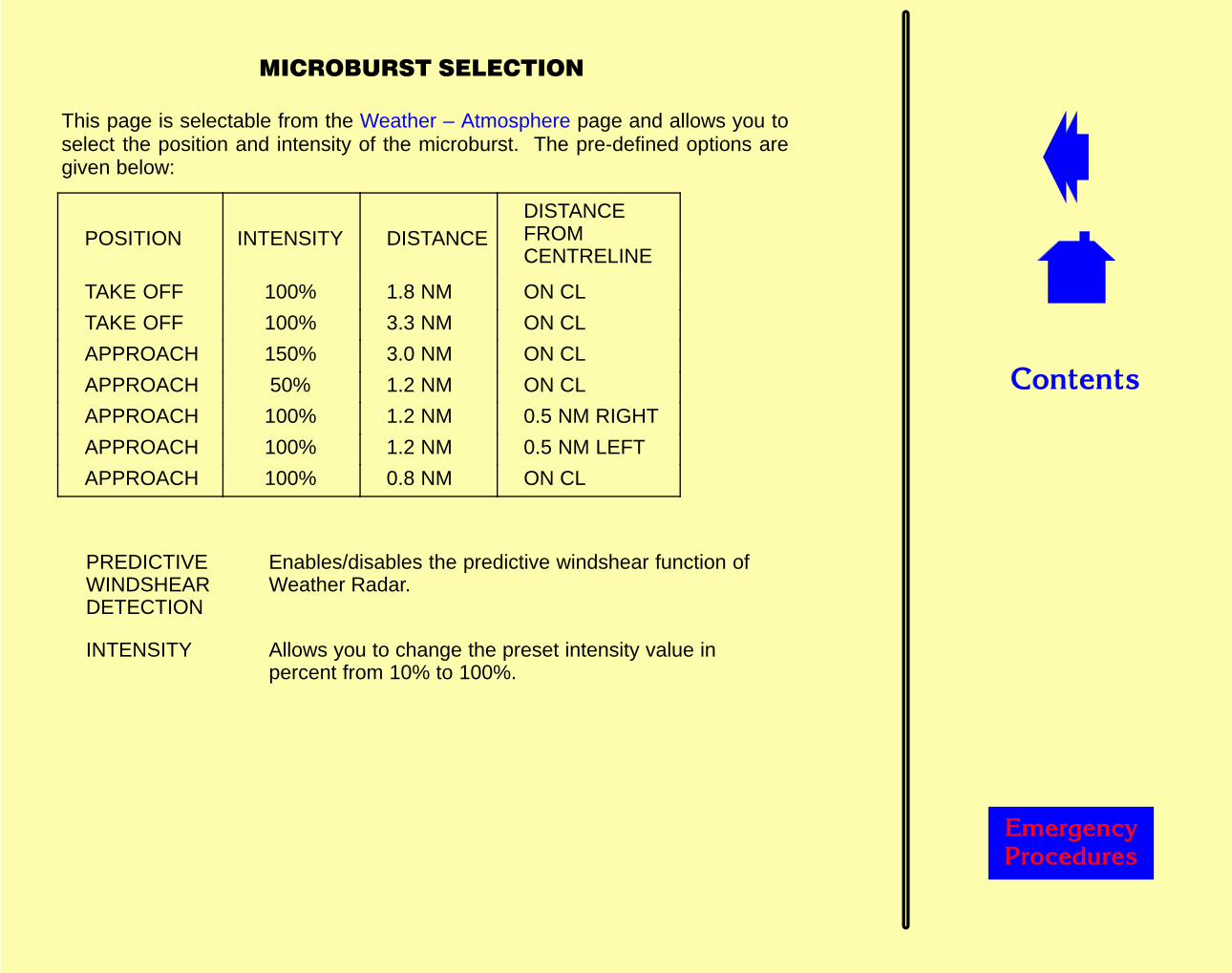
��������
������� �������
��������������������
This page is selectable from the Weather – Atmosphere page and allows you toselect the position and intensity of the microburst. The pre-defined options aregiven below:
POSITION INTENSITY DISTANCEDISTANCEFROMCENTRELINE
TAKE OFF 100% 1.8 NM ON CL
TAKE OFF 100% 3.3 NM ON CL
APPROACH 150% 3.0 NM ON CL
APPROACH 50% 1.2 NM ON CL
APPROACH 100% 1.2 NM 0.5 NM RIGHT
APPROACH 100% 1.2 NM 0.5 NM LEFT
APPROACH 100% 0.8 NM ON CL
PREDICTIVEWINDSHEARDETECTION
Enables/disables the predictive windshear function ofWeather Radar.
INTENSITY Allows you to change the preset intensity value inpercent from 10% to 100%.
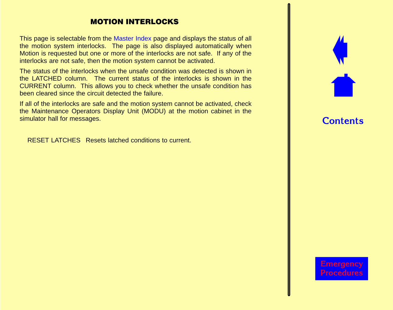
��������
������� �������
�����������������
This page is selectable from the Master Index page and displays the status of allthe motion system interlocks. The page is also displayed automatically whenMotion is requested but one or more of the interlocks are not safe. If any of theinterlocks are not safe, then the motion system cannot be activated.
The status of the interlocks when the unsafe condition was detected is shown inthe LATCHED column. The current status of the interlocks is shown in theCURRENT column. This allows you to check whether the unsafe condition hasbeen cleared since the circuit detected the failure.
If all of the interlocks are safe and the motion system cannot be activated, checkthe Maintenance Operators Display Unit (MODU) at the motion cabinet in thesimulator hall for messages.
RESET LATCHES Resets latched conditions to current.
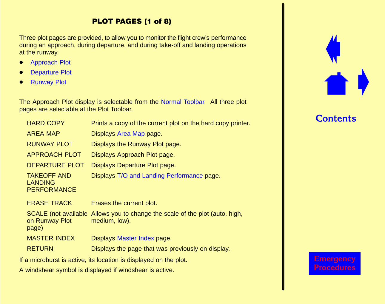
��������
������� �������
���������������(
Three plot pages are provided, to allow you to monitor the flight crew’s performanceduring an approach, during departure, and during take-off and landing operationsat the runway.
� Approach Plot
� Departure Plot
� Runway Plot
The Approach Plot display is selectable from the Normal Toolbar. All three plotpages are selectable at the Plot Toolbar.
HARD COPY Prints a copy of the current plot on the hard copy printer.
AREA MAP Displays Area Map page.
RUNWAY PLOT Displays the Runway Plot page.
APPROACH PLOT Displays Approach Plot page.
DEPARTURE PLOT Displays Departure Plot page.
TAKEOFF ANDLANDINGPERFORMANCE
Displays T/O and Landing Performance page.
ERASE TRACK Erases the current plot.
SCALE (not availableon Runway Plotpage)
Allows you to change the scale of the plot (auto, high,medium, low).
MASTER INDEX Displays Master Index page.
RETURN Displays the page that was previously on display.
If a microburst is active, its location is displayed on the plot.
A windshear symbol is displayed if windshear is active.
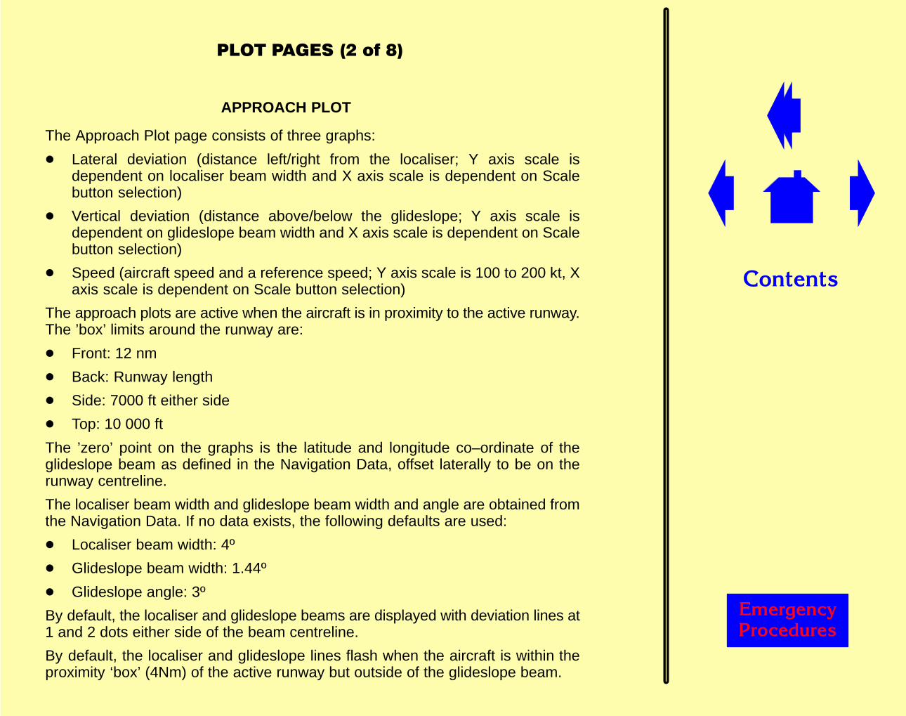
��������
������� �������
����������������(
APPROACH PLOT
The Approach Plot page consists of three graphs:
� Lateral deviation (distance left/right from the localiser; Y axis scale isdependent on localiser beam width and X axis scale is dependent on Scalebutton selection)
� Vertical deviation (distance above/below the glideslope; Y axis scale isdependent on glideslope beam width and X axis scale is dependent on Scalebutton selection)
� Speed (aircraft speed and a reference speed; Y axis scale is 100 to 200 kt, Xaxis scale is dependent on Scale button selection)
The approach plots are active when the aircraft is in proximity to the active runway.The ’box’ limits around the runway are:
� Front: 12 nm
� Back: Runway length
� Side: 7000 ft either side
� Top: 10 000 ft
The ’zero’ point on the graphs is the latitude and longitude co–ordinate of theglideslope beam as defined in the Navigation Data, offset laterally to be on therunway centreline.
The localiser beam width and glideslope beam width and angle are obtained fromthe Navigation Data. If no data exists, the following defaults are used:
� Localiser beam width: 4º
� Glideslope beam width: 1.44º
� Glideslope angle: 3º
By default, the localiser and glideslope beams are displayed with deviation lines at1 and 2 dots either side of the beam centreline.
By default, the localiser and glideslope lines flash when the aircraft is within theproximity ‘box’ (4Nm) of the active runway but outside of the glideslope beam.
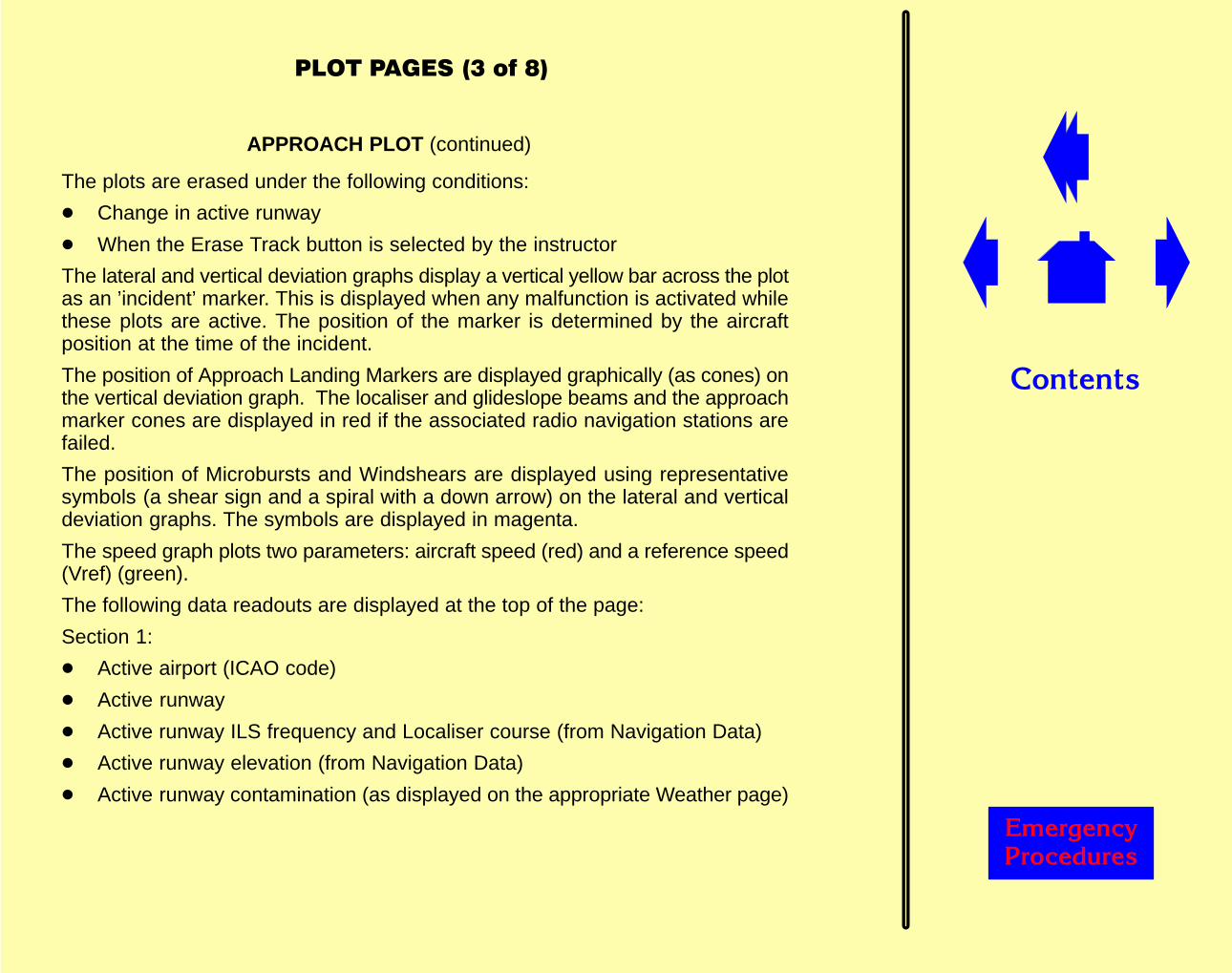
��������
������� �������
������������"���(
APPROACH PLOT (continued)
The plots are erased under the following conditions:
� Change in active runway
� When the Erase Track button is selected by the instructor
The lateral and vertical deviation graphs display a vertical yellow bar across the plotas an ’incident’ marker. This is displayed when any malfunction is activated whilethese plots are active. The position of the marker is determined by the aircraftposition at the time of the incident.
The position of Approach Landing Markers are displayed graphically (as cones) onthe vertical deviation graph. The localiser and glideslope beams and the approachmarker cones are displayed in red if the associated radio navigation stations arefailed.
The position of Microbursts and Windshears are displayed using representativesymbols (a shear sign and a spiral with a down arrow) on the lateral and verticaldeviation graphs. The symbols are displayed in magenta.
The speed graph plots two parameters: aircraft speed (red) and a reference speed(Vref) (green).
The following data readouts are displayed at the top of the page:
Section 1:
� Active airport (ICAO code)
� Active runway
� Active runway ILS frequency and Localiser course (from Navigation Data)
� Active runway elevation (from Navigation Data)
� Active runway contamination (as displayed on the appropriate Weather page)

��������
������� �������
������������#���(
APPROACH PLOT (continued)
Section 2:
� Gust (as displayed on the Weather – Cloud and Wind page)
� Surface wind speed and direction (as displayed in the standard readouts area)
� Field temperature (as displayed in the standard readouts area)
� Gross Weight (as displayed in the standard readouts area)
Section 3:
� Current glideslope deviation.
This is the current deviation distance in dots from the active runway glideslopebeam centreline (or virtual glide–slope if non–GS equipped). It is alwayscalculated, irrespective of aircraft position.
� Current localiser deviation.
This is the current deviation distance in dots from the active runway centre line.It is always calculated, irrespective of the aircraft’s position.
� Maximum glideslope deviation
This is the maximum glideslope deviation from the active runway. It is alwayscalculated, irrespective of the aircraft’s position.
� Maximum localiser deviation
This is the maximum localiser deviation from the active runway. It is alwayscalculated, irrespective of the aircraft’s position.
� Threshold crossing height
This is the height at which the aircraft crosses the runway threshold as it fliesdown the ILS glideslope.
� Touchdown distance
This is the point to point distance from the aircraft to the active runwaytouchdown zone. This touchdown zone is represented on most runways as 2large white blocks either side of the runway centreline, approximately 1000ftfrom the runway threshold.
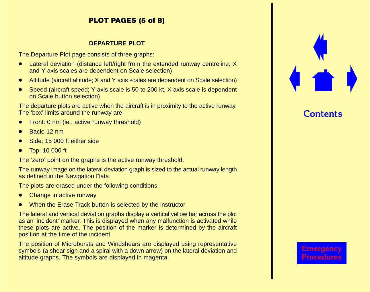
��������
������� �������
����������������(
DEPARTURE PLOT
The Departure Plot page consists of three graphs:
� Lateral deviation (distance left/right from the extended runway centreline; Xand Y axis scales are dependent on Scale selection)
� Altitude (aircraft altitude; X and Y axis scales are dependent on Scale selection)
� Speed (aircraft speed; Y axis scale is 50 to 200 kt, X axis scale is dependenton Scale button selection)
The departure plots are active when the aircraft is in proximity to the active runway.The ’box’ limits around the runway are:
� Front: 0 nm (ie., active runway threshold)
� Back: 12 nm
� Side: 15 000 ft either side
� Top: 10 000 ft
The ’zero’ point on the graphs is the active runway threshold.
The runway image on the lateral deviation graph is sized to the actual runway lengthas defined in the Navigation Data.
The plots are erased under the following conditions:
� Change in active runway
� When the Erase Track button is selected by the instructor
The lateral and vertical deviation graphs display a vertical yellow bar across the plotas an ’incident’ marker. This is displayed when any malfunction is activated whilethese plots are active. The position of the marker is determined by the aircraftposition at the time of the incident.
The position of Microbursts and Windshears are displayed using representativesymbols (a shear sign and a spiral with a down arrow) on the lateral deviation andaltitude graphs. The symbols are displayed in magenta.
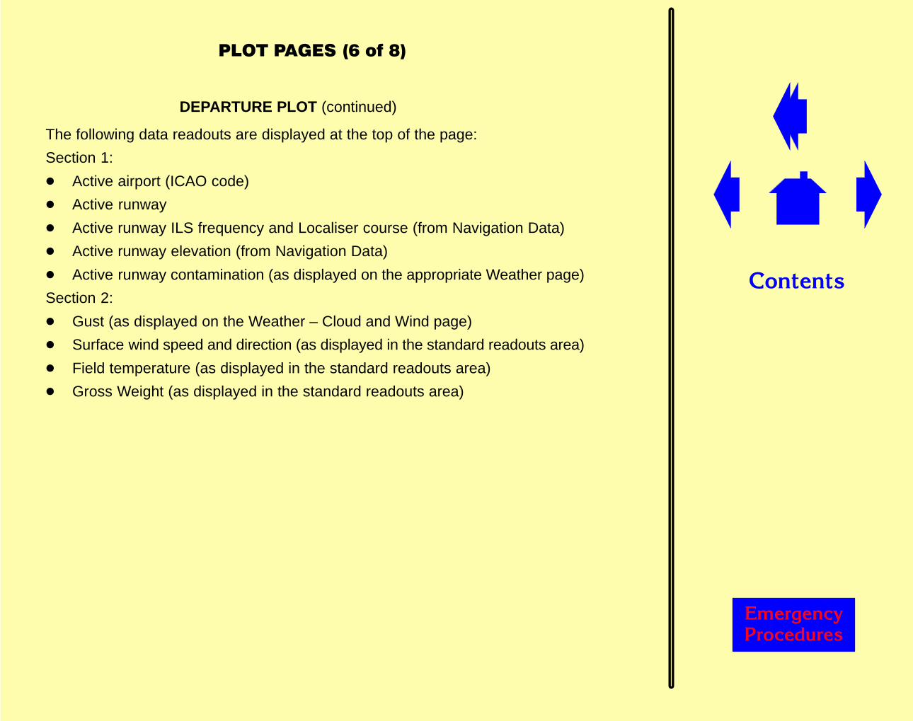
��������
������� �������
������������'���(
DEPARTURE PLOT (continued)
The following data readouts are displayed at the top of the page:
Section 1:
� Active airport (ICAO code)
� Active runway
� Active runway ILS frequency and Localiser course (from Navigation Data)
� Active runway elevation (from Navigation Data)
� Active runway contamination (as displayed on the appropriate Weather page)
Section 2:
� Gust (as displayed on the Weather – Cloud and Wind page)
� Surface wind speed and direction (as displayed in the standard readouts area)
� Field temperature (as displayed in the standard readouts area)
� Gross Weight (as displayed in the standard readouts area)

��������
������� �������
������������&���(
RUNWAY PLOT
The Runway Plot page consists of four graphs:
� Aircraft position (aircraft position on the runway; Y axis scale is dependent onrunway width, X axis scale is dependent on runway length)
� Brake pedals (left and right pedal deflection; Y axis scale is 0 to100 %, X axisscale is dependent on runway length
� Speed (aircraft speed; Y axis scale is 0 to 200 kt, X axis scale is dependent onrunway length)
� Rudder pedal (deflection left (negative) and right (positive) in degrees; Y axisscale is –20º to +20º, X axis scale is dependent on runway length)
The runway plots are active when the aircraft is on the active runway or less than35 ft above it.
The ’zero’ point on the graphs is the active runway threshold.
The graphs are sized to the actual active runway length as defined in the NavigationData. There is no Scale control.
The plots are erased under the following conditions:
� Change in active runway
� When the Erase Track button is selected by the instructor
The position of Microbursts and Windshears are displayed using representativesymbols (a shear sign and a spiral with a down arrow) on the aircraft position graph.The symbols are displayed in magenta.
The aircraft position graph displays a vertical yellow bar as an ’incident’ marker.This is displayed when any malfunction is activated while this plot is active.
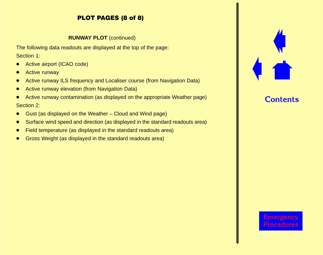
��������
������� �������
������������(���(
RUNWAY PLOT (continued)
The following data readouts are displayed at the top of the page:
Section 1:
� Active airport (ICAO code)
� Active runway
� Active runway ILS frequency and Localiser course (from Navigation Data)
� Active runway elevation (from Navigation Data)
� Active runway contamination (as displayed on the appropriate Weather page)
Section 2:
� Gust (as displayed on the Weather – Cloud and Wind page)
� Surface wind speed and direction (as displayed in the standard readouts area)
� Field temperature (as displayed in the standard readouts area)
� Gross Weight (as displayed in the standard readouts area)
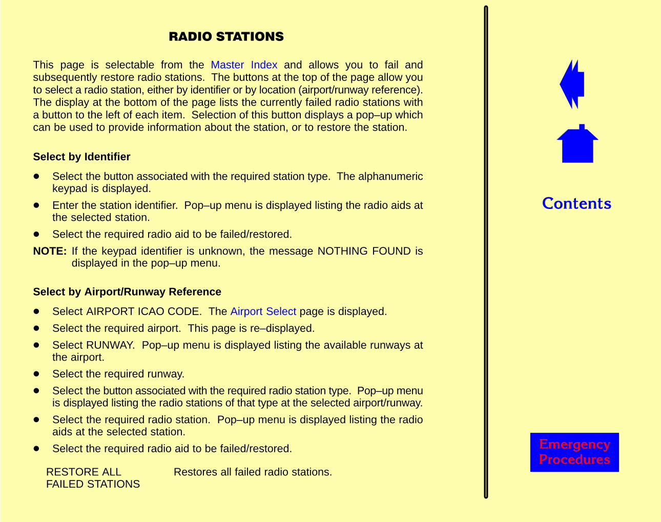
��������
������� �������
��������������
This page is selectable from the Master Index and allows you to fail andsubsequently restore radio stations. The buttons at the top of the page allow youto select a radio station, either by identifier or by location (airport/runway reference).The display at the bottom of the page lists the currently failed radio stations witha button to the left of each item. Selection of this button displays a pop–up whichcan be used to provide information about the station, or to restore the station.
Select by Identifier
� Select the button associated with the required station type. The alphanumerickeypad is displayed.
� Enter the station identifier. Pop–up menu is displayed listing the radio aids atthe selected station.
� Select the required radio aid to be failed/restored.
NOTE: If the keypad identifier is unknown, the message NOTHING FOUND isdisplayed in the pop–up menu.
Select by Airport/Runway Reference
� Select AIRPORT ICAO CODE. The Airport Select page is displayed.
� Select the required airport. This page is re–displayed.
� Select RUNWAY. Pop–up menu is displayed listing the available runways atthe airport.
� Select the required runway.
� Select the button associated with the required radio station type. Pop–up menuis displayed listing the radio stations of that type at the selected airport/runway.
� Select the required radio station. Pop–up menu is displayed listing the radioaids at the selected station.
� Select the required radio aid to be failed/restored.
RESTORE ALLFAILED STATIONS
Restores all failed radio stations.
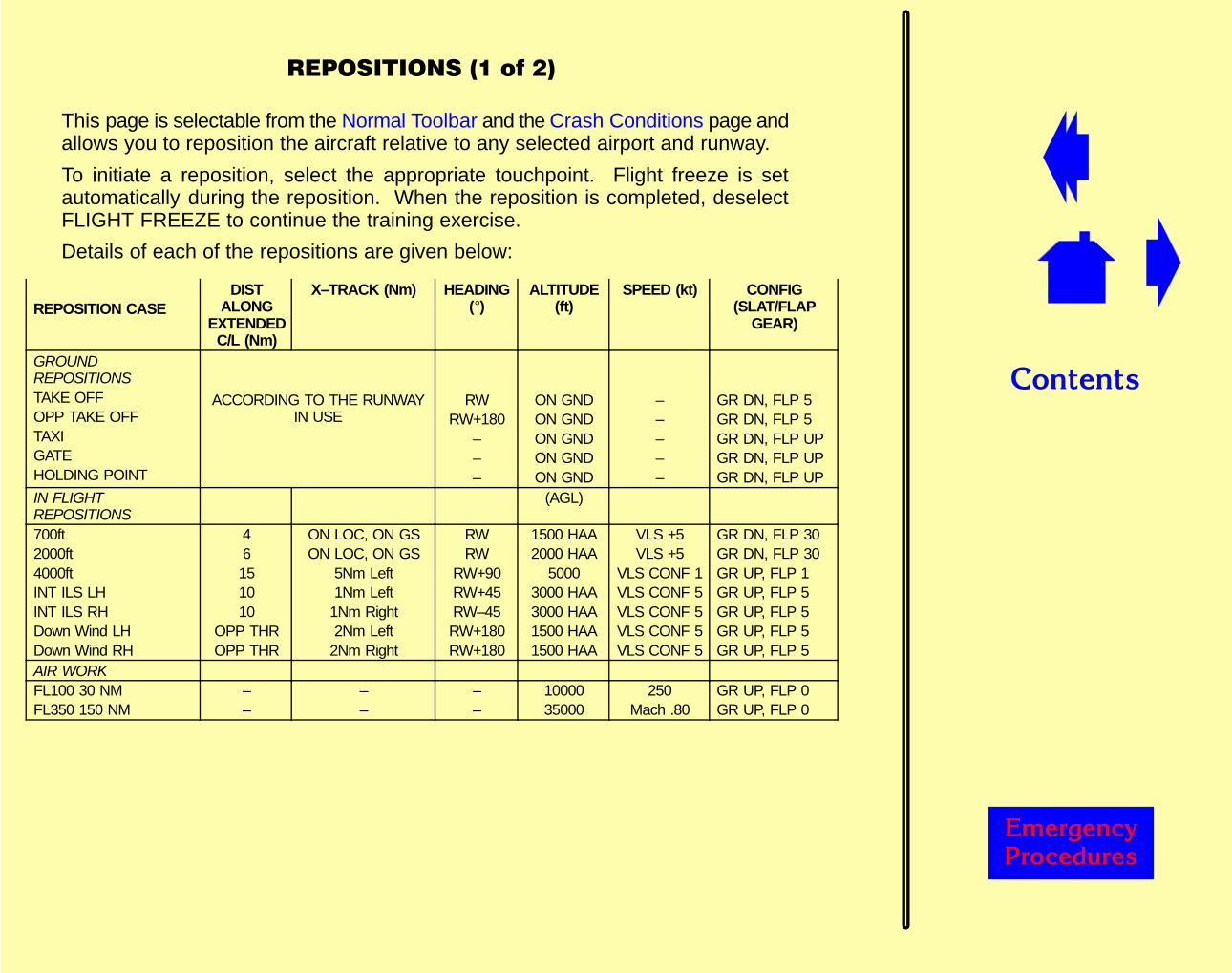
��������
������� �������
�����������������
This page is selectable from the Normal Toolbar and the Crash Conditions page andallows you to reposition the aircraft relative to any selected airport and runway.
To initiate a reposition, select the appropriate touchpoint. Flight freeze is setautomatically during the reposition. When the reposition is completed, deselectFLIGHT FREEZE to continue the training exercise.
Details of each of the repositions are given below:
REPOSITION CASEDIST
ALONGEXTENDED
C/L (Nm)
X–TRACK (Nm) HEADING(�)
ALTITUDE(ft)
SPEED (kt) CONFIG(SLAT/FLAP
GEAR)
GROUNDREPOSITIONSTAKE OFFOPP TAKE OFFTAXIGATEHOLDING POINT
ACCORDING TO THE RUNWAYIN USE
RWRW+180
–––
ON GNDON GNDON GNDON GNDON GND
–––––
GR DN, FLP 5GR DN, FLP 5GR DN, FLP UPGR DN, FLP UPGR DN, FLP UP
IN FLIGHTREPOSITIONS
(AGL)
700ft2000ft4000ftINT ILS LHINT ILS RHDown Wind LHDown Wind RH
46151010
OPP THROPP THR
ON LOC, ON GSON LOC, ON GS
5Nm Left1Nm Left
1Nm Right2Nm Left
2Nm Right
RWRW
RW+90RW+45RW–45RW+180RW+180
1500 HAA2000 HAA
50003000 HAA3000 HAA1500 HAA1500 HAA
VLS +5VLS +5
VLS CONF 1VLS CONF 5VLS CONF 5VLS CONF 5VLS CONF 5
GR DN, FLP 30GR DN, FLP 30GR UP, FLP 1GR UP, FLP 5GR UP, FLP 5GR UP, FLP 5GR UP, FLP 5
AIR WORKFL100 30 NMFL350 150 NM
––
––
––
1000035000
250Mach .80
GR UP, FLP 0GR UP, FLP 0
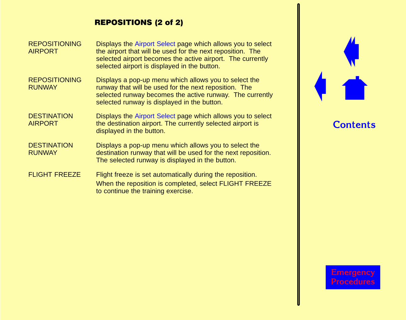
��������
������� �������
������������� ��
REPOSITIONINGAIRPORT
Displays the Airport Select page which allows you to selectthe airport that will be used for the next reposition. Theselected airport becomes the active airport. The currentlyselected airport is displayed in the button.
REPOSITIONINGRUNWAY
Displays a pop-up menu which allows you to select therunway that will be used for the next reposition. Theselected runway becomes the active runway. The currentlyselected runway is displayed in the button.
DESTINATIONAIRPORT
Displays the Airport Select page which allows you to selectthe destination airport. The currently selected airport isdisplayed in the button.
DESTINATIONRUNWAY
Displays a pop-up menu which allows you to select thedestination runway that will be used for the next reposition.The selected runway is displayed in the button.
FLIGHT FREEZE Flight freeze is set automatically during the reposition.When the reposition is completed, select FLIGHT FREEZEto continue the training exercise.
��������
������� �������
�������������
This page is selectable from the Normal Toolbar and allows you to reset the aircraftsystems to normal operating conditions
Main Resets:
MASTER RESET Resets all systems and temperatures defined on thesecond page to normal operating conditions. Resets allactive and armed malfunctions, restores all failednavigational facilities and clears all circuit breaker tripconditions.NOTE: Popped circuit breakers must be manually reset.
SYSTEM RESET Resets all systems defined on the page to normaloperating conditions.
CLEAR ALLMALFUNCTIONS
Resets all active and armed malfunctions, restores allfailed radio stations and clears all circuit breaker tripconditions.
ENVIRONMENTRESET
Selects standard day weather conditions:Tropopause level: FL360QNH: 1013.25 mbTemperature gradient: –1.98°C/1000 ftSea level temperature: 15°CDelta ISA: 0°C
RADIO STATIONS Displays Radio Stations page.
FMC AUTOLOADDISABLE
Selection disables the FMC to autoload a designated flightplan when the aircraft is repositioned for takeoff.
��������
������� �������
�������������
System Resets:
APU Refills APU oil tank to normal level.
BATTERY Resets batteries to fully charged.
CABINPRESSURE
Resets cabin pressure to appropriate value for currentconditions.
ENGINE Resets engine RPM to normal operating level.
ENGINE OIL QTY Refills all engine oil tanks to normal levels.
FIREEXTINGUISHER
Refills all fire bottles to normal levels.
HYDRAULIC QTY Refills all hydraulic reservoirs to normal levels.
IDG RECONNECT Reconnects engine–driven generator.
OXYGEN Replenishes oxygen cylinders to normal levels and resetspassenger oxygen system (if deployed).
RAM AIRTURBINE
Resets the Ram Air Turbine.
TYRE PRESSURE Resets all deflated tyres to normal operating pressure.
��������
������� �������
������������
Temperature Resets:
BRAKE Resets all brake pad temperatures to ambient level.
EGT Resets exhaust gas temperature to normal operatingvalue.
ENGINE OIL Refills all engine oil tanks to normal levels.
FLT DECK/CABIN Resets air conditioning temperature to normal operatinglevel.
FUEL Resets fuel temperature to normal operating value.
HYDRAULICFLUID
Refills all hydraulic reservoirs to normal levels.
IDG OIL Resets IDG oil temperature to normal operating value.
WINDOW Resets window heater temperature to normal operatinglevel.
��������
������� �������
��������������
This page is selectable from the Weather – Visual/Rwy Conds page and allows youto control the appearance and movement of up to sixteen incidences of routedtraffic. These incidents are normally designed to present the aircrew with a hazard,in the vicinity of the runway, during take-off or landing. They may, additionally, beused to provide traffic scenarios in and around the airport.
STANDBY Establishes the traffic object at the start of its recorded route. Ifthe associated traffic object is already established, this selectionterminates it and removes it from display.
START/STOP When traffic is inactive at standby, initiates movement of the trafficobject along its route. When the traffic is active, stops itsmovement, subsequent selection causes the movement toresume.
A summary of the routed traffic model is aligned with each pair of control buttons,to define the vehicle concerned and its scheduled performance.
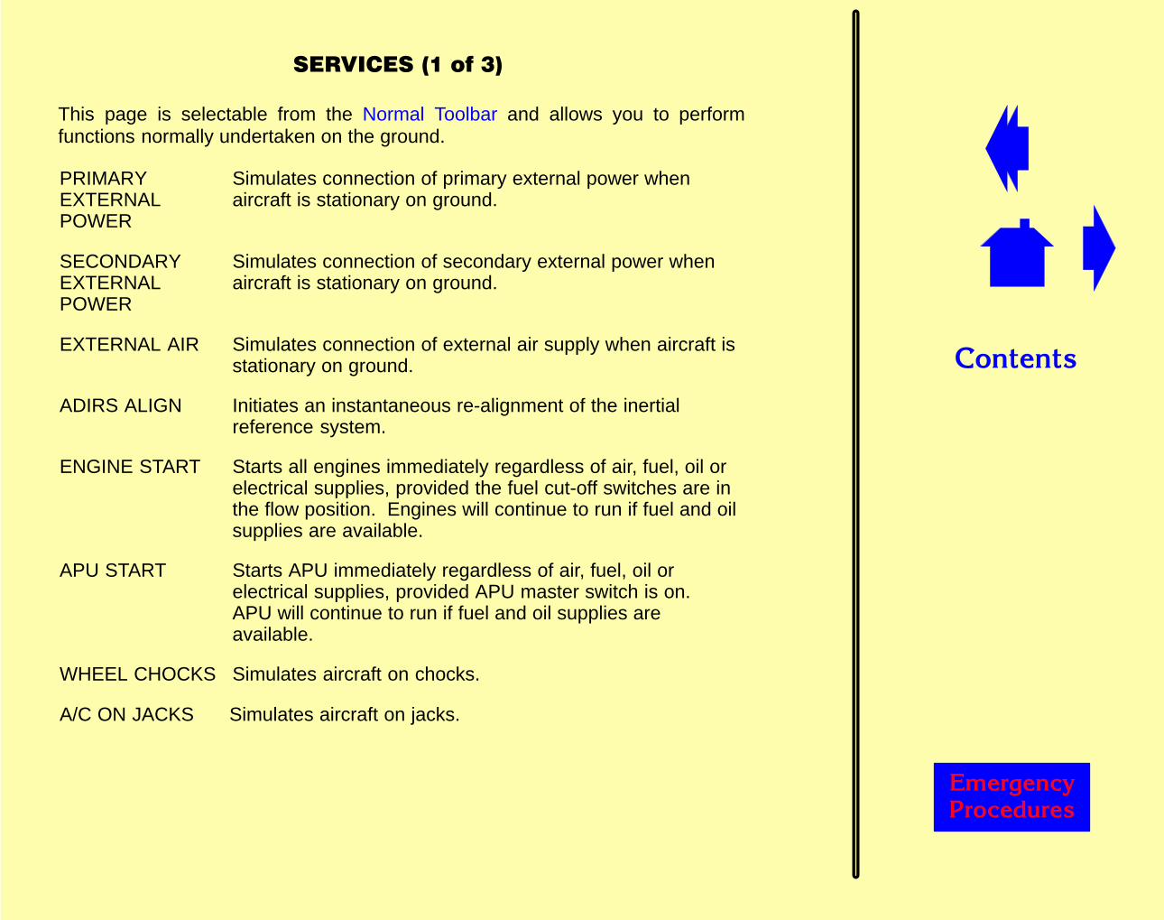
��������
������� �������
�������������"
This page is selectable from the Normal Toolbar and allows you to performfunctions normally undertaken on the ground.
PRIMARYEXTERNALPOWER
Simulates connection of primary external power whenaircraft is stationary on ground.
SECONDARYEXTERNALPOWER
Simulates connection of secondary external power whenaircraft is stationary on ground.
EXTERNAL AIR Simulates connection of external air supply when aircraft isstationary on ground.
ADIRS ALIGN Initiates an instantaneous re-alignment of the inertialreference system.
ENGINE START Starts all engines immediately regardless of air, fuel, oil orelectrical supplies, provided the fuel cut-off switches are inthe flow position. Engines will continue to run if fuel and oilsupplies are available.
APU START Starts APU immediately regardless of air, fuel, oil orelectrical supplies, provided APU master switch is on.APU will continue to run if fuel and oil supplies areavailable.
WHEEL CHOCKS Simulates aircraft on chocks.
A/C ON JACKS Simulates aircraft on jacks.
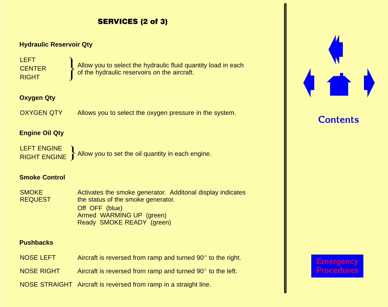
��������
������� �������
��������������"
Hydraulic Reservoir Qty
LEFTCENTERRIGHT
Allow you to select the hydraulic fluid quantity load in eachof the hydraulic reservoirs on the aircraft.
Oxygen Qty
OXYGEN QTY Allows you to select the oxygen pressure in the system.
Engine Oil Qty
LEFT ENGINERIGHT ENGINE Allow you to set the oil quantity in each engine.
Smoke Control
SMOKEREQUEST
Activates the smoke generator. Additonal display indicatesthe status of the smoke generator.Off OFF (blue)Armed WARMING UP (green)Ready SMOKE READY (green)
Pushbacks
NOSE LEFT Aircraft is reversed from ramp and turned 90� to the right.
NOSE RIGHT Aircraft is reversed from ramp and turned 90� to the left.
NOSE STRAIGHT Aircraft is reversed from ramp in a straight line.
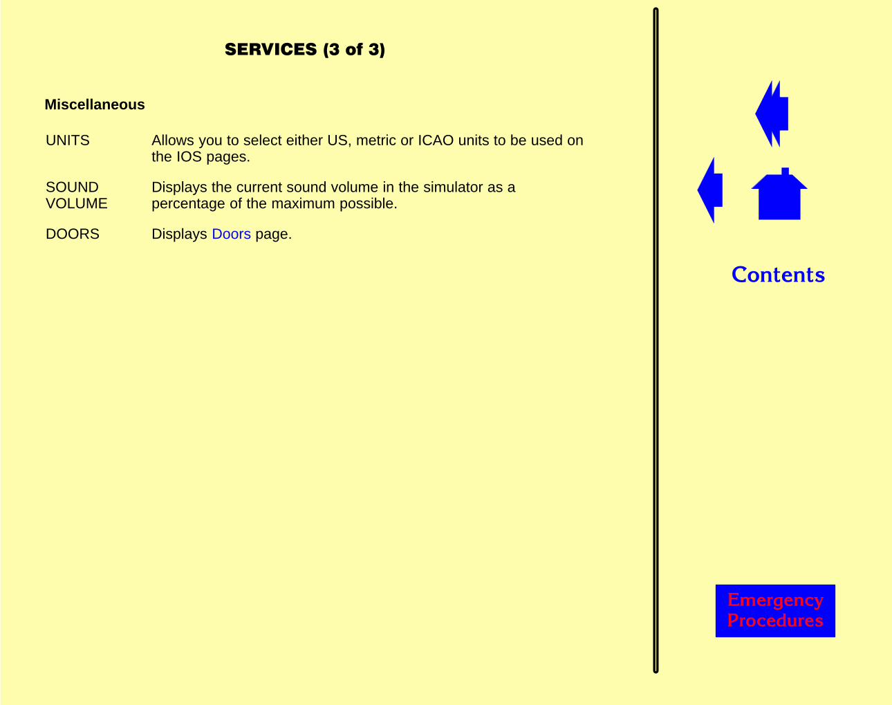
��������
������� �������
���������������
Miscellaneous
UNITS Allows you to select either US, metric or ICAO units to be used onthe IOS pages.
SOUNDVOLUME
Displays the current sound volume in the simulator as apercentage of the maximum possible.
DOORS Displays Doors page.

��������
������� �������
����
This page is selectable from the Master Index page.
NOTE: Flight Freeze is set automatically during reposition.
Aircraft Allows aircraft to be repositioned relative to its currentposition. Selecting a touchpoint moves the aircraft in thatdirection. Aircraft stops moving when finger is removed fromtouchpoint.
Geographic Allows aircraft to be repositioned relative to its geographicheading. Selecting a touchpoint moves the aircraft in thatdirection. Aircraft stops moving when finger is removed fromtouchpoint.
HEADINGALTITUDESPEEDMACH No
Allow value of associated parameters to be changed.
SPEED UP Displays a pop–up menu which allows you to increase theaircraft ground speed by a factor of 1, 2 or 4 (other aircraftparameters are not affected).
LATITUDE Allows you to change the latitude of the aircraft using anumeric keypad.
LONGITUDE Allows you to change the longitude of the aircraft using anumeric keypad.
ACTIVATE Activates the selected latitude/longitude settings.
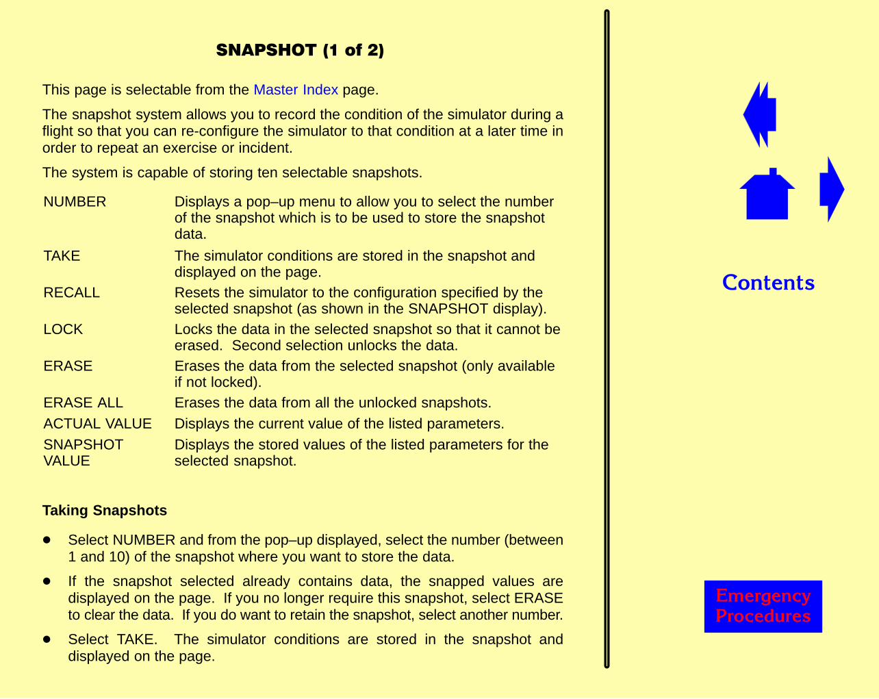
����������������
������
������������� �
This page is selectable from the Master Index page.
The snapshot system allows you to record the condition of the simulator during aflight so that you can re-configure the simulator to that condition at a later time inorder to repeat an exercise or incident.
The system is capable of storing ten selectable snapshots.
NUMBER Displays a pop–up menu to allow you to select the numberof the snapshot which is to be used to store the snapshotdata.
TAKE The simulator conditions are stored in the snapshot anddisplayed on the page.
RECALL Resets the simulator to the configuration specified by theselected snapshot (as shown in the SNAPSHOT display).
LOCK Locks the data in the selected snapshot so that it cannot beerased. Second selection unlocks the data.
ERASE Erases the data from the selected snapshot (only availableif not locked).
ERASE ALL Erases the data from all the unlocked snapshots.ACTUAL VALUE Displays the current value of the listed parameters.SNAPSHOTVALUE
Displays the stored values of the listed parameters for theselected snapshot.
Taking Snapshots
� Select NUMBER and from the pop–up displayed, select the number (between1 and 10) of the snapshot where you want to store the data.
� If the snapshot selected already contains data, the snapped values aredisplayed on the page. If you no longer require this snapshot, select ERASEto clear the data. If you do want to retain the snapshot, select another number.
� Select TAKE. The simulator conditions are stored in the snapshot anddisplayed on the page.
����������������
������
��������� ���� �
NOTE: Armed malfunctions are not recorded as part of the snapshot as they arenot active and do not form part of the current state of the simulator.
Recalling Snapshots
� Select NUMBER and and from the pop–up displayed select the number of thesnapshot you want to recall. The data in the snapshot is displayed on the page.
� Select RECALL to re-configure the simulator to the conditions in the snapshot.Flight Freeze is set automatically during the reposition.
� Deselect FLIGHT FREEZE on the Freezes page to re-run the exercise from thepoint of the snapshot.
NOTE: Armed malfunctions will be cleared and any active lesson plan will bestopped following a snapshot recall.
Clearing Snapshots
� Select ERASE ALL to remove all unlocked snapshot data.
� Select ERASE to remove the data from the selected snapshot (if unlocked).
Locking Snapshots
� Select LOCK to prevent the selected snapshot from being erased.
� Re-select LOCK to unlock the snapshot so that the data can be erased and anew snapshot taken.

��������
������� �������
�!�������������������������
This page is selectable from the Plot pages and displays the values of variousaircraft parameters during take–off and landing to enable you to check theperformance of the flight crew.
��������
������� �������
�����������
PREDICTABLE SCENARIOS
This page allows selection of scenarios that will generate a predictable TCAS voicecall–out. The requested voice call–out will be generated as long as the ownaircraft’s manoeuvres are within the limits specified for the selected scenario.
The Vertical Separation / Distance diagram displays the initial range and verticalseparation. It also shows the intruder relative altitude that will be maintained duringthe progress of the scenario.
The Intruder Bearing / Heading Diagram displays the initial relative bearing/headingof the intruder; range is not representative in this diagram.
SCENARIO SELECT Arms the associated scenario and the diagrams willreflect the initial positions of the own aircraft andintruder.
SCROLL UP/SCROLLDOWN
Scrolls through the list of available scenarios.
RUN SCENARIO Activates the armed scenario if the own aircraft iswithin the specified limits displayed for the selectedscenario.
STOP SCENARIO Stops the active scenario.
OWN AIRCRAFTPERFORMANCEREQUIREMENTS
Lists the altitude, vertical speed and ground speedlimits that have to be maintained by the own aircraftin order to obtain the requested voice call–out. Thisdisplay will flash to an exceeded limits displaywhen the own aircraft is outside these limits.
��������
������� �������
�����������
RANDOM TRAFFIC
This page allows you to select conflicting traffic in the terminal area, or to select arandom single aircraft approaching from a defined direction.
Random traffic is selected from the following aircraft types: ATR42, B747–400,B737–300, B757–200, B767–300, A320, A340.
AIR TRAFFIC CONTROL
LIGHT TRAFFICMEDIUM TRAFFICHEAVY TRAFFIC
Activates terminal area traffic flying a fixedroute relative to the active runway. Aircraftseparation on the route is dependent on thetraffic density selected.
RANDOM TRAFFIC
AHEADBEHINDLEFTRIGHTABOVEBELOWLEVEL
Arms a scenario with a single aircraftapproaching from the selected directions.
START Activates the selected random traffic scenario.
STOP Deactivates random traffic.
��������
������� �������
������ ����
PRESET SCENARIOS
These pages are selectable from the Master Index and allow you to set up TCASscenarios. Each scenario can consist of up to two intruder aircraft (aircraft posinga threat to your aircraft) and up to four proximate traffic aircraft (incidental trafficwithin the environment of your aircraft).
Intruder or proximate traffic aircraft are selected randomly from the following aircrafttypes: ATR42, B747–400, B737–300, B757–200, B767–300, A320, A340.
NOTE: If you select an intruder aircraft with no transponder fitted, the system willdisplay an ATR42 only.
ARM SCENARIO1 to 8
Arm the associated scenario and traffic is shown on theTCAS display. A summary of the scenario is displayedwithin each touchpoint.
SCENARIOSTATUS
Readouts which provide a summary of the data relatingto the intruders in the current active scenario.
RUN SCENARIO Activates the armed scenario. The TCAS display showsthe movement of the traffic.
STOP SCENARIO Stops the active scenario.
PROXIMATETRAFFIC
Allows proximate aircraft to be selected on or off withinthe selected scenario.
����������������
������
�����������
EDITABLE SCENARIOS
The page allows you to change the flight plan for each of the two intruder aircraftin the armed scenario. The touchpoints allow you to set the initial and final bearing,distance and altitude of the intruders relative to your aircraft. The speed of theintruders can also be set.
Intruder or proximate traffic aircraft are selected randomly from the following aircrafttypes: ATR42, B747–400, B737–300, B757–200, B767–300, A320, A340.
NOTE: If you select an intruder aircraft with no transponder fitted, the system willdisplay an ATR42 only.
TRANSPONDERTYPE
Displays a pop-up menu to allow you to select the TCAStransponder equipment fitted to the intruder.
CLEARINTRUDER
Clears all the existing parameters for the associatedintruder.
RUN SCENARIO Activates the armed scenario. The TCAS display showsthe movement of the traffic.
STOP SCENARIO Stops the active scenario.
����������������
������
������������������� ����
Scenarios
This page is selectable from the Master Index page and provides you with eightscenarios for Unusual Attitude Recovery Training. These scenarios are achievedby dynamically upsetting the simulator to attain a target pitch and/or bank angle.During this time, Pilot Pitch Controls will have not effect if a Target Pitch is selected,and Pilot Roll and Yaw controls will have no effect if a Target Bank is selected, Thescenarios are not available when the aircraft is on the ground or during a repositionwith the motion system engaged.
The scenarios are summarised as:
Scenario Target PitchAngle (deg)
Target BankAngle (deg)
� Excessive Climb Angle +30 Free
� Excessive Climb Angle –15 Free
� Excessive Bank Angle – Right/Left Free +115/–115
� Spiral Climb – Right/Left 40 +15/–15
� Spiral Dive – Right/Left –20 +150/–150
CLEAR Aborts any Unusual Attitude Manoeuvre that iscurrently active.

����������������
������
������������������� ����
Plots
Graphical plots of LOAD FACTOR, BANK ANGLE and PITCH ANGLE againstTIME are activated when an Unusual Attitude has been selected.
Ideally the Unusual Attitude should only be selected when any plotting hascompleted and the plotter is no longer active.
If a new Unusual Attitude is selected while plotting is inactive:
� Existing plots from a previous selection are cleared from the graphical displays.
� The timer is reset to zero
� Plotting commences. Once a plot has been activated, it continues untilcompletion of the plot timer (90 sec).
If a new Unusual Attitude is selected while plotting is active:
� Existing plots do not clear
� The timer does not reset
� Plotting continues reflecting changes to the parameters as they occur.
Touching any of the graphical plots within the boundary of the plot grid zooms–inon the selected plot and expands it to a full–page single plot configuration.
Selecting the RETURN button at the top of the page re-displays the three plotconfiguration.
��������
������� �������
������������'
Five weather pages are provided to allow you to set up the weather conditions forthe training exercise.
The Weather – Atmosphere page is selectable from the Normal Toolbar; the otherpages are selectable from the Weather pages.
Weather Page Selection (available on all Weather pages)
WIND Displays the Weather – Wind page.
CLOUD Displays the Weather – Cloud page.
VISUAL/RWY CONDS Displays the Weather – Visual/Rwy Conds page.
LIGHTS Displays the Visual – Lights page.
ATMOSPHERE Displays the Weather – Atmosphere page.
��������
������� �������
�������������'
Wind
Cruise Wind Allows you to set the cruise wind direction/speedand altitude.
Intermediate Wind Allows you to set the wind direction/speed at analtitude between the surface and cruising height.
Surface Wind Allows you to set the wind direction/speed at thesurface, and to select from a number of gustingeffects.
Cloud
HIGH ALTITUDECLOUD
Displays a pop-up menu to allow you to select thetype of cloud.
Upper Cloud Layer Allows you to set the height of the upper cloudlayer base and top above mean sea level and toselect scud effects.
Lower Cloud Layer Allows you to set the height of the lower cloud layerbase above ground level, the lower cloud top abovemean sea level and to select scud effects.
CLOUD TYPE Displays a pop-up menu to allow you to select thecloud type for the lower cloud layer.
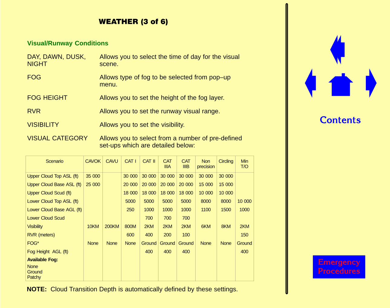
��������
������� �������
�������������
Visual/Runway Conditions
DAY, DAWN, DUSK,NIGHT
Allows you to select the time of day for the visualscene.
FOG Allows type of fog to be selected from pop–upmenu.
FOG HEIGHT Allows you to set the height of the fog layer.
RVR Allows you to set the runway visual range.
VISIBILITY Allows you to set the visibility.
VISUAL CATEGORY Allows you to select from a number of pre-definedset-ups which are detailed below:
Scenario CAVOK CAVU CAT I CAT II CATIIIA
CATIIIB
Nonprecision
Circling MinT/O
Upper Cloud Top ASL (ft) 35 000 30 000 30 000 30 000 30 000 30 000 30 000
Upper Cloud Base ASL (ft) 25 000 20 000 20 000 20 000 20 000 15 000 15 000
Upper Cloud Scud (ft) 18 000 18 000 18 000 18 000 10 000 10 000
Lower Cloud Top ASL (ft) 5000 5000 5000 5000 8000 8000 10 000
Lower Cloud Base AGL (ft) 250 1000 1000 1000 1100 1500 1000
Lower Cloud Scud 700 700 700
Visibility 10KM 200KM 800M 2KM 2KM 2KM 6KM 8KM 2KM
RVR (meters) 600 400 200 100 150
FOG* None None None Ground Ground Ground None None Ground
Fog Height AGL (ft) 400 400 400 400
Available Fog:NoneGroundPatchy
NOTE: Cloud Transition Depth is automatically defined by these settings.

��������
������� �������
��������������
SURFACEROUGHNESSCONTAMINATION
Allow you to set up the runway conditions.
VISUAL SCENE Displays a pop-up menu to allow you to select thetype of visual scene.
FALLING SNOWBLOWING SNOWLIGHTNING
Select the associated effect on/off.
RAIN Displays a pop-up menu which allows you to selectthe level of rain intensity.
HAIL Displays a pop-up menu which allows you to selectthe level of hail intensity.
MARSHALLER Selects marshaller on/off.
ROUTED TRAFFIC Displays Routed Traffic page.
VISUAL ON Switches the visual display on/off.
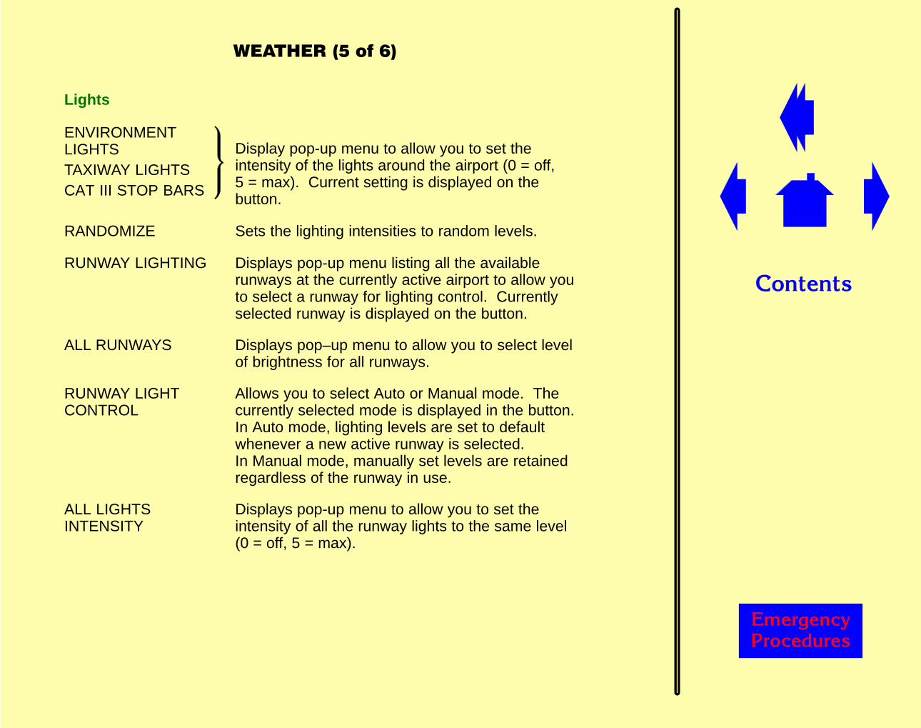
��������
������� �������
Display pop-up menu to allow you to set theintensity of the lights around the airport (0 = off,5 = max). Current setting is displayed on thebutton.
RANDOMIZE Sets the lighting intensities to random levels.
RUNWAY LIGHTING Displays pop-up menu listing all the availablerunways at the currently active airport to allow youto select a runway for lighting control. Currentlyselected runway is displayed on the button.
ALL RUNWAYS Displays pop–up menu to allow you to select levelof brightness for all runways.
RUNWAY LIGHTCONTROL
Allows you to select Auto or Manual mode. Thecurrently selected mode is displayed in the button.In Auto mode, lighting levels are set to defaultwhenever a new active runway is selected. In Manual mode, manually set levels are retainedregardless of the runway in use.
ALL LIGHTSINTENSITY
Displays pop-up menu to allow you to set theintensity of all the runway lights to the same level(0 = off, 5 = max).
�������������
Lights
ENVIRONMENTLIGHTSTAXIWAY LIGHTSCAT III STOP BARS
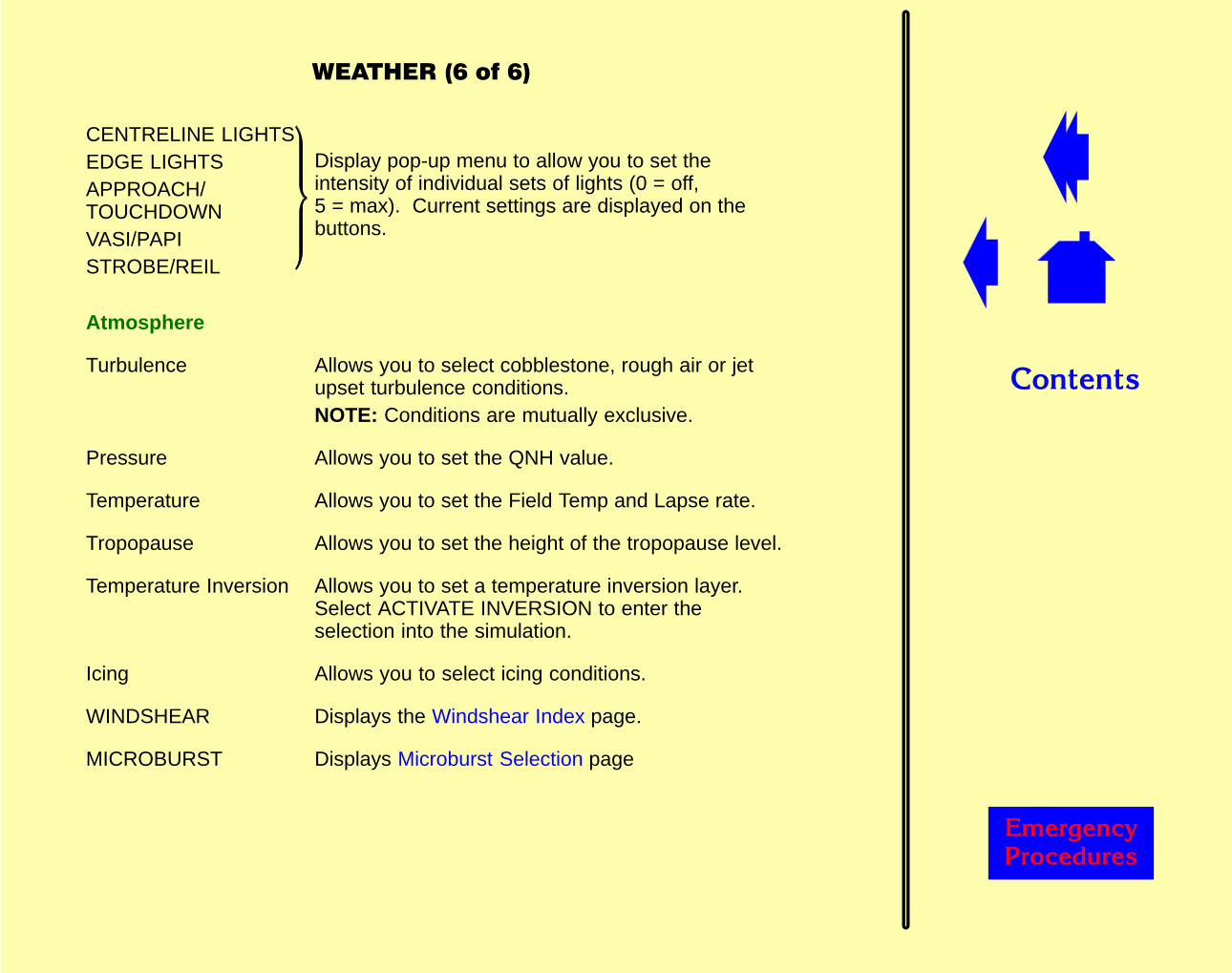
��������
������� �������
���������'���'
CENTRELINE LIGHTSEDGE LIGHTSAPPROACH/TOUCHDOWNVASI/PAPISTROBE/REIL
Display pop-up menu to allow you to set theintensity of individual sets of lights (0 = off,5 = max). Current settings are displayed on thebuttons.
Atmosphere
Turbulence Allows you to select cobblestone, rough air or jetupset turbulence conditions.NOTE: Conditions are mutually exclusive.
Pressure Allows you to set the QNH value.
Temperature Allows you to set the Field Temp and Lapse rate.
Tropopause Allows you to set the height of the tropopause level.
Temperature Inversion Allows you to set a temperature inversion layer.Select ACTIVATE INVERSION to enter theselection into the simulation.
Icing Allows you to select icing conditions.
WINDSHEAR Displays the Windshear Index page.
MICROBURST Displays Microburst Selection page
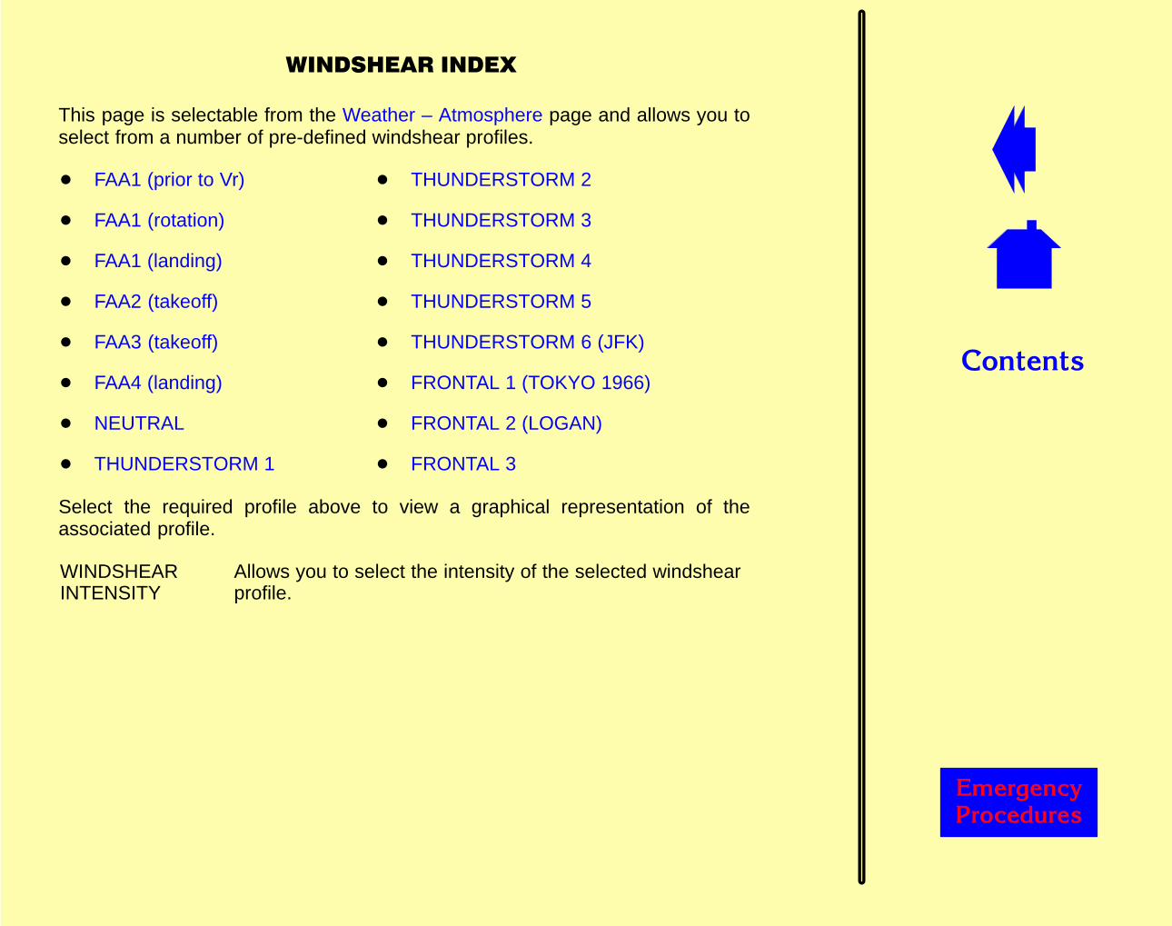
��������
������� �������
���������������
This page is selectable from the Weather – Atmosphere page and allows you toselect from a number of pre-defined windshear profiles.
� FAA1 (prior to Vr) � THUNDERSTORM 2
� FAA1 (rotation) � THUNDERSTORM 3
� FAA1 (landing) � THUNDERSTORM 4
� FAA2 (takeoff) � THUNDERSTORM 5
� FAA3 (takeoff) � THUNDERSTORM 6 (JFK)
� FAA4 (landing) � FRONTAL 1 (TOKYO 1966)
� NEUTRAL � FRONTAL 2 (LOGAN)
� THUNDERSTORM 1 � FRONTAL 3
Select the required profile above to view a graphical representation of theassociated profile.
WINDSHEARINTENSITY
Allows you to select the intensity of the selected windshearprofile.

��������
������� �������
������������
��� ����� ��������
��� ����������
������������
Windshear is activated when aircraft descends through 500 feet.
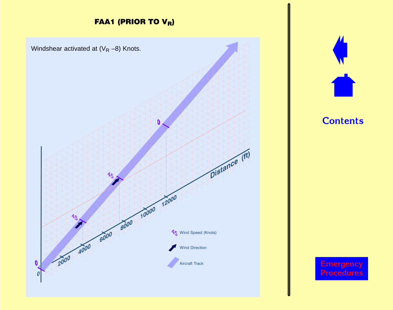
��������
������� �������
������������
��� ����� ��������
��� ����������
����������������
Windshear activated at (VR –8) Knots.
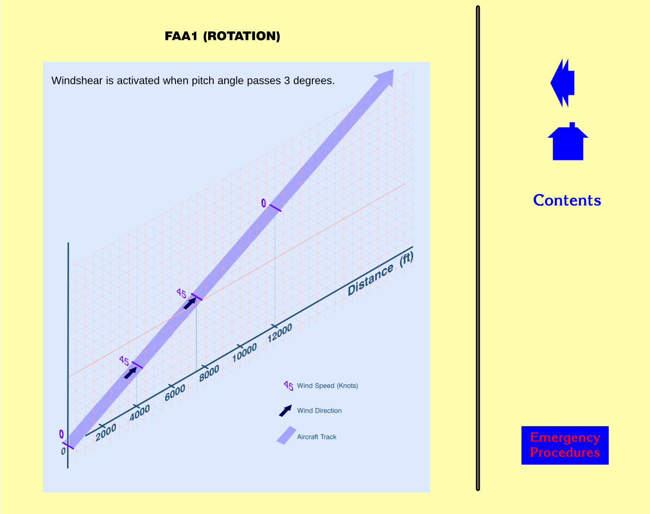
��������
������� �������
������������
��� ����� ��������
��� ����������
�������������
Windshear is activated when pitch angle passes 3 degrees.
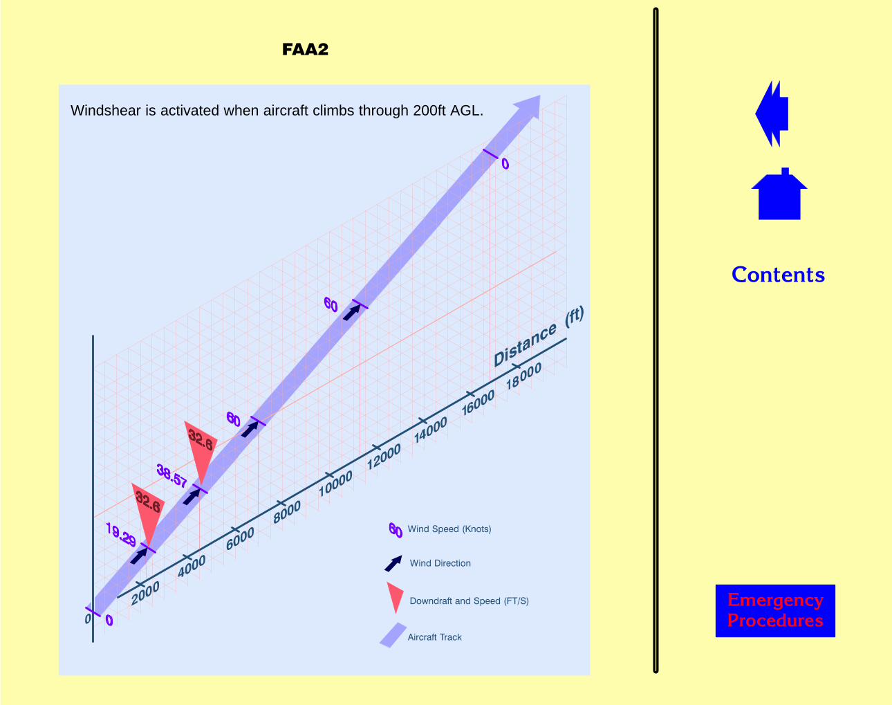
��������
������� �������
������������
��� ����� ��������
��� ����������
���� ������� ����� ������
����
Windshear is activated when aircraft climbs through 200ft AGL.
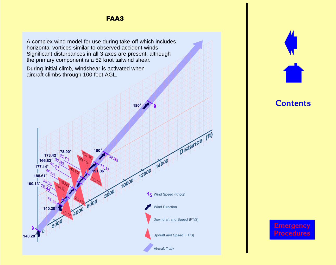
��������
������� �������
������������
��� ����� ��������
��� ����������
����
����
�������
���� ������� ����� ������
�� ������� ����� ������
������
������
�����������
�������
�����
�������
�������
���"
A complex wind model for use during take-off which includeshorizontal vortices similar to observed accident winds.Significant disturbances in all 3 axes are present, althoughthe primary component is a 52 knot tailwind shear.
During initial climb, windshear is activated whenaircraft climbs through 100 feet AGL.
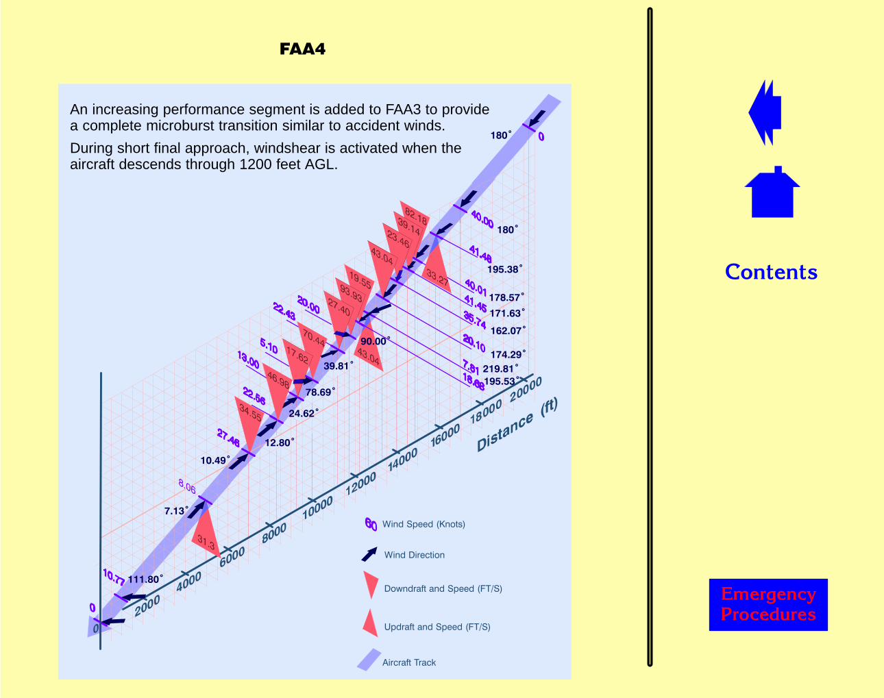
��������
������� �������
������������
��� ����� ��������
��� ����������
���� ������� ����� ������
�� ������� ����� ������
�������
����
������
����
�����
�����
������
������
�������
������
�����
�����
������
�����
�������
����
����
���#
An increasing performance segment is added to FAA3 to providea complete microburst transition similar to accident winds.
During short final approach, windshear is activated when theaircraft descends through 1200 feet AGL.

��������
������� �������
������������
��� ����� ��������
�����
���
���
���
�����
�����
���
�����
���
���
���
���
���
���
���
�����
��� ������������ �������
�������
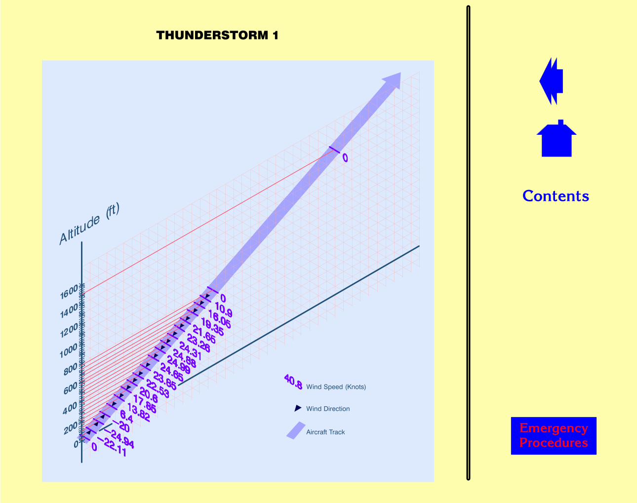
��������
������� �������
������������
��� ����� ��������
��� ����������
�������������
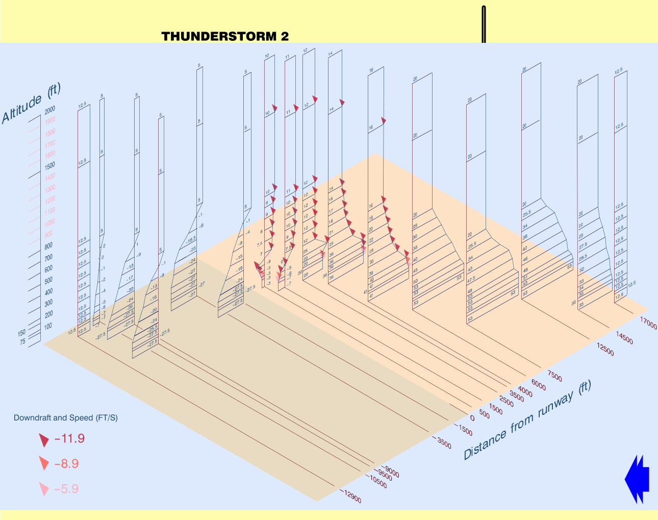
��������
������� �������
��������������
���� ������� ����� ������
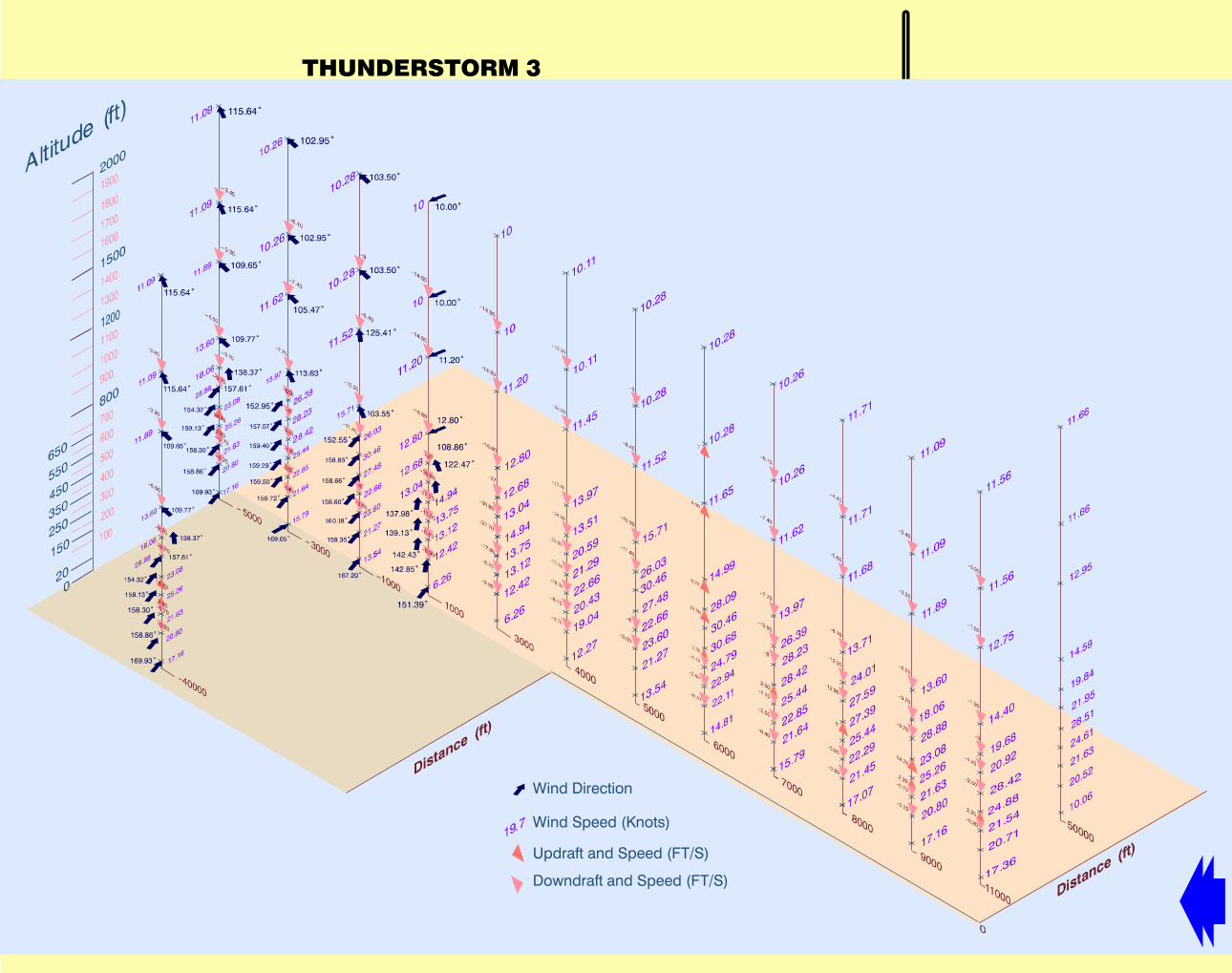
��������
������� �������
�������������"
���� ������� ����� ������
��� ����� ��������
��� ����������
�� ������� ����� ������

��������
������� �������
�������������#
���� ������� ����� ������
��� ����� ��������
��� ����������
�� ������� ����� ������
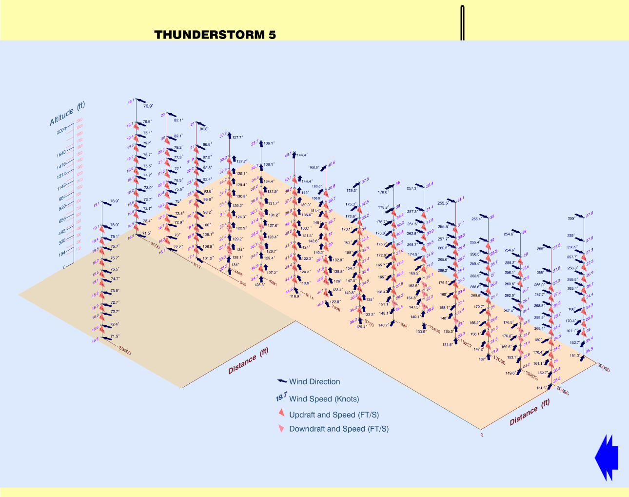
��������
������� �������
��������������
���� ������� ����� ������
��� ����� ��������
��� ����������
�� ������� ����� ������
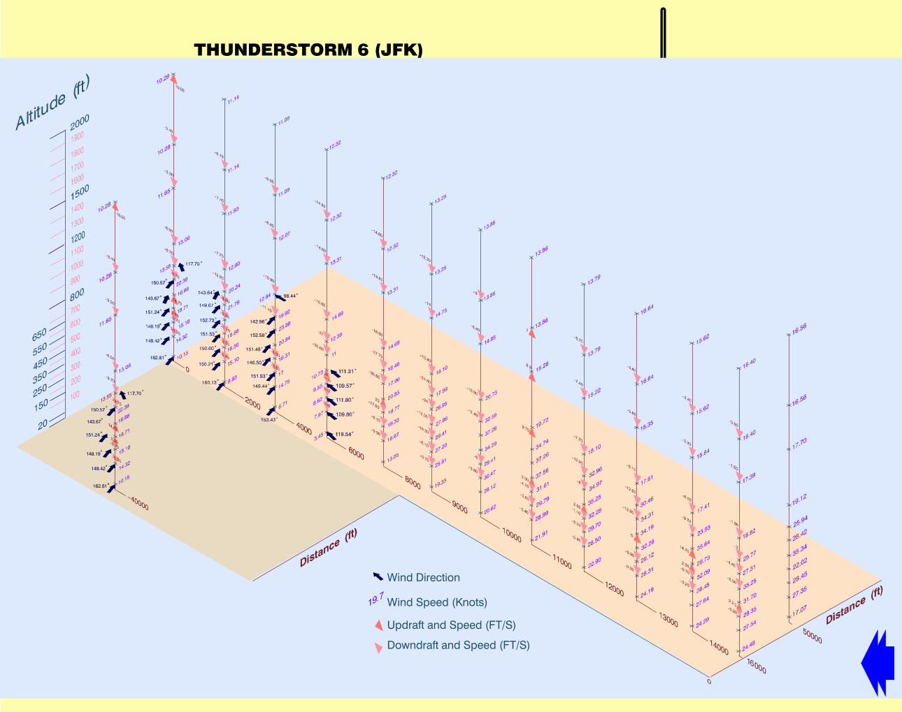
��������
������� �������
�������������'��+��
���� ������� ����� ������
��� ����� ��������
��� ����������
�� ������� ����� ������
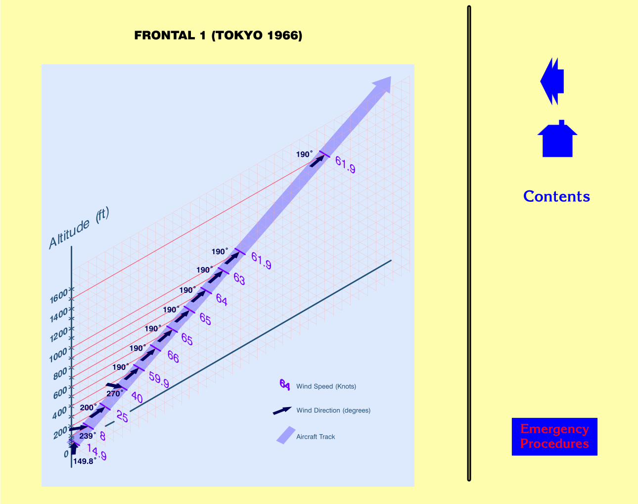
��������
������� �������
������������
��� ����� ��������
��� ������������ �������
����
��
���
���
������
����
����
����
����
����
����
����
����������������)''

��������
������� �������
������������
��� ����� ��������
��� ������������ �������
��
����
����
����
�����
��
��
��
��
��
��
����
����
����������������
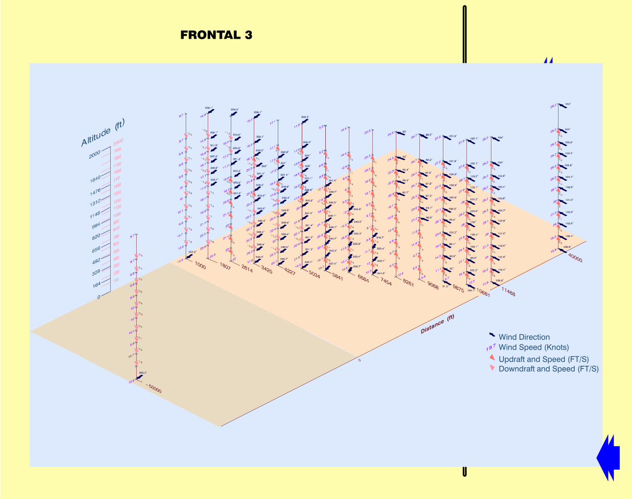
��������
������� �������
��������"
���� ������� ����� ������
��� ����� ��������
��� ����������
�� ������� ����� ������

��������
����������������$��%�������
The following safety features and equipment are provided on the simulator:
� Emergency Stop switch, which removes all electrical and hydraulic powerfrom the simulator, causing the simulator to settle to the access position to allowyou to evacuate the flight deck.
� Emergency Exit. A kick-out panel is provided in the rear door to allow you toevacuate the flight deck if the door will not open.
� Escape Ropes. Two escape ropes are provided, one on each side of the rearwalkway to allow you to descend from the simulator if the drawbridge fails tocome down.
� Fire Extinguishers. Two fire extinguishers are provided, one adjacent to therear door and one on the flight deck (as aircraft).
� Fire Detection. If a fire detector is activated, audible and visual warnings areinitiated. If the potential hazard is severe, electrical and hydraulic power isremoved from the simulator which settles into the access position to allow allpersonnel on board to evacuate the flight deck.
� Fire Suppression System (optional), which will protect the simulatorequipment by discharging a gas to extinguish a fire. If the gas is discharged,a continuous fire alarm will sound.
WARNING: The system must be set to manual operation when there arepersonnel present within the simulator building. Only set thesystem to automatic when the simulator is to be leftunattended.
The simulator must be evacuated immediately following thedischarge of fire suppression gas.
� Warning Signs. Must be read and meaning understood.
� Interlocks. Safety interlocks are fitted to the motion system, control loadingsystem and hydraulic power unit (HPU) to ensure that the systems cannot beoperated unless it is safe to do so. If any of the interlocks are opened, hydraulicpower is removed from the simulator which settles to the access position. Theinterlock must be closed before the motion and control loading systems can bere-engaged.
������� �������
������ ���������

��������
������������������
The following safety precautions must be observed when operating the simulator:
� Ensure all personnel are fully conversant with:
– The Safety Features and Equipment and with the Emergency Procedures.
– The position that the crew, instructors and observers seats and moveableaircraft panel must be placed in to clear the crew exit route.
� Before entering the simulator, did you check with the maintenance techniciansthat:
– The simulator was safe to enter.
– There were no personnel in areas of the simulator where they could beexposed to hazards when the motion and control loading systems areengaged.
– The fire suppression system (if fitted) was set to manual.
� Before starting the training exercise, ensure that:
– All personnel are seated with the seat belt fastened.
– All personal belongings and loose items are securely stowed.
� During the training exercise, ensure that all personnel remain seated with seatbelt fastened until the simulator settles to the access position.
������� �������
�������������

��������
��������������������������
Emergency
If an emergency occurs on the simulator:
� Press EMERGENCY STOP button. All personnel must remain seated andstrapped in.
– Electrical and hydraulic power is removed from simulator.
– Emergency lighting comes on.
– Simulator settles to access position.
� Once the simulator has reached the access position, all personnel releasestraps and remove headsets and oxygen masks (if worn).
� All seats and moveable panels must be moved to clear the exit route.
� Open rear door.
– If door will not open, kick out the lower panel of the door (markedEMERGENCY EXIT – PUSH).
� All personnel exit flight deck and leave simulator via the drawbridge.
– If drawbridge is not down, press DRAWBRIDGE LOWER switch on safetyrail adjacent to the gate to lower drawbridge.
– If drawbridge still fails to come down, use escape ropes located in the sidewalkway to descend from the simulator.
� When all flight crew have evacuated the simulator bay, liaise with maintenancestaff before resuming training.
Fire Detected
When a fire is detected the following occurs:
– Alarm sounds.
– Red beacon flashes.
– Electrical and hydraulic power is removed from simulator.
������ ���������
�������������
��������
���������������������������
– Emergency lighting comes on.
– Simulator settles to access position.
� Evacuate the simulator as for an Emergency.
Fire Suppression
� The simulator must be evacuated immediately following the discharge of firesuppression gas.
� Gas discharge can follow a continuous fire alarm tone.
Complete Power Loss
If a complete power loss occurs:
– Electrical and hydraulic power is removed from the simulator.
– Emergency lighting comes on.
– Simulator settles to access position.
� Call maintenance and establish cause of power failure and whether it isnecessary to evacuate the simulator.
� If evacuation is required, leave as normal.
Hydraulic Power Loss
If an hydraulic power loss occurs:
– Controls go slack and do not respond to flight crew inputs.
– Simulator settles to access position.
� Call maintenance and establish cause of power failure and whether it isnecessary to evacuate the simulator.
� If evacuation is required, leave as normal.
������ ���������
�������������
��������
������� �������
������,,,
Document Number: 61 434 716 -104
Revision: B
Date: February 2006
� Thales Training & Simulation Limited 2006 All rights reserved.
This document contains proprietary information which shall not be reproduced ortransferred to other documents or disclosed for any other purpose without thewritten permission of Thales Training & Simulation Limited (TT&S).
TT&S shall not be liable for any damages or losses whatsoever arising from the useof Technical Publications which have been in any way altered or modified other thanby TT&S.