instrument state recognition and tracking for effective
TRANSCRIPT
Instrument State Recognition and Tracking for
Effective Control of Robotized Laparoscopic
Systems
Manish Sahu, Daniil Moerman, and Philip Mewes
Siemens AG, Healthcare Sector, Forchheim, Germany
Email: [email protected]
Peter Mountney
Siemens Corporation, Corporate Technology, Princeton, NJ, USA
Georg Rose Otto-von-Guericke University Magdeburg
Abstract—Surgical robots are an important component for
delivering advanced paradigm shifting technology such as
image guided surgery and navigation. However, for robotic
systems to be readily adopted into the operating room they
must be easy and convenient to control and facilitate a
smooth surgical workflow. In minimally invasive surgery,
the laparoscope may be held by a robot but controlling and
moving the laparoscope remains challenging. It is disruptive
to the workflow for the surgeon to put down the tools to
move the robot in particular for solo surgery approaches.
This paper proposes a novel approach for naturally
controlling the robot mounted laparoscope’s position by
detecting a surgical grasping tool and recognizing if its state
is open or close. This approach does not require markers or
fiducials and uses a machine learning framework for tool
and state recognition which exploits naturally occurring
visual cues. Furthermore a virtual user interface on the
laparoscopic image is proposed that uses the surgical tool as
a pointing device to overcome common problems in depth
perception. Instrument detection and state recognition are
evaluated on in-vivo and ex-vivo porcine datasets. To
demonstrate the practical surgical application and real time
performance the system is validated in a simulated surgical
environment.
Index Terms—instrument tracking, laparoscopic surgery,
machine learning, surgical robotics, visual servoing
I. INTRODUCTION
Surgical robots have greatly changed the way many
procedures are performed. However, there are still a large
number which could benefit from robotic platforms and
the advanced imaging they can facilitate. One of the
barriers for integrating robotics into the operating room
(OR) is robotic control. Fully autonomous control has
regulatory challenges and therefore current research
focuses on developing intuitive control interfaces which
Manuscript received May 11, 2015; revised October 21, 2015.
enhance surgical workflow in the challenging OR
environment.
For minimally invasive abdominal procedures, having
a robot with a small footprint which can control the
laparoscope has been a goal for long time [1], [2]. The
key benefit is to facilitate solo surgery. To control the
laparoscope’s motion a number of solutions have been
proposed. A joystick [3] can be used, but this requires the
surgeon to put down their tools eventually. The AESOP
system [1] uses pre-defined voice commands and the
EndoAssist [2] system uses head gestures captured from a
tracker mounted on the surgeon’s head. [4] introduces the
concept of Gaze contingent control and [5] proposes a
fully automated motion compensation system.
Translating these approaches to the OR can be
challenging because they are either not well suited to the
OR environment (noisy, dynamic, space constrained) or
the surgical workflow. Robotic control should be
instinctive and fit seamlessly into the workflow without
introducing additional time consuming tasks such as
manual interaction.
A promising area of research is the application of
visual servoing, where surgical instruments are detected
in the laparoscopic image and used to guide the robot’s
movements. This is attractive because the surgeon
already uses the tools and is comfortable controlling them,
it does not require additional hardware, and there is little
disruption to the surgical workflow. Such systems are
comprised of two components: instrument
detection/tracking and robot control.
Instrument detection can be simplified with markers or
fiducials [6] but as this requires modifying hardware, it is
preferable to use natural image feature. Color space
features such as HSV with saturation enhancement [7]
can be used to segment tools but it may be sensitive to
changes in lighting. In [8] HSV is combined with Bayes
classifier to detect tools parts and the type of instrument
is detected by comparing against 3D models. 3D models
can be used to improve instrument detection [9] and
33
International Journal of Mechanical Engineering and Robotics Research Vol. 5, No. 1, January 2016
doi: 10.18178/ijmerr.5.1.33-38© 2016 Int. J. Mech. Eng. Rob. Res.
specific parts of articulated instruments and fuse these in
3D using stereo. Such approaches require a 3D model or
are focused on detecting the pose of the instrument but
not the state (open or close grasper).
Current vision based robotic controlled laparoscopic
systems [5]-[13] work by localizing the instrument
position in 2D, planning a path and moving the robot. For
controlling the depth, the geometrical relations between
the instrument [13] or the relation between the visible
tool/tools and the size of the whole scene [11], [12] are
utilized. Although the point may be defined by a tool but
this can cause problems; first the depth can be hard to
estimate accurately, secondly the end position of the
laparoscope may not have the desired field of view so this
approach to navigation is less intuitive.
This paper proposes an intuitive robotic navigation
system. It enables the surgeon to move a laparoscopic
camera by detecting and tracking the instruments in the
laparoscopic video. It does not require additional
hardware, fiducials or markers. Machine learning is used
to robustly detect surgical instruments and a novel
intuitive navigation system is proposed. Additionally we
explore the feasibility of using surgical instrument state
recognition to improve surgical workflow. Instrument
detection and state recognition are evaluated on in-vivo
and ex-vivo porcine dataset and the robotic navigation
system is validated in a simulated surgical environment.
II. SYSTEM OVERVIEW
The system is comprised of a 7-axis Kuka LWR 5
robot holding a monocular HD laparoscope. The
laparoscope is inserted into the abdomen through a trocar
port and held by the laparoscopic robot. The operator
introduces a standard grasping or cutting instrument into
the abdomen though a second port and into the view of
the laparoscope. The robot control interface is overlaid on
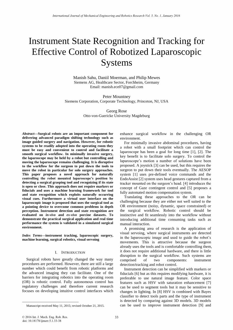
the live laparoscopic video stream to facilitate navigation.
An overview of the system is provided in Fig. 1.
Figure 1. Replica of system setup with robot with plastic porcine liver (up) and virtual interface (down)
III. ROBOT VIRTUAL CONTROL INTERFACE
A novel robot control interface is proposed which
provides a natural and intuitive navigation of the
laparoscope with four degrees of freedom. A simple and
effective solution to navigate laparoscope in/out along
optical axis is presented which does not rely on
estimating the pose or depth of the instrument or defining
a point in 3D.
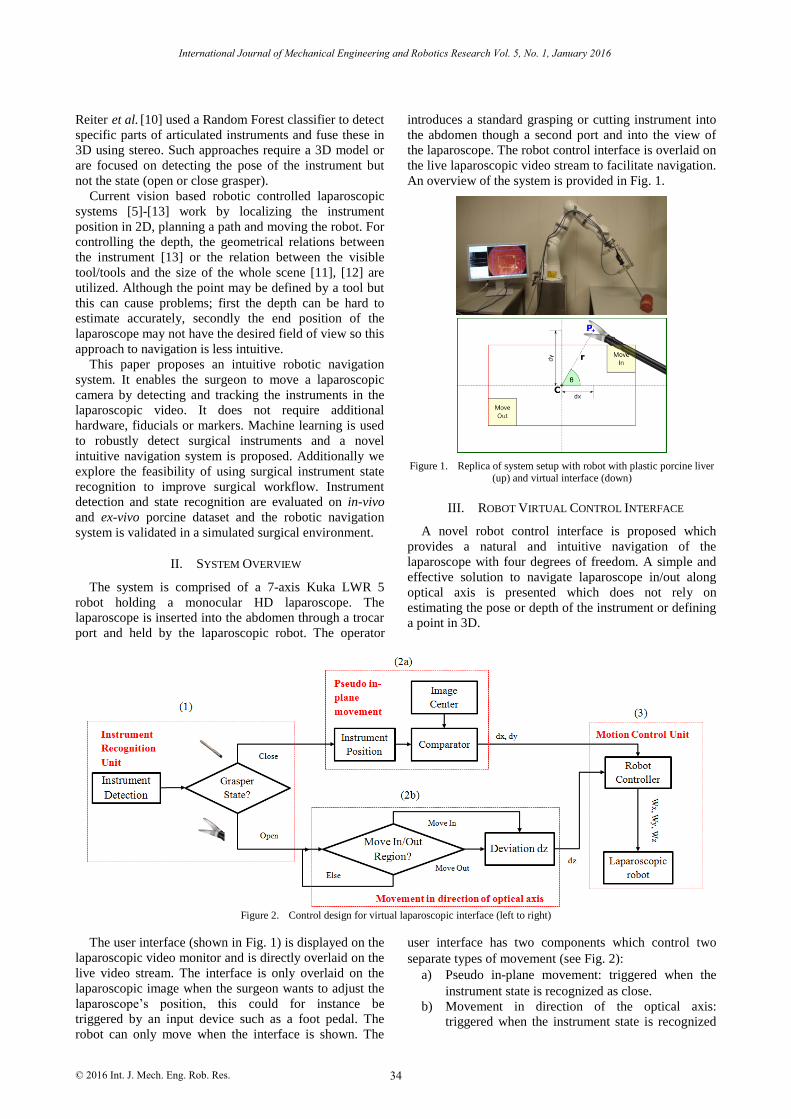
Figure 2. Control design for virtual laparoscopic interface (left to right)
The user interface (shown in Fig. 1) is displayed on the
laparoscopic video monitor and is directly overlaid on the
live video stream. The interface is only overlaid on the
laparoscopic image when the surgeon wants to adjust the
laparoscope’s position, this could for instance be
triggered by an input device such as a foot pedal. The
robot can only move when the interface is shown. The
user interface has two components which control two
separate types of movement (see Fig. 2):
a) Pseudo in-plane movement: triggered when the
instrument state is recognized as close.
b) Movement in direction of the optical axis:
triggered when the instrument state is recognized
34
International Journal of Mechanical Engineering and Robotics Research Vol. 5, No. 1, January 2016
Reiter et al. [10] used a Random Forest classifier to detect
© 2016 Int. J. Mech. Eng. Rob. Res.
as open and the instrument position is inside
predefined regions: move in and move out.
To prevent the robot from moving as soon as the user
interface is switched on the tracking process starts only if
the instrument is detected inside the rectangular start-up
region (red box of 640x640 pixels, see Fig. 1) and the
instrument state is open.
Pseudo in-plane movement corresponds to the natural
user navigation of moving the laparoscope up, down, left
and right. To the end user this appears to be in plane
motion, however because the laparoscope is inserted
through a trocar port it has a remote center of motion and
therefore it is not truly in-plane. Pseudo in plane
movement is triggered only when the instrument state is
detected as close. If the tool is in the open state the in-
plane robot movement is disabled. Once the instrument is
detected as close the deviations from the center of the
central region are computed (see Fig. 1).
𝑑𝑥 = 𝑃(𝑥) − 𝐶(𝑥), 𝑑𝑦 = 𝑃(𝑦) − 𝐶(𝑦) (1)
Then these pixel deviations are transformed to the
robot rotational commands, Wx and Wy and transferred to
the robot.
𝑊𝑥 = 𝐺𝑥 × 𝑑𝑥, 𝑊𝑦 = 𝐺𝑦 × 𝑑𝑦 (2)
The controller gains 𝐺𝑥 and 𝐺𝑦 are added for smooth
displacement of the robot. The robot continues to move
until the detected tool state is close or the instrument
reaches center of image i.e. pixel deviation is zero.
Movement in direction of the optical axis of the
laparoscope corresponds to moving the laparoscope in
and out of the trocar port. The user interface defines two
regions shown in Fig. 1 and labelled as “Move in” and
“Move out”. If the tool is detected in these regions in the
open state position then the laparoscope will be
forwarded or reversed along the optical axis of the
laparoscopic camera with a predefined constant value dz
(see Fig. 2-2b). This constant value is then transformed to
the robot rotational commands of movement along optical
axis.
𝑊𝑧 = 𝐺𝑧 × 𝑑𝑧 (3)
where, Gz is the controller gain.
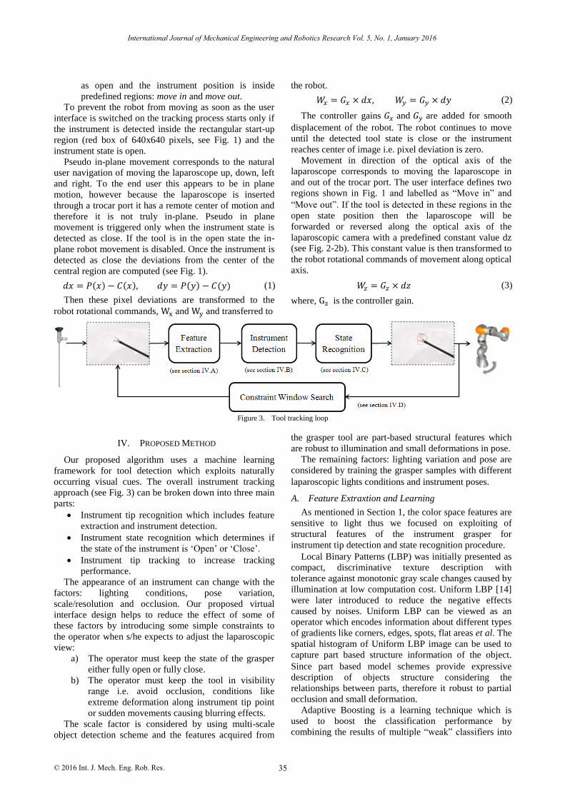
Figure 3. Tool tracking loop
IV. PROPOSED METHOD
Our proposed algorithm uses a machine learning
framework for tool detection which exploits naturally
occurring visual cues. The overall instrument tracking
approach (see Fig. 3) can be broken down into three main
parts:
Instrument tip recognition which includes feature
extraction and instrument detection.
Instrument state recognition which determines if
the state of the instrument is ‘Open’ or ‘Close’.
Instrument tip tracking to increase tracking
performance.
The appearance of an instrument can change with the
factors: lighting conditions, pose variation,
scale/resolution and occlusion. Our proposed virtual
interface design helps to reduce the effect of some of
these factors by introducing some simple constraints to
the operator when s/he expects to adjust the laparoscopic
view:
a) The operator must keep the state of the grasper
either fully open or fully close.
b) The operator must keep the tool in visibility
range i.e. avoid occlusion, conditions like
extreme deformation along instrument tip point
or sudden movements causing blurring effects.
The scale factor is considered by using multi-scale
object detection scheme and the features acquired from
the grasper tool are part-based structural features which
are robust to illumination and small deformations in pose.
The remaining factors: lighting variation and pose are
considered by training the grasper samples with different
laparoscopic lights conditions and instrument poses.
A. Feature Extraxtion and Learning
As mentioned in Section 1, the color space features are
sensitive to light thus we focused on exploiting of
structural features of the instrument grasper for
instrument tip detection and state recognition procedure.
Local Binary Patterns (LBP) was initially presented as
compact, discriminative texture description with
tolerance against monotonic gray scale changes caused by
illumination at low computation cost. Uniform LBP [14]
were later introduced to reduce the negative effects
caused by noises. Uniform LBP can be viewed as an
operator which encodes information about different types
of gradients like corners, edges, spots, flat areas et al. The
spatial histogram of Uniform LBP image can be used to
capture part based structure information of the object.
Since part based model schemes provide expressive
description of objects structure considering the
relationships between parts, therefore it robust to partial
occlusion and small deformation.
Adaptive Boosting is a learning technique which is
used to boost the classification performance by
combining the results of multiple “weak” classifiers into
35
International Journal of Mechanical Engineering and Robotics Research Vol. 5, No. 1, January 2016
© 2016 Int. J. Mech. Eng. Rob. Res.
a single “strong” classifier. In our approach, we expect a
noisy image due to specular reflections and therefore we
use Gentle AdaBoost [15] because it uses Newton
stepping instead of exact optimization at each step and
thus provide better performance when the training data is
noisy and has outliers [16]. Decision trees are fast to learn
and non-linear in nature and thus often used as weak
learners for boosting.
For computation of structural features, the image is
first converted to gray scale, and then the contrast of the
image is enhanced by histogram equalization followed by
labelling the image with Uniform Local Binary Pattern
(ULBP) operator. Once the image is labeled, it is divided
into 2x2 sub-windows and histogram for each sub-
window is concatenated in a single 1-D histogram (see
Fig. 4). These part based structure feature descriptors are
then trained through boosted decision trees.
Figure 4. Feature extraction pipeline
B. Instrument Detection
The instrument detection step comprises of scanning
the laparoscopic image at multiple scales and locations by
using sliding window object detection scheme. Features
described above are extracted from each window patch
and classified into “tool” and “no tool”. Since our
detection algorithm searches for different scales and
location, multiple detections would occur around
instrument tip. For reducing multiple detections to a
single detection, we inherited the design of integration of
multiple detections from [17] and assigned the regression
value of the AdaBoost classifier as weights to the
corresponding detected windows.
C. Instrument State Recognition
Instrument state recognition is a critical part of the
proposed novel approach to robotic control. Once the tool
is detected an additional classification is performed on
the detected tool window to determine the state of the
tool i.e. open or close grasper. The state classification is
based on same set of part-based structure features
mentioned above and using a second Gentle AdaBoost
classifier.
D. Instrument Tracking
After the instrument tip is detected, a window
(320x320 pixels in the native scale of resolution
1920x1080 pixels) is created around the instrument tip
location and instrument detection is performed inside this
constraint window for the next frame.
V. EXPERIEMENTS
In order to demonstrate the practical application of the
proposed robotic navigation system a number of
validation experiments were performed to evaluate the 1)
instrument detection and state recognition and 2)
feasibility of virtual interface based robot navigation
system.
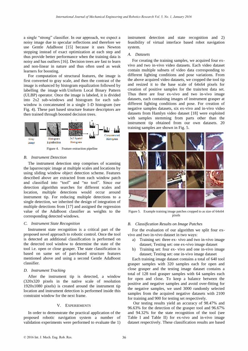
A. Datasets
For creating the training samples, we acquired four ex-
vivo and two in-vivo video datasets. Each video dataset
contain multiple subsets of video data corresponding to
different lighting conditions and pose variations. From
the above acquired video datasets, we cropped the tool tip
and resized it to the base scale of 64x64 pixels for
creation of positive samples for the train/test data set.
Thus there are four ex-vivo and two in-vivo image
datasets, each containing images of instrument grasper at
different lighting conditions and pose. For creation of
negative samples datasets, six ex-vivo and in-vivo video
datasets from Hamlyn video dataset [18] were exploited
with samples stemming from parts other than the
instrument tip obtained from our own datasets. 20
training samples are shown in Fig. 5.
Figure 5. Example training image patches cropped to as size of 64x64
pixels
B. Classification Results on Image Patches
For the evaluation of our algorithm we split four ex-
vivo and two in-vivo dataset in two ways:
a) Training set: three ex- vivo and two in-vivo image
dataset; Testing set: one ex-vivo image dataset
b) Training set: four ex- vivo and one in-vivo image
dataset; Testing set: one in-vivo image dataset
Each training image dataset contains a total of 640 tool
grasper samples with 320 samples each for open and
close grasper and the testing image dataset contains a
total of 128 tool grasper samples with 64 samples each
for open and close. To keep a balance between the
positive and negative samples and avoid over-fitting for
the negative samples, we used 3000 randomly selected
samples from the acquired negative datasets with 2100
for training and 900 for testing set respectively.
Our testing results yield an accuracy of 98.47% and
96.63% for the detection of the grasper tool and 96.67%
and 94.32% for the state recognition of the tool (see
Table I and Table II) for ex-vivo and in-vivo image
dataset respectively. These classification results are based
36
International Journal of Mechanical Engineering and Robotics Research Vol. 5, No. 1, January 2016
© 2016 Int. J. Mech. Eng. Rob. Res.
on AdaBoost classifiers with decision trees as weak
learners (discussed in section IV.A). Other classifiers:
Random Forest and Linear Support Vector Machine are
considered but not mentioned as they are outperformed
by AdaBoost.
TABLE I. CLASSIFICATION RESULT ON EX-VIVO IMAGE DATA
Data
-set
Detection
Type Precision Recall Specificity Accuracy
ex-
vivo (a)
Tool - No Tool
89.98% 85.29% 98.96% 98.47%
Open -
Close 98.48% 95.59% 98.08% 96.67%
TABLE II. CLASSIFICATION RESULT ON IN-VIVO IMAGE DATA
Data-set
Detection Type
Precision Recall Specificity Accuracy
in-
vivo
(b)
Tool -
No Tool 85.00% 77.27% 98.61% 96.63%
Open -
Close 94.87% 92.50% 95.83% 94.32%
C. Reatl-Time Ex-Vivo Experiment
The robotic navigation system was evaluated in a
replica surgical environment. In this experiment a
laparoscope is mounted on the Kuka LWR 5 and a freshly
resected pig liver is placed in the field of view of the
laparoscope. The laparoscope acquires images of
1920x1080 pixels resolution at 25 frames per second. A
remote center of motion was simulated to replicate the
effect of the port on the laparoscope and a surgical
grasper was use as the instrument. A non-expert user was
given the task of control by using the surgical instrument.
The user was able to naturally control the robot’s motions
in all degrees of freedom with a shallow learning curve.
To further validate the strength of our approach in this
experimental setup, we analyzed a total of 692 frames.
After running our proposed algorithm for tool detection, a
total of 589 were recognized with 58 false detections as
shown in Table III. Some of the instances of the live
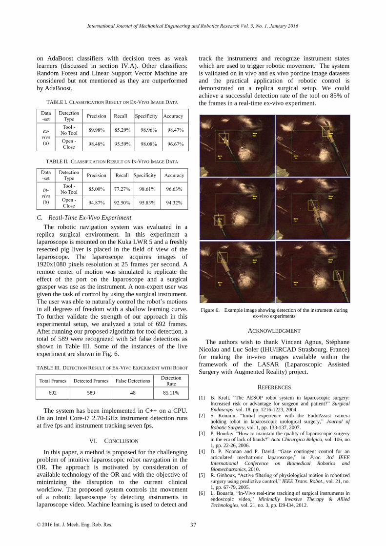
experiment are shown in Fig. 6.
TABLE III. DETECTION RESULT OF EX-VIVO EXPERIMENT WITH ROBOT
Total Frames Detected Frames False Detections Detection
Rate
692 589 48 85.11%
The system has been implemented in C++ on a CPU.
On an Intel Core-i7 2.70-GHz instrument detection runs
at five fps and instrument tracking seven fps.
VI. CONCLUSION
In this paper, a method is proposed for the challenging
problem of intuitive laparoscopic robot navigation in the
OR. The approach is motivated by consideration of
available technology of the OR and with the objective of
minimizing the disruption to the current clinical
workflow. The proposed system controls the movement
of a robotic laparoscope by detecting instruments in
laparoscope video. Machine learning is used to detect and
track the instruments and recognize instrument states
which are used to trigger robotic movement. The system
is validated on in vivo and ex vivo porcine image datasets
and the practical application of robotic control is
demonstrated on a replica surgical setup. We could
achieve a successful detection rate of the tool on 85% of
the frames in a real-time ex-vivo experiment.
Figure 6. Example image showing detection of the instrument during ex-vivo experiments
ACKNOWLEDGMENT
The authors wish to thank Vincent Agnus, Stéphane
Nicolau and Luc Soler (IHU/IRCAD Strasbourg, France)
for making the in-vivo images available within the
framework of the LASAR (Laparoscopic Assisted
Surgery with Augmented Reality) project.
REFERENCES
[1] B. Kraft, “The AESOP robot system in laparoscopic surgery: Increased risk or advantage for surgeon and patient?” Surgical
Endoscopy, vol. 18, pp. 1216-1223, 2004.
[2] S. Kommu, “Initial experience with the EndoAssist camera holding robot in laparoscopic urological surgery,” Journal of
Robotic Surgery, vol. 1, pp. 133-137, 2007.
[3] P. Hourlay, “How to maintain the quality of laparoscopic surgery in the era of lack of hands?” Acta Chirurgica Belgica, vol. 106, no.
1, pp. 22-26, 2006.
[4] D. P. Noonan and P. David, “Gaze contingent control for an articulated mechatronic laparoscope,” in Proc. 3rd IEEE
International Conference on Biomedical Robotics and
Biomechatronics, 2010. [5] R. Ginhoux, “Active filtering of physiological motion in robotized
surgery using predictive control,” IEEE Trans. Robot., vol. 21, no.
1, pp. 67-79, 2005. [6] L. Bouarfa, “In-Vivo real-time tracking of surgical instruments in
endoscopic video,” Minimally Invasive Therapy & Allied
Technologies, vol. 21, no. 3, pp. l29-l34, 2012.
37
International Journal of Mechanical Engineering and Robotics Research Vol. 5, No. 1, January 2016
© 2016 Int. J. Mech. Eng. Rob. Res.
[7] C. Doignon, “Real-Time segmentation of surgical instruments inside the abdominal cavity using a joint hue saturation color
feature,” Real-Time Imaging, vol. 11, no. 5, pp. 429-442, 2005.
[8] S. Speidel, “Automatic classification of minimally invasive instruments based on endoscopic image sequences,” SPIE Medical
Imaging. International Society for Optics and Photonics, 2009.
[9] Z. Pezzementi, “Articulated object tracking by rendering consistent appearance parts,” in Proc. International Conference on
Robotics and Automation, Kobe, Japan, May 12-17, 2009, pp.
3940-3947. [10] A. Reiter, “Feature classification for tracking articulated surgical
tools,” in Medical Image Computing and Computer-Assisted
Intervention–MICCAI, Springer Berlin Heidelberg, 2012, pp. 592-600.
[11] S. Voros, “Automatic detection of instruments in laparoscopic
images: A first step towards high-level command of robotic endoscopic holders,” The International Journal of Robotics
Research, vol. 26, no. 11-12 , pp. 1173-1190, 2007.
[12] A. Casals and J. Amat, Automatic Guidance of an Assistant Robot in Laparoscopic Surgery, 1996.
[13] K. T. Song and C. J. Chen, “Autonomous and stable tracking of
endoscope instrument tools with monocular camera,” in Proc.
IEEE/ASME International Conference on Advanced Intelligent Mechatronics, 2012.
[14] M. Pietikäinen, “Local binary patterns for still images,” in
Computer Vision Using Local Binary Patterns, Springer London, 2011, pp. 13-47.
[15] J. Friedman, et al., “Additive logistic regression: A statistical view
of boosting (with discussion and a rejoinder by the authors),” The Annals of Statistics, vol. 28, no. 2, pp. 337-407, 2000.
[16] R. Lienhart, A. Kuranov, and V. Pisarevsky, “Empirical analysis
of detection cascades of boosted classifiers for rapid object detection,” in Pattern Recognition, Springer Berlin Heidelberg,
2003, pp. 297-304.
[17] P. Viola and J. Michael, “Rapid object detection using a boosted cascade of simple features,” in Proc. IEEE Computer Society
Conference on Computer Vision and Pattern Recognition, 2001,
vol. 1. [18] P. Mountney, “Three-dimensional tissue deformation recovery and
tracking: Introducing techniques based on laparoscopic or
endoscopic images,” IEEE Signal Processing Magazine, vol. 27, no. 4, pp. 14-24, July 2010.
38
International Journal of Mechanical Engineering and Robotics Research Vol. 5, No. 1, January 2016
© 2016 Int. J. Mech. Eng. Rob. Res.