integrated automation system case...
TRANSCRIPT
King Saud University
College Of Engineering
Department of Industrial Engineering
INTEGRATED AUTOMATION SYSTEM CASE STUDY
By:
Ibraheem Khaled Addoweesh
Submitted in partial fulfillment of the requirement for the Degree of
Bachelor of Science in Industrial Engineering College of Engineering,
king Saud University
Riyadh
1433 - 1434 H
(Second Semester)

2
We hereby approve the report entitled:
Integrated Automation System Case Study
Prepared by: Ibraheem K. Addoweesh
(426-105-585)
COMMITTEE MEMBERS:
Advisor: Prof. Ali M. Al-Samhan
Signature _____________
Examiner: Prof. Abdulaziz M. Al-Tamimi
Signature _____________
Date:_____________

3
Acknowledgement
I have been looking forward to write the acknowledgment, not only because it comes at a time
when my research is completed, but also because it gives me a chance to thank the people who
helped me to complete this work.
I would like to express my deep thanks and gratitude to prof. Ali M. Al-Samhan under whom
main supervision the present project has been undertaken. His generous discussion, continues
guidance and enthusiastic support throughout the different made the project to appear in its final
form.
I am also indebted to my family for their support and encouragement.
Ibraheem K. Addoweesh

4
Table of Content
Acknowledgement ........................................................................................................................................ 3
List of Figures ............................................................................................................................................... 5
Abstract (English) ......................................................................................................................................... 7
Abstract (Arabic) .......................................................................................................................................... 8
Chapter 1: Integrated Automation System .................................................................................................... 9
1.1 Background ................................................................................................................................... 9
1.2 Benefits of total integrated automation system ............................................................................. 9
1.3 General View of Integrated Automation System and automation levels .................................... 10
1.4 Simatic S7-300 PLC: .................................................................................................................. 11
1.5 Problem definition ...................................................................................................................... 13
1.6 Project objectives ........................................................................................................................ 14
1.7 Project work tasks ....................................................................................................................... 15
1.8 Project methodology ................................................................................................................... 15
Chapter 2: Introduction to Industrial Robotics ........................................................................................... 18
2.1 Industrial Robotic Definition and types: ..................................................................................... 18
2.2 Technical and parameters of industrial robot: ............................................................................. 20
2.3 Robot programming and interfaces: ............................................................................................ 22
2.4 End-of-arm Tooling: ................................................................................................................... 24
2.5 Controlling Movement: ............................................................................................................... 24
2.6 Typical Programming: ................................................................................................................ 25
Chapter 3: Project Objectives and Methodology ....................................................................................... 26
3.1 Automatic control system: .......................................................................................................... 26
3.2 Classification of control system based on time and resolution: .................................................. 27
3.3 Programmable logic controller: .................................................................................................. 29
3.4 Understanding Relay Ladder Logic Programming ..................................................................... 32
3.5 Basic Instructions of RLL ........................................................................................................... 35
3.6 Integrated automation system ..................................................................................................... 36
Chapter 4: 3D solid assembly model for CNC vertical milling machine .................................................... 37
4.1 Modeling the 3D machine strudcture .......................................................................................... 38
4.2 Modeling machine slides and its assembly ................................................................................. 42
4.3 CNC vertical machine assembly modeling ................................................................................. 44
Chapter 5: 3D solid assembly modeling for Manipulator ........................................................................... 45
5.1 Modeling manipulator slide D .................................................................................................... 47
5.2 Modeling the angular displacement (C) ...................................................................................... 50
5.3 Modeling the end-effect gripper (E) ........................................................................................... 51
5.4 Modeling steel welded bracket carrying the manipulator basement ........................................... 52

5
Chapter 6: 3D solid assembly modeling for integrated automation system structure ................................. 53
6.1 Manipulator Machine Sequence .................................................................................................. 54
6.2 Relay Ladder Logic program for given machine sequence......................................................... 68
6.3 Summery and Conclusion ........................................................................................................... 73
References: .................................................................................................................................................. 74
List of Figures
Figure 1.1 : Integrated automation system and automation levels................................................11
Figure 1.2 : SIMATIC and totally integrated automation system in Siemens..... .........................11
Figure 1.3 : SIMATIC S7-300 general layout............................................................ ..................12
Figure 1.4 : General layout and modules of the SIMATIC S7-300 system................................ 13
Figure 1.5 : CNC Vertical milling machine............................... ...................................................14
Figure 1.6 : Discrete control Cartesian robot to be integrated with CNC milling machine for
loading and unloading............................... .....................................................................................14
Figure 1.7 : Block diagram for suggested integrated automation system between pneumatic
manipulator, CNC milling machine, power clamping fixture and manipulator steel-welded
structure..........................................................................................................................................15
Figure 1.8 : Block diagram for project methodology ...................................................................17
Figure 2.1 : Industrial Robot in foundry process(left side) and in welding process in right side.18
Figure 2.2 : SCARA industrial robot.... ........................................................................................19
Figure 2.3 : Delta Industrial Robotic........................................................... .................................19
Figure 2.4 : Cattesian coordinate industrial robot....................................................... ..................20
Figure 2.5 : Industrial Robot programming and teaching pendent............................... ................24
Figure 3.1 : General layout of closed loop PID controller.................................................. ..........27
Figure 3.2 : Open (a) and closed loop (b) control systems............................................. ..............28
Figure 3.3 : Hopper control through discrete event system. .........................................................30
Figure 3.4 : Pneumatic cylinder position control problem.. .........................................................30
Figure 3.5 : Internal structure of a PLC.. ......................................................................................30
Figure 3.6 : Programming language for PLC for AND/OR
gates.......................................................31
Figure 3.7 : PLC Programming technique using PC computer through serial port......................31
Figure 3.8 : Scanning technique in PLC…………………….......................................................32
Figure 3.9 : Simple control circuit of a bell............................................................................... ...33
Figure 3.10: A typical industrial relay.................................. .........................................................34
Figure 3.11: Contact relay symbol........................................................... .....................................34
Figure 3.12: Output relay symbol.................................. ................................................................34
Figure 3.13: RLL for bell control circuit........................................................... ............................35

6
Figure 3.14: Main instructions in RLL.................................. .........................................................35
Figure 3.15: Control and RLL for AND Boolean operation ..........................................................36
Figure 3.16: Amended RLL using normally closed switch for switch SW2 ..................................36
Figure 4.1 : General layout for 3D assembly model for CNC Vertical milling machine.. ...........37
Figure 4.2 : General layout for 3D assembly model for CNC Vertical milling machine, explode
view........................................................... .....................................................................................38
Figure 4.3 : modeling Z-axis machine structure (a, c, d) and Z-axis slide motor (b)............... ....39
Figure 4.4 : Modeling machine Y-axis machine structure and machine bed (a), Machine box
frames (b,c, d)............................... .................................................................................................40
Figure 4.5 : Modeling machine structure base (a, b), controller cabinet (c) and Y-axis to base
(d). ..................................................................................................................................................41
Figure 4.6 : Modeling machine slides (X and Y) and its sub-assembly....................................... 42
Figure 4.7 : Modeling machine Y-axis machine structure and machine bed (a), Machine box
frames (b, c, d). ..............................................................................................................................43
Figure 4.8 : Modeling machine assembly with its slides (X, Y and Z) as well as machine glass
guards.. ...........................................................................................................................................44
Figure 5.1 : Modeling manipulator assembly with its slides (A, B,C,D and E.............................46
Figure 5.2 : Explode drawing manipulator assembly....................................................................47
Figure 5.3 : Modeling manipulator assembly with its slide (D)........................................... ........48
Figure 5.4 : Modeling manipulator slide (A).......................... ......................................................49
Figure 5.5 : Modeling the actuator having angular displacement (C).......................................... 50
Figure 5.6 : Modeling the pneumatic power gripper (E).................................. ............................51
Figure 5.7 : Modeling manipulator welded steel bracket with angle profile 35x35x5mm....... ...52
Figure 6.1 : Modeling manipulator welded steel bracket with angle profile 35x35x5mm... ........53
Figure 2.6 : (a) Slide D+ Moving toward CNC m/c, (b) Arm B+ forward position....................57
Figure 6.3 : (a) Gripper E- close gripper, (b) Fixture F+ open fixture.................................. .......58
Figure 2.6 : (a) Arm B- backward position, (b) Arm B rotation C+ counter clockwise ...............59
Figure 6.5 : (a) Arm B+ forward position, (b) Gripper E+ open gripper..................................... .60
Figure 6.6 : (a) Arm B- backward position, (b) Slide D- Moving outward CNC m/c ..................61
Figure 6.7 : (a) Arm B+ forward position, (b) Gripper E- close gripper ......................................62
Figure 6.8 : (a) Arm B- backward position, (b) Arm B rotation C- clockwise............................. 63
Figure 6.9 : (a) Slide D+ Moving toward CNC m/c, (b) Arm B+ forward position.................... 64
Figure 6.10: (a) Fixture F- close fixture, (b) Gripper E+ open gripper..................................... ....65
Figure 6.11: (a) Arm B- backward position, (b) Slide D- Moving outward CNC m/c..................66
Figure 6.12: Glass door G- close ...................................................................................................67
Figure 6.13: Raly ladder logic, flip-flop module.. .........................................................................70
Figure 6.14: Raly ladder logic, output module ..............................................................................71
Figure 6.15: Raly ladder logic, output module ..............................................................................72

7
Abstract Manufacturing processes are no longer seen as individual processes, but rather as integral
components of an entire production process. The new development now becomes the term of
total integrated automation environment which achieved with the help of ; one common
software environment that integrates all components and tasks into one uniform easy to use
system. A common data management (central database). A common communication between all
participating automation components.
Total integrated automation system is advance technology and commonly are monopolized by
modern industrial countries. Current project, provide a case study for integrated automation
system between manufacturing process (CNC vertical milling machine) and Cartesian pneumatic
manipulator used for loading and unloading workpiece to CNC vertical milling machine plus
power clamping fixture. The project objectives cover the following tasks
Model a 3D CAD system cover the integration system between discrete control Cartesian
robot and small recently retrofitted CNC Milling machine.
Identify the machine sequence tasks for pneumatic manipulator with CNC vertical milling
machine operation and evaluate them using CAD system. At the end, obtain all the important
dimensions required for manufacturing the welded structure joining the two sub-systems.
Write the Relay Ladder logic program to carry out the proposed manipulator movement
sequence.
Suggest the automation protocol between the two integrated automation sub-systems
Finally, it was concluded the propose system acceptable for development.

8
ملخص المشروع
بل عملية تكاملية بين مكونات عمليات اإلنتاج وخاصة التطور الحديث في ،لم يعد األسلوب الصناعي عمل مستقل
مجال التكامل الكلي.
اصبح اآلن مصطلحاً يعبر عن بيئة األتمتة المتكاملة, وهذا التطور تحقق بمساعدة البرامج وهذا التطور الجديد
المشتركة التي تدمج جميع المكونات والمهام الى وحدة واحده سهلت االستخدام وتدار بواسطة قاعدة بيانات مركزية
التكنولوجيا المتقدمة عادة ما تكون وبالتالي يكون هناك تواصل مشترك بين جميع مكونات األتمتة المشاركة وهذه
محتكره من قبل الدول الصناعية الكبرى.
ان الهدف االساسي في هذا المشروع هو تقديم دراسة هندسية لنظام األتمتة المتكاملة بين نظامين :
.ماكينة تفريز تعمل بواسطة التحكم الرقمي بالحاسب
لزمة ربط الشغلة التي تعمل ايضا باسطة طاقة الهواء مناول يعمل بطاقة الهواء المضغوط باإلضافة الى م
المضغوط.
أهداف المشروع تشمل :
.بناء نموذج ثالثي األبعاد يشمل التكامل بين المناول وماكينة التفريز
تحديد المهام المتتالية للمناول وتقييمها عبر نموذج ثالثي األبعاد وقياس األبعاد األساسية المطلوبة لتصنيع
حوم يربط بين ماكينة التفريز والمناول.هيكل مل
.كتابة البرنامج لتحديد مسار عمل المناول المقترح
.اقتراح بروتوكول لنظام األتمتة المتكاملة المطور
تم الوصول الى ان النظام المقترح قابل للتطبيق . ،أخيرا

9
Chapter 1: Integrated Automation System
1.1 Background
Manufacturing processes are no longer seen as individual processes, but rather as integral
components of an entire production process. The new development now becomes the term of
total integrated automation environment which achieved with the help of:
One common software environment that integrates all components and tasks into one
uniform easy to use system.
A common data management (central database).
A common communication between all participating automation components.
To meet the demands of tougher competition, it is now more important than ever to make
maximum use of all potential for optimization – over the entire life cycle of a machine or plant,
starting with its planning and engineering, through its operation and maintenance, to its
subsequent expansion and modernization.
Due to its unique level of integration, totally integrated automation ensures the perfect interplay
of all components. This is of benefit to machine and plant constructors, system integrators and
end customers in equal measure: optimized processes help to lower the total cost of ownership,
reduce the time-to-market and improve quality.
1.2 Benefits of total integrated automation system
Shorter time-to-market
With totally integrated automation, it is possible to engine manufacturing system on the basis of
one integrated development environment. For example, operator interfaces, controllers,
distributed automation, drives and all communication devices are configured and programmed as
part of a single entity, giving you a clear, intuitive overview of the entire project. At the same
time, it is benefit from the standardized look and feel when configuring the individual
components. This unique level of integration speeds up the design, configuration, operation and
testing – and thus effectively shortens the time between planning a new production line and
delivering the first new products.
10
Higher productivity and lower life cycle costs
Whether need a boost the performance of an individual machine or optimize
The entire plant, totally integrated automation is the basis on which can meet these challenges
and it offers all the necessary components for the task. All components and engineering tools are
designed to provide optimum support over the entire production life cycle and reduce life cycle
costs. In short, totally integrated automation offers unique ways of boosting plant productivity.
Optimized interoperability and reduced complexity
The unique concept of integration is designed into all totally integrated automation products and
systems as a defined property at the earliest stage of development. The advantage for this is
minimizes the interfacing overheads and ensures that all components will interact seamlessly
with one another. This interaction also saves a considerable amount of time and money.
Greater security of investment
From discrete automation to process control, only totally integrated automation allows break new
ground in your individual automation solution while investing in a shared development
environment. While maintaining maximum security of investment over the entire life of the
plant.
1.3 General View of Integrated Automation System and automation levels
Fig 1.1, shows the automation system levels and total integrated automation system. As
illustrated from Fig, there are four levels for automation and cover:
Management level and have Ethernet network system and cover computer workstations. The
second level, cover control level for PLC controller and PC controller system all have industrial
Ethernet networking system. The third level, cover process and field level which cover industrial
serial communication system between drives, PLC, valves, sensors, remote PLC stations,..etc.
The fourth level, call input/output level, where all the discrete inputs and outputs are connected
to PLC or PC controller input/output ports.

11
1.4 Simatic S7-300 PLC:
Siemens one of the leaders in the field of total integrated automation system for their automation
system, see Fig 1.2. Simatic S7 is developed by Siemens for solving the totally integrated
automation system. This platform software cove a barriers between computer, PLC, and process
control plus operator interface and monitoring system for controller process.
Figure 1.1 Integrated automation system and automation levels.
Fig 1.2 SIMATIC and totally integrated
automation system in Siemens.

12
Simatic S7 is a family of PLC and cover, micro-plc (S7-200) performance range, (S7-300)
lower/middle range and (S7-400) middle-upper performance range.
Simatic C7 is a complete system combine of the PLC (S7-300) with an operator panel interface
(HMI) and process monitoring system.
WinAC is a PC-based solution. It is used when various automation tasks (control, visualization,
data processing) are to be solved with PC.
SIMATIC S7-300 is the best-selling controller in the world developed by Siemens and has
facility of the totally integrated automation system, see Fig 1.3. SIMATIC S7-300 has a host of
successful reference applications worldwide from the most varied industrial sectors, such as:
• Manufacturing engineering
• Automotive industry
• General machine construction
• Special-purpose machine manufacturing
• Standard mechanical equipment manufacture, OEMs
• Plastics processing
• Packaging industry
• Food, beverages and tobacco industries
• Process engineering
The general layouts of S7-300 PLC with its modules are shown in Fig 1.4. As illustrated in Fig., the first
slot of the system is the power supply (PS) mounted to top-left side of the figure. Next slot from the left
Fig 1.3 SIMATIC S7-300
general layout.
Industrial Ethernet module
Serial communication module

13
side is the CPU. Next, IM model (multi-tier) which is option. Next the discrete input and outputs (SM-
DI, SM-DO).Next, the analog input/output models (SM-AI, SM-AO), followed by the FM model
(counter, positioning, closed loop control modules), and finally, CP module (point-to-point, profibus and
industrial Ethernet) communication module.
1.5 Problem definition
Total integrated automation system is advance technology and commonly are monopolized by modern
industrial countries. Current project, provide a case study for integrated automation system between
manufacturing process (CNC vertical milling machine) and Cartesian pneumatic manipulator used for
loading and unloading workpiece to CNC vertical milling machine. Where, also power pneumatic
clamping fixture included in the current case study.
In current case study, there are two type of controllers for two sub-systems. PC based motion controller
(MACH3) for the vertical CNC machine. In another hand, discrete PLC SIMATIC S7-300 controller to
control the movement of pneumatic manipulator, power clamping system and CNC grade doors.
Before actual development of the proposed system, it is important to model CAD system for two sub-
systems and also to model the steel structure that will make the integration between two mechanical
systems.
This project is concerned in manufacturability with integrated automation system.
Fig 1.4 General layout and modules of the SIMATIC S7-300 system.

14
1.6 Project objectives
The main objectives from current project cover the following main tasks:
Model a 3D CAD system cover the integration system between discrete control Cartesian robot and
small recently retrofitted [1] CNC Milling machine available in IE laboratory, see Fig 1.5 and Fig
1.6.
Identify the machine sequence tasks for pneumatic manipulator with CNC vertical milling machine
operation and evaluate them using CAD system. At the end, obtain all the important dimensions
required for manufacturing the welded structure joining the two sub-systems.
Write the Relay Ladder logic program to carry out the proposed manipulator movement sequence.
Suggest the automation protocol between the two integrated automation sub-systems.
Fig 1.6 Discrete control Cartesian robot to be integrated with CNC milling
machine for loading and unloading.
Fig 1.5 CNC Vertical milling machine.

15
1.7 Project work tasks
task1
task2
task3
task4
task5
task6
task7
task8
task9
task10
task11
task12
task13
task14
task15
semester 2Semester 1
Reverse Engineering CNC machine4
5
6
7
8
Task No Task definition
1
2
3
Literature survey
Project definition
Training on S7-300 PLC and total integrated automation
Reverse Engineering pneumatic manipulator
3D model of CNC machine parts
3D modeling of CNC milling machine assembly
3D model of pneumatic manipulator parts
10
3D modeling of pneumatic manipulator assembly
3D model of welded bracket structure
9
11
12
13
14
15
3D model of pneumatic power clamping fixture parts
3D modeling of pneumatic power clamping fixture assembly
3D model of integrated automation sub-system
Confirm welded bracket structure CAD and its mounting dimension
Write Relay Ladder Logic for manipulator movement sequence
1.8 Project methodology
16
There is two main types of controllers used in this project for two automation sub-systems. The first
controller is to be used for CNC Vertical milling machine, while the second controller is the robot
controller. CNC controller is PC type called Mach3 [2], while robot controller is programmable logic
controller type also used to control the pneumatic work-piece power. Figure 1.7 shows the block diagram
for the proposed system.
Hence, project methodology cover the following tasks :
1. Develop 3D assembly model for the CNC Vertical milling machine using reverse
engineering technique. This also cover animation for the main moving parts which cover
the three axes movements (X,Y and Z directions).
2. Develop 3D assembly model for the Cartesian pneumatic manipulator with its moving
parts (A, B, C,D and E degree of freedom, see Fig 1.8).
Fig 1.7 Block diagram for suggested integrated automation system between pneumatic
manipulator, CNC milling machine, power clamping fixture and manipulator steel-welded
structure

17
3. Develop 3D assembly model for power clamping system. The power clamping system
cover two jaw pneumatic power clamping fixture.
4. Develop 3D assembly of steel welded structure to be added to the integrated assembly
system.
5. Check the overall assembly for visibility of development and control Scenario. In this
stage modification will be adopted on overall assembly to reach the visible assembly
design.
Figure 1.8 shows the block diagram for project methodology shown in the above stages.
Figure 1.8 Block diagram for project methodology.

18
Chapter 2: Introduction to Industrial Robotics
2.1 Industrial Robotic Definition and types:
An industrial robot is defined by ISO as an automatically controlled, reprogrammable,
multipurpose manipulator programmable in three or more axes. The field of robotics may be
more practically defined as the study, design and use of robot systems for manufacturing .
A typical applications of industrial robots include welding, painting, assembly, pick and place
(such as packaging and palletizing), product inspection, and testing; all accomplished with high
endurance, speed, and precision.
The most commonly used robot configurations are articulated robots, SCARA robots, Delta
robots and Cartesian coordinate robots, (aka gantry robots or x-y-z robots). In the context of
general robotics, most types of robots would fall into the category of robotic arms (inherent in
the use of the word manipulator in the above-mentioned ISO standard).
An articulated robot is a robot with rotary joints (e.g. a legged robot or anindustrial robot).
Articulated robots can range from simple two-jointed structures to systems with 10 or more
interacting joints. They are powered by a variety of means, including electric motors, see Fig 2.1
(left side)
Fig 2.1 Industrial Robot in foundry process(left side) and in welding process in right side.

19
The SCARA acronym stands for Selective Compliant Assembly Robot Arm or Selective
Compliant Articulated Robot Arm, see Fig 2.2.
A delta robot is a type of parallel robot, see Fig 2.3 it consists of three arms connected
to universal joints at the base. The key design feature is the use of parallelograms in the arms,
which maintains the orientation of the end effector. By contrast a Stewart platform, can change
the orientation of its end effector. The delta robots have popular usage in picking and packaging
in factories because they can be quite fast, some executing up to 300 picks per minute
Fig 2.2 SCARA industrial robot.
Fig 2.3 Delta Industrial Robotic

20
A cartesian coordinate robot (also called linear robot) is an industrial robot whose three principal
axes of control are linear (i.e. they move in a straight line rather than rotate) and are at right
angles to each other, see Fig 2.4. Among other advantages, this mechanical arrangement
simplifies the Robot control arm solution. Cartesian coordinate robots with the horizontal
member supported at both ends are sometimes called Gantry robots. They are often quite large.
A popular application for this type of robot is a computer numerical control machine (CNC
machine). The simplest application is used in milling and drawing machines where a pen or
router translates across an x-y plane while a tool is raised and lowered onto a surface to create a
precise design.
2.2 Technical and parameters of industrial robot:
Number of axes – two axes are required to reach any point in a plane; three axes are required
to reach any point in space. To fully control the orientation of the end of the arm (i.e.
the wrist) three more axes (yaw, pitch, and roll) are required. Some designs (e.g. the SCARA
robot) trade limitations in motion possibilities for cost, speed, and accuracy.
Degrees of freedom which is usually the same as the number of axes.
Working envelope – the region of space a robot can reach.
Kinematics – the actual arrangement of rigid members and joints in the robot, which
determines the robot's possible motions. Classes of robot kinematics include articulated,
Cartesian, parallel and SCARA.
Fig 2.4 Cattesian coordinate industrial robot

21
Carrying capacity or payload – how much weight a robot can lift.
Speed – how fast the robot can position the end of its arm. This may be defined in terms of
the angular or linear speed of each axis or as a compound speed i.e. the speed of the end of
the arm when all axes are moving.
Acceleration - how quickly an axis can accelerate. Since this is a limiting factor a robot may
not be able to reach its specified maximum speed for movements over a short distance or a
complex path requiring frequent changes of direction.
Accuracy – how closely a robot can reach a commanded position. When the absolute
position of the robot is measured and compared to the commanded position the error is a
measure of accuracy. Accuracy can be improved with external sensing for example a vision
system or Infra-Red. See robot calibration. Accuracy can vary with speed and position within
the working envelope and with payload (see compliance).
Repeatability - how well the robot will return to a programmed position. This is not the same
as accuracy. It may be that when told to go to a certain X-Y-Z position that it gets only to
within 1 mm of that position. This would be its accuracy which may be improved by
calibration. But if that position is taught into controller memory and each time it is sent there
it returns to within 0.1mm of the taught position then the repeatability will be within 0.1mm.
Motion control – for some applications, such as simple pick-and-place assembly, the robot
need merely return repeatable to a limited number of pre-taught positions. For more
sophisticated applications, such as welding and finishing (spray painting), motion must be
continuously controlled to follow a path in space, with controlled orientation and velocity.
Power source – some robots use electric motors, others use hydraulic actuators. The former
are faster, the latter are stronger and advantageous in applications such as spray painting,
where a spark could set off an explosion; however, low internal air-pressurization of the arm
can prevent ingress of flammable vapors as well as other contaminants.
Drive – some robots connect electric motors to the joints via gears; others connect the motor
to the joint directly (direct drive). Using gears results in measurable 'backlash' which is free
movement in an axis. Smaller robot arms frequently employ high speed, low torque DC
motors, which generally require high gearing ratios; this has the disadvantage of backlash. In
such cases the harmonic drive is often used.

22
Compliance - this is a measure of the amount in angle or distance that a robot axis will move
when a force is applied to it. Because of compliance when a robot goes to a position carrying
its maximum payload it will be at a position slightly lower than when it is carrying no
payload. Compliance can also be responsible for overshoot when carrying high payloads in
which case acceleration would need to be reduced.
2.3 Robot programming and interfaces:
The setup or programming of motions and sequences for an industrial robot is typically
taught by linking the robot controller to a laptop, desktop computer or (internal or
Internet) network, see Fig 2.5.
A robot and a collection of machines or peripherals is referred to as a workcell, or cell. A
typical cell might contain a parts feeder, a molding machine and a robot. The various
machines are 'integrated' and controlled by a single computer or PLC. How the robot
interacts with other machines in the cell must be programmed, both with regard to their
positions in the cell and synchronizing with them.
Software: The computer is installed with corresponding interface software. The use of a
computer greatly simplifies the programming process. Specialized robot software is run
either in the robot controller or in the computer or both depending on the system design.
There are two basic entities that need to be taught (or programmed): positional data and
procedure. For example in a task to move a screw from a feeder to a hole the positions of the
feeder and the hole must first be taught or programmed. Secondly the procedure to get the
screw from the feeder to the hole must be programmed along with any I/O involved, for
example a signal to indicate when the screw is in the feeder ready to be picked up. The
purpose of the robot software is to facilitate both these programming tasks.
Teaching the robot positions may be achieved a number of ways:
Positional commands The robot can be directed to the required position using a GUI or text
based commands in which the required X-Y-Z position may be specified and edited.
Teach pendant: Robot positions can be taught via a teach pendant. This is a handheld control
and programming unit. The common features of such units are the ability to manually send

23
the robot to a desired position, or "inch" or "jog" to adjust a position. They also have a means
to change the speed since a low speed is usually required for careful positioning, or while
test-running through a new or modified routine. A large emergency stop button is usually
included as well. Typically once the robot has been programmed there is no more use for the
teach pendant.
Lead-by-the-nose is a technique offered by many robot manufacturers. In this method, one
user holds the robot's manipulator, while another person enters a command which de-
energizes the robot causing it to go limp. The user then moves the robot by hand to the
required positions and/or along a required path while the software logs these positions into
memory. The program can later run the robot to these positions or along the taught path. This
technique is popular for tasks such as paint spraying.
Offline programming is where the entire cell, the robot and all the machines or instruments
in the workspace are mapped graphically. The robot can then be moved on screen and the
process simulated. The technique has limited value because it relies on accurate
measurement of the positions of the associated equipment and also relies on the positional
accuracy the robot which may or may not conform to what is programmed (see accuracy and
repeatability, above).
Others In addition, machine operators often use user interface devices,
typically touchscreen units, which serve as the operator control panel. The operator can
switch from program to program, make adjustments within a program and also operate a host
of peripheral devices that may be integrated within the same robotic system. These
include end effectors, feeders that supply components to the robot, conveyor belts,
emergency stop controls, machine vision systems, safety interlock systems, bar code printers
and an almost infinite array of other industrial devices which are accessed and controlled via
the operator control panel.
The teach pendant or PC is usually disconnected after programming and the robot then runs
on the program that has been installed in its controller. However a computer is often used to
'supervise' the robot and any peripherals, or to provide additional storage for access to
numerous complex paths and routines.

24
2.4 End-of-arm Tooling:
The most essential robot peripheral is the end effectors, or end-of-arm-tooling (EOT). Common
examples of end effectors include welding devices (such as MIG-welding guns, spot-welders,
etc.), spray guns and also grinding and debarring devices (such as pneumatic disk or belt
grinders, burrs, etc.), and grippers (devices that can grasp an object,
usually electromechanical or pneumatic).
Another common means of picking up an object is by vacuum. End effectors are frequently
highly complex, made to match the handled product and often capable of picking up an array of
products at one time. They may utilize various sensors to aid the robot system in locating,
handling, and positioning products.
2.5 Controlling Movement:
For a given robot the only parameters necessary to completely locate the end effectors (gripper,
welding torch, etc.) of the robot are the angles of each of the joints or displacements of the linear
axes (or combinations of the two for robot formats such as SCARA). However there are many
different ways to define the points. The most common and most convenient way of defining a
point is to specify a Cartesian coordinate for it, i.e. the position of the 'end effectors' in mm in the
X, Y and Z directions relative to the robot's origin. In addition, depending on the types of joints a
Fig 2.5 Industrial Robot programming and teaching pendent

25
particular robot may have, the orientation of the end effectors in yaw, pitch, and roll and the
location of the tool point relative to the robot's faceplate must also be specified. For a jointed
arm these coordinates must be converted to joint angles by the robot controller and such
conversions are known as Cartesian Transformations which may need to be performed iteratively
or recursively for a multiple axis robot. The mathematics of the relationship between joint angles
and actual spatial coordinates is called kinematics. See robot control
Positioning by Cartesian coordinates may be done by entering the coordinates into the system or
by using a teach pendant which moves the robot in X-Y-Z directions. It is much easier for a
human operator to visualize motions up/down, left/right, etc. than to move each joint one at a
time. When the desired position is reached it is then defined in some way particular to the robot
software in use, e.g. P1 - P5 below.
2.6 Typical Programming:
Most articulated robots perform by storing a series of positions in memory, and moving to them
at various times in their programming sequence. For example, a robot which is moving items
from one place to another might have a simple 'pick and place' program similar to the following:
Define points P1–P5: Safely above work piece (defined as P1) 10 cm Above bin A (defined as P2) At position to take part from bin A (defined as P3) 10 cm Above bin B (defined as P4) At position to take part from bin B. (defined as P5) Define program: Move to P1 Move to P2 Move to P3 Close gripper Move to P2 Move to P4 Move to P5 Open gripper Move to P4 Move to P1 and finish

26
Chapter 3: Project Objectives and Methodology
3.1 Automatic control system:
Automatic control is the application of control theory for regulation of processes without direct
human intervention. In the simplest type of an automatic control loop, a controller compares a
measured value of a process with a desired set value, and processes the resulting error signal to
change some input to the process, in such a way that the process stays at its set point despite
disturbances. This closed-loop control is an application of negative feedback to a system.
Designing a system with features of automatic control generally requires the feeding of electrical
or mechanical energy to enhance the dynamic features of an otherwise sluggish or variant, even
errant system.
A proportional–integral–derivative controller (PID controller) is a generic loop
feedback (controller) widely used in industrial control systems – a PID is the most commonly
used feedback controller. A PID controller calculates an "error" value as the difference between a
measured process variable and a desired set point. The controller attempts to minimize the error
by adjusting the process control inputs.
The PID controller calculation (algorithm) involves three separate constant parameters, and is
accordingly sometimes called three-term control: the proportional, the integral and derivative
values, denoted P, I, and D. Heuristically, these values can be interpreted in terms of time: P
depends on the present error, I on the accumulation of past errors, and D is a prediction of
future errors, based on current rate of change. The weighted sum of these three actions is used to
adjust the process via a control element such as the position of a control valve, or the power
supplied to a heating element.
27
Two parameters of system control in manufacturing processes influence the kind of automatic
control required:
(1) Time.
(2) Resolution.
Time refers to how quickly it is necessary to update the information on the system state in order
to affect adequate control. Furthermore, a where system changes rapidly, continuous updating of
information required.
Resolution refers to the precision with which it is necessary to measure the state of the system.
For example, maintain the room temp +/- 1 deg, required high resolutions. Switching a lamp in
room ON/OFF does not require high resolution it is just on or off.
3.2 Classification of control system based on time and resolution:
Open loop control system
This control system is the one in which the state of the system is not monitored and it is applied
for low-resolution control system, as shown in Fig. 3.2a.
Figure 3.1 General layout of closed loop PID controller.

28
Closed loop control system
A sensing device to determine whether or not the system is evolving correctly, through
monitoring the state of the process. When an error is detected between the desired states of the
system, a programmed procedure (like PID (proportional integral derivative) controller law) is
used to bring the actual system into conformance. An example of this control system, are the
self-regulating devices, as shown in Fig. 3.2b. The system can be updated quickly or slowly;
hence, the time could be short or long, depending on how the system responses, resolution or
precision required in this control system. Regulating the heating element power of a furnace to
achieve the desired furnace temperature is an example of closed loop control system.
Discrete event control systems
In this control systems, the system often does not require time-critical control specifications or
high-resolution measurement, but just the existence of closed loop control. Example for this
control problem, is the filling of a hopper; where checking sensor 1 and 2 next decision control is
carried out to open or close the valve, as shown in Fig. 3.3. Another example is the pneumatic
(a)
(b)
Fig 3.2 Open (a) and closed loop (b) control systems
29
linear cylinder positioning controls system: where sensor 1 and 2 monitor the position of piston
and decision is carried out to power the cylinder forward or backward, as shown in Fig. 3.4.
3.3 Programmable logic controller:
PLC stands for programmable logic controller. PLCs are electronic control devices that are used
in variety of industries, ranging from manufacturing plants to processing plants. A PLC is a
device that was invented to replace the necessary sequential relay circuits for machine control
and to replace analog controller.
The PLC works by looking at its inputs (both logic and continues types) and depending upon
their state, turning on/off its outputs. Examples: PLCs used in automotive assembly plants,
automotive parts manufacturing plants, mineral processing plants, semi-conductor manufacturing
plants, steel mills ….etc. The main internal structure of the PLC is similar to PC computer, it is
consist of: Central Processing Unit CPU, Inputs, Outputs, plus communication system, see Fig
3.5
PLC structure developed to run in rush environment line industrial area in comparison with PC
computer. Furthermore, the PLC cost is more effective compare to PC computer as controller.
The language used to program the PLC to perform the logic required and to connect the field
input to its outputs is called Relay Ladder Logic (RLL or LAD). Other languages like FBD and
STL also available for PLC programming (not considered in current project). Fig. 3.6, shows
three types of programming languages for AND/OR gates. As illustrated in Fig 3.6, there are
four discrete inputs switches (S1, S2, S3 and S4) and three discrete outputs (L1, L2 and L3).
Each input and output has discrete address shown the program (I0.0, I0.1, …I0.3 for input) and
(Q8.0 … Q8.2 for output).

30
Figure 3.3
Figure 3.4
Fig. 3.5 Internal structure of a PLC.
Analog
Input
Analog
Output
Networking
module
Modem

31
The RLL (LAD) language is programmed by means of special software using personal computer
(connected to the PLC using serial port) or hand-held programmer which has led or liquid-crystal
display and keyboard, see Fig 3.7.
A PLC works by continually scanning a program, which consisting of three important steps, as
shown in Fig. 3.8. There are typically more than three steps but we can focus on the important
parts and ignore the others. Typically the others are checking the system and updating the current
internal counter and timer values.
There are many PLC manufacturers in the world. e.g. ABB, Allen-Bradley, Fanuc, GE,
Mitsubishi, Omron, Siemens, and more. Some, of the PLC are general purpose (e.g. PLC for
Fig. 3.7 PLC Programming technique using PC computer through serial port.
Fig 3.6 Programming language for PLC for AND/OR gates.

32
controlling plastic injection machine, PLC for air conditioning system, ..etc) while, other for
general purpose application.
3.4 Understanding Relay Ladder Logic Programming
To understand the programming of PLC relay ladder diagram, let us start with simple case of
relay control system. We can think of a relay as an electromagnetic switch. Apply a voltage to
the coil results in a magnetic field is generated. This magnetic field sucks the contacts of the
relay in, causing them to make a connection. These contacts can be considered to be a switch.
They allow current to flow between 2 points thereby closing the circuit.
Let's consider the following example. Here we simply turn on a bell whenever a switch is closed,
as shown in Fig. 3.9. We have 3 real-world parts; A switch, a relay and a bell. Whenever the
switch closes we apply a current to the bell causing it to sound. The bottom circuit indicates the
DC control circuit. The top circuit indicates the AC control circuit. Here we are using a DC relay
to control an AC circuit. That’s the benefit of using relay. When the switch is open no current
can flow through the coil of the relay. As soon as the switch is closed, however, current runs
through the coil cause a magnetic field to build up. This magnetic field causes the contacts of the
relay to close. Now AC current flows through the bell and we hear it. Fig. 3.10 shows a typical
industrial relay.
Fig. 2.3 Scanning technique in PLC. Fig 3.8 Scanning technique in PLC

33
Next, we would like to replace the relay control system with PLC control system using relay
ladder logic. After seeing a few of these it will become obvious why its called a ladder diagram.
We have to create one of these because, unfortunately, a PLC doesn't understand a schematic
diagram. It only recognizes code. Fortunately most PLCs have software, which convert ladder
diagrams into code. This shields us from actually learning the PLC's code.
The PLC doesn't understand terms like switch, relay, bell, etc. It prefers input, output, coil,
contact, etc. It doesn't care what the actual input or output device actually is. It only cares that it's
an input or an output.
First we replace the battery with a symbol. This symbol is common to all ladder diagrams. We
draw what are called bus bars. These simply look like two vertical bars. One on each side of the
diagram. Think of the left one as being + voltage and the right one as being ground. Further think
of the current (logic) flow as being from left to right. Next we give the inputs a symbol. In this
basic example we have one real world input. (i.e. the switch) We give the input that the switch
will be connected to, the symbol shown below. Fig. 3.11 shows the symbol for contact of switch
or relay.
Fig. 3.9 Simple control circuit of a bell
Power circuit
Control circuit
Fig. 3.10 A typical industrial relay.

34
Next we give the outputs a symbol. In this example we use one output (i.e. the bell). We give the
output that the bell will be physically connected to the symbol shown below. Fig. 3.12 shows the
symbol used as the output coil or relay.
The AC supply is an external supply so we don't put it in our ladder. The PLC only cares about
which output it turns on and not what's physically connected to it.
Second, we must tell the PLC where everything is located. In other words we have to give all the
devices an address. Where is the switch going to be physically connected to the PLC ? How
about the bell? We start with a blank road map in the PLCs town and give each item an address.
Could you find your friends if you didn't know their address? You know they live in the same
town but which house? The PLC town has a lot of houses (inputs and outputs) but we have to
figure out who lives where (what device is connected where). We'll get further into the
addressing scheme later. The PLC manufacturers each do it a different way! For now let's say
that our input will be called "0000". The output will be called "500", as shown in Fig. 3.13.
Finally, we have to convert the schematic into a logical sequence of events. This is much easier
than it sounds. The program we're going to write tells the PLC what to do when certain events
take place. In our example we have to tell the PLC what to do when the operator turns on the
switch. Obviously we want the bell to sound but the PLC doesn't know that.
Fig. 3.11 Contact relay symbol.
Fig. 3.12 Output relay symbol.

35
The Fig. 3.13 shows the final converted diagram (RLL) for bell control system.
3.5 Basic Instructions of RLL
Figure 3.14 shows the main instruction use in developing any Relay Ladder Logic programs.
This cover normally open and closed contact input switch notations and normally open and
closed relay output coil notations.
The following examples shows how to develop relay Ladder Program for some small
applications.
Example 1:
Draw ladder logic for the control circuit shown in Fig. 3.15, cover AND gate:
Fig. 3.13 RLL for bell control circuit.
Main input instructions
Normally open contact :
Normally closed contact :
Main output instructions
Normally open relay
Normally closed relay
Fig. 3.14 Main instructions for RLL programming.

36
The Boolean logic equation for this control circuit: Coil = SW1 . SW2
Example 2:
Redraw the relay ladder logic of Example 1, using normally closed switch for SW2 ?
The amended RLL is shown in Fig. 3.16:
3.6 Integrated automation system
Production processes are no longer seen as individual processes, but rather as integral
components of an entire production process. The total integrated automation environment is
today achieved with the help of:
One common software environment that integrates all components and tasks into one uniform
easy to use system.
A common data management (central database).
A common communication between all participating automation components.
Fig.3.15 Control and RLL for AND Boolean operation.
Fig. 3.16 Amended RLL using normally closed switch for switch SW2.
The Boolean logic equation will be : Coil = SW1 . SW2

37
Chapter 4: 3D solid assembly model for CNC vertical milling machine
In this chapter, details 3D modeling will be provided for the CNC vertical milling machine. The
final machine assembly will be look like Figure 4.1, exploded drawing is shown in Figure 4.2.
The general over-view dimension for CNC machine is 1800mm wide by 1550mm length by
1975mm height.
The general layout
Modeling stages cover the following:
a) Modeling the 3D machine structure.
b) Modelling machine slide assembly (X,Y and Z axes).
c) Modelling the glase doors and machine assembly.
Fig 4.1 General layout for 3D assembly model for CNC Vertical milling machine.
width Length
Hei
ght

38
4.1 Modeling the 3D machine strudcture
In the beginning, reverse engineering process were carried out on actual machine structure by
measuring all its outer and inner dimensions. Were different sketches were created and extrusion
model tool were used to create the 3D machine structure. The process are shown in Figure 4.3 to
4.6.
Figure 4.3, shows the modeling the Z-axis machine structure and its DC slide servomotor. This were
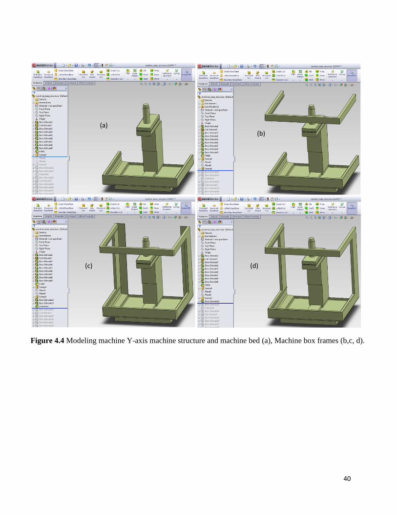
carried out using extrude sketch tool. Figure 4.4 shows modeling the Y-axis machine structure , machine
bed (using sweep tool, Figure 4.4a) and machine box frames using extrude tool (see Figure 4.4(b ,c, and
d)). Machine base modeling (Figure 4.5a, b) and its controller cabinet (Figure 4.5c, d) is shown in Figure
4.5, where also extrude tool is used in current case.
Fig 4.2 General layout for 3D assembly model for CNC Vertical milling machine, explode view.
Fixed Glass
Guard
Slide Glass
Guard
X-axis slide
assembly
Y-axis slide
assembly
Z-axis slide
and spindle
assembly
Machine
structure
assembly

39
Figure 4.3 modeling Z-axis machine structure (a, c, d) and Z-axis slide motor(b)
(a) (b)
(c) (d)
40
Figure 4.4 Modeling machine Y-axis machine structure and machine bed (a), Machine box frames (b,c, d).
(a) (b)
(c) (d)

41
Figure 4.5 Modeling machine structure base (a, b), controller cabinet (c)and Y-axis to base(d).
(a) (b)
(c)
(d)

42
4.2 Modeling machine slides and its assembly
Figure 4.6 shows the X and Y axes slide (a, b, c) and its assembly(d). The Z-axis modeling and
assembly are shown in Figure 4.7. Where spindle and tool holding system also included. It is
worth noting, that standard Mate tool were used during slide and machine structure assembly
system.
Figure 4.6 Modeling machine slides (X and Y) and its sub-assembly.
(a) (b)
(c)
(d)

43
Figure 4.7 Modeling machine Y-axis machine structure and machine bed (a), Machine box frames (b, c,
d).
(a) (b)
(c) (d)

44
4.3 CNC vertical machine assembly modeling
In current stage, machine structure and machine axis sub-assembly were complained together
with machine glass guards to model complete CNC machine 3D as illustrated in Figure 4.8 to
4.10. The following tools in modeling process, Insert components, Mate tools to set the axis
movement directions which cover (standard Mate, Width Mates, Fixed distance mates, adjustable
distance mates).
Figure 4.8 Modeling machine assembly with its sildes (X, Y and Z) as well as machine
glass guards .
(b)
(c) (d)

45
Chapter 5: 3D solid assembly modeling for Manipulator
In this chapter, details 3D modeling will be provided for the manipulator. The final manipulator
assembly will be look like Figure 5.1, exploded drawing is shown in Figure 5.2.
It is worth noting that this type of manipulator usually assembled to suit specific engineering
material handling applications. This type of manipulator powered by double acting pneumatic
cylinders through a set of directional solenoid valves. The cost of this type of manipulator is
quite low compare to traditional industrial manipulator (robot) powered by electric servomotors.
The controller of this type of pneumatic manipulator is based on PLC discrete control system. In
another hand, the electric servomotor manipulator controller based on PC type computer, which
is more expensive controller system compare to PLC control system.
The proposed pneumatic manipulator has two similar slides labeled as A and B mounted at two
different orientations to suit current application, see Figure 5.1. Furthermore, the lower slide
(labeled as D ) is mounted on welded steel bracket (with steel angle profile), see Figure 5.1 and
5.2. The bracket will carry out the manipulator and also will be part of the CNC milling machine
external structure. The final dimension and also its mounting lengths will be determined later
after modeling the overall assembly of the proposed integrated automation system.
The manipulator end-effect (labeled E) has two gripper jaw having one coupler displacement to
hold the workpiece, see Figure 5.1 and also shown clearly in explode drawing Figure 5.2. All
manipulator slides having linear displacements except actuator C has angular displacement see
Figure 5.1. For simplicity it is decided to consider parametric presime workpiece having
dimesnion of 90(H)mm x 58(W)mm x 100mm(D).
The main specifications of pnumatic manipulator are shown in Table 5.1 and given below:

46
Table 4.1 Manipulator main specification
Degree of Freedom (Manipulator Axis), see
Figure 4.1
Part No (Manipulator
axis), see Figure 4.2 Displacement Range
A 1-1 542mm (Linear)
B 1-2 542mm (Linear)
C 1-4 0°-90° (Angler)
D 1-3 243mm (Linear)
E 1-5 90-130mm (Linear)
B B
Figure 5.1 Modeling manipulator assembly with its slides (A, B,C,D and E)
A
E
D
B
C

47
5.1 Modeling manipulator slide D
Initially the main parts of the slide is modeled then assembled to model a complete slide
assembly. After that Mate tool will be used to assign the slide displacement (minimum and
maximum displacement distance).
Figure 5.3, shows the steps utilized to model the slide (D) . Figure 5.3a, shows the slide stopper
bracket, while Figure 5.3c shows the slide units. The two slide guides are modeled in Figure
5.3b, while the complete slide assembly is shown in Figure 5.3d.
Figure 5.2 Explode drawing manipulator assembly
1-1
1-2
1-3
1-5
1-4

48
Standard axis Mates were used to model the assembly of the two rod guides with its slide
bearing. Similar modeling processes are carried out for both slide A and B, see Figure 5.4a to
5.4h.
Figure 5.3Modeling manipulator assembly with its slide (D)
(a) (b)
(c) (d)

49
Figure 5.4 Modeling manipulator slide (A).
(a) (b)
(e)
(c) (d)
(f)
(g) (h)

50
5.2 Modeling the angular displacement (C)
The actual angular displacement of pneumatic actuator (C) have adjustable angular displacement
range up to 270 degrees. In current case, it was decided to set the angular displacement for just
90 degrees, this also applied for current virtual 3D model.
The main mechanical structure of the pneumatic actuator (C) is two racks, one pinion gear and
one double acting cylinders. This configuration used to develop the proposed angular
displacement for actuator (C). Furthermore, there are two adjustable screws utilized to set up the
range of angular displacement (adjusting the stroke of the double acting cylinder). Figure 5.5
shows simplified 3D drawing for this actuator modeled using successive extruded sketch tool,
see Figure 5.5a to 5.5d. Where the actual dimensions are obtained by reverse engineering
technique for actual actuator.
Figure 5.5 Modeling the actuator having angular displacement (C)
(a) (b)
(c) (d)

51
5.3 Modeling the end-effect gripper (E)
Figure 5.6, shows the steps carried out for modeling the two jaw end-effect gripper for the
pneumatic manipulator. Figure 5.6a, b, c and d shows the main parts of the gripper, while Figure
5.6e shows the complete assembly model for all gripper assembly. Extruded sketch tool is used
in modeling the gripper main parts, while Mate tools used to assemble the gripper parts. Also,
coupler Mate tool is used to model the gripper displacement.
Figure 5.6 Modeling the actuator having angular displacement (C)
(a) (b)
(c) (d)
(e)

52
5.4 Modeling steel welded bracket carrying the manipulator basement
Figure 5.7 shows modeling the welded steel structure for the manipulator basement. Figure 5.7a
shows the 3D sketch, while 5.7b shows the extruded profile along the 3D sketch. The welded
steel basement has lower support frame structure to increase the rigidity of the manipulator
basement structure.
Figure 5.7 Modeling manipulator welded steel bracket with angle profile
35x35x5mm
(a)
(b)

53
Chapter 6: 3D solid assembly modeling for integrated automation system
structure
In this chapter a complete modeling for all the integrated automation system between CNC
vertical milling machine and pneumatic manipulator is given and demonstrated. The complete
integrated machine structure will be look like what shown in Figure 6.1.
Figure 6.1 Modeling manipulator welded steel bracket with angle profile 35x35x5mm
Home manipulator
position (parking position)
Home position CNC milling machine
(glass doors closed and machine at
reference positions)
(a)
(b)
Home manipulator
position (parking position)
Home position CNC milling machine
(glass doors open and machine at
reference positions)

54
6.1 Manipulator Machine Sequence
Figure 6.1(a) shows the CNC milling machine at home or reference position. Similarly Figure
6.1b shows the manipulator at home position. At this state, the automatic cycle is enabled. When
the automatic cycle started, the first step will be opening CNC machine glass slide doors and
followed the complete sequencing control system for manipulator and workpiece pneumatic
power clamping fixture that mounted on CNC milling machine bed.
Before, illustrating the manipulator movement sequence, it is important to label the manipulator
actuator movements and given in Table 6.1.
Label Actuator NameMovement
labelFunctions
A+ Moving Up Position
A- Moving Down Position
B+ Arm Forward Position
B-Arm Backward
Position
C+Rotate Arm B counter
clockwise[1]
C-Rotate Arm B
clockwise[1]
D+Movement Toward
CNC m/c
D-Movement Outward
CNC m/c
E+ Open Gripper
E- Close Gripper
F+ Open fixture
F- Close fixture
G+ Door open
G- Door closeG Pneumatic power glass door silde movement
FPneumatic Power Camping Fixture (CNC milling
m/c)
[1] Looking from top view
Table 5.1 Manipolator Actuoator Lable And Functions
D Manipolator Horizental Slide
E End-effect Manipolator Gripper
Manipolator Vertical ArmA
B Manipolator Horizental Arm
C Manipolator Angular Rotation

55
The sequencing movements of the proposed manipulator given as follows:
START, G+, D+, B+, E-, F+, B-,C+,B+, E+, B-, D-, B+, E-, B-, C-, D+, B+, F-, E+, B-,D-,G-
A detail of machine sequence is illustrated as follows:
START, Door open, Movement Toward CNC m/c, Arm Forward Position, Close Gripper, Open
fixture, Arm Backward Position, Rotate Arm B counter clockwise, Arm Forward Position, Open
Gripper, Arm Backward Position, Movement Outward CNC m/c, Arm Forward Position, Close
Gripper, Arm Backward Position, Rotate Arm B clockwise, Movement Toward CNC m/c, Arm
Forward Position, Close fixture, Open Gripper, Arm Backward Position, Movement Outward
CNC m/c, Door close
The machine control sequences with its symbolic addresses are shown below:
Next, we will provide details including Figures illustrating the above machine sequence. Table
6.2 shows summery for illustrated the state of the integrated automation manufacture cell using
3D assembly modeling.
START
, Door open, Movement toward CNC m/c,
Arm Forward Position, Close Gripper,
Open fixture, Arm Backward Position,
Rotate Arm B counter clockwise, Arm Forward Position,
Open Gripper, Arm Backward Position,
Movement Outward CNC m/c, Arm Forward Position,
Close Gripper, Arm Backward Position,
Rotate Arm B clockwise, Movement Toward CNC m/c,
Arm Forward Position, Close fixture,
Open Gripper, Arm Backward Position,
Movement Outward CNC m/c, Door close
START,
G+, D+,
B+, E-,
F+, B-,
C+,B+,
E+, B-,
D-, B+,
E-, B-,
C-, D+,
B+, F-,
E+, B-,
D-,G-

56
Machine Task No. Machine cell fanction lable Figure No
1 G+ 5.1b
2 D+ 5.2a
3 B+ 5.2b
4 E- 5.3a
5 F+ 5.3b
6 B- 5.4a
7 C+ 5.4b
8 B+ 5.5a
9 E+ 5.5b
10 B- 5.6a
11 D- 5.6b
12 B+ 5.7a
13 E- 5.7b
14 B- 5.8a
15 C- 5.8b
16 D+ 5.9a
17 B+ 5.9b
18 F- 5.10a
19 E+ 5.10b
20 B- 5.11a
21 D- 5.11b
22 G- 5.12
Table 5.2 List of machine cell function figures

57
Figure 6.2 (a) Slide D+ Moving toward CNC m/c, (b) Arm B+ forward position
(a)
(b)

58
Figure 6.3 (a) Gripper E- close gripper, (b) Fixture F+ open fixture
(a)
(b)

59
Figure 6.4(a) Arm B- backward position, (b) Arm B rotation C+ counter clockwise
(a)
(b)

60
Figure 6.5(a) Arm B+ forward position, (b) Gripper E+ open gripper
(a)
(b)

61
Figure 6.6(a) Arm B- backward position, (b) Slide D- Moving outward CNC m/c
(a)
(b)

62
Figure 6.7(a) Arm B+ forward position, (b) Gripper E- close gripper
(a)
(b)

63
Figure 6.8(a) Arm B- backward position, (b) Arm B rotation C- clockwise
(a)
(b)

64
Figure 6.9 (a) Slide D+ Moving toward CNC m/c, (b) Arm B+ forward position
(a)
(b)

65
Figure 6.10 (a) Fixture F- close fixture, (b) Gripper E+ open gripper
(a)
(b)

66
Figure 6.11(a) Arm B- backward position, (b) Slide D- Moving outward CNC m/c
(a)
(b)
67
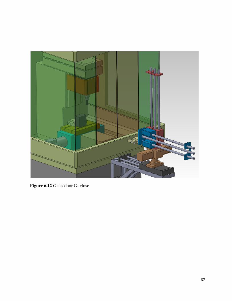
Figure 6.11 Glass door G- close

68
6.2 Relay Ladder Logic program for given machine sequence
Hear we will write the Relay Ladder Logic Program for machine sequence and mainly the
pneumatic manipulator. The machine sequence will be enabled or started by getting M-code
from CNC controller and also, will get discrete signal from PLC controller indicating the
manipulator finished and in its parking position.
The machine sequence is grouped to eight groups according to CASCADE method [3,4] as
shown below table:
The Relay Ladder Relay program will be design for above machine sequence, where the Relay
Ladder will be divided to two modules. The flip-flop module and output module. The flip-flop
modules cover eight flip-flops for the eight assigned groups. While, the output module cover 14
discrete outputs for 7 double acting cylinders and 7 solenoid valves. All the solenoid valves have
non-sustain discrete signals (e.g. all have mechanical memory). Furthermore, all the double
acting cylinders haves two reed proximity switches at the two extreme positions for feedback
control system.
For example, cylinder B has two solenoid valves labeled as B+ and B- including two reed
switches labeled b+ and b- located at the two extreme positions. The plus sign indicates the
actuator at the forward positions while the negative sign indicating the backward positions.
START,
Machine cycle Group #
G+, D+,B+, E-, F+, Group #1
B-,C+, Group #2
B+,E+, Group #3
B-,D-, Group #4
B+,E-, Group #5
B-,C-, D+, Group #6
B+, F-,E+, Group #7
B-, D-,G- Group #8

69
The relay ladder logic program is shown in Figure 2.13 to 2.15. Figure 2.13 shows the flip-flop
module for the Relay Ladder, while Figure 2.14 and 2.15 show the Relay Ladder logic the output
module.

70
Figure 6.13

71
Figure 6.14

72
Figure 6.11

73
6.3 Summery and Conclusion
Integrated automatic system between vertical CNC machine and discrete pneumatic
manipulator was selected for current case study.
The two sub-systems mainly the vertical CNC milling machine and pneumatic manipulators
are both available in Industrial Engineering Department laboratory. Where reverse
engineering procedure is used to obtain its dimensions to be used in 3D modeling through
CAD software available in College of Engineering computer laboratory.
It was decided to use CAD system to model and verify the operations of the integrated
automatic manufacturing cell. Where steel welded structure also included in the model to
establish the integration between two sub-systems.
Finally, the machine sequence for the pneumatic manipulator was identified and tested
virtually using the 3D CAD model developed in current project.
Pneumatic power clamping system is also considered on the proposed integrated automatic
manufacturing cell.
The final mounting dimensions that represent the main integration between CNC milling
machine, manipulator, steel welded basement and power clamping system are identified to be
used later for actual cell production.
For simplicity it was decided to model cubic shape workpiece, and two jaw with coupler
movements is considered for pneumatic power clamping fixture.
Finally, the Relay Ladder Logic program for controlling the manipulator operation sequence
is written for Simians Simatic S7-300 PLC.

74
References:
[1] Al Asker, H. A., Al Askar R. A., Al Homayin A. A., CNC retrofitting vertical milling
machine, BSc, project KSU, Industrial Engineering Department, 2nd semester 2012.
[2] Mach3 Ver 3.x, Macro Programmers Reference Manual, Aug 22nd
, 2010 Ver 3.43.19.
USA.
[3] David W. Pessen, Industrial Automation, Circuit Design & Components, A Wily-
Interscience Publication, John Wily & Sons, 1989.
[4] Manufacturing Automation Using PLC, Ali M Alsamhan, Saied M Darwish, Grant
16/424 of Research center College of Engineering, King Saud University, 2004.
[5] Laboratory Manual Version 1.00, (IE437,Indusrial Engineering Department, KSU)
Oct,10,2009