intel omni-path fabric switches€” intel® omni-path fabric switches command line interface...
TRANSCRIPT

Intel® Omni-Path Fabric SwitchesGUI User Guide
November 2015
Order No.: H76457-1.0

You may not use or facilitate the use of this document in connection with any infringement or other legal analysis concerning Intel products describedherein. You agree to grant Intel a non-exclusive, royalty-free license to any patent claim thereafter drafted which includes subject matter disclosedherein.
No license (express or implied, by estoppel or otherwise) to any intellectual property rights is granted by this document.
All information provided here is subject to change without notice. Contact your Intel representative to obtain the latest Intel product specifications androadmaps.
The products described may contain design defects or errors known as errata which may cause the product to deviate from published specifications.Current characterized errata are available on request.
Copies of documents which have an order number and are referenced in this document may be obtained by calling 1-800-548-4725 or visit http://www.intel.com/design/literature.htm.
Intel technologies’ features and benefits depend on system configuration and may require enabled hardware, software or service activation. Learnmore at http://www.intel.com/ or from the OEM or retailer.
No computer system can be absolutely secure.
Intel, the Intel logo, Intel Xeon Phi, and Xeon are trademarks of Intel Corporation in the U.S. and/or other countries.
*Other names and brands may be claimed as the property of others.
Copyright © 2015, Intel Corporation. All rights reserved.
Intel® Omni-Path Fabric SwitchesGUI User Guide November 20152 Order No.: H76457-1.0
Revision History
Date Revision Description
November 2015 1.0 Document has been updated for Revision 1.0.
September 2015 0.7 Document has been updated for Revision 0.7.
April 2015 0.5 Initial release of document.
Revision History—Intel® Omni-Path Fabric
Intel® Omni-Path Fabric SwitchesNovember 2015 GUI User GuideOrder No.: H76457-1.0 3

Contents
Revision History..................................................................................................................3
Preface............................................................................................................................... 8Intended Audience....................................................................................................... 8Documentation Set.......................................................................................................8Documentation Conventions.......................................................................................... 9Laser Safety Information...............................................................................................9Electrostatic Discharge Sensitivity (ESDS) Precautions.................................................... 10License Agreements....................................................................................................10Technical Support.......................................................................................................10
1.0 Introduction................................................................................................................111.1 Overview............................................................................................................. 111.2 Accessing Chassis Viewer.......................................................................................111.3 Home Page.......................................................................................................... 121.4 Component Details Area........................................................................................ 13
1.4.1 Details Header..........................................................................................141.4.2 Chassis View Component Information Area...................................................141.4.3 Modifying Switch Component Information.....................................................151.4.4 Rebooting Switches...................................................................................151.4.5 Chassis View Component Information Area Tabs........................................... 16
2.0 Configuration and Monitoring..................................................................................... 192.1 Chassis View Menu................................................................................................192.2 Logging............................................................................................................... 19
2.2.1 Viewing the Log........................................................................................202.2.2 Set Level................................................................................................. 212.2.3 Reset Log Levels.......................................................................................252.2.4 Purging the Log........................................................................................ 26
2.3 Maintenance.........................................................................................................272.3.1 Select Boot Image.................................................................................... 272.3.2 Firmware Update...................................................................................... 282.3.3 LDAP Configuration................................................................................... 302.3.4 HTTP/CLI Session Configuration.................................................................. 312.3.5 Subnet Manager Configuration File.............................................................. 332.3.6 Post Diagnostics....................................................................................... 33
2.4 SNMP..................................................................................................................342.4.1 Target Configuration................................................................................. 352.4.2 Filter Status............................................................................................. 382.4.3 Set Community Strings..............................................................................39
2.5 Configuration File Administration.............................................................................402.5.1 Administer............................................................................................... 402.5.2 Host Upload/Download.............................................................................. 422.5.3 Trap Control.............................................................................................432.5.4 Subnet Manager Configuration File.............................................................. 45
2.6 Chassis Traps.......................................................................................................462.7 Port Statistics.......................................................................................................48
2.7.1 View Port Statistics................................................................................... 49
Intel® Omni-Path Fabric—Contents
Intel® Omni-Path Fabric SwitchesGUI User Guide November 20154 Order No.: H76457-1.0

2.7.2 Understanding Port Naming Conventions......................................................492.7.3 Port Statistics Field Descriptions..................................................................492.7.4 Port Beacon............................................................................................. 51
2.8 Time Service........................................................................................................ 522.8.1 Setting System Time................................................................................. 522.8.2 Using Network Time Protocol (NTP)............................................................. 532.8.3 Manually Setting System Time....................................................................542.8.4 Setting Time Zone and Daylight Saving Time (DST).......................................55
2.9 OOB LAN IP Menu................................................................................................. 562.9.1 Configuring the Switch OOB IP Address........................................................562.9.2 Configuring the Switch Default Gateway IP Address.......................................57
2.10 Subnet Manager Control.......................................................................................582.10.1 Accessing the Subnet Manager Control Window........................................... 582.10.2 Starting the Fabric Manager......................................................................592.10.3 Restarting the Fabric Manager...................................................................592.10.4 Stopping the Fabric Manager.................................................................... 602.10.5 Automatically starting the Intel® Omni-Path Fabric Suite Fabric Manager........ 60
Contents—Intel® Omni-Path Fabric
Intel® Omni-Path Fabric SwitchesNovember 2015 GUI User GuideOrder No.: H76457-1.0 5

Figures1 Intel® OP Edge Switch 100 Family Home Page.............................................................132 Component Details Area for Intel® OP Edge Switch 100 Family...................................... 143 Details Header........................................................................................................ 144 Chassis View Component Information Area................................................................. 155 Chassis View Component Information Area, Showing LEDs and Sensors Tab....................166 Logging Submenu....................................................................................................207 Maintenance Menu...................................................................................................278 SNMP Submenu.......................................................................................................359 Configuration File Administration Menu.......................................................................4010 Chassis Traps Menu................................................................................................. 4611 Port Stats Menu.......................................................................................................4812 Time Service Menu.................................................................................................. 5213 OOB LAN IP Menu....................................................................................................5614 Subnet Manager Control Button.................................................................................58
Intel® Omni-Path Fabric—Figures
Intel® Omni-Path Fabric SwitchesGUI User Guide November 20156 Order No.: H76457-1.0

Tables1 Chassis View Tabs and Descriptions........................................................................... 172 Chassis View Menu Options.......................................................................................193 SNMP Target Configuration Fields.............................................................................. 374 Configuration File Traps............................................................................................445 Chassis Traps..........................................................................................................476 Port Statistics Fields and Descriptions.........................................................................49
Tables—Intel® Omni-Path Fabric
Intel® Omni-Path Fabric SwitchesNovember 2015 GUI User GuideOrder No.: H76457-1.0 7

Preface
This manual is part of the documentation set for the Intel® Omni-Path Fabric (Intel®OP Fabric), which is an end-to-end solution consisting of adapters, edge switches,director switches and fabric management and development tools.
The Intel® OP Fabric delivers a platform for the next generation of High-PerformanceComputing (HPC) systems that is designed to cost-effectively meet the scale, density,and reliability requirements of large-scale HPC clusters.
Both the Intel® OP Fabric and standard InfiniBand* are able to send Internet Protocol(IP) traffic over the fabric, or IPoFabric. In this document, however, it is referred to asIP over IB or IPoIB. From a software point of view, IPoFabric and IPoIB behave thesame way and, in fact, use the same ib_ipoib driver to send IP traffic over the ib0and/or ib1 ports.
Intended Audience
The intended audience for the Intel® Omni-Path (Intel® OP) document set is networkadministrators and other qualified personnel.
Documentation Set
The following are the list of the complete end-user publications set for the Intel®Omni-Path product. These documents can be downloaded from https://downloadcenter.intel.com/.
• Hardware Documents:
— Intel® Omni-Path Fabric Switches Hardware Installation Guide
— Intel® Omni-Path Fabric Switches GUI User Guide
— Intel® Omni-Path Fabric Switches Command Line Interface Reference Guide
— Intel® Omni-Path Edge Switch Platform Configuration Reference Guide
— Intel® Omni-Path Fabric Managed Switches Release Notes
— Intel® Omni-Path Fabric Externally-Managed Switches Release Notes
— Intel® Omni-Path Host Fabric Interface Installation Guide
— Intel® Omni-Path Host Fabric Interface Release Notes
• Software Documents:
— Intel® Omni-Path Fabric Software Installation Guide
— Intel® Omni-Path Fabric Suite Fabric Manager User Guide
— Intel® Omni-Path Fabric Suite FastFabric User Guide
— Intel® Omni-Path Fabric Host Software User Guide
— Intel® Omni-Path Fabric Suite Fabric Manager GUI Online Help
Intel® Omni-Path Fabric—Preface
Intel® Omni-Path Fabric SwitchesGUI User Guide November 20158 Order No.: H76457-1.0

— Intel® Omni-Path Fabric Suite Fabric Manager GUI User Guide
— Intel® Omni-Path Fabric Suite FastFabric Command Line Interface ReferenceGuide
— Intel® Performance Scaled Messaging 2 (PSM2) Programmer's Guide
— Intel® Omni-Path Fabric Performance Tuning User Guide
— Intel® Omni-Path Host Fabric Interface Platform Configuration ReferenceGuide
— Intel® Omni-Path Fabric Software Release Notes
— Intel® Omni-Path Fabric Manager GUI Release Notes
Documentation Conventions
This guide uses the following documentation conventions:
• Note: provides additional information.
• Caution: indicates the presence of a hazard that has the potential of causingdamage to data or equipment.
• Warning: indicates the presence of a hazard that has the potential of causingpersonal injury.
• Text in blue font indicates a hyperlink (jump) to a figure, table, or section in thisguide. Links to Web sites are also shown in blue. For example:
See License Agreements on page 10 for more information.
For more information, visit www.intel.com.
• Text in bold font indicates user interface elements such as a menu items, buttons,check boxes, or column headings. For example:
Click the Start button, point to Programs, point to Accessories, and then clickCommand Prompt.
• Text in Courier font indicates a file name, directory path, or command line text.For example:
Enter the following command: sh ./install.bin• Key names and key strokes are shown in underlined bold uppercase letters. For
example:
Press CTRL+P and then press the UP ARROW key.
• Text in italics indicates terms, emphasis, variables, or document titles. Forexample:
For a complete listing of license agreements, refer to the Intel® Software End UserLicense Agreement.
Laser Safety Information
This product may use Class 1 laser optical transceivers to communicate over the fiberoptic conductors. The U.S. Department of Health and Human Services (DHHS) doesnot consider Class 1 lasers to be hazardous. The International ElectrotechnicalCommission (IEC) 825 Laser Safety Standard requires labeling in English, German,Finnish, and French stating that the product uses Class 1 lasers. Because it isimpractical to label the transceivers, the following label is provided in this manual.
Preface—Intel® Omni-Path Fabric
Intel® Omni-Path Fabric SwitchesNovember 2015 GUI User GuideOrder No.: H76457-1.0 9

Electrostatic Discharge Sensitivity (ESDS) Precautions
The assemblies used in the switch chassis are ESD sensitive. Observe ESD handlingprocedures when handling any assembly used in the switch chassis.
License Agreements
This software is provided under one or more license agreements. Please refer to thelicense agreement(s) provided with the software for specific detail. Do not install oruse the software until you have carefully read and agree to the terms and conditionsof the license agreement(s). By loading or using the software, you agree to the termsof the license agreement(s). If you do not wish to so agree, do not install or use thesoftware.
Technical Support
Technical support for Intel® Omni-Path products is available 24 hours a day, 365 daysa year. Please contact Intel Customer Support or visit www.intel.com for additionaldetail.
Intel® Omni-Path Fabric—Preface
Intel® Omni-Path Fabric SwitchesGUI User Guide November 201510 Order No.: H76457-1.0

1.0 Introduction
This manual describes the Intel® Omni-Path Fabric Chassis Viewer graphical userinterface (GUI), which enables configuration and administration of the Intel® Omni-Path Switch family.
This manual is organized as follows:
• This section provides an overview of the GUI, including accessing Chassis Viewer,displaying the home page, and a tour of different system views.
• Configuration and Monitoring on page 19 describes the configuration andadministration tasks.
Overview
The Intel® Omni-Path Fabric Chassis Viewer is browser-based device managementsoftware. Chassis Viewer provides the primary management interface for the Intel®Omni-Path Switch family, allowing you to perform management, configuration, andmonitoring tasks.
The Chassis Viewer runs on the firmware of the Intel® Omni-Path Switch family. Thebrowser must be on a workstation that has IP connectivity to the LAN port (RJ-45connector) on the switch.
Chassis Viewer manages:
• The switch chassis
• Logging and monitoring functionality
Accessing Chassis Viewer
1. To access Chassis Viewer, point a browser to the IP address of the switch.
Note: The default IP address is 192.168.100.9 and the default netmask is255.255.255.0.
2. If user authentication is enabled, a User Authentication window is displayed.
1.1
1.2
Introduction—Intel® Omni-Path Fabric
Intel® Omni-Path Fabric SwitchesNovember 2015 GUI User GuideOrder No.: H76457-1.0 11

Enter the user name and password. Default values are:
• User name: admin• Password: adminpassThe Chassis Viewer home page is displayed.
Home Page
The Chassis Viewer home page provides a high-level overview of the switch. This areais the starting point for more detailed information for the chassis and components(fans and power supplies), leaf modules, spine modules, and management modules.The selected component provides hyperlinks to related menus and information whereyou can perform configuration and monitoring tasks.
1.3
Intel® Omni-Path Fabric—Introduction
Intel® Omni-Path Fabric SwitchesGUI User Guide November 201512 Order No.: H76457-1.0

Figure 1. Intel® OP Edge Switch 100 Family Home Page
The ? (HELP) button displays online help. Each help window provides a high-level,topic-specific description.
Component Details Area
The Component Details Area has three major sections:
• Details Header
• Information area
• Menu
1.4
Introduction—Intel® Omni-Path Fabric
Intel® Omni-Path Fabric SwitchesNovember 2015 GUI User GuideOrder No.: H76457-1.0 13

Figure 2. Component Details Area for Intel® OP Edge Switch 100 Family
Details Header
The Details Header allows you to execute command tasks for each hardwarecomponent.
Figure 3. Details Header
The Details Header contains the following buttons:
• Logout
Note: The Logout button is only displayed if you have set the User Authenticationparameter to Login Enabled through the HTTP Session Configurationsubmenu. For more information, see HTTP/CLI Session Configuration onpage 31.
• Reboot
• View FRU [View Field Replaceable Unit (FRU) Information]
• View Log
• Home (Intel® OP Director Switch 100 Family only)
• ? / Help
Chassis View Component Information Area
The Chassis View Component Information Area allows you to monitor importantinformation for each specific hardware component, as well as important systeminformation. The information area is comprised of two different fields:
• White fields allow you to add or modify applicable general and system informationthat is specific to your environment.
• Gray fields are tied to live data from the selected hardware component as well aslive system information.
1.4.1
1.4.2
Intel® Omni-Path Fabric—Introduction
Intel® Omni-Path Fabric SwitchesGUI User Guide November 201514 Order No.: H76457-1.0

Figure 4. Chassis View Component Information Area
Modifying Switch Component Information
Use the following procedure to modify the fields for switch components:
1. Select the applicable tab: LED and Sensors, System, Chassis FRU, Power,Fan, or Backplane.
2. Click on the row to be modified.
3. In the text boxes, enter information for your network environment.
4. To save, click the Apply button at the bottom of the window.
Rebooting Switches
Rebooting the Intel® OP Edge Switch 100 Family
1. From the Chassis Details Header, click Reboot.
2. A confirmation window is displayed. Click OK to reboot.
The following rebooting status window is displayed.
1.4.3
1.4.4
Introduction—Intel® Omni-Path Fabric
Intel® Omni-Path Fabric SwitchesNovember 2015 GUI User GuideOrder No.: H76457-1.0 15

Chassis View Component Information Area Tabs
The tabs along the top of the information area present information about the followingcomponents:
• LED and sensor information
• Overall system information
• Switch Field Replaceable Unit (FRU) Information
• Power supply information
• Fan information
• Switch backplane information
Table 1 on page 17 provides details on all the tabs in the Chassis View ComponentInformation Area.
Figure 5. Chassis View Component Information Area, Showing LEDs and Sensors Tab
1.4.5
Intel® Omni-Path Fabric—Introduction
Intel® Omni-Path Fabric SwitchesGUI User Guide November 201516 Order No.: H76457-1.0

Table 1. Chassis View Tabs and Descriptions
Tab/Information Description
LEDs and Sensors Tab
Chassis Units Test Displays switch component LED information for chassis status, fan, and powersupplies.Note: For a detailed explanation of physical LEDs on the hardware
components, refer to the Intel® Omni-Path Fabric Switches HardwareInstallation Guide.
Chassis Sensor Data Slot-based temperature and AC-power sensor data for the internal switchingcomplex.
System Tab The System tab displays overall system information for the applicable switchchassis. This information includes the following items:
Out of Band LAN IP The IP address of the switch. The IP address of the switch can be changed bythe administrator.
Net Mask The current net mask settings for the Chassis. The net mask of the chassiscan be changed by the administrator.
System Description A read-only textual description of the system.
IB Node Description Assigned by the administrator, the node description is a fabric-applicablename that will be displayed within the Intel® Omni-Path Fabric ChassisViewer. To reset this field to the default setting, click the Field Defaultbutton.Note: If this field has been changed since the last reboot of either
management module, the next reboot will be treated as disruptive.
System Uptime The elapsed time since the master management module was re-initialized.
System Contact The textual identification of the contact person and their contact informationfor this system, assigned by the administrator.
System Name The name for the system, assigned by an administrator. One convention is touse the system's fully qualified domain name.
System Location The location of the system, assigned by an administrator.
Apply Button Saves any changes to memory.
Refresh Button Refreshes all fields in the System tab.
Chassis FRU Tab The Chassis FRU tab displays switch Field Replaceable Unit (FRU)information. This information includes the following items:
Type The type of component.
Description A description of the component, assigned by an administrator.
Alias Name Name of the component, assigned by an administrator.
Serial Num Component serial number
Detail A button for each row that displays additional detail about the component.Additional details include: Part Number, Model, Version, Manufacturer Name,Product Name, Manufacturer Identification, and Manufactured Date (ifavailable).
Apply Button Saves any changes to memory.
Refresh Button Refreshes all fields in the Chassis FRU tab.
Power Tab The Power tab displays switch power supply information. This informationincludes the following items:
Description A description of the component, assigned by an administrator.
continued...
Introduction—Intel® Omni-Path Fabric
Intel® Omni-Path Fabric SwitchesNovember 2015 GUI User GuideOrder No.: H76457-1.0 17
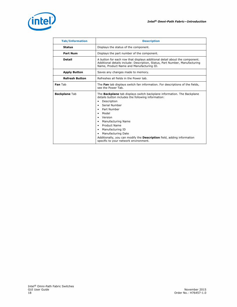
Tab/Information Description
Status Displays the status of the component.
Part Num Displays the part number of the component.
Detail A button for each row that displays additional detail about the component.Additional details include: Description, Status, Part Number, ManufacturingName, Product Name and Manufacturing ID.
Apply Button Saves any changes made to memory.
Refresh Button Refreshes all fields in the Power tab.
Fan Tab The Fan tab displays switch fan information. For descriptions of the fields,see the Power Tab.
Backplane Tab The Backplane tab displays switch backplane information. The Backplanedetails button includes the following information:• Description• Serial Number• Part Number• Model• Version• Manufacturing Name• Product Name• Manufacturing ID• Manufacturing DateAdditionally, you can modify the Description field, adding informationspecific to your network environment.
Intel® Omni-Path Fabric—Introduction
Intel® Omni-Path Fabric SwitchesGUI User Guide November 201518 Order No.: H76457-1.0
2.0 Configuration and Monitoring
This section provides detailed, task-oriented descriptions for using the Chassis Viewerfor configuration and monitoring.
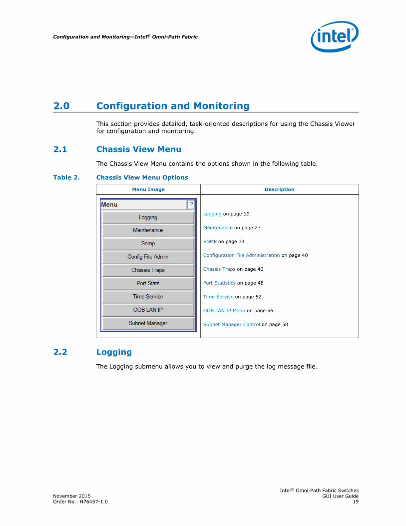
Chassis View Menu
The Chassis View Menu contains the options shown in the following table.
Table 2. Chassis View Menu Options
Menu Image Description
Logging on page 19 Maintenance on page 27 SNMP on page 34 Configuration File Administration on page 40 Chassis Traps on page 46 Port Statistics on page 48 Time Service on page 52 OOB LAN IP Menu on page 56 Subnet Manager Control on page 58
Logging
The Logging submenu allows you to view and purge the log message file.
2.1
2.2
Configuration and Monitoring—Intel® Omni-Path Fabric
Intel® Omni-Path Fabric SwitchesNovember 2015 GUI User GuideOrder No.: H76457-1.0 19

Figure 6. Logging Submenu
Viewing the Log
Each management module maintains a separate log. The View Log button allows youto view the message log.
To view the message log:
1. From the menu, select Logging.
The View Log button is displayed.
2. Click View Log.
The Log Message window is displayed.
2.2.1
Intel® Omni-Path Fabric—Configuration and Monitoring
Intel® Omni-Path Fabric SwitchesGUI User Guide November 201520 Order No.: H76457-1.0

To save a log message for further analysis, perform the following steps:
1. From the Log Messages window, select Edit, Select All (or CTRL + A).
2. Select Edit, Copy (or CTRL + C).
3. Open a text editing package, such as Notepad.
4. Select Edit, Paste (or CTRL + V).
5. Save as a plain text (.txt) file.
Set Level
To efficiently set up log filtering, enable only those levels that need to appear in thelog. The levels are handled by two layers:
• Preset Layer. This layer allows you to select the levels of messages the switch willgenerate. If the level is selected here, it could be logged into Ram Device or theSyslog Device. Any unselected levels will not be logged to any device.
• Device Levels. This allows you to select the levels of log messages to be saved.
Note: To save log message levels, select the log level in the Device tab and Preset tab.
The Set Level button allows you to set log level configuration parameters for allsoftware modules.
To set log levels:
1. From the menu, select Logging.
The Set Level button is displayed.
2. Click Set Level.
3. The Log System Configurator window (Device tab) is displayed.
2.2.2
Configuration and Monitoring—Intel® Omni-Path Fabric
Intel® Omni-Path Fabric SwitchesNovember 2015 GUI User GuideOrder No.: H76457-1.0 21

Device Tab
The Device tab presents current log level configuration settings for the followingsoftware modules:
• RAM – The circular log buffer contained in memory. To access the contents of thisbuffer, use the Chassis Viewer View Log button.
• Syslog – Messages that are sent to the syslog host specified on the Syslog tab.
From this window, you can change any of the log level settings for a specific softwaremodule by clicking on the Configure button, which displays a configuration window:
To change any Log Level settings:
1. Click the On-Off check box to the right of the setting.
2. Click the Apply button to save any changes.
The following list describes each of the Log Level configuration parameters.
• DUMP – Indicates that a problem has caused the system to produce a systemdump file. Intel recommends that you retrieve the dump that was produced.Support engineers may require the information contained in the dump file todiagnose the cause of the problem.
• FATAL – Indicates that a non-recoverable system problem has occurred. Youshould reboot the system or component and verify that the subsystem is fullyfunctional to determine whether the fault has been corrected. If the problempersists, you should contact the supplier.
2.2.2.1
Intel® Omni-Path Fabric—Configuration and Monitoring
Intel® Omni-Path Fabric SwitchesGUI User Guide November 201522 Order No.: H76457-1.0

• ERROR – Indicates that a serious system error has occurred which might berecoverable. If the system exhibits any instability, you should reboot the systemor component. If errors persist, you should immediately contact the supplier'stechnical support.
• ALARM – Indicates that a serious problem has occurred which degrades capacityor service. If the error is recoverable, you should correct the failure. If the alarm/failure persists, you should reboot the system at a convenient time. If the problemis still not cleared, you should contact the supplier.
• WARNING – Indicates that a recoverable problem has occurred. You do not needto take action.
• PARTIAL – When more information is available, Partial causes additionalmessage-related details to be displayed.
• CONFIGURATION – An informational message indicating changes that a user hasmade to the system configuration. You do not need to take any action.
• INFO – Informational messages that occur during a system or component boot.You do not need to take any action.
• PERIODIC – An informational message containing periodic statistics. You do notneed to take action.
• NOTICE – Notice is used for failures that could be a result of “frequent” useractions, such as a server reboot.
Debug message levels 1 through 5:
Debug messages are for supplier and/or engineering use and are not necessarilyindicative of actions that an end user may need to take.
• DEBUG1 – Messages that describe the states of connections and links.
• DEBUG2 – Messages that describe major configuration changes or operations.
• DEBUG3 – Messages that describe the I/O flow.
• DEBUG4 – Messages that contain the packet dumps within an I/O flow. I/O flowscontain multiple packets.
• DEBUG5 – Messages that contain the packet dumps within an I/O flow. I/O flowscontain multiple packets.
Caution: When configuring the log levels to display debug messages, care should be taken toensure that system performance issues are weighed against troubleshootingrequirements. Generally, the higher the debug number the more information is writtento the log. Specifically, DEBUG3 through DEBUG5 have the most effect on systemperformance.
Preset Tab
The Preset tab allows you to quickly change log level settings for all softwaremodules on the switch.
2.2.2.2
Configuration and Monitoring—Intel® Omni-Path Fabric
Intel® Omni-Path Fabric SwitchesNovember 2015 GUI User GuideOrder No.: H76457-1.0 23

To change the log level settings:
1. Click the On-Off check box to the right of the setting(s).
2. Click the Apply button to save any changes.
Syslog Host Tab
The Syslog Host tab allows you to configure logging messages to be sent to a sysloghost through an IP address or domain name server (DNS) host name.
Note: The switch only saves the in-memory log when it is able to gracefully shutdown andrestore the log from the persistent state when it boots. Power cycling the switch,removing or resetting the management card, or any hardware failure that causes anASYNC reboot does not persistently save the in-memory log. To avoid losing loginformation in the event of a hardware failure, follow the instructions in ConfigureSyslog on the Syslog Server on page 25.
2.2.2.3
Intel® Omni-Path Fabric—Configuration and Monitoring
Intel® Omni-Path Fabric SwitchesGUI User Guide November 201524 Order No.: H76457-1.0
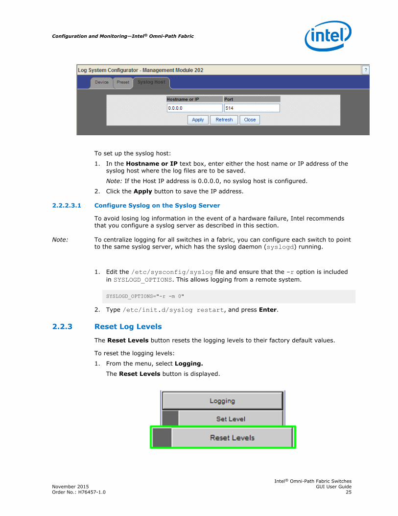
To set up the syslog host:
1. In the Hostname or IP text box, enter either the host name or IP address of thesyslog host where the log files are to be saved.
Note: If the Host IP address is 0.0.0.0, no syslog host is configured.
2. Click the Apply button to save the IP address.
Configure Syslog on the Syslog Server
To avoid losing log information in the event of a hardware failure, Intel recommendsthat you configure a syslog server as described in this section.
Note: To centralize logging for all switches in a fabric, you can configure each switch to pointto the same syslog server, which has the syslog daemon (syslogd) running.
1. Edit the /etc/sysconfig/syslog file and ensure that the -r option is includedin SYSLOGD_OPTIONS. This allows logging from a remote system.
SYSLOGD_OPTIONS="-r -m 0"
2. Type /etc/init.d/syslog restart, and press Enter.
Reset Log Levels
The Reset Levels button resets the logging levels to their factory default values.
To reset the logging levels:
1. From the menu, select Logging.
The Reset Levels button is displayed.
2.2.2.3.1
2.2.3
Configuration and Monitoring—Intel® Omni-Path Fabric
Intel® Omni-Path Fabric SwitchesNovember 2015 GUI User GuideOrder No.: H76457-1.0 25

2. Click Reset Levels.
The Reset Levels window is displayed.
3. To reset the logging levels, click OK.
Purging the Log
The Purge Log button purges the RAM, clearing the log file(s).
To purge the log:
1. From the menu, click Logging.
The Purge Log button is displayed.
2. Click Purge Log.
3. The Purge Log confirmation window is displayed.
4. Click OK.
2.2.4
Intel® Omni-Path Fabric—Configuration and Monitoring
Intel® Omni-Path Fabric SwitchesGUI User Guide November 201526 Order No.: H76457-1.0

5. The message log file is now purged.
Maintenance
The Maintenance menu allows you to select an alternate firmware file for the switch,reboot the switch, set and configure authentications for the switch, and set HTTP andCLI session time out parameters, as well as set security requirements for the switch.
Figure 7. Maintenance Menu
Note: For rebooting information, see Rebooting Switches on page 15.
Select Boot Image
The Select Boot Image button allows you to choose an alternative boot image forthe switch. To select a boot image:
1. From the menu, select Maintenance.
The Select Boot Image button is displayed.
2.3
2.3.1
Configuration and Monitoring—Intel® Omni-Path Fabric
Intel® Omni-Path Fabric SwitchesNovember 2015 GUI User GuideOrder No.: H76457-1.0 27
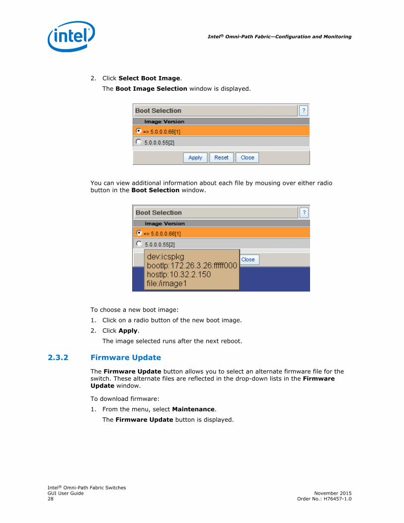
2. Click Select Boot Image.
The Boot Image Selection window is displayed.
You can view additional information about each file by mousing over either radiobutton in the Boot Selection window.
To choose a new boot image:
1. Click on a radio button of the new boot image.
2. Click Apply.
The image selected runs after the next reboot.
Firmware Update
The Firmware Update button allows you to select an alternate firmware file for theswitch. These alternate files are reflected in the drop-down lists in the FirmwareUpdate window.
To download firmware:
1. From the menu, select Maintenance.
The Firmware Update button is displayed.
2.3.2
Intel® Omni-Path Fabric—Configuration and Monitoring
Intel® Omni-Path Fabric SwitchesGUI User Guide November 201528 Order No.: H76457-1.0

2. Click Firmware Update.
The Firmware Update window is displayed.
3. In the Select Target Slot column, select the hardware component to change itsfirmware.
Note: If there are multiple modules of the same type, you can select all slots thatapply.
4. In the Firmware Update Package: text box, use the Browse... button to locatethe path to the alternate firmware file.
Note: Before using the Browse... button, make certain that the browser is tied toan FTP server where the firmware files reside (that is, if the firmware filedoes not reside on the local computer).
5. To have the new image become active after the next reboot, make certain that thebox(es) in the Boot? column are checked.
6. Click the Update Firmware button.
Configuration and Monitoring—Intel® Omni-Path Fabric
Intel® Omni-Path Fabric SwitchesNovember 2015 GUI User GuideOrder No.: H76457-1.0 29

LDAP Configuration
The lightweight directory access protocol (LDAP) configuration feature allows you toset and configure authentication for the switch. The LDAP service resides on a serverthat has access to a usercode and password database.
When a user attempts to login to either the Chassis Viewer GUI or the CLI, the LDAPclient intercepts the login attempt and rather than authenticating internally, encryptsand packages the information in an LDAP packet and sends it to a pre-configuredLDAP server over TCP/IP (i.e., the out-of-band LAN). The LDAP server receives therequest, passes it on to the authentication services, and responds to the client with ayes or no, either allowing or denying the user access.
When LDAP is disabled, internal authentication becomes the default.
To set up LDAP authentication:
1. From the menu, select Maintenance.
The LDAP Configuration button is displayed.
2. Click LDAP Configuration.
The LDAP Authentication window is displayed.
2.3.3
Intel® Omni-Path Fabric—Configuration and Monitoring
Intel® Omni-Path Fabric SwitchesGUI User Guide November 201530 Order No.: H76457-1.0
3. In the LDAP Server IP Address box, enter the address of the applicable LDAPserver.
4. In the LDAP Server Port box, enter the applicable server port number (thedefault is 389).
5. Click Apply.
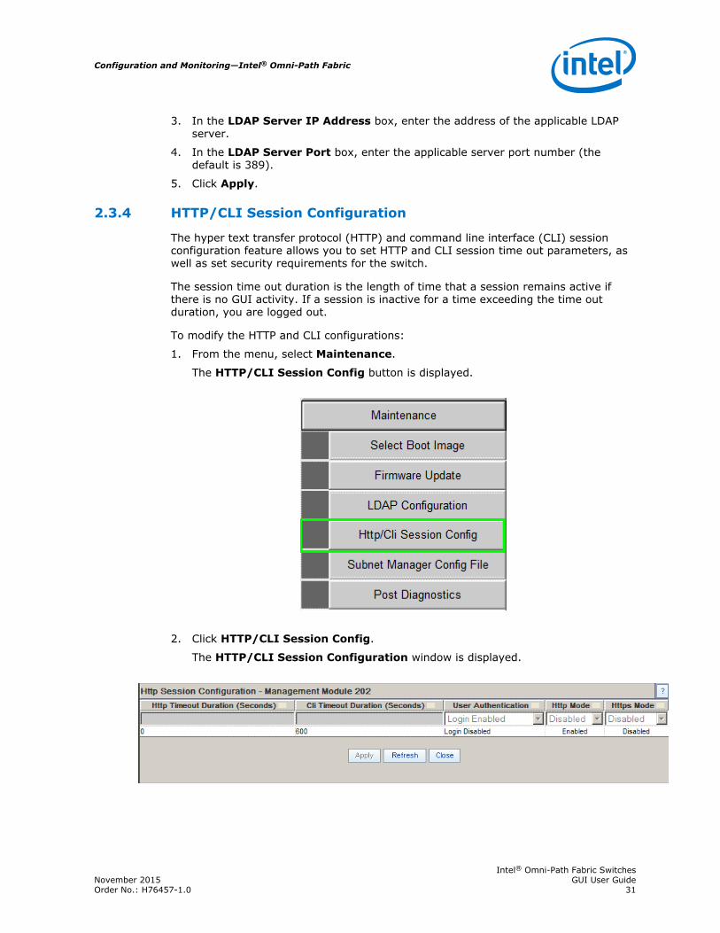
HTTP/CLI Session Configuration
The hyper text transfer protocol (HTTP) and command line interface (CLI) sessionconfiguration feature allows you to set HTTP and CLI session time out parameters, aswell as set security requirements for the switch.
The session time out duration is the length of time that a session remains active ifthere is no GUI activity. If a session is inactive for a time exceeding the time outduration, you are logged out.
To modify the HTTP and CLI configurations:
1. From the menu, select Maintenance.
The HTTP/CLI Session Config button is displayed.
2. Click HTTP/CLI Session Config.
The HTTP/CLI Session Configuration window is displayed.
2.3.4
Configuration and Monitoring—Intel® Omni-Path Fabric
Intel® Omni-Path Fabric SwitchesNovember 2015 GUI User GuideOrder No.: H76457-1.0 31

3. To modify the session time out duration (in seconds), click on the existingconfiguration. The row changes to orange.
4. In the HTTP Timeout Duration field, enter the new timeout duration, in seconds.The default is 0 seconds (no timeout).
5. In the CLI Timeout Duration field, enter the new timeout duration, in seconds.The default is 600 seconds.
6. To change the User Authentication parameter, click on the UserAuthentication list.
7. Select the preferred user authentication method.
• Login Enabled - UserName and Password must be entered, and must matchwhat is in the database of the local switch.
• User Only Required - According to the local switch database, a validusername must be entered. A password is not required.
• Login Disabled - Does not require username or password.
• LDAP - Use an LDAP server. If the user name/password validation fails tocomplete successfully, check the database of the local switch.
8. To change the HTTP Mode parameter, click on the HTTP Mode list.
9. Select Enabled or Disabled.
10. To change the HTTPs Mode parameter, click on the HTTPs Mode list.
Intel® Omni-Path Fabric—Configuration and Monitoring
Intel® Omni-Path Fabric SwitchesGUI User Guide November 201532 Order No.: H76457-1.0

11. Select Enabled or Disabled.
12. Click Apply.
Subnet Manager Configuration File
The Subnet Manager Configuration File window allows you to upload and downloadIntel® Omni-Path Fabric Suite Fabric Manager embedded subnet manager files, as wellas start and restart all applicable master and standby subnet managers using the newfile.
This window is accessible from the Maintenance menu as shown in the followingscreenshot, as well as the Configuration File Administration menu. For details, referto: Subnet Manager Configuration File on page 45.
Post Diagnostics
The Post Diagnostic feature allows you to choose tests for various switch componentsthat can be run in real time. These are tests that are not run during the power-onphase.
1. From the menu, select Maintenance.
The Post Diagnostics button is displayed.
2.3.5
2.3.6
Configuration and Monitoring—Intel® Omni-Path Fabric
Intel® Omni-Path Fabric SwitchesNovember 2015 GUI User GuideOrder No.: H76457-1.0 33

2. Click Post Diagnostics.
3. The Post Diagnostics window is displayed.
4. Select the test(s) to be run and click Run Tests.
The test results are displayed in the Test Result column. Additional information isposted to the Result-Ext column.
SNMP
The SNMP submenu allows you to view and modify SNMP trap configurationinformation.
2.4
Intel® Omni-Path Fabric—Configuration and Monitoring
Intel® Omni-Path Fabric SwitchesGUI User Guide November 201534 Order No.: H76457-1.0

Figure 8. SNMP Submenu
Target Configuration
The Target Configuration button displays the SNMP Target Configurationwindow, allowing you to view and edit existing SNMP trap destinations.
To display the Target Configuration window:
1. From the menu, select SNMP.
The Target Configuration button is displayed.
2. Select Target Configuration.
The SNMP Target Configuration window is displayed.
2.4.1
Configuration and Monitoring—Intel® Omni-Path Fabric
Intel® Omni-Path Fabric SwitchesNovember 2015 GUI User GuideOrder No.: H76457-1.0 35

The top section of the window, SNMP Target Addresses, allows you to determinewhat type of SNMP traps are sent, and where they are sent. The rows provide an areafor specifying multiple trap destinations. The middle section, SNMP Address Form,allows you to record new SNMP address information for the applicable module. Thebottom section of the window, SNMP Target Parameters, allows you to configureeach trap destination with version, optional security information, and filteringmechanisms.
The Apply button applies the current settings to either the SNMP Target Addressesor SNMP Target Parameters section. The Add button saves changes made to theSNMP Address Form section.
Note: The Target Configuration window is used for viewing and modifying existing SNMPtarget entries. It is not used for creating new target entries.
Creating a New Target Entry
To create a new target entry, use the following CLI command:
snmpTargetAddr add -n name -a addr [-p port] [-t timeout] [-r retry_count] [-l tag_list] [-v parameters] [-s storage_type]
For example, to add a trap target with the IP address 192.168.0.123 that acceptsSNMP v2c style traps:
snmpTargetAddr add -n traphost1 -a 192.168.0.123 -v "v2 params"
Or, to add the same target except using SNMP v1 traps:
snmpTargetAddr add -n traphost1 -a 192.168.0.123 -v "v1 params"
Intel® Omni-Path Fabric—Configuration and Monitoring
Intel® Omni-Path Fabric SwitchesGUI User Guide November 201536 Order No.: H76457-1.0

Target Configuration Window Field Descriptions
Descriptions for each field in the Target Configuration window are listed in thefollowing table.
Table 3. SNMP Target Configuration Fields
Name Description
SNMP Target Addresses
Address Name Specifies a unique, administrator-defined name the system uses to identifya row.
Transport Domain Specifies the transport type of the address contained in thesnmpTargetAddrTAddress object (e.g., 1.3.6.1.6.1.1 = udp,1.3.6.1.4.1.1977.200.1 = tcp).
Transport Address Specifies the IP address in dotted decimal format.Note: The combination of the Transport Domain and the Transport Address
determines the trap destination.
Port Specifies the TCP or UDP port where the SNMP trap is sent.
Timeout Specifies the time (in milliseconds) that the trap sender waits on a responsebefore re-sending the trap.
Retry Count Specifies the number of attempts to be made to send the trap after atimeout condition occurs.Note: Timeout and Retry Count are SNMP v2.c and above (not applicable
for v1 traps).
Tag List Specifies which traps should be sent to this particular destination.Note: RFC2233 specifies the link up/down traps. Including RFC2233 in the
Tag List specifies that the trap receiver gets link up/down traps.
Parameters Specifies a mapping to an entry in the SNMP Target Parameters table,determining the version of SNMP to use.
Storage Type Determines whether or not the entry is saved for each reboot of the switch.• Nonvolatile means that the value is saved, and remains after each
subsequent reboot.• Volatile or Other indicates it is not saved.
Status Indicates the current status of the row. The row may be in one of threestates:• Active• Not in service• Not Ready
Note: A status of not in service indicates that the current row is notused in the event a trap is generated by the system. Toggling atrap to not in service, which temporarily suspends trapforwarding, may be useful to keep values intact.
SNMP Target ParametersNote: Changes can only be made to rows that have a status of not in service.
Parameter Name Specifies a mapping to an entry in the SNMP Target Parameters table,determining the version of SNMP to use.
MP Model Specifies the Message Processing Model to be used when generating SNMPmessages for entry. Values for this field are 0 for SNMP v1, 1 for SNMP v2and 3 for SNMP v3.
Security Model Specifies the Security Model to be used when generating SNMP messagesusing this entry. Values for this field are 1 for SNMP v1, 2 for SNMP v2, or 3for SNMP v3.
continued...
Configuration and Monitoring—Intel® Omni-Path Fabric
Intel® Omni-Path Fabric SwitchesNovember 2015 GUI User GuideOrder No.: H76457-1.0 37

Name Description
Security Name Specifies the entity for whom SNMP messages are generated.Note: This is equivalent to the community string in an SNMP get.
Security Level One of three options:• NoAuthNoPriv: No Authentication, no privacy.• AuthNoPriv: Authentication, no privacy.• AuthPriv: Authentication and privacy
Storage Type Specifies whether or not the entry is saved for each reboot of the switch.• Nonvolatile means that the value is saved, and remains after each
subsequent reboot.• Volatile or Other indicates it is not saved.
Status Indicates the current status of the row. The row may be in one of threestates:• Active• Not in service• Not Ready
Note: A status of not in service indicates that the current row is notused in the event a trap is generated by the system. Toggling atrap to not in service, which temporarily suspends trapforwarding, may be useful to keep values intact.
Filter Status
The SNMP Filter Status window allows you to view parameters for RFC 2273 (SNMP-NOTIFICATION-MIB).
To view SNMP filter status:
1. From the menu, select SNMP
The Filter Status button is displayed.
2. Click Filter Status.
The SNMP Filter Status window is displayed.
2.4.2
Intel® Omni-Path Fabric—Configuration and Monitoring
Intel® Omni-Path Fabric SwitchesGUI User Guide November 201538 Order No.: H76457-1.0

Set Community Strings
The Set Community Strings window allows you to set two SNMP community names:
• Read Only Community Name
• Read/Write Community Name
To set the Community Strings:
1. From the menu, select SNMP.
The Set Community Strings button is displayed.
2.4.3
Configuration and Monitoring—Intel® Omni-Path Fabric
Intel® Omni-Path Fabric SwitchesNovember 2015 GUI User GuideOrder No.: H76457-1.0 39

2. Click Set Community Strings.
The Set Community Strings window is displayed.
• The first field, Read Only Comm. Name is the community string that whenspecified in an SNMP client, allows read-only access to SNMP fields exportedby the SNMP server.
• The second field, Read/Write Comm. Name is the community string thatwhen specified in an SNMP client, allows read and write access to SNMP fieldsexported by the SNMP server.
3. In each text box, enter a meaningful name (for example, public and private),and click on Apply.
Configuration File Administration
The Config File Admin menu allows you to perform various administrative tasksrelated to the configuration files for each module populating the switch.
Figure 9. Configuration File Administration Menu
Administer
The Administer window allows you to set backup and restore scenarios for theconfiguration file of applicable switch modules.
1. From the Chassis View menu, select Config File Admin.
The Administer button is displayed.
2.5
2.5.1
Intel® Omni-Path Fabric—Configuration and Monitoring
Intel® Omni-Path Fabric SwitchesGUI User Guide November 201540 Order No.: H76457-1.0

2. Click Administer.
The Configuration File Administration window is displayed.
3. Click on the module to be modified.
The row changes to orange.
4. In the Mode column, click the drop-down and select the configuration fileadministration mode for a module.
Configuration and Monitoring—Intel® Omni-Path Fabric
Intel® Omni-Path Fabric SwitchesNovember 2015 GUI User GuideOrder No.: H76457-1.0 41

The mode options include the following:
• Disabled
Following an Auto Restore of a configuration file to a module, the system setsthe module mode to Disabled. This allows you to verify that the configurationfile is correct, before returning the module to Auto Backup mode. In theDisabled mode, use the Backup and Restore buttons to either back up orrestore a configuration file.
• Auto Backup
All configuration changes to a module are automatically backed up.
• Auto Restore
The most recent configuration file is restored to a module inserted into aspecific Chassis slot. This is useful as a prerequisite to hot swapping a module.
Note: The Clear button deletes the configuration file from the switch.
5. To save, click Apply.
Host Upload/Download
The Host Up/Download window allows you to:
• Upload configuration files from a server.
• Download saved configuration files from the switch to a server.
1. From the Chassis View menu, select Config File Admin.
The Host Up/Down button is displayed.
2. Click Host Up/Down.
The Configuration File Upload/Download window is displayed.
2.5.2
Intel® Omni-Path Fabric—Configuration and Monitoring
Intel® Omni-Path Fabric SwitchesGUI User Guide November 201542 Order No.: H76457-1.0

To upload a configuration file from a server to the switch:
1. For a selected module, click the Upload button.
The Upload window is displayed.
2. Type the path to the desired server location, or click Browse to locate the correctpath.
3. Click Submit.
To download a configuration file from the switch to a server:
1. For a selected module, click the Download button. The File Download window isdisplayed.
2. Click Save.
3. In the Save As window, locate the correct path to the desired server location, andclick Save.
Trap Control
The Trap Control window allows you to set default trap scenarios related toconfiguration files.
1. From the Chassis View menu, select Config File Admin.
The Trap Control button is displayed.
2.5.3
Configuration and Monitoring—Intel® Omni-Path Fabric
Intel® Omni-Path Fabric SwitchesNovember 2015 GUI User GuideOrder No.: H76457-1.0 43

2. Click Trap Control.
The Trap Control window is displayed.
3. Select or deselect the desired trap(s).
Note: To generate an immediate trap, click the applicable Gen Trap button.
4. To save settings, click on Apply.
Note: If the trap is not selected, the Gen Trap button does not generate a trap.
Definitions for each configuration file trap are listed in the following table.
Table 4. Configuration File Traps
Name Description
cfgSrvBackupFailed The server was instructed to back up a file for aparticular slot, which failed.
cfgSrvSyncError Synchronization to the slave Management Modulefailed. The problem should be resolved andattempted manually.
continued...
Intel® Omni-Path Fabric—Configuration and Monitoring
Intel® Omni-Path Fabric SwitchesGUI User Guide November 201544 Order No.: H76457-1.0

Name Description
cfgSrvGenError A general error has occurred.
cfgSrvFileRestored The configuration files have been restored to aparticular slot.
cfgSrvFileBackedup The configuration files have been successfully backedup for a particular slot.
cfgSrvModeDisabled An event has occurred that has caused the slot modeto be set to disabled. You should resolve the errorand reset the mode to the proper value for theaffected slot.
Note: The screen shot shows the default settings for this window. You should not change thedefault settings unless instructed by Intel Customer Support.
Subnet Manager Configuration File
The Subnet Manager Configuration File window allows you to upload and downloadIntel® Omni-Path Fabric Suite Fabric Manager embedded subnet manager files, as wellas start and restart all applicable master and standby subnet managers using the newfile.
1. From the Chassis View menu, select Config File Admin.
The Subnet Manager Config File button is displayed.
2. Click Subnet Manager Config File.
The Subnet Manager Configuration window is displayed.
2.5.4
Configuration and Monitoring—Intel® Omni-Path Fabric
Intel® Omni-Path Fabric SwitchesNovember 2015 GUI User GuideOrder No.: H76457-1.0 45

3. In the Upload Config File text box: enter the path to the alternate embeddedsubnet manager file (opafm.xml). If the path is not known, you can use theBrowse... button to locate it.
4. Once the new file is located, click the Upload button.
5. In the Subnet Manager Control window for the master subnet manager, clickStop, Refresh, then Restart to have the new file become active.
6. If applicable in the Subnet Manager Control window for the slave subnetmanager, click Refresh to have the new file become active.
Chassis Traps
The Chassis Trap Control window allows you to set default trap scenarios related tothe switch.
Figure 10. Chassis Traps Menu
1. From the Chassis View menu, select Chassis Traps.
The Trap Control button is displayed.
2. Click Trap Control.
The Chassis Trap Control window is displayed.
2.6
Intel® Omni-Path Fabric—Configuration and Monitoring
Intel® Omni-Path Fabric SwitchesGUI User Guide November 201546 Order No.: H76457-1.0

3. Select or deselect the desired trap(s).
Note: To generate an immediate trap, click the applicable Gen Trap button.
4. To save settings, click on Apply.
Definitions for each chassis trap are listed in the following table.
Table 5. Chassis Traps
Name Description
Chassis Group
icsChassisTrapSystemSelfTestFailure The chassis failed one or more of its self-test(s).
icsChassisTrapSystemReboot The chassis is in the process of rebooting.
icsChassisTrapSystemMgmtSrvcStarted The internal service used to support themanagement of the chassis is operational.
icsChassisTrapSystemMgmtSrvcAborted The internal service used to support themanagement of the chassis has terminatedabnormally.
icsChassisTrapSystemSwitchFailover There was a fail over from one switch in the chassisto the other.
Slot Group
icsChassisTrapModuleNotResponding A module is not responding to HEARTBEAT pollrequests, that are issued by the internal chassismanagement service.
icsChassisTrapModuleInserted A module was inserted into the chassis.
continued...
Configuration and Monitoring—Intel® Omni-Path Fabric
Intel® Omni-Path Fabric SwitchesNovember 2015 GUI User GuideOrder No.: H76457-1.0 47
Name Description
icsChassisTrapModuleRemoved A module was removed from the chassis.
icsChassisTrapModuleFailed A module has failed and is not operational.
icsChassisTrapModuleSelfTestFailure The module failed one or more of its self tests.
icsChassisTrapModuleEEPROMReadFailure An error condition was encountered when readingthe EEPROM of the module.
icsChassisTrapModuleFPGAReadFailure An error condition was encountered when readingthe Field-Programmable Gate Array (FPGA) of themodule.
icsChassisTrapModuleBulkPowerFailure The bulk power used by a module has failed withinthe chassis.
icsChassisTrapModuleReboot The module is in the process of rebooting.
Power Group
icsChassisTrapPowerSupplyNotResponding A power supply is not responding to HEARTBEAT pollrequests that are issued by the internal chassismanagement service.
icsChassisTrapPowerSupplyInserted A power supply was inserted into the chassis.
icsChassisTrapPowerSupplyRemoved A power supply was removed from the chassis.
icsChassisTrapPowerSupplyFailed A power supply has failed and is not operational.
icsChassisTrapPowerSupplyEEPROMReadFailure An error condition was encountered when readingthe EEPROM of the power supply.
icsChassisTrapPowerSupplyFanFailed A power supply fan has failed and is not operational.
Fan Group
icsChassisTrapFanNotResponding A fan is not responding to HEARTBEAT poll requeststhat are issued by the internal chassis managementservice.
icsChassisTrapFanTrayInserted A fan was inserted into the chassis.
icsChassisTrapFanTrayRemoved A fan was removed from the chassis.
icsChassisTrapFanFailed A fan has failed and is not operational.
icsChassisTrapFanTrayEEPROMReadFailure An error condition was encountered when readingthe EEPROM of the fan tray.
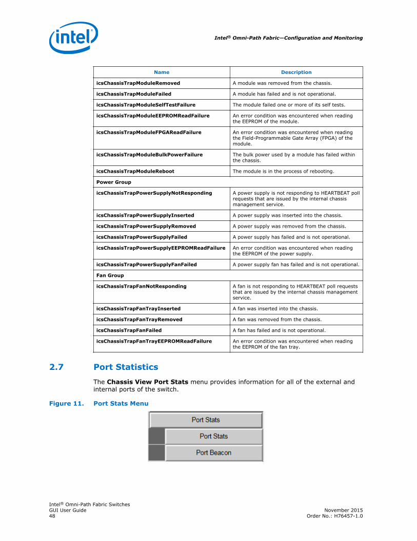
Port Statistics
The Chassis View Port Stats menu provides information for all of the external andinternal ports of the switch.
Figure 11. Port Stats Menu
2.7
Intel® Omni-Path Fabric—Configuration and Monitoring
Intel® Omni-Path Fabric SwitchesGUI User Guide November 201548 Order No.: H76457-1.0
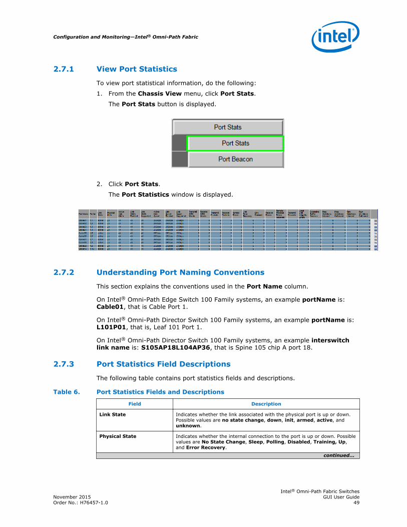
View Port Statistics
To view port statistical information, do the following:
1. From the Chassis View menu, click Port Stats.
The Port Stats button is displayed.
2. Click Port Stats.
The Port Statistics window is displayed.
Understanding Port Naming Conventions
This section explains the conventions used in the Port Name column.
On Intel® Omni-Path Edge Switch 100 Family systems, an example portName is:Cable01, that is Cable Port 1.
On Intel® Omni-Path Director Switch 100 Family systems, an example portName is:L101P01, that is, Leaf 101 Port 1.
On Intel® Omni-Path Director Switch 100 Family systems, an example interswitchlink name is: S105AP18L104AP36, that is Spine 105 chip A port 18.
Port Statistics Field Descriptions
The following table contains port statistics fields and descriptions.
Table 6. Port Statistics Fields and Descriptions
Field Description
Link State Indicates whether the link associated with the physical port is up or down.Possible values are no state change, down, init, armed, active, andunknown.
Physical State Indicates whether the internal connection to the port is up or down. Possiblevalues are No State Change, Sleep, Polling, Disabled, Training, Up,and Error Recovery.
continued...
2.7.1
2.7.2
2.7.3
Configuration and Monitoring—Intel® Omni-Path Fabric
Intel® Omni-Path Fabric SwitchesNovember 2015 GUI User GuideOrder No.: H76457-1.0 49

Field Description
Active Link Width Indicates the number of full duplex serial links that are currently being usedon a port. The current bandwidth capability of a port is determined bymultiplying this value by the Active Link Speed of this port.
Link Width Enabled Indicates the allowed link width(s) that a port can arbitrate to. Normally,this defaults to the Link Width Supported value, but can be overridden bythe subnet manager.
Link Width Supported Indicates the link width in terms of multipliers of full duplex serial linkssupported by the port.
Active Link Speed Indicates the speed of the full duplex serial link.
Link Speed Enabled Indicates the allowed link speed(s) that a port can arbitrate to. Normallythis defaults to the Link Speed Supported value, but can be overridden bythe subnet manager.
Link Speed Supported Supported link speed of the port.
Transmit 32 Bit Words Number of 32-bit data words transmitted by the port, not including flowcontrol and VCRC data.
Receive 32 Bit Words Number of 32-bit data words received by the port, not including flow controland VCRC data.
Transmit Packets Number of data packets transmitted by the port, not including flow controlpackets.
Receive Packets Number of data packets received by the port, not including flow controlpackets.
Symbol Errors Number of times a 8B10B encoding violation, or a disparity violation wasdetected. If multiple errors are detected simultaneously (in more than onelane), the counter only increments by one. The value of the counter is notincremented past 65535. The Performance Manager may reset and/orconsolidate the results of this counter.
Link Error Recovery Indicates the number of times the link error recovery process happenedsuccessfully. The value of the counter is not incremented past 65535. ThePerformance Manager may reset and/or consolidate the results of thiscounter.
Link Downed Number of times the link error recovery process failed. The value of thecounter is not incremented past 65535. The Performance Manager mayreset and/or consolidate the results of this counter.
Receive Errors Number of errors received on the port.
Remote Physical ErrorsReceived
Indicates bit errors on a link other than the physically attached link.
Transmit Discards Number of port transmit discards.
Local Link Integrity Errors Error caused by a marginal link. Depending upon the number of codeviolations, physical switch problems are detected at the physical layer.These errors are based on a count of local physical errors.
Excessive Buffer Overrun Error detected when the Overrun Errors threshold is exceeded by thenumber of consecutive flow control update periods with at least one overrunerror in each period given in the PortInfo attribute.
Pkey Violations Inbound Indicates the number of times an invalid partition key (PKey) was received.PKeys support an advanced feature for logically partitioning a physicalsubnet into logical access domains.
continued...
Intel® Omni-Path Fabric—Configuration and Monitoring
Intel® Omni-Path Fabric SwitchesGUI User Guide November 201550 Order No.: H76457-1.0

Field Description
Pkey Violations Outbound Indicates the number of times an invalid PKey was sent. PKeys support anadvanced feature for logically partitioning a physical subnet into logicalaccess domains.
Raw Violations Inbound Number of times raw inbound packet discarded.
Raw Violations Outbound Number of times raw outbound packet was discarded.
Port Beacon
The Port Beacon feature allows you to enable port LEDs to flash, assisting you inlocating a port.
1. From the Chassis menu, click Port Stats.
The Port Beacon button is displayed.
2. Click Port Beacon.
The Port Beacon window is displayed.
3. For the desired port, select the Beacon Enabled check box.
4. Click Apply.
The physical port's LED blinks. In Chassis Viewer, the Link Status LED for the portis highlighted. The arrow in the following screenshot points to the highlighted Port1.
2.7.4
Configuration and Monitoring—Intel® Omni-Path Fabric
Intel® Omni-Path Fabric SwitchesNovember 2015 GUI User GuideOrder No.: H76457-1.0 51

Time Service
The System Time Information window allows you to set the system time usingeither network time protocol (NTP) or manual overrides.
Figure 12. Time Service Menu
Setting System Time
To set the system time:
1. From the menu, select Time Service.
The Set System Time button is displayed.
2. Click Set System Time.
The System Time Information window is displayed.
2.8
2.8.1
Intel® Omni-Path Fabric—Configuration and Monitoring
Intel® Omni-Path Fabric SwitchesGUI User Guide November 201552 Order No.: H76457-1.0
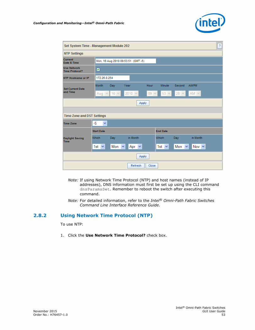
Note: If using Network Time Protocol (NTP) and host names (instead of IPaddresses), DNS information must first be set up using the CLI commanddnsParamsSet. Remember to reboot the switch after executing thiscommand.
Note: For detailed information, refer to the Intel® Omni-Path Fabric SwitchesCommand Line Interface Reference Guide.
Using Network Time Protocol (NTP)
To use NTP:
1. Click the Use Network Time Protocol? check box.
2.8.2
Configuration and Monitoring—Intel® Omni-Path Fabric
Intel® Omni-Path Fabric SwitchesNovember 2015 GUI User GuideOrder No.: H76457-1.0 53

2. Enter either the DNS host name or IP address for the NTP server.
3. To save, click on Apply.
Manually Setting System Time
To manually set the system time:
1. Make sure the Use Network Time Protocol? check box is unchecked.
2.8.3
Intel® Omni-Path Fabric—Configuration and Monitoring
Intel® Omni-Path Fabric SwitchesGUI User Guide November 201554 Order No.: H76457-1.0

2. Set the current date and time using the drop-downs for Month, Day, and Year aswell as Hour, Minute, Seconds, and AM/PM.
3. To save, click on Apply.
Setting Time Zone and Daylight Saving Time (DST)
To set time zone and daylight saving time (DST):
1. In the Time Zone drop-down, select the correct time zone based upon GreenwichMean Time (GMT).
2. Using the Which, Day, and in Month drop-downs, set the start and end dates fordaylight saving time.
3. To save, click on Apply.
Time Zone Tips
In the United States, the following time zones are in effect:
• Eastern Standard Time = GMT –5
• Central Standard Time = GMT –6
• Mountain Standard Time = GMT –7
• Pacific Standard Time = GMT -8
Daylight Saving Time Tips
For most of the United States, Daylight Saving Time (DST) begins at 2 a.m. on thesecond Sunday of March, and ends at 2 a.m. on the first Sunday in November.
For regions in the United States that do not observe DST, you should set the start andend dates in the Which, Day, and in Month settings to the exact same date.
2.8.4
2.8.4.1
2.8.4.2
Configuration and Monitoring—Intel® Omni-Path Fabric
Intel® Omni-Path Fabric SwitchesNovember 2015 GUI User GuideOrder No.: H76457-1.0 55
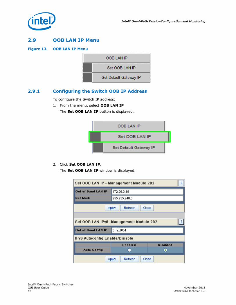
OOB LAN IP Menu
Figure 13. OOB LAN IP Menu
Configuring the Switch OOB IP Address
To configure the Switch IP address:
1. From the menu, select OOB LAN IP
The Set OOB LAN IP button is displayed.
2. Click Set OOB LAN IP.
The Set OOB LAN IP window is displayed.
2.9
2.9.1
Intel® Omni-Path Fabric—Configuration and Monitoring
Intel® Omni-Path Fabric SwitchesGUI User Guide November 201556 Order No.: H76457-1.0

3. Click the Out of Band LAN IP Address text box.
4. Enter an applicable switch IP address.
5. Click the Net Mask text box.
6. Enter an applicable switch net mask.
7. Click Apply.
If using IPv6, you can manually enter an applicable static IPv6 address (inhexadecimal format address/prefix) in the Out of Band LAN IP text box.
8. To automatically configure and assign addresses from an IPv6 router, click theAuto Config Enabled radio button.
Note: The IPv6 router must be configured to assign addresses using statelessaddress auto configuration.
9. Click Apply.
Configuring the Switch Default Gateway IP Address
The Set Default Gateway IP window allows you to configure the IP address for thedefault gateway to route packets from the OOB management port to an externalnetwork.
To configure the Switch default gateway IP address:
1. From the menu, select OOB LAN IP.
The Set Default Gateway IP button is displayed.
2.9.2
Configuration and Monitoring—Intel® Omni-Path Fabric
Intel® Omni-Path Fabric SwitchesNovember 2015 GUI User GuideOrder No.: H76457-1.0 57
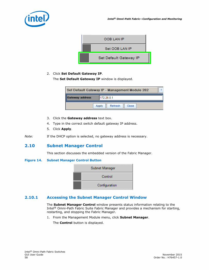
2. Click Set Default Gateway IP.
The Set Default Gateway IP window is displayed.
3. Click the Gateway address text box.
4. Type in the correct switch default gateway IP address.
5. Click Apply.
Note: If the DHCP option is selected, no gateway address is necessary.
Subnet Manager Control
This section discusses the embedded version of the Fabric Manager.
Figure 14. Subnet Manager Control Button
Accessing the Subnet Manager Control Window
The Subnet Manager Control window presents status information relating to theIntel® Omni-Path Fabric Suite Fabric Manager and provides a mechanism for starting,restarting, and stopping the Fabric Manager.
1. From the Management Module menu, click Subnet Manager.
The Control button is displayed.
2.10
2.10.1
Intel® Omni-Path Fabric—Configuration and Monitoring
Intel® Omni-Path Fabric SwitchesGUI User Guide November 201558 Order No.: H76457-1.0
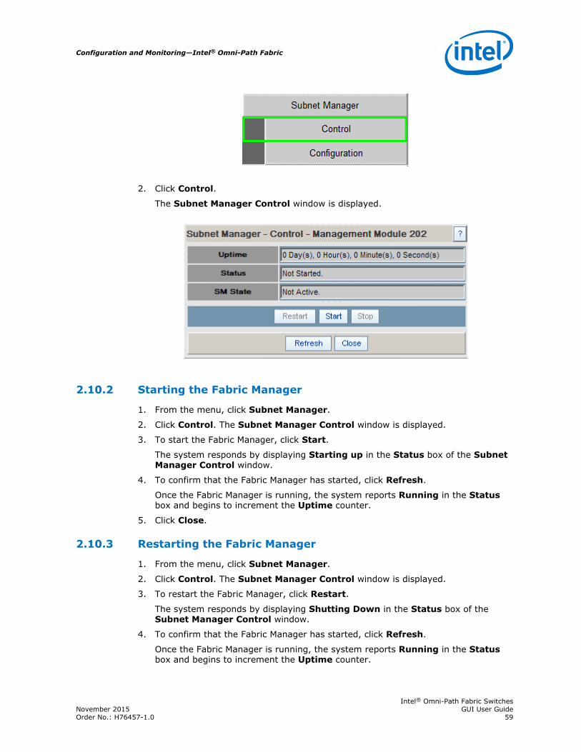
2. Click Control.
The Subnet Manager Control window is displayed.
Starting the Fabric Manager
1. From the menu, click Subnet Manager.
2. Click Control. The Subnet Manager Control window is displayed.
3. To start the Fabric Manager, click Start.
The system responds by displaying Starting up in the Status box of the SubnetManager Control window.
4. To confirm that the Fabric Manager has started, click Refresh.
Once the Fabric Manager is running, the system reports Running in the Statusbox and begins to increment the Uptime counter.
5. Click Close.
Restarting the Fabric Manager
1. From the menu, click Subnet Manager.
2. Click Control. The Subnet Manager Control window is displayed.
3. To restart the Fabric Manager, click Restart.
The system responds by displaying Shutting Down in the Status box of theSubnet Manager Control window.
4. To confirm that the Fabric Manager has started, click Refresh.
Once the Fabric Manager is running, the system reports Running in the Statusbox and begins to increment the Uptime counter.
2.10.2
2.10.3
Configuration and Monitoring—Intel® Omni-Path Fabric
Intel® Omni-Path Fabric SwitchesNovember 2015 GUI User GuideOrder No.: H76457-1.0 59

5. Click Close.
Stopping the Fabric Manager
1. From the menu, click Subnet Manager.
2. Click Control. The Subnet Manager Control window is displayed.
3. To stop the Fabric Manager, click Stop.
The system responds by displaying Shutting Down in the Status box of theSubnet Manager Control window.
4. To confirm that the Fabric Manager has shut down, click Refresh.
Once the Fabric Manager has shut down, the system reports Not Started in theStatus box of the Subnet Manager Control window.
5. Click Close.
Automatically starting the Intel® Omni-Path Fabric Suite FabricManager
To enable the Fabric Manager to automatically start at boot time:
1. From the menu, select Subnet Manager.
The Configuration button is displayed.
2. Click Configuration.
The Subnet Manager Configuration window is displayed.
3. To configure the Fabric Manager to automatically start with each boot, clickEnabled.
Note: If you want to manually activate the Fabric Manager, click Disabled.
2.10.4
2.10.5
Intel® Omni-Path Fabric—Configuration and Monitoring
Intel® Omni-Path Fabric SwitchesGUI User Guide November 201560 Order No.: H76457-1.0

4. For switches in a redundant management configuration, set the Start On Slaveoption to Disabled.
In the event that the Fabric Manager on the master Management Module isdisabled, the Fabric Manager on the slave Management Module turns onautomatically when it becomes the chassis management module.
5. Click Apply.
Configuration and Monitoring—Intel® Omni-Path Fabric
Intel® Omni-Path Fabric SwitchesNovember 2015 GUI User GuideOrder No.: H76457-1.0 61