intellectual property statement - frank's hospital...
TRANSCRIPT


I
Intellectual Property Statement Mindray DS USA, Inc. (hereinafter called Mindray DS) owns the intellectual property rights to this product and this manual. This manual may refer to information protected by copyrights or patents and does not convey any license under the copyright and the patent rights of Mindray DS, nor the rights of others.
Mindray DS intends to maintain the contents of this manual as confidential information. Disclosure of the information in this manual in any manner whatsoever without the written permission of Mindray DS is strictly forbidden. Release, amendment, reproduction, distribution, rental, adaption and translation of this manual in any manner whatsoever without the written permission of Mindray DS is strictly forbidden.
is a trademark or a registered trademark of Shenzhen Mindray Bio-Medical Electronics Co., Ltd. All third-party trademarks that appear in this manual are used solely for editorial purposes and are the property of their respective owners. Contents of this manual are subject to changes without prior notice. © 2008-2010 Mindray DS USA, Inc. All rights reserved.
WARNING
Federal Law (USA) restricts this device to sale by or on the order of a physician.

II
FOR YOUR NOTES
III
Preface
Manual Purpose This manual provides detailed information about the assembling, dissembling, testing and troubleshooting of the equipment to support effective troubleshooting and repair. It is not intended to be a comprehensive, in-depth explanation of the product architecture or technical implementation. Observance of the manual is a prerequisite for proper equipment maintenance and prevents equipment damage and personnel injury. This manual is based on the maximum configuration; therefore, some contents may not apply to your pulse oximeter. If you have any question, please contact our Customer Service Department.
Intended Audience This manual is for biomedical engineers, authorized technicians or service representatives responsible for troubleshooting, repairing and maintaining the pulse oximeter.
Revision History This manual has a revision number. This revision number changes whenever the manual is updated due to software or technical specification change. Contents of this manual are subject to change without prior notice.
Revision number: 2.0
Release time: 2010-04
Password
Maintenance password: 321

IV
FOR YOUR NOTES

1
Contents
1 Safety................................................................................................................................. 1-1 1.1 Safety Information .......................................................................................................... 1-1
1.1.1 Warnings............................................................................................................. 1-2 1.1.2 Cautions ............................................................................................................. 1-2 1.1.3 Notes .................................................................................................................. 1-2
1.2 Equipment Symbols ........................................................................................................ 1-3
2 Theory of Operation ........................................................................................................ 2-1 2.1 Introduction..................................................................................................................... 2-1 2.2 System Connections ........................................................................................................ 2-1
2.2.1 Mounting the Pulse Oximeter ............................................................................ 2-1 2.2.2 Connectors for Peripheral Devices..................................................................... 2-2
2.3 Main Unit ........................................................................................................................ 2-3 2.3.1 Main Control Unit .............................................................................................. 2-3 2.3.2 Power Supply ..................................................................................................... 2-6 2.3.3 Main Board Interfaces........................................................................................ 2-9 2.3.4 SpO2 Module.................................................................................................... 2-10 2.3.5 Charger stand ....................................................................................................2-11
3 Testing and Maintenance................................................................................................. 3-1 3.1 Introduction..................................................................................................................... 3-1
3.1.1 Recommended Frequency .................................................................................. 3-2 3.2 Visual Test ....................................................................................................................... 3-3 3.3 Power On Test ................................................................................................................. 3-3 3.4 Performance Tests ........................................................................................................... 3-4
3.4.1 SpO2 Test............................................................................................................ 3-4 3.4.2 SpO2 Test in Motion Mode................................................................................. 3-4
3.5 Electrical Safety Tests ..................................................................................................... 3-5 3.5.1 Enclosure Leakage Current Test......................................................................... 3-6 3.5.2 Patient Leakage Current Test ............................................................................. 3-6
3.6 Output Interface Test ....................................................................................................... 3-7 3.6.1 RS232 Port test................................................................................................... 3-7 3.6.2 Infrared Output Test ........................................................................................... 3-7
3.7 Program Upgrade ............................................................................................................ 3-8
4 Troubleshooting................................................................................................................ 4-1 4.1 Introduction..................................................................................................................... 4-1 4.2 Part Replacement ............................................................................................................ 4-1 4.3 Software Version Check .................................................................................................. 4-2

2
4.4 Technical Alarm Check ................................................................................................... 4-2 4.5 Troubleshooting Guide.................................................................................................... 4-3
4.5.1 Power On/Off Failures ....................................................................................... 4-3 4.5.2 Display Failures ................................................................................................. 4-3 4.5.3 Alarm Problems.................................................................................................. 4-4 4.5.4 Button Failure..................................................................................................... 4-4 4.5.5 Interface Failures................................................................................................ 4-4 4.5.6 Power Supply Failures ....................................................................................... 4-5 4.5.7 Software Upgrade Problems............................................................................... 4-5
5 Repair and Disassembly .................................................................................................. 5-1 5.1 Tools................................................................................................................................ 5-1 5.2 Preparations for Disassembly.......................................................................................... 5-1 5.3 Disassembly Guide ......................................................................................................... 5-2
5.3.1 Removing the Covers......................................................................................... 5-2 5.3.2 Removing the Main Board ................................................................................. 5-4 5.3.3 Removing the Speaker and SpO2 Communication Cable Socket....................... 5-4 5.3.4 Removing the LCD Screen ................................................................................ 5-5 5.3.5 Remove the Screen Mount ................................................................................. 5-6
6 Parts .................................................................................................................................. 6-1 6.1 Introduction..................................................................................................................... 6-1 6.2 Main Unit ........................................................................................................................ 6-2 6.3 Front Panel Assembly ..................................................................................................... 6-3 6.4 Main Board Assembly..................................................................................................... 6-4 6.5 Battery Adjusting Bracket Assembly .............................................................................. 6-5 6.6 Rear Cover Assembly...................................................................................................... 6-6 6.7 Replacement Parts........................................................................................................... 6-7
1-1
1 Safety
1.1 Safety Information
WARNING
Indicates a potential hazard or unsafe practice that, if not avoided, could result in death or serious injury.
CAUTION
Indicates a potential hazard or unsafe practice that, if not avoided, could result in death or serious injury.
NOTE
Provides maintenance tips or other useful information.
1-2
1.1.1 Warnings
WARNING
All installation operations, expansions, changes, modifications and repairs of this product should be conducted by authorized personnel only.
Always disconnect the equipment with the charger stand and remove the batteries before disassembling the equipment.
Dispose of the packaging material according to local waste control regulations and your hospital’s waste disposal protocols. Keep the packaging material out of children’s reach.
1.1.2 Cautions
CAUTION
Make sure that no electromagnetic radiation interferes with the performance of the equipment when preparing to carry out performance tests. Mobile phone, X-ray equipment and MRI devices are possible sources of interference as they may emit higher levels of electromagnetic radiation.
Before connecting the charger stand to the AC mains, check that the voltage and frequency ratings of the AC mains meet the specifications indicated on the equipment’s label or in this manual.
Protect the equipment from damage caused by drop, impact, strong vibration or other mechanical force during servicing.
1.1.3 Notes
NOTE
Refer to Operation Manual for detailed operation and other information.
1-3
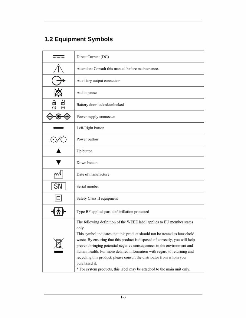
1.2 Equipment Symbols
Direct Current (DC)
Attention: Consult this manual before maintenance.
Auxiliary output connector
Audio pause
Battery door locked/unlocked
Power supply connector
Left/Right button
Power button
Up button
Down button
Date of manufacture
Serial number
Safety Class II equipment
Type BF applied part, defibrillation protected
The following definition of the WEEE label applies to EU member states only. This symbol indicates that this product should not be treated as household waste. By ensuring that this product is disposed of correctly, you will help prevent bringing potential negative consequences to the environment and human health. For more detailed information with regard to returning and recycling this product, please consult the distributor from whom you purchased it. * For system products, this label may be attached to the main unit only.

1-4
FOR YOUR NOTES
2-1
2 Theory of Operation
2.1 Introduction This pulse oximeter is designed to monitor or measure the oxygen saturation and pulse rate of single adult, pediatric and neonatal patient. The pulse oximeter also:
Presents audible and visual alarms in case of patient or equipment problems.
Enables the real-time displaying, reviewing, storing and exporting of SpO2 and PR values.
Supports Pitch Tone, which means the pitch of pulse tone rises as the oxygen saturation level increases and falls as the oxygen saturation level decreases.
Operates on either alkaline batteries or a lithium-ion battery.
Offers wired or wireless communication with a personal computer.
2.2 System Connections
2.2.1 Mounting the Pulse Oximeter The pulse oximeter can be mounted on a wall bracket or on a trolley support. The wall bracket or trolley support can be ordered optionally. Each type of mounting bracket is delivered with a complete set of mounting hardware and instructions for use. To install the pulse oximeter, refer to the instrutions for installation.
CAUTION
Use mounting brackets we supply or approve. If other compatible mounting bracket is used, be sure it can be safely applied to the pulse oximeter.
The mounting bracket should be installed by our qualified service personnel, or mechanical engineers who have adequate knowledge on it.
If other mounting solution is used, the installation personnel and the customer should verify if it can be safely applied to the pulse oximeter, and the customer assume the responsibility for any risk resulting from that.
2-2
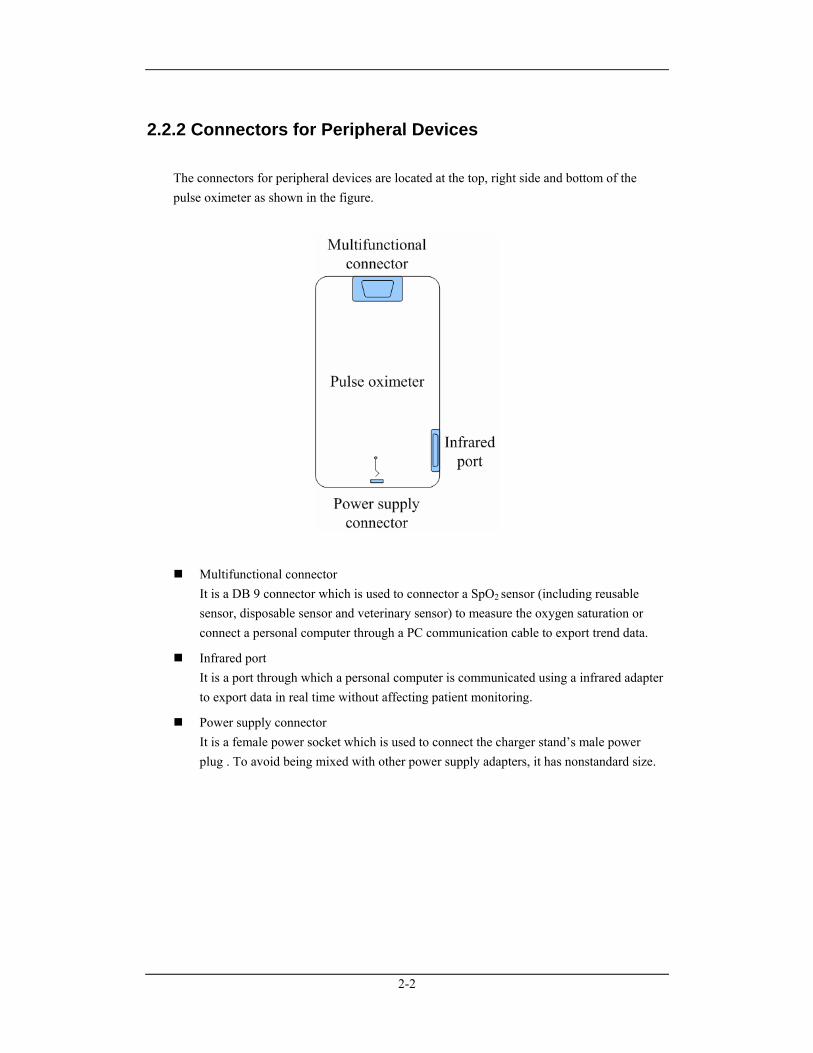
2.2.2 Connectors for Peripheral Devices The connectors for peripheral devices are located at the top, right side and bottom of the pulse oximeter as shown in the figure.
Multifunctional connector It is a DB 9 connector which is used to connector a SpO2 sensor (including reusable sensor, disposable sensor and veterinary sensor) to measure the oxygen saturation or connect a personal computer through a PC communication cable to export trend data.
Infrared port It is a port through which a personal computer is communicated using a infrared adapter to export data in real time without affecting patient monitoring.
Power supply connector It is a female power socket which is used to connect the charger stand’s male power plug . To avoid being mixed with other power supply adapters, it has nonstandard size.
2-3
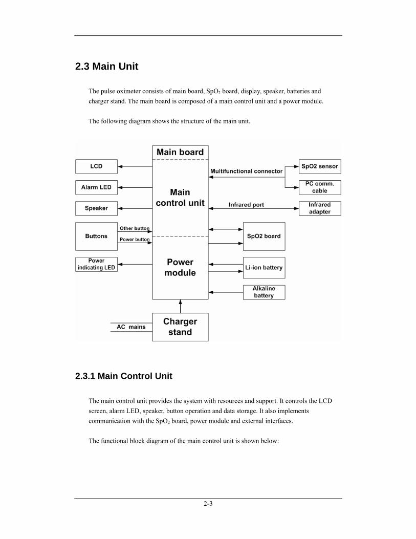
2.3 Main Unit The pulse oximeter consists of main board, SpO2 board, display, speaker, batteries and charger stand. The main board is composed of a main control unit and a power module. The following diagram shows the structure of the main unit.
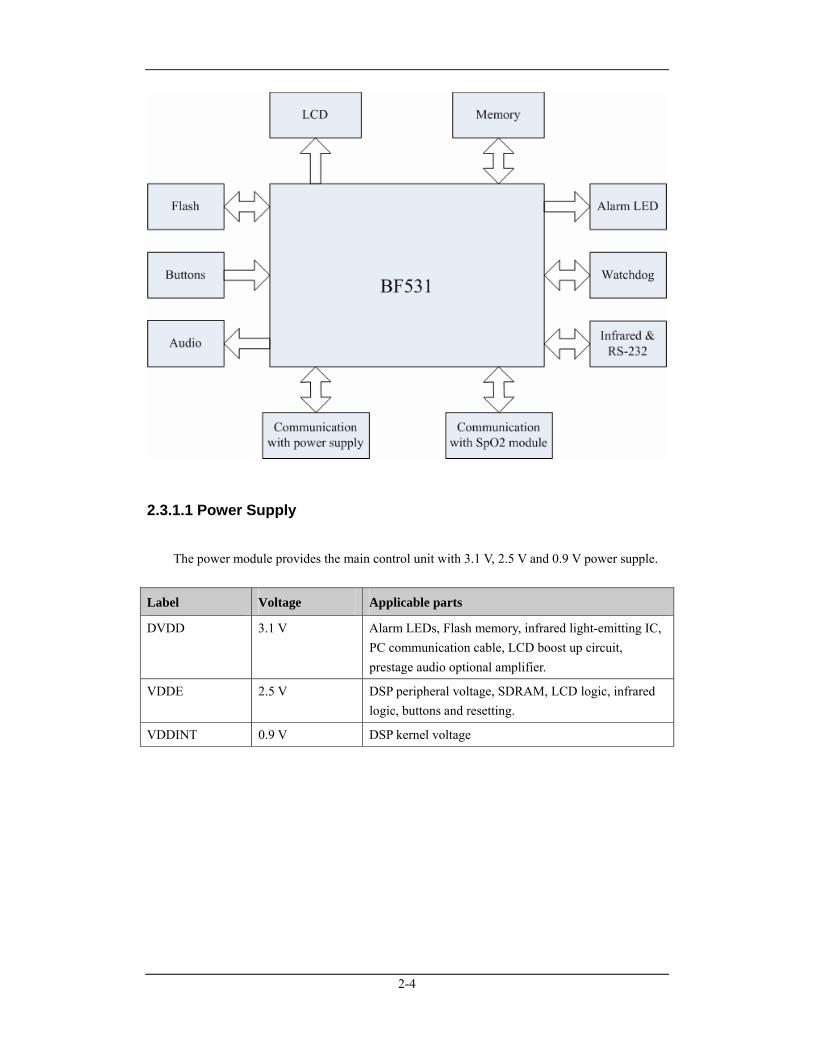
2.3.1 Main Control Unit The main control unit provides the system with resources and support. It controls the LCD screen, alarm LED, speaker, button operation and data storage. It also implements communication with the SpO2 board, power module and external interfaces. The functional block diagram of the main control unit is shown below:
2-4
2.3.1.1 Power Supply
The power module provides the main control unit with 3.1 V, 2.5 V and 0.9 V power supple.
Label Voltage Applicable parts
DVDD 3.1 V Alarm LEDs, Flash memory, infrared light-emitting IC, PC communication cable, LCD boost up circuit, prestage audio optional amplifier.
VDDE 2.5 V DSP peripheral voltage, SDRAM, LCD logic, infrared logic, buttons and resetting.
VDDINT 0.9 V DSP kernel voltage
2-5
2.3.1.2 Core Control Unit
The Core control unit consists of CPU, SDRAM and Flash memory. The CPU is ADI’s DSP BF531. Its kernel running frequency is up to 400 MHz and external frequency up to 133MHz. The kernel voltage is 0.8 V and the current consumed at 50 MHz is as low as 26mA. The oscillating frequency of the CPU clock is 11.0592 MHz and its expected frequency is 55MHz, which can be implemented through internal PLL frequency multiplication. The SDRAM provides space for program running and the Flash memory provides space for storing program, data, lingual library and configuration information. The BF531 starts directly from the Flash memory.
2.3.1.3 Man-machine Interfaces
The functions of the buttons are listed below:
Button In measurement mode In menu mode
Audio Pause button
Pauses audible alarms. Pauses audible alarms.
Up button Increases the beat volume.
Moves the cursor upwards or increases the value of selected menu item by one.
Down button Decreases the beat volume.
Moves the cursor downwards or decreases the value of selected menu item by one.
Left button Enters the main menu Enters a submenu or confirm the selection.
Right button Locks/Unlocks buttons. Returns to the previous menu or exits the current menu.
LCD screen It is a 2.4” standard QVGA (320×240) TFT LCD with a 36-pin connector. The LCD is connected with the BF531 through a bus. 4 LEDs in series are used to backlight the LCD. The maximum current is 15mA and driving voltage 13.2V. The main control board provides DC power supply for the LCD and the backlight board.
Alarm lamp The alarm lamp gives visual alarm signals which meet applicable requirements. It consists of 4 LEDs in parallel. The alarm LEDs receive electrical signal sent by the main board and convert it into optical signal which is then sent to the panel through a light conducting bar. The alarm LEDs light up in red and yellow.
2-6
Audible indicators Audio files including alarm tone, button tone and pulse tone are burned in a serial flash memory in advance. To give out a sound, the CPU reads audio data from the flash memory and controls the puse-width modulation (PWM) to give out a audible signal. The pulse oximeter supports pitch tone and multi-level volume. The speaker is connected with the main board and the audible signal is provided by the main board.
2.3.1.4 Communication Interfaces
RS232 port The RS232 port implements communication through the CPU’s UART module and the RS232 drive chip. The RS232 drive chip which is integrated in the PC communication cable is electrostatically protected. The CPU’s UART module has an external drive IC to enforce driving and ensure protection.
Infrared port The BF 531’s UART supports infrared transmission. The transmitted and received signals are connected directly to the infrared IC.
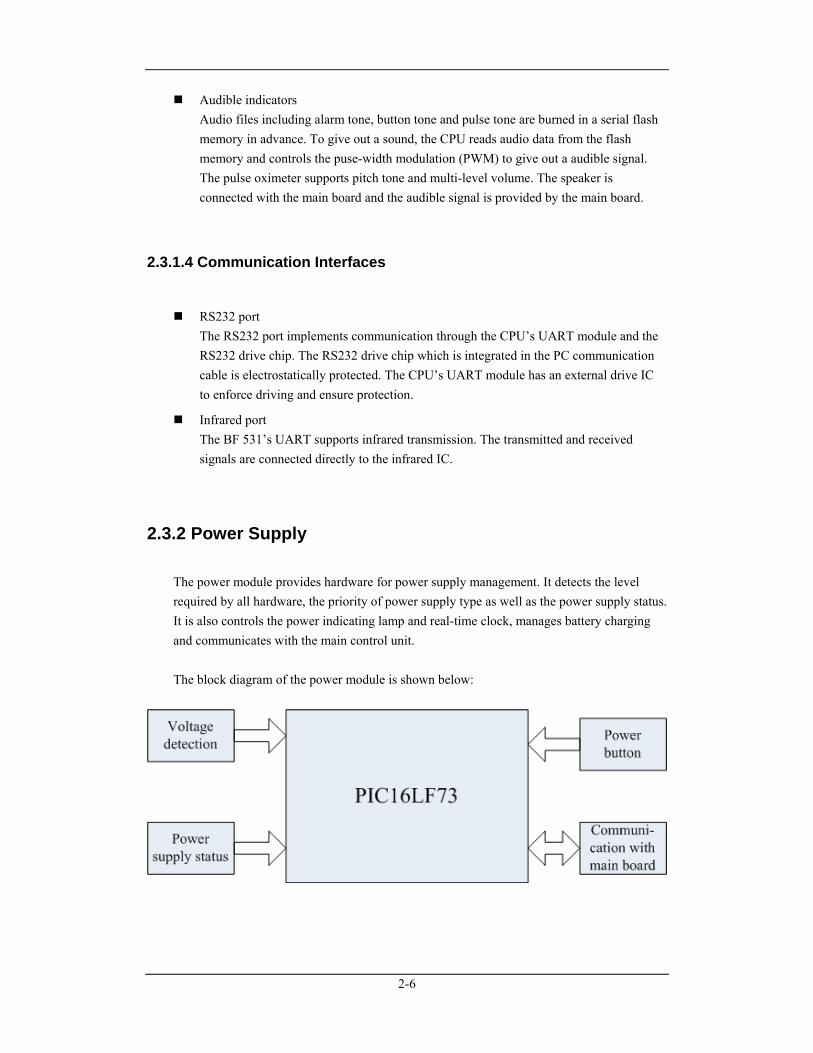
2.3.2 Power Supply The power module provides hardware for power supply management. It detects the level required by all hardware, the priority of power supply type as well as the power supply status. It is also controls the power indicating lamp and real-time clock, manages battery charging and communicates with the main control unit. The block diagram of the power module is shown below:
2-7
2.3.2.1 Input
The pulse oximeter runs on a chargeable lithium-ion battery or three alkaline AA size batteries.
Lithium-ion battery: voltage 3.7V, capacity 1800mAh;
Alkaline AA size batteries: three batteries in series, the total voltage 4.5V.
Connect the pulse oximeter to the charger stand and then connect the AC mains. The battery will be charged automatically if a lithium-ion battery is used. However, if alkaline batteries are used, the batteries will not be charged.
2.3.2.2 Output
1. SpO2 circuit
3.3V 20mA (Peak 120mA)
±2.5V 10mA
2. Main control circuit
3.1V 5mA (Peak 150mA)
2.5V 50mA (Peak 150mA)
0.9V 20mA (Peak 50mA)
3. LCD backlight and speaker are directly run by the power supply.
2.3.2.3 Power Supply Management
1. Shutdown delay
When the battery voltage is too low, an alarm message “Battery Too Low” is presented and the pulse oximeter will shut down automatically in maximum 10 minutes.
2. Run time
In the case that SpO2 is monitored continuously, audio indicators are off and backlight brightness is set to minimum, the run time of alkaline batteries is 36 hours and lithium-ion battery 24 hours, using a new, fully charged battery at ambient temperature 25℃.
3. The power supply efficiency is not less than 80 percent.
2-8
2.3.2.4 Charging the Lithium-ion Battery
The pulse oximeter is configured with a lithium-ion battery charging circuit which can detect battery charging status and provide protection against overtime, overcurrent as well as overtemperature charging. It automatically charges the battery in circle and enters into the sleeping mode when the battery is fully charged. The system identifies battery type through BC pole to avoid charging the alkaline batteries. The charge time to 90% capacity is less than 2 hours and to 100% capacity less than 3.5 hours.
2.3.2.5 Man-machine Interfaces
Button To avoid pressing the Power button by accident, you have to press and hold it for 2 seconds when you need to turn off the pulse oximeter. However, to turn on the pulse oximeter, just press it momentarily.
LED indicator The Power Indicating lamp is a LED that lights green and yellow. It is located on the main board. The status of the LED is specified as follows:
Green: when the pulse oximeter is plugged in the charger stand, and the AC mains is connected, or when the battery is fully charged if a lithium battery is used.
Yellow: when a lithium ion battery is used and is being charged.
Off: When the AC mains is not connected.
2-9
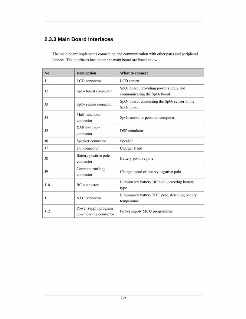
2.3.3 Main Board Interfaces The main board implements connection and communication with other parts and peripheral devices. The interfaces located on the main board are listed below:
No. Description What to connect
J1 LCD connector LCD screen
J2 SpO2 board connector SpO2 board, providing power supply and communicating the SpO2 board
J3 SpO2 sensor connector SpO2 board, connecting the SpO2 sensor to the SpO2 board
J4 Multifunctional connector
SpO2 sensor or personal computer
J5 DSP simulator connector
DSP simulator
J6 Speaker connector Speaker
J7 DC connector Charger stand
J8 Battery positive pole connector
Battery positive pole
J9 Common earthing connector
Charger stand or battery negative pole
J10 BC connector Lithium-ion battery BC pole, detecting battery type
J11 NTC connector Lithium-ion battery NTC pole, detecting battery temperature
J12 Power supply program downloading connector
Power supply MCU programmer
2-10
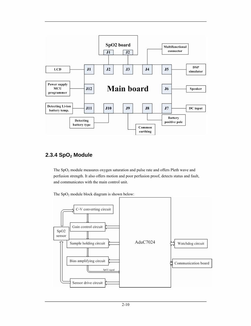
2.3.4 SpO2 Module The SpO2 module measures oxygen saturation and pulse rate and offers Pleth wave and perfusion strength. It also offers motion and poor perfusion proof, detects status and fault, and communicates with the main control unit. The SpO2 module block diagram is shown below:
2-11
2.3.4.1 Analog Circuit
The SpO2 module analog circuit adopts low power consumption design. The voltage of signal amplifying part is ±2.5V. The first stage amplifying multiple is adjustable. The sensor's driving voltage is 3.3V.
2.3.4.2 Digital Circuit
The digital circuit part mainly consists of microprocessor circuit and watchdog circuit. The ADuC7024 microprocessor used on the SpO2 module is AD’s 16/32-bit MCU. It has an 8kb SRAM and a 62kb Flash/EE memory, a 10-channel 12-bit ADC, a dual-channel 12-bit DAC and a 12-bit data acquisition system. The processor kernel is ARM7TDMI which supports 16/32-bit RISC command. The system frequency is up to 40MIPS. The ADuC7024 microprocessor supports downloading through UART and JTAG interfaces. The chip’s operating voltage is 2.7 to 3.6V and operating temperature is -40 to 125℃. The chip adopted in the watchdog circuit is TPS3823-30.
2.3.5 Charger stand The DC terminal of the charger stand is a round male power plug which is used to connect the pulse oximeter’s DC power supply connector. The AC terminal of the charger stand varies to match AC power lines of different areas. The charger stand meets the following specifications:
Input voltage 100 to 240V AC
Input frequency 50 to 60Hz
Output voltage 5V DC
Output current 1.2A

2-12
FOR YOUR NOTES
3-1
3 Testing and Maintenance
3.1 Introduction To ensure the pulse oximeter always functions normally, qualified service personnel should perform regular inspection, maintenance and test. This chapter provides testing procedures for the pulse oximeter with recommended test equipment and frequency. The service personnel should perform the testing and maintenance procedures as required and use appropriate test equipment. The testing procedures provided in this chapter are intended to verify that the pulse oximeter meets the performance and safety specifications. If the pulse oximeter fails to perform as specified in any test, repairs or replacement must be done to correct the problem. If the problem persists, contact our Customer Service Department. The service personnel may ask the manufacturer for circuit diagrams, parts and components list, operation manual, instructions for calibration and other documents needed for repairing if necessary.
CAUTION
All tests should be performed by qualified service personnel only.
Care should be taken to change the settings in the [Maintenance] menus to avoid loss of data.
Service personnel should acquaint themselves with the test tools and make sure that test tools and cables are applicable.
3-2
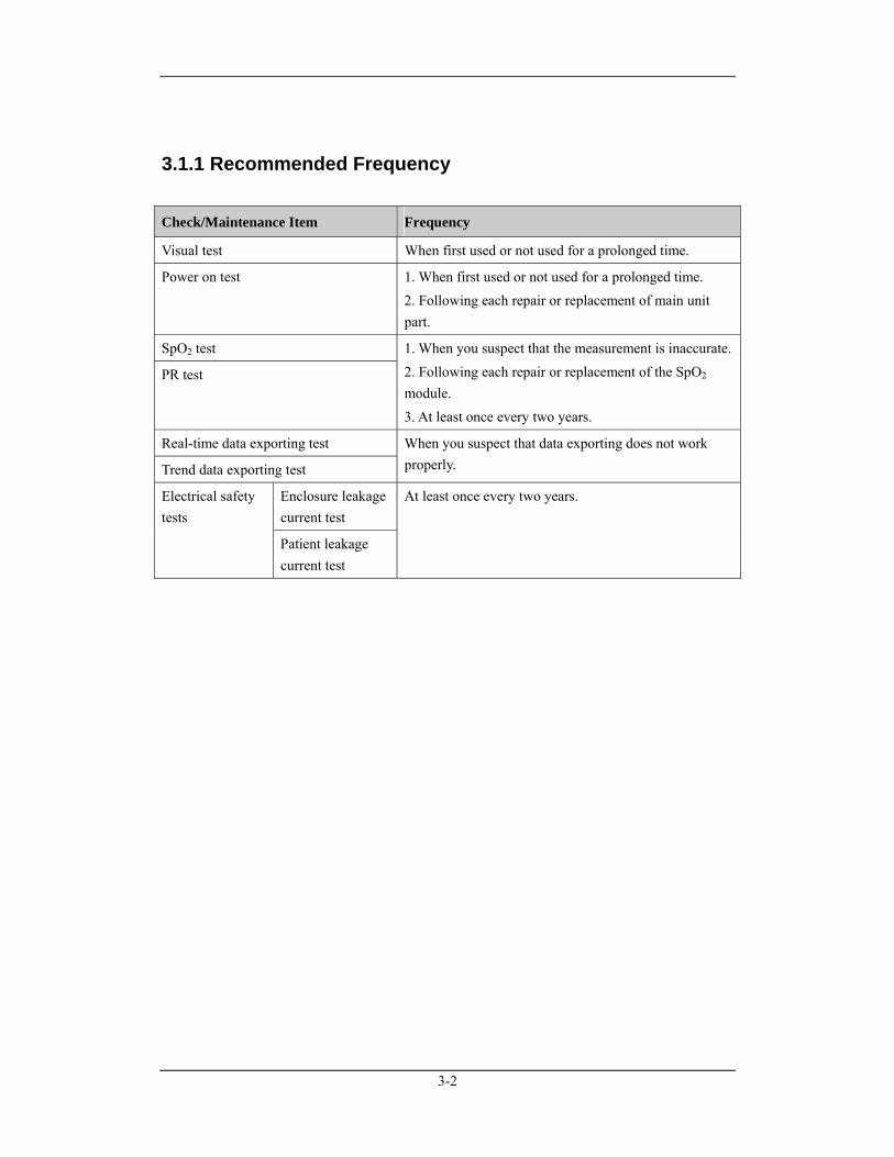
3.1.1 Recommended Frequency
Check/Maintenance Item Frequency
Visual test When first used or not used for a prolonged time.
Power on test 1. When first used or not used for a prolonged time. 2. Following each repair or replacement of main unit part.
SpO2 test
PR test
1. When you suspect that the measurement is inaccurate.2. Following each repair or replacement of the SpO2 module. 3. At least once every two years.
Real-time data exporting test
Trend data exporting test
When you suspect that data exporting does not work properly.
Enclosure leakage current test
Electrical safety tests
Patient leakage current test
At least once every two years.
3-3
3.2 Visual Test Inspect the equipment for obvious signs of damage. The test is passed if the equipment has no obvious signs of damage. Follow these guidelines when inspecting the equipment:
Carefully inspect the case, the display screen and the buttons for physical damage.
Inspect all external connections for loose connectors, bent pins or frayed cables.
Inspect all connectors on the equipment for loose connectors or bent pins.
Make sure that safety labels and name plates on the equipment are clearly legible.
3.3 Power On Test This test is to verify that the pulse oximeter powers up correctly. The test is passed if the pulse oximeter starts up following this procedure:
In the case that the alkaline AA size batteries are used,
1. Install 3 alkaline AA batteries in the pulse oximeter and press the Power button;
2. The alarm indicating lamp flashes, and then goes out; the system gives a beep and displays the startup screen;
3. The startup screen disappears and the pulse oximeter enters the main screen.By now, the pulse oximeter starts up properly.
In the case that a lithium-ion battery,
1. Remove the battery adjusting bracket and install the lithium-ion battery in the pulse oximeter;
2. Press the Power button. The alarm indicating lamp flashes, and then goes out; the system gives a beep and displays the startup screen;
3. The startup screen disappears and the pulse oximeter enters the main screen. By now, the pulse oximeter starts up properly.
4. Connect the pulse oximeter to the charger stand and then connect the AC mains. If the battery is full, the Power indicating lamp will light green. Otherwise, the battery will be charged automatically and the Power indicating lamp will light yellow. When the battery is fully charged, the Power indicating lamp turns to be green.
3-4
3.4 Performance Tests
3.4.1 SpO2 Test Required tool: SpO2 simulator
1. Connect the pulse oximeter with the SpO2 sensor.
2. Connect the SpO2 sensor with the SpO2 simulator.
3. Select the model and manufacturer of the SpO2 module under test; set SpO2 to 96% and PR to 80 bmp.
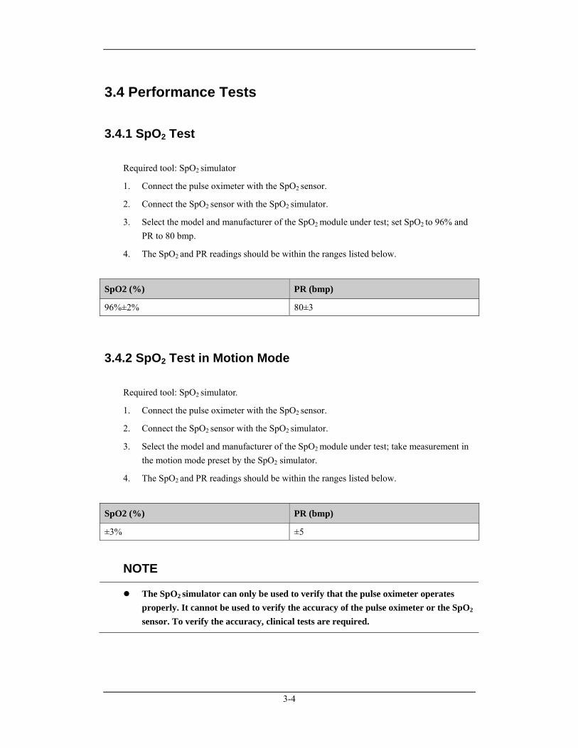
4. The SpO2 and PR readings should be within the ranges listed below.
SpO2 (%) PR (bmp)
96%±2% 80±3
3.4.2 SpO2 Test in Motion Mode Required tool: SpO2 simulator.
1. Connect the pulse oximeter with the SpO2 sensor.
2. Connect the SpO2 sensor with the SpO2 simulator.
3. Select the model and manufacturer of the SpO2 module under test; take measurement in the motion mode preset by the SpO2 simulator.
4. The SpO2 and PR readings should be within the ranges listed below.
SpO2 (%) PR (bmp)
±3% ±5
NOTE
The SpO2 simulator can only be used to verify that the pulse oximeter operates properly. It cannot be used to verify the accuracy of the pulse oximeter or the SpO2
sensor. To verify the accuracy, clinical tests are required.
3-5
3.5 Electrical Safety Tests
WARNING
Electrical safety tests are a proven means of verifying the electrical safety of the equipment. They are intended for determining potential electrical hazards. Failure to find out these hazards timely may cause personnel injury.
Commercially available test equipment such as safety analyzer, etc. can be used for electrical safety tests. Be sure that the test equipment can be safely and reliably used with the pulse oximeter before use. The service personnel should acquaint themselves with the use of the test equipment.
Electrical safety tests should meet the requirements of the latest edition of standards EN 60601-1 and UL60601.
These electrical safety tests do not supersede local requirements.
All devices using the AC mains and connected to medical equipment within patient environments must meet the requirements of the IEC 60601-1 and should be put under electrical safety tests at the frequency recommended for the pulse oximeter.
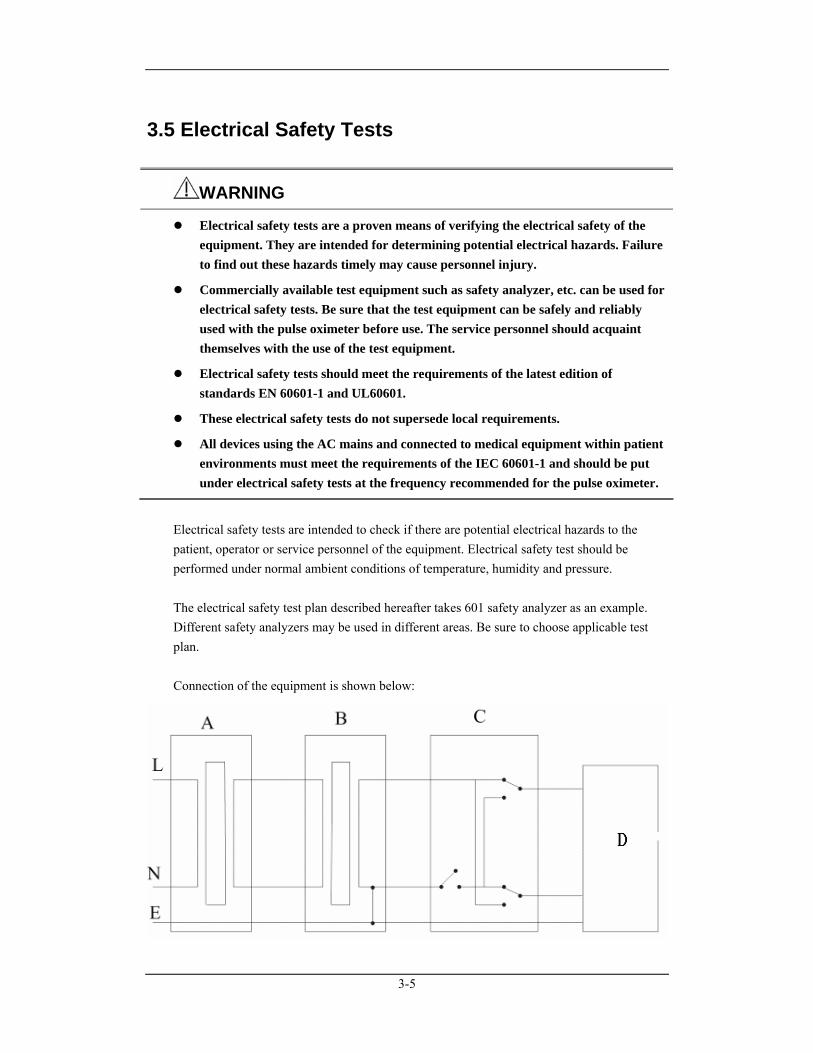
Electrical safety tests are intended to check if there are potential electrical hazards to the patient, operator or service personnel of the equipment. Electrical safety test should be performed under normal ambient conditions of temperature, humidity and pressure. The electrical safety test plan described hereafter takes 601 safety analyzer as an example. Different safety analyzers may be used in different areas. Be sure to choose applicable test plan. Connection of the equipment is shown below:
3-6
A: AC mains (programmable and frequency adjustable) B: Isolation transformer on the leakage current testing apparatus C: Safety analyzer D: Unit under test Tools required:
Safety analyzer
Isolation transformer
3.5.1 Enclosure Leakage Current Test
1. Connect the 601 safety analyzer to an AC power supply (264 V, 60 Hz).
2. Connect the SpO2 sensor to the RA terminal of the 601 safety analyzer.
3. Connect the pulse oximeter’s charger stand to the auxiliary power outlet of the 601 safety analyzer using a power cord.
4. Attach one end of the red lead to the “Red input terminal” of the analyzer, and the other end to the tinsel over the enclosure of the EUT.
5. Power on the 601 safety analyzer and then press the “5-Enclosure leakage” button on the analyzer’s panel to enter the enclosure leakage test screen.
6. Under normal condition, the enclosure leakage current should be no greater than 100 µA. Under single fault condition, it should be no greater than 300 µA.
3.5.2 Patient Leakage Current Test
1. Connect the 601 safety analyzer to an AC power supply (264 V, 60 Hz).
2. Connect the SpO2 sensor to the RA terminal of the 601 safety analyzer.
3. Connect the pulse oximeter under test to the auxiliary power outlet of the 601 safety analyzer using a power cord.
4. Power on the 601 safety analyzer and then press the “6-Patient leakage” button on the analyzer’s panel to enter the Patient leakage test screen.
5. Repeatedly press the “Applied Part” button to measure AC and DC leakage alternatively. DC leakage reading is following by “DC”.
6. Under normal status, the patient leakage current should be no greater than 10 µA. Under single fault condition, it should be no greater than 50 µA.
3-7
3.6 Output Interface Test
3.6.1 RS232 Port test
1. Use a PC communication cable to connect the multifunctional connector of the pulse oximeter under test with the RS232 port of a personal computer.
2. Select [Menu]→[Trend] to enter the trend window.
3. Press the Left button to enter the [Trend Setup] menu.
4. Set [Export Port] to [Wire].
5. Select [Export Trend] to enter the trend window; verify that trend data is exported correctly.
3.6.2 Infrared Output Test
1. Connect a personal computer with the infrared adapter and align the infrared adapter with the pulse oximeter’s infrared port.
2. Select [Menu]→[System] to enter the system menu.
3. Select [RT Export] and press the Left button to enable the infrared port.
4. Run the software on the personal computer to verify that real-time data is exported correctly.
NOTE
A communication protocol is developed and the interface is opened for infrared transmission. A third party software is required to test this item.

3-8
3.7 Program Upgrade You can upgrade the pulse oximeter software by downloading the upgrade software through a serial port. The upgrade software can run directly on a personal computer. You can upgrade the following programs by connecting the pulse oximeter with the personal computer through a PC communication cable:
Bootstrap program
System program
Multilingual library
BMP resource files (including screen icons, startup screen and standby screen)
General configurations (including password and company name)
System function configurations
SpO2 module program
For details, refer to help and instructions for program upgrade.
Caution
Disconnect the pulse oximeter from the patient and make sure the important data are saved before upgrade.
Do not shut down or power off the equipment when upgrading the bootstrap program. It may cause the equipment to break down.
Program upgrade should be performed by qualified service personnel only.
NOTE
After upgrading the bootstrap program, re-upgrade the system program and other programs to ensure compatibility.
Make sure the version of the upgrade package is what you desire. If you want to obtain the latest upgrade package, contact our Customer Service Department.
4-1
4 Troubleshooting
4.1 Introduction In this chapter, problems are listed along with possible causes and recommended corrective actions. Refer to the tables to check the pulse oximeter, identify and eliminate the troubles. The troubles we list here are frequently arisen difficulties and the actions we recommend can correct most problems, but not all of them. For more information on troubleshooting, contact our Customer Service Department.
4.2 Part Replacement Printed circuit board (PCB) assemblies, major parts and components of the pulse oximeter are replaceable. Once you isolate a suspected PCB, follow the instructions in 5 Repair and Disassembly to replace the PCB with a known good one. Check that the trouble symptom disappears or the pulse oximeter passes all performance tests. Defective PCB assembly can be sent to us for repair. If the trouble symptom persists, swap the replacement PCB and the suspected malfunctioning PCB (the original PCB that was installed when you start troubleshooting) and continue troubleshooting as directed in this chapter. To obtain information on replacement parts or order them, refer to parts by the part names and part number listed in 6 Parts.
4-2
4.3 Software Version Check Some troubleshooting tasks may require you to identify the configuration and software version of your pulse oximeter for software compatibility. For detailed information on version compatibility, contact our Customer Service Department. To check the version information,
1. Select [Menu]→[System]→[Maintenance >>]→enter required password→[Version >>]. In the [Version] menu, you can view PCBA version and copyright information.
2. Select [Menu]→[System]→[Maintenance >>]→enter required password→[Version >>]→[Software version >>]. In the [Software version] menu, you can view system software version and module version.
4.4 Technical Alarm Check Before troubleshooting the pulse oximeter, check for technical alarm message. If an alarm message is presented, eliminate the technical alarm first. For detailed information on technical alarm message, possible cause and corrective action, refer to the pulse oximeter’s Operation Manual.
4-3
4.5 Troubleshooting Guide
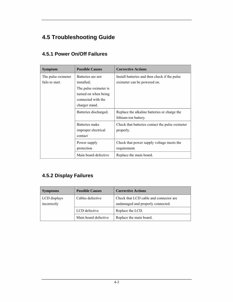
4.5.1 Power On/Off Failures
Symptom Possible Causes Corrective Actions
Batteries are not installed; The pulse oximeter is turned on when being connected with the charger stand.
Install batteries and then check if the pulse oximeter can be powered on.
Batteries discharged. Replace the alkaline batteries or charge the lithium-ion battery.
Batteries make improper electrical contact
Check that batteries contact the pulse oximeter properly.
Power supply protection
Check that power supply voltage meets the requirement.
The pulse oximeter fails to start.
Main board defective Replace the main board.
4.5.2 Display Failures
Symptoms Possible Causes Corrective Actions
Cables defective Check that LCD cable and connector are undamaged and properly connected.
LCD defective Replace the LCD.
LCD displays incorrectly
Main board defective Replace the main board.
4-4
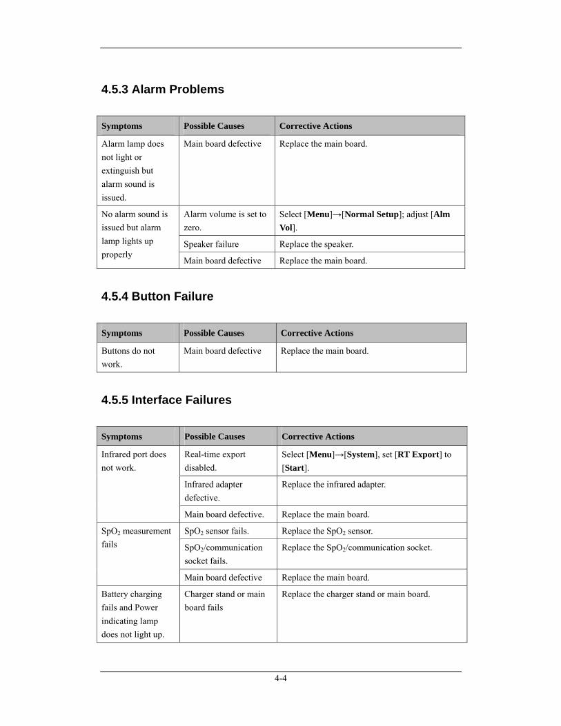
4.5.3 Alarm Problems
Symptoms Possible Causes Corrective Actions
Alarm lamp does not light or extinguish but alarm sound is issued.
Main board defective Replace the main board.
Alarm volume is set to zero.
Select [Menu]→[Normal Setup]; adjust [Alm Vol].
Speaker failure Replace the speaker.
No alarm sound is issued but alarm lamp lights up properly
Main board defective Replace the main board.
4.5.4 Button Failure
Symptoms Possible Causes Corrective Actions
Buttons do not work.
Main board defective Replace the main board.
4.5.5 Interface Failures
Symptoms Possible Causes Corrective Actions
Real-time export disabled.
Select [Menu]→[System], set [RT Export] to [Start].
Infrared adapter defective.
Replace the infrared adapter.
Infrared port does not work.
Main board defective. Replace the main board.
SpO2 sensor fails. Replace the SpO2 sensor.
SpO2/communication socket fails.
Replace the SpO2/communication socket.
SpO2 measurement fails
Main board defective Replace the main board.
Battery charging fails and Power indicating lamp does not light up.
Charger stand or main board fails
Replace the charger stand or main board.
4-5
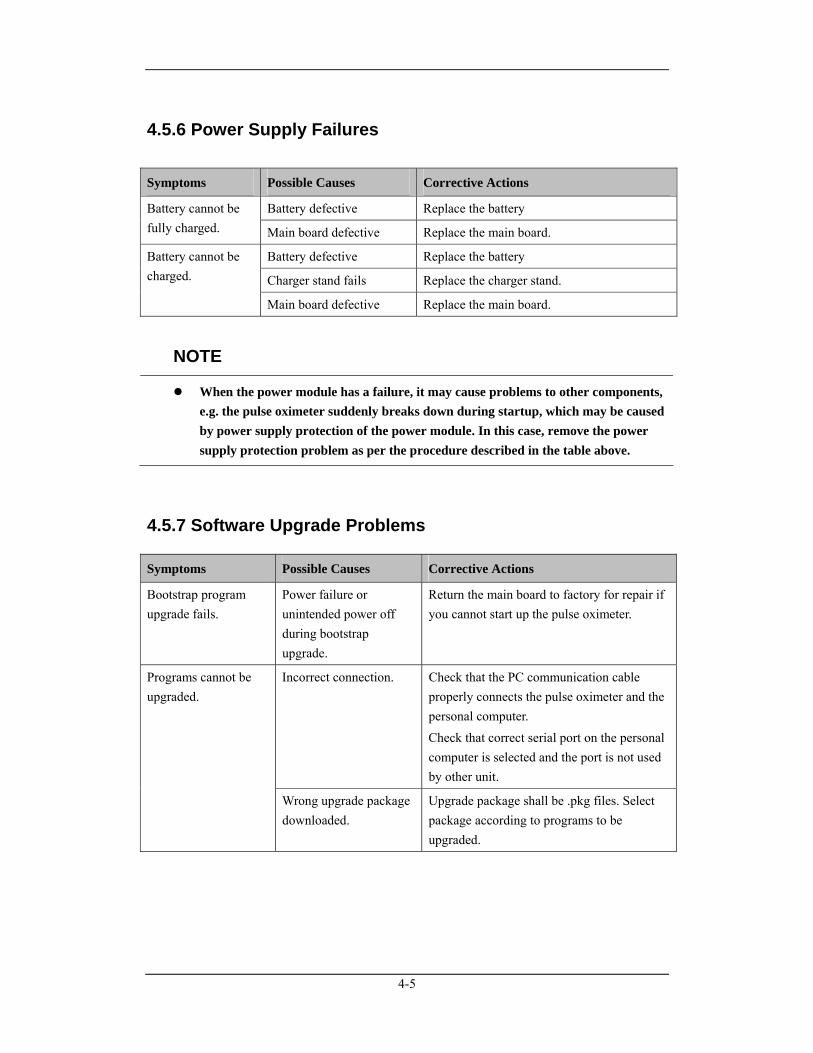
4.5.6 Power Supply Failures
Symptoms Possible Causes Corrective Actions
Battery defective Replace the battery Battery cannot be fully charged. Main board defective Replace the main board.
Battery defective Replace the battery
Charger stand fails Replace the charger stand.
Battery cannot be charged.
Main board defective Replace the main board.
NOTE
When the power module has a failure, it may cause problems to other components, e.g. the pulse oximeter suddenly breaks down during startup, which may be caused by power supply protection of the power module. In this case, remove the power supply protection problem as per the procedure described in the table above.
4.5.7 Software Upgrade Problems
Symptoms Possible Causes Corrective Actions
Bootstrap program upgrade fails.
Power failure or unintended power off during bootstrap upgrade.
Return the main board to factory for repair if you cannot start up the pulse oximeter.
Incorrect connection. Check that the PC communication cable properly connects the pulse oximeter and the personal computer. Check that correct serial port on the personal computer is selected and the port is not used by other unit.
Programs cannot be upgraded.
Wrong upgrade package downloaded.
Upgrade package shall be .pkg files. Select package according to programs to be upgraded.

4-6
FOR YOUR NOTES
5-1
5 Repair and Disassembly
5.1 Tools The following tools may be required for disassembly and repair:
Small screwdriver
Sharp-nose pliers
Tweezers
5.2 Preparations for Disassembly Before disassembling the pulse oximeter, stop monitoring the patient, turn off the pulse oximeter and disconnect all the accessories and peripheral devices.
CAUTION
Before disassembling the pulse oximeter, be sure to eliminate the static charges first. When disassembling the parts labeled with static-sensitive symbols, make sure to wear electrostatic discharge protection such as an antistatic wristband or gloves to avoid damaging the equipment.
Put the cables or wires in place when reassemble the pulse oximeter to avoid short circuit.
When assembling the pulse oximeter, be sure to select proper screws. If an unfit screw is tightened by force, the pulse oximeter may be damaged and the screw or the part may fall off during use, resulting in unpredictable damage or human injury
Be sure to follow correct sequence to disassembly the pulse oximeter. Otherwise, the pulse oximeter may be damaged permanently.
Be sure to disconnect all the cables before disassembling any parts. Be sure not to damage any cables or connectors.
Be sure to place the removed screws and parts properly for convenient reassembly. Protect them from dropping, contaminating or losing.
5-2
5.3 Disassembly Guide
5.3.1 Removing the Covers
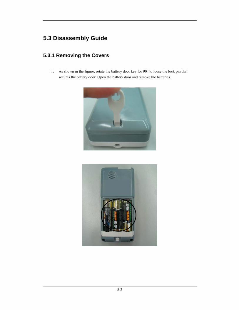
1. As shown in the figure, rotate the battery door key for 90° to loose the lock pin that secures the battery door. Open the battery door and remove the batteries.
5-3
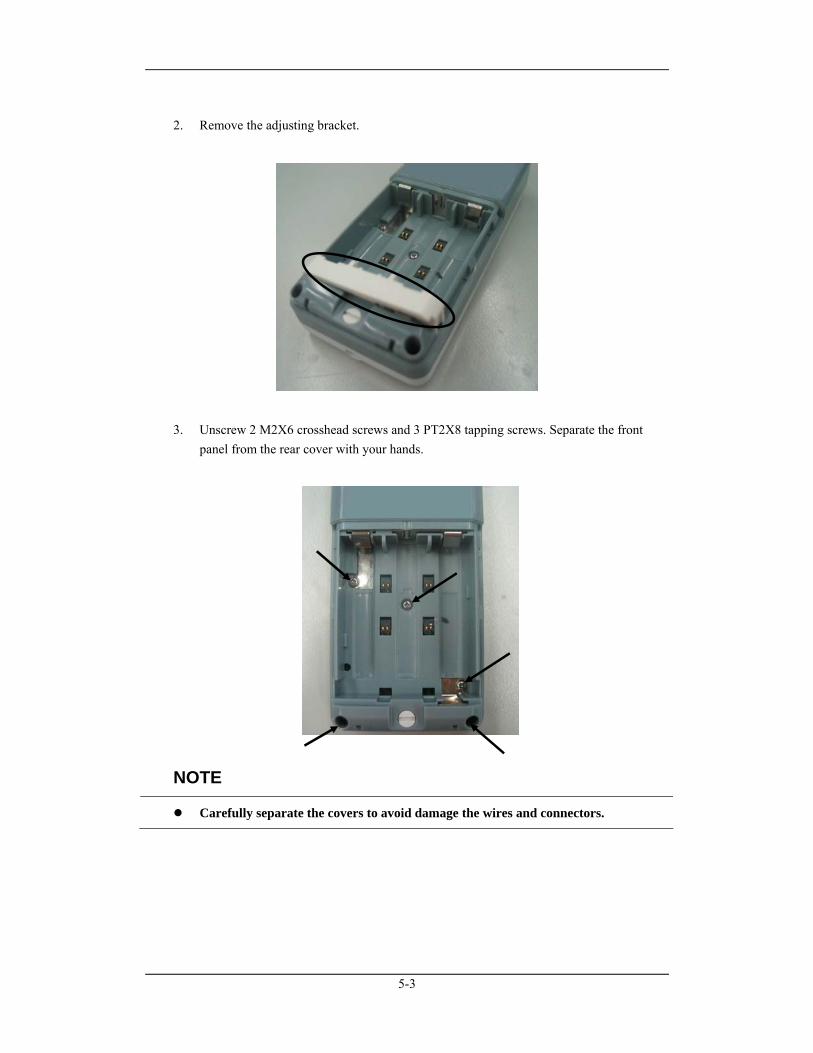
2. Remove the adjusting bracket.
3. Unscrew 2 M2X6 crosshead screws and 3 PT2X8 tapping screws. Separate the front panel from the rear cover with your hands.
NOTE
Carefully separate the covers to avoid damage the wires and connectors.
5-4
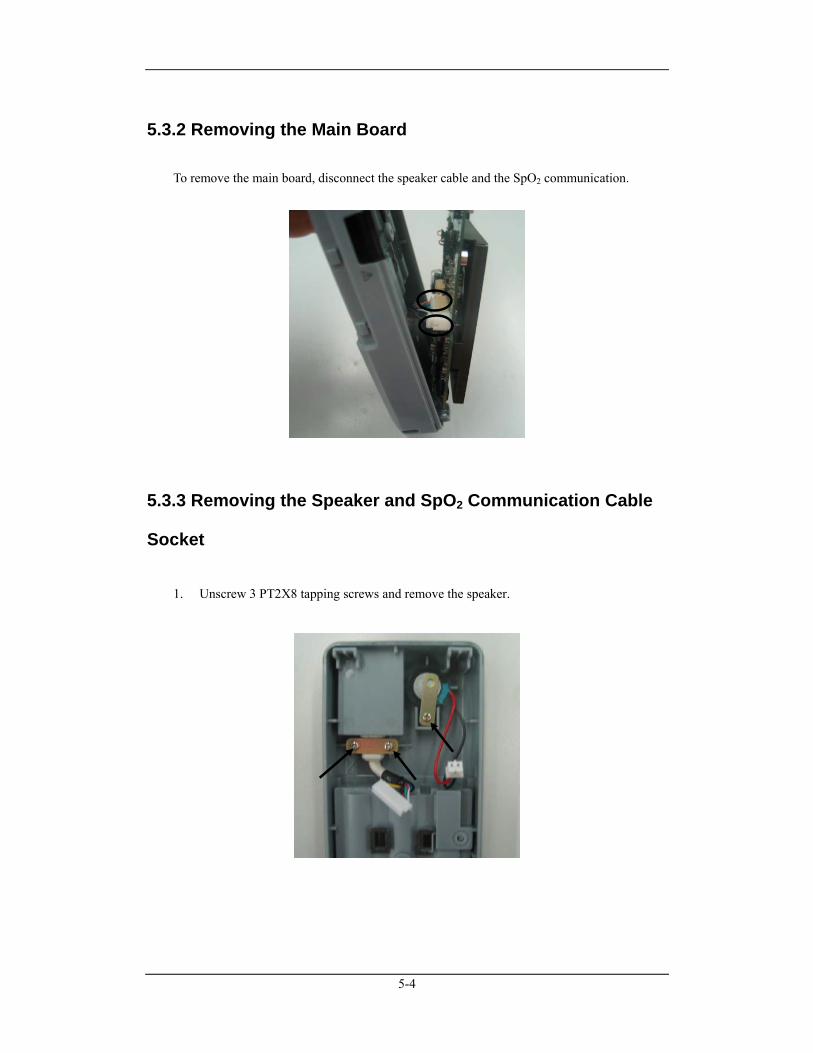
5.3.2 Removing the Main Board To remove the main board, disconnect the speaker cable and the SpO2 communication.
5.3.3 Removing the Speaker and SpO2 Communication Cable
Socket
1. Unscrew 3 PT2X8 tapping screws and remove the speaker.

5-5
2. Thrust the end of the SpO2 communication cable socket and push it out.
5.3.4 Removing the LCD Screen Pry the LCD screen at the top right corner with tweezers, disconnect the flexible cable socket and remove the LCD screen.
5-6
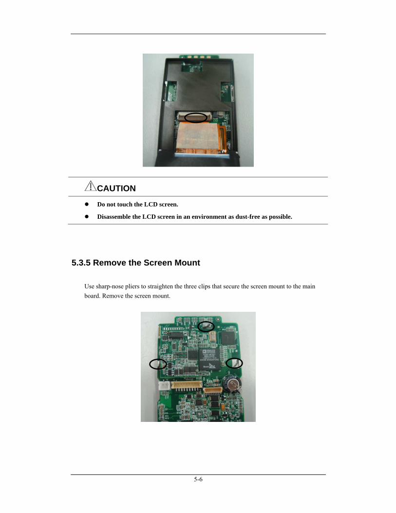
CAUTION
Do not touch the LCD screen.
Disassemble the LCD screen in an environment as dust-free as possible.
5.3.5 Remove the Screen Mount Use sharp-nose pliers to straighten the three clips that secure the screen mount to the main board. Remove the screen mount.
6-1
6 Parts
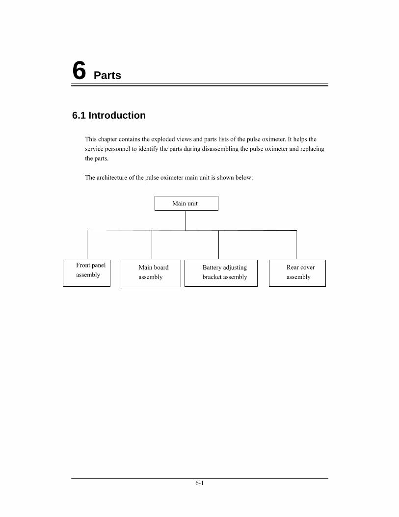
6.1 Introduction This chapter contains the exploded views and parts lists of the pulse oximeter. It helps the service personnel to identify the parts during disassembling the pulse oximeter and replacing the parts. The architecture of the pulse oximeter main unit is shown below:
Main unit
Front panel assembly
Main board assembly
Battery adjusting bracket assembly
Rear cover assembly
6-2
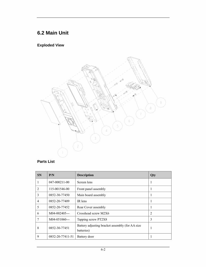
6.2 Main Unit
Exploded View
Parts List
SN P/N Description Qty
1 047-000211-00 Screen lens 1
2 115-001546-00 Front panel assembly 1
3 0852-30-77450 Main board assembly 1
4 0852-20-77409 IR lens 1
5 0852-20-77452 Rear Cover assembly 1
6 M04-002405--- Crosshead screw M2X6 2
7 M04-051060--- Tapping screw PT2X8 3
8 0852-30-77451 Battery adjusting bracket assembly (for AA size batteries)
1
9 0852-20-77411-51 Battery door 1
6-3
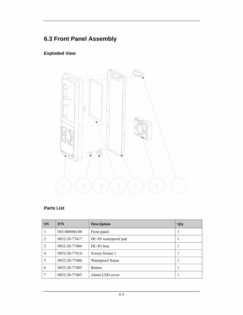
6.3 Front Panel Assembly
Exploded View
Parts List
SN P/N Description Qty
1 043-000086-00 Front panel 1
2 0852-20-77417 DC-IN waterproof pad 1
3 0852-20-77404 DC-IN lens 1
4 0852-20-77414 Screen fixture 1 1
5 0852-20-77406 Waterproof frame 1
6 0852-20-77405 Button 1
7 0852-20-77403 Alarm LED cover 1
6-4
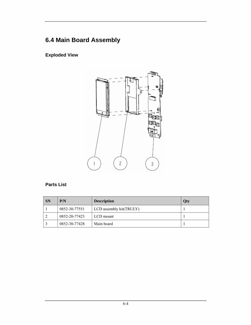
6.4 Main Board Assembly
Exploded View
Parts List
SN P/N Description Qty
1 0852-30-77551 LCD assembly kit(TRULY) 1
2 0852-20-77423 LCD mount 1
3 0852-30-77428 Main board 1
6-5
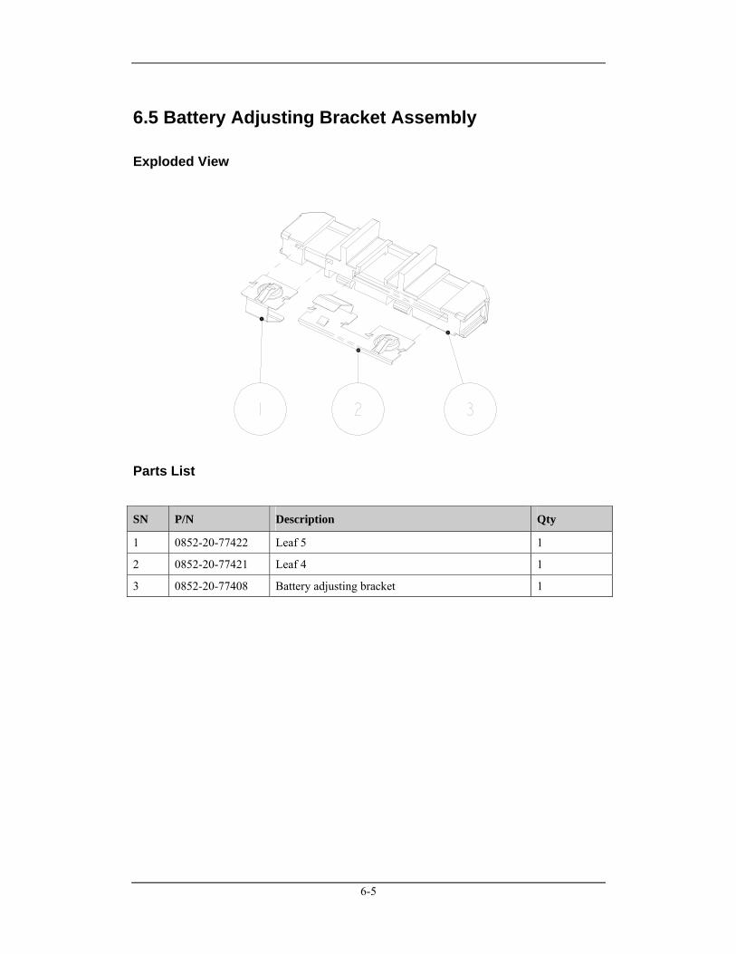
6.5 Battery Adjusting Bracket Assembly
Exploded View
Parts List
SN P/N Description Qty
1 0852-20-77422 Leaf 5 1
2 0852-20-77421 Leaf 4 1
3 0852-20-77408 Battery adjusting bracket 1
6-6
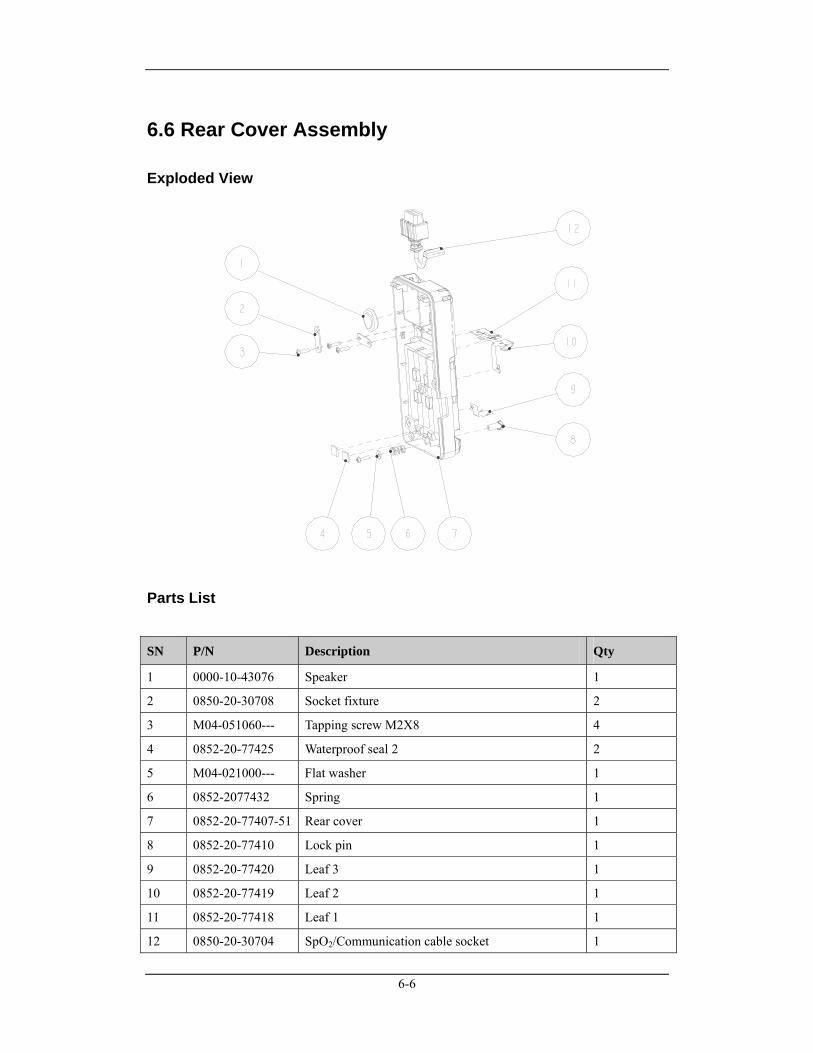
6.6 Rear Cover Assembly
Exploded View
Parts List
SN P/N Description Qty
1 0000-10-43076 Speaker 1
2 0850-20-30708 Socket fixture 2
3 M04-051060--- Tapping screw M2X8 4
4 0852-20-77425 Waterproof seal 2 2
5 M04-021000--- Flat washer 1
6 0852-2077432 Spring 1
7 0852-20-77407-51 Rear cover 1
8 0852-20-77410 Lock pin 1
9 0852-20-77420 Leaf 3 1
10 0852-20-77419 Leaf 2 1
11 0852-20-77418 Leaf 1 1
12 0850-20-30704 SpO2/Communication cable socket 1
6-7
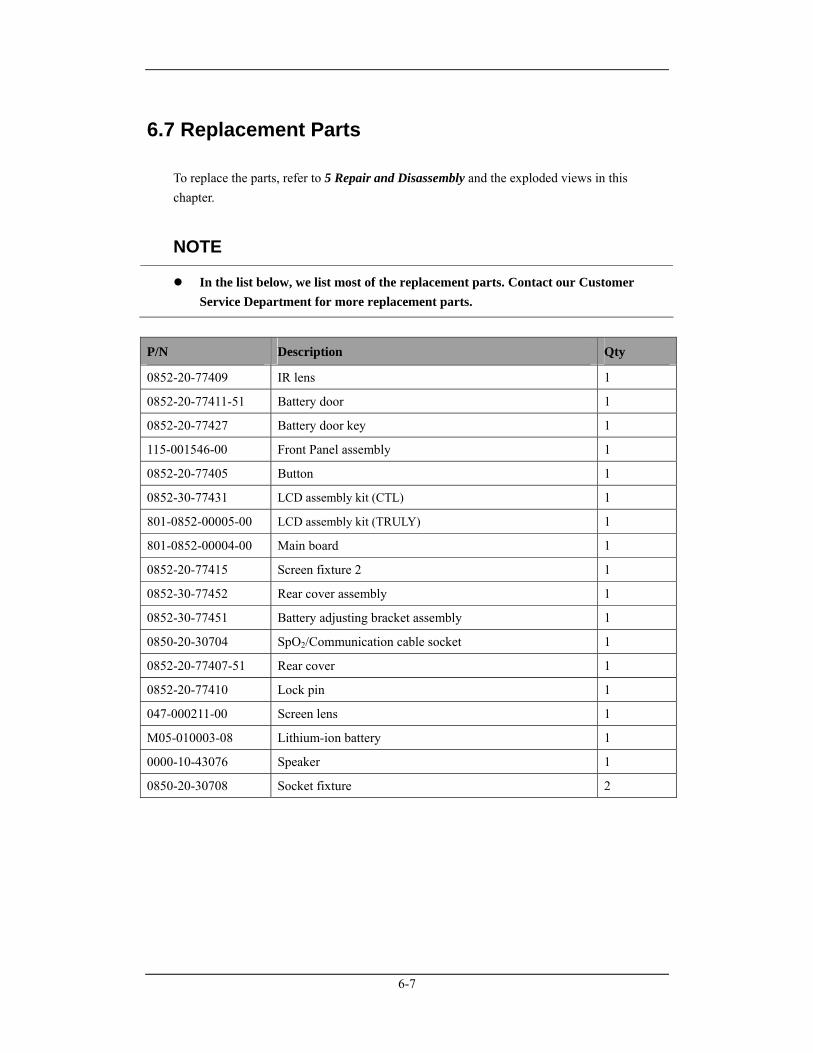
6.7 Replacement Parts To replace the parts, refer to 5 Repair and Disassembly and the exploded views in this chapter.
NOTE
In the list below, we list most of the replacement parts. Contact our Customer Service Department for more replacement parts.
P/N Description Qty
0852-20-77409 IR lens 1
0852-20-77411-51 Battery door 1
0852-20-77427 Battery door key 1
115-001546-00 Front Panel assembly 1
0852-20-77405 Button 1
0852-30-77431 LCD assembly kit (CTL) 1
801-0852-00005-00 LCD assembly kit (TRULY) 1
801-0852-00004-00 Main board 1
0852-20-77415 Screen fixture 2 1
0852-30-77452 Rear cover assembly 1
0852-30-77451 Battery adjusting bracket assembly 1
0850-20-30704 SpO2/Communication cable socket 1
0852-20-77407-51 Rear cover 1
0852-20-77410 Lock pin 1
047-000211-00 Screen lens 1
M05-010003-08 Lithium-ion battery 1
0000-10-43076 Speaker 1
0850-20-30708 Socket fixture 2


P/N: 046-000177-00 (2.0)