intentionally induced swirling flow may improve the hemodynamic … · 2019-09-28 · intentionally...
TRANSCRIPT
Intentionally Induced Swirling Flow May Improve theHemodynamic Performance of Coronary Bifurcation
Stenting
Anqiang Sun, PhD, Yubo Fan, PhD, and Xiaoyan Deng,* PhD
Objectives and Background: Bifurcation stenting represents a challenge for the highrate of restenosis that has close correlations with local hemodynamics. This studysought to test the hypothesis that by intentionally inducing swirling flow the hemody-namic performance of bifurcation stenting can be improved. Methods: The hemodynam-ics of bifurcation stenting with and without swirling flows were numerically simulatedand compared. Results: The results revealed that swirling flow significantly suppressedflow disturbance of blood at the bifurcation and WSS at two critical regions, the outerwall of the bifurcation ostium and the floor wall opposite the branching, was enhanced.Conclusions: This study therefore suggests that intentionally inducing swirling flowmight be a good strategy in bifurcation stenting. VC 2011 Wiley Periodicals, Inc.
Key words: restenosis; atherosclerosis; branching vessels; wall shear stress
INTRODUCTION
Coronary bifurcations are locations that are prone todevelop atherosclerotic lesions. Because of their com-plex configurations, atherosclerotic stenoses at coronarybifurcations are difficult to treat with conventional bal-loon angioplasty [1]. The restenosis rate was more than50% both in the main branch and the side branch atthe early balloon angioplasty stage [2]. To solve thisproblem, later on percutaneous intervention such asstenting were adopted for the treatment. But both theprocedural failure rate and long-term restenosis ratewere all reported to be higher than that of nonbifurca-tion interventions [3,4]. To overcome this obviousshortcoming, intracoronary stents was introduced andmultiple combinations of balloons and stents have beenexplored [5–8]. However, the late follow-ups show thatthe restenosis rate of coronary bifurcation stenting isstill relatively high. Bifurcation stenting is challengingeven in the drug eluting stenting era today.
It has been well documented that the initiation andprogression of restenosis is often related to alteredhemodynamics with flow disturbance resulting fromthe stent deployed, which always involves low wallshear stress (WSS) with high oscillating shear index[9–11]. Due to the already complex geometrical config-uration of coronary bifurcations, the implantation ofstents can severely compromise blood flow at the bifur-cations, resulting in even higher restenosis rate there.
It has been proven that local hemodynamics is very sen-sitive to the geometry and structure of a stent [12]. There-
fore, stent design appears to play a very important role intissue hyperplastic response and the occurrence of resteno-sis [13]. This should be more so for bifurcation stenting.In the very recent literature [14], James E. Moore Jr.emphasized the necessity of developing the hemodynamicperformance of coronary bifurcation strategy.
Hemodynamic studies revealed that the blood flowin the aortic arch took a form with a corkscrew-likepattern [15–17]. The ascending aorta is not the onlyplace in the circulation where spiral or swirling bloodflow was observed. Stonebridge and Brophy [18] evi-denced the existence of spiral blood-flows in human
Key Laboratory for Biomechanics and Mechanobiology ofMinistry of Education, School of Biological Science and Medi-cal Engineering, Beihang University, Beijing 100191, China
Conflict of interest: Nothing to report.
Grant sponsor: National Natural Science Research Foundation of
China; grant numbers: 10632010; 11072023; 10925208. Grant spon-
sor: Innovation Foundation of BUAA.
*Correspondence to: Xiaoyan Deng, PhD, School of Biological Sci-
ence and Medical Engineering, Beihang University, Beijing 100191,
China. E-mail: [email protected]
Received 24 November 2010; Revision accepted 20 December 2010
DOI 10.1002/ccd.22969
Published online 21 July 2011 in Wiley Online Library
(wileyonlinelibrary.com)
VC 2011 Wiley Periodicals, Inc.
Catheterization and Cardiovascular Interventions 79:371–377 (2012)

infrainguinal blood vessels and found that out of the75 arteries examined, 51 had spiral folds on theirendo-luminal surfaces. Combining with the observa-tions by others [19–21], they argued that spiral bloodflow was a normal physiological flow phenomenon, atleast in parts of the circulation. Frazin et al. [22] evenbelieved that spiral or helical flow may account for asignificant amount of normal organ perfusion frombranch vessels due to the centripetal spin induced inblood. Stonebridge and Brophy [18] hypothesized thatthe rifled endo-luminal surfaces of the arteries mightreflect inherent structural features in the elastic wall ofthe vessels and spiral flow could exert a beneficialeffect on the mechanisms of endothelial damage repair.The study by Caro et al. [23] had supported this hy-pothesis and demonstrated that spiral flow may lead torelative uniformity of wall shear, and inhibition of flowstagnation, separation and instability.
Inspired by the aforementioned findings, we hypothe-size that by intentionally inducing swirling flow in cor-onary bifurcation stentings, flow disturbance with vor-tex formation and flow stagnation might be suppressed.As a result, the restenosis rate might be reduced. To
test the hypothesis, we numerically compared thehemodynamics of bifurcation stenting with and withoutswirling flows.
METHODS
A simplified bifurcation model with a stent was con-structed using the computer-aided design software, Pro/Engineer Wildfire 2.0. (Fig. 1). In this study, our focusis mainly on the influence of the inlet flow type (swirl-ing or non-swirling) on the flow pattern at the
Fig. 1. Schematic drawing of the bifurcation model. The diameters of the main artery andthe side branching artery were 3 mm and 2.6 mm according to the typical diameter of the leftanterior descending coronary [24]. The angle of the bifurcation was set at 45� and the cross-section of the stent strut was 0.3 mm 3 0.3 mm. Unit of all parameters is mm.
TABLE I. Different Inlet Velocity Conditions
Condition
Tangential velocity/
axial velocity
Total
velocity (m/s)
Axial
velocity (m/s)
A 0 0.256 0.256
B 0.5 0.286 0.256
C 1 0.362 0.256
D 1.5 0.462 0.256
E 2 0.573 0.256
Fig. 2. Three critical regions for WSS comparison. Face 1—Floor of the main artery; Face 2—Outer wall of the bifurcationnear the ostium; Face 3—Outer wall of the bifurcation distalto the stent strut.
372 Sun et al.
Catheterization and Cardiovascular Interventions DOI 10.1002/ccd.Published on behalf of The Society for Cardiovascular Angiography and Interventions (SCAI).

bifurcation. The stent positioned at the branching arteryhas very little influence the flow in the bifurcation area(i.e., the up-stream of the stent). Therefore, to simplifythe numerical study, only one wire ring of the stentdisplaced in the branching artery was considered in themodel. Both the main artery and the side branching ar-tery were extended axially to ensure sufficient lengthfor exit flow to be stabilized.
In this study, blood was assumed to be a homogene-ous, incompressible, and Newtonian fluid to simplifythe analysis [25–27]. The flow simulations were carriedunder steady flow condition. All numerical simulations
were performed at a Reynolds number of 230, basedon the study by Ofili et al. [24].
The numerical simulation was based on the three-dimensional incompressible Navier-Stokes equations:
qð~u � rÞ~uþrp� lD~u ¼ 0 (1)
r �~u ¼ 0 (2)
where ~u and p represent, respectively, the fluid velocityvector and the pressure. q and l are the density and viscos-ity of blood. (l ¼ 3.5 � 10�3 kg/m � s, q ¼ 1050 kg/m3).
Fig. 3. Pathlines under condition A and condition C at the bifurcation. There is an apparentvortex near the outer wall of the ostium under condition A (normal flow condition), whileunder condition C (swirling flow condition), the vortex is greatly suppressed.
Hemodynamics of Bifurcation Stenting 373
Catheterization and Cardiovascular Interventions DOI 10.1002/ccd.Published on behalf of The Society for Cardiovascular Angiography and Interventions (SCAI).
Boundary Conditions
The boundary conditions for the numerical simula-tions are as follows:
1. Inlet: To compare the stentings with and withoutswirling flow, we used both normal and swirlinginflow profiles at the inlet of the main artery. Forthe normal inflow condition, the axis velocity wasset at 0.25 m/s and the tangential velocity was 0.For the swirling inflow condition, the axis velocitywas 0.25 m/s, and different values of the tangentialvelocity were used to simulate swirling flows withdifferent swirling strength (Table I).
2. Outlet: The outlet condition was defined to be outflow.3. All the outer walls of the model were assumed to
be rigid and nonslip.4. Finite volume method was used in the simulation. The
computational meshes were created using the softwareGambit 2.2 (ANSYS, Inc.). And Fluent 6.2 (ANSYS,Inc.) was used to solve the government equations.Discretization of the pressure and momentum at eachcontrol volume was in a second-order scheme. Theiterative process of computation was terminated when
the residual of continuity and velocity were all lessthan the convergence criterion 1.0 � 10�5.
Figure 2 gives the three critical areas of the bifurca-tion where the comparison of WSS was made betweenthe swirling flow model and the normal flow model,namely, the floor of the main artery (Face 1), the outerwall of the bifurcation near the ostium (Face 2), theouter wall of the bifurcation distal to the stent strut(Face 3).
RESULTS
Flow Pattern
Figure 3 shows the flow patterns at the bifurcationunder flow conditions A and C (Table I). As shownin the figure, under flow condition A with a normalinlet flow, there is an evident flow vortex formed atthe ostium of the branch. While under flow conditionC, a typical swirling flow pattern is induced due tothe tangential vector of inlet velocity. As a result,the flow vortex at the branching ostium is greatlysuppressed.
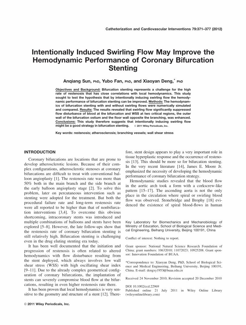
Fig. 4. Velocity contours on the middle plane at the bifurcation under different inlet flowconditions, showing a low velocity flow area near the branching ostium, which is graduallyrestricted along with swirling flow strength (From condition A to E). [Color figure can beviewed in the online issue, which is available at wileyonlinelibrary.com.]
374 Sun et al.
Catheterization and Cardiovascular Interventions DOI 10.1002/ccd.Published on behalf of The Society for Cardiovascular Angiography and Interventions (SCAI).

Velocity Distribution
Figure 4 shows contours of velocity on the middleplane of the bifurcation stenting model. There exists aflow area with very low velocity near the branchingostium. But this low velocity area is gradually restrictedalong with swirling flow strength (from condition A to E).
WSS Distribution
Figure 5 shows the distribution of WSS under differ-ent inlet flow conditions. Under the normal flow condi-tion (Condition A), WSS along the outer wall of thebifurcation is relatively low especially at the ostium ofthe bifurcation (Face 2) and at the distal region of the
stent circle strut (Face 3). Another area with lowWSS is along the floor wall opposite the bifurcationbranching (Face 1). Under conditions B to E(swirling flow conditions), the distribution of WSS isaltered by the swirling motion of the flow. In thesecases, WSS in the two critical regions (Faces 1 and2) is enhanced.
Figure 6 gives the comparison of area-weighted av-erage wall shear stress (WSS) in the three criticalregions (Faces 1,2,3) under different inlet flow condi-tions. As evident from Fig. 6, with the increase ofswirling flow strength, WSS on Face 1 and Face 2increases correspondingly, while on Face 3 WSSremains almost constant.
Fig. 5. Contours of WSS in the bifurcation under different inlet flow conditions. Under swirl-ing flow condition, WSS along the floor wall opposite the branching and the outer wall of thebranching artery is enhanced. [Color figure can be viewed in the online issue, which is avail-able at wileyonlinelibrary.com.]
Hemodynamics of Bifurcation Stenting 375
Catheterization and Cardiovascular Interventions DOI 10.1002/ccd.Published on behalf of The Society for Cardiovascular Angiography and Interventions (SCAI).

DISCUSSION
The first batch of reports on the treatment of coronarybifurcation lesions were presented in 1991 [28]. Sincethen different approaches have been proposed and variousbifurcation stenting techniques such as ‘‘Culotte,’’‘‘Crush,’’ ‘‘Kissing,’’ and ‘‘T stenting’’ have been used inclinic [29]. In addition, dedicated bifurcation stents havebeen designed these years that can facilitate bifurcationstenting and overcome some disadvantages of the conven-tional devices [1]. Unfortunately, the results of these strat-egies were disappointing as the restenosis rate was toohigh when compared with the nonbifurcation treatment.Bifurcation stenting treatment to coronary heart diseaseremains challenging even in drug eluting era today.
The mechanism of the late restenosis is complicatedand has not been fully understood. Nevertheless, it hasbeen realized that the complex geometrical configurationof coronary bifurcations compromises the implantation ofstents in place so that blood flow in the bifurcation maybe severely disturbed. Although this is one of the mainreasons for the genesis and development of restenosis[30–32], previous bifurcation strategies hardly consideredto solve this problem along the line of improving the he-modynamic performance of the stenting due to variousdifficulties. We believe that to solve this problem, weshould start from the design of specific devices that con-sider hemodynamic performance for bifurcation stenting.
It has been believed that the swirling or spiral motionof blood flow in the human aortic arch is a typical exam-ple of ‘‘form follows function’’ in the vascular systemand hypothesized that it is the swirling blood flow thateliminates stagnation flow regions so that atheroscleroticplaques can hardly form in the area of the ascending
aorta [33]. As this kind of flow pattern has advantageousfeatures of sweeping possible depositions of atherogenicsubstances such as platelets, granulocytes and lipidsaway from the arterial wall, in recent years a fewresearch groups have proposed to make best use of it tosolve such problems as intimal hyperplasia at the distalend of arterial bypass and acute thrombus in small calibergrafts [24,34–36]. In this study, we proposed to applyswirling flow principle to bifurcation stenting in order toimprove its hemodynamic performance.
The numerical results showed that by intentionallyinducing a swirling flow at the inlet of the bifurcation,the hemodynamics of bifurcation stenting could indeedbe improved. Under a normal flow condition, thereexisted a severely disturbed flow region with the forma-tion of a large vortex and low WSS at the ostium of thebranching. Another low WSS region located at the floorwall of the main artery opposite the branching ostium.Under swirling flow conditions, the flow became morestable and the vortex was restricted to a very smallarea. The stronger the swirling flow strength, thesmaller the vortex. Benefiting from the stabilization ofthe flow, WSS in the two critical regions (Faces 1 and2) was obviously enhanced. We believe that theenhancement of WSS resulting from the swirling flowcould effectively suppress the initiation and progressionof restenosis after stenting.
Here, it should be mentioned that the inlet swirlingflow has little effect on WSS in the region of Face 3. Thismay attribute to the attenuation of the swirling flow
strength along the distance from the inlet. The attenuationof the swirling flow strength can severely compromise itsbeneficial effect on the hemodynamic performance ofbifurcation stenting. Therefore, the key issue for solvingthe restenosis problem for bifurcation stenting may relyon the design of a swirling flow inducer that can provide astrong swirling flow so that the swirling strength canremain strong enough within the stent.
On the basis of this study, we could therefore sug-
gest a new bifurcation stenting strategy: After a con-
ventional bifurcation stenting, a swirling flow guider
should be positioning proximally to the coronary bifur-
cation to induce swirling flow. The swirling flow
guider could be a stent that has helical geometry fea-
tures as proposed by Seo et al [11].
CONCLUSION
In conclusion, as a preliminary study, the presentnumerical simulation theoretically substantiated ourhypothesis and provided us with useful informationfor treatment strategies for coronary bifurcationstenting.
Fig. 6. Average wall shear stress (WSS) in the three criticalregions (Face 1,2,3) under different conditions.WSS ¼ 1
A
RWSSdA, where A is the area of the surface. WSS on
Face-1 and Face-2 increases significantly along with the strengthof swirling flow, while WSS on Face-3 remains almost constant.
376 Sun et al.
Catheterization and Cardiovascular Interventions DOI 10.1002/ccd.Published on behalf of The Society for Cardiovascular Angiography and Interventions (SCAI).

REFERENCES
1. Sharma SK, Sweeny J, Kini AS. Coronary bifurcation lesions:
A current update. Cardiol Clin 2010;28:55–70.
2. Williams DO, Abbott JD. Bifurcation intervention: Is it crush
time yet? JACC 2005;64:621–624.
3. Louvard Y, Thomas M, Dzavik V, Hildick-Smith D, Galassi
AR, Pan M, Burzotta F, Zelizko M, Dudek D, Ludman P, Shei-
ban I, Lassen JF, Darremont O, Kastrati A, Ludwig J, Iakovou
I, Brunel P, Lansky A, Meerkin D, Legrand V, Medina A, Lefe-
vre T. Classification of coronary artery bifurcation lesions and
treatments: Time for a consensus! Catheter Cardiovasc Interv
2008;71:175–183.
4. Pan M, Suarez de Lezo J, Medina A, Romero M, Hernandez E,
Segura J, Castroviejo JR, Pavlovic D, Melian F, Ramırez A,
Castillo JC. Simple and complex stent strategies for bifurcated
coronary arterial stenosis involving the side branch origin. Am J
Cardiol 1999;83:1320–1325.
5. Khoja A, Ozbek C, Bay W, Heisel A. Trouser-like stenting: A
new technique for bifurcation lesions. Cathet Cardiovasc Diagn
1997;41:192–196.
6. Kobayashi Y, Colombo A, Akiyama T, Reimers B, Martini G,
di Mario C. Modified ‘‘T’’ stenting: A technique for kissing
stents in bifurcational coronary lesion. Cathet Cardiovasc Diagn
1998;43:323–326.
7. Yamashita T, Nishida T, Adamian MG, Briguori C, Vaghetti
M, Corvaja N, Albiero R, Finci L, Di Mario C, Tobis JM,
Colombo A. Bifurcation lesions: Two stents versus one stent-
immediate and follow-up results. J Am Coll Cardiol
2000;32:1145–1151.
8. Lefevre T, Louvard Y, Morice MC, Loubeyre C, Piechaud JF,
Dumas P. Stenting of bifurcation lesions: A rational approach. J
Interv Cardiol 2001;14:573–585.
9. Thury A, Wentzel JJ, Vinke RV, Gijsen FJ, Schuurbiers JC,
Krams R, de Feyter PJ, Serruys PW, Slager CJ. Focal in-stent
restenosis near step-up: Roles of low and oscillating shear
stress. Circulation 2002;105:e185–e187.
10. LaDisa JF Jr, Olson LE, Guler I, Hettrick DA, Kersten JR,
Warltier DC, Pagel PS. Circumferential vascular deformation
after stent implantation alters WSS evaluated with time-depend-
ent 3D computational fluid dynamics models. J Appl Physiol
2005;98:947–957.
11. Seo T, Schachter LG, Barakat AI. Computational study of fluid
mechanical disturbance induced by endovascular stents. Ann
Biomed Eng 2005;33:444–456.
12. Berry JL, Santamarina A, Moore JE Jr, Roychowdhury S,
Routh WD. Experimental and computational flow evaluation of
coronary stents. Ann Biomed Eng 2000;28:386–398.
13. Kastrati A, Mehilli J, Dirschinger J, Pache J, Ulm K, Schuhlen
H, Seyfarth M, Schmitt C, Blasini R, Neumann FJ, Schomig A.
Restenosis after coronary placement of various stent types. Am
J Cardiol 2001;87:34–39.
14. Moore JE Jr, Timmins LH, LaDisa JF Jr. Coronary artery
bifurcation biomechanics and implications for interventional
strategies. Catheter Cardiovasc Interv 2010;76:836–843.
15. Kilner PJ, Yang GZ, Mohiaddin RH, Firmin DN, Longmore
DB. Helical and retrograde secondary flow patterns in the aortic
arch studied by three-directional magnetic resonance velocity
mapping. Circulation 1993;88:2235–2247.
16. Stonebridge PA, Hoskins PR, Allan PL, Belch JFF. Spiral lami-
nar flow in vivo. Clin Sci 1996;91:17–21.
17. Uchida Y, Tomaru T, Nakamura F, Furuse A, Fujimori Y,
Hasegawa K. Percutaneous coronary angioscopy in patients
with ischemic heart disease. Am Heart J 1987;114:1216–1222.
18. Stonebridge PA, Brophy CM. Spiral laminar flow in arteries?
Lancet 1991;338:1360–1360.
19. Hung TH. Pulsating spiral blood flow in curved arteries. In:
Cardiovascular Science and Technology, Basic and Applied.
Louisville, KY: Oxymoron Press; 1989. pp 124–126.
20. Karino T, Goldsmith HL, Motomiya M, Mabuchi S, Sohara Y.
Flow patterns in vessels of simple and complex geometries.
Ann NY Acad Sci 1987;516:468–483.
21. Segadal L, Matre K. Blood velocity distribution in the human
ascending aorta. Circulation 1987;76:90–100.
22. Frazin LJ, Vonesh MJ, Chandran KB, Shipkowitz T, Yaacoub
AS, McPherson DD. Confirmation and initial documentation of
thoracic and abdominal aortic helical flow: An ultrasound study.
ASAIO J 1996;42:951–956.
23. Caro CG, Cheshire NJ, Watkins N. Preliminary comparative
study of small amplitude helical and conentional ePTFE arterio-
venous shunts in pigs. J R Soc Interface 2005;2:261–266.
24. Ofili EO, Kern MJ, St Vrain JA, Donohue TJ, Bach R, al-
Joundi B, Aguirre FV, Castello R, Labovitz AJ. Differential
characterization of blood flow, velocity, and vascular resistance
between proximal and distal normal epicardial human coronary
arteries: Analysis by intracoronary Doppler spectral flow veloc-
ity. Am Heart J 1995;130:37–46.
25. Fung YC. Biomechanics: Mechanical Properties of Living Tis-
sues, 2nd ed. New York: Springer-Verlag, 1993. 68p.
26. Ku DN. Blood flow in arteries. Annu Rev Fluid Mech
1997;29:399–434.
27. Liu X, Fan Y, Deng X. Effect of spiral flow on the transport of
oxygen in the aorta: A numerical study. Ann Biomed Eng
2010;38:917–926.
28. Schatz RA, Baim DS, Leon M, Ellis SG, Goldberg S, Hirshfeld
JW, Cleman MW, Cabin HS, Walker C, Stagg J, Stagg J. Clini-
cal experience with the Palmaz-Schatz coronary stent: Initial
results of a multicenter study. Circulation 1991;83:148–161.
29. Sharma SK, Kini AS. Coronary bifurcation lesions. Cardiol Clin
2006;24:233–246.
30. Brossollet LJ. Mechanical issues in vascular grafting: A review.
Int J Artif Organs 1992;15:579–584.
31. Salacinski HJ, Goldner S, Giudiceandrea A. The mechanical behav-
ior of vascular grafts: A review. J Biomater Appl 2001;15:241–278.
32. Zidi M, Cheref M. Mechanical analysis of a prototype of small
diameter vascular prosthesis: Numerical simulations. Comput
Biol Med 2003;33:65–75.
33. Liu X, Pu F, Fan YB, Deng XY, Li DY, Li SY. A numerical study
on the flow of blood and the transport of LDL in the human aorta:
The physiological significance of the helical flow in the aortic arch.
Am J Physiol Heart Circ Physiol 2009;297:H163–H170.
34. How TV, Fisher RK, Brennan JA, Harris PL. Swirling flow pat-
tern in a non-planar model of an interposition vein cuff anasto-
mosis. Med Eng Phys 2006;28:27–35.
35. Fan Y, Xu Z, Jiang W, Deng X, Wang K, Sun A. An S-type
bypass can improve the hemodynamics in the bypassed arteries
and suppress intimal hyperplasia along the host artery floor. J
Biomech 2008;41:2498–2505.
36. Morbiducci U, Ponzini R, Grigioni M, Redaelli A. Helical flow
as fluid dynamic signature for atherogenesis risk in aortocoro-
nary bypass. A numeric study. J Biomech 2007;40:519–534.
Hemodynamics of Bifurcation Stenting 377
Catheterization and Cardiovascular Interventions DOI 10.1002/ccd.Published on behalf of The Society for Cardiovascular Angiography and Interventions (SCAI).