interacting viscous instabilities in microfluidic...
TRANSCRIPT

Dynamic Article LinksC<Soft Matter
Cite this: Soft Matter, 2012, 8, 10573
www.rsc.org/softmatter REVIEW
View Article Online / Journal Homepage / Table of Contents for this issue
Interacting viscous instabilities in mic
rofluidic systemsThomas Cubaud*a and Thomas G. Mason*b
Received 18th April 2012, Accepted 18th June 2012
DOI: 10.1039/c2sm25902h
We discuss the formation, evolution, and stability of microfluidic flows involving two or more miscible
fluids that have different viscosities. When two liquids that have widely different viscosities are injected
into a rigid microfluidic device, their flow streams can naturally rearrange to form lubricated threads or
stratified flows depending on the geometry and history of injection. An overview of two-fluid and three-
fluid flow configurations in microchannels having square cross-sections is given for a variety of
injection geometries. Miscible viscous fluid threads in confined microsystems can experience a range of
viscous instabilities, such as folding and swirling. We show that microfluidics can be used to cause two
or more instabilities to interact and co-evolve in diverging microchannels, thereby creating a variety of
complex flow patterns.
1. Introduction
Beyond advancing the miniaturization of biotechnologies
through lab-on-a-chip applications, microfluidic devices provide
versatile and powerful platforms for studying basic aspects of
fluid mechanics and rheology. Simple versions of microfluidic
systems have been used for many decades in probing and
exploring a variety of complex fluids and multiphase flows.
Examples of small-scale flow geometries include thin-gap
parallel-plate Hele-Shaw cells,1 interaction chambers in hard
microfluidic homogenizers,2 thin-gap Couette shear cells,3–6 and
capillary tubes having various shapes and sizes.7–9
Thomas Cubaud
Thomas Cubaud is an Assistant
Professor of Mechanical Engi-
neering at Stony Brook Univer-
sity. He received his Ph.D. from
Paris-Sud University for his
research at ESPCI, France, and
he worked at UCLA as a post-
doctoral research scientist. Dr
Cubaud is the recipient of an
NSF CAREER Award and
three Gallery of Fluid Motion
Awards from the American
Physical Society, Division of
Fluid Dynamics.
aDepartment of Mechanical Engineering, Stony Brook University, NewYork, 11794, USA. E-mail: [email protected] of Chemistry and Biochemistry, Department of Physics andAstronomy, University of California, Los Angeles, California 90095,USA. E-mail: [email protected]
This journal is ª The Royal Society of Chemistry 2012
More recently, microfluidic devices have increasingly har-
nessed the power of lithography,10 yielding control over multiple
fluid injections and complex flow geometries. These develop-
ments have enabled the fabrication of integrated biochemical
sensors11,12 and a range of actuators, such as valves, heating
elements, and electrical conductors for manipulating electroki-
netic effects.13,14 Custom designed microfluidic cell geometries
that provide optical access, when used in combination with high-
speed microscopic imaging technology and digital control of
fluid flows, yield new control over driving stresses and insight
into highly complex flows in the absence of significant gravita-
tional effects and from low to moderate Reynolds numbers, Re.
Microfluidics can be used to create a variety of fluid instabil-
ities in a controlled manner. Interactions of flowing complex
fluids within solid microgeometries yield intriguing effects such
as structural rearrangements of aqueous foams,15–17 breakup and
coalescence of droplets,18–23 and the formation of multiple
emulsions and compound drops.24–26 In addition to producing
Thomas G: Mason
Thomas G.Mason is a Professor
of Physical Chemistry and a
Professor of Physics at UCLA.
The inventor of probe-based
thermal ‘‘passive’’ micro-
rheology, Mason pursues
research in structure–dynamics–
flow relationships and novel
forms of soft matter. He is a
fellow of the American Physical
Society, has received an NSF
CAREER Award, and shares
two Gallery of Fluid Motion
Awards with Prof. Cubaud.
Soft Matter, 2012, 8, 10573–10582 | 10573

View Article Online
some of the classic instabilities that occur between two fluids in
bounded systems, such as viscous fingering (i.e., Saffman–Tay-
lor)27–31 and capillary (i.e., Rayleigh–Plateau)32–34 instabilities,
microdevices have provided insight into elastic instabilities35–40
for non-Newtonian fluids at low Re, and inertial instabilities41–43
for moderate Re. Among the experimental challenges that exist
in the area of soft matter microfluidics, perhaps the most
important ones are: developing advanced and efficient litho-
graphic techniques that facilitate the construction of 3D micro-
channels, fabricating robust microdevices that can withstand
large injection pressures for handling highly viscous fluids, and
devising methods for rapidly mixing viscous materials at the
small scale.
The flow of miscible fluid streams having similar viscosities has
been studied in microfluidics for the formation of transverse and
longitudinal diffusion gradients.44–46 A useful technique for
manipulating fluids consists in hydrodynamically focusing a
sample stream using sheath flows.47 The initial size and spread of
parallel streams have been experimentally and theoretically
examined for a variety of channel designs and flow rates.48–52
Mixing two different streams at the small-scale is rather chal-
lenging since it typically occurs through the relatively slow
process of diffusion. This situation is in contrast with large-scale
systems that rely on turbulence to blend fluids. To circumvent
this limitation, two main types of microsystems have been
developed: (a) active micromixers, which involve additional
energy sources or moving parts, and (b) passive micromixers,
which rely on flow properties and microgeometries.53 In general,
the objectives of micromixers are to increase the interfacial area
between fluids to reduce the diffusional path and to exploit the
concept of chaotic advection54 while minimizing both the fluid
residence time and the device dimensions. Mixing thicker soft
materials with thinner solvents (i.e. fluids having a large viscosity
contrast) in microchannels is very complex because the local
viscosity evolves as fluids mix and propagate through the
microchannel network, and only a few methods – including
acoustically induced bubbles,55 splitting-and-recombination
processes,56 and viscous folding instabilities57 – have been
investigated to date.
In this article, we provide a perspective on the use of micro-
fluidic technology for generating and studying interacting
viscous instabilities, focusing on miscible and Newtonian fluids
having large viscosity contrasts and flowing at low Re # O(1).
We show how the concept of self-lubrication58–60 between
differing-viscosity fluids can be utilized in microchannels to form
single or multiple threads of more viscous liquids that are
lubricated by less viscous liquids which co-flow and envelop the
threads. This typical core-annular flow configuration facilitates
both transport and manipulation of high-viscosity fluids at the
small scale. Using the superposition principle of low Reynolds
numbers flows, we show that threads can be used to build a
variety of 3D fluid arrangements within quasi-2Dmicrochannels.
Depending on material properties, injection geometries, and
rates, these threads and stratified flows then can undergo
different types of instabilities that can be used to increase the
fluid–fluid interfacial area, thereby reducing the diffusional path
and facilitating mixing.
Viscous fluids in slender geometries that impinge on surfaces
are known to buckle through viscous folding and coiling
10574 | Soft Matter, 2012, 8, 10573–10582
instabilities.61–63 Such viscous instabilities result from both the
large viscosity coefficients of fluids and their structural configu-
rations, and can be produced at low Re in microchannels
between miscible Newtonian fluids (i.e., in the absence of inter-
facial tension). Therefore, these viscous instabilities are different
than the elastic, inertial, and capillary instabilities previously
mentioned. We illustrate the complex pattern formation
accompanying viscous instabilities through a series of experi-
mental results involving miscible Newtonian silicone oils injected
into hard silicon–glass microfluidic devices.
When two fluids are considered, we discuss the folding insta-
bility caused by the deceleration of a viscous thread surrounded
by thin miscible fluid in a diverging slit microchannel. The
folding instability can undergo a period doubling route to
chaotic folding.57 Ultimately, through a combination of
convection and diffusion, the liquids intermix and the observed
folding pattern, due to the optical refractive index difference
between the liquids, disappears further downstream. In a
different scenario, exploiting the laminar properties of micro-
flows, a viscous thread is formed in a manner that enables control
over the distance between the thread and the sidewall of a
microchannel that has a square cross-section. As the thread
begins to approach the sidewall, the gradient in velocity within
the outer less viscous oil exerts a torque on the thread, causing it
to undergo a ‘‘swirling’’ instability.64
When three miscible fluids are injected and flow co-currently
from a channel having a square cross-section to a diverging
channel, the number and complexity of flow patterns formed
become quite high. We show that several types of hydrodynamic
instabilities can be forced to occur, interact, and compete
simultaneously. For instance, three different miscible liquids can
be fed into a set of two cross-channels in series, and by
controlling the various injection points, viscosities, and flow
rates, different complex patterns, involving combinations of self-
lubrication, folding, swirling, and fingering instabilities, emerge.
We demonstrate that it is possible to form viscous fingers using
steady fluid injections of fully miscible fluids; yet, these fingers
are superimposed on a more complex flow pattern. Thus, some
patterns we report are reminiscent of the classic Saffman–Taylor
instability that occurs when a less viscous fluid displaces a more
viscous fluid at rest. However, in the more complex microfluidic
geometries that we have explored, coupling between time-
dependent and space-dependent complex fluid flows and viscous
material properties can lead to two or more interacting insta-
bilities. The resulting dynamical patterns that form are both
complex and interesting, and can provide a wealth of informa-
tion about the interplay and evolution of viscous fluid instabil-
ities in microfluidic systems.
2. Experimental methods
To produce and examine small-scale multi-fluid flows involving
two or more highly viscous liquids, it is desirable to avoid
problems that can occur when injecting these liquids into soft
microfluidic devices (e.g. unwanted deformation and separation
of sandwich layers caused by high injection pressures). By
contrast, hard microfluidic modules, made of silicon and glass,
provide robust resistance to high injection pressures, while
ensuring good optical access, and are therefore preferred.
This journal is ª The Royal Society of Chemistry 2012

Fig. 1 Schematics of symmetrical injection devices for the formation of
multi-fluid flows in square-cross-section microchannel connected to a
diverging channel of angle a. A slit channel and an outlet port further
downstream, well beyond the diverging channel region, is not shown. (a)
Dual hydrodynamic focusing sections in series. The length of the square
channels between section is not to scale (three injection ports, a ¼ 45�).(b) Simultaneous injection scheme in a ‘‘spider-type’’ connection (four
injection ports, a ¼ 15�).
View Article Online
Silicon-based nanofabrication techniques offer the possibility to
construct non-deformable microchannels, which are used to
perform precise measurements and obtain quantitative data.
Double-side polished silicon layers are deep-reactive-ion-etched
through their entire thickness (h ¼ 100 mm) to form the micro-
channel sidewalls. The top and bottom walls are two glass plates,
and these are anodically bonded to the etched silicon piece to
fully seal the duct. A collimated light source is placed on one side
of the device and flows are monitored with a high-speed camera
through a high-magnification lens having a very long working
distance that is located on the other side of the channel. This
optical method visualizes flows using transmitted light in bright
field and overall enables the imaging of curved miscible fluid
interfaces (where there is a significant difference in refractive
index) in the absence of added dye. The test fluids consist of pure
silicone oils (poly-dimethylsiloxane or PDMS) having different
molecular weights. Such simple liquids are practical because a
change in viscosity does not significantly affect other properties,
such as surface tension. According to the Stokes–Einstein rela-
tion,65 the molecular diffusivity, however, is affected by the
molecular weight and low-viscosity oils are strongly diffusive
with respect to their high-molecular weight counterparts.66
Fluids are injected into the device and steady flow rates are
controlled using several independent syringe pumps.
The microgeometries of the hard microfluidic devices are
designed to create structured and stable viscous flows near the
injection region; these flows can then be destabilized in inter-
esting ways further downstream from the injection region. In
particular, we focus on basic micro-duct geometries having
symmetric injection ports, including: (1) parallel flows with
straight channels, which are either compact (square in cross-
section) or planar (high aspect ratio Hele-Shaw cell with side-
walls), and (2) extensional flows (such as diverging and
converging sections). Fluids are injected using various symmetric
hydrodynamic focusing sections connected to a square channel
discharging to a diverging channel characterized by a divergence
angle a [Fig. 1]. Low Re flows (i.e., creeping or Stoke flows)
typically have a very small entrance length,67 and the superpo-
sition principle for different velocity fields is evident.68 Here, we
are primarily interested in flow regimes that occur for steady fluid
injections (i.e., constant flow rates) into constrained micro-
geometries. In particular, we describe miscible multi-fluid flows
having either a ‘‘sequential’’ fluid injection scheme (i.e., injection
via cross-channels in series) with three injection ports [Fig. 1(a)]
or a simultaneous fluid injection scheme with four injection ports
to minimize the device footprint [Fig. 1(b)]. Ports and liquids are
indexed symmetrically from the center of the channel outward.
Compared to a single microfluidic focusing section, ‘‘port 1’’
corresponds to the central channel where the liquid L1 of
dynamic viscosity h1 is injected at a volumetric flow rate Q1,
‘‘port 2’’ corresponds to the side-channels where liquid L2 of
viscosity h2 is injected with the total flow rate Q2. The same
index-labeling rule applies for additional liquids and ports.
These devices permit the permutation of injection of lower and
higher viscosity liquids at controlled rates into the various
injection ports, in a systematic and symmetric fashion, enabling
the exploration of morphology and stability of multi-fluid flows
as a function of initial conditions (i.e., injection order). A
particularly attractive feature of highly viscous multiphase flows
This journal is ª The Royal Society of Chemistry 2012
is the possibility of initiating self-lubrication flow phenomena to
build elaborate 3D fluid configurations using simple 2D designs,
which are more suitable for standard lithographic methods that
only require a minimal technical overhead (i.e., because fluid
injections normal to the plane of the device are not necessary).
Optical imaging is performed using a fast digital camera, and 2D
movies of the evolving pattern formation resulting from isolated
or interacting instabilities are recorded before the miscible liquids
completely intermix. Although the complex 3D viscosity and
velocity fields associated with the unstable flows within the
microgeometries cannot be deconvolved from simple 2D movies,
the contrast in refractive index of the different liquids prior to full
intermixing provides a high level of insight into the flow fields
arising from the instabilities.
3. Two-fluid flow instabilities
3.1. Propagating fluid arrangements in a square channel
Depending upon the details of the injection geometry, the fluids
chosen for each port, and the injection rates, it is possible for
lower-viscosity liquids to fully encapsulate higher-viscosity
liquids. Indeed,microflowsmade of parallel layers of fluids having
significantly different viscosities tend to self-organize into flow
structures that minimize dissipation. Lower-viscosity fluid
components tend to migrate into regions having higher shear
stresses, i.e., near the solidwalls; whereas, thicker, higher-viscosity
fluid components tend to migrate into regions having lower shear
stresses, i.e., near the channel axis. This yields the formation of
self-lubricated threads of higher-viscosity fluids surrounded by co-
flowing lower viscosity fluids. This phenomenon, however,
depends on the initial conditions (i.e., injection scheme, geometry,
and rates and also upstream flow history). In practice, although
microchannels have finite lengths, useful flow arrangements, such
as threads or other stratified flows, can still be produced over short
Soft Matter, 2012, 8, 10573–10582 | 10575

View Article Online
propagation distances from the injection region. In the following,
we examine the flow morphology in the ‘‘square channel’’ region,
which lies downstream from the injection region, yet upstream
from the diverging channel region [Fig. 1].
We turn our attention to the formation of two-fluid flows in a
square channel of height h using a variety of symmetric injection
ports. The most elementary configuration corresponds to a single
focusing section with only two liquids, one being higher-
viscosity, or ‘‘viscous’’ (V), and the other being lower-viscosity,
or ‘‘fluid’’ (F) [Fig. 2(a) and (b)]. When the thicker fluid V is
injected in the central channel and the less viscous fluid F is
introduced in the side-channels, we observe the formation of a
single viscous thread of diameter 3 lubricated by the less viscous
fluid [Fig. 2(a)]. Using both miscible and immiscible Newtonian
fluid pairs,34,69 this regime occurs for relatively large viscosity
contrasts c ¼ h1/h2 ¼ hV/hF > 15. Optical measurements of the
central stream width 3 show good agreement with the asymptotic
solution 3/h¼ (4/2)1/2, where the flow rate ratio is 4¼Q1/Q2. This
scaling form can be analytically deduced by considering a
circular duct when c [ 1 and 3/h � 1. The absence of c in this
relationship gives evidence of the full lubrication of the viscous
thread. This regime corresponds to an asymptotic behavior
where the liquid V forms a core that undergoes plug flow (i.e. has
a flat velocity profile); this core is convected in the parabolic
Poiseuille flow of F.
The complementary situation, characterized by the fluid F
being introduced in the central channel and the fluidV injected in
the side-channels, yields a completely different scenario, since V
remains in its initial location near the walls. In this case, the
flowing liquids simply form parallel layers and the fluid F forms a
central stream of width d with the high-viscosity fluid in creeping
flow near the sidewalls. Recent experimental findings70 showed
that in square microchannels such viscous-stratified flows display
a central stream width such as d/h ¼ [1 + (4c1/2)�1]�1. This
Fig. 2 Basic configurations of two co-flowing fluids in square micro-
channels, beyond the injection region. Schematics are cross-sectional
views of 3D fluid compositions (V: higher viscosity, F: lower viscosity),
propagating normal to the page in square microchannels, hypothesized
from 2D experimental images taken from the top (i.e. perpendicular to
the flow direction). In (a)–(f), top and side boundaries of squares are glass
and silicon, respectively. Two ports: (a) lubricated thread, (b) viscosity-
stratified flow. Three ports: (c) lubricated thread in the central stream of a
viscosity-stratified flow (predicted, not inferred from observations), (d)
two lubricated threads. Four ports: (e) three lubricated threads, (f) two
lubricated threads in the central stream of a viscosity-stratified flow
(predicted, not inferred from observations).
10576 | Soft Matter, 2012, 8, 10573–10582
empirical relationship is deduced from the solution of the Stokes
equation in a Hele-Shaw geometry with a flat interfacial region:66
d/h ¼ [1 + (4c)�1]�1. In square channels, however, the stress
condition at the fluid interface must be modified similar to the 2D
free-shear layer problem of parallel streams of different viscosi-
ties,71 and experiments have shown that d scales with 4c1/2 in
square channels while d scales with 4c in plane channels. Self-
lubrication effects also yield an interfacial curvature as the less
viscous fluid tend to occupy the high-shear region near the top
and bottom walls [Fig. 2(b)]. The dependence of stream widths
on fluid viscosities is useful for the development of miniature
viscometers.72
Using three and four injection ports with only two different
miscible fluids provides a means of building elaborate fluid
structures. The two basic flow configurations previously dis-
cussed can serve as a guide to test other possibilities and
manipulate fluid arrangements at the microscale. For instance,
the configuration ‘‘VFV’’ is expected to give a single thread with
viscous strata at the walls and configuration ‘‘FVF’’ yields two
threads [Fig. 2(c) and (d)]. Four injection ports form more
complex patterns with either three threads [Fig. 2(e)] or two
threads flowing in the central stream of a stratified flow
[Fig. 2(f)]. The configurations associated with two and three
threads have been tested experimentally using both sequential
and simultaneous injection scheme. Using a mass conservation
argument,64 it has been deduced that a thread propagating off-
center does not have a circular cross-section; instead, the thread
has an ellipsoidal cross-section due to the velocity field in a
square channel. In general, the observed thread widths are in
good accord with the thread-forming principle when applied to a
symmetric injection scheme at the small scale.
3.2. Instabilities of viscous threads
The lubricated thread configuration offers the advantages of
controlling both the residence time and the interfacial area of
streams of higher viscosity materials surrounded by co-flowing
streams of low-viscosity ‘‘solvents’’ simply by adjusting the
injection flow rates. A thread that is well aligned with the axis of
a compact and straight microchannel is relatively robust and
does not experience significant destabilizing stresses. However, in
other cases, viscous instabilities occur. We have identified two
basic instabilities for threads, namely (1) a folding instability57
that results when threads are subject to a compressive stress and
deceleration along the flow direction in a diverging channel, and
(2) a viscous swirling instability that results when a thread is
significantly sheared in a velocity gradient of the less viscous
fluid, i.e., near the channel’s side-walls.64
3.2.1. Diverging flows: thread folding. Diverging slit micro-
channels constitute basic microfluidic designs and are important
for scaling up processes (e.g., for recovering soft materials from
microchannels). In extensional flows, the convective acceleration
in the Navier–Stokes equation is non negligible, and dynamic
stresses are exerted on fluid structures. For instance, a droplet
typically elongates along the flow direction in a converging
channel and deforms normal to the main flow direction in a
diverging channel.73 Similarly, continuous slender structures
deform in extensional flow fields and lubricated threads are
This journal is ª The Royal Society of Chemistry 2012

View Article Online
observed to buckle in diverging channels [Fig. 3]. For moderate
viscosity contrasts, a thread simply enlarges (i.e. expands its
diameter) along the diverging flow direction, whereas for very
large c, the thread’s thickness remains essentially constant along
the flow direction, and the thread buckles rather than dilates.74
The folding frequency is linearly related to the injection flow rate
in the folding regime for large threads.57 Diverging channels also
form an effective transition zone between compact channels,
which facilitate thread lubrication, and planar channels, which
favors viscosity-stratified flows. As a result, threads can experi-
ence a non-linear lubrication failure in the diverging channel.75
The folding instability also occurs for multiple threads. To
examine the crossover between single andmultiple thread folding,
we progressively increase Q1 to observe the transition from a
single thread to two threads [Fig. 3(a)–(c)]. In the two-thread case,
the fact that filaments are lubricated allows for manipulating their
distance with the virtual interface between Q1 and Q3, which
follows the relationship d/h ¼ [1 + (Q1/Q3)�1]�1 since the viscosity
ratio between L1 and L3 is unity. For small d, the two threads are
observed to phase-lock, i.e., they fold in tandem. Fig. 3(d) shows
the formation and folding of threads using the channel design
shown in Fig. 1(b). Overall, the folding instability increases the
threads’ surface areas, thereby facilitating faster intermixing of
higher and lower viscosity liquids downstream.
3.2.2. Off-center threads in velocity gradients: swirling insta-
bility. Another basic viscous thread instability occurs in straight
channels for lubricated filaments located near the solid walls.
While exploring the range of parameters for two threads in a
square channel, we observed the development of a shear-induced
instability64 for large thread separations d and small thread
Fig. 3 Methods for creating single and multiple threads of a higher
viscosity liquid, surrounded by a lower-viscosity liquid, that fold as they
co-flow into diverging channels. The viscosity contrast between the low-
and the high-viscosity fluids is c¼ 83, flow rates are in ml min�1. (a) Single
folding for two ports, Q1 ¼ 5, Q2 ¼ 13 (adapted from ref. 57). (b) Two
threads in close proximity fold in tandem (i.e. strongly phase-locked),
Q1 ¼ 5, Q2 ¼ 1, Q3 ¼ 10. (c) Two well-separated threads folding, Q1 ¼ 5,
Q2 ¼ 5, Q3 ¼ 10 (adapted from ref. 64). (c) Formation of three well-
separated threads by a spider-type injection that fold in the diverging
region, Q1 ¼ 1, Q2 ¼ 20, Q3 ¼ 2, Q4 ¼ 20 (adapted from ref. 69).
This journal is ª The Royal Society of Chemistry 2012
thickness 3. To represent the flow destabilization process, the
velocity field of the less viscous fluid F is displayed in Fig. 4(a). In
the high-shear region (i.e., near the side-walls), the velocity
differential on either side of the thread destabilizes its slender
viscous structure over time and distance [Fig. 4(b)], yielding an
evolving pattern that is reminiscent of the Kelvin–Helmholtz
instability of a single planar interface. Although the deformation
process is continuous, four basic steps are identified with (a) the
development of the most dominant wavelength l along the
thread, (b) the local accumulation of viscous fluid in ‘‘bulbs’’, (c)
the thinning of the tails connecting bulbs, and (d) the detachment
of bulbs from their neighbors to form independent viscous swirls.
As expected for finite objects in a shear flow, swirls rotate during
advection and can also pair up. Here, small Reynolds numbers
have been investigated, and there is no significant drift in the low
shear region.
Using a single fluid pair having large viscosity contrast hV/hF¼83, we have shown that the mean wavelength of destabilization l
normalized by the thread diameter 3 is inversely proportional to
the thread separation d according to l/3 z 2.3/d. We have
devised a simple scaling model for predicting this behavior based
on the viscous-elastic analogy.76 Experiments involving a single
thread aligned off-centered from the channel axis show a similar
shear-induced swirling instability.69 This regime is important,
since it enables the formation of discrete fluid elements (i.e.,
ephemeral swirls reminiscent of droplets) using miscible fluids in
a continuous flow configuration.
4. Three-fluid flow instabilities
4.1. Propagating fluid arrangements in a square channel
In this section, we examine the multi-fluid flow configurations for
a system composed of three miscible Newtonian fluids, one being
Fig. 4 Swirling instability of two miscible threads in a straight, square-
cross-section microchannel, downstream from the injection region. (a)
Schematic of the main velocity profile U in the channel middle plane
(lower part). Two lubricated threads (purple) near the channel axis
remain relatively stable to shear-induced perturbations, but experience
flow-induced torques due to the velocity gradient in the lower-viscosity
liquid (light green). Hypothesized cross-sectional view of the square
microchannel having two off-center threads, just after formation, prior to
the development of the swirling instability further downstream (upper
part). (b) Optical microscopic observations of the development of the
viscous swirling instability for a miscible thread near the channel side-
walls, three injection ports, viscosity contrast c ¼ hV/hF ¼ 83, flow rates
in ml min�1: Q1 ¼ 20, Q2 ¼ 3, Q3 ¼ 20. Images shown are closer to the
injection region (top) and further downstream (bottom) where the growth
of the instability causes the formation of uniform swirls (adapted from
ref. 64).
Soft Matter, 2012, 8, 10573–10582 | 10577
View Article Online
very viscous (V), one being moderately viscous (M), and one
being less viscous, i.e. fluid (F). Given the large number of
potential injection scenarios, we restrict our discussion to a
sequential fluid injection involving three ports [Fig. 1(a)]. As
fluids and injection ports are distinguishable, their permutation
leads to the six basic configurations displayed in Fig. 5. These
configurations, labeled from (a) to (f), are hypothesized from the
encapsulation mechanisms observed in two-fluid systems using
the superposition principle of creeping flows.
In the two first configurations, (a) and (b), F is injected near the
sidewalls, which leads to the formation of compound threads
having either a highly-viscous core wrapped by M, which in turn
is enveloped by F [Fig. 5(a)] or a thread ofMwith threads ofV on
both sides [Fig. 5(b)]. Although, theses flow arrangements are
logically deduced from their two-fluid counterparts, their
experimental behavior in a diverging channel corroborate our
hypothesis since the configuration (a) leads to the symmetric
folding of V within a layer of M surrounded by F, and configu-
ration (b) produces the folding of the two side threads.69
Configurations (c) and (d) consist of injecting M near the side-
walls. Configuration (c) has not been experimentally examined,
but we speculate that such flow arrangement is a priori possible.
The configuration (d), where two threads are located at the
interface between F and M fluids, has been extensively investi-
gated in laboratory experiments and leads to very intriguing
dynamics that we describe as a case study in the next section.
Finally, configurations (e) and (f) occur when V is injected near
the sidewalls. Assuming that the highly viscous liquids form
effective ‘‘viscous walls’’, the proposed configurations are plau-
sible for strongly stratified flows.
4.2. Parallel flows
In a straight square microchannel involving three different
miscible fluids, the configuration shown in Fig. 5(d) displays a
wide range of different dynamical behaviors. A series of
Fig. 5 Basic steady-state flow configurations of three fluids (V: highest
viscosity, M: medium viscosity, F: lowest viscosity) in a square-cross-
section microchannel, downstream from the injection region, propa-
gating normal to the page, hypothesized from encapsulation mechanisms
based on 2D observations of simpler two-fluid flows. (a) and (b) show
different types of lubricated compound threads, (c) and (e) each show a
lubricated thread in the central stream of a viscosity-stratified flow
(predicted, not inferred from observations), (d) two threads at the
interface of a viscosity-stratified flow, (f) double viscosity-stratified flow
(predicted, not inferred from observations).
10578 | Soft Matter, 2012, 8, 10573–10582
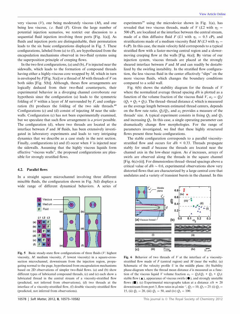
experiments77 using the microdevice shown in Fig. 1(a), has
revealed that two viscous threads, made of V (L2 with h2 ¼500 cP), are localized at the interface between the central stream,
made of a thin diffusive fluid F (L1 with h1 ¼ 0.5 cP), and
stratifications made of a medium viscosity fluidM (L3 with h3 ¼6 cP). In this case, the main velocity field corresponds to a typical
stratified flow with a faster-moving central region and a slower-
moving creeping flow at the walls [Fig. 6(a)]. By virtue of our
injection system, viscous threads are placed at the strongly
sheared interface between F and M and can readily be destabi-
lized by the swirling instability. In the stratified flow configura-
tion, the less viscous fluid in the center effectively ‘‘slips’’ on the
more viscous fluids, which changes the boundary conditions
compared to a solid wall.
Fig. 6(b) shows the stability diagram for the threads of V
where the normalized average thread spacing d/h is plotted as a
function of the volume fraction of the viscous fluid V, a2 ¼ Q2/
(Q1 +Q2 +Q3). The thread–thread distance d, which is measured
as the average length between estimated thread centers, depends
on the flow rate ratio, Q1/Q3, and a2 provides a measure of the
threads’ size. A typical experiment consists in fixing Q2 and Q3
and increasing Q1. In this case, a single operating parameter can
dramatically change flow morphologies. For the range of
parameters investigated, we find that these highly structured
flows present three basic configurations.
The stable configuration corresponds to a parallel viscosity-
stratified flow and occurs for d/h < 0.33. Threads propagate
stably for small d because the threads are located near the
channel axis in the low-shear region. As d increases, arrays of
swirls are observed along the threads in the square channel
[Fig. 6(c)-(ii)]. For dimensionless thread–thread spacings above a
critical value of d/h � 0.6, experimental observations show very
distorted flows that are characterized by a large central core that
undulates and a variety of transient bursts in the channel. In this
Fig. 6 Behavior of two threads of V at the interface of a viscosity-
stratified flow made of F (central region) and M (near the walls). (a)
Schematic of the velocity profile U in the middle plane. (b) Stability
phase-diagram where the thread mean distance d is measured as a func-
tion of the viscous liquid V volume fraction a2 ¼ Q2/(Q1 + Q2 + Q3):
stable flow (:), appearance of viscous swirls (C), and strongly unstable
flows (-). (c) Experimental micrographs taken at a distance x/h z 20
downstream from port 3, flow rates in ml min�1,Q2¼ 10,Q3¼ 25: (i)Q1¼15, (ii) Q1 ¼ 20, (iii) Q1 ¼ 50, and (iv) Q1 ¼ 100.
This journal is ª The Royal Society of Chemistry 2012

View Article Online
case the unsteady nature of this flow results from the strong
interplay between the large interfacial shearing between F andM,
and the strong development of the swirling instability near the
walls. The transition between the viscous swirl flows and highly
unstable flows is more apparent when examining the resulting
flow in a diverging channel. Overall, the flow becomes unstable
for large thread spacing d and small thread volume fraction a2,
which is essentially similar to off-center threads that experience
torques driven by velocity gradients in a single-phase flow.
4.3. Diverging flows
We next turn our attention to the flow behavior of the configu-
ration shown in Fig. 5(d) further downstream in the diverging
channel. When the inlet flow is stable (i.e., d/h < 0.33), typical
morphologies consist of a central diffusive region made of F with
asymmetrical thread folding of V in a side flow ofM [Fig. 7]. The
disparity in viscosity between F and M produces a significant
velocity difference between the fast central region and the slow
side-flow. The velocity difference between each of the sheath
flows prevents threads from folding at the V–F interface (i.e.,
inward towards the channel’s centerline) and the folding
Fig. 7 Examples of intermittent flow morphologies in the diverging
channel region for stable inlet flows fixed at Q1 ¼ 15, Q2 ¼ 10, and Q3 ¼25 in ml min�1: (a) Dendrite flow (observed: left; schematic: right), and (b)
Fishbone flow (observed: left; schematic: right). (c) Evolution of the
dimensionless wavelength l/h as a function of normalized radius r/h from
a virtual source at the end of the square microchannel: dendrite (,), solid
line fits: l/h ¼ 0.18 + 0.88(r/h)�1; fishbone (B), solid line: smoothed
values. (d) Spatial evolution of the dimensionless finger length t/h. Inset:
dimensionless length versus dimensionless wavelength (lines: smoothed
values from experimental data).
This journal is ª The Royal Society of Chemistry 2012
phenomenon remains restricted to the V–M interface (i.e.,
outward from the channel’s centerline). Although threads fold
asymmetrically with a deformation that does not propagate
completely through the fast central stream, threads remain
hydrodynamically coupled (i.e., phase-locked) and form, along
with the low-viscosity fluid, an effective structure, which regu-
larly undulates. In addition, the highly diffusive behavior of the
low-viscosity oil F tends to blur the thread interface near the
channel center and blended segments of threads resemble fingers.
The convected fingering patterns display a relatively complex
intermittent flow behavior. In particular, although the inlet
conditions are steady, we observe a feedback between the initial
thread–thread separation d in the square channel and the flow
patterns seen in the diverging channel. For a given set of
flow rates, the system displays bistability between ‘‘dendrite’’
flow regimes for larger d [Fig. 7(a)] and ‘‘fishbone’’ flow regimes
for smaller d [Fig. 7(b)]. The dendrite flow shows finger-like
protrusions that can branch along the interface between the
fluids. The fishbone flow shows an alternating arrangement of
unbranched finger-like protrusions that is linked to the alter-
nating folds of the folding instability. A large-scale buckling of
the entire structure made of V and F characterizes the transition
between regimes.
We quantitatively compare patterns by measuring the
apparent finger wavelength l and length t as a function of the
radius r from the virtual source, which is located at (x, y) ¼ (�h/
2, 0) from the junction between square and diverging channels. A
straight line is first digitally drawn between each finger node. The
center of the line defines the polar coordinates of the associated
finger (r, q), the length of the line corresponds to the finger
wavelength l, and the finger length t is the distance from the
finger apex to its coordinate [Fig. 7(a) – right]. As expected for a
source flow in a sector, the finger wavelength l is overall inversely
proportional to the distance r [Fig. 7(c)]. The finger length t is
observed to increase along the flow direction [Fig. 7(d)]. For r/h >
4, the significant scatter in data during dendrite flow results in
part from the lateral buckling of fingers that produce branched
structures. In these graphs, the general behavior is indicated with
solid trend lines that permit the average length t to be related to
the main wavelength l for both cases [see Fig. 7(d) – inset].
Experimental findings suggest a linear relationship between t and
l, which is in overall agreement with the idea of the mass
conservation in a finger experiencing a linear rate of deforma-
tion, as would be expected for a solenoidal velocity field,71 since
diffusion and compressibility effects can be neglected as a first
order approximation.
The viscous fingers that appear in the diverging channel region
(i.e. for 2 # r/h # 6) display a broad range of morphologies
depending on initial thread size, fluid viscosities, and flow rates
[Fig. 8]. Since the fingers are oriented normal to the thread’s local
flow direction, defined by the angle q, the decelerating flow field
produces an effective lateral compression of the overall structure
that can expand into multiple dendrite layers. For instance,
Fig. 8(a) shows the resulting growth of one, two, and three layers
of relatively large fingers. The flow pattern, here, suggests the
shape of a ‘‘cactus’’. During the complex buckling of the meta-
structure formed by fluids V and F, medium-sized fingers can
deform with a large aspect ratio [Fig. 8(b)]. In this case, we label
the flow morphology as ‘‘forest’’. Finally, thin threads separated
Soft Matter, 2012, 8, 10573–10582 | 10579

Fig. 8 Detailed examples of the typical evolution of viscous dendrites
from upstream to downstream regions of a diverging channel (arranged
in columns from top to bottom). Images are oriented along q, the local
flow direction. Finger growth results from convective deceleration (flow
rates are in ml min�1): (a) ‘‘Cactus’’ flows exhibiting branched dendrites
for thicker threads, Q1 ¼ 15, Q2 ¼ 10, Q3 ¼ 25. (b) ‘‘Forest’’ flows for
medium-size threads, Q1 ¼ 10, Q2 ¼ 5, Q3 ¼ 20. (c) ‘‘Cilia’’ flows for thin
threads, top image: Q1 ¼ 0.5, Q2 ¼ 5, Q3 ¼ 20; bottom two images: Q1 ¼10, Q2 ¼ 15, Q3 ¼ 55.
Fig. 9 Time-series of details of the swirls that form in a diverging
channel and propagate downstream (time between successive frames is
6.25 ms). The markers * and + identify evolution of specific swirls, flow
rates in ml min�1. (a) Marginally unstable inlet flow, Q1 ¼ 10, Q2 ¼ 5,
Q3 ¼ 20; dendrites are sheared, yielding some swirling features. (b) Well-
formed viscous swirling flows, Q1 ¼ 20, Q2 ¼ 10, Q3 ¼ 25.
View Article Online
by a small distance d can develop into compact and very large
aspect ratio arrangements than can buckle into multiple
branches. Such shapes are reminiscent of ‘‘cilia’’ [Fig. 8(c)].
In all cases, it is important to consider that the formation of
multiple layered viscous dendrites in our system results from the
asymmetrical buckling of threads. The resulting morphologies
suggest those observed during the Saffman–Taylor fingering
instability, chemically induced growth processes, and solidifica-
tion fronts. Our 2D observations do not provide a full 3D view of
the compositions of the flowing fluids in the diverging channel
region, so any interpretation of the visualized flow patterns
necessarily involves making extrapolations that are speculative.
Despite this caveat, one possible interpretation of the complex
flow patterns in Fig. 7 involves a fingering instability interacting
with a folding instability. Since the centrally injected flow is the
least viscous liquid, the visible boundaries of flow fronts
emerging from the central region in the diverging channel may
finger as the least viscous liquid is driven by the extensional flows
(roughly perpendicular to the deceleration along the flow direc-
tion) into the more viscous liquids outside. The relatively thin
thread-like regions of highest viscosity liquid provide good
refractive-index contrast as a marker for these flow fronts.
However, as the fingering penetration of the least viscous liquid
begins to occur, two threads of the largest viscosity liquid are also
folding, thereby creating a modulation of the fingering front.
This modulation is especially evident in the alternating fishbone
pattern [Fig. 7(b)]; the tendency of viscous fingers to branch in
diverging flows is more evident in the dendrite pattern [Fig. 7(a)].
Although this combination of instabilities is only one possible
interpretation, it highlights the general idea that two or more
viscous instabilities can be combined to produce interesting and
complex flow patterns in microfluidic devices. A closely related
phenomenon occurs during the folding of viscous layers in
10580 | Soft Matter, 2012, 8, 10573–10582
dissimilar media, which has been theoretically examined in the
context of structural geology.78 The presence of walls and
complex velocity fields in our case, however, prevents a direct
comparison with this case.
For effective thread distances above the critical value d/h >
0.33, arrays of viscous swirls appear along the threads in the
square inlet microchannel. In this case, swirls can compete with
the ‘‘dendrite instability’’ previously discussed in the diverging
channel. Fig. 9 shows two sets of images obtained from high-
speed movies for the cases when (a) the flow is marginally
unstable, i.e., a few swirls appears along the threads (d/h � 0.33)
and when (b) swirls are well developed along the threads (d/h �0.36). Such flows lead to very complex dynamics since viscous
swirls are not necessarily all detached from one another before
they enter the diverging channel. In both case, the decelerating
flow produce an alternate arrangement of swirls, similar to
droplets formed between immiscible liquids in diverging chan-
nels.23 Here, since the fluids are miscible, structures made of
viscous fingers and swirls become compressed along the flow
direction in the divergence and form complex diffusive archi-
tectures, which nevertheless remain distinguishable over short
time periods using bright-field microscopic imaging.
Finally, for large thread distances, d/h > 0.6, the inlet flow in
the square channel becomes rather complex and the resulting
patterns observed in the diverging channel display chaotic
behavior. In this case, the proportion of low-viscosity oil F is
large compared to M and V [i.e., a1 ¼ Q1/(Q1 + Q2 + Q3) > 0.5)
and the central stream occupies most of the diverging channel. As
a result, viscous swirls become rapidly surrounded with F, and a
wide range of ‘‘turbid’’ flow patterns is observed. Fig. 10 shows a
few examples of these structures composed of (a) assemblies of
interacting swirls that vaguely resemble van Karman vortex
streets, (b) multiple diffusive swirls joined together in complex
manifolds, and (c) viscous heterogeneous flows composed of F,
M, and V.
Overall, the formation of such highly unstable microflows
using three Newtonian fluids having different viscosities suggests
This journal is ª The Royal Society of Chemistry 2012

Fig. 10 Examples of chaotic miscible flow structures in the diverging channel region for large thread–thread separations d, flow rates in ml min�1. Three
examples are shown at each set of flow rates. (a) Q1 ¼ 50, Q2 ¼ 10, Q3 ¼ 25. (b) Q1 ¼ 100, Q2 ¼ 5, Q3 ¼ 15. (c) Q1 ¼ 200, Q2 ¼ 10, Q3 ¼ 25.
View Article Online
an analogy with hydrodynamic turbulence at large Re and elastic
turbulence at low Re. Indeed, these unstable flows are charac-
terized by highly irregular spatio-temporal structures and
enhanced mixing.79 As the term ‘‘viscous turbulence’’ however
would be extremely misleading, for clarity, we prefer the term
‘‘viscous heterogeneous flows’’ (or ‘‘viscous chaotic flows’’) owing
to the fact that many of the phenomena observed are based on
the initial flow structures and the evolution of the local viscosity
as fluid mix in the system. Here, we show that non-linear
deformation processes of miscible interfaces through folding and
swirling instability in microgeometries qualitatively enhance
mixing of Newtonian fluids at low Re. Further work is required
to quantitatively define the efficiency of mixing of differing-
viscosity miscible fluids in microfluidic systems.
5. Conclusion
In this perspective on the formation, structure, and dynamics of
miscible multiphase flows of differing-viscosity fluids in micro-
fluidics, we have emphasized how different fluid injection
scenarios and geometries can be used to produce lubricated
threads, viscosity-stratified flows, or combinations of both. The
control of lubricated threads offer a new route for manipulating
thick substances at the microscale. We have described basic
thread instabilities, including folding and swirling instabilities, as
well as more complex flow patterns that result from the inter-
action of two or more basic instabilities. Insights gained from
studies of two-fluid flows have enabled us to infer morphologies
of three-fluid flows in parallel and extensional geometries.
Moreover, for the case study of a three-fluid flow in the diverging
channel region, it is likely that the alternating undulations,
resulting from the folding instability of the two highly viscous
threads, play an important role in setting the initial conditions
for penetration of the least viscous liquid into the more viscous
liquids via a second instability – the fingering instability.
This work provides a mere glimpse into the broad and largely
unexplored realm of interacting fluid instabilities, particularly
viscous instabilities which can be readily produced in micro-
fluidic devices. In the three-fluid case, we show the existence of
specific injection scheme that leads to intricate flow behaviors. In
particular, the transition from ordered to disordered flows is
This journal is ª The Royal Society of Chemistry 2012
achieved by simply increasing the flow rate of the less viscous
central stream. The development of secondary instabilities for
three-fluid flows suggests that introducing miscible additives
having different viscosities in the appropriate flow configuration
may help achieve rapid mixing at the small scale.
Beyond creating new experiments to further explore a wide
variety of interacting fluid instabilities, many important theo-
retical challenges remain. An example of a simpler scenario
would be solving coupled time- and space-dependent non-linear
partial differential equations for the evolving velocity and
viscosity fields, which incorporate aspects of convection and
diffusion subject to boundary conditions that reflect injection
flow-rate conditions and wall surface properties. Much higher
levels of complexity in the dynamical equations of motion for the
flowing material and its local compositional changes are of
course possible. For instance, in some cases, soft materials
exhibiting non-Newtonian rheological properties over certain
ranges of compositions could dramatically alter the dynamical
pattern formation.
A complete set of rules for predicting the dominance of a given
instability over another, depending upon materials, geometry,
and flow conditions, has yet to be developed. Some instabilities
do not occur below a well-defined ‘‘critical’’ onset value of a
dimensionless parameter, based on the evolutionary equations,
whereas other instabilities do not exhibit a critical onset. Thus,
competition between different instabilities may be seen only in
certain regimes of control parameters; in other regimes, the
dominance of a particular instability may be very nearly
complete, thereby suppressing any others. Moreover, beyond
onset criteria, growth rates of two or more instabilities could be
different, and these growth rates could also play an important
role in controlling dominance of one type of instability over
another. For instance, one instability may have an earlier onset
but slower growth, thereby dominating upstream in the micro-
channel, whereas a second instability may have a larger growth
rate, thereby enabling it to out-compete and dominate over the
first instability downstream. Moreover, the first instability could
provide a modulation or envelope which affects the patterns
formed by the second instability downstream.
An important experimental challenge is obtaining fully three-
dimensional high-speed volume movies of interacting
Soft Matter, 2012, 8, 10573–10582 | 10581

View Article Online
instabilities, even as they occur in quasi-two-dimensional
‘‘sandwich’’ geometries. Although interacting instabilities can be
highly complex even for simple incompressible Newtonian
liquids, the introduction of non-Newtonian and anisotropic
liquid materials in controlled microfluidic geometries would add
yet further possibilities for tuning and altering the nature of
interacting instabilities.
References
1 L. Patterson, J. Fluid Mech., 1981, 113, 513.2 P. L. Tang, E. D. Sudol, C. A. Silebi and M. S. El-Aasser, J. Appl.Polym. Sci., 1991, 43, 1059.
3 A. Rodger, Methods Enzymol., 1993, 226, 232.4 T. G. Mason and J. Bibette, Langmuir, 1997, 13, 4600–4613.5 A. Prigent, G. Gregoire, H. Chate, O. Dauchot and W. van Saarloos,Phys. Rev. Lett., 2002, 89, 014501.
6 S. Lerouge, M. A. Fardin, M. Argentina, G. Gregoire andO. Cardoso, Soft Matter, 2008, 4, 1808–1819.
7 C. H. Barnett and W. Cochrane, Nature, 1956, 177, 740–742.8 B. Legait, J. Colloid Interface Sci., 1983, 96, 28–38.9 J. Bico and D. Quere, J. Fluid Mech., 2002, 467, 101–127.10 M. J. Madou, Fundamentals of Macrofabrication and Nanotechnology,
CRC Press, Boca Raton, FL, 2012, vol. II.11 T. H. Wang, Y. H. Peng, C. Y. Zhang, P. K. Wong and C. M. Ho,
J. Am. Chem. Soc., 2005, 127, 5354–5359.12 K. K. Liu, R. G. Wu, Y. J. Chuang, H. S. Khoo, S. H. Huang and
F. G. Tseng, Sensors, 2010, 10, 6623–6661.13 T. M. Squires and S. R. Quake, Rev. Mod. Phys., 2005, 77, 977–1026.14 N.-T. Nguyen and S. T. Wereley, Fundamentals and Applications of
Microfluidics, Artech House Inc., Norwood, 2006.15 W. Drenckhan, S. J. Cox, G. Delaney, H. Holste, D. Weaire and
N. Kern, Colloids Surf., A, 2005, 263, 52–64.16 E. Lorenceau, Y. Y. C. Sang, H. Reinhard and S. Cohen-Addad,
Phys. Fluids, 2006, 18, 097103.17 J. P. Raven and P. Marmottant, Phys. Rev. Lett., 2009, 102, 084501.18 D. R. Link, S. L. Anna, D. A. Weitz and H. A. Stone, Phys. Rev.
Lett., 2004, 92, 054503.19 L. M�en�etrier-Deremble and P. Tabeling, Phys. Rev. E: Stat.,
Nonlinear, Soft Matter Phys., 2006, 74, 035303(R).20 T. Cubaud, Phys. Rev. E: Stat., Nonlinear, Soft Matter Phys., 2009,
80, 026307.21 Y. C. Tan, Y. L. Ho and A. P. Lee, Microfluid. Nanofluid., 2007, 3,
495.22 N. Bremond, A. R. Thiam and J. Bibette, Phys. Rev. Lett., 2008, 100,
024501.23 B. M. Jose and T. Cubaud, Microfluid. Nanofluid., 2012, 12, 687.24 R. K. Shah, H. C. Shum, A. C. Rowat, D. Lee, J. J. Agresti,
A. S. Utada, L. Y. Chu, J. W. Kim, A. Fernandez-Nieves,C. J. Martinez and D. A. Weitz, Mater. Today, 2008, 11, 18.
25 N. Pannacci, H. Bruss, D. Bartolo, I. Etchart, T. Lockhart,Y. Hennequin, H. Willaime and P. Tabeling, Phys. Rev. Lett., 2008,101, 164502.
26 S. A. Khan and S. Duraiswamy, Lab Chip, 2009, 9, 1840.27 P. G. Saffman andG. Taylor, Proc. R. Soc. London, Ser. A, 1958, 245,
312.28 J. S. Langer, Science, 1989, 243, 1150–1156.29 G. M. Homsy, Annu. Rev. Fluid Mech., 1987, 19, 271–311.30 J. Nittmann, G. Daccord and H. E. Stanley, Nature, 1985, 314, 141–
144.31 E. Pitts, J. Fluid Mech., 1980, 97, 53.32 P. Garstecki, H. A. Stone and G. W. Whitesides, Phys. Rev. Lett.,
2005, 94, 164501.33 P. Guillot, A. Colin, A. S. Utada and A. Ajdari, Phys. Rev. Lett.,
2007, 99, 104502.34 T. Cubaud and T. G. Mason, Phys. Fluids, 2008, 20, 053302.35 A. Groisman, M. Enzelberger and S. R. Quake, Science, 2003, 300,
955–958.36 T. Burghelea, E. Segre, I. Bar-Joseph, A. Groisman and V. Steinberg,
Phys. Rev. E: Stat., Nonlinear, Soft Matter Phys., 2004, 69, 066305.
10582 | Soft Matter, 2012, 8, 10573–10582
37 R. J. Poole, M. A. Alves and P. J. Oliveira, Phys. Rev. Lett., 2007, 99,164503.
38 O. Bonhomme, A. Morozov, J. Leng and A. Colin, Phys. Rev. E:Stat., Nonlinear, Soft Matter Phys., 2011, 83, 065301(R).
39 J. Wang and D. F. James, J. Rheol., 2011, 55, 1103.40 C. P. Pipe and G. H. McKinley, Mech. Res. Commun., 2009, 36, 110.41 D. Di Carlo, Lab Chip, 2009, 9, 3038.42 X. Mao, J. R. Waldeisen and T. J. Huang, Lab Chip, 2007, 7, 1260.43 J. M. Martel and M. Toner, Phys. Fluids, 2012, 24, 032001.44 M. A. Holden, S. Kumar, E. T. Castellana, A. Beskok and
P. S. Cremer, Sens. Actuators, B, 2003, 92, 199–207.45 J. Goulpeau, B. Lonetti, D. Trouchet, A. Ajdari and P. Tabeling, Lab
Chip, 2007, 7, 1154–1161.46 W. Georgescu, J. Jourquin, L. Estrada, A. R. A. Anderson,
V. Quanrata and J. P. Wikswo, Lab Chip, 2008, 8, 238–244.47 J. B. Knight, A. Vishwanath, J. P. Brody and R. H. Austin, Phys. Rev.
Lett., 1998, 80, 3863–3866.48 R. F. Ismagilov, A. D. Stroock, P. J. A. Kenis, G. Whitesides and
H. A. Stone, Appl. Phys. Lett., 2000, 76, 2376.49 J. Jimenez, J. Fluid Mech., 2005, 535, 245–254.50 Z. G. Wu and N. T. Nguyen, Sens. Actuators, B, 2005, 107, 965–
974.51 G. B. Lee, C. C. Chang, S. B. Huang and R. J. Yang, J. Micromech.
Microeng., 2006, 16, 1024–1032.52 J. Dambrine, B. G�eraud and J.-B. Salmon, New J. Phys., 2009, 11,
075015.53 C. Y. Lee, C. L. Chang, Y. N. Wang and L. M. Fu, Int. J. Mol. Sci.,
2011, 12, 3263–3287.54 J. M. Ottino, Annu. Rev. Fluid Mech., 1990, 22, 207.55 S. Wang, X. Huang and C. Yang, Lab Chip, 2011, 11, 2081.56 H.M. Xia, Z. P. Wang, Y. X. koh and K. T. May, Lab Chip, 2010, 10,
1712.57 T. Cubaud and T. G. Mason, Phys. Rev. Lett., 2006, 96, 114501.58 D. D. Joseph, K. Nguyen and G. S. Beavers, J. Fluid Mech., 1984,
141, 319–345.59 D. D. Joseph and Y. Y. Renardy, Fundamentals of Two-Fluid
Dynamics. Part II: Lubricated Transport, Drops and MiscibleLiquids, Springer-Verlag, New York, 1993.
60 B. Khomami and K. C. Su, J. Non-Newtonian Fluid Mech., 2000, 91,59–84.
61 M. Skorobogatiy and L. Mahadevan, Europhys. Lett., 2000, 52, 532–538.
62 S. Chiu-Webster and J. R. Lister, J. Fluid Mech., 2006, 569, 89–111.63 N. M. Ribe, M. Habibi and D. Bonn, Annu. Rev. Fluid Mech., 2012,
44, 249.64 T. Cubaud and T. G. Mason, Phys. Rev. Lett., 2007, 98, 264501.65 F. Ould-Kaddour and D. Levesque, Phys. Rev. E: Stat. Phys.,
Plasmas, Fluids, Relat. Interdiscip. Top., 2000, 63, 011205.66 T. Cubaud and T. G. Mason, Phys. Rev. E: Stat., Nonlinear, Soft
Matter Phys., 2008, 78, 056308.67 D. J. Tritton, Physical Fluid Dynamics, Oxford University Press Inc.,
New York, 1988.68 E. Guyon, J.-P. Hulin, L. Petit and C. D. Mitescu, Physical
Hydrodynamics, Oxford University Press, New York, 2001.69 T. Cubaud and T. G. Mason, New J. Phys., 2009, 11, 075029.70 T. Cubaud, B. M. Jose, S. Darvishi and R. Sun, Int. J. Multiphase
Flow, 2012, 39, 29.71 G. K. Batchelor, An Introduction to Fluid Mechanics, Cambridge
University Press, New York, 1967.72 P. Guillot, P. Panizza, J. B. Salmon, M. Joanicot, A. Colin,
C. H. Bruneau and T. Colin, Langmuir, 2006, 22, 6438–6445.73 J. T. Cabral and S. D. Hudson, Lab Chip, 2006, 6, 427–436.74 T. Cubaud, B.M. Jose and S. Darvishi,Phys. Fluids, 2011, 23, 042002.75 S. Darvishi and T. Cubaud, J. Fluids Eng., 2011, 133, 031203.76 L. D. Landau and E. M. Lifshitz, Theory of Elasticity, Pergamon
Press, Oxford, 1986.77 T. Cubaud and T. G. Mason, Phys. Fluids, 2006, 18, 091108.78 A. M. Johnson and R. C. Fletcher, Folding of Viscous Layers,
Columbia University Press, New York, 1994.79 P. Huerre andM. Rossi, inHydrodynamics and Nonlinear Instabilities,
ed. G. Godr�eche and P. Manneville, Cambridge University Press,Cambridge, UK, 2005.
This journal is ª The Royal Society of Chemistry 2012