interaction volume management in a multi-scale virtual...
TRANSCRIPT
Z.W. Ras and W. Ribarsky (Eds.): Advances in Information & Intelligent Sys., SCI 251, pp. 327–349. springerlink.com © Springer-Verlag Berlin Heidelberg 2009
Interaction Volume Management in a
Multi-scale Virtual Environment1
Zachary Wartell, Ernst Houtgast, Onno Pfeiffer, Chris Shaw, William Ribarsky, and Frits Post
Abstract. This book chapter explores issues of interaction and stereoscopic display in multi-scale virtual environments. When interaction, especially direct manipulation, is combined with stereoscopic display, there are trade-offs that must be considered when optimizing both. The chapter addresses the design issues for different types of large displays and then concentrates on the virtual workbench for an implementation that balances interaction and stereoscopic display needs. The general importance of recognizing and using specifically defined geometric areas of user interest is demonstrated. A multi-scale application is then developed, and the implementation is evaluated. When good and stable stereoscopic display is present, users gain much in their ability to perceive shape, depth, and spatial relations. This makes interaction techniques more powerful and suggests new techniques.
1 Introduction
Navigation and interaction in multi-scale virtual spaces is a topic of interest be-cause of the growing number of such spaces that must be explored and analyzed, and the variety of interaction techniques that must be used. Thus, for example, there are global geospatial environments, such as the one described in this book
Zachary Wartell and William Ribarsky Department of Computer Science, College of Computing and Informatics, 9201 University City Blvd, Charlotte, NC 28223, USA e-mail: [email protected], [email protected]
Ernst Houtgast, Onno Pfeiffer, and Frits Post Delft University of Technology, Department of Mediamatics, Mekelweg 4, 2628 CD Delft, The Netherlands e-mail: [email protected], [email protected], [email protected]
Chris Shaw School of Interactive Arts + Technology, Simon Fraser University Surrey, 250 -13450 102 Avenue, Surrey, BC V3T 0A3 Canada e-mail: [email protected]
328 Z. Wartell et al.
chapter, that require seamless navigation from hemispheric overviews to flying or walking directly over or on the terrain (with sub-meter features). The system can populate the terrain with 3D objects (such as building, trees, and bridges) and with time-dependent weather or other atmospheric phenomena. Exploration and analy-sis of these features require interaction and manipulation techniques that go beyond navigation. Another example is the visualization of large scale, time-dependent computational fluid dynamics calculations. Here, for example, the local, dynamic 3D structure of the flow field must be interactively analyzed with respect to the body of a helicopter as it lands or the chemical reactions that occur during combustion in a car engine.
When dealing with stereoscopic display, additional issues arise. We are particu-larly interested in stereoscopic displays that are stationary but head-tracked such as CAVE’s [5], virtual workbenches [9,26] or desktop VR [7,43]. We refer to these as stereoscopic HTD’s (head-tracked displays) and distinguish them from HMD’s [36]. The additional issues have to do with managing view scale while maintaining good stereoscopic imagery. For multi-scale virtual environments, it is best to con-sider view scale as a seventh degree of freedom [42,44]. Among the effects that must be managed are maintaining stereo pairs that result in optimal user fusion, minimizing loss of the stereo illusion and depth cues due to improper occlusion of the stereoscopic image by the display frame, and placing objects at distances where they are best manipulated. We have previously developed a navigation method that addresses all these issues for a global, multi-resolution terrain environment [44]. However, this prior work is limited to the situation where the earth’s surface is al-ways the center of user focus (also called the “geometry-of-interest”).
In this chapter we consider interaction with more general VE’s on stereoscopic HTD’s which requires a substantial extension to the previous work. For instance, when objects are placed on and especially above the earth (such as extended 3D atmospheric fields), the user will often want to explore these objects in detail and they should be the geometry-of-interest. Furthermore, the user will want to use modes of interaction beyond navigation such as direct manipulation and direct handling of the objects of interest. In a virtual environment, direct manipulation has a minimal lateral and frontal displacement (ideally zero) between the user’s hand and the manipulated virtual object. When direct manipulation is necessary, additional issues of display management arise (e.g., objects should be in front of the display screen and within reach).
The system must provide interface techniques that permit both easy-of-use, multi-scale navigation and close inspection and manipulation of objects in the en-vironment when needed. These objects may be quite complex, are embedded in the multi-scale space, and are themselves multi-scale. The user must be able to switch easily and quickly between these modes. We consider a variety of large display configurations and then implement these methods in a virtual workbench display where the head and hands of the user are tracked. The application consid-ered is a multi-scale, whole earth environment with detailed, time-dependent 3D weather.
Interaction Volume Management in a Multi-scale Virtual Environment 329
This work presents the following new results:
• We present a geometric model of the interaction volume for stereoscopic HTD’s that includes stereoscopic and direct manipulation constraints
• We show that defining explicit areas of user interest for driving automated view adjustments is key to finding the best combination of view parameters for direct manipulation and stereoscopy in an interactive environment.
• We show that regions of interest should be different for overviews and close-up views in a multi-scale environment and that care must be taken in mapping be-tween them.
• The implementation is evaluated for a multi-scale application showing that sta-ble, effective stereo display also makes interaction significantly more effective.
We note that the ideas presented here generalize to other multi-scale VEs, such as large CFD simulations or finite element calculations. Certainly they apply to a variety of 3D structures within a whole earth environment, not just the weather phenomena discussed here.
2 Background and Prior Work
There is a range of literature on 3D and VR interaction techniques [4]. The review below focuses on restricted sets of techniques: those that manipulate view scale as a 7th DOF, those that utilize multiple scaled 3D replicas and those that address the notion of a working volume where objects are best viewed and manipulated in VR systems.
Zooming Zooming is an adjustment of the view frustum’s pose or shape within the VE that allows one to see more detail of some set of virtual objects. More exactly, zoom-ing is an operation that causes the visual angles (VA) of the viewed objects of interest to increase or decrease as the view zooms in or zooms out. Unlike in 2D spaces, within 3D viewing zooming can be implemented in several ways:
• telephoto zooming - adjusting the view frustum FOV around a target ob-ject
• translational zooming – translating (or to lesser extent rotating) the view frustum towards/away from a target
• scaled zooming – scaling the view frustum using a uniform scale whose fixed point, or center, is a point other than the frustum center of projec-tion (COP)
Each of these corresponds to changing different parameters of the view matrix. Telephoto zooming is rarely used in VR because in immersive displays the FOV is determined by the physical and optical arrangement of the display elements and the user’s pupils. Next, scaling the view frustum only creates a zoom effect if the fixed point is not the frustum COP. In the case of a stereoscopic display if we
330 Z. Wartell et al.
view scale about either COP or the “cyclopean” mid-point between them [41], the zoom effect is negligible as well. Hence dynamic view scales with these fixed points are not considered scaled zooming, either. However: 1. In stereo systems cyclopean view scaling can set the stage for immediate and
easier translational zooming by bringing objects closer to the COP 2. A cyclopean scaling transform composed with translation zoom transform is
zooming, as shown by Ware, [41] and this composite transform is best thought of as a specialized subclass of translational zooming. We use the term cyclo-pean zooming to refer to this navigation technique. (Again we emphasize, as in [41], the cyclopean scale by itself is not zooming.)
View Scale Robinett and Holloway [31] describe how to implement a coordinate system hier-archy within a scene graph that models the 3D view geometry and tracked input devices for a single user wearing an HMD. The hierarchy contains a root view coordinate system whose pose is modified to translate or rotate the user within the VE and whose uniform scale factor is modified to make the user grow and shrink within the VE. Scaling up the view causes the VE to appear to shrink while scal-ing down the view causes the VE to appear to enlarge. Hence travel through the VE involves changes to 7 DOF’s. Robinett and Holloway refer to this root view coordinate as “Room”. Southard describes an equivalent hierarchy where this co-ordinate system is called “Platform” [34].
The Robinett and Holloway model has several direct mathematical corollaries. Like any scene graph hierarchy, the transformations to the root view coordinate system are inherited by all descendent nodes and their associated geometry. Hence these associated geometry’s sizes, as measured in root view coordinates, will dif-fer from their sizes as measured in world coordinates by a factor equal to the view scale factor. More specifically all of the following elements have sizes and distance measures that are automatically scaled by the view scale: • binocular eye separation • the user’s rendered avatar size • near/far clipping plane separations • translation motions of tracked 6DOF input/device or tracked user body parts • translation motions of head position One can also consider these elements as being measureable in both world coordi-nates and the root view coordinates where the measure values differ by the view scale factor.
The different view scales are generally perceivable due to stereopsis, head-motion parallax, and the magnitude of the motion of the user’s tracked hands or input devices relative to the VE [31]. This is true even under cyclopean scale changes even though the cyclopean scale is not a form of zooming. As a practical matter, it is often easier to discuss view scaling as world scaling, but in actual implementation the scale factor must be implemented as a scale in the viewing projection transform
Interaction Volume Management in a Multi-scale Virtual Environment 331
in order to avoid distorting distances in lighting calculations and to support multi-user environments where other users see the user’s scaled avatar.
Robinett and Holloway present how to implement view navigation using trans-lation, rotation and view scaling within their view model. Later, Taylor et al. discuss a nano-manipulator VE that uses this view model and which also allows explicit user control of view scale. In both works, the center of scaling is the user’s tracked hand. Hence this view scaling qualifies as scaled zooming.
Ware [41] describes an automatic view scale adjustment and chooses the center of scaling to be the mid-point between the eye points (“cyclopean scale”). The scale factor is calculated to place the nearest point in the VE on the physical display screen. This scaling is part of an algorithm for optimizing the stereoscopic display of the VE. Since the scale center is the COP’s midpoint, the scale itself creates no zooming affect. However, the complete travel technique works by performing a user directed translational zoom followed by the automated view scale. The com-posite transform is thus a form of zoom which we refer to as cyclopean zoom.
Leigh et al. [17] present a collaborative virtual environment where each user has a different, fixed view scale and correspondingly sized avatars. The authors discuss several scenarios where collaboration between differently scaled users could improve overall task performance.
Mine et al. [22] present the scaled-world grab for HMD and glove systems. The user selects a VE object using image plane selection and then the system performs a view scale in order to bring the object to the user’s hand. The center of scaling is the mid-point between the eye points. The object is then attached to the user’s hand. The user manipulates the object in the scaled world and when he releases the object, the world returns to its original scale. Additionally, scale-world grab can be used for travel. Instead of attaching the selected object to the user hand, the scaled world can be attached to the user’s hand using the scene-in-hand [40] technique.
Note in the scaled-world grab techniques the view scale change itself is again not a zoom since it is centered on the cyclopean COP. However, with the object manipulation case, the user can bring the object close to his eyes (object transla-tional zoom) or he can perform an object scale (object scaled zoom). With the world manipulation version, the user can bring the world (using the scene-in-hand [40]) close to his eyes (view translational zoom) or can perform a view scaled zoom (center of scale is his hand). Hence the cyclopean view scale, creates a van-tage point where much smaller hand and head motions can provide significant translation zooming.
Ware and Fleet [43] extend their view scale and dynamic stereo adjustment to a desktop (“fishtank”) VR environment. They modify the view scale to scale about a fixed point in front of the screen. Their original algorithm continuously scaled about the cyclopean COP. With head-tracking this point was constantly moving, leading to an undesirable continuous rescaling about this moving point.
Wartell et al. develop an exo-centric travel interface for a global, dynamically-paged terrain system on virtual workbench [44]. They implement a view model based on Robinett and Holloway which induces all the aforementioned corollaries. The interaction technique performs various automatic view adjustments to keep the terrain flush and slightly above the surface of a virtual workbench. The
332 Z. Wartell et al.
mechanisms differ from Ware and Fleet. The user holds a 6DOF pointer and a vir-tual ray emanates from it. To perform view panning, the user points the ray at the terrain and presses and holds a button. This grabs the terrain at the end of the ray and allows panning motions. Pressing and holding another button zooms in or out. In this mode, the ray’s intersection with the terrain designates a point-of-interest (POI) [20]. View scaled zoom is performed using the POI as the center of scale. This builds on oriented POI navigation [20], a 6DOF travel technique. However, rather than performing a flying translational zoom, we perform view scaled zoom plus an automatic translation perpendicular to the screen to keep the target terrain surface close to the screen. The interface permits rotation (on an axis perpendicu-lar to the surface) as well. The automatic perpendicular translation brings terrain peaks slightly above the screen surface to enhance stereo affect and allow direct contact. We will refer to this complete travel technique, including all additional stereo specific view adjustments, as scaling-oriented POI navigation.
Zhang and Furnas [52] develop a collaborative VE that supports view scaled zooming and they study the effectiveness of having multiple collaborating users interacting while at different view scales. The VE consists of buildings on a ground plane. The center of scale for view scale adjustment is a point on the ground plane. Hence scaling just raises/lowers the user’s height above the ground plane. The display system is not a VR environment; stereopsis, head motion-parallax, proprioception from 6DOF input do not contribute to the perceivability of the view scale and hence the authors’ experiments do not examine the effect of view scale on these issues. In this sense, the scaled zoom implementation could be replaced with a translational zoom with no apparent difference to the display image other than the change in the avatar’s size as seen by the collaborating sec-ond user. Users can also independently alter the gain for travel velocity. In their experiment, subjects must find a “bomb” in a building. Without collaboration, subjects constrained to the ground plane took much longer than subjects who could dynamically control their height to gain a bird’s eye view. With collabora-tion, the fastest times occur when one user was a giant with a bird’s-eye-view, the other was at normal human height, and the giant could move the second user’s avatar within the VE.
Houtgast et al. [12] presented some of the interaction techniques in this chapter in an abbreviated form. That work briefly introduced our model of interaction vol-umes for stereo HTD’s and the use of condition boxes to drive view scale. This chapter greatly expands that work with detailed qualitative and quantitative analy-sis of the model and a deeper presentation of the interaction techniques.
Kopper et al. [15] present navigation techniques for a multi-scale VE of a human body. The display system is a monoscopic HMD with a tracked input de-vice. The VE contains a-priori pre-defined regions that contain geometry at higher detail factors, these regions are called LoS’s (level of scale). When the user enters a LoS the view scale is adjusted by a scale factor determined by the ratio of the entered LoS’s volume to the volume of the outer LoS. The center of scale is the COP. Target-based and steering-based navigation techniques are presented. In tar-get-based locomotion the user selects a LoS with a virtual magnifying glass and the view is smoothly translated (translational zoom) and scaled until it resides in
Interaction Volume Management in a Multi-scale Virtual Environment 333
the center of the LoS. The center of scale is the eye. In the steering-based tech-nique, the user flies (translational zooming) into a new LoS and then halts. The system then automatically cyclopean scales to that LoS’s scale. When exiting the LoS the system automatically cyclopean scales to the outer LoS. (As a reminder, such cyclopean scales are not scaled zooming). However, since the view scale in-creases world relative head-motion parallax, small head motions towards an object will cause significantly more translational zooming. Likewise, the travel velocity gain change, correlated with the new view scale, allows finer, more productive control of translational zooming during navigation. Of course, the relative pro-prioception correlated with the new view scale is better suited to manipulations of the smaller objects. The authors experimentally compare navigation with auto-matic scaling and navigation with manual scaling. Users took significantly less time to navigate to a target location when using automatic scaling approaches than when using manual scaling approaches.
Multi-View Various techniques have been developed for presenting multiple, scaled 3D views of the VE or presenting scaled replicas of selected objects. The WIM [33] inter-face allowed the user to manipulate objects within a scaled copy of the world. Various travel techniques based on the WIM are also available [16][29]. Voodoo dolls [28] create scaled replicas of selected objects for manipulation purposes. Place representations [29] present multiple scaled replica’s of locations that the user can teleport to. Once selected, a miniature place model is attached to the user’s hand for manipulation. Once he achieves the desired vantage point of the replica, the user is instantly teleported to the actual place. Generally, these techniques do not manipulate view scale continuously during navigation, although the WIM itself maybe dynamically scaled by the user.
Interaction Volume Mine et al. [22] note that interacting within a user’s natural working volume (within arm’s reach) has multiple advantages: • it takes advantage of proprioception • it provides direct mapping between hand and object motion • it yields strong stereopsis (see also Ware et al. [41,42]) and head-motion paral-
lax cues • it provides finer angular control of object orientation These observations motivated the scale-world grab discussed earlier. The authors did not attempt, however, to further quantify this working volume as we do here. Also, their approach identifies an object, the one selected by the user, as the ge-ometry-of-interest, and then only temporarily brings this into the working volume. In contrast, we consider continuously identifying the geometry-of-interest and continuously readjusting the view to keep the geometry-of-interest in the working volume.
The ALCOVE system seeks to increase the interaction volume (that part of the viewing volume the application can use) by physically restructuring the display
334 Z. Wartell et al.
surface [19]. This is done by adding a second display surface at the back end of a flat, horizontal display. The back surface can be at 90o with respect to the horizon-tal surface or at some other angle. Depending on the application and configuration, this can increase the size of the interaction volume by 1.5 to 2.6 times. We are in-terested in optimizing the available interaction volume, too, but our work differs in several respects. First we work with a stereoscopic display whereas the ALCOVE system focused on monoscopic display. Supporting stereo further restricts the interaction volume as we discuss below. Also, as opposed to the ALCOVE appli-cations, our applications are highly multi-scale. This requires view navigation in addition to physical (tracked) head motion and large VEs can produce views with virtual geometry far beyond the display surface or that may extend outside the ALCOVE’s expanded interaction volume.
3 Towards a Framework for Interaction Volume Techniques
The software aspect of 3D user interfaces centers on developing various interaction techniques for travel, selection and manipulation [4]. We define an interaction volume technique as a software method that augments an interaction technique in order to help the user in bringing and keeping virtual geometry of interest in the in-teraction volume. In this section we develop a computational model for the interac-tion volume on stereoscopic HTD’s and analyze an example display configuration. We then discuss general methods for identifying the user’s geometry-of-interest in VE’s that may include volumetric data. In a further section, we describe our experi-ence with developing a variety of interaction volume techniques in a multi-scale weather VE on a virtual workbench.
3.1 Interaction Volume – A Basic Model
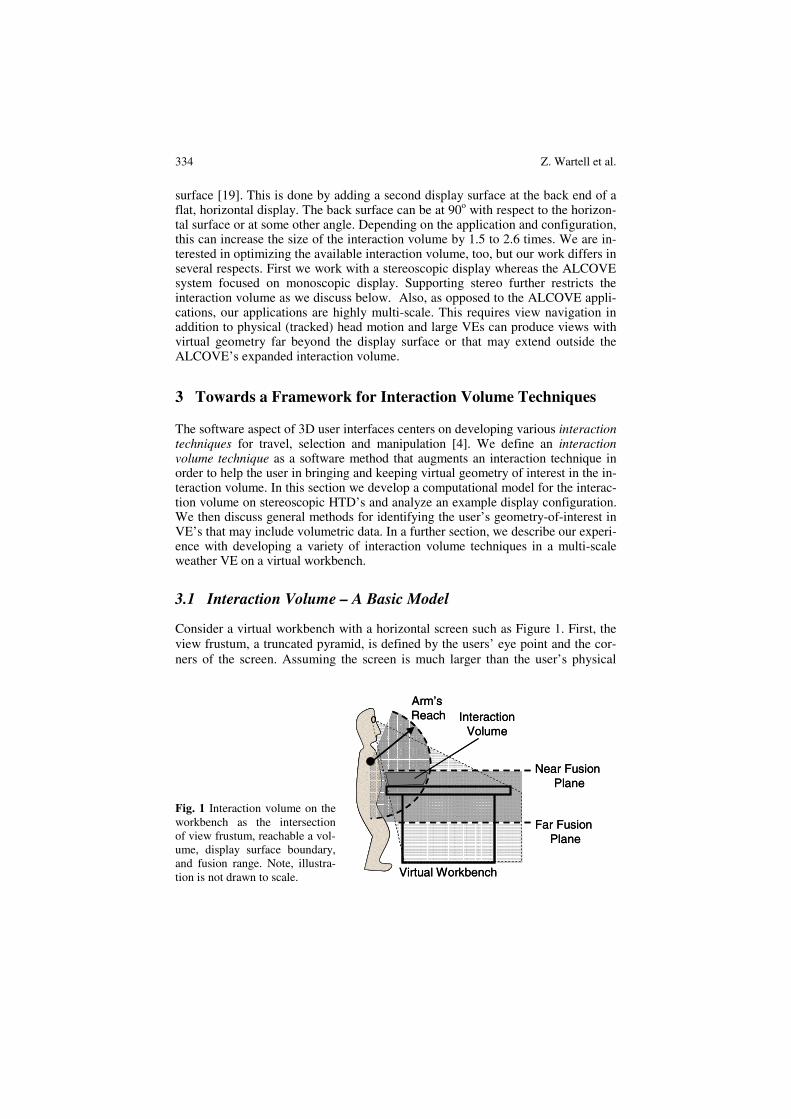
Consider a virtual workbench with a horizontal screen such as Figure 1. First, the view frustum, a truncated pyramid, is defined by the users’ eye point and the cor-ners of the screen. Assuming the screen is much larger than the user’s physical
Fig. 1 Interaction volume on the workbench as the intersection of view frustum, reachable a vol-ume, display surface boundary, and fusion range. Note, illustra-tion is not drawn to scale.
Arm’s Reach
Near Fusion Plane
Far Fusion Plane
Virtual Workbench
InteractionVolume
Arm’s Reach
Near Fusion Plane
Far Fusion Plane
Virtual Workbench
InteractionVolume
Interaction Volume Management in a Multi-scale Virtual Environment 335
eye separation, the left and right frustum will substantially overlap so we consider just a single frustum. Next, stereoscopic displays have a limited volume in which the virtual scene can reside without creating visual discomfort. Literature provides many suggestions on what part of the volume to use in terms of distances in front of and behind the screen. A review of the subject can be found in [48]. In the workbench configuration in Figure 1, two planes are defined, the Nearest Fusion plane, and the Farthest Fusion Plane. Virtual objects in front of the nearest plane or beyond the farthest plane yield negative and positive screen parallaxes that can cause eye strain, visual fatigue and eventually diplopia. Note the figure is not drawn to scale in order to illustrate all volume boundaries.
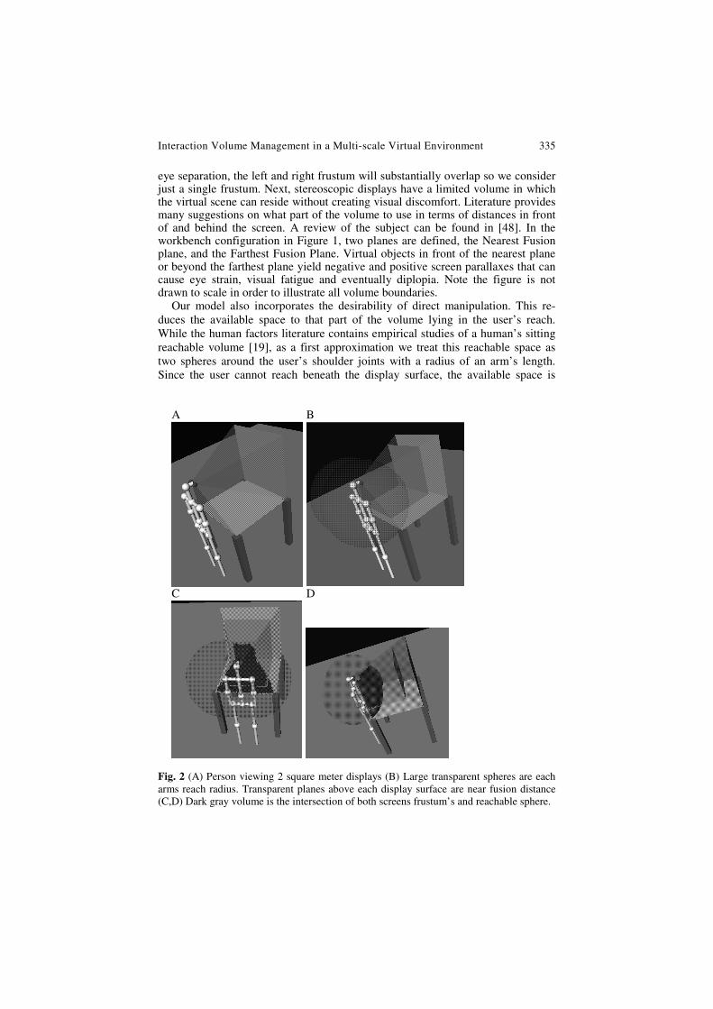
Our model also incorporates the desirability of direct manipulation. This re-duces the available space to that part of the volume lying in the user’s reach. While the human factors literature contains empirical studies of a human’s sitting reachable volume [19], as a first approximation we treat this reachable space as two spheres around the user’s shoulder joints with a radius of an arm’s length. Since the user cannot reach beneath the display surface, the available space is
A B
C D
Fig. 2 (A) Person viewing 2 square meter displays (B) Large transparent spheres are each arms reach radius. Transparent planes above each display surface are near fusion distance (C,D) Dark gray volume is the intersection of both screens frustum’s and reachable sphere.
336 Z. Wartell et al.
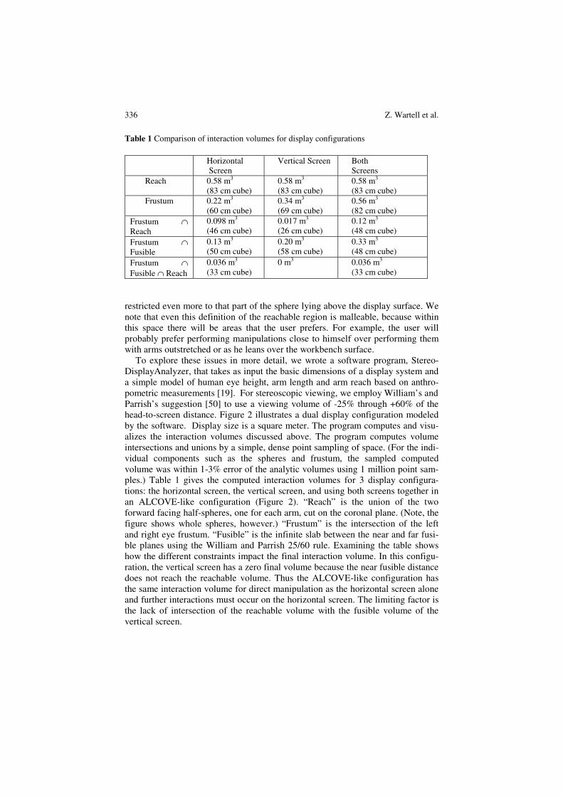
Table 1 Comparison of interaction volumes for display configurations Horizontal
Screen Vertical Screen Both
Screens Reach 0.58 m3
(83 cm cube) 0.58 m3
(83 cm cube) 0.58 m3 (83 cm cube)
Frustum 0.22 m3
(60 cm cube) 0.34 m3 (69 cm cube)
0.56 m3 (82 cm cube)
Frustum ∩ Reach
0.098 m3 (46 cm cube)
0.017 m3
(26 cm cube) 0.12 m3 (48 cm cube)
Frustum ∩ Fusible
0.13 m3 (50 cm cube)
0.20 m3
(58 cm cube) 0.33 m3 (48 cm cube)
Frustum ∩ Fusible ∩ Reach
0.036 m3 (33 cm cube)
0 m3 0.036 m3 (33 cm cube)
restricted even more to that part of the sphere lying above the display surface. We note that even this definition of the reachable region is malleable, because within this space there will be areas that the user prefers. For example, the user will probably prefer performing manipulations close to himself over performing them with arms outstretched or as he leans over the workbench surface.
To explore these issues in more detail, we wrote a software program, Stereo-DisplayAnalyzer, that takes as input the basic dimensions of a display system and a simple model of human eye height, arm length and arm reach based on anthro-pometric measurements [19]. For stereoscopic viewing, we employ William’s and Parrish’s suggestion [50] to use a viewing volume of -25% through +60% of the head-to-screen distance. Figure 2 illustrates a dual display configuration modeled by the software. Display size is a square meter. The program computes and visu-alizes the interaction volumes discussed above. The program computes volume intersections and unions by a simple, dense point sampling of space. (For the indi-vidual components such as the spheres and frustum, the sampled computed volume was within 1-3% error of the analytic volumes using 1 million point sam-ples.) Table 1 gives the computed interaction volumes for 3 display configura-tions: the horizontal screen, the vertical screen, and using both screens together in an ALCOVE-like configuration (Figure 2). “Reach” is the union of the two forward facing half-spheres, one for each arm, cut on the coronal plane. (Note, the figure shows whole spheres, however.) “Frustum” is the intersection of the left and right eye frustum. “Fusible” is the infinite slab between the near and far fusi-ble planes using the William and Parrish 25/60 rule. Examining the table shows how the different constraints impact the final interaction volume. In this configu-ration, the vertical screen has a zero final volume because the near fusible distance does not reach the reachable volume. Thus the ALCOVE-like configuration has the same interaction volume for direct manipulation as the horizontal screen alone and further interactions must occur on the horizontal screen. The limiting factor is the lack of intersection of the reachable volume with the fusible volume of the vertical screen.
Interaction Volume Management in a Multi-scale Virtual Environment 337
These results are specific to a particular display configuration that approximates a variety of available display systems. The StereoDisplayAnalyzer software can be reconfigured to analyze other form factors as well. Our ultimate goal is to have StereoDisplayAnalyzer input a display system’s physical configuration and output a geometric model of the interaction volume. A generic, counter-part software module, which is added to an interactive 3D application, would then use this model to completely automate view parameter adjustment during various interaction methods. The work presented in this chapter is a significant step towards this goal.
Analysis of other physical configurations would be fruitful but is beyond the scope of this chapter; here we simply observe that because the interaction volume is small, it should be treated as a limited commodity. Thus, we should use the in-teraction volume (IV) in the best way possible. When we want to use the volume optimally, the system should determine which part of the VE the user is interested in then adjust the view parameters to bring and keep this geometry-of-interest roughly within the interaction volume. These considerations go beyond Ware et al. [41,42], in that we are proposing to not just pick the nearest visible point in the VE and perform a cyclopean scale to bring that point to the screen, but rather we are proposing to identify the user’s geometry-of-interest, which may be a point, a surface or volume, and bring it into the interaction volume. In our model the inter-action volume is determined based on the specific physical configuration of poten-tially multiple display surfaces and the geometry-of-interest is a point, area or volume determined based on explicit user selection or implicitly during other user interaction. Our goals also differ from scaled-world-grab [22]. Scaled-world-grab temporarily cyclopean scales to bring a selected object within arms reach and after inspection or manipulation the view scale returns to normal. In contrast, our aim is to explore interaction techniques where view scale changes on a continuous, smooth basis and to explore interaction volume management based on a more ex-plicit interaction volume model discussed above.
Certainly there are many techniques available for selection and manipulation at a distance such as extender grab [22], Go-go [33] and HOMER [4]. However, we note that many applications that involve fine manipulations of surface shape [18] or inspection of volumes of data [25] with tools like cutting planes and 6DOF sty-lus’s and probes all tend to use direct manipulation. At present, we limit our inves-tigation to these types of applications where bringing and keeping geometry-of-interest within the interaction volume appears preferable.
3.2 Interaction Volume Techniques
Assuming one has a well-defined interaction volume, next the system must deter-mine the user’s geometry-of-interest (GOI) within the VE. The GOI maybe a point (POI), area (AOI) or volume (VOI). The GOI may be user designated as a natural part of another interaction technique or determined in some automated fashion. The interaction volume technique should bring and keep the geometry-of-interest into the interaction volume. In simple VE’s containing a single object identifying the object-of-interest and bringing it into the interaction volume is trivial. However, in a multi-scale virtual environment both tasks are complicated. First,
338 Z. Wartell et al.
we assume that the geometry-of-interest cannot be determined a-priori. Instead, the user discovers the geometry-of-interest through exploration of the data at vary-ing view scales. The user starts with an overview of the dataset and performs exploratory 7DOF navigation. As he identifies interesting details he zoom’s in. Then as he searches for other details and does comparisons, or as he needs to re-gain spatial context, he zooms out. During this 7DOF navigation, we wish to iden-tify the geometry-of-interest and bring and keep it in the interaction volume by semi-automating various 7DOF view parameters. The semi-automation should not cause abrupt or disorientating view changes and must be balanced against user navigation control.
For example, in cyclopean zooming in each frame the user specifies a view translation and then the POI is determined by sampling the visible VE geometry to find the nearest geometric point. A cyclopean scale brings this near point to the screen. In our scaling-oriented POI navigation the user designates a POI and the system scale zooms about this POI. The system then treats the local surface region as an area-of-interest and performs automatic rotation and translation to keep the AOI in the screen. In scale-world-grab, the user selects an object and the system cyclopean scales the entire world to bring the object temporarily to the user’s hand.
4 Interaction Volume Techniques for a Multi-scale Weather VE
Below we discuss the design of our current interaction volume techniques for a multi-scale weather VE on a virtual workbench. First, we describe the initial sys-tem that supported navigation over multi-scale terrain without volumetric weather data. Then we describe the basic one and two-handed interaction techniques that we added to the system to allow the user to explore volumetric weather data. We will first describe these techniques as we implemented them prior to considering interaction volume management. Then we will discuss the evolution of our inter-action volume techniques.
4.1 The Initial System
Above we reviewed our original scaling-oriented POI navigation technique for a multi-scale, global terrain system [44]. We also added a Bat fly mode with cyclo-pean zooming [43] with a minor change in that we continue to use strict cyclopean scaling but the cyclopean scaling is only engaged during active navigation. A 6DOF gesture switches between the cyclopean zooming and scaling POI modes. Jang et al. added a global volumetric rendering subsystem for displaying Doppler weather radar data on top of the terrain system [13]. Rendering is splat based. It is multi-resolution and dynamically paged. The system is theoretically capable of displaying every Doppler radar sample point of all 150 U.S. continental Doppler radars. This multi-resolution, volumetric visualization is multi-scale and meteor-ologists are interested in features that occur over the multiple scales. The volumet-ric data is also temporally varying.
Interaction Volume Management in a Multi-scale Virtual Environment 339
We implemented a variety of two-handed user interface tools based on Shaw and Green’s compact, 3 button 6DOF devices [34]. Each device, or “bat”, has a corresponding 3D cursor in the virtual environment. A key tool is a user created “conditional box” that defines the volumetric region of interest (VOI). We devel-oped a two-handed interface for positioning and manipulating conditional boxes. The conditional box is so named because selected conditions can be placed on its contents [14]. They are used to select and demark subsets of volumetric data and are analogous in concept to a volumetric 3D magic lens [39]. In addition to acting as a user controlled data filter, the conditional box defines the volume where high-er detailed rendering occurs. With complex and dynamically paged data, the system often cannot render the entire dataset at highest-detail while maintaining interactive frame rates. Further in dense volumetric datasets, selectively rendering only within the conditional box helps keep central details from being obscured or occluded by surrounding volumetric data.
The user can create up to two condition boxes that can be resized and moved independently with each hand. Since Doppler weather radar contains multiple vo-lumetric fields, it is useful to use one box as a lens into one field and the second box as a lens into a second field and use each hand to grab-n-drag a separate box to explore correlations among these volumetric fields. Box grab-n-drag moves the boxes through volumetric field selecting different regions. Once a satisfactory volume is selected, we need to navigate around the box. The scaling POI and cy-clopean zooming techniques are not well suited to inspecting the contained data; hence we added a grab-n-drag navigation mode (also called scene-in-hand [40]). Here the user grabs the world from within the boxed data volume and can directly translate and reorient the data volume for closer inspection. We developed a num-ber of additional one and two-handed tools such as a cutting plane to slice through the volume data, a 3D measuring tool to measure distances between points in 3D space and several probe tools to inspect the actual data values associated with individual splats and volumes.
4.2 Adding Interaction Volume Management
All these tools are easiest to manipulate within the interaction volume using direct manipulation. While using these tools we found that the IV aware cyclopean zoom and scaling POI travel techniques were suboptimal when using these tools for in-specting the volume data. Our POI technique keeps the terrain surface flush with the display screen which conflicts with the view grab-n-drag travel’s ability to view the boxed volume data from the side. Also, it is much harder to circle around a boxed volume using cyclopean zooming technique than using the view grab-n-drag. However, standard view grab-n-drag is has no IV management.
Scaling Grab-n-drag
Initially we added an independent two-handed, scaled zooming gesture [5]. How-ever, we found we often had to switch between the view grab-n-drag and scaled zooming gestures when navigating and inspecting the volume data. Hence, we re-placed the view grab-n-drag with a scaling grab-n-drag. This scaling grab-n-drag
340 Z. Wartell et al.
used cyclopean scale for IV management. Initially, the POI for the cyclopean scale was the closest terrain point. This reduced the frequency of use of the manually scaled zoom, but did not eliminate its use.
Still we found that when trying to manipulate the condition boxes, such as grabbing a corner to resize them, or grabbing their interior to move them, we con-tinued to have difficulty quickly positioning the 3D cursors to directly grab these targets. Part of the problem was that the scaling grab-n-drag’s cyclopean scale brought the nearest terrain point directly onto the screen. While the volume data generally lies far above the terrain surface, during side views this often does not place the volume data, and hence the condition boxes, above the display surface in the interaction volume. Our solution was to switch the IV management’s target POI from the nearest terrain point to the VOI defined by the condition box itself. (If the condition box is out of view, then the cyclopean scale POI reverts to the nearest terrain point).
We started with a single condition box solution and with the assumption that the IV technique should bring entire condition box into the interaction volume. However, initial development and testing proved this is often hard to do without creating abrupt and unpredictable view changes. First, cyclopean scale alone has only one degree of freedom. This is enough to bring either the farthest corner of the box to the bottom of the interaction volume, or the nearest corner to the top of the interaction volume. To completely place the condition box in the interaction volume would require combining cyclopean scale with view translation or possi-bly using a view scale about another fixed point. Additionally, we found that if we disabled interaction volume management, we typically positioned the box in such a way that the part of most interest is slightly above the workbench surface with-out being too concerned that the entire box is at or above the surface. Therefore, we choose for scaled grab-n-drag’s cyclopean scale to bring the nearest corner of the box to the upper surface of the interaction volume.
Since the positions and even shapes of the fusion planes are fuzzy, we decided to test further by varying the position of the top surface of the interaction volume. We varied this height while using the scaled grab-n-drag and judged the affect of different heights on two criteria, the ease of direct manipulation of the condition box and how good the stereoscopic effect was. With respect to direct manipula-tion, we found that it is best to raise the conditional box above the display surface. Not only is the box more convenient to reach, but the user is less likely to bump the display surface when making large downward motions. With respect to stere-oscopy, we found, that the stereoscopic effect is more pronounced the nearer the box is to the user. However, if the box is placed too high, the user is strained fus-ing the images together. We found that, given an average distance between the eyes and the display surface of 75 cm, raising the interaction volume’s top plane 30 cm above the display surface is a good compromise allowing easy manipula-tion whilst not causing stereoscopic problems. This is somewhat higher than Wil-liams and Parrish suggestion with 30 cm being 40% of the head-to-screen distance as opposed to their suggestion of 25% [50]. Not surprisingly, when considering both direct manipulation and stereo, the boundaries of the interaction volume
Interaction Volume Management in a Multi-scale Virtual Environment 341
should be thought of not as sharp surfaces but as volumetric regions of varying trade-offs between encompassing more of the reachable space and using a more conservative stereo depth range.
In addition to scaling grab-n-drag, which is view a manipulation, we also have to contend with the box grab-n-drag and box manipulation. Recall, these two interactions move and resize the condition box within VE in order to select other regions of volume data. During these interactions, the IV management also per-forms a cyclopean scale to bring the nearest box corner to the top IV surface. As a concrete example, if the user grabs one box corner and raises it upward to expand the box perpendicular to the screen surface, the box corner will appear to stick to the top IV surface while a cyclopean scale causes the rest of the world to expand and thus the box extends in the pulled direction. The alternative, to disable IV management during box manipulation, would instead allow the user to draw that box corner high above the top IV surface, and then if and when the user engaged the (view) scaling grab-n-drag, the IV management adjust the view to bring that corner onto the top IV surface.
Finally, we note that we have not explicitly addressed the Far Fusible Depth plane and we allow objects to lie beyond this distance. We decided to not enforce a Farthest Fusible limit for several reasons. First, anecdotally it has not been too much of a problem. Our interaction tools are set up so that the object of interest to the user will be lying close to the user, hence objects beyond the Farthest Fusi-ble plane will a priori be of less interest. We surmise that the user therefore tends not to fixate on the distant objects. While this can leave distant objects diploptic, if the user does not fixate frequently on the distant objects the accommoda-tion/vergence conflict for these distant objects comes into play less frequently. Second, we do not want to compress the display space to control far fusion prob-lems (by using false eye separation, etc. [47]) because using a distorting fusion control method will also distort the near virtual objects to which the user is attend-ing. One option is to use a non-distorting fusion control method. For example, setting the far clipping plane to the far fusible depth. However, this may cause the user to lose visual spatial context since the background geometry would be elided. Alternatively, one can implement depth-of-field blurring which may reduce diplo-pia. A second option is to apply a different distortion to distant geometry than to near geometry. This is mathematically challenging, however [48]. While this dif-ferential compression has been recently demonstrated in non-tracked displays [24], our experience with mathematically similar compression transformations, applied to head-tracked displays, has yielded very disappointing results due to the effects on perceived motion parallax [48].
Multiple Boxes
There is also the challenge of divided attention. If needing to understand the rela-tions between two or more variables, the user may want more than one condition box. We support the particular case of two boxes, which can be different sizes and freely positioned with respect to one another using two hands. In a typical
342 Z. Wartell et al.
situation, the user would freely move the two boxes about each other, one in each hand, to study the spatial correlation between 3D fields. Where should the vol-ume-of-interest be for driving interaction volume management?
We first tried employing a bounding box around both boxes (oriented so that the bounding box would have the smallest footprint) and then positioning the bounding box in the interaction volume. This could, of course, extend to any num-ber of conditional boxes. However, we found several situations where this proce-dure produced less optimal interaction and stereo display results. These include when the boxes are not close to one another or when one box is much larger than the other. These problems might be avoided by defining a set of rules on when to actually use a bounding box instead of a single condition box. We tried using a bounding box only when the sizes of both boxes did not differ too much and their distance apart was less than a certain threshold. Unfortunately, manipulation with these rules sometimes resulted in continuous switching between the bounding box and a single conditional box. Depending on the sizes and positions of the boxes, this would modify the stereo view, making fusing the image rather unpleasant.
This switching of bounding boxes amounts to an implicit change of focus, which probably makes occasional viewing problems unavoidable for the user. We concluded that the change of focus (in the display) to a certain box should be lim-ited to when the user is actually focused on that specific box (i.e., when she is manipulating it). The transition becomes more acceptable this way, because it only takes place when the user starts or stops manipulating the conditional box. At that moment, the eyes are mainly focused on the box itself, causing everything around it, including the transition, to become almost unnoticeable.
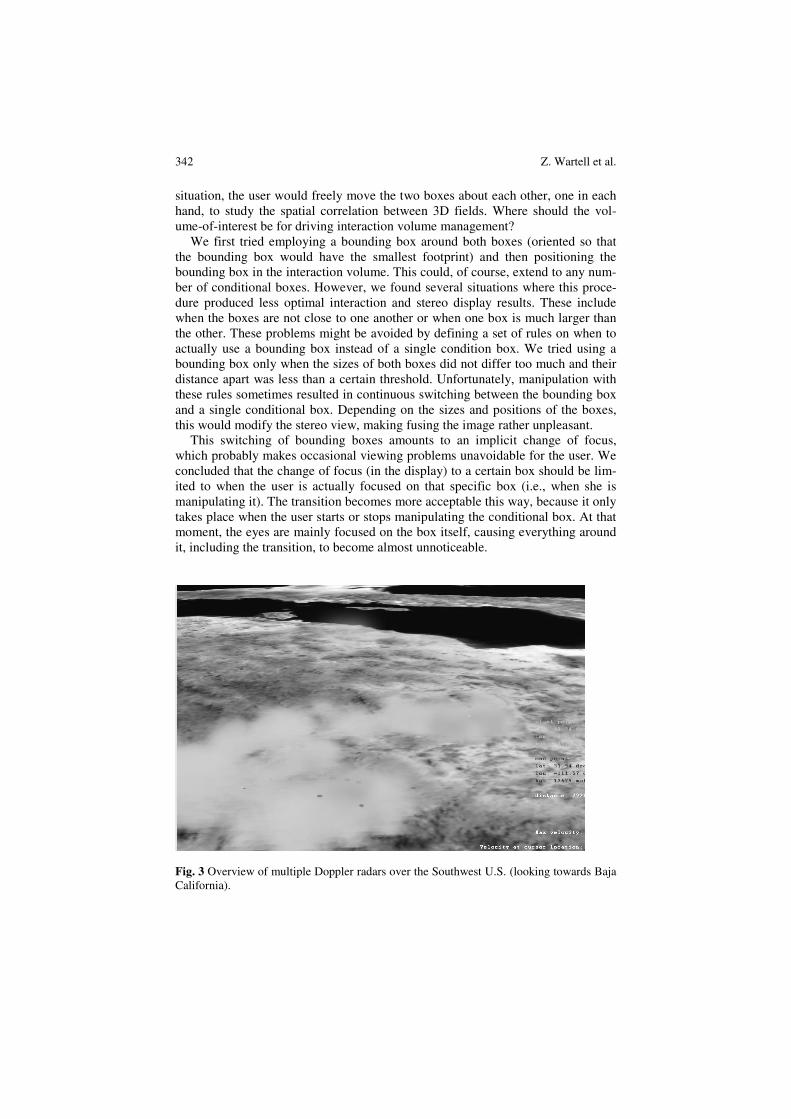
Fig. 3 Overview of multiple Doppler radars over the Southwest U.S. (looking towards Baja California).
Interaction Volume Management in a Multi-scale Virtual Environment 343
When the user is manipulating both boxes, the one closest to the user is chosen as the point of focus. This gives the best result and allows for the best placement within the interaction volume. If the distance between the box and the user is almost the same for both boxes, either the user has not decided on what to focus or the boxes are usually close enough to each other that they are both in the interac-tion volume.
4.3 Results
To evaluate and validate our approach, we used multiple time steps from a large severe storm, which included tornados, centered around Phoenix, AZ and spread over several thousand square miles. Six overlapping 3D Doppler weather radars captured the storm. In overview the user sees the whole storm pattern within the context of the southwestern U.S (Figure 3). The Doppler radars collect multiple 3D fields including reflectivity and velocity. These fields are rendered as multi-resolution volumetric structures [12], and the user can fly in to see phenomena at a resolution of under 1 Km. The reflectivity provides 3D precipitation intensity; combined with other data, it can even tell the type of precipitation. The velocity tells the severity of winds and shows localized wind shear effects that may indicate tornados.
To give an impression of how this environment is explored, we describe a typi-cal user scenario. At first, the user is presented with a view of the entire earth, and the overview mode is active. The user now uses the zooming and panning tools to go to an area of weather in which he is interested, for example the West Coast of the U.S. Typically the reflectivity data are shown in overview, since these show the rainfall pattern and the positions of storm fronts. Using his right hand the user now creates an initial conditional box around the rough area of interest and zooms towards it. When the box is within a certain range, the system automatically switches to close-range interaction. At the same time, the box is elevated so that the nearest part lies in the interaction volume. The box is now in reach of the user. The user now creates either a new box more precisely around his volume of inter-est, or he simply resizes the current box by dragging the corners to the desired positions. Using scaling grab-n-drag, to zoom and orbit the box, he positions him-self to have a good viewpoint of the region. The user now creates another condi-tional box for the velocity data to perform a correlative analysis (Figure 4). After creating the second box, he moves both of them around using box grab-n-drag with each hand and investigates the interplay amongst the data. Finally, after he is done, he zooms out again. The overview interaction mode becomes available and the user is ready to navigate to another part of the globe to start the process all over again.
In this scenario when we compare our new approach to the earlier situation where the IV management geometry-of-interest was the terrain instead of the con-ditional box, a couple of things are immediately noticeable. In the old situation, the box was often hard to get a hold of, because it would often lie out of reach. This is because if the user navigates to a point outside the box, the box will often be below the display surface (due to the fact that the point of navigation is pushed

344 Z. Wartell et al.
Fig. 4 Positioning two conditional boxes for correlative analysis of detailed weather (shown with both stereo images).
above display for good stereo effect, but the rest of the earth curves downward be-low the display [44]. Much navigation was required to be able to directly grasp a corner. This is not necessary with the new approach and, because of positioning of the box in the interaction volume and good stereoscopic viewing, selecting and probing the data is also much easier.
The mapping of hand movements to pitch, yaw, and roll is intuitive in scaling grab-n-drag. The user can, for example, move the box and its contents from top view to side view in one movement. (This is important for this application in that forecasters want to see the detailed relation of weather patterns to the ground.) In addition, the user can make precise changes of orientation and then return to the original view.
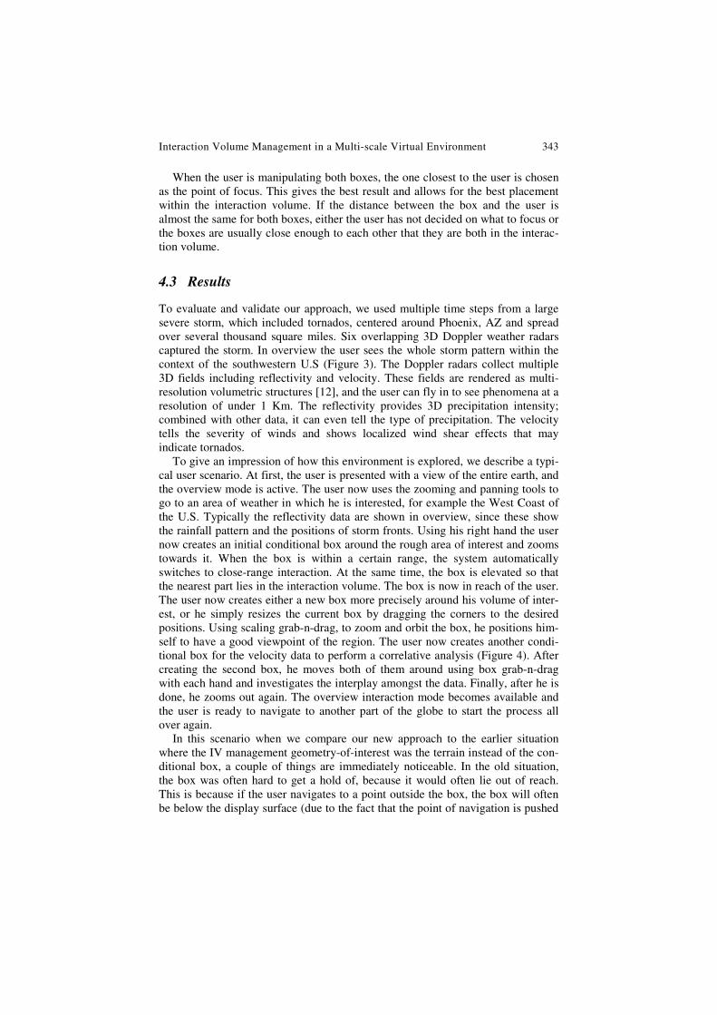
As stated above, one can increase the interaction volume by having non-direct manipulation methods and these are sometimes a better choice than direct methods. For example in the scenario above, the user created the conditional box by an indi-rect method, casting rays on the earth’s surface. We also use a cutting plane to let the user investigate an area that might otherwise be beyond his reach (Figure 5). The cutting plane sweeps out an adjacent slice of the volume. As shown in Figure 5, the user grabs one corner and then can position or orient the cutting plane at will. It is thus an extended reach probe that quickly investigates the detailed internal structure of a volume.
The balancing of interaction and stereoscopic viewing needs has a significant impact. The user can interact with the region of focus quickly and comfortably. Direct manipulations involving 3D selection that were more difficult to make in
Interaction Volume Management in a Multi-scale Virtual Environment 345
Fig. 5 Extended reach interaction using the cutting plane.
the monoscopic state, such as grabbing the edge or corner of the box, placing a cutting plane precisely in the 3D volume, or positioning 3D probes for measuring, are significantly easier to accomplish. Our procedure for handling two boxes works reasonably well for stereoscopic viewing, especially when the boxes are close to one another (or one is inside the other). This is usually the case since the user will typically want the boxes close to better study correlations. As with other interactions, the positioning for good stereo viewing increases the understanding of depth and shape, which in this case aids in the correlative analysis.
One thing that has become apparent in this detailed investigation is that care must be taken in the volume rendering to preserve the stereoscopic effect. In our rendering scheme, splat size and transparency affected stereo rendering. A splat overlap appropriate for the weather volume sampling density [49], although it gave reasonable visual quality in the monoscopic case, greatly reduced the stereo depth effect in close-up views. Smaller splats were necessary to retain the stereo effect. Transparency also reduces the stereo effect. These problems can probably be reduced by applying a better volume shading model that uses density gradients as normals. The optimization of stereo volume rendering has not been studied much and more investigation is needed.
Our results have given an unexpected new insight. Having good stereo at all stages of an investigation give a significantly different impression of the 3D space. The user starts relying on stereo as a constant and reliable cue. More depth and relational information is always displayed, with or without rotation and motion parallax or other interactions. For example, if a reflectivity volume is sliced or has
346 Z. Wartell et al.
a hole, the user can distinguish the interior field much more easily than in a mono-scopic interactive view. This suggest new tools that would be especially useful with reliable stereoscopic viewing. For example, a probe could remove a “core sample” of a volume, revealing the depth and relative positioning of its inner structure. There can be disadvantages as well. Artifacts, such as those due to uni-formly sampled splats at lower resolution (a uniform volume tree is used in this case [12]) will pop out more than in a monosocopic view. This can be distracting, but it is balanced to an extent by the fact that the depth relation between inner and outer structure is always more apparent in stereo.
5 Conclusion and Future Work
In this chapter we described the interaction volume for different large display con-figurations under the need for both direct manipulation and stereoscopic display. We found that there was a trade-off between these two aspects but that negative effects could be minimized by the use of appropriate interaction tools and identi-fied geometries-of-interest. We implemented these ideas for a virtual workbench environment and applied them to a multi-scale weather application.
The choices made for the interaction volume and the trade-offs between inter-action and stereoscopy were successful. Interaction with objects in the multi-scale space was comfortable and effective. Stereoscopic viewing produced good depth and shape effects. Of course, the evaluations carried out here are only qualitative descriptors. It would be useful to get a quantitative measure of the improvement in interaction and stereoscopy by performing thorough user studies. In particular these studies could more clearly bring out the role of the fusion limits in an inter-active environment where the user attention is focused on a particular part of the display.
We also found that given the limited size of the interaction volume, there is a trade-off to be made when choosing between interaction paradigms. Direct manipulation is intuitive to use, but severely restricts the usable volume, whereas ray-based tools allow the largest usable volume, but are harder to use. Extended reach based tools represent a compromise between both criteria.
References
1. Lyn, B., Ho, A., Dill, J., Henigman, F.: The Continuous Zoom: A Constrained Fisheye Technique for Viewing and Navigating Large Information Spaces. In: Proceedings of ACM UIST 1995, pp. 207–215 (1995)
2. Bederson, B.B., Holland, J.D.: Pad++: A Zooming Graphical Interface for Exploring Alternate Interface Physics. In: Proceedings of ACM UIST 1994, pp. 17–26 (1994)
3. Bowman, D.A., Koller, D., Hodges, L.F.: Travel in Immersive Virtual Environments: An Evaluation of Viewpoint Motion Control Techniques. In: Proceedings of IEEE VRAIS 1997, pp. 45–52 (1997)
4. Bowman, D.A., Kruijff, E., LaViola, J.J., Poupyrev, I.: 3D User Interfaces: Theory and Practice. Addison-Wesley Professional, Reading (2004)
Interaction Volume Management in a Multi-scale Virtual Environment 347
5. Cutler, L.D., Fröhlich, B., Hanrahan, P.: Two-handed direct manipulation on the re-sponsive workbench. In: Proceedings of the 1997 Symposium on interactive 3D Graphics, SI3D 1997, Providence, Rhode Island, United States, April 27 - 30, 1997, pp. 107–114. ACM, New York (1997)
6. Cruz-Neira, C., Sandin, D.J., DeFanti, T.A.: Surround-screen projection-based virtual reality: the design and implementation of the CAVE. In: SIGGRAPH 1993 Conference Proceedings, Annual Conference Series, ACM SIGGRAPH, pp. 135–142. Addison Wesley, Reading (1993)
7. Deering, M.: High Resolution Virtual Reality. Computer Graphics 26(2), 195–202 (1992)
8. Donelson, W.C.: Spatial management of information. In: SIGGRAPH 1978: Proceed-ings of the 5th annual conference on Computer graphics and interactive techniques, pp. 203–209. ACM Press, New York (1978)
9. Fröhlich, B., Krish, B., Krüger, W., Wesche, G.: Further Development of the Respon-sive Workbench. In: Virtual Environments 1995, Selected Papers of the Eurographics Workshops, pp. 237–246 (1995)
10. Furnas, G.W.: Generalized fisheye views. In: Proceedings of CHI 1986, pp. 16–23 (1986)
11. Hong, l., Muraki, S., Kaufman, A., Bartz, D., He, T.: Virtual voyage: interactive navi-gation in the human colon. In: Proc. SIGGRAPH 1997, pp. 27–34 (1997)
12. Houtgast, E., Pfeiffer, O., Wartell, Z., Ribarsky, W., Post, F.: Navigation and interac-tion in a multi-scale stereoscopic environment. In: Fröhlich, B., Julier, S., Takemura, H. (eds.) Proc. IEEE Virtual Reality 2005, pp. 275–276. IEEE Computer Society Press, Los Alamitos (2005)
13. Jang, J., Ribarsky, W., Shaw, C., Faust, N.: View-Dependent Multiresolution Splatting of Non-Uniform Data. In: Eurographics-IEEE Visualization Symposium 2002, pp. 125–132 (2002)
14. Jean, Y., Ribarsky, M., Kindler, T., Gu, W., Eisenhauer, G., Schwan, K., Alyea, F.: An Integrated Approach for Steering, Visualization, and Analysis of Atmospheric Simula-tions. In: Proc. Visualization 1995, pp. 383–387 (1995)
15. Kopper, R., Ni, T., Bowman, D., Pinho, M.: Design and Evaluation of Navigation Techniques for Multiscale Virtual Environments. In: IEEE Virtual Reality 2006, Alex-andria, Virginia, USA, March 25-29, 2006, pp. 181–188 (2006)
16. LaViola Jr., J.J., Feliz, D., Keefe, D., Zeleznik, R.: Hands-free multi-scale navigation in virtual environments. In: Proceedings of the 2001 symposium on Interactive 3D graphics, pp. 9–15. ACM Press, New York (2001)
17. Leigh, J., Johnson, A., Vasilakis, C., DeFanti, T.: Multi-perspective Collaborative De-sign in Persistent Networked Virtual Environments. In: Proceedings of the IEEE Vir-tual Reality Annual International Symposium, pp. 253–260, 271–272 (1996)
18. Llamas, I., Kim, B., Gargus, J., Rossignac, J., Shaw, C.: Twister: A Space-Warp Op-erator for the Two-Handed Editing of 3D Shapes. In: Proc. SIGGRAPH 2003, pp. 663–668 (2003)
19. McCormick, J.: Work Space and Personal Equipment. In: Human Factors Engineering, ch. 11, 2nd edn., McGraw-Hill book Company, New York (1964)
20. Mackinlay, J., Card, S., Robertson, G.: Rapid controlled movement through a virtual 3D workspace. In: Proceedings of the 17th annual conference on Computer graphics and interactive techniques, pp. 171–176. ACM Press, New York (1990)
21. Meyer, M., Barr, A.: ALCOVE: design and implementation of an object-centric virtual environment. In: IEEE Virtual Reality 1999, pp. 46–52 (1999)
348 Z. Wartell et al.
22. Mine, M.R., Brooks Jr., F.P., Sequin, C.H.: Moving Objects In Space: Exploiting Pro-prioception In Virtual-Environment Interaction. In: Computer Graphics Proceedings, ACM SIGGRAPH 1997, pp. 19–26 (1997)
23. Munzner, T., Guimbretiere, F., Tasiran, S., Zhang, L., Zhou, Y.: TreeJuxtaposer: Scal-able Tree Comparison using Focus+Context with Guaranteed Visibility. In: Proc. SIGGRAPH 2003, pp. 453–462 (2003)
24. Holliman, N.S.: Mapping perceived depth to regions of interest in stereoscopic images. In: Proceedings of SPIE-IS&T Electronic Imaging, SPIE, vol. 5194 (2004) ISBN 0-8194-5194
25. Hinckley, K., Pausch, R., Proffitt, D., Kassell, N.F.: Two-handed virtual manipulation. ACM Trans. Comput.-Hum. Interact. 5(3), 260–302 (1998)
26. Obeysekare, U., Williams, C., Durbin, J., Rosenblum, L., Rosenberg, R., Grinstein, F., Ramamurti, R., Landsberg, A., Sandberg, W.: Virtual workbench - a non-immersive virtual environment for visualizing and interacting with 3D objects for scientific visu-alization. In: Proc. IEEE Visualization 1996, pp. 345–349 (1996)
27. Pausch, R., Burnette, T., Brockway, D., Weiblen, M.E.: Navigation and locomotion in virtual worlds via flight into hand-held miniatures. In: Proceedings of the 22nd annual conference on Computer graphics and interactive techniques, pp. 399–400. ACM Press, New York (1995)
28. Pierce, J.S., Forsberg, A.S., Conway, M.J., Hong, S., Zeleznik, R.C., Mine, M.R.: Im-age plane interaction techniques in 3D immersive environments. In: Proceedings of the 1997 symposium on Interactive 3D graphics, p. 39. ACM Press, New York (1997)
29. Pierce, J.S., Pausch, R.: Navigation with Place Representations and Visible Land-marks. In: VR 2004: Proceedings of the IEEE Virtual Reality 2004, p. 173. IEEE Computer Society, Los Alamitos (2004)
30. Pierce, J., Pausch, R.: Comparing Voodoo Dolls and HOMER: Exploring the Impor-tance of Feedback in Virtual Environments. In: Proc. ACM CHI 2002, pp. 105–112 (2002)
31. Robinett, W., Holloway, R.: Implementation of flying, scaling and grabbing in virtual worlds. In: Proceedings of the 1992 symposium on Interactive 3D graphics, pp. 189–192. ACM Press, New York (1992)
32. van de Pol, R., Ribarsky, W., Hodges, L., Post, F.: Interaction in Semi-Immersive Large Display Environments. In: Report GIT-GVU-98-30, Eurographics Virtual Envi-ronments 1999, pp. 157–168. Springer, Heidelberg (1999)
33. Poupyrev, I., Billinghurst, M., Weghorst, S., Ichikawa, T.: The Go-Go Interaction Technique: Non-Linear Mapping for Direct Manipulation in VR. In: Proc. ACM UIST 1996, pp. 79–80 (1996)
34. Shaw, C., Green, M.: Two-handed polygonal surface design. In: Proceedings of the 7th Annual ACM Symposium on User interface Software and Technology, UIST 1994, Marina del Rey, California, United States, November 02-04, 1994. ACM, New York (1994)
35. Southard, D.A.: Transformations for Stereoscopic Visual Simulation. Computer & Graphics 16(4), 401–410 (1992)
36. Southard, D.A.: Viewing Model for Virtual Environment Displays. Journal of Elec-tronic Imaging 4(4), 413–420 (1995)
37. Stoakley, R., Conway, M., Pausch, R.: Virtual Reality on a WIM: Interactive Worlds in Miniature. In: Proceedings of CHI 1995 Mosaic of Creativity, pp. 266–272 (1995)
Interaction Volume Management in a Multi-scale Virtual Environment 349
38. Stanislav, L., Stoev, D.S., Straßer, W.: Two-Handed Through-The-Lens-Techniques for Navigation in Virtual Environments. In: Eurographics Workshop on Virtual Envi-ronments, pp. 16–18 (2001)
39. Viega, J., Conway, M.J., Williams, G., Pausch, R.: 3D magic lenses. In: UIST 1996: Proceedings of the 9th annual ACM symposium on User interface software and tech-nology, pp. 51–58. ACM, New York (1996)
40. Ware, C., Osborne, S.: Exploration and virtual camera control in virtual three dimen-sional environments. In: Proceedings of the 1990 symposium on Interactive 3D graph-ics, pp. 175–183. ACM Press, New York (1990)
41. Ware, C.: Dynamic Stereo Displays. In: Proceedings of CHI 1995 Mosaic of Creativ-ity, pp. 310–316 (1995)
42. Ware, C., Gobrecht, C., Paton, M.: Algorithm for Dynamic Disparity Adjustment. In: Proc. of the SPIE: Stereoscopic Displays and Virtual Reality Systems II, vol. 2409, pp. 150–156 (1995)
43. Ware, C., Fleet, D.: Integrating flying and fish tank metaphors with cyclopean scale. In: Proceedings of Computer Graphics International 1997, pp. 39–46 (1997)
44. Wartell, Z., Ribarsky, W., Hodges, L.: Third Person Navigation of Whole-Planet Ter-rain in a Head-tracked Stereoscopic Environment. Report GIT-GVU-98-31. In: IEEE Virtual Reality 1999 pp. 141–149 (1999)
45. Wartell, Z., Hodges, L., Ribarsky, W.: Distortion in Head-Tracked Stereoscopic Dis-plays Due to False Eye Separation. In: ACM SIGGRAPH 199, pp. 351–358 (1999)
46. Wartell, Z., Hodges, L., Ribarsky, W.: Characterizing Image Fusion Techniques in Stereoscopic HTDs. In: Proceedings of Graphics Interface 2001, Ottawa, Canada, June 2001, pp. 223–232 (2001)
47. Wartell, Z.: Stereoscopic Head-Tracked Displays: Analysis and Development of Dis-play Algorithms. Ph.D. dissertation (August 2001)
48. Westover, L.: Footprint evaluation for volume rendering. In: Proc. SIGGRAPH 1990, pp. 367–376 (1990)
49. Williams, S., Parrish, R.: New Computational Control Techniques and Increased Un-derstanding for Stereo 3-D Displays. In: Stereoscopic Displays and Applications, SPIE, vol. 1256, pp. 73–82 (1990)
50. Woodson, W.E.: Human Factors Design Handbook: Information and Guidelines for the Design of Systems. In: Facilities, Equipment and Products for Human Use. McGraw-Hill Book Company, New York (1981)
51. Zhang, X., Furnas, G.W.: mCVEs: Using Cross-Scale Collaboration to Support. User Interaction with Multiscale Structures. Presence: Teleoperator and Virtual Environ-ments 14(1), 31–46 (2005)
