interface management - omgwiki.orgsysml-roadmap:ecss-e-st-10... · space engineering . interface...
TRANSCRIPT

ECSS-E-ST-10-24C 1 June 2015
Space engineering Interface management
ECSS Secretariat ESA-ESTEC
Requirements & Standards Division Noordwijk, The Netherlands

ECSS-E-ST-10-24C 1 June 2015
Foreword
This Standard is one of the series of ECSS Standards intended to be applied together for the management, engineering and product assurance in space projects and applications. ECSS is a cooperative effort of the European Space Agency, national space agencies and European industry associations for the purpose of developing and maintaining common standards. Requirements in this Standard are defined in terms of what shall be accomplished, rather than in terms of how to organize and perform the necessary work. This allows existing organizational structures and methods to be applied where they are effective, and for the structures and methods to evolve as necessary without rewriting the standards.
This Standard has been prepared by the ECSS E-ST-10-24C Working Group, reviewed by the ECSS Executive Secretariat and approved by the ECSS Technical Authority.
Disclaimer
ECSS does not provide any warranty whatsoever, whether expressed, implied, or statutory, including, but not limited to, any warranty of merchantability or fitness for a particular purpose or any warranty that the contents of the item are error-free. In no respect shall ECSS incur any liability for any damages, including, but not limited to, direct, indirect, special, or consequential damages arising out of, resulting from, or in any way connected to the use of this Standard, whether or not based upon warranty, business agreement, tort, or otherwise; whether or not injury was sustained by persons or property or otherwise; and whether or not loss was sustained from, or arose out of, the results of, the item, or any services that may be provided by ECSS.
Published by: ESA Requirements and Standards Division ESTEC, P.O. Box 299, 2200 AG Noordwijk The Netherlands Copyright: 2015© by the European Space Agency for the members of ECSS
2

ECSS-E-ST-10-24C 1 June 2015
Change log
ECSS-E-ST-10-24C
1 June 2015
First issue
3
ECSS-E-ST-10-24C 1 June 2015
Table of contents
Change log ................................................................................................................. 3
Introduction ................................................................................................................ 6
1 Scope ....................................................................................................................... 7
2 Normative references ............................................................................................. 8
3 Terms, definitions and abbreviated terms ............................................................ 9
3.1 Terms from other standards ...................................................................................... 9
3.2 Terms specific to the present standard ..................................................................... 9
3.3 Abbreviated terms................................................................................................... 11
3.4 Nomenclature ......................................................................................................... 11
4 Principles .............................................................................................................. 12
4.1 Type of interfaces ................................................................................................... 12
4.2 Interface management process............................................................................... 12
4.2.1 General description ................................................................................... 12
4.2.2 Interface management planning ................................................................ 13
4.2.3 Interface identification ............................................................................... 14
4.2.4 Interface requirements specification .......................................................... 14
4.2.5 Interface definition ..................................................................................... 15
4.2.6 Interface approval and control ................................................................... 15
4.2.7 Interface verification and validation ........................................................... 18
4.3 Interface management life cycle ............................................................................. 18
4.3.1 Generic interface management life cycle ................................................... 18
4.3.2 Space element – Launch segment interface management life cycle ......... 20
4.3.3 Space segment - Ground segment interface management life cycle ......... 21
4.3.4 Interface management life cycle involving OTS products .......................... 22
5 Requirements ........................................................................................................ 23
5.1 Interface management planning .............................................................................. 23
5.2 Interface identification ............................................................................................. 23
5.3 Interface requirements specification ....................................................................... 24
4
ECSS-E-ST-10-24C 1 June 2015
5.4 Interface definition .................................................................................................. 24
5.5 Interface control and approval ................................................................................ 26
5.6 Interface verification and validation ......................................................................... 26
Annex A (normative) Interface Requirements Document (IRD) - DRD ................ 27
Annex B (normative) Interface Control Document (ICD) – DRD .......................... 30
Annex C (normative) Interface Definition Document (IDD) or Single-end Interface Control Document – DRD ................................................................... 34
Annex D (informative) Proposed content of an "Interface Identification Document (IID)" ................................................................................................... 37
Annex E (informative) Reference interface data list ............................................. 39
Bibliography ............................................................................................................. 54
Figures Figure 4-1 Interface management process – overview of the main process steps ................ 13
Figure 4-2: Interface Change Management Process implementation .................................... 17
Figure 4-3: Generic interface management life cycle ............................................................ 19
Figure 4-4: Typical space to launch segment interface life cycle .......................................... 20
Figure 4-5: Typical space to ground segment interface life cycle .......................................... 21
Figure 4-6: Typical interface management life cycle involving OTS ...................................... 22
Figure B-1 : Examples of interface data grouping in ICDs .................................................... 33
Tables Table E-1 : Identified interface natures and corresponding ECSS disciplines ....................... 40
5
ECSS-E-ST-10-24C 1 June 2015
Introduction
The management and control of interfaces is crucial to the success of space programmes and projects. Interface management is a process to assist in controlling product development when efforts are divided amongst different parties (e.g. agencies, contractors, geographically dispersed technical teams). Interface control is also needed to define, achieve and maintain compliance between products and actors that interoperate.
The application of this standard to a project is expected to bring the following benefits:
• a consistent, coherent and commonly used approach – including documentation – throughout industry and across different projects;
• effective and efficient product interface management;
• minimize the risk of interface incompatibilities;
• high confidence in achieving successful product operations for the intended use.
6

ECSS-E-ST-10-24C 1 June 2015
1 Scope
The objective of interface management is to achieve functional and physical compatibility amongst all interrelated items in the product tree. The goal of this standard is to define a common and systematic process to meet the objective.
This standard describes a standard process and methodology for interface management throughout the life cycle, in terms of identification, requirements specification, definition, approval and control, implementation, verification and validation of interfaces, within a space programme or project and in accordance with the other relevant ECSS standards.
In line with the definition of the Space System breakdown in Figure 2-1 of ECSS-S-ST-00-01, this standard is applicable to the following interfaces, where a contractual relationship exist among parties:
• within the Space Segment
• within the Ground Segment
• between the Space Segment and the Ground Segment
• between Space Segment and Launch Segment only for ICD aspects in conformance to the launcher user manual.
This standard does not ensure that all the specificities of interfaces within the Launch Segment are covered.
This standard is applicable to development of products at all different levels in the product tree. It is applicable to both the customer and the supplier of the product during all project phases (0 to F) and follows the generic ECSS customer/supplier pattern.
This standard may be tailored for the specific characteristics and constrains of a space project in conformance with ECSS-S-ST-00.
7

ECSS-E-ST-10-24C 1 June 2015
2 Normative references
The following normative documents contain provisions which, through reference in this text, constitute provisions of this ECSS Standard. For dated references, subsequent amendments to, or revision of any of these publications do not apply. However, parties to agreements based on this ECSS Standard are encouraged to investigate the possibility of applying the more recent editions of the normative documents indicated below. For undated references, the latest edition of the publication referred to applies.
ECSS-S-ST-00-01 ECSS - Glossary of terms
ECSS-E-ST-10 Space engineering - System engineering general requirements
ECSS-E-ST-10-02 Space engineering - Verification
ECSS-E-ST-10-06 Space engineering - Technical requirements specification
ECSS-M-ST-10 Space project management - Project planning and implementation
ECSS-M-ST-40 Space project management - Configuration and information management
ECSS-Q-ST-10-09 Space product assurance - Nonconformance control system
8
ECSS-E-ST-10-24C 1 June 2015
3 Terms, definitions and abbreviated terms
3.1 Terms from other standards a. For the purpose of this Standard, the terms and definitions from ECSS-S-
ST-00-01 apply, in particular for the following terms:
1. approval
2. baseline
3. configuration baseline
4. customer
5. interface
6. supplier
b. For the purpose of this Standard, the following term and definition from ECSS-E-ST-10-06 applies:
1. verification requirements
c. For the purpose of this Standard, the following terms and definitions from ECSS-M-ST-40 apply:
1. change request
2. change proposal
3.2 Terms specific to the present standard 3.2.1 controlled ICD ICD formally issued subject to configuration control process
3.2.2 external interface interface between items under different programme responsibilities
3.2.3 frozen ICD ICD formally issued subject to configuration control process and signed by interface responsible and all the involved actors
NOTE 1 A “frozen” ICD reflects the design baseline that is considered, for the interface related aspects, to be final and complete allowing start of
9

ECSS-E-ST-10-24C 1 June 2015
manufacturing, integration, implementation and testing activities.
NOTE 2 Change of a “frozen” ICD can occur but it usually implies a major cost or schedule impact.
3.2.4 interface actor <CONTEXT:role> responsible for the design, development and verification of one interface end
NOTE The interface actors are all parties involved in the interface ends definition, design, development.
3.2.5 interface control document (ICD) document defining the design of the interface(s)
3.2.6 interface definition document (IDD) document defining the design of one interface end
3.2.7 interface end one side of an interface
NOTE An interface end is the point of interaction of one of the elements of an interface.
3.2.8 interface identification document document defining the index of all identified interfaces
3.2.9 interface plane plane that distinguishes the two interface ends that interface with each other
3.2.10 interface requirement document (IRD) document defining the requirements for an interface or a collection of interfaces.
3.2.11 interface responsible <CONTEXT:role> responsible for the requirement specification, definition, development and verification of the interface
NOTE The interface responsible is the customer or his delegate, as an example for space segment to launch segment interface, it is the entity procuring both or its delegates.
3.2.12 internal interface interface between items within the same programme responsibility
3.2.13 preliminary ICD draft ICD circulated and iterated during interface definition phase before issuing a controlled ICD
10

ECSS-E-ST-10-24C 1 June 2015
3.3 Abbreviated terms For the purpose of this Standard, the abbreviated terms from ECSS-S-ST-00-01 and the following apply:
Abbreviation Meaning
CCSDS Consultative Committee for Space Data Systems
CR change request
CP change proposal
ECSS European Cooperation for Space Standardization
ICD interface control document
IDD interface definition document
IID interface identification document
IRD interface requirements document
OTS off-the-shelf
3.4 Nomenclature The following nomenclature applies throughout this document:
a. The word “shall” is used in this Standard to express requirements. All the requirements are expressed with the word “shall”.
b. The word “should” is used in this Standard to express recommendations. All the recommendations are expressed with the word “should”.
NOTE It is expected that, during tailoring, recommendations in this document are either converted into requirements or tailored out.
c. The words “may” and “need not” are used in this Standard to express positive and negative permissions, respectively. All the positive permissions are expressed with the word “may”. All the negative permissions are expressed with the words “need not”.
d. The word “can” is used in this Standard to express capabilities or possibilities, and therefore, if not accompanied by one of the previous words, it implies descriptive text.
NOTE In ECSS “may” and “can” have completely different meanings: “may” is normative (permission), and “can” is descriptive.
e. The present and past tenses are used in this Standard to express statements of fact, and therefore they imply descriptive text.
11

ECSS-E-ST-10-24C 1 June 2015
4 Principles
4.1 Type of interfaces In a Space System there can be three major types of interfaces.
• interfaces within the Space Segment, Ground Segment or Launch Segment.
• interfaces between the different Segments of the Space System.
• interfaces between the Support Segment and the Space Segment, Ground Segment or Launch Segment.
Refer to Figure 2-1 of ECSS-S-ST-00-01 for details on Space System breakdown.
In addition, a distinction can be made between internal and external interfaces.
The notion of internal or external depends on the position and role of an actor in the customer supplier chain.
An internal interface is an interface under the control of a given actor.
An external interface is an interface outside the control of a given actor.
For example, an interface between two suppliers of the same customer is considered external by the suppliers and internal by the customer.
4.2 Interface management process
4.2.1 General description The interface management process is applied at all levels of the supplier/customer chain.
The standard describes the process at one level, between one customer and its lower tier suppliers.
The customer or his delegate is responsible for the definition, development and verification of the interface.
In addition to the interface responsible, the interface actors are all the parties involved in the interface end definition, design, development.
This process can impact the similar activities done at higher or lower levels.
12

ECSS-E-ST-10-24C 1 June 2015
As per ECSS-S-ST-00-01, the term “product” is used in the standard as a generic term which defines any component, equipment or element.
Annex E provides a non-exhaustive list of interface data, that can be used as a basis for interface specification, definition and control.
Figure 4-1 provides an overview of the interface management process.
Figure 4-1 Interface management process – overview of the main process steps
4.2.2 Interface management planning At the beginning of the project, each customer defines the approach, the requirements, the responsibilities and the planning for the management of the interfaces.
13

ECSS-E-ST-10-24C 1 June 2015
4.2.3 Interface identification At the beginning of the project, each customer identifies the interfaces under his responsibility.
This process is repeated by each actor at each level of the customer/supplier chain.
The interface identification is based on product architecture definition, i.e.:
• Product functions identification/definition
• Product decomposition into elements
• Functions allocation to elements
Then the interface identification is further detailed according to the product architecture decomposition.
The identified interfaces can be compiled into a list, including identification of the involved suppliers, as well as the references to the applicable technical documentation.
The output of the interface identification process can be documented in an Interface Identification Document (IID). An example of an IID is given in the informative Annex D.
The IID is a living document which is populated and updated during the interface life cycle, with the references to IRD, ICD, IDD, CR when they become baselined.
The IID becomes therefore the repository that defines and governs the interface baseline status and their unique identification.
4.2.4 Interface requirements specification Following the interfaces identification, each customer defines the requirements for each interface.
The establishment of interface requirements is part of the requirement engineering process as defined in ECSS-E-ST-10 clause 5.2.
The interface requirements on the identified interfaces are derived from the higher level requirements and functional, logical and physical architectural decomposition, as well as the verification requirements.
An interface requirement defines the functional, performance, electrical, environmental, human, and physical requirements that exist at a common boundary between two or more products.
When the interface requirements specification is completed and baselined, it defines all the design requirements to be adhered to by the supplier who is responsible for the design, development and verification of the interface ends.
The output of the interface requirements specification process is documented in IRDs or in technical requirement specifications.
An IRD applies to the entire interface, including all interface ends.
For each interface requirement, applicability for involved interface end is specified (e.g. one interface end, all interface ends).
14

ECSS-E-ST-10-24C 1 June 2015
The use of an IRD as a self-standing document is not mandatory, however it facilitates consistency of the interface requirements among all involved actors.
IRDs are useful when separate actors are developing components of the system or when the system places requirements on other systems outside programme/project control.
4.2.5 Interface definition Interface definition is the process of developing a design solution compliant with the applicable interface requirements that ensures compatibility between the involved products.
The definition of an interface is the result of the design activities performed by the customer or his delegate who is responsible for the interface as a whole and by the actors who are responsible for their interface ends.
The inputs for this activity are the IRD(s) provided by the customer and the various interface end definitions of the products as provided by the suppliers.
The definition of the product interface end can be provided in the form of Interface Definition Document (IDD) or “single-end” Interface Control Document (ICD).
NOTE The ”single-end” ICD is sometimes referred as “unit ICD” or “equipment ICD”.
The interface definition process is an iterative and converging process, where the number of modifications decreases over time.
The output of the interface definition process is documented in ICD ready to be formally agreed by all parties.
The interfaces can be grouped according to contractual, discipline or product decomposition (product tree).
As part of this process, evolutions may happen leading to an update of IRD(s)
4.2.6 Interface approval and control Following the interface definition process, the interface control is formalized by issuing the ICD(s) in two steps:
1. controlled ICD
2. frozen ICD
The controlled ICD reflects an evolving interface definition, which converges from supplier preliminary design to final one.
The frozen ICD reflects interface baseline considered to be final and complete allowing start of manufacturing, integration, implementation activities.
Both steps are formally issued and subject to configuration control process.
The controlled ICD is signed by the interface responsible only, while the frozen ICD is signed by the interface responsible and all the involved actors, to reflect acceptance.
NOTE Signature of all involved parties can be anticipated on controlled ICD.
15
ECSS-E-ST-10-24C 1 June 2015
Any evolution needs to be controlled, and modification approved by all actors.
Since the controlled ICD reflects an evolving interface definition, the evolutions can be controlled in a less formal way, avoiding unnecessary delays and unjustified programmatic impact.
The changes to the IRD and ICD are managed through the generic change control process defined in ECSS-M-ST-40, as follows.
A Change Request (CR) is generated by the interface responsible and used to support the Interface Change Management process.
In case the modification is initiated by a supplier:
• When the ICD is in controlled status (not yet signed), this initiation is done by any means agreed between the supplier and the customer.
• When the ICD is in frozen status (signed), this initiation is done through a Change Proposal (CP), to be referenced in the CR.
The CR defines in detail a technical change proposal to an existing and baseline ICD (including any already approved CRs affecting the interface).
The CR description includes a graphic or textual description of the change in sufficient detail to permit a clear evaluation, including:
• Modification from original to new content
• Deletion of existing content
• Addition of new content
• Effectivity (i.e. point in time or in production series when the change becomes effective)
• Urgency, indication of whether this change is critical or routine (if dedicated procedures are defined by the project to manage urgency)
The CR is analyzed and discussed by all involved actors.
For the controlled ICD, the change process is considered completed by the signature of the CR by interface responsible and all the involved actors.
For the controlled ICD, there is no need that suppliers produce a CP unless it is justified, since the ICD modification is normally the results of detailed design activities, which improve interface data definition, rather than a real design change.
For the frozen ICD, each supplier provides their impacts by a CP, to be approved by the Customer before implementation.
When agreed and signed by all parties, CR becomes an accepted modification of the interface baseline, to be incorporated in a new issue of the ICD.
Until the new ICD issue is released, the interface definition baseline consists of the current ICD plus the agreed CRs.
A typical workflow interface change management process is shown in Figure 4-2.
16

ECSS-E-ST-10-24C 1 June 2015
Figure 4-2: Interface Change Management Process implementation
17

ECSS-E-ST-10-24C 1 June 2015
4.2.7 Interface verification and validation Interface requirements are subject to the same verification process as defined in ECCS-E-ST-10-02, as any other requirements.
This process is done in three steps:
1. Early verification of compatibility of the ICD with the interface requirements, resulting in a signed version of the ICD by both supplier and customer (part of the approval process).
2. Stand-alone interface end demonstration of compliance with the ICD taking into account the verification requirements associated to interface requirements, performed under the responsibility of the supplier of the relevant product (to be done prior to the delivery of each product).
3. Joint verification of the interface in terms of functions and performances, involving the different interfacing products, performed under responsibility of the customer (with supplier support) during the integration of the various products, taking into account the verification requirements from higher levels.
The verification logic can include any combination of joint and stand-alone verification activities.
Interface validation is the activity to demonstrate that the interface is able to accomplish its intended use in the intended operational environment, and can be performed as part of interface management or as part of any higher level product validation activity.
4.3 Interface management life cycle
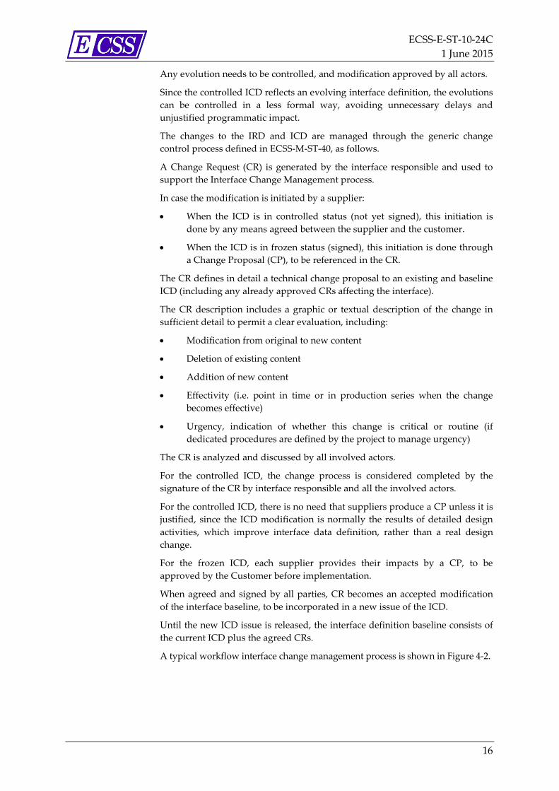
4.3.1 Generic interface management life cycle Figure 4-3 shows a generic life cycle referred to a typical interface involving customer and two suppliers.
NOTE In case more than two levels of customer/supplier are involved, this process is repeated recursively by each actor at each level of the customer/supplier chain.
This life cycle applies to product categories C and D as defined in ECSS-E-ST-10-02 Table 5-1.
The life cycle starts with the identification of the interfaces by the customer (typically between customer SRR and PDR).
After Customer PDR, the Interfaces Requirements applicable to Suppliers are identified and specified by the customer either in a self-standing IRD or embedded in a technical specification applicable to supplier, prior to suppliers’ contract start.
After the supplier's requirements are baselined, the customer establishes the preliminary interface definition, circulating it among the involved actors.
18
ECSS-E-ST-10-24C 1 June 2015
The suppliers provide IDDs and relevant technical design data.
The preliminary ICD is consolidated, formally issued and becomes the controlled ICD for Suppliers’ PDR.
After this stage, changes of the controlled ICD are possible in accordance with the simplified interface control process defined in clause 5.5.
Prior to the Suppliers’ CDRs, under the responsibility of the customer, suppliers and customer consolidate the controlled ICDs to become frozen, and approved by all parties
The approved frozen ICD is considered the final ICD, ready to permit the suppliers to start manufacturing, integration, implementation, or verification activities.
After reaching this stage, changes of the frozen ICD are possible in accordance with the interface control process defined in clause 5.5.
Figure 4-3: Generic interface management life cycle
19

ECSS-E-ST-10-24C 1 June 2015
4.3.2 Space element – Launch segment interface management life cycle
Figure 4-4 shows a life cycle referred to a typical Space to Launch segment interface life cycle.
The life cycle starts with the selection of the launcher by the space segment responsible, on the basis of available user manuals.
NOTE The user manual specifies the minimum duration between kick-off of launcher contract and launch.
After launcher contract kick-off meeting, the space segment responsible, taking into account the boundary conditions specified by the launcher user manual, prepares an IRD that contains:
• the mission requirements as specified by the space segment responsible,
• the interface definition and constraint coming from the space segment element supplier through the IDD.
On the above data, the launch segment service supplier establishes the preliminary interface definition (Issue 0 of ICD), circulating it among the involved actors.
The preliminary ICD is consolidated, formally issued and becomes the controlled ICD Issue 1 as result of the Preliminary Mission Analysis Review (PMAR).
As results of the Final Mission Analysis Review, the controlled ICD will become the frozen version for flight, approved by all parties.
Figure 4-4: Typical space to launch segment interface life cycle
20
ECSS-E-ST-10-24C 1 June 2015
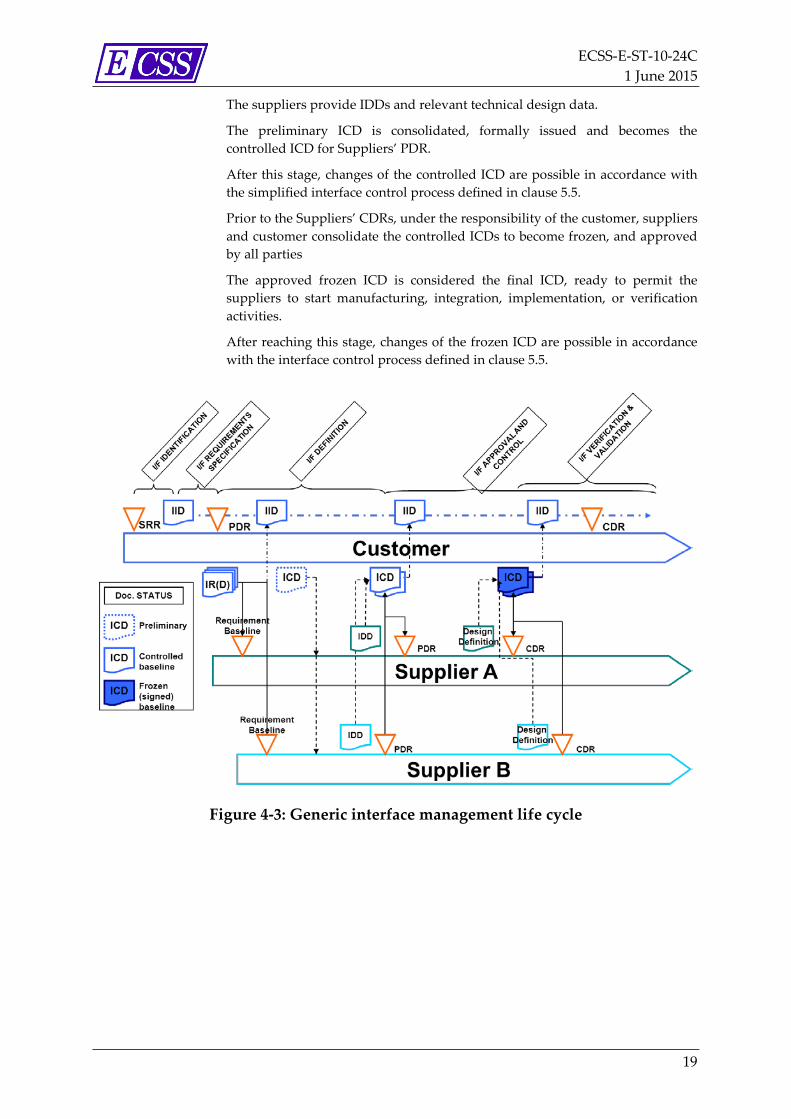
4.3.3 Space segment - Ground segment interface management life cycle
Figure 4-5 shows a life cycle referred to a typical interface involving space segment and ground segment.
The life cycle starts with the identification of the interfaces by the space system responsible (typically between space system SRR and PDR).
The Interfaces Requirements applicable to space segment - ground segment interface are identified and specified by the space system responsible. either in a self-standing IRD or embedded in a specification.
After the interface requirements are baselined, the space system responsible establishes the preliminary interface definition, circulating it among the involved actors.
The segments responsibles provide IDDs and relevant technical design data.
The preliminary ICD is consolidated, formally issued and becomes the controlled ICD for ground and space segment PDRs.
After this stage, changes of the controlled ICD are possible in accordance with the simplified interface control process defined in clause 5.5.
Prior to the ground and space segments CDRs, under the responsibility of the space system responsible, the controlled ICDs is consolidated to become frozen, and approved by all parties.
The approved frozen ICD is considered the final ICD, ready to permit the segments suppliers to start manufacturing, integration, implementation, or verification activities.
After reaching this stage, changes of the frozen ICD are possible in accordance with the interface control process defined in clause 5.5.
Figure 4-5: Typical space to ground segment interface life cycle
21
ECSS-E-ST-10-24C 1 June 2015
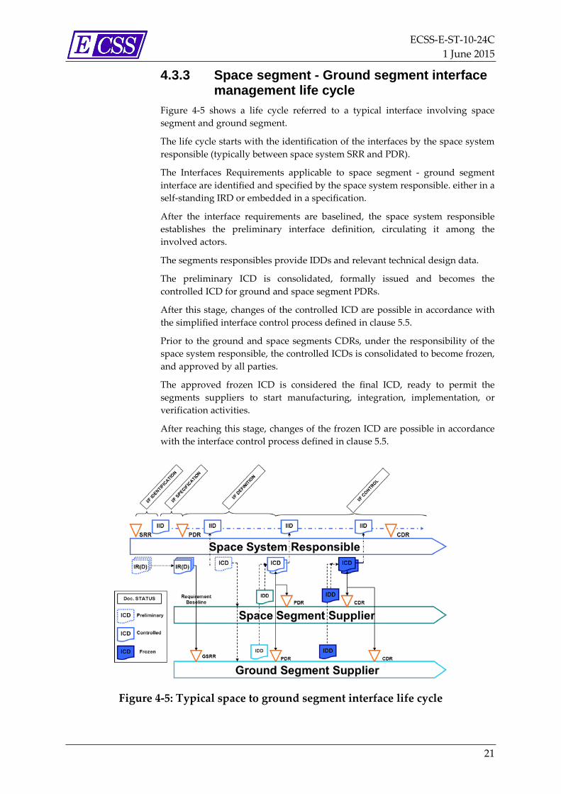
4.3.4 Interface management life cycle involving OTS products
Figure 4-6 shows the life cycle of an interface involving a category A or B off-the-shelf product and a category C or D product. Refer to ECSS-E-ST-10-02 Table 5-1 for the definition of the product categories.
The life cycle starts with the identification of the interfaces by the customer (typically between customer SRR and PDR) and the selection of the off-the-shelf product.
At the Equipment Qualification Status Review (EQSR), the interface end definition of the off-the-shelf product is captured in the off-the-shelf product IDD. The IDD will be then incorporated into the IRD and ICD.
For the item interfacing with the off-the-shelf product, the generic process of clause 4.3.1 applies, ensuring no modification of off-the-shelf product interface definition.
At the CDR of the item interfacing with the off-the-shelf product, the approved frozen ICD is considered the final ICD, ready to permit suppliers to start manufacturing, integration, implementation, or verification activities.
After reaching this stage, changes of the frozen ICD are possible in accordance with the interface control process defined in clause 5.5.
Figure 4-6: Typical interface management life cycle involving OTS
22
ECSS-E-ST-10-24C 1 June 2015
5 Requirements
5.1 Interface management planning a. An interface management plan shall be established by the interface
responsible to describe the Interface Management approach.
b. The interface management plan may be part of the Project Management Plan (ECSS-M-ST-10 Annex A) or part of the System Engineering Plan (ECSS-E-ST-10 Annex D) or a self-standing document, subject to agreement between the interface responsible and its customer.
NOTE The chosen approach depends on the complexity of the project.
c. The interface management plan shall define the applicability of this standard.
d. The interface management plan shall define tailoring and adaptation of this standard to Project needs and life cycle.
NOTE While interface management steps are mandatory, the way in which each step is documented can be tailored according to the rules defined in each clause of this standard.
e. The interface management plan shall define at least the:
1. applicability domain,
2. management logic,
3. responsibility and approval authorities,
4. interface consolidation approach and life cycle,
5. schedule,
6. documentation tree,
7. internal documentation organization approach (contractual, discipline or product decomposition), and
8. change management approach.
5.2 Interface identification a. The supplier shall list all the interfaces involved within his product.
b. The interfaces list of 5.2a shall include:
1. all interfaces crossing contractual boundaries,
23
ECSS-E-ST-10-24C 1 June 2015
2. any interface identified by the customer. NOTE Criteria used by the customer to identify
additional interface to be managed within the supplier product, are for example reuse, technical risk, criticality.
c. For each interface identified in the list of 5.2b, the following shall be provided:
1. involved interface ends,
2. contractual responsibilities,
3. technical documentation and their version specifying and defining the interface.
d. The information in the list of 5.2b, shall be updated and distributed to the involved actors every time that any applicable document is updated or a baseline established.
NOTE This interface information can be in the form of an Interface Identification Document (IID), as defined in Annex D.
5.3 Interface requirements specification a. The customer shall define the interface requirements in conformance
with the IRD DRD in Annex A. NOTE 1 Information regarding the expected delivery of
the document for each project review is provided in Annex A of ECSS-E-ST-10.
NOTE 2 As indicated in DRD Annex A, the IRD content can be merged together with Technical Specification.
b. The complete set of interface requirements shall be specified by the customer prior to the start of the supplier’s contract.
c. The precedence of the IRD with respect to other project documents shall be defined.
d. Suppliers shall provide their compliance status to the interface requirements.
e. Nonconformance to interface requirements shall be treated as major NCR in accordance with the NCR process as defined in ECSS-Q-ST-10-09.
5.4 Interface definition a. The interface responsible shall perform the following tasks:
1. collection of interface end data from involved actors;
2. sharing of interface data with involved actors;
3. coordination of the interface definition compliance with respect to interface requirements of clause 5.3;
24
ECSS-E-ST-10-24C 1 June 2015
4. checking of interface end data from suppliers, for:
(a) consistency,
(b) mutual compatibility.
5. baselining of the interface definition;
6. communicating interface changes among involved actors.
b. The actors shall be responsible of the interface end, by means of:
1. contributing to interface definition, providing an IDD, an one-end ICD, or relevant technical design data, in conformance with the IDD DRD in Annex C;
2. supporting the iterations of the interface definition, in order to achieve an agreed baseline;
3. ensuring interface end compatibility with respect to:
(a) interface requirement,
(b) interface definition.
c. For each identified and specified interface, the interface responsible with the contribution of the involved actors shall define interface characteristics in terms of:
1. interface plane definition;
2. interface behaviour identification;
3. data affecting the interface definition. NOTE 1 Examples for 5.4c.1 are: mounting surface
(between hardware products), Application Program Interface (between software products), communication network (between data systems).
NOTE 2 Examples for 5.4c.2 are: static, dynamic, nominal/off nominal, "state machine".
NOTE 3 Examples for 5.4c.3 are: dimensions, tolerances, coordinates, voltage, data format, temperature, load, heat flow, material, surface treatment, external standard reference.
d. To define the interfaces, the interface responsible shall provide an ICD in conformance with the ICD DRD in Annex B.
e. The ICD shall be put under configuration control prior to interface end suppliers PDR.
f. Nonconformance to ICD shall be treated as major NCR in accordance with the NCR process as defined in ECSS-Q-ST-10-09.
25

ECSS-E-ST-10-24C 1 June 2015
5.5 Interface control and approval a. Modifications to an ICD shall be managed in conformance with ECSS-M-
ST-40, adapting the process as defined in Clause 4.2.6.
b. The interface responsible shall communicate the approval or non-approval of an interface definition change with a rationale to all the actors.
c. The interface definition change shall be managed through a CR.
d. The CR shall be agreed and signed by each of the actors and by the interface responsible before it becomes applicable for implementation.
e. The interface definition agreed change shall be listed, until relevant CR content is incorporated in a new version of a baseline ICD.
NOTE Interface definition agreed change is as documented in the agreed CR.
f. The ICD shall be consolidated to the frozen status, prior to the CDR of the first product involved in the interface.
g. The frozen ICD shall be approved (signed) by all involved parties.
5.6 Interface verification and validation a. Interface requirement verification shall be performed in conformance
with ECSS-E-ST-10-02.
b. The approach for verifying interfaces shall be defined by the customer, identifying the type and method of verification activity.
NOTE One of the following types of verification, or a combination: • Stand-alone verification activity under
supplier responsibility. • Joint verification activity, performed under
customer responsibility with supplier support.
c. The customer shall define the supplier support needed for any joint verification activity.
d. Any stand-alone verification shall be completed successfully prior to the joint verification applicable to the same interface.
e. The customer and the suppliers shall agree whether interface validation is included or not.
f. If validation is included, the customer and suppliers shall agree on the interface validation approach.
26
ECSS-E-ST-10-24C 1 June 2015
Annex A (normative) Interface Requirements Document (IRD) -
DRD
A.1 DRD identification
A.1.1 Requirement identification and source document This DRD is called from ECSS-E-ST-10-24, requirement 5.3a.
A.1.2 Purpose and objective For a product, the interface requirements document (IRD) is a specific type of technical requirements specification that defines the requirements for an interface or a collection of interfaces.
The IRD is a document either included in or called up by a technical requirements specification (TS) as defined in ECSS-E-ST-10-06.
A.2 Expected response
A.2.1 Scope and content
<1> Introduction
a. The IRD shall contain a description of the purpose, objective, content and the reason prompting its preparation.
<2> Applicable and reference documents
a. The IRD shall list the applicable and reference documents in support to the generation of the document.
b. The relationship and precedence of the IRD to other project documents shall be clearly defined.
c. The IRD shall include the following references:
1. Product tree (as defined in ECSS-M-ST-10 Annex B),
2. Specification tree (as defined in ECSS-E-ST-10),
27
ECSS-E-ST-10-24C 1 June 2015
3. References to requirements specified in other Technical requirement specifications or Standards which are applicable for a particular Interface.
NOTE For example, an IRD can refer to individual requirements coming from Technical Requirement Specification such as GDIR (General Design and Interface Requirements) or SSS (System Support Specification) or Standards such as MIL-STD-1553 Bus.
d. It shall be confirmed that the IRD does not include duplicate or conflicting requirements already specified in another Technical requirements specification applicable to any interface end.
<3> Definition of terms and abbreviated terms
a. The applicable dictionary or glossary and the meaning of specific terms or abbreviation utilized in IRD shall be defined.
<4> Interface requirements
a. The IRD shall define the physical, functional, procedural and operational interface requirements between two or more items in the product tree and ensure hardware and software compatibility.
NOTE Interface requirements include for example, physical measures, definitions of sequences, of energy or information transfer, design constraints, and all other significant interactions between items.
b. Interface Requirements shall be specified in accordance with ECSS-E-ST-10-06.
c. Each interface requirements shall be accompanied by its verification requirements.
d. For each verification requirement as defined in A.2.1<4>c., the verification responsibility shall be defined.
NOTE This can be joint responsibility, stand-alone responsibility or any combination of them.
e. The IRD shall specify the requirements of an interface, for all identified interface ends.
f. The IRD shall specify for each requirement the applicability to each interface end.
g. In case of an existing interface end design, the interface requirements shall address:
1. interface plane definition,
2. interface behaviour definition,
3. data affecting the interface definition.
28

ECSS-E-ST-10-24C 1 June 2015
h. In addition to the general requirements defined in ECSS-E-ST-10-06, for each interface requirement the applicability to each interface end shall be specified.
i. In case the IRD addresses more than one interface, the interface requirements shall be grouped either by interface end pair, by nature of interface, or by contractual party.
NOTE An example of grouping by nature of interface is arranging the requirements by discipline such as mechanical, electrical, thermal and software/data. See also Annex E.
<5> Items to be addressed a. For each interface, the following aspects shall be addressed:
1. interface description using tables, figures, or drawings,
2. units of measure including scale of measure,
3. tolerances or required accuracies,
4. in case of using non-SI quantities or units, conversions and conventions,
5. interface plane specification,
6. coordinate system specification, in case of interfaces involving geometric aspects,
7. interface behaviour specification, including limitation of use. NOTE 1 Example of interface plane is the separation
plane between launch adapter and spacecraft. NOTE 2 Example of limitation of use is decrease in
capability.
b. Interface requirements shall be built starting from the Reference Interface Data List of Annex E and adding all data necessary to specify the interface.
NOTE It is good practice to group the interface requirements by the interface natures as defined in Annex E.
A.2.2 Special remarks a. The content of the IRD may be merged with the content of the technical
requirements specification (as defined in ECSS-E-ST-10-06 Annex A) of the product.
29
ECSS-E-ST-10-24C 1 June 2015
Annex B (normative) Interface Control Document (ICD) – DRD
B.1 DRD identification
B.1.1 Requirement identification and source document This DRD is called from ECSS-E-ST-10-24, requirement 5.4d.
B.1.2 Purpose and objective The purpose of the ICD is to define the design of the interface(s) ensuring compatibility among involved interface ends by documenting form, fit, and function.
The Interface Control Document (ICD) can be, either: • a single self-standing document defining the interface. • a single document, referencing other documents (e.g. IDD, single-end
ICD, interface drawings), which define separately the involved interface ends.
• a single document, annexing a set of IDDs (or single-end ICDs), made integrally and jointly applicable to all the involved interface ends. In this case, the entire set of documents (issued by the suppliers, coordinated by the customer and approved by all the involved actors) is integrally and jointly controlling the interface: therefore, the rules and requirement hereafter specified are intended to be applicable either to the single ICD or jointly to the entire set of documents, depending on the selected approach.
The ICD is managed by the customer (or his delegate) and concurred by all the involved actors.
The ICD is used:
1. to document the interface definition,
2. to control the evolution of the interface,
3. to document the design solutions to be adhered to, for a particular interface,
4. as one of the means to ensure that the supplier design (and subsequent implementation) are consistent with the interface requirements,
5. as one of the means to ensure that the designs (and subsequent implementation) of the participating interface ends are compatible.
30

ECSS-E-ST-10-24C 1 June 2015
B.2 Expected response
B.2.1 Scope and content
<1> Introduction
a. The ICD shall contain a description of the purpose, objective, content and the reason prompting its preparation.
<2> Responsibility
a. The responsibilities of the interfacing organizations for development of the ICD shall be stated.
b. The document approval authority (including change approval authority) shall be defined.
c. The interface ends responsible shall be stated.
<3> Applicable and reference documents
a. The ICD shall list the applicable and reference documents and standards in support to the generation of the document.
b. The relationship and precedence of the ICD to other programme documents shall be clearly defined.
c. The ICD shall include the following references:
1. Product tree (as defined in ECSS-M-ST-10 Annex B),
2. Specification tree (as defined in ECSS-E-ST-10).
<4> Definition of terms and abbreviated terms a. The applicable dictionary or glossary and the meaning of specific terms
or abbreviation utilized in ICD shall be defined.
<5> Interface definition
a. The interface responsible shall establish a complete and exhaustive list of technical characteristics of the interface to be reflected in the interface definition/data.
NOTE Informative Annex E lists a number of example aspects to be considered in interface definition. The list is meant to be used as a starting point but cannot be considered exhaustive.
b. For each identified and specified interface, the interface responsible accounting for the contribution of the involved actors shall define interface characteristics in terms of:
1. interface plane definition,
2. interface behaviour identification, including limitation of use,
31

ECSS-E-ST-10-24C 1 June 2015
3. interface description using tables, figures, drawings, models, data base as appropriate,
4. data affecting the interface definition,
5. units of measure including scale of measure,
6. tolerances or required accuracies,
7. in case of using non-SI quantities or units, conversions and conversions.
NOTE 1 Examples for item 1 are: mounting surface (between hardware products), Application Program Interface (between software products), communication network (between data systems).
NOTE 2 Examples for item 2 are: static, dynamic, nominal/off nominal, state machine. Possible limitation of use is coming from a decrease of capability.
NOTE 3 Example of item 3 are: mechanical drawing, interface 3D CAD model, electrical circuit schematic, software API, software architectural or detailed design document.
NOTE 4 Examples for item 4 are: dimensions, tolerances, coordinates, voltage, data format, temperature, load, heat flow, material, surface treatment, external standard reference.
c. The ICD shall detail the interface definition between two (or more) interface ends.
d. The ICD shall be grouped by contractual, discipline or product decomposition (product tree).
e. Each ICD version shall identify the incorporated approved CR.
f. The interface definitions shall be grouped per pair of interface ends having a common interface plane.
g. In case the ICD addresses more than one interface, the interface definition shall be grouped either per physical/logical interface, or per nature of interface.
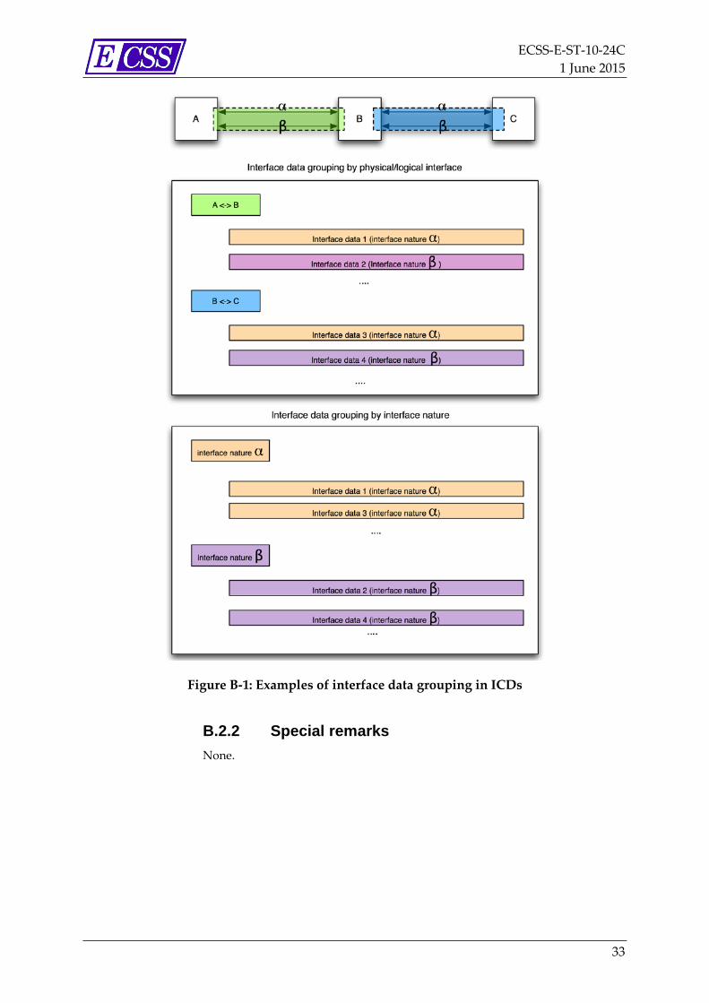
NOTE 1 An example of physical/logical grouping is arranging the interface data by a pair of interface ends (see Figure B-1).
NOTE 2 An example of grouping by nature is arranging the interface data by discipline such as mechanical, electrical, thermal and software/data (see Figure B-1).
NOTE 3 It is a good practice to group the interface requirements by the interface natures defined in Annex E.
32
ECSS-E-ST-10-24C 1 June 2015
Figure B-1: Examples of interface data grouping in ICDs
B.2.2 Special remarks None.
33

ECSS-E-ST-10-24C 1 June 2015
Annex C (normative) Interface Definition Document (IDD) or
Single-end Interface Control Document – DRD
C.1 DRD identification
C.1.1 Requirement identification and source document This DRD is called from ECSS-E-ST-10-24, requirement 5.4b.1.
The supplier of an interface end is responsible for the associated IDD.
C.1.2 Purpose and objective The purpose of the IDD is to document the current design of an interface end.
NOTE 1 Often, the IDD is called “Single-end ICD”. In such case, there is no need to change the name of this document.
NOTE 2 The ”Single-end ICD” is sometimes referred as “unit ICD” or “equipment ICD”.
NOTE 3 When interface is controlled by a set of IDDs/Single-end ICDs, it is suggested if possible, to change the name of IDD in “Single-end ICD” at interface baselining.
The IDD is a unilateral document issued and controlled by the interface end supplier.
The IDD is used:
a. to document the interface end definition,
b. to control the evolution of the interface end,
c. to document the design solutions to be adhered to, for a particular interface end,
d. as one of the means to ensure that the supplier design (and subsequent implementation) are consistent with the interface requirements and interface definition,
e. as one of the means to ensure that the designs (and subsequent implementation) of the participating interface ends are compatible.
34
ECSS-E-ST-10-24C 1 June 2015
C.2 Expected response
C.2.1 Scope and content
<1> Introduction
a. The IDD shall contain a description of the purpose, objective, content and the reason prompting its preparation.
<2> Responsibility
a. The IDD shall be issued and controlled by the interface end supplier.
b. The document approval authority (including change approval authority) shall be defined.
<3> Applicable and reference documents
a. The IDD shall list the applicable and reference documents and standards in support to the generation of the document.
b. The relationship and precedence of the IDD to other programme documents shall be clearly defined.
<4> Definition of terms and abbreviated terms
a. The applicable dictionary or glossary and the meaning of specific terms or abbreviation utilized in IDD shall be defined.
<5> Interface end definition
a. The IDD shall contain:
1. interface end description and data definition using tables, figures, drawings, models, data base as appropriate,
2. units of measure including scale of measure,
3. tolerances or required accuracies,
4. in case of using non-SI quantities or units, conversions and conventions,
5. interface plane implementation,
6. interface end behaviour,
7. interface end data.
b. Interface end data shall be built starting from the Reference Interface Data List of Annex E and further identify all data necessary to document the design of the interface end.
NOTE It is recommended to group the interface end data by the interface natures defined in Annex E.
35
ECSS-E-ST-10-24C 1 June 2015
C.2.2 Special remarks
<1> Form
a. The IDD may take different forms depending on the kind of interface end it documents.
NOTE Examples of different forms are: a mechanical drawing, interface 3D CAD model, electrical circuit schematic, software API, software architectural or detailed design document.
b. The IDD may be a container with unambiguous references into the supplier's Design Definition File (DDF).
NOTE IDD covers the formerly called "interface inputs" from the supplier to the customer.
36
ECSS-E-ST-10-24C 1 June 2015
Annex D (informative) Proposed content of an "Interface
Identification Document (IID)"
D.1 Purpose and objective The interface identification document (IID), as proposed by the Note of requirement 5.2d, contains the index of all identified interfaces.
For completeness, the IID also list the external interfaces.
For each interface the IID lists the references to the applicable IRD, IDD, ICD and change requests, including version and responsible for each document
The IID also lists reference to any standard that is applicable for all interfaces it describes.
D.2 Scope and content
D.2.1 Introduction • The IID describes the purpose, objective, content and the reason
prompting its preparation.
• The IID describes/illustrates the interface context at the appropriate decomposition level, i.e. showing the items being interfaced, by referencing the applicable Product and architecture documentation or including a context interface diagram.
D.2.2 Applicable and reference documents a. The IID lists the applicable and reference documents in support to the
generation of the document.
b. The IID includes the following references:
1. Product tree (as defined in ECSS-M-ST-10 Annex B),
2. Standards applicable (e.g. ECSS, CCSDS, Project defined standards).
37

ECSS-E-ST-10-24C 1 June 2015
D.2.3 Interface list a. The identified interfaces are listed as a series of interface records.
b. Each interface record contains as a minimum the following fields:
1. unique interface identifier,
2. reference to the participating interface ends,
3. interface responsible,
4. interface actors responsible of each interface end,
5. references to applicable documents, i.e. interface requirements baseline, ICD, IDD, CR, which defines the baseline of the interface addressed in the record.
NOTE 1 Initially, the list of references can be empty. It will be populated over the life cycle of the interface.
NOTE 2 Use specific references, i.e. include document identifier, version identifier, relevant section number.
D.3 Special remarks The IID is intended to be a living document that is actively maintained to be up-to-date for the duration of a programme or project. Therefore the IID can be implemented in the form of a web / database application.
The interface records can be grouped by discipline, by contract or WBS element or by item within the product tree.
Examples for interface record are:
Grouped by item within the product tree:
• Mission Control System <-> Ground Station • Space Segment <-> Mission Control Centre • XB Antenna Adapter <-> Platform • Payload <-> EGSE • UNIT 1 <-> UNIT 2 Grouped by discipline: • UNIT 1 <-> UNIT 2 Electrical Interface Signalling • UNIT 1 <-> UNIT 2 Electrical Interface Power Supply • UNIT 1 <-> UNIT 2 Mechanical Interface • UNIT 1 <-> UNIT 2 Data Interface Commanding • UNIT 1 <-> UNIT 2 Data Interface Telemetry
Grouped by contract or WBS element: • UNIT 1 <-> UNIT 2 Company 1 Interface (electrical, mechanical) • UNIT 1 <-> UNIT 2 Company 2 Interface (data)
38
ECSS-E-ST-10-24C 1 June 2015
Annex E (informative) Reference interface data list
E.1 Introduction This annex describes the reference list of interface data to take into account when creating or updating an IRD, ICD or IDD.
As it is impossible to produce an exhaustive list that is valid for any space project, this list can be used as a reference and starting point and is by definition not exhaustive. However where applicable it is good practice to use the terms and grouping of this list, in order to promote the uniformity of interface specifications and definitions.
The reference list of interface data is described in this annex at two levels:
• Clause E.2 contains interface data characterization and the description of the list, identifying the interface natures and the ECSS disciplines to which they belong.
• Clause E.3 expands this information, listing the interface data, grouped by natures as identified in clause E.2.
This annex has been built to have data relevant listed under the header of the discipline but avoiding as much as possible repetition of data (e.g. geometry is listed under mechanical but is needed for many other disciplines). Being listed under one discipline does not exclude the relevance of the data for other disciplines.
E.2 Interface nature and data characterisation
E.2.1 Interface nature The interface data are grouped by interface nature, with further hierarchical decomposition into subgroups of related data where deemed useful.
The nature of an interface designates a grouping of related interface data, typically in an engineering discipline oriented way.
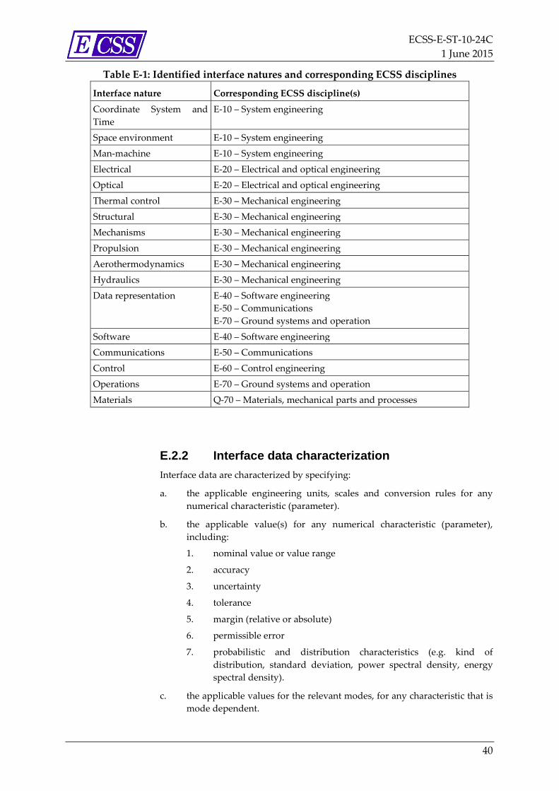
Table E-1 lists the identified interface natures. The order follows the numbering of the main ECSS discipline.
39
ECSS-E-ST-10-24C 1 June 2015
Table E-1: Identified interface natures and corresponding ECSS disciplines
Interface nature Corresponding ECSS discipline(s)
Coordinate System and Time
E-10 – System engineering
Space environment E-10 – System engineering
Man-machine E-10 – System engineering
Electrical E-20 – Electrical and optical engineering
Optical E-20 – Electrical and optical engineering
Thermal control E-30 – Mechanical engineering
Structural E-30 – Mechanical engineering
Mechanisms E-30 – Mechanical engineering
Propulsion E-30 – Mechanical engineering
Aerothermodynamics E-30 – Mechanical engineering
Hydraulics E-30 – Mechanical engineering
Data representation E-40 – Software engineering E-50 – Communications E-70 – Ground systems and operation
Software E-40 – Software engineering
Communications E-50 – Communications
Control E-60 – Control engineering
Operations E-70 – Ground systems and operation
Materials Q-70 – Materials, mechanical parts and processes
E.2.2 Interface data characterization Interface data are characterized by specifying:
a. the applicable engineering units, scales and conversion rules for any numerical characteristic (parameter).
b. the applicable value(s) for any numerical characteristic (parameter), including:
1. nominal value or value range
2. accuracy
3. uncertainty
4. tolerance
5. margin (relative or absolute)
6. permissible error
7. probabilistic and distribution characteristics (e.g. kind of distribution, standard deviation, power spectral density, energy spectral density).
c. the applicable values for the relevant modes, for any characteristic that is mode dependent.
40

ECSS-E-ST-10-24C 1 June 2015
E.3 Interface data list
E.3.1 Coordinate system and time a. Coordinate system (see ECSS-E-ST-10-09 for details):
1. Inertial Coordinate Systems
2. Orbital Coordinate Systems
3. Launcher Coordinate Systems
4. Satellite-fixed Coordinate System (generic platform and payload)
5. Body-fixed Rotation (planet) Coordinate Systems
6. Topocentric Coordinate Systems
7. Test facility Coordinate Systems
8. Simulator Coordinate Systems
9. Processing / Product Coordinate Systems (e.g. equipment, unit, sub assembly, part).
b. Euler angle definition (see ECSS-E-ST-10-09 for details).
c. Attitude quaternion convention (see ECSS-E-ST-10-09 for details).
d. Time reference:
1. Reference
2. Format
3. Adjustment update and reset
4. Relationship with external time sources
5. Relationship between time systems.
E.3.2 Space environment a. Particle radiation fluxes:
1. Mission average electron energy spectrum
2. Mission average proton energy spectrum
3. Solar proton fluence spectrum
4. Peak electron energy spectrum
5. Peak proton energy spectrum
6. Peak solar proton flux spectrum.
b. Mission dose-depth curve:
1. Ionising dose
2. Non-ionising dose
3. Effective dose equivalent (radiobiological).
c. LET spectra
d. Damage-equivalent fluences for solar cells
41

ECSS-E-ST-10-24C 1 June 2015
e. Plasma environment:
1. Worst-case surface charging environment (bi-maxwellian temperatures and densities)
2. Mean plasma environment
3. Cold plasma density, temperature, composition, relative velocity (high-voltage interactions and ram-wake effects).
f. Micro-particle environment (size and velocity distribution):
1. Micro-debris (non-trackable population)
2. Micrometeoroids.
g. Planetary magnetic field:
1. Mean field strength, direction
2. Short term variations and activity indices.
h. Solar activity:
1. Solar irradiance spectrum (including UV)
2. Activity indices (F10.7, Sunspot number)
3. Minimum, mean and maximum constant values for short and long periods
4. Reference values over one solar cycle.
i. Earth atmosphere:
1. Total and constituent (e.g. atomic oxygen) densities for minimum, mean and maximum solar and geomagnetic activity
2. Composition for minimum, mean and maximum solar and geomagnetic activity.
j. Planetary atmosphere:
1. Climate database (global distributions of atmospheric parameters).
k. Induced permanent deposit.
l. Contamination from purge.
m. Solar panels contamination.
n. Droplets contamination.
E.3.3 Man-machine a. Anthropometry and bio-mechanics:
1. Body size
2. Joint Motion
3. Reach
4. Neutral Body Posture
5. Body Surface Area
6. Body Volume
7. Body Mass Properties
8. Strength.
42
ECSS-E-ST-10-24C 1 June 2015
b. Sensation and perception:
1. Vision
2. Auditory System
3. Olfaction and Taste
4. Vestibular system
5. Kinaesthesia
6. Reaction Time
7. Coordination.
c. Environment:
1. Atmosphere
2. Microgravity
3. Acceleration
4. Acoustics
5. Vibration
6. Radiation
7. Thermal Environment.
d. Human-computer interface:
1. Data Display
2. Text
3. Tables
4. Graphics
5. Coding
6. Window Displays
7. Format Design
8. Information Display Rate
9. User Computer Dialogues
10. Movement within User Interfaces
11. Manipulating Data
12. User Guidance.
E.3.4 Electrical a. Power interface data:
1. Power consumption
2. Input and Output Power interfaces:
(a) Minimum / maximum voltage
(b) Impedance
(c) Undervoltage switch-off
(d) Overvoltage protection
(e) Output voltage on/off time (rise/fall time)
43
ECSS-E-ST-10-24C 1 June 2015
(f) Current (maximum operating, inrush, inrush duration, current rate of change)
(g) Over-current protection (type, nominal current, current limitation and duration)
(h) Drop-out limits.
b. Grounding and insulation:
1. Grounding concept
2. Internal grounding diagram
3. Insulation.
c. Signal interface data:
1. Signal type (e.g. analogue, discrete, bi-level, multi-level)
2. Signal function (e.g. command, measurement, status, clock)
3. Circuit diagram / signal level diagram
4. Electrical characteristics (depending on the technology, e.g. static, dynamic and protection):
(a) Signal characteristics
(b) Signalling system (e.g. single ended, differential)
(c) Signal transfer (e.g. DC-coupled)
(d) Signal level (interface voltage low / high)
(e) Transfer function for analogue signal
(f) Interface resistance (open / closed condition)
(g) Logical representation (e.g.: 0 = low = false; 1 = high = true)
(h) Driving capability
(i) Operating current
(j) Minimum open circuit voltage
(k) Impedance (line-line)
(l) Ripple and signal-to-noise ratio
(m) Common mode voltage (CMV, CMRR)
(n) Overvoltage protection
(o) Fault voltage emission
(p) Fault current emission
(q) Current limitation
(r) DC isolation (to structure)
(s) Interface behaviour specifics in OFF condition.
d. Harness interfaces:
1. Connector interface data – per connector:
(a) Specific requirements or remarks
(b) Identifier (Jxx / Pxx)
(c) Function
(d) Part number
44
ECSS-E-ST-10-24C 1 June 2015
(e) Coding (e.g. key, colour)
(f) Number of pins
(g) Gender (male/female)
(h) Specification
(i) Lockers /Backshell part number and material.
2. Connector interface data – per pin:
(a) Pin number
(b) Component type / specification
(c) Function
(d) Polarity (P = plus, M = minus, R = reversible).
3. Wiring:
(a) Type of cable (e.g. single wire, twisted shielded pair, coax)
(b) Wire gauge
(c) Insulation
(d) Shielding / grounding
(e) Impedance
(f) Maximum/minimum cable length
(g) Coding (e.g. colour).
4. Bundle:
(a) Composition
(b) Protection/Coating/Shielding
(c) Coding
(d) Constraint (e.g. minimum bending radius, maximum unsupported length).
e. Telemetry / telecommand list and description.
f. Data bus interface:
1. Physical interface:
(a) Standard interface (e.g. Mil-1553-STD, Spacewire, EIA485)
(b) Detailed description.
2. Data interface:
(a) Data bus architecture (star or bus topology)
(b) Coding (encoding, decoding)
(c) Bit rate / data rate
(d) Bit error rate
(e) Data protocol / structure / framing (e.g. address, data fields, checksum)
(f) Word length (number of bits per word)
(g) First bit in transfer (MSB, LSB)
(h) Data packet description
(i) Signal / data representation
45

ECSS-E-ST-10-24C 1 June 2015
(j) Communication / data traffic rules (master / slave, broadcast messages, acknowledgement of receipt)
(k) Synchronisation (synchronous / asynchronous data transfer)
(l) Timing
(m) Start / end delimiters
(n) Response time
(o) Jitter
(p) Error handling
(q) Bus protocol (e.g. Ethernet, CCSDS).
E.3.5 Optical a. Optical characteristics of surfaces (e.g. body, solar arrays, radiators, MLI,
coatings lenses, windows):
1. Reflectivity
2. Absorptivity
3. Emissivity
4. Transmissivity
5. Specularity
6. Brightness definition, coefficients.
b. Spectrum (band centre, bandwidth, distribution)
c. Light sources
d. Reflectors
e. Video target (layout, characteristics)
f. Optical sensors passive or active (layout, characteristics, field of view)
g. Coatings and surface finishes
h. Ranging cues (layout, characteristics)
E.3.6 Thermal control a. Baseplate thermal contact area
b. Special thermal mounting constraints (e.g. thermal fillers, washers, thermal insulation)
c. Heat transfer mode / environment (conduction, radiation, convection)
d. Temperature reference point(s)
e. Temperature range for each mode (e.g. operational, non-operational, storage, transport), and minimum switch-on temperature
f. Temperature stability at temperature reference point(s)
g. Thermal gradients
h. Heat capacity
46
ECSS-E-ST-10-24C 1 June 2015
i. Solar absorptance for exposed surfaces (BOL, EOL)
j. Infra-red emittance for surfaces (BOL, EOL)
k. Contact area coplanarity
l. Contact area flatness
m. Contact area roughness
n. Minimum, nominal, maximum dissipated power (e.g. from unit, from heater) and relevant time-profile for each phase/configuration/life condition (e.g. BOL, EOL)
o. Maximum power density (e.g. for heater, for heat pipes)
p. Authorized zones definition, external location for application of thermal hardware (e.g. MLI, heaters, thermostats, thermistors, Velcro)
q. Interface thermal mathematical models
r. Humidity and condensation (for Environmental Control and Life Support, materials and equipment)
s. Interface heat flux and heat flux limits at all thermal interfaces
E.3.7 Structural a. Reference coordinate system definition and reference hole
b. Envelope dimensions
c. Mass (nominal, uncertainty, dispersion)
d. Centre of gravity (nominal, uncertainty, dispersion)
e. Moments of inertia (nominal, uncertainty, dispersion)
f. Mounting hardware definition (standard)
g. Mounting holes size and location
h. Mounting pads thickness for screw length definition
i. Geometrical tolerances
j. Venting holes location
k. Special mounting and maintenance geometrical constraints
l. RF ports geometry
m. RF ports location and orientation
n. Connector locations
o. Torques applied
p. Recommended torque for mobile part
q. Bonding, grounding studs, type identification and fixing point location
r. Alignment devices location and definition
s. Adjustment and alignment information
t. Contact area materials, coatings and finishing
47
ECSS-E-ST-10-24C 1 June 2015
u. Contact surface flatness and roughness
v. External material and coating per zone
w. Interface description for special handling and installation
x. Pneumatic interface geometrical definition
y. Hydraulic interface geometrical definition
z. Configuration and layout (including stay-in and stay-out zones)
aa. Related loose parts (bolts, nuts, washers, …)
bb. Static loads, dynamic loads, shock, acoustic vibration
cc. Acoustic noise (frequency, spectrum, level)
dd. Interface mechanical mathematical models
E.3.8 Mechanisms a. Mobile parts and motion
b. Static geometrical envelopes (stowed and deployed)
c. Deployment envelope (kinematic)
d. Operational envelope
e. Lubrication
f. Design life (Sequence and timing, number of operations and activations)
E.3.9 Propulsion a. Propulsion overall:
1. Performance tables
2. Performances at the propulsion reference point
3. Nominal performance ranges for the pressure regulated domain
4. Global performance ranges for the whole nominal operating domain
5. Global performance ranges in off-nominal situation
6. Thrusters use limits
7. Modes
8. Monitoring
9. Operations
10. Propellant level
11. Propellant budget
b. Thrusters:
1. Maximum thrust
2. Minimum thrust
3. Utilization
4. Commanding
48
ECSS-E-ST-10-24C 1 June 2015
c. Induced plume environment:
1. Thrusters plume model
2. Thrusters configuration
3. Thrusters firing scenarios
4. Contamination
5. Pressure
E.3.10 Aerothermodynamics a. Reference surface
b. Time history of aerodynamics and aerothermodynamics databases variables and uncertainties
E.3.11 Hydraulics a. Geometrical definition (e.g. tube ends, flanges, holes)
b. Applicable fitting/disconnect standard PN
c. Fitting envelope constraints
d. Transported fluid
e. Filtration requirements
f. Other receive/supply fluid quality
g. Liquid/gas interface temperatures
h. Interface pressures
i. Interface flow rates
j. Allowed pressure drop/ required pressure rise
k. Contact area materials and finishing constraints
l. Allowed liquid/gas loop leakages
m. Loop isolation requirements
n. Liquid/gas exchange conditions
E.3.12 Data representation a. Data representation
b. Bit numbering
c. Endianness (big, little)
d. Data transmission ordering
e. Unused words and bits
f. Data types definition
49

ECSS-E-ST-10-24C 1 June 2015
E.3.13 Software a. Operating system
b. Operating hardware
c. Required software libraries
d. Required compiler, build environment
e. API definition (i.e. function prototype/signature, input/output parameter format and type, exceptions, not implemented/not allowed functionality, non-functional related effects, etc.)
f. Errors and warnings returned
g. Timing constraints
h. Shared memory location and content
i. Semaphores and locks
j. Memory map
k. Symbol map
l. Map of registers – including name, physical address and read/write instructions)
m. Map of inputs/outputs – including name, physical address and read/write instructions
n. List of interrupts
o. Telecommand interface and data
p. Telemetry interface and data
q. List of available services/functions
r. Thread-safe compliance
s. Memory load, dump and check procedures/services
t. Smallest addressable unit
E.3.14 Communications a. Radio frequency links:
1. Frequency,
2. Spectrum
3. Band
4. Transmitted (total) power
5. Noise spectral density
6. Receiver band sensitivity
7. Receiver allowed maximum input power in OFF condition
8. Gain
9. Radiation pattern
10. EIRP
50
ECSS-E-ST-10-24C 1 June 2015
11. Angular beam-width
12. Signal polarisation characteristics
13. Cross polarisation leakage
14. Attenuation
15. System noise temperature
16. Link budget
b. Modulation and coding of RF links:
1. Modulation (e.g. analogue, digital, FM, AM, Phase modulation: QPSK, 8PSK)
2. Channel encoding (e.g. block, convolutional)
3. Error correction (e.g. RS)
4. Scrambling (e.g. polynomial)
5. Interleaving
6. CADU structure (ASM, Codeblock)
c. Transfer and segmentation layer on space links:
1. Transfer frame format:
(a) Transfer Frame size
(b) Transfer frame header
(c) Transfer frame trailer
2. Virtual Channel list
3. Master Channel List
4. Multiplexing
5. Transfer frame error control
6. Segmentation
7. Idle frame
d. Space packet layer:
1. Space Packets Format:
(a) Packets size
(b) Packet header
(c) Data field header
2. APID list
3. Packet error control
4. Segmentation
5. Idle packet
6. Time formats specification
7. PUS Tailoring
8. Encryption
9. Encryption protocol management (e.g. keys management)
51
ECSS-E-ST-10-24C 1 June 2015
e. Commanding:
1. Use of BD/AD
2. Authentication
3. CCSDS packet acceptance and acknowledgement
4. Use of COP-1/FOP-1/FARM-1
5. Criticality
f. Bus link protocols:
1. Logical layer (message composition and format, time features of, response time, no-response time-out, word interface)
2. Synchronous Packet Transfer Layer (cycles, subframe time division for message transmission)
3. Transport of nominal CCSDS packets over busses
g. Discrete lines
h. Functional/Operational type of communication:
1. Commands (e.g. list, function)
2. Telemetry/housekeeping data (e.g. type, name, unit, identifier)
3. Synchronisation logic
i. Link control per type of communication (on/off)
j. Data interface data:
1. Type of exchange (e.g. physical media, network)
2. File format
3. File naming
4. Format validation (e.g. XML Schema)
5. Data encoding
6. Data encryption (e.g. type, key type, key length)
7. Frequency of transfer (e.g. daily, weekly, intermittent, 1 Hz)
8. Timeliness of the transfer
9. Transfer protocol (e.g. FTP, HTTP, TCP, RTSP)
10. Error handling
11. Clean-up policies (e.g. read and delete, read-only, delete and write)
12. Retention Time
13. Permission
14. Physical media (e.g. DVD, LTO4, Hexabyte, CD, Hard Disk)
15. Formatting of physical media (e.g. ISO, NTFS, Joliet, HFS+)
16. Labelling and indexing
17. Initiator of transfer
52

ECSS-E-ST-10-24C 1 June 2015
E.3.15 Control a. Reference guidance and navigation frame and attitude convention
b. Local orbital frame (TLOF)
E.3.16 Operations a. Schedule/process
b. Events
c. Operational scenarios (nominal, alternative, contingency)
d. Modes (e.g. nominal operational, standby, hibernations, safe)
e. Format of exchanged operation data (e.g. planning, instructions, requests, reports, acknowledgments, confirmations, alarms)
f. Actors (e.g. operator, operation engineer, operation manager)
g. Contact details (e.g. phone, e-mail, address)
E.3.17 Materials a. Material compatibility / constraints
b. Materials outgassing
c. Material Humidity
53

ECSS-E-ST-10-24C 1 June 2015
Bibliography
ECSS-S-ST-00 ECSS system – Description, implementation and general requirements
54