interim advice note 147/12 drainage surveys and data · interim advice note 147/12 drainage surveys...
TRANSCRIPT

Interim Advice Note 147/12 Drainage surveys and data
IAN 147/12 1 of 31 Jul 12
INTERIM ADVICE NOTE 147/12 Drainage surveys and data
Summary This interim advice note provides guidance on drainage surveys and associated data.
Instructions for Use This IAN takes immediate effect. It should be read in conjunction with HD 43/04 and SD 15/03.

Interim Advice Note 147/12 Drainage surveys and data
IAN 147/12 2 of 31 Jul 12
Table of Contents 1. Introduction.......................................................................................................................3 2. Drainage Surveys .............................................................................................................5 3. Drainage Drawings...........................................................................................................9 4. Asset Inventory Data ......................................................................................................11 5. Asset Condition Data......................................................................................................14 6. Detailed Defect Data ......................................................................................................15 7. Normative References....................................................................................................17 8. Informative references....................................................................................................17 9. User support ...................................................................................................................17 Annex A. Changes to, and guidance on, HD43/04 and SD15/03 ...................................18 Annex B: Amendments required to this IAN when used in projects carried out under English DBFO contracts 31 List of Tables Table 4-1: High level grouping of drainage asset types .........................................................12 Table 5-1: Structural and service grade definitions ................................................................14 Table 6-1: Structural and service grade calculation method ..................................................15 Table 6-2: Structural and service grade definitions ................................................................16 Table A-1: Summary of changes to HD43/04 and SD15/03...................................................19 Table A-2: List of other additional item types .........................................................................30 List of Figures Figure 1-1: Drainage asset management, surveys, data and HADDMS/IAM IS ....................4 Figure A-1: Incomplete inventory at extent of available records ...........................................21 Figure A-2: Incomplete inventory with phantom node ...........................................................21 Figure A-3: Incomplete inventory due to missing information ...............................................22 Figure A-4: Incomplete inventory with phantom connector ...................................................22 Figure A-5: Use of ghost nodes to connect gullies with carrier pipes (as previously
required in HD43/04) ..........................................................................................23 Figure A-6: Use of connector nodes and connectivity attributes to connect gullies and
carrier pipes........................................................................................................23 Figure A-7: Example of “over-the-edge” drainage.................................................................24 Figure A-8: Example of grip inlets without formal drainage...................................................25 Figure A-9: Example of grip inlets with formal drainage........................................................25 Figure A-10: Use of inlets, outlets and outfalls.......................................................................26 Figure A-11: Region nodes, region items and region connectors ..........................................29

Interim Advice Note 147/12 Drainage surveys and data
IAN 147/12 3 of 31 Jul 12
1. Introduction 1.1 This Interim Advice Note (IAN) introduces new, more cost effective methods of
determining drainage inventory and condition. It also describes the means of electronically transferring this information to the Highways Agency's Drainage Data Management System (HADDMS) or its successor the Integrated Asset Management Information System (IAM IS), referred to as HADDMS/IAM IS.
1.2 Specifically, this IAN provides:
A new field connectivity survey procedure for surveying both the inventory and asset level condition of the whole drainage asset including pipework, which is considerably quicker and lower cost than existing methods that utilise CCTV. The method includes a quick visual condition assessment procedure.
A new field survey method for detailed defect surveys of non-pipework drainage assets that is compatible with the existing method of CCTV defect surveys for pipework given in SD15/03.
A series of procedures for converting as-built paper drainage drawings for use on HADDMS/IAM IS and a rapid field survey method for validating these records.
A cost effective desk study and field survey procedure for identifying outfalls and soakaways.
Guidance on post construction commissioning surveys. Definition of standard data formats for all of the above for uploading the
data to HADDMS/IAM IS. Guidance on processing CAD design drawings for use on HADDMS/IAM IS. Definition of a standard drainage terminology. Resolution of a number of implementation issues between HD43/04 and
SD15/03, and clarification and updating of these documents to accommodate the new procedures introduced by this IAN.
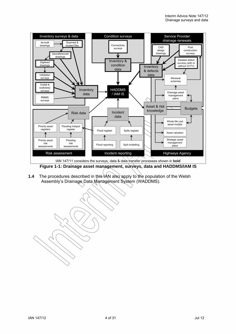
1.3 Figure 1-1 illustrates the surveys, data and data transfer methods included in this IAN
within the overall context of the management of the Highways Agency's drainage asset. The scanning, indexing, digitising and validation of all paper as-built drawings is an essential initial step in acquiring knowledge of the drainage asset, and in identifying the gaps in that knowledge. In areas where there is little or no asset knowledge an early priority is to identify the locations of all outfalls and soakaways by a combination of desk study and field survey. Connectivity surveys are considered to be a key method of infilling the missing areas of asset knowledge and then keeping that knowledge up to date with periodic resurveys of the drainage condition, although the method will not be suitable for all locations on the network. CCTV surveys will continue to be used for the detailed investigation of pipework defects in known problem areas, particularly prior to designing remedial or renewal works. A new detailed defect survey method for non-pipework assets is introduced. Detailed defect surveys with CCTV may also be the most cost effective method of surveying the drainage where the lack of a verge or hard shoulder makes it impractical to carry out the lower cost connectivity surveys. Post construction commissioning surveys may continue to use CCTV surveys or may, in appropriate circumstances, adopt the connectivity survey method. Drainage CAD design drawings are not suitable for directly populating the HADDMS/IAM IS databases, but can be processed for use. For each of the survey or data processing methods described, this IAN also defines the standard data outputs and formats to ensure that the data can be uploaded to HADDMS/IAM IS. The data can also be downloaded from HADDMS/IAM IS in similar formats for use off-line or in other systems.
Interim Advice Note 147/12 Drainage surveys and data
IAN 147/12 4 of 31 Jul 12
Inventory surveys & data Condition surveys Service Provider
drainage renewals
Highways AgencyIncident reportingRisk assessment
HADDMS / IAM IS
Inventory & condition
data
Inventory data
Incident data
BudgetsAsset & risk knowledge
Inventory & defects
data
Priority asset risk
assessments
Connectivity surveys
Flooding hotspot register Spills registerFlood register
Spill modelling
Whole life cost asset models
Asset valuation
Strategic asset management
plans
As-built drawings
Outfall & soakaway surveys
RMMS surveys
Flood reporting
Priority asset registers
Floodingrisk
assessments
Risk data
Post construction
surveys
Detailed defect surveys (with or without CCTV)
Renewal schemes
Drainage asset management
plans
CAD design
drawings
IAN 147/11 considers the surveys, data & data transfer processes shown in bold
Scanned & located files
Georeferenced drawings
Digitised drawings
Validation surveys
Inventory surveys & data Condition surveys Service Provider drainage renewals
Highways AgencyIncident reportingRisk assessment
HADDMS / IAM IS
Inventory & condition
data
Inventory data
Incident data
BudgetsAsset & risk knowledge
Inventory & defects
data
Priority asset risk
assessments
Connectivity surveys
Flooding hotspot register Spills registerFlood register
Spill modelling
Whole life cost asset models
Asset valuation
Strategic asset management
plans
As-built drawings
Outfall & soakaway surveys
RMMS surveys
Flood reporting
Priority asset registers
Floodingrisk
assessments
Risk data
Post construction
surveys
Detailed defect surveys (with or without CCTV)
Renewal schemes
Drainage asset management
plans
CAD design
drawings
IAN 147/11 considers the surveys, data & data transfer processes shown in bold
Scanned & located files
Georeferenced drawings
Digitised drawings
Validation surveys
Figure 1-1: Drainage asset management, surveys, data and HADDMS/IAM IS 1.4 The procedures described in this IAN also apply to the population of the Welsh
Assembly’s Drainage Data Management System (WADDMS).

Interim Advice Note 147/12 Drainage surveys and data
IAN 147/12 5 of 31 Jul 12
2. Drainage Surveys 2.1 Three types of drainage survey are defined:
Asset inventory surveys: Quick field surveys that either identify the location of priority assets or confirm the validity of existing inventory records. The surveys are selective and are unlikely to survey 100% of the assets in an area. “Asset inventory data” is defined in section 4 of this document.
Asset condition surveys: Field surveys that assess the condition of all drainage assets in an area at the asset level, without detailed recording of defects. Where the assets have not been previously recorded the survey also captures the basic asset inventory, but not the full detailed attributes of each asset. The survey also records how the assets connect together and flow directions. “Asset condition data” is defined in section 5 of this document.
Detailed defect surveys: Detailed field surveys to record all condition defects in the inspected drainage assets. For pipework, this will require internal CCTV survey. For non-pipework assets, it will involve detailed inspection, possibly with selective excavation of some buried assets. Where the asset inventory has not previously been recorded, or has not been recorded in detail, then the detailed inventory is also captured. The survey may focus on particular assets in an area of known performance problems, or may survey all the drainage assets in the area, in which case the survey also records how the assets connect together and flow directions. “Defect data” is defined in section 6 of this document.
2.2 ASSET INVENTORY SURVEYS Validation surveys 2.2.1 Validation surveys are intended only for use where drainage inventory held on
HADDMS/IAM IS has been derived from non-surveyed methods, such as scanning and digitising as-built or other drawings or other information. The validation survey is a rapid walk over inspection of a representative sample of each dataset, inspecting only the surface visible point assets and results in a high-level indication of the overall reliability of the original records. The method allows Service Providers to determine whether the records may be used as the basis for future condition surveys, or whether the area needs to be completely resurveyed. Where multiple overlapping datasets exist on HADDMS/IAM IS, the survey method also allows a decision to be made on which dataset should be retained and which should be deleted or merged. The survey method is not suited to recording previously unmapped assets.
Validation surveys shall be carried out in accordance with the “Guidance
Note on Drainage Validation Surveys”. The validation status shall be described using the coding given in “Drainage
Data Formats”, Appendix B. All data shall be produced in the shapefile format defined in "Drainage Data
Formats" Appendix A. All data shall be passed through the online checking facility on
HADDMS/IAM IS prior to submission.

Interim Advice Note 147/12 Drainage surveys and data
IAN 147/12 6 of 31 Jul 12
Outfall and soakaway surveys 2.2.2 Outfall and soakaway surveys are intended to find and record the locations of outfalls
and soakaways, as priority assets that may present a risk of pollution. The method could also be used for other priority assets. The method is a combination of desk study and walkover field survey and results in either isolated assets on HADDMS/IAM IS where no other data is available or data that should be merged with existing data in areas where there is partial coverage.
Outfall and soakaway surveys shall be carried out in accordance with the
“Guidance Note on Drainage Outfall and Soakaway Surveys”. The drainage inventory shall be described using the terminology and coding
given in HD43/04 as modified by Annex A of this IAN and as fully defined in "Drainage Data Formats" Appendix B.
All data shall be produced in the shapefile format defined in "Drainage Data Formats" Appendix A.
All data shall be passed through the online checking facility on HADDMS/IAM IS prior to submission.
2.3 ASSET CONDITION SURVEYS Connectivity surveys 2.3.1 The connectivity survey method can be used in several circumstances, in particular:
for the full surveying of the drainage inventory and asset level condition where there are currently no asset records
to infill and update inventory information where there are existing validated as-built records and to record current condition
to record only condition where there are good inventory records to resurvey current condition at intervals for spot surveys to investigate current performance problems
2.3.2 The method records the condition of each asset as a visually assessed structural and
service grade, it does not in general record detailed defect level observations, although this can be included if required on a selective basis. The method is quick and an order of magnitude cheaper than CCTV surveys, but is only cost effective where there is safe daytime access to the side of the road with little or no traffic management.
Connectivity surveys shall be carried out in accordance with the “Guidance
Note on Drainage Connectivity Surveys”. The drainage inventory shall be described using the terminology and coding
given in HD43/04 as modified by Annex A of this IAN and as fully defined in "Drainage Data Formats" Appendix B.
The drainage condition shall be described using the definitions given in the "Drainage Condition Quick Assessment Method" and the coding given in "Drainage Data Formats" Appendix B.
All data shall be produced in the shapefile format defined in "Drainage Data Formats" Appendix A.
All data shall be passed through the online checking facility on HADDMS/IAM IS prior to submission.
Post construction commissioning surveys 2.3.3 Where considered appropriate, post construction drainage commissioning surveys may
adopt the connectivity survey methodology as an alternative to the detailed defect CCTV survey methodology usually required in the past.

Interim Advice Note 147/12 Drainage surveys and data
IAN 147/12 7 of 31 Jul 12
2.4 DETAILED DEFECT SURVEYS Pipework only detailed defect CCTV surveys 2.4.1 CCTV surveys of pipework are carried out where there is a known performance
problem indicated by flooding or sections of poor condition pipework identified from earlier connectivity surveys. CCTV surveys may also be carried out where it is not cost effective to perform connectivity surveys due to a lack of safe access to the side of the road, and full traffic management is required. A CCTV survey records both structural and service defects in the pipework, as well as recording the detailed pipe inventory.
CCTV surveys shall be carried out in accordance with SD15/03 as modified
by Annex A of this IAN. The pipework inventory and defect observations shall be described using
the terminology and coding given in SD15/03 as modified by Annex A of this IAN, and as fully defined in "Drainage Data Formats" Appendix B.
All data shall be produced in either the WinCan 7.6 format or the DrainageXML format defined in "Drainage Data Formats" Appendix D, with the coding for inventory given in "Drainage Data Formats" Appendix B and the coding for observations given in Appendix C.
Non-pipework only detailed defect surveys 2.4.2 Detailed defect surveys of non-pipework assets are required where there is a known
performance problem or where connectivity surveys have identified areas of poor condition assets. The surveys consist of detailed inspection and recording of both structural and service defects in the assets. If the inventory has not previously been surveyed then a topographic survey is carried out to record the full inventory and physical attributes.
Non-pipework only detailed defect surveys shall be carried out in accordance
with the "Guidance Note on Drainage Defect Surveys". The drainage inventory shall be described using the terminology and coding
given in "Drainage Data Formats" Appendix B. The drainage defect observations shall be described using the terminology
and coding given in "Drainage Data Formats" Appendix C. All data shall be produced in the shapefile format defined in "Drainage Data
Formats" Appendix A. All data shall be passed through the online checking facility on
HADDMS/IAM IS prior to submission. Full asset detailed defect surveys 2.4.3 Full asset detailed defect surveys combine CCTV detailed defect surveys of pipework
with non-pipework detailed defect surveys to provide a full defect survey of the whole drainage asset. If the inventory has not previously been surveyed then a topographic survey is carried out to record the full inventory and physical attributes of the non-pipework assets and this is combined with the pipework inventory from the CCTV survey. To produce a single electronic deliverable from the two survey components an online process is provided on HADDMS/IAM IS to convert the CCTV data to shapefile format to allow it to be merged with the non-pipework survey data.
The CCTV component of the surveys shall be carried out in accordance with
SD15/03 as modified by Annex A of this IAN.

Interim Advice Note 147/12 Drainage surveys and data
IAN 147/12 8 of 31 Jul 12
The CCTV pipework inventory and defect observations shall be described using the terminology and coding given in SD15/03 as modified by Annex A of this IAN, and as fully defined in "Drainage Data Formats" Appendix B.
All data shall be produced in either the WinCan 7.6 format or the DrainageXML format defined in "Drainage Data Formats" Appendix D, with the coding for inventory given in "Drainage Data Formats" Appendix B and the coding for observations given in Appendix C. It shall be converted online using HADDMS/IAM IS to shapefile format, for merging with the non-pipework survey data.
The non-pipework component of the surveys shall be carried out in accordance with the "Guidance Note on Drainage Defect Surveys".
The non-pipework drainage inventory shall be described using the terminology and coding given in "Drainage Data Formats" Appendix B.
The non-pipework drainage defect observations shall be described using the terminology and coding given in "Drainage Data Formats" Appendix C.
The data from the two components of the survey shall be merged and produced in the shapefile format defined in "Drainage Data Formats" Appendix A. Merging of CCTV and non-CCTV data is described in "Drainage Data Formats" Appendix D.
All data shall be passed through the online checking facility on HADDMS/IAM IS prior to submission.
Post construction commissioning surveys 2.4.4 Where considered appropriate post construction drainage commissioning surveys may
adopt the above detailed defect survey methodology with CCTV.

Interim Advice Note 147/12 Drainage surveys and data
IAN 147/12 9 of 31 Jul 12
3. Drainage Drawings 3.1 Drainage as-built and design drawings provide a useful record of the drainage
inventory and can be processed for inclusion on HADDMS/IAM IS and then validated by field survey. There are three steps in the process of converting a paper drawing to drainage inventory data, and each step in the process can be stored on HADDMS/IAM IS.
Scanned and located drawings 3.2 The first step in converting a set of paper drainage drawings is to scan each drawing
and approximately locate it in geographic space so that an outline of the drawing may be displayed on the map in HADDMS/IAM IS to act as a visual index to the data. The scanned drawing file is held online and can be selected from the map index and downloaded.
Drainage drawings shall be scanned and indexed in accordance with
"Drainage Data Formats" Appendix E. All data shall be produced in the format defined in "Drainage Data Formats"
Appendix E. Georeferenced drawings 3.3 The second step in the process is to digitally cut out the mapping element of the
drainage drawing and precisely align it with the Ordnance Survey base mapping (the georeferencing process), so that it may be displayed as a mapping layer in HADDMS/IAM IS.
Drainage drawings shall be georeferenced and indexed in accordance with
"Drainage Data Formats" Appendix E. All data shall be produced in the format defined in "Drainage Data Formats"
Appendix E. Digitised drawings 3.4 The third step is to manually trace (digitise) the drainage assets from the
georeferenced drawing as points, lines and polygons. Each asset has attributes of asset type and any information on dimensions, materials, depths and flow direction shown on the drawings. This information is uploaded to HADDMS/IAM IS and becomes part of the drainage inventory.
The drainage inventory on georeferenced drawings shall be digitised and
attributed using the terminology and coding given in HD43/04 as modified by Section 4 and Annex A of this IAN, and as fully defined in "Drainage Data Formats" Appendices A and B.
All digitised data shall be checked by experienced drainage engineers who are independent of the team carrying out the digitising work, prior to submission.
All data shall be produced in the shapefile format defined in "Drainage Data Formats" Appendix A.
All data shall be passed through the online checking facility on HADDMS/IAM IS prior to submission.
Interim Advice Note 147/12 Drainage surveys and data
IAN 147/12 10 of 31 Jul 12
CAD drawings 3.5 The drainage inventory shown on drawings in CAD format cannot be directly added to
the HADDMS/IAM IS inventory as the data is a pictorial representation of the assets. However, CAD drawings can be processed for inclusion on HADDMS/IAM IS as either located drawings, georeferenced drawings, digitised drawings or attached documents.
Drainage drawings in CAD format shall be produced with reference to the
guidance contained in “Guidance for Drainage CAD Drawings”. Drainage drawings in CAD format shall be processed for inclusion on
HADDMS/IAM IS in the appropriate format in accordance with the “Drainage Data Formats".

Interim Advice Note 147/12 Drainage surveys and data
IAN 147/12 11 of 31 Jul 12
4. Asset Inventory Data 4.1 The inventory is a schedule of all the components that make up the highway drainage
asset. It includes details of each asset type, their component parts, materials and dimensions, and how the assets connect together to form a drainage system.
4.2 Of key importance to inventory data is accurate recording of location, both in terms of
absolute position to OS coordinates, and relative position to the HA network and other assets.
4.3 Drainage inventory data can be obtained in inventory surveys, condition surveys,
detailed defect surveys and from the processing of drainage drawings. 4.4 The asset types that comprise the inventory each fall within one of three classes based
on their geometry and representation within HADDMS/IAM IS:
Point items: such as chambers, gullies, outfalls, flow controls such as valves and weirs, and soakaways
Continuous (linear) items: such as pipes, culverts, ditches and channels Region (polygonal) items: such as balancing ponds and infiltration basins
4.5 Every inventory item has an “item type code”, which is determined by the primary asset
type. 4.6 Every inventory item then has a number of other attributes that describe the nature of
the asset, for example its dimensions, materials and component parts. 4.7 Correct identification of the primary asset item type is important as some assets may
serve more than one function. A particular example is an outlet containing a flow control device such as a penstock. The asset item type would be “outlet”, and the type of flow control is recorded as an attribute of the outlet.
4.8 The description of each asset type with synonyms, example photographs and
drawings, and their unique item type code is given in the Drainage Glossary (all referenced documents are listed in Section 7).
4.9 Pumping stations are a specialist asset and full description of their components is
beyond the scope of this IAN. They should be recorded as point items with the appropriate item type code, with further details added to HADDMS/IAM IS as attached documents.
4.10 Asset types with similar form and function are grouped together in Table 4-1.

Interim Advice Note 147/12 Drainage surveys and data
IAN 147/12 12 of 31 Jul 12
Table 4-1: High level grouping of drainage asset types Asset Group Geometry Example Asset Types
Chambers Point asset Manhole, Catchpit, Inspection Chamber, Rodding Eye, Soakaway Chamber, Soakaway Borehole, Bifurcation or Storm Overflow, Lamphole, Other Special Chamber
Gullies Point asset Gully Inlets and Outlets Point asset Outfall, Inlet, Outlet, Grip Inlet
Pipes Continuous asset Pipework, Gravity Drain, Rising Main, Culvert, Syphon, Land Drainage
Filter Drains Continuous asset Counterfort Drain, Combined Surface and Sub-Surface Filter Drain, Filter Drain, Soakaway Trench, Fin Drain, Narrow Filter Drain
Ditches and Channels Continuous asset
Ditch, Grip, Grassed Surface Water Channel or Swale, Surface Water Channel, Drainage Channel Block, Edge Channel, Combined Kerb and Drainage Channel, Combined Pipe and Channel Drain, Linear Drainage Channel
Informal Drainage Continuous asset Over the Edge
Ponds Region asset Pond, Detention Basin, Retention Pond, Sediment Pond, Infiltration Basin, Pollution Containment Pond or Tank, Wetlands, Reed Bed Treatment System
Point asset Flow Control Device (standalone), Interceptor, Oil Separator, Pumping Station
Continuous asset Linear Cellular Storage System Miscellaneous
Region asset Reservoir Pavement
Point asset Ghost Node, Phantom Node, Region Node, Connector Node
Drainage network modelling *
Continuous asset Phantom Connector, Region Connector * Note: “Drainage network modelling” item types do not represent a physical asset but are required to fully define a drainage network model on HADDMS/IAM IS. Their usage is described in Annex A.
Referencing
4.11 Every drainage asset within a set of data has a unique reference assigned by the supplier known as the “supplier’s asset reference”. In addition every asset will have a unique and permanent asset reference assigned by HADDMS/IAM IS, known as the “HADDMS asset reference”.
4.12 The supplier’s asset reference is assigned to each asset during a survey, digitising
as-built records or any other activity that results in the production of asset inventory data. This reference must be unique to each asset within a dataset but is not intended to be unique across the whole HA network, or even across a single Area. During subsequent updates to the dataset, this supplier’s asset reference must not be changed. With the proviso of section 4.14, the format of this reference is free but must not contain spaces and must contain at least one letter such that it is not numeric. Where Service Providers use a third party to produce data or carry out surveys, the format of the supplier's asset reference should be agreed in advance so that it can be retained from data capture through to upload to HADDMS/IAM IS.
4.13 The HADDMS asset reference is assigned by HADDMS/IAM IS when an asset is first
recorded on the system. The reference will be in the format described in HD43/04 clauses 4.9 and 8.5. This asset reference is permanent once assigned and must not be removed or changed during subsequent updates to the data. If removed, HADDMS/IAM IS will treat the asset as new and assign a new HADDMS asset reference. Previously assigned HADDMS asset references will never be re-assigned to new assets, even if that asset reference is no longer in use due to an asset being deleted.
4.14 Because HADDMS/IAM IS assigns an HD43/04 format asset reference, the supplier’s
asset reference must not also be in this format to avoid clashes between the two references. Non-compliance with this rule has led to assets having a similar, but not

Interim Advice Note 147/12 Drainage surveys and data
IAN 147/12 13 of 31 Jul 12
identical, supplier’s and HADDMS reference, or one asset having a supplier’s reference identical to the HADDMS reference of another asset.
4.15 As it is of primary importance that the HADDMS asset reference is unique and
permanent, an asset may have an HADDMS asset reference that is not in accordance with the format defined in HD43/04 in the following cases:
A point asset has its location corrected such that it is outside its original
10m grid square. The point asset retains its original HADDMS asset reference.
A continuous asset has its flow direction corrected such that its upstream and downstream nodes are swapped. The continuous asset retains its original HADDMS asset reference based on what would now be its downstream node.
Connectivity and flow direction 4.16 As well as classifying and recording details of each individual asset, a vital aspect of a
drainage network model is the connectivity and flow direction between assets. To achieve this, continuous items are connected via point items, such that all continuous items are required to have a point item at both ends. Multiple continuous items can connect to the same point item; for example, a single manhole point item could have two incoming pipes and one outgoing pipe.
4.17 To indicate flow direction, one of the two point items at the end of a continuous item is
nominated as its “upstream” point item; the other is its “downstream”. This is done by specifying the relevant point asset references as the upstream and downstream asset attributes of the continuous asset.
4.18 The above definition of connectivity and flow direction is mandatory for all continuous
items. However, it is accepted that the connectivity and/or flow direction is not always known so a means of recording the level of certainty is provided.
4.19 Point items may exist separately from other assets, but these should be joined with
continuous items where possible. 4.20 Where a continuous item connects part way along another continuous item, there is no
change to the rule that every continuous item must have a point item at either end. However, it is permitted to also have a point item part-way along a continuous item to allow for such connections, as described in Annex A2.2.
4.21 Region items are connected to other drainage assets via a “region node” point item at
their centre and by using imaginary continuous items, the flow of water through the pond can be defined. This is explained further in Annex A2.6.

Interim Advice Note 147/12 Drainage surveys and data
IAN 147/12 14 of 31 Jul 12
5. Asset Condition Data 5.1 The condition of the drainage asset is assessed in terms of both its structural and
service condition.
Structural Condition: relates to the fabric of the asset and the severity of the structural defects that affect its integrity. Structural defects are addressed by repairing or replacing the asset.
Service Condition: relates to the performance of the asset and the severity of the defects that affect its serviceability, but is independent of the structural condition. Service defects are addressed by maintenance of the asset such as cleansing or vegetation clearance.
5.2 Both the structural and service condition are assigned an asset level condition grade
number between 1 and 5. The general definition of the asset level condition grades is given in Table 5-1.
Table 5-1: Structural and service grade definitions
Grade Structural Condition Service Condition 1 No defects Clear 2 Superficial defects Superficial deposits with no loss of performance 3 Minor defects Performance slightly reduced 4 Major defects Performance severely reduced 5 Not fit for purpose or unsafe Blocked or unsafe condition
5.3 The condition grades are visually assessed in connectivity surveys using the "Drainage
Condition Quick Assessment Method" that gives detailed descriptions of the features of each grade for groups of assets of similar nature. Most grades are illustrated with example photographs. Individual defects are not recorded by the method.
5.4 Both the structural and service grade must be whole numbers, decimal grades are not
permitted. 5.5 Where inspection of an asset was attempted, but it was not possible to assess the
condition (for example due to access problems), a grade of 9 can be given. A grade of 0 is equivalent to no grade, indicating that assessment of the asset’s condition has not been attempted, for example because the asset record is being produced from a desk based study, or assessment of that asset’s condition was beyond the scope of a survey.
5.6 This IAN does not cover the condition assessment of specialist drainage assets such
as reservoir pavements, linear cellular storage systems or pumping stations. The condition of a pumping station may be assessed using the same criteria as for a chamber in terms of the structure that contains the pumps, but the mechanical and electrical components generally require a specialist inspection. Some of the components have a defined life that may not be obvious from a routine visual inspection. The specialist (M&E Engineer’s) report should be uploaded to HADDMS/IAM IS as an attached document.
Interim Advice Note 147/12 Drainage surveys and data
IAN 147/12 15 of 31 Jul 12
6. Detailed Defect Data 6.1 Detailed defect surveys record both the structural and service defects present in each
drainage asset, as defined in section 5.1 for asset condition surveys. The surveys also record other observations that do not relate to defects such as the water level at the time of the survey, or connecting side branches in pipework.
6.2 Individual service and structural defects within an asset are given both a defect code
that describes the type and nature of the defect and a defect score which describes the severity of the defect. Assets can contain any number of defects, each of which is coded and scored.
6.3 The codes for each defect type are listed in "Drainage Data Formats" Appendix C. For
pipework the codes are based on those stated in SD15/03 with some additions. For non-pipework assets, the codes are based on the BS EN 13508 coding method but, with the exception of chambers, have been generated specifically for this IAN.
6.4 For most users the survey software that they use in the field will automatically assign
the defect codes based on the user selecting from a drop down menu description of the nature and severity of each defect observed.
6.5 The scores for the severity of each defect type are listed in "Drainage Data Formats"
Appendix C and are based on the system defined in the Sewer Rehabilitation Manual 4th Edition for pipework. Scores increase with the severity of the defect within a range of 1 to 165 for structural defects, and between 0.5 and 20 for service defects.
6.6 Users should not assign defect scores as these will be automatically calculated by
HADDMS/IAM IS when the data is uploaded and any user assigned defect scores will be overwritten.
6.7 The defect level scores can be assessed for each asset to derive asset level structural
and service condition grades using the methods shown in Table 6-1, depending on the asset class and grade, and using the score bandings defined in Table 6-2. Peak structural or service score is taken as the highest structural or service defect level score within the asset. For continuous assets, the mean service score is defined as the sum of all service defect level scores, divided by the length of the asset in metres.
Table 6-1: Structural and service grade calculation method
Asset Class Structural Grade Service Grade Point Peak structural score Peak service score Continuous Peak structural score Worst grade defined by peak service score or
mean service score Region Peak structural score Peak service score

Interim Advice Note 147/12 Drainage surveys and data
IAN 147/12 16 of 31 Jul 12
Table 6-2: Structural and service grade definitions
Structural Condition Service Condition Peak Structural Score Range
Structural Grade
Peak Service Score Range*
Mean Service Score Range*
Service Grade
1–9 1 <1 <0.5 1 10–39 2 1.0–1.9 0.5–0.9 2 40–79 3 2.0–4.9 1.0–2.4 3 80–164 4 5.0–9.9 2.5–4.9 4 165 5 ≥10.0 ≥5.0 5 Unable to assess 9 Unable to assess Unable to assess 9 Not attempted 0 Not attempted Not attempted 0 * Peak and mean service score after rounding to 1 decimal
place 6.8 Users should not calculate asset level condition grades for any assets for which defects
have been recorded, as the asset level condition grades will be automatically calculated by HADDMS/IAM IS when the data is uploaded. Any user calculated condition grades will be overwritten if any defect data is present for an asset.

Interim Advice Note 147/12 Drainage surveys and data
IAN 147/12 17 of 31 Jul 12
7. Normative References HD43/04 Drainage Data Management System for Highways SD15/03 Implementation Standard for CCTV Survey of Highway Drainage Systems HADDMS guidance documents available at www.haddms.com:
Drainage Glossary Drainage Data Formats Guidance Note on Drainage Validation Surveys Guidance Note on Drainage Outfall and Soakaway Surveys Guidance Note on Drainage Connectivity Surveys Guidance Note on Drainage Defect Surveys Guidance for Drainage CAD Drawings Drainage Condition Quick Assessment Method
8. Informative references BS EN 13508-2:2003 Conditions of drain and sewer systems outside buildings – Part 2: Visual inspection coding system WRc (2001). Sewer Rehabilitation Manual Fourth Edition, WRc (Water Research Centre) Publications. Additional supporting material such as system user documentation, instructional videos and webinar recordings, index tools, example datasets and field survey tools are available as follows:
Those without access to HADDMS/IAM IS should use the “Downloads” link from the front page of www.haddms.com
Those with access to HADDMS/IAM IS should login to www.haddms.com and use the “Help > Downloads” item in the main menu
9. User support Enquiries related to the application of this IAN or any aspect of HADDMS usage or access should be directed to:
Email: [email protected] Telephone: 01527 68888 and request “HADDMS Support”
Interim Advice Note 147/12 Drainage surveys and data
IAN 147/12 18 of 31 Jul 12
Annex A. Changes to, and guidance on, HD43/04 and SD15/03 A1. Changes to HD43/04 and SD15/03 A1.1 Table A-1 summarises changes to the requirements of HD43/04 and SD15/03 that
variously address: incompatibilities between HD43/04 and SD15/03; clarifications of requirements; additional requirements due to new asset types; additional requirements needed to cater for the new survey and data types introduced by this IAN or additional requirements needed to meet the data requirements of HADDMS/IAM IS. The “Further detail” column contains references to sections in this IAN or other referenced documents that provide full information about the changes.

Interim Advice Note 147/12 Drainage surveys and data
IAN 147/12 19 of 31 July 12
Table A-1: Summary of changes to HD43/04 and SD15/03 Clause Nature of change Summary of change Further detail HD43/04 3.2 and Appendix A Clause superseded The symbols for displaying drainage assets are not relevant for electronic deliverables HD43/04 4.9, 8.5 Clause superseded HD43 format references are now assigned by HADDMS / IAM IS for new assets. All
assets to have a “supplier’s asset reference” not in HD43 format that is unique within a drainage scheme.
4.11–4.15; “Drainage Data Formats” Appendix A
HD43/04 Chapter 3; SD15/03 Part 5 F18
Clauses modified & extended
A number of new asset types are available for use in order that the drainage asset can be fully defined. In addition, some existing asset types have had their use modified or extended.
A2
HD43/04 Chapter 4–7; SD15/03 Part 2 9008
Clauses modified & extended
A significant number of new asset inventory attributes are available and a small number have been superseded or clarified. All attributes are available to all asset types of the same geometric group (point, continuous, region).
“Drainage Data Formats” Appendix A
HD43/04 Appendix B; SD15/03 Part 5
Clauses modified & extended
Inventory attribute codes from both HD43/04 and SD15/03 have been amalgamated and added to such that they are available to all survey methods.
“Drainage Data Formats” Appendix B
HD43/04 3.6 Clause superseded “Piped grip” now represented by a grip inlet and a pipe. A2.3.4 HD43/04 3.19, 5.16 Clause superseded “Ghost Manhole” is now “Ghost Node”. A2.5 HD43/04 3.19 Clause superseded Continuous assets with bends do not need to be split by a ghost node at each bend. A2.5.2 HD43/04 3.19 Clause extended Connector Nodes can be used to represent connections part-way along continuous
assets so that the continuous asset does not need to be split. A2.2, A2.5.3
HD43/04 3.14 Clause superseded An exfiltration ditch (linear soakaway) is recorded as a soakaway trench. “Drainage Data Formats” Appendix B
HD43/04 6.13; SD15/03 Part 5 F20/21
Clauses modified & extended
Previously the HD43/04 and SD15/03 procedures were contradictory. For circular cross-section pipes a new “pipe diameter” field is provided. For non-circular pipes both the pipe height and pipe width fields should be completed.
“Drainage Data Formats” Appendix A
SD15/03 Part 5 F32 Clause superseded Temperature may now not be a number but must be a pre-defined code. “Drainage Data Formats” Appendices A and B
SD15/03 Part 5 F35 Clause superseded Year of construction may now only be a year, not a range of years. Where a range would previously have been given, the middle year within the range is specified.
“Drainage Data Formats” Appendix A
SD15/03 Part 5 F28 Clause modified Existing categories of strategic drain have been amended. “Drainage Data Formats” Appendix B
SD15/03 Part 2 9005 Requirement added The coordinates of the chamber at each end of every survey run shall be surveyed and recorded within the electronic deliverable
“Drainage Data Formats” Appendix D
HD43/04 Chapter 1 Clause superseded HD43/04 Survey Inspection Sheets are superseded. HD43/04 Chapter 1 Requirement added Electronic deliverables as specified in this IAN are required for all submissions. “Drainage Data Formats”
Appendix A and B HD43/04 Chapter 1 Requirement added Paper, e-paper (PDF) and CAD-format deliverables are optional and must be specified
in the works order in addition to the electronic data formats specified in this IAN.
SD15/03 Part 2 9005 Requirement added Electronic deliverables as specified in this IAN are required for all submissions. “Drainage Data Formats” Appendix D

Interim Advice Note 147/12 Drainage surveys and data
IAN 147/12 20 of 31 July 12
Clause Nature of change Summary of change Further detail SD15/03 Part 2 9005 5–7 Clause superseded Video recordings on VHS are not accepted. Video to be provided as MPG files at a
resolution equivalent to DVD (720x576px, 25fps) or better. Video to be captured digitally, not digitised from tape.
SD15/03 Part 2 9005 13–19 Clause superseded Negative/print photographs are not accepted. Digital still photographs are required for all defects and may be provided as stills from the video, at the same resolution.
SD15/03 Part 2 9005 Requirement added Paper, e-paper (PDF) and CAD-format deliverables are optional and must be specified in the works order in addition to the electronic data formats specified in this IAN.
HD43/04 6.13 Clarification Ditch width is to be measured between the top of each bank, and the ditch depth is to be measured once any silt has been removed, or estimated if this is not practical. The average width and depth along the extent of the ditch should be provided. Where the dimensions as defined above significantly vary along the length, the ditch should be split into two or more separate items by ghost nodes.
A2.5.1
HD43/04 6.13 Clarification Channel width is measured between the top of each shoulder. HD43/04 4.14–4.16 Clarification Downstream watercourse information is a function of the environment outside the HA
drainage network. Reference should be made where possible to any relevant data held in EnvIS.
HD43/04 Requirement added The full geometry of counterfort and “herringbone” drains should be captured during field surveys.
HD43/04 and SD15/03 Requirement added All surveys shall report horizontal and vertical measurements to the following minimum accuracy dependent on the type of survey being carried out.
Survey type Horizontal accuracy
Vertical accuracy
Inventory surveys ± 5 metres Not surveyed Condition surveys ± 1 metre Not surveyed Detailed defect surveys ± 100 mm ± 50 mm
HD43/04 and SD15/03 Requirement added All drainage asset data shall be grouped within a “drainage scheme”, which is a self-contained set of connected drainage assets. Where possible drainage schemes should contain all drainage assets within their extents, and overlap and duplication of assets between schemes should be avoided. All physically connected drainage assets within a catchment should be included in the same scheme.
“Drainage Data Formats” Appendix A
HD43/04 Requirement added Scanned or other electronic drainage drawings shall be grouped within a “drawing set”. This would normally comprise all drainage related drawings from a single construction or maintenance scheme. In some cases, a drawing set may correspond with a drainage scheme.
“Drainage Data Formats” Appendix E

Interim Advice Note 147/12 Drainage surveys and data
IAN 147/12 21 of 31 July 12
A2. Additional and modified inventory item types The following sections give details of additional inventory item types that have
been added in order to allow a full definition of a drainage network model. A2.1 Phantom Nodes and Phantom Connectors
Item type Phantom Node Phantom Connector Item type group Network Modelling Network Modelling Inventory type Point Continuous Item type code PN PL
A2.1.1 Phantom nodes provide an upstream and/or downstream end point of a drainage
system, when the nature of the drainage system beyond the phantom node is unknown, because either there are no as-built drawings or it has not been surveyed.
A2.1.2 Phantom nodes will occur at the end of a drainage scheme, located at the farthest
known location along the continuous item to which they are connected. They satisfy the requirement that every continuous item must have a point item at each end.
A2.1.3 Figure A-1 shows that an upstream pipe exists but no upstream point item is
shown, as it is beyond the extent of the available as-built drawings. In this case a phantom node is used (Figure A-2), as the upstream node of the pipe.
Edge of scheme, no further drawings available
MH MHEdge of scheme, no
further drawings available
MH MH
Figure A-1: Incomplete inventory at extent of available records
Edge of scheme, no further drawings available
MH MHPNEdge of scheme, no further drawings available
MH MHPN
Figure A-2: Incomplete inventory with phantom node
A2.1.4 Where a CCTV survey is prematurely terminated by a blockage in the pipe run,
and the end manhole cannot be found, then the limit of the survey can be defined as a phantom node. However, where the end manhole can be found, or reasonably identified, then there is no need for a phantom node.
A2.1.5 A phantom connector is a connection between two known point items in which
the route of the continuous connection between them is unknown, but there is some degree of certainty that the two are connected. A phantom connector should be used if an area of an as-built drawing is obscured (Figure A-3 and Figure A-4), or where a below ground pipework survey has not been carried out but the pipework route can be established with some degree of certainty, for example by dye tracing.

Interim Advice Note 147/12 Drainage surveys and data
IAN 147/12 22 of 31 July 12
A2.1.6 Phantom connectors are solely used to indicate connectivity for flow modelling. The connectivity certainty attribute is set to ‘Y’ or ‘N’ as appropriate, depending on whether connectivity is established (e.g. by dye tracing) or inferred between the two point items.
A2.1.7 A single phantom connector may represent several items in reality. This is distinct
from other types of continuous item with uncertain connectivity, where the nature of the item is otherwise known. The extensive use of phantom connectors is discouraged. If the surface manholes, gullies, headwalls, etc. can be identified, and the nature of the connection between them can be reasonably inferred, then they should be recorded with the appropriate pipework item, and not by a phantom connector.
MH MH
Obscured part of drainage scheme drawing
MHMH MH MH
Obscured part of drainage scheme drawing
MHMH
Figure A-3: Incomplete inventory due to missing information
MH MH
PhantomConnector
MHMH MH MH
PhantomConnector
MHMH
Figure A-4: Incomplete inventory with phantom connector
A2.2 Connector Nodes and Connectivity Attributes
Item type Connector Node Item type group Network Modelling Inventory type Point Item type code CN
A2.2.1 In HD43/04, a carrier pipe between two manholes that has side connections from
a number of gullies must be split into multiple separate pipes. At each side connection, a ghost node (referred to as a “ghost manhole” in HD43/04) must be defined, as illustrated in Figure A-5 below.

Interim Advice Note 147/12 Drainage surveys and data
IAN 147/12 23 of 31 July 12
Individual sections of carrier pipe item between nodes
Ghost node
GU1 GU2 GU3
GN1 GN2 GN3MH1 MH2
PW1 PW2 PW3 PW4
Individual sections of carrier pipe item between nodes
Ghost node
GU1 GU2 GU3
GN1 GN2 GN3MH1 MH2
PW1 PW2 PW3 PW4
Figure A-5: Use of ghost nodes to connect gullies with carrier pipes (as previously required in HD43/04)
A2.2.2 In SD15/03, the carrier pipe between MH1 and MH2 in Figure A-5 would have a
single pipe reference, and would not be split into multiple separate pipes. A2.2.3 This IAN and HADDMS permit either the HD43/04 or the SD15/03 methods of
representing the carrier pipe. However, the SD15/03 method is modified to allow the flow connectivity between the gully connector side pipes and the carrier pipes to be defined. In addition, a third method is added for when the side connection is inferred but the location is unknown.
A2.2.4 The modified SD15/03 method requires a new “connector node” point item type.
All connector nodes have a “connectivity attribute”, which gives the pipe reference of the continuous item to which they are connected. A connector node therefore differs from all other point item types, in that it does not split the continuous item on which it lies. In the example in Figure A-6 below, gully GU2 is connected to connector node CN1 by a length of pipework PW10. The upstream reference of PW10 is GU2, and the downstream reference is CN1. The carrier pipe between manholes MH1 and MH2 has a single pipe reference of PW1. The connectivity attribute of CN1 (and CN2) would be PW1.
Single carrier pipe item between manholes ("PW1")
Gully with connectivity attribute providing carrier
pipe reference
GU1 GU2 GU3
MH1
CN1 CN2
MH2
Gully connector pipesConnector node at
junction, with connectivity attribute providing carrier pipe
reference
PW10PW11
Single carrier pipe item between manholes ("PW1")
Gully with connectivity attribute providing carrier
pipe reference
GU1 GU2 GU3
MH1
CN1 CN2
MH2
Gully connector pipesConnector node at
junction, with connectivity attribute providing carrier pipe
reference
PW10PW11
Figure A-6: Use of connector nodes and connectivity attributes to connect gullies and carrier pipes

Interim Advice Note 147/12 Drainage surveys and data
IAN 147/12 24 of 31 July 12
A2.2.5 If a CCTV survey has not been carried out, it can be established or reasonably inferred that gully GU1 is connected to pipe PW1 in Figure A-6, but the location of the connection is unknown. In this case, no gully connector pipe is shown, but the inferred connectivity is defined by recording the connectivity attribute of gully GU1 as “PW1”.
A2.2.6 Connector nodes and other point items with connectivity attributes can also be
used in other situations. For example, where there is no formal drainage system, an “over-the-edge” continuous item is represented along the edge of the carriageway with a ghost node at each end, as shown in Figure A-7. The ghost nodes must be assigned as upstream and downstream, but the flow direction certainty of the over-the-edge item should be set to ‘N’ unless the carriageway gradient is known. If there is a subsequent drainage system such as a ditch, the connectivity attribute of the downstream ghost node is defined as the asset reference of the ditch for flow modelling purposes. Where there is no subsequent drainage system, no connectivity is defined.
Carriageway (at top of embankment)
Ghost node(downstream) with connectivity attribute = “DI1”
Ghost node(upstream)
Over the edge item
Ditch (reference = “DI1”)
Embankment slope
Carriageway (at top of embankment)
Ghost node(downstream) with connectivity attribute = “DI1”
Ghost node(upstream)
Over the edge item
Ditch (reference = “DI1”)
Embankment slope
Figure A-7: Example of “over-the-edge” drainage
A2.2.7 Where a grip is present at the top of an embankment (represented by a “grip
inlet” point item), and water flows freely down the slope, to a ditch at the toe, as shown in Figure A-8. As no continuous item can be defined between the grip inlet and the ditch, the flow connectivity is defined by recording the asset reference of the ditch in the connectivity attribute of the grip inlet.

Interim Advice Note 147/12 Drainage surveys and data
IAN 147/12 25 of 31 July 12
Carriageway (at top of embankment)
Grip inletwith connectivity attribute = “DI1”
Ditch (reference = “DI1”)
Embankment slopeGrip inlet
with connectivity attribute = “DI1”
Grip inletwith connectivity attribute = “DI1”Carriageway (at top of embankment)
Grip inletwith connectivity attribute = “DI1”
Ditch (reference = “DI1”)
Embankment slopeGrip inlet
with connectivity attribute = “DI1”
Grip inletwith connectivity attribute = “DI1”
Figure A-8: Example of grip inlets without formal drainage
A2.2.8 Where there is a surface channel between the grip inlet and the ditch then this
would be recorded in the normal way as a grip continuous item. At the downstream end of the grip, where it connects with the ditch, a connector node is recorded, which has a connectivity attribute defined as the asset reference of the ditch, as shown in Figure A-9. The grip inlets do not have any connectivity attribute defined. If the grip is a pipe, it is represented by an asset with item type “PW”. If the grip does not extend to the ditch, but water flows informally down the slope, it is represented in a similar manner, as shown in the right-most example in Figure A-9.
Carriageway (at top of embankment)
Grip inlet
Ditch (reference = “DI1”)
Grip inlet Grip inlet
Connector nodewith connectivity attribute = “DI1”
Grip Grip
Grip(not extending to the ditch)
Connector nodewith connectivity attribute = “DI1”
Connector nodewith connectivity attribute = “DI1”
Embankment slope
Figure A-9: Example of grip inlets with formal drainage

Interim Advice Note 147/12 Drainage surveys and data
IAN 147/12 26 of 31 July 12
A2.3 Inlets, Outlets, Outfalls and Grip Inlets
Item type Inlet Outlet Outfall Grip Inlet Item type group Inlets and Outlets Inventory type Point Point Point Point Item type code IT OL OU GI
A2.3.1 An inlet is a point item at which water flows from an open surface continuous
item (such as a ditch) or region item to a sub-surface continuous item (such as pipework or a culvert). As shown in Figure A-10, a ditch flowing into a culvert to pass underneath a road would have, at the junction between the two continuous items, an inlet. The attributes associated with the inlet item will define its individual properties, such as a headwall.
A2.3.2 An outlet is a point item that enables water to flow from a sub-surface
continuous item (such as pipework or a culvert) to a surface continuous item (such as a ditch) or region item. Continuing the example from above, a culvert flowing into a ditch as it emerges from beneath the road would have, at the junction between the two continuous items, an outlet.
A2.3.3 An outfall must be defined where the highway drainage system discharges into a
third party system such as a watercourse, tidal waters or sewer. This is at the ownership boundary of the drainage network, which is usually, but not always, at the Highways Agency property boundary. Where an outfall occurs at the location of an outlet or other point item, the item type of outfall always takes precedence.
A2.3.4 At the upstream end of a piped grip or non-piped grip, the point item will be a grip
inlet. As described in section A2.2.5, a grip inlet may also exist without a specific downstream asset. This item type supersedes the HD43 “Piped Grip (PG)” point item type. If the grip inlet is an inlet to a piped grip, then the continuous asset will be of type “PW”. If the grip inlet is an inlet to any other sort of grip, the continuous asset will be of type “GP”.
A2.3.5 An example usage of inlets, outlets and outfalls is shown in Figure A-10.
Examples of grip inlets are shown in the figures in section A2.2.5.
Carriageway
Inlet
Outlet
Ditch (surface continuous item)
Culvert (sub-surface continuous item)
Ditch (surface continuous item)
Outfall at point where drainage leaves HA ownership
Carriageway
Inlet
Outlet
Ditch (surface continuous item)
Culvert (sub-surface continuous item)
Ditch (surface continuous item)
Outfall at point where drainage leaves HA ownership
Figure A-10: Use of inlets, outlets and outfalls

Interim Advice Note 147/12 Drainage surveys and data
IAN 147/12 27 of 31 July 12
A2.3.6 For example, an outfall would be located where a surface continuous item (e.g. a ditch) or a subsurface continuous item (e.g. a culvert) discharges into a stream or river. Also, an outfall is located where a subsurface continuous item (e.g. pipework) discharges into a sewer. A soakaway is not an outfall.
A2.3.7 Where an open continuous or region item, such as a ditch or pond, flows into
another open item, inlets or outlets are not appropriate. If there is a means of flow control such as a weir, a flow control device (as described in Annex A2.4) is used, otherwise a ghost node (as described in Annex A2.5). Suitable layouts for region items are shown in Annex A2.6.
A2.3.8 Where a third-party drainage system flows into the highways drainage, a point
item is defined as normal. The Owner attribute of the point item is recorded as “Private” or “Public” as appropriate. The name of the owner may be entered in the Remarks field.
A2.3.9 Attributes of these assets are completed as normal; however, recording the
presence or lack of a headwall or other formal structure is of increased importance.
A2.4 Flow Control Devices
Item type Flow Control Device Item type group Miscellaneous Inventory type Point Item type code FC
A2.4.1 A flow control device is a standalone item that is used to control water flow (such
as a penstock or weir). Other point inventory items can include one or more flow control attributes, so that a manhole can include a flap valve, or an inlet can include an orifice plate, for example. However, where a flow control device operates independently of any other point inventory item, such as a weir in a ditch, it should be recorded as a separate “Flow Control Device” item, the attributes identifying what type of flow control device it is.
A2.4.2 Where a flow control device is situated part way along a continuous asset, such
as a weir in a ditch, the continuous asset is split into two assets. A2.4.3 In accordance with HD33/06 8.3, where signage exists indicating the location of a
pollution control device, this shall be indicated in the record for the point item by the “SIGN” attribute, and described in the “REMARKS” attribute. If appropriate, a photograph of the sign may be attached.

Interim Advice Note 147/12 Drainage surveys and data
IAN 147/12 28 of 31 July 12
A2.5 Ghost Nodes
Item type Ghost Node Item type group Network Modelling Inventory type Point Item type code GN
A2.5.1 The ghost node (previously “ghost manhole” in HD43/04) has several uses but is
primarily to aid in the completion of a network model by representing a node that has no physical manifestation. The uses include:
The ends of ditches or other continuous items where there is no
other point inventory item. A point where the nature of a ditch or other continuous item
significantly changes, such as a watershed where the flow direction changes, but there is otherwise no physical item. In this case, the continuous item would be split into two items, connected by the ghost node.
At the connection between two surface assets such as a ditch and a pond, where there is no physical asset such as a flow control device.
A2.5.2 The HD43/04 requirement to use a ghost node to mark a bend in a continuous
item is removed. Curved continuous items should be represented by GIS polylines.
A2.5.3 The HD43/04 requirement to use a ghost node to show the position of a junction
where there is no manhole is replaced by the new Connector Node item type (Annex A2.2).
A2.5.4 The HD43/04 requirement to use a ghost node for the centroid of a region item is
replaced by the new item type Region Node (Annex A2.6). A2.6 Region Items and Region Nodes
Item type Region Node Item type group Network Modelling Inventory type Point Item type code RN
A2.6.1 Usage of a ghost node at the centroid of a region item is now replaced by a
region node. A2.6.2 The region node has the same supplier’s and HADDMS references as the region
item itself. There must only be one region node per region item. A2.6.3 Region nodes are permitted without a corresponding region item, in the case
where the region item boundary has not yet been surveyed, for example. It is anticipated that such a region item would be added in future, however, as the region item contains key attributes not present for the region node.
A2.6.4 Region connectors are used to model the flow of drainage through the pond.
Region nodes should only be connected by region connectors. Region connectors should always have a region node at one end.

Interim Advice Note 147/12 Drainage surveys and data
IAN 147/12 29 of 31 July 12
A2.6.5 An example arrangement of region nodes, region items and region connectors is shown in Figure A-11. The region item has two incoming continuous assets: a pipe and a ditch; and one outgoing continuous asset: a channel. Where the pipe ends at the pond, there is an outlet as the drainage system is changing from sub-surface to open. There is no physical asset where the ditch enters the pond, but there must be a point item at the end of the ditch, so this will be a ghost node. Where the pond flows into the channel there is a weir, which is represented by a flow control device point item. Region connectors join the region node to each point where a continuous asset enters or leaves the region item.
Regionnode Channel
Region itemOutlet
Ditch
Region connectors
Flow control device
Pipe
Ghostnode
Regionnode Channel
Region itemOutlet
Ditch
Region connectors
Flow control device
Pipe
Ghostnode
Figure A-11: Region nodes, region items and region connectors
A2.7 Combined pipe and filter drains
Item type Combined surface and sub-surface filter drain Item type group Filter Drains Inventory type Continuous Item type code CF
A2.7.1 This item type is to be used specifically for a filter drain with a single integrated
porous or perforated pipe. Such an asset is modelled as a single asset of type “CF”, not as separate pipe and filter drain assets. The following should be noted when recording data related to such assets:
The “WIDTH” and “HEIGHT” attributes relate to the filter drain media. The diameter of the pipe is recorded in the “PIPE_DIA” attribute. The “POROUS” or “PERFORATED” attributes should be populated
as appropriate. All pipe and filter drain observations are applicable to the “CF” asset
type, except those pipe observations not relevant to porous or perforated pipes.
The asset has one structural condition grade and one service condition grade, based on the most severe defect in either the pipe or filter drain part of the asset.

Interim Advice Note 147/12 Drainage surveys and data
IAN 147/12 30 of 31 July 12
A2.7.2 In the case where the filter drain contains a single pipe that is not porous or perforated, this pipe should be modelled as a separate asset from the filter drain. Therefore the filter drain is recorded as item type “FD” (filter medium only), and the pipe as appropriate, e.g. “PW”. The following should be noted:
Normally, both assets will share the same location, and have the
same upstream and downstream point items. It is not necessary to model the two assets in artificially different x-y positions.
The pipe and filter drain assets must have different asset references; however, it is suggested that similar references are assigned to indicate the assets’ relationship.
All attribute data relates specifically to either the pipe or filter drain. The “PIPE_DIA” attribute must not be completed for the filter drain (“FD”) asset, but should be completed for the pipe if it is of circular cross-section.
Condition is recorded separately for each asset.
A2.7.3 In the case where the filter drain includes a porous or perforated pipe and an additional pipe that is not porous or perforated, the latter is recorded as a separate pipe (e.g. item type “PW”), in addition to the “CF” item as described in section A2.7.1.
A2.8 Other additional asset types A2.8.1 In addition to the above, the following asset item types have been added and are
described in the Drainage Glossary.
Table A-2: List of other additional item types Item type Item type
group Geometry type Item type
code Soakaway Borehole (or “Well”) Chambers Point item SB Linear Cellular Storage System (not used as soakaway)
Miscellaneous Continuous item LS
Soakaway Trench Filter Drains Continuous item ST Pond (undifferentiated) Ponds Region item PU Reed Bed Treatment System Ponds Region item RB Reservoir Pavement Miscellaneous Region item RV

Interim Advice Note 147/12 Drainage surveys and data
IAN 147/12 31 of 31 July 12
Annex B: IAN 147/11 - Amendments required to this IAN when used in projects carried out under English DBFO contracts When used on the M25 DBFO Scheme, this IAN is to be amended as follows:
Para No. Description 4.2 Delete “HA network” and insert “Project Road” 4.12 Delete “, or even across a single Area” 4.14 Delete "supplier's and HADDMS reference" and insert "suppliers'
and HADDMS references" 5.6 Delete "(M&E Engineer's)" and insert "(M&E engineers)"
When used on all other English DBFO Schemes, this IAN is to be amended as follows:
Para No. Description 2.2.1 Delete “Service Providers” and insert “DBFO Cos” 4.2 Delete “HA network” and insert “Project Road” 4.12 Delete “, or even across a single Area”
Delete “Service Providers” and insert “DBFO Cos” 4.14 Delete "supplier's and HADDMS reference" and insert "suppliers'
and HADDMS references" 5.6 Delete "(M&E Engineer's)" and insert "(M&E engineers)"