international iec standard 61131-3...part 3: programming languages automates programmables –...
TRANSCRIPT

INTERNATIONAL STANDARD
IEC61131-3
Second edition2003-01
Programmable controllers –
Part 3: Programming languages
Automates programmables –
Partie 3: Langages de programmation
Reference number IEC 61131-3:2003(E)
Copyright International Electrotechnical Commission Provided by IHS under license with IEC Licensee=Technip Abu Dabhi/5931917101
Not for Resale, 02/12/2006 07:01:30 MSTNo reproduction or networking permitted without license from IHS
--``,`,`,,,``````,,``,,``,,,,`,-`-`,,`,,`,`,,`---

Publication numbering
As from 1 January 1997 all IEC publications are issued with a designation in the 60000 series. For example, IEC 34-1 is now referred to as IEC 60034-1.
Consolidated editions
The IEC is now publishing consolidated versions of its publications. For example, edition numbers 1.0, 1.1 and 1.2 refer, respectively, to the base publication, the base publication incorporating amendment 1 and the base publication incorporating amendments 1 and 2.
Further information on IEC publications
The technical content of IEC publications is kept under constant review by the IEC, thus ensuring that the content reflects current technology. Information relating to this publication, including its validity, is available in the IEC Catalogue of publications (see below) in addition to new editions, amendments and corrigenda. Information on the subjects under consideration and work in progress undertaken by the technical committee which has prepared this publication, as well as the list of publications issued, is also available from the following:
• IEC Web Site (www.iec.ch)
• Catalogue of IEC publications
The on-line catalogue on the IEC web site (http://www.iec.ch/searchpub/cur_fut.htm) enables you to search by a variety of criteria including text searches, technical committees and date of publication. On-line information is also available on recently issued publications, withdrawn and replaced publications, as well as corrigenda.
• IEC Just Published
This summary of recently issued publications (http://www.iec.ch/online_news/ justpub/jp_entry.htm) is also available by email. Please contact the Customer Service Centre (see below) for further information.
• Customer Service Centre
If you have any questions regarding this publication or need further assistance, please contact the Customer Service Centre:
Email: [email protected] Tel: +41 22 919 02 11 Fax: +41 22 919 03 00
Copyright International Electrotechnical Commission Provided by IHS under license with IEC Licensee=Technip Abu Dabhi/5931917101
Not for Resale, 02/12/2006 07:01:30 MSTNo reproduction or networking permitted without license from IHS
--``,`,`,,,``````,,``,,``,,,,`,-`-`,,`,,`,`,,`---

INTERNATIONAL STANDARD
IEC61131-3
Second edition2003-01
Programmable controllers –
Part 3: Programming languages
Automates programmables –
Partie 3: Langages de programmation
IEC 2003 Copyright - all rights reserved
No part of this publication may be reproduced or utilized in any form or by any means, electronic or mechanical, including photocopying and microfilm, without permission in writing from the publisher.
International Electrotechnical Commission, 3, rue de Varembé, PO Box 131, CH-1211 Geneva 20, SwitzerlandTelephone: +41 22 919 02 11 Telefax: +41 22 919 03 00 E-mail: [email protected] Web: www.iec.ch
For price, see current catalogue
PRICE CODE
Commission Electrotechnique InternationaleInternational Electrotechnical CommissionМеждународная Электротехническая Комиссия
XE
Copyright International Electrotechnical Commission Provided by IHS under license with IEC Licensee=Technip Abu Dabhi/5931917101
Not for Resale, 02/12/2006 07:01:30 MSTNo reproduction or networking permitted without license from IHS
--``,`,`,,,``````,,``,,``,,,,`,-`-`,,`,,`,`,,`---
– 2 – 61131-3 IEC:2003(E)
CONTENTS
FOREWORD ....................................................................................................................................8
1 General ........................................................................................................................................9 1.1 Scope.........................................................................................................................................9 1.2 Normative references ................................................................................................................9 1.3 Definitions..................................................................................................................................9 1.4 Overview and general requirements .......................................................................................14 1.4.1 Software model.....................................................................................................................14 1.4.2 Communication model..........................................................................................................16 1.4.3 Programming model .............................................................................................................18 1.5 Compliance..............................................................................................................................19 1.5.1 System compliance ..............................................................................................................20 1.5.2 Program compliance.............................................................................................................22
2 Common elements .....................................................................................................................23 2.1 Use of printed characters ........................................................................................................23 2.1.1 Character set ........................................................................................................................23 2.1.2 Identifiers ..............................................................................................................................23 2.1.3 Keywords..............................................................................................................................24 2.1.4 Use of white space ................................................................................................................24 2.1.5 Comments ............................................................................................................................24 2.1.6 Pragmas ...............................................................................................................................25 2.2 External representation of data ...............................................................................................25 2.2.1 Numeric literals.....................................................................................................................25 2.2.2 Character string literals ........................................................................................................26 2.2.3 Time literals ..........................................................................................................................28 2.2.3.1 Duration .............................................................................................................................28 2.2.3.2 Time of day and date.........................................................................................................29 2.3 Data types ...............................................................................................................................29 2.3.1 Elementary data types..........................................................................................................30 2.3.2 Generic data types ...............................................................................................................31 2.3.3 Derived data types................................................................................................................32 2.3.3.1 Declaration ........................................................................................................................32 2.3.3.2 Initialization........................................................................................................................33 2.3.3.3 Usage .................................................................................................................................35 2.4 Variables..................................................................................................................................36 2.4.1 Representation .....................................................................................................................36 2.4.1.1 Single-element variables ...................................................................................................36 2.4.1.2 Multi-element variables .....................................................................................................38 2.4.2 Initialization...........................................................................................................................38 2.4.3 Declaration ...........................................................................................................................39 2.4.3.1 Type assignment ...............................................................................................................41 2.4.3.2 Initial value assignment .....................................................................................................42 2.5 Program organization units .....................................................................................................45 2.5.1 Functions ..............................................................................................................................45 2.5.1.1 Representation ..................................................................................................................46 2.5.1.2 Execution control ...............................................................................................................49 2.5.1.3 Declaration ........................................................................................................................50 2.5.1.4 Typing, overloading, and type conversion.........................................................................52 2.5.1.5 Standard functions.............................................................................................................55 2.5.1.5.1 Type conversion functions..............................................................................................55 2.5.1.5.2 Numerical functions........................................................................................................56 2.5.1.5.3 Bit string functions ..........................................................................................................59 2.5.1.5.4 Selection and comparison functions...............................................................................59 2.5.1.5.5 Character string functions ..............................................................................................62 2.5.1.5.6 Functions of time data types ..........................................................................................64 2.5.1.5.7 Functions of enumerated data types..............................................................................66
Copyright International Electrotechnical Commission Provided by IHS under license with IEC Licensee=Technip Abu Dabhi/5931917101
Not for Resale, 02/12/2006 07:01:30 MSTNo reproduction or networking permitted without license from IHS
--``,`,`,,,``````,,``,,``,,,,`,-`-`,,`,,`,`,,`---

61131-3 IEC:2003(E) – 3 –
2.5.2 Function blocks.....................................................................................................................662.5.2.1 Representation ..................................................................................................................672.5.2.1a) Use of EN and ENO in function blocks ............................................................................682.5.2.2 Declaration ........................................................................................................................692.5.2.3 Standard function blocks ...................................................................................................772.5.2.3.1 Bistable elements ...........................................................................................................772.5.2.3.2 Edge detection................................................................................................................782.5.2.3.3 Counters .........................................................................................................................782.5.2.3.4 Timers.............................................................................................................................812.5.2.3.5 Communication function blocks......................................................................................832.5.3 Programs ..............................................................................................................................832.6 Sequential Function Chart (SFC) elements.............................................................................842.6.1 General .................................................................................................................................842.6.2 Steps.....................................................................................................................................842.6.3 Transitions ............................................................................................................................862.6.4 Actions..................................................................................................................................892.6.4.1 Declaration ........................................................................................................................892.6.4.2 Association with steps .......................................................................................................912.6.4.3 Action blocks .....................................................................................................................922.6.4.4 Action qualifiers .................................................................................................................932.6.4.5 Action control.....................................................................................................................942.6.5 Rules of evolution .................................................................................................................992.6.6 Compatibility of SFC elements ...........................................................................................1072.6.7 SFC Compliance requirements ..........................................................................................1082.7 Configuration elements..........................................................................................................1082.7.1 Configurations, resources, and access paths ....................................................................1102.7.2 Tasks ..................................................................................................................................114
3 Textual languages ....................................................................................................................1233.1 Common elements ................................................................................................................1233.2 Instruction list (IL) ..................................................................................................................1233.2.1 Instructions .........................................................................................................................1233.2.2 Operators, modifiers and operands....................................................................................1243.2.3 Functions and function blocks ............................................................................................1263.3 Structured Text (ST) ..............................................................................................................1293.3.1 Expressions ........................................................................................................................1293.3.2 Statements .........................................................................................................................1313.3.2.1 Assignment statements ...................................................................................................1333.3.2.2 Function and function block control statements ..............................................................1333.3.2.3 Selection statements .......................................................................................................1333.3.2.4 Iteration statements .........................................................................................................134
4 Graphic languages ...................................................................................................................1354.1 Common elements ................................................................................................................1354.1.1 Representation of lines and blocks .....................................................................................1354.1.2 Direction of flow in networks...............................................................................................1354.1.3 Evaluation of networks .......................................................................................................1364.1.4 Execution control elements ................................................................................................1384.2 Ladder diagram (LD) .............................................................................................................1394.2.1 Power rails ..........................................................................................................................1394.2.2 Link elements and states....................................................................................................1394.2.3 Contacts .............................................................................................................................1404.2.4 Coils....................................................................................................................................1404.2.5 Functions and function blocks ............................................................................................1404.2.6 Order of network evaluation ...............................................................................................1414.3 Function Block Diagram (FBD)..............................................................................................1434.3.1 General ...............................................................................................................................1434.3.2 Combination of elements....................................................................................................1434.3.3 Order of network evaluation ...............................................................................................143
Copyright International Electrotechnical Commission Provided by IHS under license with IEC Licensee=Technip Abu Dabhi/5931917101
Not for Resale, 02/12/2006 07:01:30 MSTNo reproduction or networking permitted without license from IHS
--``,`,`,,,``````,,``,,``,,,,`,-`-`,,`,,`,`,,`---

– 4 – 61131-3 IEC:2003(E)
ANNEX A (normative) Specification method for textual languages ............................................144A.1 Syntax ...................................................................................................................................144A.1.1 Terminal symbols .............................................................................................................144A.1.2 Non-terminal symbols ......................................................................................................144A.1.3 Production rules ................................................................................................................145A.2 Semantics .............................................................................................................................145
ANNEX B (normative) Formal specifications of language elements...........................................146B.0 Programming model..............................................................................................................146B.1 Common elements ................................................................................................................146B.1.1 Letters, digits and identifiers ...............................................................................................146B.1.2 Constants ...........................................................................................................................147B.1.2.1 Numeric literals ..............................................................................................................147B.1.2.2 Character strings.............................................................................................................147B.1.2.3 Time literals......................................................................................................................148B.1.2.3.1 Duration........................................................................................................................148B.1.2.3.2 Time of day and date ...................................................................................................148B.1.3 Data types .........................................................................................................................149B.1.3.1 Elementary data types ....................................................................................................149B.1.3.2 Generic data types ..........................................................................................................149B.1.3.3 Derived data types ..........................................................................................................149B.1.4 Variables ............................................................................................................................151B.1.4.1 Directly represented variables ........................................................................................151B.1.4.2 Multi-element variables ...................................................................................................151B.1.4.3 Declaration and initialization ...........................................................................................152B.1.5 Program organization units ................................................................................................154B.1.5.1 Functions.........................................................................................................................154B.1.5.2 Function blocks ...............................................................................................................155B.1.5.3 Programs.........................................................................................................................156B.1.6 Sequential function chart elements....................................................................................156B.1.7 Configuration elements ......................................................................................................157B.2 Language IL (Instruction List) ...............................................................................................159B.2.1 Instructions and operands..................................................................................................159B.2.2 Operators ...........................................................................................................................159B.3 Language ST (Structured Text) ............................................................................................160B.3.1 Expressions........................................................................................................................160B.3.2 Statements .........................................................................................................................160B.3.2.1 Assignment statements...................................................................................................161B.3.2.2 Subprogram control statements......................................................................................161B.3.2.3 Selection statements.......................................................................................................161B.3.2.4 Iteration statements.........................................................................................................161
ANNEX C (normative) Delimiters and keywords .........................................................................162
ANNEX D (normative) Implementation-dependent parameters ..................................................165
ANNEX E (normative) Error conditions .......................................................................................167
ANNEX F (informative) Examples ...............................................................................................169F.1 Function WEIGH ...................................................................................................................169F.2 Function block CMD_MONITOR...........................................................................................170F.3 Function block FWD_REV_MON ..........................................................................................173F.4 Function block STACK_INT...................................................................................................178F.5 Function block MIX_2_BRIX .................................................................................................183F.6 Analog signal processing ......................................................................................................186F.6.1 Function block LAG1 ..........................................................................................................187F.6.2 Function block DELAY ........................................................................................................187
Copyright International Electrotechnical Commission Provided by IHS under license with IEC Licensee=Technip Abu Dabhi/5931917101
Not for Resale, 02/12/2006 07:01:30 MSTNo reproduction or networking permitted without license from IHS
--``,`,`,,,``````,,``,,``,,,,`,-`-`,,`,,`,`,,`---

61131-3 IEC:2003(E) – 5 –
F.6.3 Function block AVERAGE ....................................................................................................188F.6.4 Function block INTEGRAL..................................................................................................188F.6.5 Function block DERIVATIVE .............................................................................................189F.6.6 Function block HYSTERESIS .............................................................................................189F.6.7 Function block LIMITS_ALARM .........................................................................................190F.6.8 Structure ANALOG_LIMITS................................................................................................190F.6.9 Function block ANALOG_MONITOR.....................................................................................191F.6.10 Function block PID............................................................................................................192F.6.11 Function block DIFFEQ .....................................................................................................193F.6.12 Function block RAMP ........................................................................................................194F.6.13 Function block TRANSFER................................................................................................195F.7 Program GRAVEL...................................................................................................................195F.8 Program AGV .........................................................................................................................203F.9 Use of enumerated data types ..............................................................................................206F.10 Function block RTC (Real Time Clock)................................................................................206F.11 Function block ALRM_INT...................................................................................................206
ANNEX G (informative) Reference character set........................................................................208
Index ............................................................................................................................................210
Table 1 - Character set features.....................................................................................................23Table 2 - Identifier features.............................................................................................................24Table 3 - Comment feature.............................................................................................................25Table 3a - Pragma feature..............................................................................................................25Table 4 - Numeric literals................................................................................................................26Table 5 - Character string literal features .......................................................................................27Table 6 - Two-character combinations in character strings ...........................................................28Table 7 - Duration literal features ...................................................................................................29Table 8 - Date and time of day literals............................................................................................29Table 9 - Examples of date and time of day literals .......................................................................29Table 10 - Elementary data types ..................................................................................................30Table 11 - Hierarchy of generic data types ....................................................................................32Table 12 - Data type declaration features ......................................................................................33Table 13 - Default initial values of elementary data types..............................................................34Table 14 - Data type initial value declaration features ...................................................................35Table 15 - Location and size prefix features for directly represented variables.............................37Table 16a - Variable declaration keywords ....................................................................................39Table 16b - Usages of VAR_GLOBAL, VAR_EXTERNAL and CONSTANT declarations ............41Table 17 - Variable type assignment features................................................................................41Table 18 - Variable initial value assignment features.....................................................................43Table 19 - Graphical negation of Boolean signals .........................................................................47Table 19a - Textual invocation of functions for formal and non-formal argument list ....................49Table 20 - Use of EN input and ENO output ....................................................................................50Table 20a - Function features........................................................................................................51Table 21 - Typed and overloaded functions ...................................................................................53Table 22 - Type conversion function features ................................................................................55Table 23 - Standard functions of one numeric variable..................................................................57Table 24 - Standard arithmetic functions........................................................................................58
Copyright International Electrotechnical Commission Provided by IHS under license with IEC Licensee=Technip Abu Dabhi/5931917101
Not for Resale, 02/12/2006 07:01:30 MSTNo reproduction or networking permitted without license from IHS
--``,`,`,,,``````,,``,,``,,,,`,-`-`,,`,,`,`,,`---

– 6 – 61131-3 IEC:2003(E)
Table 25 - Standard bit shift functions............................................................................................59Table 26 - Standard bitwise Boolean functions..............................................................................60Table 27 - Standard selection functionsd........................................................................................61Table 28 - Standard comparison functions.....................................................................................62Table 29 - Standard character string functions ..............................................................................63Table 30 - Functions of time data types .........................................................................................64Table 31 - Functions of enumerated data types.............................................................................66Table 32 - Examples of function block I/O variable usage .............................................................68Table 33 - Function block declaration and usage features ............................................................71Table 34 - Standard bistable function blocks a ...............................................................................77Table 35 - Standard edge detection function blocks ......................................................................78Table 36 - Standard counter function blocks..................................................................................79Table 37 - Standard timer function blocks......................................................................................81Table 38 - Standard timer function blocks - timing diagrams.........................................................82Table 39 - Program declaration features........................................................................................83Table 40 - Step features .................................................................................................................85Table 41 - Transitions and transition conditions.............................................................................87Table 42 - Declaration of actions a,b................................................................................................90Table 43 - Step/action association .................................................................................................92Table 44 - Action block features.....................................................................................................93Table 45 - Action qualifiers .............................................................................................................94Table 45a - Action control features ................................................................................................98Table 46 - Sequence evolution.....................................................................................................101Table 47 - Compatible SFC features............................................................................................108Table 48 - SFC minimal compliance requirements ......................................................................108Table 49 - Configuration and resource declaration features ........................................................112Table 50 - Task features...............................................................................................................116Table 51a - Examples of instruction fields....................................................................................124Table 51b - Parenthesized expression features for IL language..................................................125Table 52 - Instruction List operators.............................................................................................125Table 53 - Function Block invocation and Function invocation features for IL language.............127Table 54 - Standard Function Block input operators for IL language...........................................129Table 55 - Operators of the ST language.....................................................................................131Table 56 - ST language statements .............................................................................................132Table 57 - Representation of lines and blocks .............................................................................136Table 58 - Graphic execution control elements............................................................................138Table 59 - Power rails...................................................................................................................139Table 60 - Link elements ..............................................................................................................140Table 61 - Contacts a ....................................................................................................................141Table 62 - Coils ............................................................................................................................142Table C.1 - Delimiters...................................................................................................................162Table C.2 - Keywords ...................................................................................................................163Table D.1 - Implementation-dependent parameters ....................................................................165Table E.1 - Error conditions..........................................................................................................167
Copyright International Electrotechnical Commission Provided by IHS under license with IEC Licensee=Technip Abu Dabhi/5931917101
Not for Resale, 02/12/2006 07:01:30 MSTNo reproduction or networking permitted without license from IHS
--``,`,`,,,``````,,``,,``,,,,`,-`-`,,`,,`,`,,`---

61131-3 IEC:2003(E) – 7 –
Table G.1 - Character representations.........................................................................................208Table G.2 - Character encodings .................................................................................................209
Figure 1 - Software model ..............................................................................................................15Figure 2 a) - Data flow connection within a program......................................................................16Figure 2 b) - Communication via GLOBAL variables.......................................................................16Figure 2 c) - Communication function blocks .................................................................................17Figure 2 d) - Communication via access paths ..............................................................................17Figure 3 - Combination of programmable controller language elements .......................................19Figure 4 - Examples of function usage...........................................................................................45Figure 5 - Use of formal argument names......................................................................................48Figure 6 - Examples of function declarations and usage ...............................................................52Figure 7 - Examples of explicit type conversion with overloaded functions ...................................54Figure 8 - Examples of explicit type conversion with typed functions ............................................54Figure 9 - Function block instantiation examples ...........................................................................67Figure 10 - Examples of function block declarations......................................................................70Figure 11 a) - Graphical use of a function block name as an input variable ..................................73Figure 11 b) - Graphical use of a function block name as an in-out variable.................................74Figure 11 c) - Graphical use of a function block name as an external variable .............................75Figure 12 - Declaration and usage of in-out variables in function blocks.......................................76Figure 14 - ACTION_CONTROL function block - External interface (Not visible to the user) ..........95Figure 15 a) - ACTION_CONTROL function block body with “final scan” logic .............................96Figure 15 b) - ACTION_CONTROL function block body without “final scan” logic ........................97Figure 16 a) - Action control example - SFC representation..........................................................98Figure 16 b) - Action control example - functional equivalent ........................................................99Figure 17 - Examples of SFC evolution rules...............................................................................105Figure 18 a) - Examples of SFC errors: an “unsafe” SFC............................................................106Figure 18 b) - Examples of SFC errors: an “unreachable” SFC...................................................107Figure 19 a) - Graphical example of a configuration ....................................................................109Figure 19 b) - Skeleton function block and program declarations for configuration example ......110Figure 20 - Examples of CONFIGURATION and RESOURCE declaration features........................113Figure 21 a) - Synchronization of function blocks with explicit task associations ........................120Figure 21 b) - Synchronization of function blocks with implicit task associations ........................121Figure 21 c) - Explicit task associations equivalent to figure 21 b) ..............................................122Figure 22 - EXIT statement example ...........................................................................................134Figure 23 - Feedback path example.............................................................................................137Figure 24 - Boolean OR examples ................................................................................................143
Copyright International Electrotechnical Commission Provided by IHS under license with IEC Licensee=Technip Abu Dabhi/5931917101
Not for Resale, 02/12/2006 07:01:30 MSTNo reproduction or networking permitted without license from IHS
--``,`,`,,,``````,,``,,``,,,,`,-`-`,,`,,`,`,,`---

– 8 – 61131-3 IEC:2003(E)
INTERNATIONAL ELECTROTECHNICAL COMMISSION____________
PROGRAMMABLE CONTROLLERS –
Part 3: Programming languages
FOREWORD
1) The IEC (International Electrotechnical Commission) is a worldwide organization for standardization comprisingall national electrotechnical committees (IEC National Committees). The object of the IEC is to promoteinternational co-operation on all questions concerning standardization in the electrical and electronic fields. Tothis end and in addition to other activities, the IEC publishes International Standards. Their preparation isentrusted to technical committees; any IEC National Committee interested in the subject dealt with mayparticipate in this preparatory work. International, governmental and non-governmental organizations liaisingwith the IEC also participate in this preparation. The IEC collaborates closely with the InternationalOrganization for Standardization (ISO) in accordance with conditions determined by agreement between thetwo organizations.
2) The formal decisions or agreements of the IEC on technical matters express, as nearly as possible, aninternational consensus of opinion on the relevant subjects since each technical committee has representationfrom all interested National Committees.
3) The documents produced have the form of recommendations for international use and are published in the formof standards, technical specifications, technical reports or guides and they are accepted by the NationalCommittees in that sense.
4) In order to promote international unification, IEC National Committees undertake to apply IEC InternationalStandards transparently to the maximum extent possible in their national and regional standards. Anydivergence between the IEC Standard and the corresponding national or regional standard shall be clearlyindicated in the latter.
5) The IEC provides no marking procedure to indicate its approval and cannot be rendered responsible for anyequipment declared to be in conformity with one of its standards.
6) Attention is drawn to the possibility that some of the elements of this International Standard may be the subjectof patent rights. The IEC shall not be held responsible for identifying any or all such patent rights.
International Standard IEC 61131-3 has been prepared by subcommittee 65B: Devices, of IECtechnical committee 65: Industrial-process measurement and control.
The text of this standard is based on the following documents:
FDIS Report on voting
65B/456/FDIS 65B/465/RVD
Full information on the voting for the approval of this standard can be found in the report onvoting indicated in the above table.
This second edition of IEC 61131-3 cancels and replaces the first edition, published in 1993,and constitutes a technical revision.
This International Standard has been reproduced without significant modification to its originalcontents or drafting.
The committee has decided that the contents of this publication will remain unchanged until2007. At this date, the publication will be
• reconfirmed;• withdrawn;• replaced by a revised edition, or• amended.
Copyright International Electrotechnical Commission Provided by IHS under license with IEC Licensee=Technip Abu Dabhi/5931917101
Not for Resale, 02/12/2006 07:01:30 MSTNo reproduction or networking permitted without license from IHS
--``,`,`,,,``````,,``,,``,,,,`,-`-`,,`,,`,`,,`---
61131-3 IEC:2003(E) – 9 –
PROGRAMMABLE CONTROLLERS –
Part 3: Programming languages
1 General
1.1 Scope
This part of IEC 61131 specifies syntax and semantics of programming languages for programmablecontrollers as defined in part 1 of IEC 61131.
The functions of program entry, testing, monitoring, operating system, etc., are specified in Part 1 ofIEC 61131.
1.2 Normative references
The following referenced documents are indispensable for the application of this document.For dated references, only the edition cited applies. For undated references, the latest editionof the referenced document (including any amendments) applies.
IEC 60050 (all parts): International Electrotechnical Vocabulary (IEV)
IEC 60559:1989, Binary floating-point arithmetic for microprocessors systems
IEC 60617-12:1997, Graphical symbols for diagrams – Part 12: Binary logic elements
IEC 60617-13:1993, Graphical symbols for diagrams – Part 13: Analogue elements
IEC 60848:2002, GRAFCET specification language for sequential function charts
IEC 61131-1, Programmable controllers – Part 1: General information
IEC 61131-5, Programmable controllers – Part 5: Communications
ISO/AFNOR: 1989, Dictionary of computer science – The standardised vocabulary
ISO/IEC 10646-1:1993, Information technology – Universal Multiple-Octet Coded Character Set (UCS)– Part 1: Architecture and Basic Multilingual Plane
1.3 Definitions
For the purposes of this part of IEC 61131, the following definitions apply. Definitions applying to allparts of IEC 61131 are given in part 1.
NOTE 1 Terms defined in this subclause are italicized where they appear in the bodies of definitions.
NOTE 2 The notation “(ISO)” following a definition indicates that the definition is taken from theISO/AFNOR Dictionary of computer science.
NOTE 3 The ISO/AFNOR Dictionary of computer science and the IEC 60050 should be consulted forterms not defined in this standard.
Copyright International Electrotechnical Commission Provided by IHS under license with IEC Licensee=Technip Abu Dabhi/5931917101
Not for Resale, 02/12/2006 07:01:30 MSTNo reproduction or networking permitted without license from IHS
--``,`,`,,,``````,,``,,``,,,,`,-`-`,,`,,`,`,,`---

– 10 – 61131-3 IEC:2003(E)
1.3.1 absolute time: the combination of time of day and date information.
1.3.2 access path: the association of a symbolic name with a variable for the purpose of opencommunication.
1.3.3 action: Boolean variable, or a collection of operations to be performed, together with anassociated control structure, as specified in 2.6.4.
1.3.4 action block: graphical language element which utilizes a Boolean input variable to determinethe value of a Boolean output variable or the enabling condition for an action, according to apredetermined control structure as defined in 2.6.4.5.
1.3.5 aggregate: structured collection of data objects forming a data type. (ISO)
1.3.6 argument: synonymous with input variable, output variable or in-out variable.
1.3.7 array: aggregate that consists of data objects, with identical attributes, each of which may beuniquely referenced by subscripting. (ISO)
1.3.8 assignment: mechanism to give a value to a variable or to an aggregate. (ISO)
1.3.9 based number: number represented in a specified base other than ten.
1.3.10 bistable function block: function block with two stable states controlled by one or moreinputs.
1.3.11 bit string: data element consisting of one or more bits.
1.3.12 body: that portion of a program organization unit which specifies the operations to beperformed on the declared operands of the program organization unit when its execution is invoked.
1.3.13 call: language construct for invoking the execution of a function or function block.
1.3.14 character string: aggregate that consists of an ordered sequence of characters.
1.3.15 comment: language construct for the inclusion of text in a program and having no impact onthe execution of the program. (ISO)
1.3.16 compile: to translate a program organization unit or data type specification into its machinelanguage equivalent or an intermediate form.
1.3.17 configuration: language element corresponding to a programmable controller system asdefined in IEC 61131-1.
1.3.18 counter function block: function block which accumulates a value for the number of changessensed at one or more specified inputs.
1.3.19 data type: set of values together with a set of permitted operations. (ISO)
1.3.20 date and time: the date within the year and the time of day represented as a single languageelement.
1.3.21 declaration: the mechanism for establishing the definition of a language element. Adeclaration normally involves attaching an identifier to the language element, and allocating attributessuch as data types and algorithms to it.
Copyright International Electrotechnical Commission Provided by IHS under license with IEC Licensee=Technip Abu Dabhi/5931917101
Not for Resale, 02/12/2006 07:01:30 MSTNo reproduction or networking permitted without license from IHS
--``,`,`,,,``````,,``,,``,,,,`,-`-`,,`,,`,`,,`---

61131-3 IEC:2003(E) – 11 –
1.3.22 delimiter: character or combination of characters used to separate program languageelements.
1.3.23 direct representation: means of representing a variable in a programmable controllerprogram from which a manufacturer-specified correspondence to a physical or logical location may bedetermined directly.
1.3.24 double word: data element containing 32 bits.
1.3.25 evaluation: the process of establishing a value for an expression or a function, or for theoutputs of a network or function block, during program execution.
1.3.26 execution control element: A language element which controls the flow of programexecution.
1.3.27 falling edge: the change from 1 to 0 of a Boolean variable.
1.3.28 function (procedure): program organization unit which, when executed, yields exactly onedata element and possibly additional output variables (which may be multi-valued, for example, anarray or structure), and whose invocation can be used in textual languages as an operand in anexpression.
1.3.29 function block instance (function block): instance of a function block type.
1.3.30 function block type: programmable controller programming language element consisting of:1) the definition of a data structure partitioned into input, output, and internal variables; and2) a set of operations to be performed upon the elements of the data structure when an instance ofthe function block type is invoked.
1.3.31 function block diagram: network in which the nodes are function block instances, graphicallyrepresented functions (procedures), variables, literals, and labels.
1.3.32 generic data type: data type which represents more than one type of data, as specified in2.3.2.
1.3.33 global scope: scope of a declaration applying to all program organization units within aresource or configuration.
1.3.34 global variable: variable whose scope is global.
1.3.35 hierarchical addressing: the direct representation of a data element as a member of aphysical or logical hierarchy, for example, a point within a module which is contained in a rack, whichin turn is contained in a cubicle, etc.
1.3.36 identifier: combination of letters, numbers, and underline characters, as specified in 2.1.2,which begins with a letter or underline and which names a language element.
1.3.37 in-out variable: variable that is declared in a VAR_IN_OUT...END_VAR block.
1.3.38 initial value: the value assigned to a variable at system start-up.
1.3.39 input variable (input): variable which is used to supply an argument to a programorganization unit.
Copyright International Electrotechnical Commission Provided by IHS under license with IEC Licensee=Technip Abu Dabhi/5931917101
Not for Resale, 02/12/2006 07:01:30 MSTNo reproduction or networking permitted without license from IHS
--``,`,`,,,``````,,``,,``,,,,`,-`-`,,`,,`,`,,`---

– 12 – 61131-3 IEC:2003(E)
1.3.40 instance: individual, named copy of the data structure associated with a function block type orprogram type, which persists from one invocation of the associated operations to the next.
1.3.41 instance name: identifier associated with a specific instance.
1.3.42 instantiation: the creation of an instance.
1.3.43 integer literal: literal which directly represents a value of type SINT, INT, DINT, LINT, BOOL,BYTE, WORD, DWORD, or LWORD, as defined in 2.3.1.
1.3.44 invocation: the process of initiating the execution of the operations specified in a programorganization unit.
1.3.45 keyword: lexical unit that characterizes a language element, for example, “IF”.
1.3.46 label: language construction naming an instruction, network, or group of networks, andincluding an identifier.
1.3.47 language element: any item identified by a symbol on the left-hand side of a production rulein the formal specification given in annex B of this standard.
1.3.48 literal: lexical unit that directly represents a value. (ISO)
1.3.49 local scope: the scope of a declaration or label applying only to the program organization unitin which the declaration or label appears.
1.3.50 logical location: the location of a hierarchically addressed variable in a schema which may ormay not bear any relation to the physical structure of the programmable controller's inputs, outputs,and memory.
1.3.51 long real: real number represented in a long word.
1.3.52 long word: 64-bit data element.
1.3.53 memory (user data storage): functional unit to which the user program can store data andfrom which it can retrieve the stored data.
1.3.54 named element: element of a structure which is named by its associated identifier.
1.3.55 network: arrangement of nodes and interconnecting branches.
1.3.56 off-delay (on-delay) timer function block: function block which delays the falling (rising)edge of a Boolean input by a specified duration.
1.3.57 operand: language element on which an operation is performed.
1.3.58 operator: symbol that represents the action to be performed in an operation.
1.3.59 output variable (output): variable which is used to return the result(s) of the evaluation of aprogram organization unit.
1.3.60 overloaded: with respect to an operation or function, capable of operating on data of differenttypes, as specified in 2.5.1.4.
1.3.61 power flow: the symbolic flow of electrical power in a ladder diagram, used to denote theprogression of a logic solving algorithm.
Copyright International Electrotechnical Commission Provided by IHS under license with IEC Licensee=Technip Abu Dabhi/5931917101
Not for Resale, 02/12/2006 07:01:30 MSTNo reproduction or networking permitted without license from IHS
--``,`,`,,,``````,,``,,``,,,,`,-`-`,,`,,`,`,,`---

61131-3 IEC:2003(E) – 13 –
1.3.62 pragma: language construct for the inclusion of text in a program organization unit which mayaffect the preparation of the program for execution.
1.3.63 program (verb): to design, write, and test user programs.
1.3.64 program organization unit: function, function block, or program.NOTE This term may refer to either a type or an instance.
1.3.65 real literal: literal representing data of type REAL or LREAL.
1.3.66 resource: language element corresponding to a “signal processing function” and its “man-machine interface” and “sensor and actuator interface functions”, if any, as defined in IEC 61131-1.
1.3.67 retentive data: data stored in such a way that its value remains unchanged after a powerdown / power up sequence.
1.3.68 return: language construction within a program organization unit designating an end to theexecution sequences in the unit.
1.3.69 rising edge: the change from 0 to 1 of a Boolean variable.
1.3.70 scope: that portion of a language element within which a declaration or label applies.
1.3.71 semantics: the relationships between the symbolic elements of a programming language andtheir meanings, interpretation and use.
1.3.72 semigraphic representation: representation of graphic information by the use of a limited setof characters.
1.3.73 single data element: data element consisting of a single value.
1.3.74 single-element variable: variable which represents a single data element.
1.3.75 step: situation in which the behavior of a program organization unit with respect to its inputsand outputs follows a set of rules defined by the associated actions of the step.
1.3.76 structured data type: aggregate data type which has been declared using a STRUCT orFUNCTION_BLOCK declaration.
1.3.77 subscripting: mechanism for referencing an array element by means of an array referenceand one or more expressions that, when evaluated, denote the position of the element.
1.3.78 symbolic representation: the use of identifiers to name variables.
1.3.79 task: execution control element providing for periodic or triggered execution of a group ofassociated program organization units.
1.3.80 time literal: literal representing data of type TIME, DATE, TIME_OF_DAY, orDATE_AND_TIME.
1.3.81 transition: the condition whereby control passes from one or more predecessor steps to oneor more successor steps along a directed link.
1.3.82 unsigned integer: integer literal not containing a leading plus (+) or minus (-) sign.
1.3.83 wired OR: construction for achieving the Boolean OR function in the LD language byconnecting together the right ends of horizontal connectives with vertical connectives.
Copyright International Electrotechnical Commission Provided by IHS under license with IEC Licensee=Technip Abu Dabhi/5931917101
Not for Resale, 02/12/2006 07:01:30 MSTNo reproduction or networking permitted without license from IHS
--``,`,`,,,``````,,``,,``,,,,`,-`-`,,`,,`,`,,`---

– 14 – 61131-3 IEC:2003(E)
1.4 Overview and general requirements
This part of IEC 61131 specifies the syntax and semantics of a unified suite of programminglanguages for programmable controllers (PCs). These consist of two textual languages, IL (InstructionList) and ST (Structured Text), and two graphical languages, LD (Ladder Diagram) and FBD (FunctionBlock Diagram).
Sequential Function Chart (SFC) elements are defined for structuring the internal organization ofprogrammable controller programs and function blocks. Also, configuration elements are definedwhich support the installation of programmable controller programs into programmable controllersystems.
In addition, features are defined which facilitate communication among programmable controllers andother components of automated systems.
The programming language elements defined in this part may be used in an interactive programmingenvironment. The specification of such environments is beyond the scope of this standard; however,such an environment shall be capable of producing textual or graphic program documentation in theformats specified in this standard.
The material in this part is arranged in “bottom-up” fashion, that is, simpler language elements arepresented first, in order to minimize forward references in the text. The remainder of this subclauseprovides an overview of the material presented in this part and incorporates some generalrequirements.
1.4.1 Software model
The basic high-level language elements and their interrelationships are illustrated in figure 1. Theseconsist of elements which are programmed using the languages defined in this standard, that is,programs and function blocks; and configuration elements, namely, configurations, resources, tasks,global variables, access paths, and instance-specific initializations, which support the installation ofprogrammable controller programs into programmable controller systems.
Copyright International Electrotechnical Commission Provided by IHS under license with IEC Licensee=Technip Abu Dabhi/5931917101
Not for Resale, 02/12/2006 07:01:30 MSTNo reproduction or networking permitted without license from IHS
--``,`,`,,,``````,,``,,``,,,,`,-`-`,,`,,`,`,,`---

61131-3 IEC:2003(E) – 15 –
CONFIGURATION
RESOURCE
TASK TASK
PROGRAM PROGRAM
FB FB
RESOURCE
TASK TASK
PROGRAM PROGRAM
FB FB
GLOBAL and DIRECTLY REPRESENTED VARIABLESand INSTANCE-SPECIFIC INITIALIZATIONS
ACCESS PATHS
Execution control path
Variable access paths
FB Function block
Variable
or
Communication function (See IEC 61131-5)
NOTE 1 This figure is illustrative only. The graphical representation is not normative.
NOTE 2 In a configuration with a single resource, the resource need not be explicitlyrepresented.
Figure 1 - Software model
A configuration is the language element which corresponds to a programmable controller system asdefined in IEC 61131-1. A resource corresponds to a “signal processing function” and its “man-machine interface” and “sensor and actuator interface” functions (if any) as defined in IEC 61131-1. Aconfiguration contains one or more resources, each of which contains one or more programs executedunder the control of zero or more tasks. A program may contain zero or more function blocks or otherlanguage elements as defined in this part.
Configurations and resources can be started and stopped via the “operator interface”, “programming,testing, and monitoring”, or “operating system” functions defined in IEC 61131-1. The starting of aconfiguration shall cause the initialization of its global variables according to the rules given in 2.4.2,followed by the starting of all the resources in the configuration. The starting of a resource shall causethe initialization of all the variables in the resource, followed by the enabling of all the tasks in theresource. The stopping of a resource shall cause the disabling of all its tasks, while the stopping of aconfiguration shall cause the stopping of all its resources. Mechanisms for the control of tasks aredefined in 2.7.2, while mechanisms for the starting and stopping of configurations and resources viacommunication functions are defined in IEC 61131-5.
IEC 2468/02
Copyright International Electrotechnical Commission Provided by IHS under license with IEC Licensee=Technip Abu Dabhi/5931917101
Not for Resale, 02/12/2006 07:01:30 MSTNo reproduction or networking permitted without license from IHS
--``,`,`,,,``````,,``,,``,,,,`,-`-`,,`,,`,`,,`---

– 16 – 61131-3 IEC:2003(E)
Programs, resources, global variables, access paths (and their corresponding access privileges), andconfigurations can be loaded or deleted by the “communication function” defined in IEC 61131-1. Theloading or deletion of a configuration or resource shall be equivalent to the loading or deletion of all theelements it contains.
Access paths and their corresponding access privileges are defined in 2.7.1.
The mapping of the language elements defined in this subclause on to communication objects isdefined in IEC 61131-5.
1.4.2 Communication model
Figure 2 illustrates the ways that values of variables can be communicated among software elements.
As shown in figure 2 a), variable values within a program can be communicated directly by connectionof the output of one program element to the input of another. This connection is shown explicitly ingraphical languages and implicitly in textual languages.
Variable values can be communicated between programs in the same configuration via globalvariables such as the variable x illustrated in figure 2 b). These variables shall be declared as GLOBALin the configuration, and as EXTERNAL in the programs, as specified in 2.4.3.
As illustrated in figure 2 c), the values of variables can be communicated between different parts of aprogram, between programs in the same or different configurations, or between a programmablecontroller program and a non-programmable controller system, using the communication functionblocks defined in IEC 61131-5 and described in 2.5.2.3.5. In addition, programmable controllers ornon-programmable controller systems can transfer data which is made available by access paths, asillustrated in figure 2 d), using the mechanisms defined in IEC 61131-5.
PROGRAM A
FB_Xa
FB1FB_Y
b
FB2
Figure 2 a) - Data flow connection within a program
PROGRAM A
FB_Xa
FB1
PROGRAM B
FB_Yb
FB2
x xVAR_GLOBAL
x: BOOL;END_VAR
VAR_EXTERNALx: BOOL;
END_VAR
VAR_EXTERNALx: BOOL;
END_VAR
CONFIGURATION C
Figure 2 b) - Communication via GLOBAL variables
IEC 2469/02
IEC 2470/02
Copyright International Electrotechnical Commission Provided by IHS under license with IEC Licensee=Technip Abu Dabhi/5931917101
Not for Resale, 02/12/2006 07:01:30 MSTNo reproduction or networking permitted without license from IHS
--``,`,`,,,``````,,``,,``,,,,`,-`-`,,`,,`,`,,`---

61131-3 IEC:2003(E) – 17 –
PROGRAM A
FB_XFB1
CONFIGURATION C
SEND
send1
a
SD1FB_Y
b
FB2
CONFIGURATION D
RCV
rcv1
RD1
PROGRAM B
Figure 2 c) - Communication function blocks
PROGRAM A
FB_XFB1
a Z
VAR_ACCESSCSX: P1.Z : REAL READ_ONLY;
PROGRAM B
FB_Yb
FB2
CONFIGURATION C CONFIGURATION D
READTO_FB2
RD1'CSX' VAR_1
P1
Figure 2 d) - Communication via access paths
NOTE 1 This figure is illustrative only. The graphical representation is not normative.
NOTE 2 In these examples, configurations C and D are each considered to have a single resource.
NOTE 3 The details of the communication function blocks are not shown in this figure. See 2.5.2.3.5 and IEC 61131-5.
NOTE 4 As specified in 2.7, access paths can be declared on directly represented variables, global variables, or input, output, or internal variables of programs or function block instances.
NOTE 5 IEC 61131-5 specifies the means by which both PC and non-PC systems can use access paths for reading and writing of variables.
IEC 2472/02
IEC 2471/02
Copyright International Electrotechnical Commission Provided by IHS under license with IEC Licensee=Technip Abu Dabhi/5931917101
Not for Resale, 02/12/2006 07:01:30 MSTNo reproduction or networking permitted without license from IHS
--``,`,`,,,``````,,``,,``,,,,`,-`-`,,`,,`,`,,`---

– 18 – 61131-3 IEC:2003(E)
1.4.3 Programming model
The elements of programmable controller programming languages, and the subclauses in which theyappear in this part, are classified as follows:
Data types (2.3)Variables (2.4)Program organization units (2.5)
Functions (2.5.1)Function blocks (2.5.2)Programs (2.5.3)
Sequential Function Chart (SFC) elements (2.6)Configuration elements (2.7)
Global variables (2.7.1)Resources (2.7.1)Access paths (2.7.1)Tasks (2.7.2)
As shown in figure 3, the combination of these elements shall obey the following rules:
1) Derived data types shall be declared as specified in 2.3.3, using the standard data types specifiedin 2.3.1 and 2.3.2 and any previously derived data types.
2) Derived functions can be declared as specified in 2.5.1.3, using standard or derived data types,the standard functions defined in 2.5.1.5, and any previously derived functions. This declarationshall use the mechanisms defined for the IL, ST, LD or FBD language.
3) Derived function blocks can be declared as specified in 2.5.2.2, using standard or derived datatypes and functions, the standard function blocks defined in 2.5.2.3, and any previously derivedfunction blocks. This declaration shall use the mechanisms defined for the IL, ST, LD, or FBDlanguage, and can include Sequential Function Chart (SFC) elements as defined in 2.6.
4) A program shall be declared as specified in 2.5.3, using standard or derived data types, functions,and function blocks. This declaration shall use the mechanisms defined for the IL, ST, LD, or FBDlanguage, and can include Sequential Function Chart (SFC) elements as defined in 2.6.
5) Programs can be combined into configurations using the elements defined in 2.7, that is, globalvariables, resources, tasks, and access paths.
Reference to “previously derived” data types, functions, and function blocks in the above rules isintended to imply that once such a derived element has been declared, its definition is available, forexample, in a “library” of derived elements, for use in further derivations. Therefore, the declaration ofa derived element type shall not be contained within the declaration of another derived element type.
A programming language other than one of those defined in this standard may be used in thedeclaration of a function or function block. The means by which a user program written in one of thelanguages defined in this standard invokes the execution of, and accesses the data associated with,such a derived function or function block shall be as defined in this standard.
Copyright International Electrotechnical Commission Provided by IHS under license with IEC Licensee=Technip Abu Dabhi/5931917101
Not for Resale, 02/12/2006 07:01:30 MSTNo reproduction or networking permitted without license from IHS
--``,`,`,,,``````,,``,,``,,,,`,-`-`,,`,,`,`,,`---

61131-3 IEC:2003(E) – 19 –
LIBRARY ELEMENTS PRODUCTIONS DERIVED ELEMENTS
DATA TYPESStandard (See 2.3.1, 2.3.2)
Derived
FUNCTIONSStandard (See 2.5.1.5)
Derived
FUNCTION BLOCKSStandard (See 2.5.2.3)
Derived
PROGRAMS
RESOURCES
Declaration (See 2.5.1.3)IL, ST, LD, FBD
OTHERS
Declaration (See 2.5.2.2)IL, ST, LD, FBD
SFC elements (See 2.6)OTHERS
Declaration (See 2.5.3)IL, ST, LD, FBD
SFC elements (See 2.6)
Tasks (See 2.7.2)
Declaration (See 2.7.1)Global variables (See 2.7.1)Access paths (See 2.7.1)
Derived
datatypes
Derivedfunctions
Derivedfunctionblocks
PROGRAM
CONFIGURATION
Declaration (See 2.3.3)
(1)
(2)
(3)
(4)
(5)(See 2.5.3)
(See 2.7.1)
NOTE 1 The parenthesized numbers (1) to (5) refer to the corresponding paragraphs in 1.4.3.
NOTE 2 Data types are used in all productions. For clarity, the corresponding linkages areomitted in this figure.
Figure 3 - Combination of programmable controller language elementsLD - Ladder Diagram (4.2)
FBD - Function Block Diagram (4.3)IL - Instruction List (3.2)ST - Structured Text (3.3)
OTHERS - Other programming languages (1.4.3)
1.5 Compliance
This subclause defines the requirements which shall be met by programmable controller systems andprograms which claim compliance with this part of IEC 61131.
IEC 2473/02
Copyright International Electrotechnical Commission Provided by IHS under license with IEC Licensee=Technip Abu Dabhi/5931917101
Not for Resale, 02/12/2006 07:01:30 MSTNo reproduction or networking permitted without license from IHS
--``,`,`,,,``````,,``,,``,,,,`,-`-`,,`,,`,`,,`---

– 20 – 61131-3 IEC:2003(E)
1.5.1 System compliance
A programmable controller system, as defined in IEC 61131-1, which claims to comply, wholly orpartially, with the requirements of this part of IEC 61131 shall do so only as described below.
A compliance statement shall be included in the documentation accompanying the system, or shall beproduced by the system itself. The form of the compliance statement shall be:
“This system complies with the requirements of IEC 61131-3, for the following languagefeatures:”,
followed by a set of compliance tables in the following format:
Table title
Table No. Feature No. Features description
... ... ...
Table and feature numbers and descriptions are to be taken from the tables given in the relevantsubclauses of this part of IEC 61131. Table titles are to be taken from the following table.
Table title For features in:Common elements Clause 2Common textual elements Subclause 3.1IL language elements Subclauses 3.2.1 to 3.2.3ST language elements Subclauses 3.3.1 to 3.3.2.4Common graphical elements Subclause 4.1LD language elements Subclause 4.2FBD language elements Subclause 4.3
For the purposes of determining compliance, tables 9, 11, 13, 16a, 16b, 32, 38, 47, 48 and 51 shallnot be considered tables of features.
A programmable controller system complying with the requirements of this standard with respect to alanguage defined in this standard:
a) shall not require the inclusion of substitute or additional language elements in order toaccomplish any of the features specified in this standard, unless such elements are identifiedand treated as noted in rules e) and f) below;
b) shall be accompanied by a document that specifies the values of all implementation-dependent parameters as listed in annex D;
c) shall be able to determine whether or not a user's language element violates anyrequirement of this standard, where such a violation is not designated as an error in annexE, and report the result of this determination to the user. In the case where the system doesnot examine the whole program organization unit, the user shall be notified that thedetermination is incomplete whenever no violations have been detected in the portion of theprogram organization unit examined;
Copyright International Electrotechnical Commission Provided by IHS under license with IEC Licensee=Technip Abu Dabhi/5931917101
Not for Resale, 02/12/2006 07:01:30 MSTNo reproduction or networking permitted without license from IHS
--``,`,`,,,``````,,``,,``,,,,`,-`-`,,`,,`,`,,`---

61131-3 IEC:2003(E) – 21 –
d) shall treat each user violation that is designated as an error in annex E in at least one of thefollowing ways:
1) there shall be a statement in an accompanying document that the error is notreported;
2) the system shall report during preparation of the program for execution that anoccurrence of that error is possible;
3) the system shall report the error during preparation of the program for execution;
4) the system shall report the error during execution of the program and initiateappropriate system- or user-defined error handling procedures;
and if any violations that are designated as errors are treated in the manner described ind)1) above, then a note referencing each such treatment shall appear in a separate sectionof the accompanying document;
e) shall be accompanied by a document that separately describes any features accepted by thesystem that are prohibited or not specified in this standard. Such features shall be describedas being "extensions to the <language> language as defined in IEC 61131-3";
f) shall be able to process in a manner similar to that specified for errors any use of any suchextension;
g) shall be able to process in a manner similar to that specified for errors any use of one of theimplementation-dependent features specified in annex D;
h) shall not use any of the standard data type, function or function block names defined in thisstandard for manufacturer-defined features whose functionality differs from that described inthis standard,unless such features are identified and treated as noted in rules e) and f)above;
i) shall be accompanied by a document defining, in the form specified in annex A, the formalsyntax of all textual language elements supported by the system;
j) shall be capable of reading and writing files containing any of the language elements definedas alternatives in the production library_element_declaration in B.0, in the syntaxdefined in requirement i) above, encoded according to the “ISO-646 IRV” given as table 1 -Row 00 of ISO/IEC 10646-1.
The phrase “be able to” is used in this subclause to permit the implementation of a software switchwith which the user may control the reporting of errors.
In cases where compilation or program entry is aborted due to some limitation of tables, etc., anincomplete determination of the kind “no violations were detected, but the examination is incomplete”will satisfy the requirements of this subclause.
Copyright International Electrotechnical Commission Provided by IHS under license with IEC Licensee=Technip Abu Dabhi/5931917101
Not for Resale, 02/12/2006 07:01:30 MSTNo reproduction or networking permitted without license from IHS
--``,`,`,,,``````,,``,,``,,,,`,-`-`,,`,,`,`,,`---

– 22 – 61131-3 IEC:2003(E)
1.5.2 Program compliance
A programmable controller program complying with the requirements of IEC 61131-3:
a) shall use only those features specified in this standard for the particular language used;
b) shall not use any features identified as extensions to the language;
c) shall not rely on any particular interpretation of implementation-dependent features.
The results produced by a complying program shall be the same when processed by any complyingsystem which supports the features used by the program, such results are influenced by programexecution timing, the use of implementation-dependent features (as listed in annex D) in theprogram, and the execution of error handling procedures.
Copyright International Electrotechnical Commission Provided by IHS under license with IEC Licensee=Technip Abu Dabhi/5931917101
Not for Resale, 02/12/2006 07:01:30 MSTNo reproduction or networking permitted without license from IHS
--``,`,`,,,``````,,``,,``,,,,`,-`-`,,`,,`,`,,`---
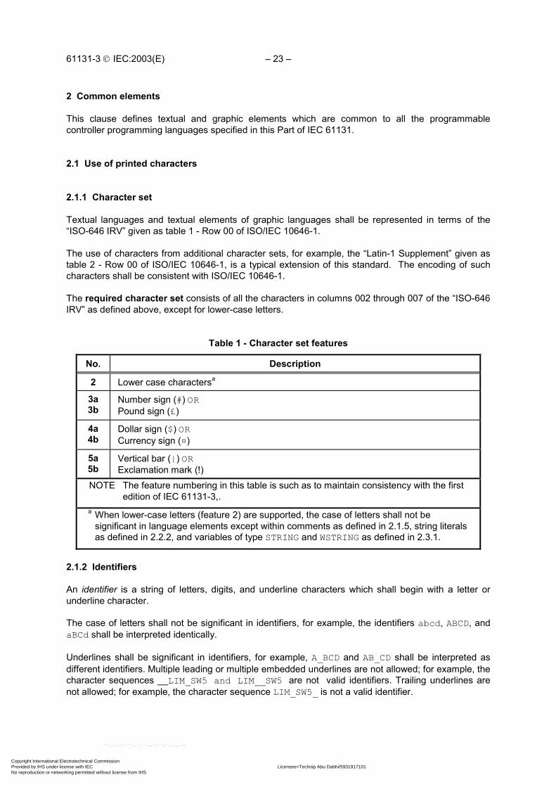
61131-3 IEC:2003(E) – 23 –
2 Common elements
This clause defines textual and graphic elements which are common to all the programmablecontroller programming languages specified in this Part of IEC 61131.
2.1 Use of printed characters
2.1.1 Character set
Textual languages and textual elements of graphic languages shall be represented in terms of the“ISO-646 IRV” given as table 1 - Row 00 of ISO/IEC 10646-1.
The use of characters from additional character sets, for example, the “Latin-1 Supplement” given astable 2 - Row 00 of ISO/IEC 10646-1, is a typical extension of this standard. The encoding of suchcharacters shall be consistent with ISO/IEC 10646-1.
The required character set consists of all the characters in columns 002 through 007 of the “ISO-646IRV” as defined above, except for lower-case letters.
Table 1 - Character set features
No. Description
2 Lower case charactersa
3a3b
Number sign (#) ORPound sign (£)
4a4b
Dollar sign ($) ORCurrency sign (¤)
5a5b
Vertical bar (|) ORExclamation mark (!)
NOTE The feature numbering in this table is such as to maintain consistency with the firstedition of IEC 61131-3,.
a When lower-case letters (feature 2) are supported, the case of letters shall not besignificant in language elements except within comments as defined in 2.1.5, string literalsas defined in 2.2.2, and variables of type STRING and WSTRING as defined in 2.3.1.
2.1.2 Identifiers
An identifier is a string of letters, digits, and underline characters which shall begin with a letter orunderline character.
The case of letters shall not be significant in identifiers, for example, the identifiers abcd, ABCD, andaBCd shall be interpreted identically.
Underlines shall be significant in identifiers, for example, A_BCD and AB_CD shall be interpreted asdifferent identifiers. Multiple leading or multiple embedded underlines are not allowed; for example, thecharacter sequences __LIM_SW5 and LIM__SW5 are not valid identifiers. Trailing underlines arenot allowed; for example, the character sequence LIM_SW5_ is not a valid identifier.
Copyright International Electrotechnical Commission Provided by IHS under license with IEC Licensee=Technip Abu Dabhi/5931917101
Not for Resale, 02/12/2006 07:01:30 MSTNo reproduction or networking permitted without license from IHS
--``,`,`,,,``````,,``,,``,,,,`,-`-`,,`,,`,`,,`---

– 24 – 61131-3 IEC:2003(E)
At least six characters of uniqueness shall be supported in all systems which support the use ofidentifiers, for example, ABCDE1 shall be interpreted as different from ABCDE2 in all such systems. Themaximum number of characters allowed in an identifier is an implementation-dependent parameter.
Identifier features and examples are shown in table 2.
Table 2 - Identifier features
No. Feature description Examples
1 Upper case and numbers IW215 IW215Z QX75 IDENT
2 Upper and lower case, numbers,embedded underlines
All the above plus:LIM_SW_5 LimSw5 abcd ab_Cd
3 Upper and lower case, numbers,leading or embedded underlines
All the above plus: _MAIN _12V7
2.1.3 Keywords
Keywords are unique combinations of characters utilized as individual syntactic elements as defined inannex B. All keywords used in this standard are listed in annex C. Keywords shall not containimbedded spaces. The case of characters shall not be significant in keywords; for instance, thekeywords “FOR” and “for” are syntactically equivalent. The keywords listed in annex C shall not beused for any other purpose, for example, variable names or extensions as defined in 1.5.1.
NOTE National standards organizations can publish tables of translations of the keywords giveninannex C.
2.1.4 Use of white space
The user shall be allowed to insert one or more characters of “white space” anywhere in the text ofprogrammable controller programs except within keywords, literals, enumerated values, identifiers,directly represented variables as described in subclause 2.4.1.1, or delimiter combinations (forexample, for comments as defined in 2.1.5). “White space” is defined as the SPACE character withencoded value 32 decimal, as well as non-printing characters such as tab, newline, etc. for which noencoding is given in IEC/ISO 10646-1.
2.1.5 Comments
User comments shall be delimited at the beginning and end by the special character combinations“(*” and “*)”, respectively, as shown in table 3. Comments shall be permitted anywhere in theprogram where spaces are allowed, except within character string literals as defined in 2.2.2.Comments shall have no syntactic or semantic significance in any of the languages defined in thisstandard.
The use of nested comments, for example, (* (* NESTED *) *), shall be treated as an erroraccording to the provisions of 1.5.1 d).
The maximum number of characters allowed in a comment is an implementation-dependentparameter.
Copyright International Electrotechnical Commission Provided by IHS under license with IEC Licensee=Technip Abu Dabhi/5931917101
Not for Resale, 02/12/2006 07:01:30 MSTNo reproduction or networking permitted without license from IHS
--``,`,`,,,``````,,``,,``,,,,`,-`-`,,`,,`,`,,`---

61131-3 IEC:2003(E) – 25 –
Table 3 - Comment feature
No. Feature description Example
1 Comments (*****************************)(* A framed comment *)(*****************************)
NOTE The example given above represents three separate comments.
2.1.6 Pragmas
As illustrated in table 3 a), pragmas shall be delimited at the beginning and end by curly brackets "{"and "}", respectively. The syntax and semantics of particular pragma constructions areimplementation dependent. Pragmas shall be permitted anywhere in the program where spaces areallowed, except within character string literals as defined in 2.2.2.
NOTE Curly brackets inside a comment have no semantic meaning; comments inside curlybrackets may or may not have semantic meaning depending on the implementation.
Table 3 a) - Pragma feature
No. Feature description Examples
1 Pragmas {VERSION 3.1}{AUTHOR JHC}{x := 256, y := 384}
2.2 External representation of data
External representations of data in the various programmable controller programming languages shallconsist of numeric literals, character strings, and time literals.
2.2.1 Numeric literals
There are two classes of numeric literals: integer literals and real literals. A numeric literal is definedas a decimal number or a based number. The maximum number of digits for each kind of numericliteral shall be sufficient to express the entire range and precision of values of all the data types whichare represented by the literal in a given implementation.
Single underline characters ( _ ) inserted between the digits of a numeric literal shall not be significant.No other use of underline characters in numeric literals is allowed.
Decimal literals shall be represented in conventional decimal notation. Real literals shall bedistinguished by the presence of a decimal point. An exponent indicates the integer power of ten bywhich the preceding number is to be multiplied to obtain the value represented. Decimal literals andtheir exponents can contain a preceding sign (+ or -).
Integer literals can also be represented in base 2, 8, or 16. The base shall be in decimal notation. Forbase 16, an extended set of digits consisting of the letters A through F shall be used, with theconventional significance of decimal 10 through 15, respectively. Based numbers shall notcontain a leading sign (+ or -).
Copyright International Electrotechnical Commission Provided by IHS under license with IEC Licensee=Technip Abu Dabhi/5931917101
Not for Resale, 02/12/2006 07:01:30 MSTNo reproduction or networking permitted without license from IHS
--``,`,`,,,``````,,``,,``,,,,`,-`-`,,`,,`,`,,`---

– 26 – 61131-3 IEC:2003(E)
Boolean data shall be represented by integer literals with the value zero (0) or one (1), or thekeywords FALSE or TRUE, respectively.
Numeric literal features and examples are shown in table 4.
The data type of a boolean or numeric literal can be specified by adding a type prefix to the literal,consisting of the name of an elementary data type and the '#' sign. For examples see feature 9 intable 4.
Table 4 - Numeric literals
No. Feature description Examples
1 Integer literals -12 0 123_456 +986
2 Real literals -12.0 0.0 0.4560 3.14159_26
3 Real literals with exponents-1.34E-12 or -1.34e-121.0E+6 or 1.0e+61.234E6 or 1.234e6
4 Base 2 literals 2#1111_1111 (255 decimal)2#1110_0000 (224 decimal)
5 Base 8 literals 8#377 (255 decimal)8#340 (224 decimal)
6 Base 16 literals 16#FF or 16#ff (255 decimal)16#E0 or 16#e0 (224 decimal)
7 Boolean zero and one 0 1
8 Boolean FALSE and TRUE FALSE TRUE
9 Typed literals DINT#5 (DINT representation of 5)
UINT#16#9AF (UINT representation of the hexadecimal value 9AF )
BOOL#0 BOOL#1 BOOL#TRUE BOOL#FALSE
NOTE The keywords FALSE and TRUE correspond to Boolean values of 0 and 1, respectively.
2.2.2 Character string literals
Character string literals include single-byte or double-byte encoded characters.
A single-byte character string literal is a sequence of zero or more characters from Row 00 of theISO/IEC 10646-1 character set prefixed and terminated by the single quote character ('). In single-byte character strings, the three-character combination of the dollar sign ($) followed by twohexadecimal digits shall be interpreted as the hexadecimal representation of the eight-bit charactercode, as shown in feature 1 of table 5.
A double-byte character string literal is a sequence of zero or more characters from the ISO/IEC10646-1 character set prefixed and terminated by the double quote character ("). In double-bytecharacter strings, the five-character combination of the dollar sign ($) followed by four hexadecimaldigits shall be interpreted as the hexadecimal representation of the sixteen-bit character code, asshown in feature 2 of table 5.
Two-character combinations beginning with the dollar sign shall be interpreted as shown in table 6when they occur in character strings.
Copyright International Electrotechnical Commission Provided by IHS under license with IEC Licensee=Technip Abu Dabhi/5931917101
Not for Resale, 02/12/2006 07:01:30 MSTNo reproduction or networking permitted without license from IHS
--``,`,`,,,``````,,``,,``,,,,`,-`-`,,`,,`,`,,`---

61131-3 IEC:2003(E) – 27 –
Table 5 - Character string literal features
No. Example Explanation
1 Single-byte character strings
'' Empty string (length zero)
'A' String of length one containing the single character A
' ' String of length one containing the “space” character
'$'' String of length one containing the “single quote” character
'"' String of length one containing the “double quote” character
'$R$L' String of length two containing CR and LF characters
'$0A' String of length one containing the LF character
'$$1.00' String of length five which would print as “$1.00”
'ÄË''$C4$CB'
Equivalent strings of length two
2 Double-byte character strings
"" Empty string (length zero)
"A" String of length one containing the single character A
" " String of length one containing the “space” character
"'" String of length one containing the “single quote” character
"$"" String of length one containing the “double quote” character
"$R$L" String of length two containing CR and LF characters
"$$1.00" String of length five which would print as “$1.00”
"ÄË""$00C4$00CB"
Equivalent strings of length two
3 Single-byte typed string literals
STRING#'OK' String of length two containing two single-byte characters
4 Double-byte typed string literals
WSTRING#'OK' String of length two containing two double-byte characters
NOTE If a particular implementation supports feature #4 but not feature #2, theimplementor may specify implementation-dependent syntax and semantics forthe use of the double-quote character.
Copyright International Electrotechnical Commission Provided by IHS under license with IEC Licensee=Technip Abu Dabhi/5931917101
Not for Resale, 02/12/2006 07:01:30 MSTNo reproduction or networking permitted without license from IHS
--``,`,`,,,``````,,``,,``,,,,`,-`-`,,`,,`,`,,`---

– 28 – 61131-3 IEC:2003(E)
Table 6 - Two-character combinations in character strings
No. Combination Interpretation when printed
2 $$ Dollar sign
3 $' Single quote
4 $L or $l Line feed
5 $N or $n Newline
6 $P or $p Form feed (page)
7 $R or $r Carriage return
8 $T or $t Tab
9 $" Double quoteNOTE 1 The “newline” character provides an implementation-independent means of defining
the end of a line of data for both physical and file I/O; for printing, the effect is that ofending a line of data and resuming printing at the beginning of the next line.
NOTE 2 The $' combination is only valid inside single quoted string literals.
NOTE 3 The $" combination is only valid inside double quoted string literals.
2.2.3 Time literals
The need to provide external representations for two distinct types of time-related data is recognized:duration data for measuring or controlling the elapsed time of a control event, and time of day data(which may also include date information) for synchronizing the beginning or end of a control event toan absolute time reference.
Duration and time of day literals shall be delimited on the left by the keywords defined in 2.2.3.1 and2.2.3.2.
2.2.3.1 Duration
Duration data shall be delimited on the left by the keyword T# or TIME#. The representation ofduration data in terms of days, hours, minutes, seconds, and milliseconds, or any combination thereof,shall be supported as shown in table 7. The least significant time unit can be written in real notationwithout an exponent.
The units of duration literals can be separated by underline characters.
“Overflow” of the most significant unit of a duration literal is permitted, for example, the notationT#25h_15m is permitted.
Time units, for example, seconds, milliseconds, etc., can be represented in upper- or lower- caseletters.
As illustrated in table 7, both positive and negative values are allowed for durations.
Copyright International Electrotechnical Commission Provided by IHS under license with IEC Licensee=Technip Abu Dabhi/5931917101
Not for Resale, 02/12/2006 07:01:30 MSTNo reproduction or networking permitted without license from IHS
--``,`,`,,,``````,,``,,``,,,,`,-`-`,,`,,`,`,,`---

61131-3 IEC:2003(E) – 29 –
Table 7 - Duration literal features
No. Feature description Examples
1aDuration literals without underlines:
short prefixT#14ms T#-14ms T#14.7s T#14.7mT#14.7h t#14.7d t#25h15mt#5d14h12m18s3.5ms
1b long prefix TIME#14ms TIME#-14ms time#14.7s
2aDuration literals with underlines:
short prefix t#25h_15m t#5d_14h_12m_18s_3.5ms
2b long prefix TIME#25h_15mtime#5d_14h_12m_18s_3.5ms
2.2.3.2 Time of day and date
Prefix keywords for time of day and date literals shall be as shown in table 8. As illustrated in table 9,representation of time-of-day and date information shall be as specified by the syntax given inB.1.2.3.2.
Table 8 - Date and time of day literals
No. Feature description Prefix Keyword
1 Date literals (long prefix) DATE#
2 Date literals (short prefix) D#
3 Time of day literals (long prefix) TIME_OF_DAY#
4 Time of day literals (short prefix) TOD#
5 Date and time literals (long prefix) DATE_AND_TIME#
6 Date and time literals (short prefix) DT#
Table 9 - Examples of date and time of day literals
Long prefix notation Short prefix notation
DATE#1984-06-25date#1984-06-25
D#1984-06-25d#1984-06-25
TIME_OF_DAY#15:36:55.36time_of_day#15:36:55.36
TOD#15:36:55.36tod#15:36:55.36
DATE_AND_TIME#1984-06-25-15:36:55.36date_and_time#1984-06-25-15:36:55.36
DT#1984-06-25-15:36:55.36dt#1984-06-25-15:36:55.36
2.3 Data types
A number of elementary (pre-defined) data types are recognized by this standard. Additionally,generic data types are defined for use in the definition of overloaded functions (see 2.5.1.4). Amechanism for the user or manufacturer to specify additional data types is also defined.
Copyright International Electrotechnical Commission Provided by IHS under license with IEC Licensee=Technip Abu Dabhi/5931917101
Not for Resale, 02/12/2006 07:01:30 MSTNo reproduction or networking permitted without license from IHS
--``,`,`,,,``````,,``,,``,,,,`,-`-`,,`,,`,`,,`---

– 30 – 61131-3 IEC:2003(E)
2.3.1 Elementary data types
The elementary data types, keyword for each data type, number of bits per data element, and rangeof values for each elementary data type shall be as shown in table 10.
Table 10 - Elementary data types
No. Keyword Data type N a
1 BOOL Boolean 1 h
2 SINT Short integer 8 c
3 INT Integer 16 c
4 DINT Double integer 32 c
5 LINT Long integer 64 c
6 USINT Unsigned short integer 8 d
7 UINT Unsigned integer 16 d
8 UDINT Unsigned double integer 32 d
9 ULINT Unsigned long integer 64 d
10 REAL Real numbers 32 e
11 LREAL Long reals 64 f
12 TIME Duration -- b
13 DATE Date (only) -- b
14 TIME_OF_DAY or TOD Time of day (only) -- b
15 DATE_AND_TIME or DT Date and time of Day -- b
16 STRING Variable-length single-byte character string 8 i,g
17 BYTE Bit string of length 8 8 j,g
18 WORD Bit string of length 16 16 j,g
19 DWORD Bit string of length 32 32 j,g
20 LWORD Bit string of length 64 64 j,g
21 WSTRING Variable-length double-byte character string 16 i,g
Copyright International Electrotechnical Commission Provided by IHS under license with IEC Licensee=Technip Abu Dabhi/5931917101
Not for Resale, 02/12/2006 07:01:30 MSTNo reproduction or networking permitted without license from IHS
--``,`,`,,,``````,,``,,``,,,,`,-`-`,,`,,`,`,,`---

61131-3 IEC:2003(E) – 31 –
Table 10 - Elementary data typesa Entries in this column shall be interpreted as specified in the footnotes.b The range of values and precision of representation in these data types is implementation-
dependent.c The range of values for variables of this data type is from -(2N-1) to (2N-1)-1.d The range of values for variables of this data type is from 0 to (2N)-1.e The range of values for variables of this data type shall be as defined in IEC 60559 for the
basic single width floating-point format.f The range of values for variables of this data type shall be as defined in IEC 60559 for the
basic double width floating-point format.g A numeric range of values does not apply to this data type.h The possible values of variables of this data type shall be 0 and 1, corresponding to the
keywords FALSE and TRUE, respectively.i The value of N indicates the number of bits/character for this data type.j The value of N indicates the number of bits in the bit string for this data type.
2.3.2 Generic data types
In addition to the data types shown in table 10, the hierarchy of generic data types shown in table 11can be used in the specification of inputs and outputs of standard functions and function blocks (seesubclause 2.5.1.4). Generic data types are identified by the prefix “ANY”. The use of generic datatypes is subject to the following rules:
1) Generic data types shall not be used in user-declared program organization units as defined in2.5.
2) The generic type of a subrange derived type (feature 3 of table 12) shall be ANY_INT.
3) The generic type of a directly derived type (feature 1 of table 12) shall be the same as the generictype of the elementary type from which it is derived.
4) The generic type of all other derived types defined in table 12 shall be ANY_DERIVED.
Copyright International Electrotechnical Commission Provided by IHS under license with IEC Licensee=Technip Abu Dabhi/5931917101
Not for Resale, 02/12/2006 07:01:30 MSTNo reproduction or networking permitted without license from IHS
--``,`,`,,,``````,,``,,``,,,,`,-`-`,,`,,`,`,,`---

– 32 – 61131-3 IEC:2003(E)
Table 11 - Hierarchy of generic data types
ANY ANY_DERIVED (Derived data types - see preceding text) ANY_ELEMENTARY ANY_MAGNITUDE ANY_NUM ANY_REAL LREAL REAL ANY_INT LINT, DINT, INT, SINT ULINT, UDINT, UINT, USINT TIME ANY_BIT LWORD, DWORD, WORD, BYTE, BOOL ANY_STRING STRING WSTRING ANY_DATE DATE_AND_TIME DATE, TIME_OF_DAY
2.3.3 Derived data types
2.3.3.1 Declaration
Derived (i.e., user- or manufacturer-specified) data types can be declared using theTYPE...END_TYPE textual construction shown in table 12. These derived data types can then beused, in addition to the elementary data types defined in 2.3.1, in variable declarations as defined in2.4.3.
An enumerated data type declaration specifies that the value of any data element of that type can onlytake on one of the values given in the associated list of identifiers, as illustrated in table 12. Theenumeration list defines an ordered set of enumerated values, starting with the first identifier of the list,and ending with the last. Different enumerated data types may use the same identifiers forenumerated values. The maximum allowed number of enumerated values is an implementation-dependent parameter.
To enable unique identification when used in a particular context, enumerated literals may be qualifiedby a prefix consisting of their associated data type name and the '#' sign, similar to typed literalsdefined in 2.2.1. Such a prefix shall not be used inside an enumeration list. It is an error if sufficientinformation is not provided in an enumerated literal to determine its value unambiguously.
A subrange declaration specifies that the value of any data element of that type can only take onvalues between and including the specified upper and lower limits, as illustrated in table 12. It is anerror if the value of a value of a subrange type falls outside the specified range of values.
A STRUCT declaration specifies that data elements of that type shall contain sub-elements of specifiedtypes which can be accessed by the specified names. For instance, an element of data typeANALOG_CHANNEL_CONFIGURATION as declared in table 12 will contain a RANGE sub-element oftype ANALOG_SIGNAL_RANGE, a MIN_SCALE sub-element of type ANALOG_DATA, and a MAX_SCALEelement of type ANALOG_DATA. The maximum number of structure elements, the maximum amount ofdata that can be contained in a structure, and the maximum number of nested levels of structureelement addressing are implementation-dependent parameters.
Copyright International Electrotechnical Commission Provided by IHS under license with IEC Licensee=Technip Abu Dabhi/5931917101
Not for Resale, 02/12/2006 07:01:30 MSTNo reproduction or networking permitted without license from IHS
--``,`,`,,,``````,,``,,``,,,,`,-`-`,,`,,`,`,,`---

61131-3 IEC:2003(E) – 33 –
An ARRAY declaration specifies that a sufficient amount of data storage shall be allocated for eachelement of that type to store all the data which can be indexed by the specified index subrange(s).Thus, any element of type ANALOG_16_INPUT_CONFIGURATION as shown in table 12 contains(among other elements) sufficient storage for 16 CHANNEL elements of typeANALOG_CHANNEL_CONFIGURATION. Mechanisms for access to array elements are defined in2.4.1.2. The maximum number of array subscripts, maximum array size and maximum range ofsubscript values are implementation-dependent parameters.
2.3.3.2 Initialization
The default initial value of an enumerated data type shall be the first identifier in the associatedenumeration list, or a value specified by the assignment operator “:=”. For instance, as shown intable 12, No.2, and table 14, No.2, the default initial values of elements of data typesANALOG_SIGNAL_TYPE and ANALOG_SIGNAL_RANGE are SINGLE_ENDED and UNIPOLAR_1_5V,respectively.
For data types with subranges, the default initial values shall be the first (lower) limit of the subrange,unless otherwise specified by an assignment operator. For instance, as declared in table 12, thedefault initial value of elements of type ANALOG_DATA is -4095, while the default initial value for theFILTER_PARAMETER sub-element of elements of type ANALOG_16_INPUT_CONFIGURATION is zero.In contrast, the default initial value of elements of type ANALOG_DATAZ as declared in table 14 is zero.
For other derived data types, the default initial values, unless specified otherwise by the use of theassignment operator “:=” in the TYPE declaration, shall be the default initial values of the underlyingelementary data types as defined in table 13. Further examples of the use of the assignment operatorfor initialization are given in 2.4.2.
The default maximum length of elements of type STRING and WSTRING shall be an implementation-dependent value unless specified otherwise by a parenthesized maximum length (which shall notexceed the implementation-dependent default value) in the associated declaration. For example, iftype STR10 is declared by
TYPE STR10 : STRING[10] := 'ABCDEF'; END_TYPE
the maximum length, default initial value, and default initial length of data elements of type STR10 are10 characters, 'ABCDEF', and 6 characters, respectively. The maximum allowed length of STRINGand WSTRING variables is an implementation-dependent parameter.
Table 12 - Data type declaration features
No. Feature/textual example
1 Direct derivation from elementary types, e.g.:TYPE RU_REAL : REAL ; END_TYPE
2 Enumerated data types, e.g.:TYPE ANALOG_SIGNAL_TYPE : (SINGLE_ENDED, DIFFERENTIAL) ; END_TYPE
3 Subrange data types, e.g.:TYPE ANALOG_DATA : INT (-4095..4095) ; END_TYPE
4 Array data types, e.g.:TYPE ANALOG_16_INPUT_DATA : ARRAY [1..16] OF ANALOG_DATA ; END_TYPE
Copyright International Electrotechnical Commission Provided by IHS under license with IEC Licensee=Technip Abu Dabhi/5931917101
Not for Resale, 02/12/2006 07:01:30 MSTNo reproduction or networking permitted without license from IHS
--``,`,`,,,``````,,``,,``,,,,`,-`-`,,`,,`,`,,`---

– 34 – 61131-3 IEC:2003(E)
Table 12 - Data type declaration features
No. Feature/textual example
5 Structured data types, e.g.:TYPE ANALOG_CHANNEL_CONFIGURATION : STRUCT RANGE : ANALOG_SIGNAL_RANGE ; MIN_SCALE : ANALOG_DATA ; MAX_SCALE : ANALOG_DATA ; END_STRUCT ; ANALOG_16_INPUT_CONFIGURATION : STRUCT SIGNAL_TYPE : ANALOG_SIGNAL_TYPE ; FILTER_PARAMETER : SINT (0..99) ; CHANNEL : ARRAY [1..16] OF ANALOG_CHANNEL_CONFIGURATION ; END_STRUCT ;END_TYPE
NOTE For examples of the use of these types in variable declarations, see 2.3.3.3, 2.4.1.2, andtable 17.
Table 13 - Default initial values of elementary data types
Data type(s) Initial value
BOOL, SINT, INT, DINT, LINT 0
USINT, UINT, UDINT, ULINT 0
BYTE, WORD, DWORD, LWORD 0
REAL, LREAL 0.0
TIME T#0S
DATE D#0001-01-01
TIME_OF_DAY TOD#00:00:00
DATE_AND_TIME DT#0001-01-01-00:00:00
STRING '' (the empty string)
WSTRING "" (the empty string)
Copyright International Electrotechnical Commission Provided by IHS under license with IEC Licensee=Technip Abu Dabhi/5931917101
Not for Resale, 02/12/2006 07:01:30 MSTNo reproduction or networking permitted without license from IHS
--``,`,`,,,``````,,``,,``,,,,`,-`-`,,`,,`,`,,`---

61131-3 IEC:2003(E) – 35 –
Table 14 - Data type initial value declaration features
No. Feature/textual example
1 Initialization of directly derived types, e.g.:TYPE FREQ : REAL := 50.0 ; END_TYPE
2 Initialization of enumerated data types, e.g.:TYPE ANALOG_SIGNAL_RANGE : (BIPOLAR_10V, (* -10 to +10 VDC *) UNIPOLAR_10V, (* 0 to +10 VDC *) UNIPOLAR_1_5V, (* + 1 to + 5 VDC *) UNIPOLAR_0_5V, (* 0 to + 5 VDC *) UNIPOLAR_4_20_MA, (* + 4 to +20 mADC *) UNIPOLAR_0_20_MA (* 0 to +20 mADC *) ) := UNIPOLAR_1_5V ;END_TYPE
3 Initialization of subrange data types, e.g.:TYPE ANALOG_DATAZ : INT (-4095..4095) := 0 ; END_TYPE
4 Initialization of array data types, e.g.:TYPE ANALOG_16_INPUT_DATAI : ARRAY [1..16] OF ANALOG_DATA := [8(-4095), 8(4095)] ;END_TYPE
5 Initialization of structured data type elements, e.g.:TYPE ANALOG_CHANNEL_CONFIGURATIONI : STRUCT RANGE : ANALOG_SIGNAL_RANGE ; MIN_SCALE : ANALOG_DATA := -4095 ; MAX_SCALE : ANALOG_DATA := 4095 ; END_STRUCT ;END_TYPE
6 Initialization of derived structured data types, e.g.:TYPE ANALOG_CHANNEL_CONFIGZ : ANALOG_CHANNEL_CONFIGURATIONI := (MIN_SCALE := 0, MAX_SCALE := 4000);END_TYPE
2.3.3.3 Usage
The usage of variables which are declared (as defined in 2.4.3.1) to be of derived data types shallconform to the following rules:
1) A single-element variable, as defined in 2.4.1.1, of a derived type, can be used anywhere that avariable of its “parent's” type can be used, for example variables of the types RU_REAL andFREQ as shown in tables 12 and 14 can be used anywhere that a variable of type REAL couldbe used, and variables of type ANALOG_DATA can be used anywhere that a variable of type INTcould be used.
This rule can be applied recursively. For example, given the declarations below, the variable R3of type R2 can be used anywhere a variable of type REAL can be used:
TYPE R1 : REAL := 1.0 ; END_TYPETYPE R2 : R1 ; END_TYPEVAR R3: R2; END_VAR
Copyright International Electrotechnical Commission Provided by IHS under license with IEC Licensee=Technip Abu Dabhi/5931917101
Not for Resale, 02/12/2006 07:01:30 MSTNo reproduction or networking permitted without license from IHS
--``,`,`,,,``````,,``,,``,,,,`,-`-`,,`,,`,`,,`---

– 36 – 61131-3 IEC:2003(E)
2) An element of a multi-element variable, as defined in 2.4.1.2, can be used anywhere the“parent” type can be used, for example, given the declaration of ANALOG_16_INPUT_DATA intable 12 and the declaration
VAR INS : ANALOG_16_INPUT_DATA ; END_VAR
the variables INS[1] through INS[16] can be used anywhere that a variable of type INTcould be used.
This rule can also be applied recursively, for example, given the declarations ofANALOG_16_INPUT_CONFIGURATION, ANALOG_CHANNEL_CONFIGURATION, and ANALOG_-DATA in table 12 and the declaration
VAR CONF : ANALOG_16_INPUT_CONFIGURATION ; END_VAR
the variable CONF.CHANNEL[2].MIN_SCALE can be used anywhere that a variable of typeINT could be used.
2.4 Variables
In contrast to the external representations of data described in 2.2, variables provide a means ofidentifying data objects whose contents may change, for example, data associated with the inputs,outputs, or memory of the programmable controller. A variable can be declared to be one of theelementary types defined in 2.3.1, or one of the derived types which are declared as defined in2.3.3.1.
2.4.1 Representation
2.4.1.1 Single-element variables
A single-element variable is defined as a variable which represents a single data element of one of theelementary types defined in 2.3.1; a derived enumeration or subrange type as defined in 2.3.3.1; or aderived type whose “parentage”, as defined recursively in 2.3.3.3, is traceable to an elementary,enumeration or subrange type. This subclause defines the means of representing such variablessymbolically, or alternatively in a manner which directly represents the association of the data elementwith physical or logical locations in the programmable controller's input, output, or memory structure.
Identifiers, as defined in 2.1.2, shall be used for symbolic representation of variables.
Direct representation of a single-element variable shall be provided by a special symbol formed bythe concatenation of the percent sign “%” (character code 037 decimal in table 1 - Row 00 of ISO/IEC10646-1), a location prefix and a size prefix from table 15, and one or more unsigned integers,separated by periods (.).
In the case that a directly represented variable is used in a location assignment to an internal variablein the declaration part of a program or a function block type as defined in 2.4.3.1, an asterisk “*” shallbe used in place of the size prefix and the one or several unsigned integers in the concatenation toindicate that the direct representation is not yet fully specified. The percent sign and the location prefixI, Q or M from table 15 shall always be present in the direct representation.
In both cases, the use of this feature requires that the location of the variable so declared shall be fullyspecified inside the VAR_CONFIG...END_VAR construction of the configuration as defined in 2.7.1 forevery instance of the containing type.
It is an error if any of the full specifications in the VAR_CONFIG...END_VAR construction is missingfor any incomplete address specification expressed by the asterisk notation in any instance ofprograms or function block types which contain such incomplete specifications.
Copyright International Electrotechnical Commission Provided by IHS under license with IEC Licensee=Technip Abu Dabhi/5931917101
Not for Resale, 02/12/2006 07:01:30 MSTNo reproduction or networking permitted without license from IHS
--``,`,`,,,``````,,``,,``,,,,`,-`-`,,`,,`,`,,`---

61131-3 IEC:2003(E) – 37 –
EXAMPLES
%QX75 and %Q75 Output bit 75
%IW215 Input word location 215
%QB7 Output byte location 7
%MD48 Double word at memory location 48
%IW2.5.7.1 See explanation below
%Q* Output at a not yet specified location
The manufacturer shall specify the correspondence between the direct representation of a variableand the physical or logical location of the addressed item in memory, input or output. When a directrepresentation is extended with additional integer fields separated by periods, it shall be interpreted asa hierarchical physical or logical address with the leftmost field representing the highest level of thehierarchy, with successively lower levels appearing to the right. For instance, the variable%IW2.5.7.1 may represent the first “channel” (word) of the seventh “module” in the fifth “rack” of thesecond “I/O bus” of a programmable controller system.
The use of hierarchical addressing to permit a program in one programmable controller system toaccess data in another programmable controller shall be considered a language extension.
The use of directly represented variables is permitted in function blocks as defined in 2.5.2, programsas defined in 2.5.3, and in configurations and resources as defined in 2.7.1. The maximum number oflevels of hierarchical addressing is an implementation-dependent parameter.
Table 15 - Location and size prefix features for directly represented variables
No. Prefix Meaning Default data type
1 I Input location
2 Q Output location
3 M Memory location
4 X Single bit size BOOL
5 None Single bit size BOOL
6 B Byte (8 bits) size BYTE
7 W Word (16 bits) size WORD
8 D Double word (32 bits)size
DWORD
9 L Long (quad) word (64bits) size
LWORD
10 Use of an asterisk (*) to indicate a not yet specifiedlocation (NOTE 2)
NOTE 1 National standards organizations can publish tables of translations of theseprefixes.
NOTE 2 Use of feature 10 in this table requires feature 11 of table 49 and vice versa.
Copyright International Electrotechnical Commission Provided by IHS under license with IEC Licensee=Technip Abu Dabhi/5931917101
Not for Resale, 02/12/2006 07:01:30 MSTNo reproduction or networking permitted without license from IHS
--``,`,`,,,``````,,``,,``,,,,`,-`-`,,`,,`,`,,`---

– 38 – 61131-3 IEC:2003(E)
2.4.1.2 Multi-element variables
The multi-element variable types defined in this standard are arrays and structures.
An array is a collection of data elements of the same data type referenced by one or more subscriptsenclosed in brackets and separated by commas. In the ST language defined in subclause 3.3, asubscript shall be an expression yielding a value corresponding to one of the sub-types of generic typeANY_INT as defined in table 11. The form of subscripts in the IL language defined in 3.2, and thegraphic languages defined in clause 4, is restricted to single-element variables or integer literals.
An example of the use of array variables in the ST language as defined in 3.3 is:
OUTARY[%MB6,SYM] := INARY[0] + INARY[7] - INARY[%MB6] * %IW62 ;
A structured variable is a variable which is declared to be of a type which has previously beenspecified to be a data structure, i.e., a data type consisting of a collection of named elements.
An element of a structured variable shall be represented by two or more identifiers or array accessesseparated by single periods (.). The first identifier represents the name of the structured element, andsubsequent identifiers represent the sequence of component names to access the particular dataelement within the data structure.
For instance, if the variable MODULE_5_CONFIG has been declared to be of typeANALOG_16_INPUT_CONFIGURATION as shown in table 12, the following statements in the STlanguage defined in 3.3 would cause the value SINGLE_ENDED to be assigned to the elementSIGNAL_TYPE of the variable MODULE_5_CONFIG, while the value BIPOLAR_10V would be assignedto the RANGE sub-element of the fifth CHANNEL element of MODULE_5_CONFIG:
MODULE_5_CONFIG.SIGNAL_TYPE := SINGLE_ENDED;MODULE_5_CONFIG.CHANNEL[5].RANGE := BIPOLAR_10V;
2.4.2 Initialization
When a configuration element (resource or configuration) is “started” as defined in 1.4.1, each of thevariables associated with the configuration element and its programs can take on one of the followinginitial values:
- the value the variable had when the configuration element was “stopped” (a retained value);- a user-specified initial value;- the default initial value for the variable's associated data type.
The user can declare that a variable is to be retentive by using the RETAIN qualifier specified intable 16 a), when this feature is supported by the implementation.
The initial value of a variable upon starting of its associated configuration element shall be determinedaccording to the following rules:
1) If the starting operation is a “warm restart” as defined in IEC 61131-1, the initial values of retentivevariables shall be their retained values as defined above.
2) If the operation is a “cold restart” as defined in IEC 61131-1, the initial values of retentive variablesshall be the user-specified initial values, or the default value, as defined in 2.3.3.2, for theassociated data type of any variable for which no initial value is specified by the user.
3) Non-retained variables shall be initialized to the user-specified initial values, or to the default value,as defined in 2.3.3.2, for the associated data type of any variable for which no initial value isspecified by the user.
4) Variables which represent inputs of the programmable controller system as defined in IEC 61131-1shall be initialized in an implementation-dependent manner.
Copyright International Electrotechnical Commission Provided by IHS under license with IEC Licensee=Technip Abu Dabhi/5931917101
Not for Resale, 02/12/2006 07:01:30 MSTNo reproduction or networking permitted without license from IHS
--``,`,`,,,``````,,``,,``,,,,`,-`-`,,`,,`,`,,`---
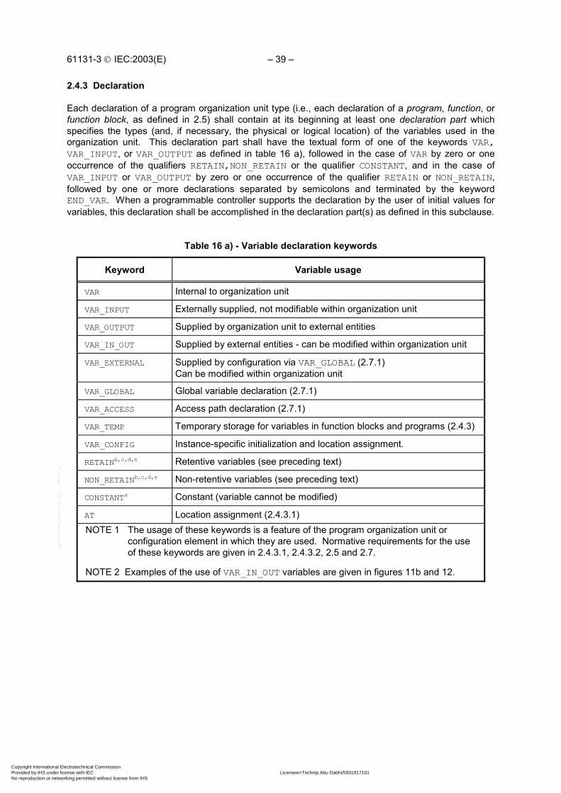
61131-3 IEC:2003(E) – 39 –
2.4.3 Declaration
Each declaration of a program organization unit type (i.e., each declaration of a program, function, orfunction block, as defined in 2.5) shall contain at its beginning at least one declaration part whichspecifies the types (and, if necessary, the physical or logical location) of the variables used in theorganization unit. This declaration part shall have the textual form of one of the keywords VAR,VAR_INPUT, or VAR_OUTPUT as defined in table 16 a), followed in the case of VAR by zero or oneoccurrence of the qualifiers RETAIN,NON_RETAIN or the qualifier CONSTANT, and in the case ofVAR_INPUT or VAR_OUTPUT by zero or one occurrence of the qualifier RETAIN or NON_RETAIN,followed by one or more declarations separated by semicolons and terminated by the keywordEND_VAR. When a programmable controller supports the declaration by the user of initial values forvariables, this declaration shall be accomplished in the declaration part(s) as defined in this subclause.
Table 16 a) - Variable declaration keywords
Keyword Variable usage
VAR Internal to organization unit
VAR_INPUT Externally supplied, not modifiable within organization unit
VAR_OUTPUT Supplied by organization unit to external entities
VAR_IN_OUT Supplied by external entities - can be modified within organization unit
VAR_EXTERNAL Supplied by configuration via VAR_GLOBAL (2.7.1)Can be modified within organization unit
VAR_GLOBAL Global variable declaration (2.7.1)
VAR_ACCESS Access path declaration (2.7.1)
VAR_TEMP Temporary storage for variables in function blocks and programs (2.4.3)
VAR_CONFIG Instance-specific initialization and location assignment.
RETAINb,c,d,e Retentive variables (see preceding text)
NON_RETAINb,c,d,e Non-retentive variables (see preceding text)
CONSTANTa Constant (variable cannot be modified)
AT Location assignment (2.4.3.1)NOTE 1 The usage of these keywords is a feature of the program organization unit or
configuration element in which they are used. Normative requirements for the useof these keywords are given in 2.4.3.1, 2.4.3.2, 2.5 and 2.7.
NOTE 2 Examples of the use of VAR_IN_OUT variables are given in figures 11b and 12.
Copyright International Electrotechnical Commission Provided by IHS under license with IEC Licensee=Technip Abu Dabhi/5931917101
Not for Resale, 02/12/2006 07:01:30 MSTNo reproduction or networking permitted without license from IHS
--``,`,`,,,``````,,``,,``,,,,`,-`-`,,`,,`,`,,`---
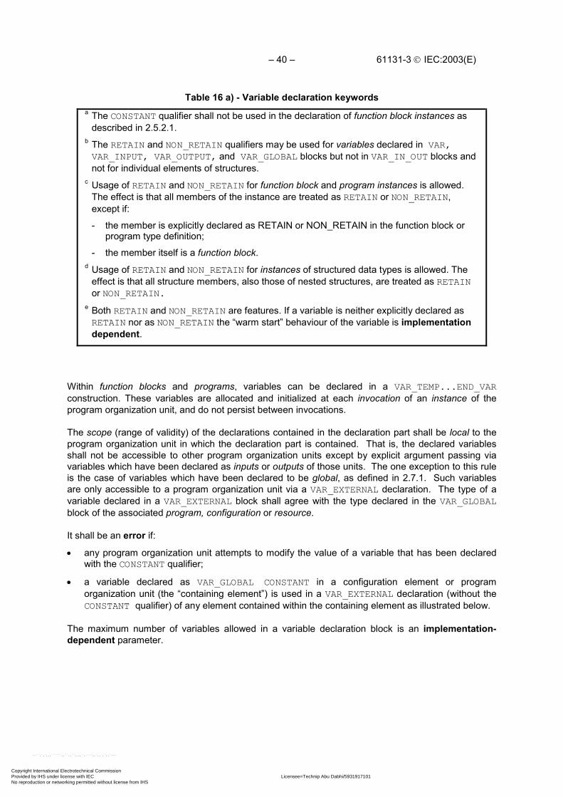
– 40 – 61131-3 IEC:2003(E)
Table 16 a) - Variable declaration keywordsa The CONSTANT qualifier shall not be used in the declaration of function block instances as
described in 2.5.2.1.b The RETAIN and NON_RETAIN qualifiers may be used for variables declared in VAR,VAR_INPUT, VAR_OUTPUT, and VAR_GLOBAL blocks but not in VAR_IN_OUT blocks andnot for individual elements of structures.
c Usage of RETAIN and NON_RETAIN for function block and program instances is allowed.The effect is that all members of the instance are treated as RETAIN or NON_RETAIN,except if:
- the member is explicitly declared as RETAIN or NON_RETAIN in the function block orprogram type definition;
- the member itself is a function block.d Usage of RETAIN and NON_RETAIN for instances of structured data types is allowed. The
effect is that all structure members, also those of nested structures, are treated as RETAINor NON_RETAIN.
e Both RETAIN and NON_RETAIN are features. If a variable is neither explicitly declared asRETAIN nor as NON_RETAIN the “warm start” behaviour of the variable is implementationdependent.
Within function blocks and programs, variables can be declared in a VAR_TEMP...END_VARconstruction. These variables are allocated and initialized at each invocation of an instance of theprogram organization unit, and do not persist between invocations.
The scope (range of validity) of the declarations contained in the declaration part shall be local to theprogram organization unit in which the declaration part is contained. That is, the declared variablesshall not be accessible to other program organization units except by explicit argument passing viavariables which have been declared as inputs or outputs of those units. The one exception to this ruleis the case of variables which have been declared to be global, as defined in 2.7.1. Such variablesare only accessible to a program organization unit via a VAR_EXTERNAL declaration. The type of avariable declared in a VAR_EXTERNAL block shall agree with the type declared in the VAR_GLOBALblock of the associated program, configuration or resource.
It shall be an error if:
• any program organization unit attempts to modify the value of a variable that has been declaredwith the CONSTANT qualifier;
• a variable declared as VAR_GLOBAL CONSTANT in a configuration element or programorganization unit (the “containing element”) is used in a VAR_EXTERNAL declaration (without theCONSTANT qualifier) of any element contained within the containing element as illustrated below.
The maximum number of variables allowed in a variable declaration block is an implementation-dependent parameter.
Copyright International Electrotechnical Commission Provided by IHS under license with IEC Licensee=Technip Abu Dabhi/5931917101
Not for Resale, 02/12/2006 07:01:30 MSTNo reproduction or networking permitted without license from IHS
--``,`,`,,,``````,,``,,``,,,,`,-`-`,,`,,`,`,,`---

61131-3 IEC:2003(E) – 41 –
Table 16 b) – Usages of VAR_GLOBAL, VAR_EXTERNAL and CONSTANT declarations
Declaration in containing element Declaration in contained element Allowed?
VAR_GLOBAL X ... VAR_EXTERNAL CONSTANT X... Yes
VAR_GLOBAL X ... VAR_EXTERNAL X... Yes
VAR_GLOBAL CONSTANT X ... VAR_EXTERNAL CONSTANT X ... Yes
VAR_GLOBAL CONSTANT X ... VAR_EXTERNAL X ... NO
2.4.3.1 Type assignment
As shown in table 17, the VAR...END_VAR construction shall be used to specify data types andretentivity for directly represented variables. This construction shall also be used to specify datatypes, retentivity, and (where necessary, in programs and VAR_GLOBAL declarations only) the physicalor logical location of symbolically represented single- or multi-element variables. The usage of theVAR_INPUT, VAR_OUTPUT, and VAR_IN_OUT constructions is defined in 2.5.
The assignment of a physical or logical address to a symbolically represented variable shall beaccomplished by the use of the AT keyword. Where no such assignment is made, automaticallocation of the variable to an appropriate location in the programmable controller memory shall beprovided.
The asterisk notation (feature No. 10 in table 15) can be used in address assignments insideprograms and function block types to denote not yet fully specified locations for directly representedvariables.
Table 17 - Variable type assignment features
No. Feature/examples
1a Declaration of directly represented variables
VAR AT %IW6.2 : WORD; AT %MW6 : INT ;END_VAR
16-bit string (note 2)16-bit integer, initial value = 0
2a Declaration of directly represented retentive variables
VAR RETAIN AT %QW5 : WORD ;END_VAR
At cold restart, will be initialized to a 16-bit string with value16#0000
3a Declaration of locations of symbolic variables
VAR_GLOBAL LIM_SW_S5 AT %IX27 : BOOL;
Assigns input bit 27 to the Boolean variableLIM_SW_5 (note 2)
CONV_START AT %QX25 : BOOL; Assigns output bit 25 to the Boolean variableCONV_START
TEMPERATURE AT %IW28: INT; Assigns input word 28 to the integer variableTEMPERATURE (note 2)
VAR C2 AT %Q* : BYTE ;END_VAR
Assigns not yet located output byte to bitstringvariable C2 of length 8 bits
Copyright International Electrotechnical Commission Provided by IHS under license with IEC Licensee=Technip Abu Dabhi/5931917101
Not for Resale, 02/12/2006 07:01:30 MSTNo reproduction or networking permitted without license from IHS
--``,`,`,,,``````,,``,,``,,,,`,-`-`,,`,,`,`,,`---

– 42 – 61131-3 IEC:2003(E)
Table 17 - Variable type assignment features
No. Feature/examples
4a Array location assignment
VARINARY AT %IW6 : ARRAY [0..9] OF INT;END_VAR
Declares an array of 10 integers to be allocated to contiguousinput locations starting at %IW6 (note 2)
5 Automatic memory allocation of symbolic variables
VAR CONDITION_RED : BOOL; IBOUNCE : WORD ;
MYDUB : DWORD ;
AWORD, BWORD, CWORD : INT;
MYSTR: STRING[10] ;END_VAR
Allocates a memory bit to the Boolean variableCONDITION_RED.Allocates a memory word to the 16-bit string variableIBOUNCE.Allocates a double memory word to the 32-bit-stringvariable MYDUB.Allocates 3 separate memory words for the integervariables AWORD, BWORD, and CWORD.Allocates memory to contain a string with amaximum length of 10 characters. After initializa-tion, the string has length 0 and contains the emptystring ''.
6 Array declaration
VAR THREE :ARRAY[1..5,1..10,1..8] OF INT;END_VAR
Allocates 400 memory words for a three-dimensional array of integers
7 Retentive array declaration
VAR RETAIN RTBT: ARRAY[1..2,1..3] OF INT;END_VAR
Declares retentive array RTBT with “coldrestart” initial values of 0 for all elements
8 Declaration of structured variables
VAR MODULE_8_CONFIG : ANALOG_16_INPUT_CONFIGURATION;END_VAR
Declaration of a variable of derived datatype (see table 12)
NOTE 1 Initialization of system inputs is implementation-dependent; see 2.4.2.
NOTE 2 The notes to table 16 a) also apply to this table.a If directly represented variables are explicitly located, features 1 to 4 can only be used inPROGRAM and VAR_GLOBAL declarations, as defined in 2.5.3 and 2.7.1, respectively. If theasterisk notation of feature 10 in table 15 is used to indicate instance specific locationassignment of a partly specified directly represented variable, features 1 and 2 can not be used,and features 3 and 4 can only be used in declarations of internal variables of function blocks andprograms, as defined in 2.5.2 and 2.5.3, respectively.
2.4.3.2 Initial value assignment
The VAR...END_VAR construction can be used as shown in table 18 to specify initial values ofdirectly represented variables or symbolically represented single- or multi-element variables.
Copyright International Electrotechnical Commission Provided by IHS under license with IEC Licensee=Technip Abu Dabhi/5931917101
Not for Resale, 02/12/2006 07:01:30 MSTNo reproduction or networking permitted without license from IHS
--``,`,`,,,``````,,``,,``,,,,`,-`-`,,`,,`,`,,`---

61131-3 IEC:2003(E) – 43 –
Initial values can also be specified by using the instance-specific initialization feature provided by theVAR_CONFIG...END_VAR construct described in 2.7.1 (table 49, feature 11). Instance-specific initialvalues always override type-specific initial values.
NOTE The usage of the VAR_INPUT, VAR_OUTPUT, and VAR_IN_OUT constructions is definedin subclause 2.5.
Initial values cannot be given in VAR_EXTERNAL declarations.
During initialization of arrays, the rightmost subscript of an array shall vary most rapidly with respect tofilling the array from the list of initialization variables.
Parentheses can be used as a repetition factor in array initialization lists, for example, 2(1,2,3) isequivalent to the initialization sequence 1,2,3,1,2,3.
If the number of initial values given in the initialization list exceeds the number of array entries, theexcess (rightmost) initial values shall be ignored. If the number of initial values is less than thenumber of array entries, the remaining array entries shall be filled with the default initial values for thecorresponding data type. In either case, the user shall be warned of this condition during preparationof the program for execution.
When a variable is declared to be of a derived, structured data type as defined in 2.3.3.1, initial valuesfor the elements of the variable can be declared in a parenthesized list following the data typeidentifier, as shown in table 18. Elements for which initial values are not listed in the initial value listshall have the default initial values declared for those elements in the data type declaration.
When a variable is declared to be a function block instance, as defined in 2.5.2.2, initial values for theinputs and any accessible variables of the function block can be declared in a parenthesized listfollowing the assignment operator that follows the function block type identifier as shown in table 18.Elements for which initial values are not listed shall have the default initial values declared for thoseelements in the function block declaration.
Table 18 - Variable initial value assignment featuresNo. Feature/examples
1 a Initialization of directly represented variablesVAR AT %QX5.1 : BOOL :=1; AT %MW6 : INT := 8 ;END_VAR
Boolean type, initial value = 1Initializes a memory word to integer 8
2 a Initialization of directly represented retentive variablesVAR RETAIN AT %QW5 : WORD := 16#FF00 ;END_VAR
At cold restart, the 8 most significant bits ofthe 16-bit string at output word 5 are to beinitialized to 1 and the 8 least significant bitsto 0
3 a Location and initial value assignment to symbolic variablesVAR VALVE_POS AT %QW28 : INT := 100;END_VAR
Assigns output word 28 to theinteger variable VALVE_POS, withan initial value of 100
4 a Array location assignment and initializationVAR OUTARY AT %QW6 : ARRAY[0..9] OF INT := [10(1)];END_VAR
Declares an array of 10 integers to beallocated to contiguous output locationsstarting at %QW6, each with an initialvalue of 1
Copyright International Electrotechnical Commission Provided by IHS under license with IEC Licensee=Technip Abu Dabhi/5931917101
Not for Resale, 02/12/2006 07:01:30 MSTNo reproduction or networking permitted without license from IHS
--``,`,`,,,``````,,``,,``,,,,`,-`-`,,`,,`,`,,`---

– 44 – 61131-3 IEC:2003(E)
Table 18 - Variable initial value assignment featuresNo. Feature/examples
5 Initialization of symbolic variablesVAR MYBIT : BOOL := 1 ;
OKAY : STRING[10] := 'OK';END_VAR
Allocates a memory bit to the Booleanvariable MYBIT with an initial value of 1
Allocates memory to contain a string with amaximum length of 10 characters. Afterinitialization, the string has a length of 2 andcontains the two-byte sequence of characters'OK' (decimal 79 and 75 respectively), in anorder appropriate for printing as a characterstring
6 Array initializationVAR BITS : ARRAY[0..7] OF BOOL := [1,1,0,0,0,1,0,0] ;
TBT : ARRAY [1..2,1..3] OF INT := [1,2,3(4),6] ;END_VAR
Allocates 8 memory bits to contain initialvalues BITS[0]:= 1, BITS[1] := 1,..., BITS[6]:= 0, BITS[7] := 0.Allocates a 2-by-3 integer array TBT withinitial values TBT[1,1]:=1, TBT[1,2]:=2, TBT[1,3]:=4, TBT[2,1]:=4, TBT[2,2]:=4, TBT[2,3]:=6.
7 Retentive array declaration and initializationVAR RETAIN RTBT : ARRAY(1..2,1..3) OF INT := [1,2,3(4)];END_VAR
Declares retentive array RTBT with “cold restart”initial values of: RTBT[1,1] := 1, RTBT[1,2] := 2, RTBT[1,3] := 4, RTBT[2,1] := 4, RTBT[2,2] := 4, RTBT[2,3] := 0.
8 Initialization of structured variablesVAR MODULE_8_CONFIG: ANALOG_16_INPUT_CONFIGURATION := (SIGNAL_TYPE := DIFFERENTIAL, CHANNEL := [4((RANGE := UNIPOLAR_1_5V)), (RANGE:= BIPOLAR_10_V, MIN_SCALE := 0, MAX_SCALE := 500)]);END_VAR
Initialization of a variable ofderived data type (see table 12)This example illustrates thedeclaration of a non-default initialvalue for the fifth element of theCHANNEL array of the variableMODULE_8_CONFIG.
9 Initialization of constantsVAR CONSTANT PI : REAL := 3.141592 ; END_VAR
10 Initialization of function block instancesVAR TempLoop : PID := (PropBand := 2.5, Integral := T#5s);END_VAR
Allocates initial values to inputs andoutputs of a function block instance
a Features 1 to 4 can only be used in PROGRAM and VAR_GLOBAL declarations, as defined in2.5.3 and 2.7.1 respectively.
Copyright International Electrotechnical Commission Provided by IHS under license with IEC Licensee=Technip Abu Dabhi/5931917101
Not for Resale, 02/12/2006 07:01:30 MSTNo reproduction or networking permitted without license from IHS
--``,`,`,,,``````,,``,,``,,,,`,-`-`,,`,,`,`,,`---
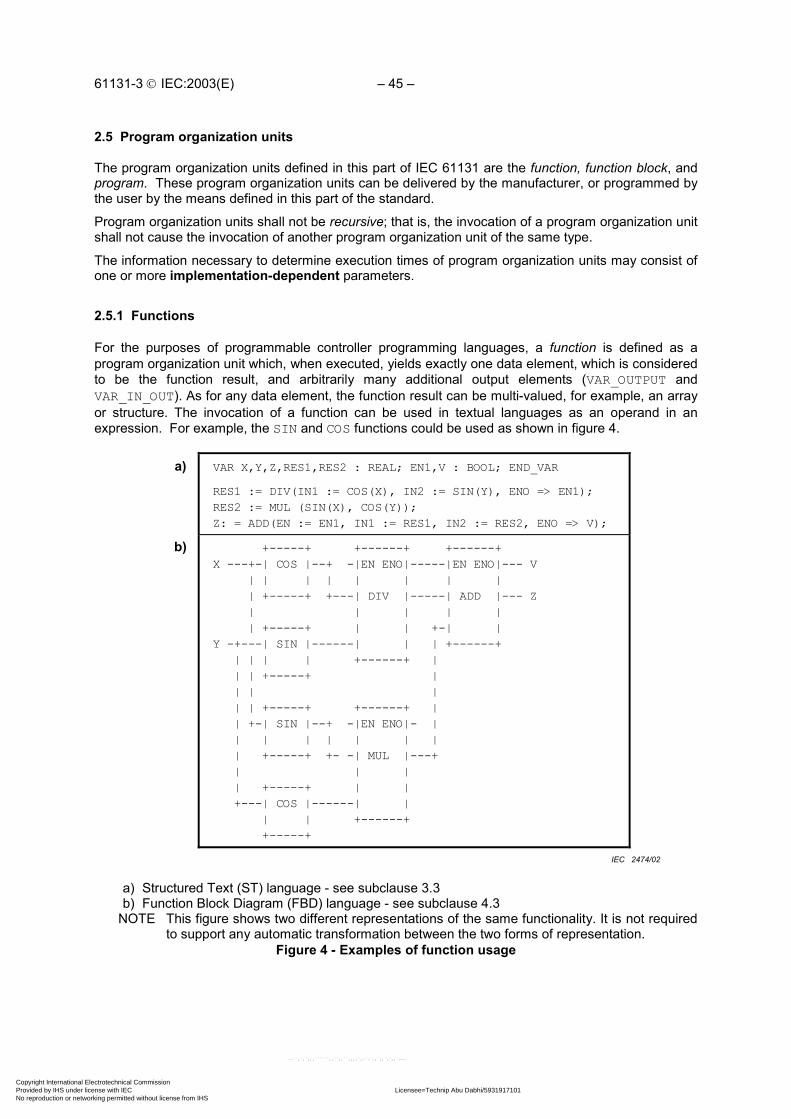
61131-3 IEC:2003(E) – 45 –
2.5 Program organization units
The program organization units defined in this part of IEC 61131 are the function, function block, andprogram. These program organization units can be delivered by the manufacturer, or programmed bythe user by the means defined in this part of the standard.
Program organization units shall not be recursive; that is, the invocation of a program organization unitshall not cause the invocation of another program organization unit of the same type.
The information necessary to determine execution times of program organization units may consist ofone or more implementation-dependent parameters.
2.5.1 Functions
For the purposes of programmable controller programming languages, a function is defined as aprogram organization unit which, when executed, yields exactly one data element, which is consideredto be the function result, and arbitrarily many additional output elements (VAR_OUTPUT andVAR_IN_OUT). As for any data element, the function result can be multi-valued, for example, an arrayor structure. The invocation of a function can be used in textual languages as an operand in anexpression. For example, the SIN and COS functions could be used as shown in figure 4.
a) VAR X,Y,Z,RES1,RES2 : REAL; EN1,V : BOOL; END_VAR
RES1 := DIV(IN1 := COS(X), IN2 := SIN(Y), ENO => EN1);RES2 := MUL (SIN(X), COS(Y));Z: = ADD(EN := EN1, IN1 := RES1, IN2 := RES2, ENO => V);
b) +-----+ +------+ +------+X ---+-| COS |--+ -|EN ENO|-----|EN ENO|--- V | | | | | | | | | +-----+ +---| DIV |-----| ADD |--- Z | | | | | | +-----+ | | +-| |Y -+---| SIN |------| | | +------+ | | | | +------+ | | | +-----+ | | | | | | +-----+ +------+ | | +-| SIN |--+ -|EN ENO|- | | | | | | | | | +-----+ +- -| MUL |---+ | | | | +-----+ | | +---| COS |------| | | | +------+ +-----+
a) Structured Text (ST) language - see subclause 3.3b) Function Block Diagram (FBD) language - see subclause 4.3
NOTE This figure shows two different representations of the same functionality. It is not requiredto support any automatic transformation between the two forms of representation.
Figure 4 - Examples of function usage
IEC 2474/02
Copyright International Electrotechnical Commission Provided by IHS under license with IEC Licensee=Technip Abu Dabhi/5931917101
Not for Resale, 02/12/2006 07:01:30 MSTNo reproduction or networking permitted without license from IHS
--``,`,`,,,``````,,``,,``,,,,`,-`-`,,`,,`,`,,`---

– 46 – 61131-3 IEC:2003(E)
Functions shall contain no internal state information, i.e., invocation of a function with the samearguments (input variables VAR_INPUT and in-out variables VAR_IN_OUT) shall always yield thesame values (output variables VAR_OUTPUT, in-out variables VAR_IN_OUT and function result). Itshall be an error if external variables as defined in 2.4.3 cause the violation of this rule.
Any function type which has already been declared can be used in the declaration of another programorganization unit, as shown in figure 3.
2.5.1.1 Representation
Functions and their invocation can be represented either graphically or textually.
In the textual languages defined in clause 3 of this standard, the invocation of functions shall beaccording to the following rules:
1) Input argument assignment shall follow the rules given in table 19 a).
2) Assignments of output variables of the function shall be either empty or to variables.
3) Assignments to VAR_IN_OUT arguments shall be variables.
4) Assignments to VAR_INPUT arguments may be empty (feature 1 of table 19 a)), constants,variables or function calls. In the latter case, the function result is used as the actual argument.
In the graphic languages defined in clause 4 of this standard, functions shall be represented asgraphic blocks according to the following rules:
5) The form of the block shall be rectangular or square.
6) The size and proportions of the block may vary depending on the number of inputs and otherinformation to be displayed.
7) The direction of processing through the block shall be from left to right (input variables on the leftand output variables on the right).
8) The function name or symbol, as specified below, shall be located inside the block.
9) Provision shall be made for input and output variable names appearing at the inside left and rightsides of the block respectively when the block represents:
- one of the standard functions defined in 2.5.1.5, when the given graphical form includes thevariable names; or
- any additional function declared as specified in 2.5.1.3.
This usage is subject to the following provisions:
a) Where no names are given for input variables in standard functions, the default namesIN1, IN2,... shall apply in top-to-bottom order.
b) When a standard function has a single unnamed input, the default name IN shall apply.
c) The default names described above may, but need not appear at the inside left-hand sideof the graphic representation.
Copyright International Electrotechnical Commission Provided by IHS under license with IEC Licensee=Technip Abu Dabhi/5931917101
Not for Resale, 02/12/2006 07:01:30 MSTNo reproduction or networking permitted without license from IHS
--``,`,`,,,``````,,``,,``,,,,`,-`-`,,`,,`,`,,`---

61131-3 IEC:2003(E) – 47 –
10) An additional input EN and/or output ENO as specified in 2.5.1.2 may be used. If present, they shallbe shown at the uppermost positions at the left and right side of the block, respectively.
11) The function result shall be shown at the uppermost position at the right side of the block, except ifthere is an ENO output, in which case the function result shall be shown at the next position belowthe ENO output. Since the name of the function is used for the assignment of its output value asspecified in 2.5.1.3, no output variable name shall be shown at the right side of the block.
12) Argument connections (including function result) shall be shown by signal flow lines.
13) Negation of Boolean signals shall be shown by placing an open circle just outside of the input oroutput line intersection with the block. In the character set defined in 2.1.1, this shall berepresented by the upper case alphabetic “O”, as shown in table 19.
14) All inputs and outputs (including function result) of a graphically represented function shall berepresented by a single line outside the corresponding side of the block, even though the dataelement may be a multi-element variable.
15) Function results and function outputs (VAR_OUTPUT) can be connected to a variable, used asinput to other function blocks or functions, or can be left unconnected.
16) It shall be an error if any VAR_IN_OUT variable of any function block invocation or functioninvocation within a POU is not “properly mapped”. A VAR_IN_OUT variable is “properly mapped” ifit is connected graphically at the left, or assigned using the “:=” operator in a textual invocation, toa variable declared (without the CONSTANT qualifier) in a VAR_IN_OUT, VAR, VAR_OUT, orVAR_EXTERNAL block of the containing program organization unit, or to a “properly mapped”VAR_IN_OUT of another contained function block instance or function invocation.
17) A “properly mapped” (see rule 12 above) VAR_IN_OUT variable of a function block instance or afunction invocation can be connected graphically at the right, or assigned using the “:=” operator ina textual assignment statement, to a variable declared in a VAR, VAR_OUT or VAR_EXTERNALblock of the containing program organization unit. It shall be an error if such a connection wouldlead to an ambiguous value of the variable so connected.
Table 19 - Graphical negation of Boolean signals
No. Featurea, b Representation
1 Negated input +---+ ---O| |--- +---+
2 Negated output +---+ ----| |O--- +---+
a If either of these features is supported for functions, it shall alsobe supported for function blocks as defined in 2.5.2, and viceversa.
b The use of these constructs is forbidden for in-out variables.
Copyright International Electrotechnical Commission Provided by IHS under license with IEC Licensee=Technip Abu Dabhi/5931917101
Not for Resale, 02/12/2006 07:01:30 MSTNo reproduction or networking permitted without license from IHS
--``,`,`,,,``````,,``,,``,,,,`,-`-`,,`,,`,`,,`---

– 48 – 61131-3 IEC:2003(E)
Figure 5 illustrates both the graphical and equivalent textual use of functions, including the use of astandard function (ADD) with no defined formal argument names; a standard function (SHL) withdefined formal argument names; the same function with additional use of EN input and negated ENOoutput; and a user-defined function (INC) with defined formal argument names.
Example Explanation
+-----+ | ADD | B---| |---AC---| |D---| | +-----+
Graphical use of ADD function(See 2.5.1.5.2)
(FBD language; see 4.3)(No formal variable names)
A := ADD(B,C,D); Textual use of ADD function(ST language; see 3.3)
+-----+ | SHL | B---|IN |---AC---|N | +-----+
Graphical use of SHL function(See 2.5.1.5.3)
(FBD language; see 4.3)(Formal argument names)
A := SHL(IN := B,N := C); Textual use of SHL function(ST language; see 3.3)
+---------+ | SHL | ENABLE---|EN ENO|O--NO_ERR
B---|IN |---AC---|N | +---------+
Graphical use of SHL function(See 2.5.1.5.3)
(FBD language; see 4.3)(Formal argument names; use of EN input
and negated ENO output)
A := SHL(EN:=ENABLE, IN:=B, N:=C,NOT ENO => NO_ERR);
Textual use of SHL function(ST language; see 3.3)
+-----+ | INC | | |---A X---|V---V|---X +-----+
Graphical use of user-definedINC function
(FBD language, see 4.3)
(Formal argument names for VAR_IN_OUT)
A := INC(V := X) ; Textual use of INC function(ST language, see 3.3)
Figure 5 - Use of formal argument names
Features for the textual invocation of functions are defined in table 19 a). The textual invocation of afunction shall consist of the function name followed by a list of arguments. In the ST language definedin subclause 3.3, the arguments shall be separated by commas and this list shall be delimited on theleft and right by parentheses.
In feature 1 of table 19 a) (formal invocation), the argument list has the form of a set of assignments ofactual values to the formal argument names (formal argument list), that is:
1) assignments of values to input and in-out variables using the ":=" operator, and2) assignments of the values of output variables to variables using the "=>" operator.
IEC 2475/02
Copyright International Electrotechnical Commission Provided by IHS under license with IEC Licensee=Technip Abu Dabhi/5931917101
Not for Resale, 02/12/2006 07:01:30 MSTNo reproduction or networking permitted without license from IHS
--``,`,`,,,``````,,``,,``,,,,`,-`-`,,`,,`,`,,`---

61131-3 IEC:2003(E) – 49 –
The ordering of arguments in the list shall be insignificant. In feature 1 of table 19 a), any variable notassigned a value in the list shall have the default value, if any, assigned in the function specification,or the default value for the associated data type.
In feature 2 of table 19 a) (non-formal invocation), the argument list shall contain exactly the samenumber of arguments, in exactly the same order and of the same data types as given in the functiondefinition, except the execution control arguments EN and ENO.
Table 19 a) - Textual invocation of functions for formal and non-formal argument list
Feature ExampleNo. Invocation
typeVariable
assignment
Variableorder
Number ofvariables
In Structured Text (ST) language- see 3.3
1 formal yes any any A := LIMIT(EN:=COND, IN:=B, MX:=5, ENO=>TEMPL);
2 a non-formal no fixed fixed A := LIMIT(1, B, 5);a Feature #2 is required for invocation of any of the standard functions defined in subclause
2.5.1.5 without formal names for one or more input variables, but feature #1 shall be used ifEN/ENO is necessary in function invocations.
NOTE 1 In the example given in feature #1, the MN variable will have the default value 0(zero).
NOTE 2 The example given in feature #2 is semantically equivalent to the followinginvocation with formal variable assignments (feature #1):
A := LIMIT(EN := TRUE,MN := 1, IN := B, MX := 5);
2.5.1.2 Execution control
As shown in table 20, an additional Boolean EN (Enable) input or ENO (Enable Out) output, or both,can be provided by the manufacturer or user according to the declarations
VAR_INPUT EN: BOOL := 1; END_VARVAR_OUTPUT ENO: BOOL; END_VAR
When these variables are used, the execution of the operations defined by the function shall becontrolled according to the following rules:
1) If the value of EN is FALSE (0) when the function is invoked, the operations defined by thefunction body shall not be executed and the value of ENO shall be reset to FALSE (0) by theprogrammable controller system.
2) Otherwise, the value of ENO shall be set to TRUE (1) by the programmable controller system,and the operations defined by the function body shall be executed. These operations caninclude the assignment of a Boolean value to ENO.
3) If any of the errors defined in table E.1 for subclauses of 2.5.1.5 occurs during the execution ofone of the standard functions defined in 2.5.1.5, the ENO output of that function shall be reset toFALSE (0) by the programmable controller system, or the manufacturer shall specify otherdisposition of such an error according to the provisions of 1.5.1.
4) If the ENO output is evaluated to FALSE (0), the values of all function outputs (VAR_OUTPUT,VAR_IN_OUT and function result) shall be considered to be implementation-dependent.
Copyright International Electrotechnical Commission Provided by IHS under license with IEC Licensee=Technip Abu Dabhi/5931917101
Not for Resale, 02/12/2006 07:01:30 MSTNo reproduction or networking permitted without license from IHS
--``,`,`,,,``````,,``,,``,,,,`,-`-`,,`,,`,`,,`---
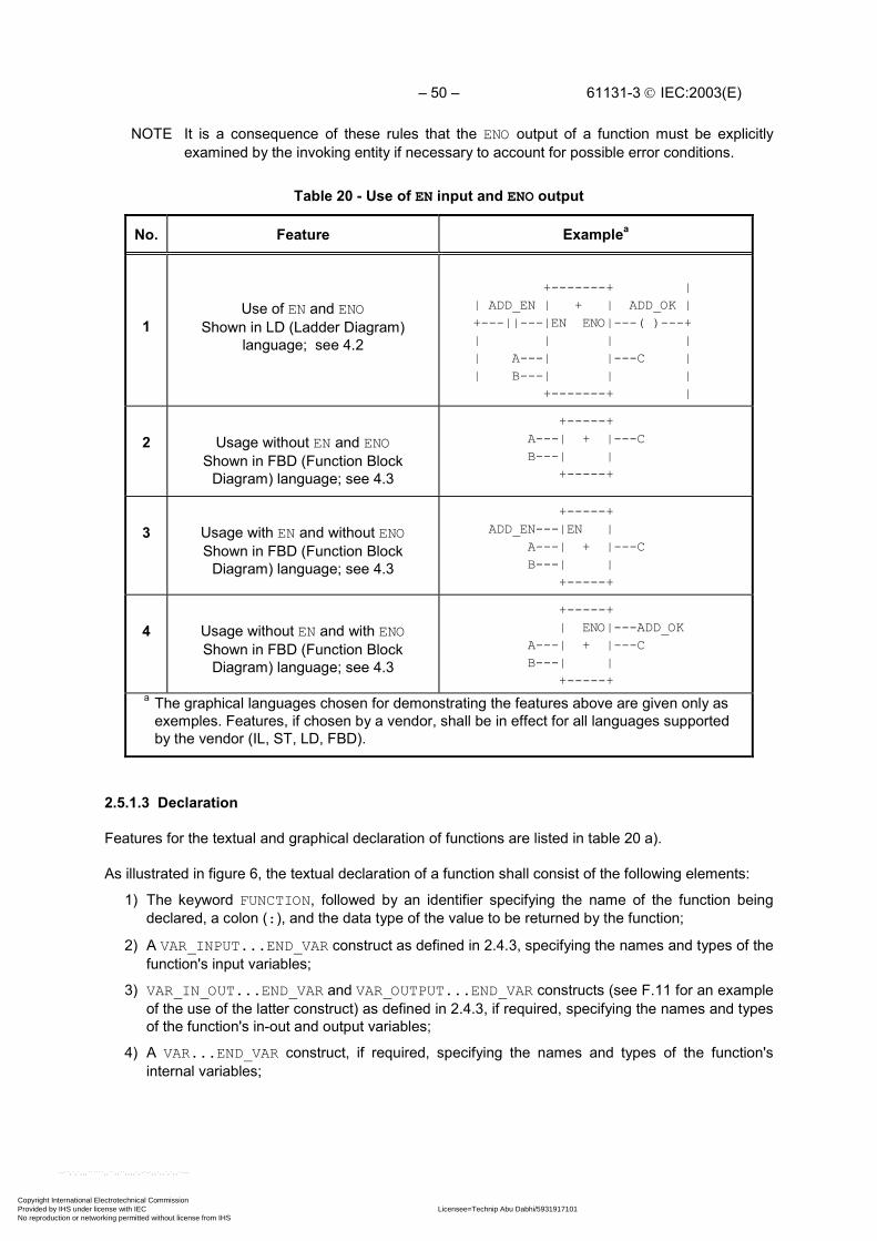
– 50 – 61131-3 IEC:2003(E)
NOTE It is a consequence of these rules that the ENO output of a function must be explicitlyexamined by the invoking entity if necessary to account for possible error conditions.
Table 20 - Use of EN input and ENO output
No. Feature Examplea
1Use of EN and ENO
Shown in LD (Ladder Diagram)language; see 4.2
+-------+ | | ADD_EN | + | ADD_OK | +---||---|EN ENO|---( )---+ | | | | | A---| |---C | | B---| | | +-------+ |
2 Usage without EN and ENOShown in FBD (Function Block
Diagram) language; see 4.3
+-----+ A---| + |---C B---| | +-----+
3 Usage with EN and without ENOShown in FBD (Function Block
Diagram) language; see 4.3
+-----+ ADD_EN---|EN | A---| + |---C B---| | +-----+
4 Usage without EN and with ENOShown in FBD (Function Block
Diagram) language; see 4.3
+-----+ | ENO|---ADD_OK A---| + |---C B---| | +-----+
a The graphical languages chosen for demonstrating the features above are given only asexemples. Features, if chosen by a vendor, shall be in effect for all languages supportedby the vendor (IL, ST, LD, FBD).
2.5.1.3 Declaration
Features for the textual and graphical declaration of functions are listed in table 20 a).
As illustrated in figure 6, the textual declaration of a function shall consist of the following elements:
1) The keyword FUNCTION, followed by an identifier specifying the name of the function beingdeclared, a colon (:), and the data type of the value to be returned by the function;
2) A VAR_INPUT...END_VAR construct as defined in 2.4.3, specifying the names and types of thefunction's input variables;
3) VAR_IN_OUT...END_VAR and VAR_OUTPUT...END_VAR constructs (see F.11 for an exampleof the use of the latter construct) as defined in 2.4.3, if required, specifying the names and typesof the function's in-out and output variables;
4) A VAR...END_VAR construct, if required, specifying the names and types of the function'sinternal variables;
Copyright International Electrotechnical Commission Provided by IHS under license with IEC Licensee=Technip Abu Dabhi/5931917101
Not for Resale, 02/12/2006 07:01:30 MSTNo reproduction or networking permitted without license from IHS
--``,`,`,,,``````,,``,,``,,,,`,-`-`,,`,,`,`,,`---

61131-3 IEC:2003(E) – 51 –
5) A function body, written in one of the languages defined in this standard, or anotherprogramming language as defined in 1.4.3, which specifies the operations to be performed uponthe variable(s) in order to assign values dependent on the function's semantics to a variablewith the same name as the function, which represents the function result to be returned by thefunction (function result), as well as to in-out or output variables;
6) The terminating keyword END_FUNCTION.
If the generic data types given in table 11 are used in the declaration of standard function variables,then the rules for inferring the actual types of the arguments of such functions shall be part of thefunction definition.
The variable initialization constructs defined in 2.4.3.2 can be used for the declaration of default valuesof function inputs and initial values of their internal and output variables.
The values of variables which are passed to the function via a VAR_IN_OUT construct can be modifiedfrom within the function.
As illustrated in figure 6, the graphic declaration of a function shall consist of the following elements:
1) The bracketing keywords FUNCTION...END_FUNCTION or a graphical equivalent.
2) A graphic specification of the function name and the names, types and possibly initial values ofthe function's result and variables (input, output and in-out).
3) A specification of the names, types and possibly initial values of the internal variables used inthe function, for example, using the VAR...END_VAR construct.
4) A function body as defined above.
The maximum number of function specifications allowed in a particular resource is animplementation-dependent parameter.
Table 20 a) - Function features
No. Description Example
1 In-out variable declaration (textual) VAR_IN_OUT A: INT; END_VAR
2 In-out variable declaration (graphical) See figure 6 b)
3 Graphical connection of in-out variable to differentvariables(graphical)
See figure 6 d)
Copyright International Electrotechnical Commission Provided by IHS under license with IEC Licensee=Technip Abu Dabhi/5931917101
Not for Resale, 02/12/2006 07:01:30 MSTNo reproduction or networking permitted without license from IHS
--``,`,`,,,``````,,``,,``,,,,`,-`-`,,`,,`,`,,`---

– 52 – 61131-3 IEC:2003(E)
a) FUNCTION SIMPLE_FUN : REAL VAR_INPUT A,B : REAL ; (* External interface specification *) C : REAL := 1.0; END_VAR VAR_IN_OUT COUNT : INT ; END_VAR VAR COUNTP1 : INT ; END_VAR
COUNTP1 := ADD(COUNT,1); (*Function body specification *) COUNT := COUNTP1 ; SIMPLE_FUN := A*B/C; END_FUNCTION
NOTE In the above example, the input variable is given a default value of 1.0, asspecified in 2.4.3.2, to avoid a “division by zero” error if the input is not specifiedwhen the function is invoked, for example, if a graphical input to the function isleft unconnected.
b) FUNCTION +-------------+ (* External interface specification *) | SIMPLE_FUN | REAL----|A |----REAL REAL----|B | REAL----|C | INT-----|COUNT---COUNT|----INT +-------------+(* Function body specification *) +---+ |ADD|--- +----+ COUNT--| |---COUNTP1--| := |---COUNT 1--| | +----+ +---+ +---+ A---| * | +---+ B---| |---| / |---SIMPLE_FUN +---+ | | C-----------| | +---+ END_FUNCTION
c) ....VAR X,Y,Z,RESULT : REAL:VAR COUNT1,COUNT2 : INT; ...RESULT := SIMPLE_FUN(A:=X,B:=Y,C:=Z,COUNT:=COUNT1);COUNT2 := COUNT1; ...
d) +-------------+ | SIMPLE_FUN | X----|A |----RESULT Y----|B | Z----|C | COUNT1---|COUNT---COUNT|----COUNT2 +-------------+
NOTE The effect of this invocation of this function is identical to thatin figure 6 c)
a) Textual declaration in ST language (subclause 3.3)b) Graphical declaration in FBD language (subclause 4.3)c) Usage of a function in ST languaged) Usage of a function in FBD language (subclause 4.3)
Figure 6 - Examples of function declarations and usage IEC 2476/02
Copyright International Electrotechnical Commission Provided by IHS under license with IEC Licensee=Technip Abu Dabhi/5931917101
Not for Resale, 02/12/2006 07:01:30 MSTNo reproduction or networking permitted without license from IHS
--``,`,`,,,``````,,``,,``,,,,`,-`-`,,`,,`,`,,`---

61131-3 IEC:2003(E) – 53 –
2.5.1.4 Typing, overloading, and type conversion
A standard function, function block type, operator, or instruction is said to be overloaded when it canoperate on input data elements of various types within a generic type designator as defined in 2.3.2.For instance, an overloaded addition function on generic type ANY_NUM can operate on data of typesLREAL, REAL, DINT, INT, and SINT.
When a programmable controller system supports an overloaded standard function, function blocktype, operator, or instruction, this standard function, function block type, operator, or instruction shallapply to all data types of the given generic type which are supported by that system. For example, if aprogrammable controller system supports the overloaded function ADD and the data types SINT, INT,and REAL, then the system shall support the ADD function on inputs of type SINT, INT, and REAL.
When a function which normally represents an overloaded operator is to be typed, i.e., the types of itsinputs and outputs restricted to a particular elementary or derived data type as defined in 2.3, this shallbe done by appending an “underline” character followed by the required type, as shown in table 21.
Table 21 - Typed and overloaded functions
No. Feature Example
1 Overloaded functions
+-----+ | ADD | ANY_NUM-----| |----ANY_NUM ANY_NUM-----| | . -----| | . -----| | ANY_NUM-----| | +-----+
2 a Typed functions
+---------+ | ADD_INT | INT-----| |----INT INT-----| | . -----| | . -----| | INT-----| | +---------+
NOTE The overloading of non-standard functions or function block types is beyond the scope ofthis standard.
a If feature 2 is supported, the manufacturer shall provide a table of which functions areoverloaded and which are typed in the implementation.
When the type of the result of a standard function defined in 2.5.1.5 is generic, then the actual types ofall input variables of the same generic type shall be of the same type as the actual type of the functionvalue in a given invocation of the function. If necessary, the type conversion functions defined in2.5.1.5.1 can be used to meet this requirement. Examples of the application of this rule are given infigures 7 and 8.
Copyright International Electrotechnical Commission Provided by IHS under license with IEC Licensee=Technip Abu Dabhi/5931917101
Not for Resale, 02/12/2006 07:01:30 MSTNo reproduction or networking permitted without license from IHS
--``,`,`,,,``````,,``,,``,,,,`,-`-`,,`,,`,`,,`---
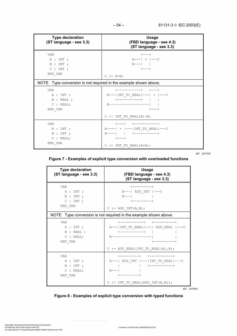
– 54 – 61131-3 IEC:2003(E)
Type declaration(ST language - see 3.3)
Usage(FBD language - see 4.3)(ST language - see 3.3)
VAR A : INT ; B : INT ; C : INT ; END_VAR
+---+ A---| + |---C B---| | +---+
C := A+B;
NOTE Type conversion is not required in the example shown above.
VAR A : INT ; B : REAL ; C : REAL; END_VAR
+-----------+ +---+ A---|INT_TO_REAL|---| + |---C +-----------+ | | B-------------------| | +---+
C := INT_TO_REAL(A)+B;
VAR A : INT ; B : INT ; C : REAL; END_VAR
+---+ +-----------+A----| + |---|INT_TO_REAL|---CB----| | +-----------+ +---+
C := INT_TO_REAL(A+B);
Figure 7 - Examples of explicit type conversion with overloaded functions
Type declaration(ST language - see 3.3)
Usage(FBD language - see 4.3)(ST language - see 3.3)
VAR A : INT ; B : INT ; C : INT ; END_VAR
+---------+ A---| ADD_INT |---C B---| | +---------+
C := ADD_INT(A,B);
NOTE Type conversion is not required in the example shown above.
VAR A : INT ; B : REAL ; C : REAL; END_VAR
+-----------+ +----------+ A---|INT_TO_REAL|---| ADD_REAL |---C +-----------+ | | B-------------------| | +----------+
C := ADD_REAL(INT_TO_REAL(A),B);
VAR A : INT ; B : INT ; C : REAL; END_VAR
+---------+ +-----------+ A---| ADD_INT |---|INT_TO_REAL|---C | | +-----------+ B---| | +---------+
C := INT_TO_REAL(ADD_INT(A,B));
Figure 8 - Examples of explicit type conversion with typed functions
IEC 2477/02
IEC 2478/02
Copyright International Electrotechnical Commission Provided by IHS under license with IEC Licensee=Technip Abu Dabhi/5931917101
Not for Resale, 02/12/2006 07:01:30 MSTNo reproduction or networking permitted without license from IHS
--``,`,`,,,``````,,``,,``,,,,`,-`-`,,`,,`,`,,`---

61131-3 IEC:2003(E) – 55 –
2.5.1.5 Standard functions
Definitions of functions common to all programmable controller programming languages are given inthis subclause. Where graphical representations of standard functions are shown in this subclause,equivalent textual declarations may be written as specified in 2.5.1.3.
A standard function specified in this subclause to be extensible is allowed to have two or more inputsto which the indicated operation is to be applied, for example, extensible addition shall give as itsoutput the sum of all its inputs. The maximum number of inputs of an extensible function is animplementation-dependent parameter. The actual number of inputs effective in a formal call of anextensible function is determined by the formal input name with the highest position in the sequence ofparameter names.
EXAMPLE 1 The statement X := ADD(Y1,Y2,Y3);is equivalent to X := ADD(IN1 := Y1, IN2 := Y2, IN3 := Y3);
EXAMPLE 2 The following statements are equivalent: I := MUX_INT(K:=3,IN0 := 1, IN2 := 2, IN4 := 3);I := 0;
2.5.1.5.1 Type conversion functions
As shown in table 22, type conversion functions shall have the form *_TO_**, where “*” is the type ofthe input variable IN, and “**” the type of the output variable OUT, for example, INT_TO_REAL. Theeffects of type conversions on accuracy, and the types of errors that may arise during execution oftype conversion operations, are implementation-dependent parameters.
Table 22 - Type conversion function features
No. Graphical form Usage example
1a,b,e +---------+ * ---| *_TO_** |--- ** +---------+
(*) - Input data type, e.g., INT (**) - Output data type, e.g., REAL (*_TO_**) - Function name, e.g., INT_TO_REAL
A := INT_TO_REAL(B) ;
2c +-------+ ANY_REAL---| TRUNC |---ANY_INT +-------+
A := TRUNC(B) ;
3d +-------------+ *--| *_BCD_TO_** |---** +-------------+
A := WORD_BCD_TO_INT(B);
4d +-------------+ **--| **_TO_BCD_* |---* +-------------+
A := INT_TO_BCD_WORD(B);
NOTE Usage examples are given in the ST language defined in 3.3.
Copyright International Electrotechnical Commission Provided by IHS under license with IEC Licensee=Technip Abu Dabhi/5931917101
Not for Resale, 02/12/2006 07:01:30 MSTNo reproduction or networking permitted without license from IHS
--``,`,`,,,``````,,``,,``,,,,`,-`-`,,`,,`,`,,`---

– 56 – 61131-3 IEC:2003(E)
Table 22 - Type conversion function featuresa A statement of conformance to feature 1 of this table shall include a list of the specific type
conversions supported, and a statement of the effects of performing each conversion.b Conversion from type REAL or LREAL to SINT, INT, DINT or LINT shall round according to
the convention of IEC 60559, according to which, if the two nearest integers are equallynear, the result shall be the nearest even integer, e.g.:
REAL_TO_INT(1.6) is equivalent to 2REAL_TO_INT(-1.6) is equivalent to -2
REAL_TO_INT(1.5) is equivalent to 2REAL_TO_INT(-1.5) is equivalent to -2
REAL_TO_INT(1.4) is equivalent to 1REAL_TO_INT(-1.4) is equivalent to -1
REAL_TO_INT(2.5) is equivalent to 2REAL_TO_INT(-2.5) is equivalent to –2c The function TRUNC shall be used for truncation toward zero of a REAL or LREAL, yielding
one of the integer types, for instance,
TRUNC(1.6) is equivalent to 1TRUNC(-1.6) is equivalent to -1
TRUNC(1.4) is equivalent to 1TRUNC(-1.4) is equivalent to -1d The conversion functions *_BCD_TO_** and **_TO_BCD_* shall perform conversions
between variables of type BYTE, WORD, DWORD, and LWORD and variables of typeUSINT, UINT, UDINT and ULINT (represented by "*" and "**" respectively), when thecorresponding bit-string variables contain data encoded in BCD format. For example, thevalue of USINT_TO_BCD_BYTE(25) would be 2#0010_0101, and the value ofWORD_BCD_TO_UINT (2#0011_0110_1001) would be 369.
e When an input or output of a type conversion function is of type STRING orWSTRING, the character string data shall conform to the external representationof the corresponding data, as specified in 2.2, in the character set defined in2.1.1.
2.5.1.5.2 Numerical functions
The standard graphical representation, function names, input and output variable types, and functiondescriptions of functions of a single numeric variable shall be as defined in table 23. These functionsshall be overloaded on the defined generic types, and can be typed as defined in 2.5.1.4. For thesefunctions, the types of the input and output shall be the same.
The standard graphical representation, function names and symbols, and descriptions of arithmeticfunctions of two or more variables shall be as shown in table 24. These functions shall be overloadedon all numeric types, and can be typed as defined in 2.5.1.4.
The accuracy of numerical functions shall be expressed in terms of one or more implementation-dependent parameters.
It is an error if the result of evaluation of one of these functions exceeds the range of values specifiedfor the data type of the function output, or if division by zero is attempted.
Copyright International Electrotechnical Commission Provided by IHS under license with IEC Licensee=Technip Abu Dabhi/5931917101
Not for Resale, 02/12/2006 07:01:30 MSTNo reproduction or networking permitted without license from IHS
--``,`,`,,,``````,,``,,``,,,,`,-`-`,,`,,`,`,,`---

61131-3 IEC:2003(E) – 57 –
Table 23 - Standard functions of one numeric variable
Graphical form Usage example
+---------+* ---| ** |--- * +---------+(*) - Input/Output (I/O) type(**) - Function name
A := SIN(B) ;
(ST language - see 3.3)
No. Function name I/O type Description
General functions
1 ABS ANY_NUM Absolute value
2 SQRT ANY_REAL Square root
Logarithmic functions
3 LN ANY_REAL Natural logarithm
4 LOG ANY_REAL Logarithm base 10
5 EXP ANY_REAL Natural exponential
Trigonometric functions
6 SIN ANY_REAL Sine of input in radians
7 COS ANY_REAL Cosine in radians
8 TAN ANY_REAL Tangent in radians
9 ASIN ANY_REAL Principal arc sine
10 ACOS ANY_REAL Principal arc cosine
11 ATAN ANY_REAL Principal arc tangent
Copyright International Electrotechnical Commission Provided by IHS under license with IEC Licensee=Technip Abu Dabhi/5931917101
Not for Resale, 02/12/2006 07:01:30 MSTNo reproduction or networking permitted without license from IHS
--``,`,`,,,``````,,``,,``,,,,`,-`-`,,`,,`,`,,`---
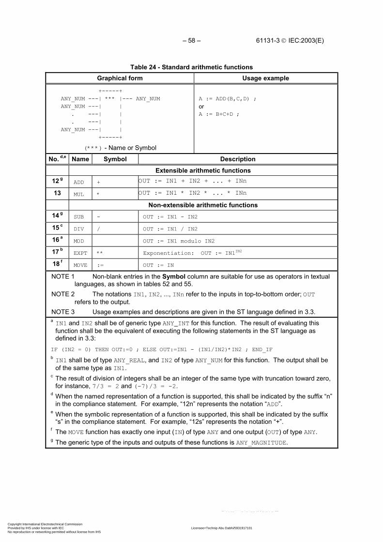
– 58 – 61131-3 IEC:2003(E)
Table 24 - Standard arithmetic functionsGraphical form Usage example
+-----+ ANY_NUM ---| *** |--- ANY_NUM ANY_NUM ---| | . ---| | . ---| | ANY_NUM ---| | +-----+
(***) - Name or Symbol
A := ADD(B,C,D) ;orA := B+C+D ;
No. d,e Name Symbol Description
Extensible arithmetic functions12 g
ADD + OUT := IN1 + IN2 + ... + INn
13 MUL * OUT := IN1 * IN2 * ... * INn
Non-extensible arithmetic functions14 g
SUB - OUT := IN1 - IN2
15 cDIV / OUT := IN1 / IN2
16 aMOD OUT := IN1 modulo IN2
17 bEXPT ** Exponentiation: OUT := IN1IN2
18 fMOVE := OUT := IN
NOTE 1 Non-blank entries in the Symbol column are suitable for use as operators in textuallanguages, as shown in tables 52 and 55.
NOTE 2 The notations IN1, IN2, ..., INn refer to the inputs in top-to-bottom order; OUTrefers to the output.
NOTE 3 Usage examples and descriptions are given in the ST language defined in 3.3.a IN1 and IN2 shall be of generic type ANY_INT for this function. The result of evaluating this
function shall be the equivalent of executing the following statements in the ST language asdefined in 3.3:
IF (IN2 = 0) THEN OUT:=0 ; ELSE OUT:=IN1 - (IN1/IN2)*IN2 ; END_IFb IN1 shall be of type ANY_REAL, and IN2 of type ANY_NUM for this function. The output shall be
of the same type as IN1.c The result of division of integers shall be an integer of the same type with truncation toward zero,
for instance, 7/3 = 2 and (-7)/3 = -2.d When the named representation of a function is supported, this shall be indicated by the suffix “n”
in the compliance statement. For example, “12n” represents the notation “ADD”.e When the symbolic representation of a function is supported, this shall be indicated by the suffix
“s” in the compliance statement. For example, “12s” represents the notation “+”.f The MOVE function has exactly one input (IN) of type ANY and one output (OUT) of type ANY.g The generic type of the inputs and outputs of these functions is ANY_MAGNITUDE.
Copyright International Electrotechnical Commission Provided by IHS under license with IEC Licensee=Technip Abu Dabhi/5931917101
Not for Resale, 02/12/2006 07:01:30 MSTNo reproduction or networking permitted without license from IHS
--``,`,`,,,``````,,``,,``,,,,`,-`-`,,`,,`,`,,`---

61131-3 IEC:2003(E) – 59 –
2.5.1.5.3 Bit string functions
The standard graphical representation, function names and descriptions of shift functions for a singlebit-string variable shall be as defined in table 25. These functions shall be overloaded on all bit-stringtypes, and can be typed as defined in 2.5.1.4.
The standard graphical representation, function names and symbols, and descriptions of bitwiseBoolean functions shall be as defined in table 26. These functions shall be extensible, except for NOT,and overloaded on all bit-string types, and can be typed as defined in 2.5.1.4.
Table 25 - Standard bit shift functions
Graphical form Usage example a
+-----+ | *** | ANY_BIT ---|IN |--- ANY_BIT ANY_INT ---|N | +-----+
(***) - Function Name
A := SHL(IN:=B, N:=5) ;
(ST language - see 3.3)
No. Name Description
1 SHL OUT := IN left-shifted by N bits, zero-filled on right
2 SHR OUT := IN right-shifted by N bits, zero-filled on left
3 ROR OUT := IN right-rotated by N bits, circular
4 ROL OUT := IN left-rotated by N bits, circularNOTE The notation OUT refers to the function output.a It shall be an error if the value of the N input is less than zero.
2.5.1.5.4 Selection and comparison functions
Selection and comparison functions shall be overloaded on all data types. The standard graphicalrepresentations, function names and descriptions of selection functions shall be as shown in table 27.
The standard graphical representation, function names and symbols, and descriptions of comparisonfunctions shall be as defined in table 28. All comparison functions (except NE) shall be extensible.
Comparisons of bit string data shall be made bitwise from the most significant to the least significantbit, and shorter bit strings shall be considered to be filled on the left with zeros when compared tolonger bit strings; that is, comparison of bit string variables shall have the same result as comparisonof unsigned integer variables.
Copyright International Electrotechnical Commission Provided by IHS under license with IEC Licensee=Technip Abu Dabhi/5931917101
Not for Resale, 02/12/2006 07:01:30 MSTNo reproduction or networking permitted without license from IHS
--``,`,`,,,``````,,``,,``,,,,`,-`-`,,`,,`,`,,`---

– 60 – 61131-3 IEC:2003(E)
Table 26 - Standard bitwise Boolean functions
Graphical form Usage examples
+-----+ ANY_BIT ---| *** |--- ANY_BIT ANY_BIT ---| | : ---| | : ---| | ANY_BIT ---| | +-----+
(***) - Name or symbol
A := AND(B,C,D) ;
or
A := B & C & D ;
No. a,b Name Symbol Description
5 AND & (NOTE 1) OUT := IN1 & IN2 & ... & INn
6 OR >=1 (NOTE 2) OUT := IN1 OR IN2 OR ... OR INn
7 XOR =2k+1 (NOTE 2) OUT := IN1 XOR IN2 XOR ... XOR INn
8 NOT OUT := NOT IN1 (NOTE 4)
NOTE 1 This symbol is suitable for use as an operator in textual languages, as shown in tables52 and 55.
NOTE 2 This symbol is not suitable for use as an operator in textual languages.
NOTE 3 The notations IN1, IN2, ..., INn refer to the inputs in top-to-bottom order; OUT refers tothe output.
NOTE 4 Graphic negation of signals of type BOOL can also be accomplished as shown in table19.
NOTE 5 Usage examples and descriptions are given in the ST language defined in 3.3.a When the named representation of a function is supported, this shall be indicated by the suffix
“n” in the compliance statement. For example, “5n” represents the notation “AND”.b When the symbolic representation of a function is supported, this shall be indicated by the suffix
“s” in the compliance statement. For example, “5s” represents the notation “&”.
Copyright International Electrotechnical Commission Provided by IHS under license with IEC Licensee=Technip Abu Dabhi/5931917101
Not for Resale, 02/12/2006 07:01:30 MSTNo reproduction or networking permitted without license from IHS
--``,`,`,,,``````,,``,,``,,,,`,-`-`,,`,,`,`,,`---
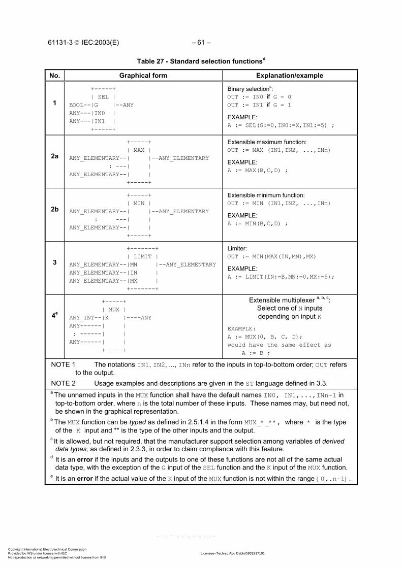
61131-3 IEC:2003(E) – 61 –
Table 27 - Standard selection functionsd
No. Graphical form Explanation/example
1
+-----+ | SEL |BOOL--|G |--ANYANY---|IN0 |ANY---|IN1 | +-----+
Binary selectionc:OUT := IN0 if G = 0OUT := IN1 if G = 1
EXAMPLE:A := SEL(G:=0,IN0:=X,IN1:=5) ;
2a
+-----+ | MAX |ANY_ELEMENTARY--| |--ANY_ELEMENTARY : ---| |ANY_ELEMENTARY--| | +-----+
Extensible maximum function:OUT := MAX (IN1,IN2, ...,INn)
EXAMPLE:A := MAX(B,C,D) ;
2b
+-----+ | MIN |ANY_ELEMENTARY--| |--ANY_ELEMENTARY : ---| |ANY_ELEMENTARY--| | +-----+
Extensible minimum function:OUT := MIN (IN1,IN2, ...,INn)
EXAMPLE:A := MIN(B,C,D) ;
3
+-------+ | LIMIT |ANY_ELEMENTARY--|MN |--ANY_ELEMENTARYANY_ELEMENTARY--|IN |ANY_ELEMENTARY--|MX | +-------+
Limiter:OUT := MIN(MAX(IN,MN),MX)
EXAMPLE:A := LIMIT(IN:=B,MN:=0,MX:=5);
4e
+-----+ | MUX |ANY_INT--|K |----ANYANY------| | : ------| |ANY------| | +-----+
Extensible multiplexer a, b, c:Select one of N inputsdepending on input K
EXAMPLE:A := MUX(0, B, C, D);would have the same effect as A := B ;
NOTE 1 The notations IN1, IN2, ..., INn refer to the inputs in top-to-bottom order; OUT refersto the output.
NOTE 2 Usage examples and descriptions are given in the ST language defined in 3.3.a The unnamed inputs in the MUX function shall have the default names IN0, IN1,...,INn-1 in
top-to-bottom order, where n is the total number of these inputs. These names may, but need not,be shown in the graphical representation.
b The MUX function can be typed as defined in 2.5.1.4 in the form MUX_*_**, where * is the typeof the K input and ** is the type of the other inputs and the output.
c It is allowed, but not required, that the manufacturer support selection among variables of deriveddata types, as defined in 2.3.3, in order to claim compliance with this feature.
d It is an error if the inputs and the outputs to one of these functions are not all of the same actualdata type, with the exception of the G input of the SEL function and the K input of the MUX function.
e It is an error if the actual value of the K input of the MUX function is not within the range {0..n-1}.
Copyright International Electrotechnical Commission Provided by IHS under license with IEC Licensee=Technip Abu Dabhi/5931917101
Not for Resale, 02/12/2006 07:01:30 MSTNo reproduction or networking permitted without license from IHS
--``,`,`,,,``````,,``,,``,,,,`,-`-`,,`,,`,`,,`---

– 62 – 61131-3 IEC:2003(E)
Table 28 - Standard comparison functions
Graphical form Usage examples
+-----+ANY_ELEMENTARY --| *** |--- BOOL : --| |ANY_ELEMENTARY --| | +-----+
(***) - Name or Symbol
A := GT(B,C,D) ;
or
A := (B>C) & (C>D) ;
No. Name a Symbol b Description
5 GT > Decreasing sequence:OUT := (IN1>IN2) & (IN2>IN3) & ... & (INn-1 > INn)
6 GE >= Monotonic sequence:OUT := (IN1>=IN2)&(IN2>=IN3)& ... & (INn-1 >= INn)
7 EQ = Equality:OUT := (IN1=IN2) & (IN2=IN3) & ... & (INn-1 = INn)
8 LE <= Monotonic sequence:OUT := (IN1<=IN2)&(IN2<=IN3)& ... & (INn-1 <= INn)
9 LT < Increasing sequence:OUT := (IN1<IN2) & (IN2<IN3) & ... & (INn-1 < INn)
10 NE <> Inequality (non-extensible) OUT := (IN1 <> IN2)
NOTE 1 The notations IN1, IN2, ..., INn refer to the inputs in top-to-bottom order; OUTrefers to the output.
NOTE 2 All the symbols shown in this table are suitable for use as operators in textuallanguages, as shown in tables 52 and 55.
NOTE 3 Usage examples and descriptions are given in the ST language defined in 3.3.a When the named representation of a function is supported, this shall be indicated by the suffix “n”
in the compliance statement. For example, “5n” represents the notation “GT”.b When the symbolic representation of a function is supported, this shall be indicated by the suffix
“s” in the compliance statement. For example, “5s” represents the notation “>“.
2.5.1.5.5 Character string functions
All the functions defined in 2.5.1.5.4 shall be applicable to character strings. For the purposes ofcomparison of two strings of unequal length, the shorter string shall be considered to be extended onthe right to the length of the longer string by characters with the value zero. Comparison shall proceedfrom left to right, based on the numeric value of the character codes in the character set defined in2.1.1. For example, the character string 'Z' shall be greater than the character string 'AZ', and 'AZ'shall be greater than 'ABC'.
The standard graphical representations, function names and descriptions of additional functions ofcharacter strings shall be as shown in table 29. For the purpose of these operations, characterpositions within the string shall be considered to be numbered 1,2,...,L, beginning with theleftmost character position, where L is the length of the string.
Copyright International Electrotechnical Commission Provided by IHS under license with IEC Licensee=Technip Abu Dabhi/5931917101
Not for Resale, 02/12/2006 07:01:30 MSTNo reproduction or networking permitted without license from IHS
--``,`,`,,,``````,,``,,``,,,,`,-`-`,,`,,`,`,,`---

61131-3 IEC:2003(E) – 63 –
It shall be an error if:
- the actual value of any input designated as ANY_INT in table 29 is less than zero;
- evaluation of the function results in an attempt to (1) access a non-existent character position ina string, or (2) produce a string longer than the implementation-dependent maximum stringlength.
Table 29 - Standard character string functions
No. Graphical form a Explanation/example
1 +-----+ ANY_STRING--| LEN |--ANY_INT +-----+
String length functionExample:
A := LEN('ASTRING');is equivalent to A := 7;
2 +------+ | LEFT | ANY_STRING--|IN |--ANY_STRING ANY_INT-----|L | +------+
Leftmost L characters of IN
Example:A := LEFT(IN:='ASTR',L:=3);
is equivalent toA := 'AST' ;
3 +-------+ | RIGHT | ANY_STRING--|IN |--ANY_STRING ANY_INT-----|L | +-------+
Rightmost L characters of IN
Example:A := RIGHT(IN:='ASTR',L:=3);
is equivalent toA := 'STR' ;
4 +-------+ | MID | ANY_STRING--|IN |--ANY_STRING ANY_INT-----|L | ANY_INT-----|P | +-------+
L characters of IN,beginning at the P-th
Example:A := MID(IN:='ASTR',L:=2,P:=2);
is equivalent toA := 'ST' ;
5 +--------+ | CONCAT | ANY_STRING---| |--ANY_STRING : ---| | ANY_STRING---| | +--------+
Extensible concatenation
Example:A := CONCAT('AB','CD','E') ;
is equivalent toA := 'ABCDE' ;
6 +--------+ | INSERT | ANY_STRING--|IN1 |--ANY_STRING ANY_STRING--|IN2 | ANY_INT-----|P | +--------+
Insert IN2 into IN1 after theP-th character position
Example:A:=INSERT(IN1:='ABC',IN2:='XY',P=2
);is equivalent to
A := 'ABXYC' ;
7 +--------+ | DELETE |ANY_STRING--|IN |--ANY_STRINGANY_INT-----|L |ANY_INT-----|P | +--------+
Delete L characters of IN, beginningat the P-th character position
Example:A := DELETE(IN:='ABXYC',L:=2,
P:=3) ;is equivalent toA := 'ABC' ;
Copyright International Electrotechnical Commission Provided by IHS under license with IEC Licensee=Technip Abu Dabhi/5931917101
Not for Resale, 02/12/2006 07:01:30 MSTNo reproduction or networking permitted without license from IHS
--``,`,`,,,``````,,``,,``,,,,`,-`-`,,`,,`,`,,`---
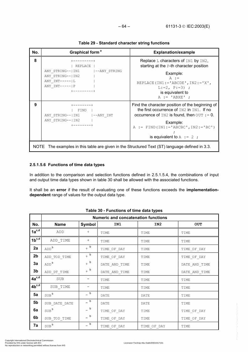
– 64 – 61131-3 IEC:2003(E)
Table 29 - Standard character string functions
No. Graphical form a Explanation/example
8 +---------+ | REPLACE |ANY_STRING--|IN1 |--ANY_STRINGANY_STRING--|IN2 |ANY_INT-----|L |ANY_INT-----|P | +---------+
Replace L characters of IN1 by IN2,starting at the P-th character position
Example:A :=
REPLACE(IN1:='ABCDE',IN2:='X',L:=2, P:=3) ;
is equivalent toA := 'ABXE' ;
9 +--------+ | FIND |ANY_STRING--|IN1 |--ANY_INTANY_STRING--|IN2 | +--------+
Find the character position of the beginning ofthe first occurrence of IN2 in IN1. If no
occurrence of IN2 is found, then OUT := 0.
Example:A := FIND(IN1:='ABCBC',IN2:='BC')
;is equivalent to A := 2 ;
NOTE The examples in this table are given in the Structured Text (ST) language defined in 3.3.
2.5.1.5.6 Functions of time data types
In addition to the comparison and selection functions defined in 2.5.1.5.4, the combinations of inputand output time data types shown in table 30 shall be allowed with the associated functions.
It shall be an error if the result of evaluating one of these functions exceeds the implementation-dependent range of values for the output data type.
Table 30 - Functions of time data typesNumeric and concatenation functions
No. Name Symbol IN1 IN2 OUT
1ac,d ADD + TIME TIME TIME
1bc,d ADD_TIME + TIME TIME TIME
2a ADD b + bTIME_OF_DAY TIME TIME_OF_DAY
2b ADD_TOD_TIME + bTIME_OF_DAY TIME TIME_OF_DAY
3a ADD b + bDATE_AND_TIME TIME DATE_AND_TIME
3b ADD_DT_TIME + bDATE_AND_TIME TIME DATE_AND_TIME
4ac,d SUB - TIME TIME TIME
4bc,d SUB_TIME - TIME TIME TIME
5a SUB b - bDATE DATE TIME
5b SUB_DATE_DATE - bDATE DATE TIME
6a SUB b - bTIME_OF_DAY TIME TIME_OF_DAY
6b SUB_TOD_TIME - bTIME_OF_DAY TIME TIME_OF_DAY
7a SUB b - bTIME_OF_DAY TIME_OF_DAY TIME
Copyright International Electrotechnical Commission Provided by IHS under license with IEC Licensee=Technip Abu Dabhi/5931917101
Not for Resale, 02/12/2006 07:01:30 MSTNo reproduction or networking permitted without license from IHS
--``,`,`,,,``````,,``,,``,,,,`,-`-`,,`,,`,`,,`---

61131-3 IEC:2003(E) – 65 –
Table 30 - Functions of time data typesNumeric and concatenation functions
No. Name Symbol IN1 IN2 OUT
7b SUB_TOD_TOD - bTIME_OF_DAY TIME_OF_DAY TIME
8a SUB b - bDATE_AND_TIME TIME DATE_AND_TIME
8b SUB_DT_TIME - bDATE_AND_TIME TIME DATE_AND_TIME
9a SUB b - bDATE_AND_TIME DATE_AND_TIME TIME
9b SUB_DT_DT - bDATE_AND_TIME DATE_AND_TIME TIME
10a MUL b * bTIME ANY_NUM TIME
10b MULTIME * bTIME ANY_NUM TIME
11a DIV b / bTIME ANY_NUM TIME
11b DIVTIME / bTIME ANY_NUM TIME
12 CONCAT_DATE_TOD DATE TIME_OF_DAY DATE_AND_TIME
Type conversion functions
13a
14aDT_TO_TODDT_TO_DATE
NOTE 1 Non-blank entries in the Symbol column are suitable for use as operators in textuallanguages, as shown in tables 52 and 55.
NOTE 2 The notations IN1, IN2, ..., INn refer to the inputs in top-to-bottom order; OUT refers tothe output.
NOTE 3 It is possible to type the functions MULTIME and DIVTIME, e.g., the operands ofMULTIME_REAL would be of type TIME and REAL, respectively.
NOTE 4 The effects of conversion between time data types and types STRING and WSTRINGare defined in footnote (e) of table 22.
NOTE 5 The effects of type conversions between time data types and other data types notdefined in this table are implementation-dependent.
a The type conversion functions shall have the effect of “extracting” the appropriate data, e.g., theST language statements
X := DT#1986-04-28-08:40:00 ;Y := DT_TO_TOD(X) ;W := DT_TO_DATE(X);
shall have the same result as the statementsX := DT#1986-04-28-08:40:00 ;W := DATE#1986-04-28 ;Y := TIME_OF_DAY#08:40:00;.b This usage is deprecated and will not be included in future editions of this standard.c When the named representation of a function is supported, this shall be indicated by the suffix “n”
in the compliance statement. For example, “1n” represents the notation “ADD”.d When the symbolic representation of a function is supported, this shall be indicated by the suffix
“s” in the compliance statement. For example, “1s” represents the notation “+”.
Copyright International Electrotechnical Commission Provided by IHS under license with IEC Licensee=Technip Abu Dabhi/5931917101
Not for Resale, 02/12/2006 07:01:30 MSTNo reproduction or networking permitted without license from IHS
--``,`,`,,,``````,,``,,``,,,,`,-`-`,,`,,`,`,,`---

– 66 – 61131-3 IEC:2003(E)
2.5.1.5.7 Functions of enumerated data types
The selection and comparison functions listed in table 31 can be applied to inputs which are of anenumerated data type as defined in 2.3.3.1.
Table 31 - Functions of enumerated data types
No. Name Symbol Feature No. in tables 27 and 28
1 SEL 1
2 MUX 4
3aEQ = 7
4aNE <> 10
NOTE The provisions of NOTES 1-2 of table 28 apply to this table.a The provisions of footnotes a and b of table 28 apply to this feature.
2.5.2 Function blocks
For the purposes of programmable controller programming languages, a function block is a programorganization unit which, when executed, yields one or more values. Multiple, named instances(copies) of a function block can be created. Each instance shall have an associated identifier (theinstance name), and a data structure containing its output and internal variables, and, depending onthe implementation, values of or references to its input variables. All the values of the output variablesand the necessary internal variables of this data structure shall persist from one execution of thefunction block to the next; therefore, invocation of a function block with the same arguments (inputvariables) need not always yield the same output values.
Only the input and output variables shall be accessible outside of an instance of a function block, i.e.,the function block's internal variables shall be hidden from the user of the function block.
Execution of the operations of a function block shall be invoked as defined in clause 3 for textuallanguages, according to the rules of network evaluation given in clause 4 for graphic languages, orunder the control of sequential function chart (SFC) elements as defined in 2.6.
Any function block type which has already been declared can be used in the declaration of anotherfunction block type or program type as shown in figure 3.
The scope of an instance of a function block shall be local to the program organization unit in which itis instantiated, unless it is declared to be global in a VAR_GLOBAL block as defined in 2.7.1.
As illustrated in 2.5.2.2, the instance name of a function block instance can be used as the input to afunction or function block if declared as an input variable in a VAR_INPUT declaration, or as aninput/output variable of a function block in a VAR_IN_OUT declaration, as defined in 2.4.3.
The maximum number of function block types and instantiations for a given resource areimplementation-dependent parameters.
Copyright International Electrotechnical Commission Provided by IHS under license with IEC Licensee=Technip Abu Dabhi/5931917101
Not for Resale, 02/12/2006 07:01:30 MSTNo reproduction or networking permitted without license from IHS
--``,`,`,,,``````,,``,,``,,,,`,-`-`,,`,,`,`,,`---

61131-3 IEC:2003(E) – 67 –
2.5.2.1 Representation
As illustrated in figure 9, an instance of a function block can be created textually, by declaring a dataelement using the declared function block type in a VAR...END_VAR construct, identically to the useof a structured data type, as defined in 2.4.3.
As further illustrated in figure 9, an instance of a function block can be created graphically, by using agraphic representation of the function block, with the function block type name inside the block, andthe instance name above the block, following the rules for representation of functions given in 2.5.1.1.
As shown in figure 9, input and output variables of an instance of a function block can be representedas elements of structured data types as defined in 2.3.3.1.
If either of the two graphical negation features defined in table 19 is supported for function blocks, itshall also be supported for functions as defined in 2.5.1, and vice versa.
Graphical (FBD language) Textual (ST language)
FF75 +------+ | SR | %IX1---|S1 Q1|---%QX3 %IX2---|R | +------+
VAR FF75: SR; END_VAR (* Declaration *)
FF75(S1:=%IX1, R:=%IX2); (* Invocation *)
%QX3 := FF75.Q1 ; (* Assign Output *)
MyTon +-------+ +----+ | TON |a--| NE |---O|EN ENO|--b--| | r--|IN Q|O-out +----+ --|PT ET|-- +-------+
VAR a,b,r,out : BOOL; MyTon : TON; END_VAR
MyTon(EN := NOT (a <> b), IN := r, NOT Q => out);
Figure 9 - Function block instantiation examples
Assignment of a value to an output variable of a function block is not allowed except from within thefunction block. The assignment of a value to the input of a function block is permitted only as part ofthe invocation of the function block. Unassigned or unconnected inputs of a function block shall keeptheir initialized values or the values from the latest previous invocation, if any. Allowable usages offunction block inputs and outputs are summarized in table 32, using the function block FF75 of typeSR shown in figure 9. The examples are shown in the ST language.
IEC 2479/02
Copyright International Electrotechnical Commission Provided by IHS under license with IEC Licensee=Technip Abu Dabhi/5931917101
Not for Resale, 02/12/2006 07:01:30 MSTNo reproduction or networking permitted without license from IHS
--``,`,`,,,``````,,``,,``,,,,`,-`-`,,`,,`,`,,`---

– 68 – 61131-3 IEC:2003(E)
Table 32 - Examples of function block I/O variable usage
Usage Inside function block Outside function block
Input read IF IN1 THEN ... Not allowed (Notes 1 and 2)
Input assignment Not allowed (Note 1) FB_INST(IN1:=A,IN2:=B);
Output read OUT := OUT AND NOT IN2; C := FB_INST.OUT;
Output assignment OUT := 1; Not Allowed (Note 1)
In-out read IF INOUT THEN ... IF FB1.INOUT THEN...
In-out assignment INOUT := OUT OR IN1; (Note 3) FB_INST(INOUT:=D);
NOTE 1 Those usages listed as “not allowed” in this table could lead to implementation-dependent, unpredictable side effects.
NOTE 2 Reading and writing of input, output and internal variables of a function block maybe performed by the “communication function”, “operator interface function”, or the“programming, testing, and monitoring functions” defined in IEC 61131-1.
NOTE 3 As illustrated in 2.5.2.2, modification within the function block of a variable declaredin a VAR_IN_OUT block is permitted.
2.5.2.1a) Use of EN and ENO in function blocks
As shown in table 20 for functions, for function blocks an additional Boolean EN (Enable) input or ENO(Enable Out) output, or both, can also be provided by the manufacturer or user according to thedeclarations
VAR_INPUT EN: BOOL := 1; END_VARVAR_OUTPUT ENO: BOOL; END_VAR
When these variables are used, the execution of the operations defined by the function block shall becontrolled according to the following rules:
1) If the value of EN is FALSE (0) when the function block instance is invoked, the assignmentsof actual values to the function block inputs may or may not be made in an implementation-dependent fashion, the operations defined by the function block body shall not be executedand the value of ENO shall be reset to FALSE (0) by the programmable controller system.
2) Otherwise, the value of ENO shall be set to TRUE (1) by the programmable controller system,the assignments of actual values to the function block inputs shall be made and the operationsdefined by the function block body shall be executed. These operations can include theassignment of a Boolean value to ENO.
3) If the ENO output is evaluated to FALSE (0), the values of the function block outputs(VAR_OUTPUT) keep their states from the previous invocation.
NOTE It is a consequence of these rules that the ENO output of a function block must be explicitlyexamined by the invoking entity if necessary to account for possible error conditions.
EXAMPLES The figures below illustrate the use of EN and ENO in association with the standardTP, TON and TOF blocks (represented by T**) defined in subclause 2.5.2.3.4, and theCTU and CTD blocks (represented by CT*) defined in subclause 2.5.2.3.3. In accordancewith the above rules, a FALSE value of the EN input may be used to “freeze” the operationof the associated function block; that is, the output values do not change irrespective ofchanges in any of the other input values. When the EN input value becomes TRUE, normal
Copyright International Electrotechnical Commission Provided by IHS under license with IEC Licensee=Technip Abu Dabhi/5931917101
Not for Resale, 02/12/2006 07:01:30 MSTNo reproduction or networking permitted without license from IHS
--``,`,`,,,``````,,``,,``,,,,`,-`-`,,`,,`,`,,`---

61131-3 IEC:2003(E) – 69 –
operation of the function block may resume. The value of the ENO output is FALSE aftereach evaluation of the function block for which the EN input is FALSE. When EN is TRUE, aTRUE value of ENO reflects a normal evaluation of the block, and a FALSE value of ENOmay be used to indicate an implementation-dependent error condition.
+-------+ +-------+ | T** | | CT* | BOOL---|EN ENO|---BOOL BOOL---|EN ENO|---BOOL BOOL---|IN Q|---BOOL BOOL--->CU Q|---BOOL TIME---|PT ET|---TIME BOOL---|R CV|---INT +-------+ INT---|PV | +-------+
2.5.2.2 Declaration
As illustrated in figure 10, a function block shall be declared textually or graphically in the samemanner as defined for functions in 2.5.1.3, with the differences described below and summarized intable 33:
1) The delimiting keywords for declaration of function blocks shall beFUNCTION_BLOCK...END_FUNCTION_BLOCK.
2) The RETAIN qualifier defined in 2.4.3 can be used for internal and output variables of a functionblock, as shown in features 1, 2, and 3 in table 33.
3) The values of variables which are passed to the function block via a VAR_EXTERNAL constructcan be modified from within the function block, as shown in feature 10 of table 33.
4) The output values of a function block instance whose name is passed into the function block viaa VAR_INPUT, VAR_IN_OUT, or VAR_EXTERNAL construct can be accessed, but not modified,from within the function block, as shown in features 5, 6, and 7 of table 33.
5) A function block whose instance name is passed into the function block via a VAR_IN_OUT orVAR_EXTERNAL construction can be invoked from inside the function block, as shown infeatures 6 and 7 of table 33.
6) In textual declarations, the R_EDGE and F_EDGE qualifiers can be used to indicate an edge-detection function on Boolean inputs. This shall cause the implicit declaration of a functionblock of type R_TRIG or F_TRIG, respectively, as defined in 2.5.2.3.2, to perform the requirededge detection. For an example of this construction, see features 8a and 8b of table 33 and theaccompanying NOTE.
7) The construction illustrated in features 9a and 9b of table 33 shall be used in graphicaldeclarations for rising and falling edge detection. When the character set defined in 2.1.1 isused, the “greater than” (>) or “less than” (<) character shall be in line with the edge of thefunction block. When graphic or semigraphic representations are employed, the notation of IEC60617-12 for dynamic inputs shall be used.
8) If the generic data types given in table 11 are used in the declaration of standard function blockinputs and outputs, then the rules for inferring the actual types of the outputs of such functionblock types shall be part of the function block type definition. In textual invocations of suchfunction blocks assignments of the outputs to variables shall be made directly in the invocationstatement (using the operator ‘=>‘).
9) The asterisk notation (feature No. 10 in table 15) can be used in the declaration of internalvariables of a function block.
10) EN/ENO inputs and outputs shall be declared and used as described in 2.5.1.2a).
11) It shall be an error if no value is specified for: (i) an in-out variable of a function block instance;(ii) a function block instance used as an input variable of another function block instance.
Copyright International Electrotechnical Commission Provided by IHS under license with IEC Licensee=Technip Abu Dabhi/5931917101
Not for Resale, 02/12/2006 07:01:30 MSTNo reproduction or networking permitted without license from IHS
--``,`,`,,,``````,,``,,``,,,,`,-`-`,,`,,`,`,,`---

– 70 – 61131-3 IEC:2003(E)
As illustrated in figure 12, only variables or function block instance names can be passed into afunction block via the VAR_IN_OUT construct, i.e., function or function block outputs cannot be passedvia this construction. This is to prevent the inadvertent modifications of such outputs. However,“cascading” of VAR_IN_OUT constructions is permitted, as illustrated in figure 12 c).
(* a) Textual declaration in ST language (see 3.3) *)
FUNCTION_BLOCK DEBOUNCE(*** External Interface ***)VAR_INPUT IN : BOOL ; (* Default = 0 *) DB_TIME : TIME := t#10ms ; (* Default = t#10ms *)END_VARVAR_OUTPUT OUT : BOOL ; (* Default = 0 *) ET_OFF : TIME ; (* Default = t#0s *)END_VARVAR DB_ON : TON ; (** Internal Variables **) DB_OFF : TON ; (** and FB Instances **) DB_FF : SR ;END_VAR
(** Function Block Body **)DB_ON(IN := IN, PT := DB_TIME) ;DB_OFF(IN := NOT IN, PT:=DB_TIME) ;DB_FF(S1 :=DB_ON.Q, R := DB_OFF.Q) ;OUT := DB_FF.Q ;ET_OFF := DB_OFF.ET ;
END_FUNCTION_BLOCK
(* b) Graphical declaration in FBD language (see 4.3) *)
FUNCTION_BLOCK(** External Interface **) +---------------+ | DEBOUNCE | BOOL---|IN OUT|---BOOL TIME---|DB_TIME ET_OFF|---TIME +---------------+(** Function Block Body **)
DB_ON DB_FF +-----+ +----+ | TON | | SR | IN----+------|IN Q|-----|S1 Q|---OUT | +---|PT ET| +--|R | | | +-----+ | +----+ | | | | | DB_OFF | | | +-----+ | | | | TON | | +--|--O|IN Q|--+ DB_TIME--+---|PT ET|--------------ET_OFF +-----+ END_FUNCTION_BLOCK
Figure 10 - Examples of function block declarationsIEC 2480/02
Copyright International Electrotechnical Commission Provided by IHS under license with IEC Licensee=Technip Abu Dabhi/5931917101
Not for Resale, 02/12/2006 07:01:30 MSTNo reproduction or networking permitted without license from IHS
--``,`,`,,,``````,,``,,``,,,,`,-`-`,,`,,`,`,,`---

61131-3 IEC:2003(E) – 71 –
Table 33 - Function block declaration and usage features
No. Description Example
1a RETAIN qualifier on internal variables VAR RETAIN X : REAL ; END_VAR
1b NON_RETAIN qualifier on internalvariables
VAR NON_RETAIN X : REAL ; END_VAR
2a RETAIN qualifier on output variables VAR_OUTPUT RETAIN X : REAL ; END_VAR
2b RETAIN qualifier on input variables VAR_INPUT RETAIN X : REAL ; END_VAR
2c RETAIN qualifier on output variables VAR_OUTPUT NON_RETAIN X : REAL ; END_VAR
2d RETAIN qualifier on input variables VAR_INPUT NON_RETAIN X : REAL ; END_VAR
3a RETAIN qualifier on internal function blocks VAR RETAIN TMR1: TON ; END_VAR
3b NON_RETAIN qualifier on internal function blocks VAR NON_RETAIN TMR1: TON ; END_VAR
4a VAR_IN_OUT declaration (textual) VAR_IN_OUT A: INT ; END_VAR
4b VAR_IN_OUT declaration and usage(graphical) See figure 12
4c VAR_IN_OUT declaration with assignment to different variables (graphical) See figure 12d
5a Function block instance name as input(textual)
VAR_INPUT I_TMR: TON ; END_VAREXPIRED := I_TMR.Q; (* Note 1 *)
5b Function block instance name as input (graphical) See figure 11a6a Function block instance name as
VAR_IN_OUT (textual)VAR_IN_OUT IO_TMR: TOF ; END_VARIO_TMR(IN:=A_VAR, PT:=T#10S);EXPIRED := IO_TMR.Q; (* Note 1 *)
6b Function block instance name as VAR_IN_OUT (graphical) See figure 11b
7a Function block instance name as externalvariable (textual)
VAR_EXTERNAL EX_TMR : TOF ;END_VAREX_TMR(IN:=A_VAR, PT:=T#10S);EXPIRED := EX_TMR.Q; (* Note 1 *)
7b Function block instance name as external variable (graphical) See figure 11c
8a8b
Textual declaration of:rising edge inputsfalling edge inputs
FUNCTION_BLOCK AND_EDGE (* Note 2 *)VAR_INPUT X : BOOL R_EDGE; Y : BOOL F_EDGE;END_VARVAR_OUTPUT Z : BOOL ; END_VARZ := X AND Y ; (* ST language example *)END_FUNCTION_BLOCK (*- see 3.3 *)
9a
9b
Graphical declaration of:rising edge inputs
falling edge inputs
FUNCTION_BLOCK (* Note 2 *) +-----------+ (* External interface *) | AND_EDGE |BOOL---->X Z|---BOOL | |BOOL----<Y | | | +-----------+ +---+ (* Function block body *) X---| & |---Z (* FBD language example *) Y---| | (* - see 4.3 *) +---+END_FUNCTION_BLOCK
10a VAR_EXTERNAL declarations within function block type declarations
Copyright International Electrotechnical Commission Provided by IHS under license with IEC Licensee=Technip Abu Dabhi/5931917101
Not for Resale, 02/12/2006 07:01:30 MSTNo reproduction or networking permitted without license from IHS
--``,`,`,,,``````,,``,,``,,,,`,-`-`,,`,,`,`,,`---

– 72 – 61131-3 IEC:2003(E)
Table 33 - Function block declaration and usage features
No. Description Example
10b VAR_EXTERNAL CONSTANT declarations within function block type declarations11 VAR_TEMP declarations (see 2.4.3) within function block type declarations
NOTE 1 It is assumed in these examples that the variables EXPIRED and A_VAR have beendeclared of type BOOL.
NOTE 2 The declaration of function block AND_EDGE in the above examples is equivalent to:
FUNCTION_BLOCK AND_EDGE VAR INPUT X : BOOL; Y : BOOL; END_VAR VAR X_TRIG : R_TRIG ; Y_TRIG : F_TRIG ; END_VAR X_TRIG(CLK := X) ; Y_TRIG(CLK := Y) ; Z := X_TRIG.Q AND Y_TRIG.Q; END_FUNCTION_BLOCK
See 2.5.2.3.2 for the definition of the edge detection function blocks R_TRIG andF_TRIG.
Copyright International Electrotechnical Commission Provided by IHS under license with IEC Licensee=Technip Abu Dabhi/5931917101
Not for Resale, 02/12/2006 07:01:30 MSTNo reproduction or networking permitted without license from IHS
--``,`,`,,,``````,,``,,``,,,,`,-`-`,,`,,`,`,,`---
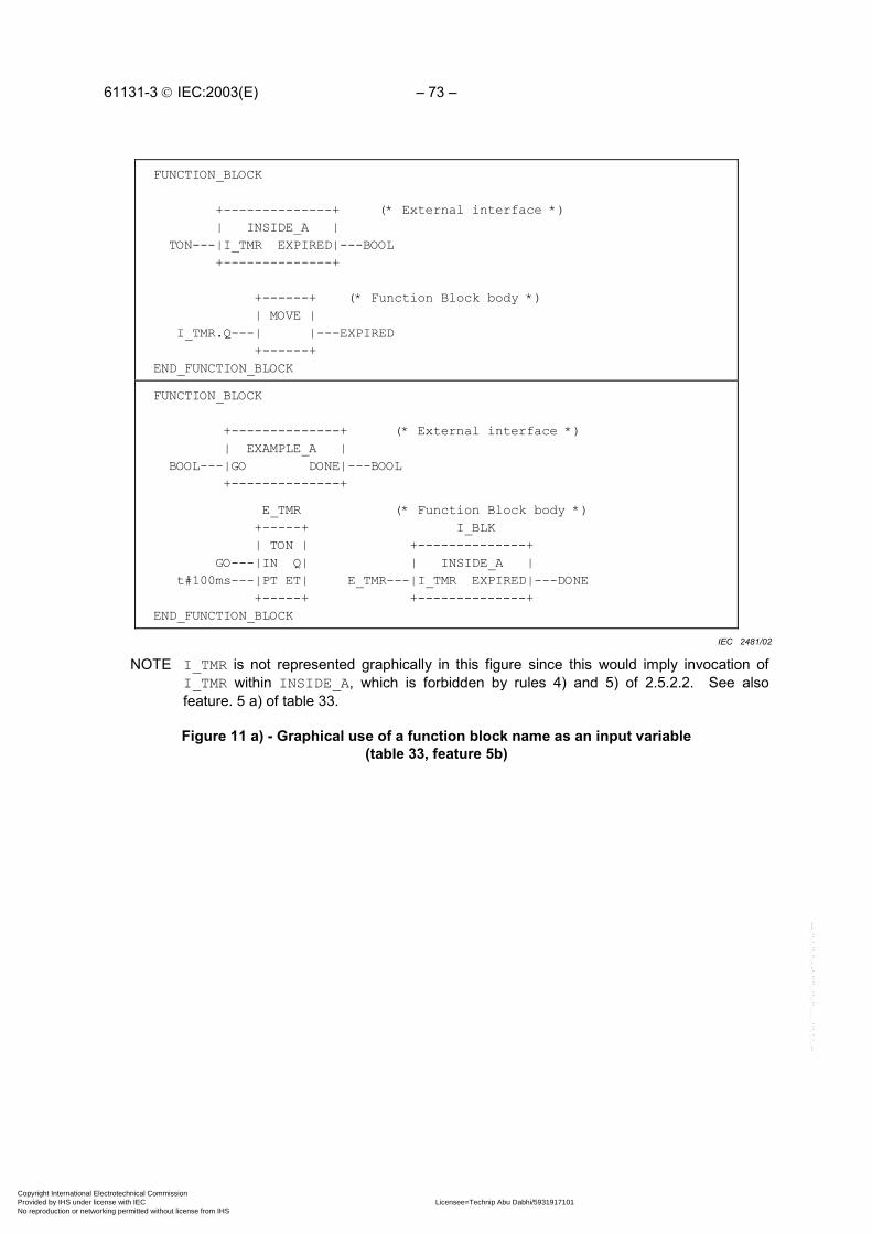
61131-3 IEC:2003(E) – 73 –
FUNCTION_BLOCK
+--------------+ (* External interface *) | INSIDE_A | TON---|I_TMR EXPIRED|---BOOL +--------------+
+------+ (* Function Block body *) | MOVE | I_TMR.Q---| |---EXPIRED +------+END_FUNCTION_BLOCK
FUNCTION_BLOCK
+--------------+ (* External interface *) | EXAMPLE_A | BOOL---|GO DONE|---BOOL +--------------+
E_TMR (* Function Block body *) +-----+ I_BLK | TON | +--------------+ GO---|IN Q| | INSIDE_A | t#100ms---|PT ET| E_TMR---|I_TMR EXPIRED|---DONE +-----+ +--------------+END_FUNCTION_BLOCK
NOTE I_TMR is not represented graphically in this figure since this would imply invocation ofI_TMR within INSIDE_A, which is forbidden by rules 4) and 5) of 2.5.2.2. See alsofeature. 5 a) of table 33.
Figure 11 a) - Graphical use of a function block name as an input variable(table 33, feature 5b)
IEC 2481/02
Copyright International Electrotechnical Commission Provided by IHS under license with IEC Licensee=Technip Abu Dabhi/5931917101
Not for Resale, 02/12/2006 07:01:30 MSTNo reproduction or networking permitted without license from IHS
--``,`,`,,,``````,,``,,``,,,,`,-`-`,,`,,`,`,,`---

– 74 – 61131-3 IEC:2003(E)
FUNCTION_BLOCK +--------------+ (* External interface *) | INSIDE_B | TON---|I_TMR----I_TMR|---TON BOOL--|TMR_GO EXPIRED|---BOOL +--------------+
I_TMR (* Function Block body *) +-----+ | TON | TMR_GO--|IN Q|---EXPIRED |PT ET| +-----+END_FUNCTION_BLOCK
FUNCTION_BLOCK
+--------------+ (* External interface *) | EXAMPLE_B | BOOL---|GO DONE|---BOOL +--------------+
E_TMR (* Function Block body *) +-----+ I_BLK | TON | +---------------+ |IN Q| | INSIDE_B | t#100ms---|PT ET| E_TMR---|I_TMR-----I_TMR| +-----+ GO------|TMR_GO EXPIRED|---DONE +---------------+END_FUNCTION_BLOCK
Figure 11 b) - Graphical use of a function block name as an in-out variable(table 33, feature 6b)
IEC 2482/02
Copyright International Electrotechnical Commission Provided by IHS under license with IEC Licensee=Technip Abu Dabhi/5931917101
Not for Resale, 02/12/2006 07:01:30 MSTNo reproduction or networking permitted without license from IHS
--``,`,`,,,``````,,``,,``,,,,`,-`-`,,`,,`,`,,`---

61131-3 IEC:2003(E) – 75 –
FUNCTION_BLOCK +--------------+ (* External interface *) | INSIDE_C | BOOL--|TMR_GO EXPIRED|---BOOL +--------------+
VAR_EXTERNAL X_TMR : TON ; END_VAR
X_TMR (* Function Block body *) +-----+ | TON | TMR_GO---|IN Q|---EXPIRED |PT ET| +-----+END_FUNCTION_BLOCK
PROGRAM +--------------+ (* External interface *) | EXAMPLE_C | BOOL---|GO DONE|---BOOL +--------------+
VAR_GLOBAL X_TMR : TON ; END_VAR
I_BLK (* Program body *) +---------------+ | INSIDE_C | GO------|TMR_GO EXPIRED|---DONE +---------------+END_PROGRAM
NOTE The PROGRAM declaration mechanism is defined in 2.5.3.
Figure 11 c) - Graphical use of a function block name as an external variable(table 33, feature 7b)
IEC 2483/02
Copyright International Electrotechnical Commission Provided by IHS under license with IEC Licensee=Technip Abu Dabhi/5931917101
Not for Resale, 02/12/2006 07:01:30 MSTNo reproduction or networking permitted without license from IHS
--``,`,`,,,``````,,``,,``,,,,`,-`-`,,`,,`,`,,`---

– 76 – 61131-3 IEC:2003(E)
12a) +-------+ | ACCUM | INT---|A-----A|---INT INT---|X | +-------+ +---+ A---| + |---A X---| | +---+
FUNCTION_BLOCK ACCUM VAR_IN_OUT A : INT ; END_VAR VAR_INPUT X : INT ; END_VAR A := A+X ;END_FUNCTION_BLOCK
12b) ACC1 +-------+ | ACCUM | ACC----------|A-----A|---ACC +---+ | | X1---| * |---|X | X2---| | +-------+ +---+
A declaration such asVAR ACC : INT ; X1 : INT ; X2 : INT ;END_VARis assumed: the effect of execution isACC := ACC+X1*X2 ;
12c) ACC1 ACC2 +-------+ +-------+ | ACCUM | | ACCUM |ACC----------|A-----A|----------------|A-----A|---ACC +---+ | | +---+ | |X1---| * |---|X | X3---| * |---|X |X2---| | +-------+ X4---| | +-------+ +---+ +---+
Declarations as in12b) are assumed forACC, X1, X2, X3,and X4.; the effect ofexecution isACC :=ACC+X1*X2+X3*X4;
12d) ACC1 +-------+ | ACCUM | X3-----------|A-----A|---X4 +---+ | | X1---| * |---|X | X2---| | +-------+ +---+
A declaration such asVAR X1 : INT ; X2 : INT ;....X3 : INT ;... X4 : INT ;END_VARis assumed: the effect of execution isX3 := X3+X1*X2 ;X4 := X3 ;
12e) ACC1 +---+ +-------+ X1---| * | | ACCUM | X2---| |---|A-----A|---ACC +---+ | | X3-----------|X | +-------+
ILLEGAL USAGE!!!Connection to in-out variable A is not avariable or function block name (seepreceding text)
Figure 12 - Declaration and usage of in-out variables in function blocksa) Graphical and textual declarations
b), c), d) Legal usage, e) Illegal usage
IEC 2484/02
Copyright International Electrotechnical Commission Provided by IHS under license with IEC Licensee=Technip Abu Dabhi/5931917101
Not for Resale, 02/12/2006 07:01:30 MSTNo reproduction or networking permitted without license from IHS
--``,`,`,,,``````,,``,,``,,,,`,-`-`,,`,,`,`,,`---

61131-3 IEC:2003(E) – 77 –
2.5.2.3 Standard function blocks
Definitions of function blocks common to all programmable controller programming languages aregiven in this subclause.
Where graphical declarations of standard function blocks are shown in this subclause, equivalenttextual declarations, as specified in 2.5.2.2, can also be written, as for example in table 35.
Standard function blocks may be overloaded and may have extensible inputs and outputs. Thedefinitions of such function block types shall describe any constraints on the number and data types ofsuch inputs and outputs. The use of such capabilities in non-standard function blocks is beyond thescope of this Standard.
2.5.2.3.1 Bistable elements
The graphical form and function block body of standard bistable elements are shown in table 34. Thenotation for these elements is chosen to be as consistent as possible with symbols 12-09-01 and12-09-02 of IEC 60617-12.
Table 34 - Standard bistable function blocks a
No. Graphical form Function block body
1 Bistable function block (set dominant)
+-----+ | SR | BOOL---|S1 Q1|---BOOL BOOL---|R | +-----+
+-----+ S1----------------| >=1 |---Q1 +---+ | | R------O| & |----| | Q1------| | | | +---+ +-----+
2 Bistable function block (reset dominant)
+-----+ | RS | BOOL---|S Q1|---BOOL BOOL---|R1 | +-----+
+---+ R1----------------O| & |---Q1 +-----+ | | S-------| >=1 |----| | Q1------| | | | +-----+ +---+
NOTE The function block body is specified in the Function Block Diagram (FBD) languagedefined in 4.3.
a The initial state of the output variable Q1 shall be the normal default value of zero for Booleanvariables.
Copyright International Electrotechnical Commission Provided by IHS under license with IEC Licensee=Technip Abu Dabhi/5931917101
Not for Resale, 02/12/2006 07:01:30 MSTNo reproduction or networking permitted without license from IHS
--``,`,`,,,``````,,``,,``,,,,`,-`-`,,`,,`,`,,`---

– 78 – 61131-3 IEC:2003(E)
2.5.2.3.2 Edge detection
The graphic representation of standard rising- and falling-edge detecting function blocks shall be asshown in table 35. The behaviors of these blocks shall be equivalent to the definitions given in thistable. This behavior corresponds to the following rules:
1) The Q output of an R_TRIG function block shall stand at the BOOL#1 value from one executionof the function block to the next, following the 0 to 1 transition of the CLK input, and shall returnto 0 at the next execution.
2) The Q output of an F_TRIG function block shall stand at the BOOL#1 value from one executionof the function block to the next, following the 1 to 0 transition of the CLK input, and shall returnto 0 at the next execution.
Table 35 - Standard edge detection function blocks
No. Graphical form Definition(ST language - see 3.3)
1 Rising edge detector
+--------+ | R_TRIG | BOOL---|CLK Q|---BOOL +--------+
FUNCTION_BLOCK R_TRIG VAR_INPUT CLK: BOOL; END_VAR VAR_OUTPUT Q: BOOL; END_VAR VAR M: BOOL; END_VARQ := CLK AND NOT M;M := CLK;END_FUNCTION_BLOCK
2 Falling edge detector
+--------+ | F_TRIG | BOOL---|CLK Q|---BOOL +--------+
FUNCTION_BLOCK F_TRIG VAR_INPUT CLK: BOOL; END_VAR VAR_OUTPUT Q: BOOL; END_VAR VAR M: BOOL; END_VARQ := NOT CLK AND NOT M;M := NOT CLK;END_FUNCTION_BLOCK
NOTE When the CLK input of an instance of the R_TRIG type is connected to a value ofBOOL#1, its Q output will stand at BOOL#1 after its first execution following a “cold restart”as described in 2.4.2. The Q output will stand at BOOL#0 following all subsequentexecutions. The same applies to an F_TRIG instance whose CLK input is disconnectedor is connected to a value of FALSE.
2.5.2.3.3 Counters
The graphic representations of standard counter function blocks, with the types of the associatedinputs and outputs, shall be as shown in table 36. The operation of these function blocks shall be asspecified in the corresponding function block bodies.
Copyright International Electrotechnical Commission Provided by IHS under license with IEC Licensee=Technip Abu Dabhi/5931917101
Not for Resale, 02/12/2006 07:01:30 MSTNo reproduction or networking permitted without license from IHS
--``,`,`,,,``````,,``,,``,,,,`,-`-`,,`,,`,`,,`---

61131-3 IEC:2003(E) – 79 –
Table 36 - Standard counter function blocks
No. Graphical form Function block body(ST language - see 3.3)
Up-counter
1a +-----+ | CTU | BOOL--->CU Q|---BOOL BOOL---|R | INT---|PV CV|---INT +-----+
IF R THEN CV := 0 ; ELSIF CU AND (CV < PVmax) THEN CV := CV+1; END_IF ; Q := (CV >= PV) ;
1b +----------+ | CTU_DINT | BOOL--->CU Q|---BOOL BOOL---|R | DINT---|PV CV|---DINT +----------+
Same as 1a
1c +----------+ | CTU_LINT | BOOL--->CU Q|---BOOL BOOL---|R | LINT---|PV CV|---LINT +----------+
Same as 1a
1d +-----------+ | CTU_UDINT | BOOL--->CU Q|---BOOL BOOL---|R | UDINT---|PV CV|---UDINT +-----------+
Same as 1a
1e +-----------+ | CTU_ULINT | BOOL--->CU Q|---BOOL BOOL---|R | ULINT---|PV CV|---ULINT +-----------+
Same as 1a
Down-counter
2a +-----+ | CTD | BOOL--->CD Q|---BOOL BOOL---|LD | INT---|PV CV|---INT +-----+
IF LD THEN CV := PV ; ELSIF CD AND (CV > PVmin) THEN CV := CV-1; END_IF ; Q := (CV <= 0) ;
2b +----------+ | CTD_DINT | BOOL--->CD Q|---BOOL BOOL---|LD | DINT---|PV CV|---DINT +----------+
Same as 2a
Copyright International Electrotechnical Commission Provided by IHS under license with IEC Licensee=Technip Abu Dabhi/5931917101
Not for Resale, 02/12/2006 07:01:30 MSTNo reproduction or networking permitted without license from IHS
--``,`,`,,,``````,,``,,``,,,,`,-`-`,,`,,`,`,,`---

– 80 – 61131-3 IEC:2003(E)
Table 36 - Standard counter function blocks
No. Graphical form Function block body(ST language - see 3.3)
2c +----------+ | CTD_LINT | BOOL--->CD Q|---BOOL BOOL---|LD | LINT---|PV CV|---LINT +----------+
Same as 2a
2d +-----------+ | CTD_UDINT | BOOL--->CD Q|---BOOL BOOL---|LD | UDINT---|PV CV|---UDINT +-----------+
Same as 2a
2e +-----------+ | CTD_ULINT | BOOL--->CD Q|---BOOL BOOL---|LD | ULINT---|PV CV|---ULINT +-----------+
Same as 2a
Up-down counter3a +------+
| CTUD | BOOL--->CU QU|---BOOL BOOL--->CD QD|---BOOL BOOL---|R | BOOL---|LD | INT---|PV CV|---INT +------+
IF R THEN CV := 0 ; ELSIF LD THEN CV := PV ; ELSE IF NOT (CU AND CD) THEN IF CU AND (CV < PVmax) THEN CV := CV+1; ELSIF CD AND (CV > PVmin) THEN CV := CV-1; END_IF; END_IF; END_IF ; QU := (CV >= PV) ; QD := (CV <= 0) ;
3b +-----------+ | CTUD_DINT | BOOL--->CU QU|---BOOL BOOL--->CD QD|---BOOL BOOL---|R | BOOL---|LD | DINT---|PV CV|---DINT +-----------+
Same as 3a
3c +-----------+ | CTUD_LINT | BOOL--->CU QU|---BOOL BOOL--->CD QD|---BOOL BOOL---|R | BOOL---|LD | LINT---|PV CV|---LINT +-----------+
Same as 3a
Copyright International Electrotechnical Commission Provided by IHS under license with IEC Licensee=Technip Abu Dabhi/5931917101
Not for Resale, 02/12/2006 07:01:30 MSTNo reproduction or networking permitted without license from IHS
--``,`,`,,,``````,,``,,``,,,,`,-`-`,,`,,`,`,,`---

61131-3 IEC:2003(E) – 81 –
Table 36 - Standard counter function blocks
No. Graphical form Function block body(ST language - see 3.3)
3d +------------+ | CTUD_ULINT | BOOL--->CU QU|---BOOL BOOL--->CD QD|---BOOL BOOL---|R | BOOL---|LD | ULINT---|PV CV|---ULINT +------------+
Same as 3a
NOTE The numerical values of the limit variables PVmin and PVmax are implementation-dependent.
2.5.2.3.4 Timers
The graphic form for standard timer function blocks shall be as shown in table 37. The operation ofthese function blocks shall be as defined in the timing diagrams given in table 38.
Table 37 - Standard timer function blocks
No. Description Graphical form
12a
2b a
3a3b a
*** is: TP (Pulse)
TON (On-delay)
T---0 (On-delay)
TOF (Off-delay)
0---T (Off-delay)
+-------+ | *** | BOOL---|IN Q|---BOOL TIME---|PT ET|---TIME +-------+
NOTE The effect of a change in the value of the PT input during the timing operation, e.g., thesetting of PT to t#0s to reset the operation of a TP instance, is an implementation-dependent parameter.
a In textual languages, features 2b and 3b shall not be used.
Copyright International Electrotechnical Commission Provided by IHS under license with IEC Licensee=Technip Abu Dabhi/5931917101
Not for Resale, 02/12/2006 07:01:30 MSTNo reproduction or networking permitted without license from IHS
--``,`,`,,,``````,,``,,``,,,,`,-`-`,,`,,`,`,,`---

– 82 – 61131-3 IEC:2003(E)
Table 38 - Standard timer function blocks - timing diagrams
Pulse (TP) timing +--------+ ++ ++ +--------+ IN | | || || | | --+ +-----++-++---+ +--------- t0 t1 t2 t3 t4 t5
+----+ +----+ +----+ Q | | | | | | --+ +---------+ +--+ +------------- t0 t0+PT t2 t2+PT t4 t4+PT
PT +---+ + +---+ : / | /| / | ET : / | / | / | : / | / | / | : / | / | / | 0-+ +-----+ +--+ +--------- t0 t1 t2 t4 t5
On-delay (TON) timing
+--------+ +---+ +--------+ IN | | | | | | --+ +--------+ +---+ +------------- t0 t1 t2 t3 t4 t5
+---+ +---+ Q | | | | -------+ +---------------------+ +------------- t0+PT t1 t4+PT t5
PT +---+ +---+ : / | + / | ET : / | /| / | : / | / | / | : / | / | / | 0-+ +--------+ +---+ +------------- t0 t1 t2 t3 t4 t5
Off-delay (TOF) timing
+--------+ +---+ +--------+ IN | | | | | | ---+ +--------+ +---+ +----------- t0 t1 t2 t3 t4 t5
+-------------+ +---------------------+ Q | | | | ---+ +---+ +------ t0 t1+PT t2 t5+PT
PT +---+ +------ : / | + / ET : / | /| / : / | / | / : / | / | / 0------------+ +---+ +--------+ t1 t3 t5
Copyright International Electrotechnical Commission Provided by IHS under license with IEC Licensee=Technip Abu Dabhi/5931917101
Not for Resale, 02/12/2006 07:01:30 MSTNo reproduction or networking permitted without license from IHS
--``,`,`,,,``````,,``,,``,,,,`,-`-`,,`,,`,`,,`---

61131-3 IEC:2003(E) – 83 –
2.5.2.3.5 Communication function blocks
Standard communication function blocks for programmable controllers are defined in IEC 61131-5.These function blocks provide programmable communications functionality such as device verification,polled data acquisition, programmed data acquisition, parametric control, interlocked control,programmed alarm reporting, and connection management and protection.
2.5.3 Programs
A program is defined in IEC 61131-1 as a “logical assembly of all the programming language elementsand constructs necessary for the intended signal processing required for the control of a machine orprocess by a programmable controller system.”
Subclause 1.4.1 of this part describes the place of programs in the overall software model of aprogrammable controller; subclause 1.4.2 describes the means available for inter- and intra-programcommunication; and subclause 1.4.3 describes the overall process of program development.
The declaration and usage of programs is identical to that of function blocks as defined in 2.5.2.1 and2.5.2.2, with the additional features shown in table 39 and the following differences:
1) The delimiting keywords for program declarations shall be PROGRAM...END_PROGRAM.
2) A program can contain a VAR_ACCESS...END_VAR construction, which provides a means ofspecifying named variables which can be accessed by some of the communication servicesspecified in IEC 61131-5. An access path associates each such variable with an input, output orinternal variable of the program. The format and usage of this declaration shall be as described in2.7.1 and in IEC 61131-5.
3) Programs can only be instantiated within resources, as defined in 2.7.1, while function blocks canonly be instantiated within programs or other function blocks.
4) A program can contain location assignments as described in 2.4.3.1 and 2.4.3.2 in thedeclarations of its global and internal variables. Location assignments with not fully specified directrepresentation as described in 2.4.1.1 and 2.4.3.1 can only be used in the declaration of internalvariables of a program.
The declaration and use of programs are illustrated in figure 19, and in examples F.7 and F.8.
Limitations on the size of programs in a particular resource are implementation-dependent parameters.
Table 39 - Program declaration features
No. DESCRIPTION
1 to 9b Same as features 1 to 9b, respectively, of table 3310 Formal input and output variables
11 to 14 Same as features 1 to 4, respectively, of table 1715 to 18 Same as features 1 to 4, respectively, of table 18
19 Use of directly represented variables (subclause 2.4.1.1)20 VAR_GLOBAL...END_VAR declaration within a PROGRAM (see 2.4.3 and 2.7.1)21 VAR_ACCESS...END_VAR declaration within a PROGRAM22a VAR_EXTERNAL declarations within PROGRAM type declarations22b VAR_EXTERNAL CONSTANT declarations within PROGRAM type declarations23 VAR_GLOBAL CONSTANT declarations within PROGRAM type declarations24 VAR_TEMP declarations (see 2.4.3) within PROGRAM type declarations
Copyright International Electrotechnical Commission Provided by IHS under license with IEC Licensee=Technip Abu Dabhi/5931917101
Not for Resale, 02/12/2006 07:01:30 MSTNo reproduction or networking permitted without license from IHS
--``,`,`,,,``````,,``,,``,,,,`,-`-`,,`,,`,`,,`---
– 84 – 61131-3 IEC:2003(E)
2.6 Sequential Function Chart (SFC) elements
2.6.1 General
This subclause defines sequential function chart (SFC) elements for use in structuring the internalorganization of a programmable controller program organization unit, written in one of the languagesdefined in this standard, for the purpose of performing sequential control functions. The definitions inthis subclause are derived from IEC 60848, with the changes necessary to convert the representationsfrom a documentation standard to a set of execution control elements for a programmable controllerprogram organization unit.
The SFC elements provide a means of partitioning a programmable controller program organizationunit into a set of steps and transitions interconnected by directed links. Associated with each step is aset of actions, and with each transition is associated a transition condition.
Since SFC elements require storage of state information, the only program organization units whichcan be structured using these elements are function blocks and programs.
If any part of a program organization unit is partitioned into SFC elements, the entire programorganization unit shall be so partitioned. If no SFC partitioning is given for a program organizationunit, the entire program organization unit shall be considered to be a single action which executesunder the control of the invoking entity.
2.6.2 Steps
A step represents a situation in which the behavior of a program organization unit with respect to itsinputs and outputs follows a set of rules defined by the associated actions of the step. A step is eitheractive or inactive. At any given moment, the state of the program organization unit is defined by theset of active steps and the values of its internal and output variables.
As shown in table 40, a step shall be represented graphically by a block containing a step name in theform of an identifier as defined in 2.1.2, or textually by a STEP...END_STEP construction. Thedirected link(s) into the step can be represented graphically by a vertical line attached to the top of thestep. The directed link(s) out of the step can be represented by a vertical line attached to the bottomof the step. Alternatively, the directed links can be represented textually by the TRANSITION...END_TRANSITION construction defined in 2.6.3.
The step flag (active or inactive state of a step) can be represented by the logic value of a Booleanstructure element ***.X, where *** is the step name, as shown in table 40. This Boolean variablehas the value 1 when the corresponding step is active, and 0 when it is inactive. The state of thisvariable is available for graphical connection at the right side of the step as shown in table 40.
Similarly, the elapsed time, ***.T, since initiation of a step can be represented by a structure elementof type TIME, as shown in table 40. When a step is deactivated, the value of the step elapsed timeshall remain at the value it had when the step was deactivated. When a step is activated, the value ofthe step elapsed time shall be reset to t#0s.
The scope of step names, step flags, and step times shall be local to the program organization unit inwhich the steps appear.
The initial state of the program organization unit is represented by the initial values of its internal andoutput variables, and by its set of initial steps, i.e., the steps which are initially active. Each SFCnetwork, or its textual equivalent, shall have exactly one initial step.
An initial step can be drawn graphically with double lines for the borders. When the character setdefined in 2.1.1 is used for drawing, the initial step shall be drawn as shown in table 40.
Copyright International Electrotechnical Commission Provided by IHS under license with IEC Licensee=Technip Abu Dabhi/5931917101
Not for Resale, 02/12/2006 07:01:30 MSTNo reproduction or networking permitted without license from IHS
--``,`,`,,,``````,,``,,``,,,,`,-`-`,,`,,`,`,,`---

61131-3 IEC:2003(E) – 85 –
For system initialization as defined in 2.4.2, the default initial elapsed time for steps is t#0s, and thedefault initial state is BOOL#0 for ordinary steps and BOOL#1 for initial steps. However, when aninstance of a function block or a program is declared to be retentive (for instance, as in feature 3 oftable 33), the states and (if supported) elapsed times of all steps contained in the program or functionblock shall be treated as retentive for system initialization as defined in 2.4.2.
The maximum number of steps per SFC and the precision of step elapsed time are implementation-dependent parameters.
It shall be an error if:1) an SFC network does not contain exactly one initial step;2) a user program attempts to assign a value directly to the step state or the step time.
Table 40 - Step featuresNo. REPRESENTATION DESCRIPTION1 |
+-----+ | *** | +-----+ |
Step - graphical formwith directed links"***" = step name
| +=======+ || *** || || || +=======+ |
Initial step - graphical form with directed links"***" = name of initial step
2 STEP *** : (* Step body *)END_STEP
Step - textual formwithout directed links (see 2.6.3)
"***" = step name
INITIAL_STEP *** :
(* Step body *)END_STEP
Initial step - textual formwithout directed links (see 2.6.3)"***" = name of initial step
3a a***.X
Step flag - general form"***" = step name
***.X = BOOL#1 when *** is active, BOOL#0 otherwise
3b a
| +-----+ | *** |---- +-----+ |
Step flag - direct connectionof Boolean variable ***.X to
right side of step "***"
4 a***.T
Step elapsed time - general form"***" = step name
***.T = a variable of type TIME(See 2.6.2)
NOTE The upper directed link to an initial step is not present if it has no predecessors.a When feature 3a, 3b, or 4 is supported, it shall be an error if the user program attempts
to modify the associated variable. For example, if S4 is a step name, then the followingstatements would be errors in the ST language defined in 3.3:
S4.X := 1 ; (* ERROR *)S4.T := t#100ms ; (* ERROR *)
Copyright International Electrotechnical Commission Provided by IHS under license with IEC Licensee=Technip Abu Dabhi/5931917101
Not for Resale, 02/12/2006 07:01:30 MSTNo reproduction or networking permitted without license from IHS
--``,`,`,,,``````,,``,,``,,,,`,-`-`,,`,,`,`,,`---

– 86 – 61131-3 IEC:2003(E)
2.6.3 Transitions
A transition represents the condition whereby control passes from one or more steps preceding thetransition to one or more successor steps along the corresponding directed link. The transition shallbe represented by a horizontal line across the vertical directed link.
The direction of evolution following the directed links shall be from the bottom of the predecessorstep(s) to the top of the successor step(s).
Each transition shall have an associated transition condition which is the result of the evaluation of asingle Boolean expression. A transition condition which is always true shall be represented by thesymbol 1 or the keyword TRUE.
A transition condition can be associated with a transition by one of the following means, as shown intable 41:
1) By placing the appropriate Boolean expression in the ST language defined in 3.3 physically orlogically adjacent to the vertical directed link.
2) By a ladder diagram network in the LD language defined in 4.2, physically or logically adjacent tothe vertical directed link.
3) By a network in the FBD language defined in 4.3, physically or logically adjacent to the verticaldirected link.
4) By a LD or FBD network whose output intersects the vertical directed link via a connector asdefined in 4.1.1.
5) By a TRANSITION...END_TRANSITION construct using the ST language. This shall consist of:- the keywords TRANSITION FROM followed by the step name of the predecessor step (or, if there
is more than one predecessor, by a parenthesized list of predecessor steps);- the keyword TO followed by the step name of the successor step (or, if there is more than one
successor, by a parenthesized list of successor steps);- the assignment operator (:=), followed by a Boolean expression in the ST language, specifying
the transition condition;- the terminating keyword END_TRANSITION.
6) By a TRANSITION...END_TRANSITION construct using the IL language defined in 3.2. Thisshall consist of:- the keywords TRANSITION FROM followed by the step name of the predecessor step (or, if there
is more than one predecessor, by a parenthesized list of predecessor steps), followed by acolon (:);
- the keyword TO followed by the step name of the successor step (or, if there is more than onesuccessor, by a parenthesized list of successor steps);
- beginning on a separate line, a list of instructions in the IL language, the result of whoseevaluation determines the transition condition;
- the terminating keyword END_TRANSITION on a separate line.
7) By the use of a transition name in the form of an identifier to the right of the directed link. Thisidentifier shall refer to a TRANSITION...END_TRANSITION construction defining one of thefollowing entities, whose evaluation shall result in the assignment of a Boolean value to thevariable denoted by the transition name:- a network in the LD or FBD language;- a list of instructions in the IL language;- an assignment of a Boolean expression in the ST language.
Copyright International Electrotechnical Commission Provided by IHS under license with IEC Licensee=Technip Abu Dabhi/5931917101
Not for Resale, 02/12/2006 07:01:30 MSTNo reproduction or networking permitted without license from IHS
--``,`,`,,,``````,,``,,``,,,,`,-`-`,,`,,`,`,,`---

61131-3 IEC:2003(E) – 87 –
The scope of a transition name shall be local to the program organization unit in which the transition islocated.
It shall be an error in the sense of 1.5.1 if any “side effect” (for instance, the assignment of a value toa variable other than the transition name) occurs during the evaluation of a transition condition.
The maximum number of transitions per SFC and per step are implementation-dependentparameters.
Table 41 - Transitions and transition conditions
No. Example Description
1a
| +-----+ |STEP7| +-----+ | + %IX2.4 & %IX2.3 | +-----+ |STEP8| +-----+ |
Predecessor step
Transition condition physically orlogically adjacent to the transition
using ST language (see 3.3)
Successor step
2a
| +-----+ |STEP7| +-----+ | %IX2.4 %IX2.3 | +---||-----||--------+ | | +-----+ |STEP8| +-----+ |
Predecessor step
Transition condition physically orlogically adjacent to the transition
using LD language (see 4.2)
Successor step
3a
| +-----+ |STEP7| +-------+ +-----+ | & | |%IX2.4---| |-----+%IX2.3---| | | +-------+ +-----+ |STEP8| +-----+ |
Predecessor step
Transition condition physically orlogically adjacent to the transition
using FBD language(see 4.3)
Successor step
Copyright International Electrotechnical Commission Provided by IHS under license with IEC Licensee=Technip Abu Dabhi/5931917101
Not for Resale, 02/12/2006 07:01:30 MSTNo reproduction or networking permitted without license from IHS
--``,`,`,,,``````,,``,,``,,,,`,-`-`,,`,,`,`,,`---

– 88 – 61131-3 IEC:2003(E)
Table 41 - Transitions and transition conditions
4a
| +-----+ |STEP7| +-----+ | >TRANX>-------------+ | +-----+ |STEP8| +-----+ |
Use of connector:
predecessor step
transition connector
successor step
4a
4b
| %IX2.4 %IX2.3 +---||-----||---->TRANX> | +-------+ | & | %IX2.4---| |-->TRANX> %IX2.3---| | +-------+
Transition condition:Using LD language
(see 4.2)
Using FBD language(see 4.3)
5bSTEP STEP7: END_STEP
TRANSITION FROM STEP7 TO STEP8 := %IX2.4 & %IX2.3 ;END_TRANSITION
STEP STEP8: END_STEP
Textual equivalentof feature 1
using ST language(see 3.3)
6b
STEP STEP7: END_STEP
TRANSITION FROM STEP7 TO STEP 8: LD %IX2.4 AND %IX2.3END_TRANSITION
STEP STEP8: END_STEP
Textual equivalentof feature 1
using IL language(see 3.2)
7a
|+-----+|STEP7|+-----+| + TRAN78|+-----+|STEP8|+-----+|
Use of transition name:
predecessor step
transition name
successor step
7a
TRANSITION TRAN78 FROM STEP7 TO STEP8: | | | %IX2.4 %IX2.3 TRAN78 | +---||-----||------( )---+ | | END_TRANSITION
Transition conditionusing LD language
(see 4.2)
Copyright International Electrotechnical Commission Provided by IHS under license with IEC Licensee=Technip Abu Dabhi/5931917101
Not for Resale, 02/12/2006 07:01:30 MSTNo reproduction or networking permitted without license from IHS
--``,`,`,,,``````,,``,,``,,,,`,-`-`,,`,,`,`,,`---

61131-3 IEC:2003(E) – 89 –
Table 41 - Transitions and transition conditions
7b
TRANSITION TRAN78 FROM STEP7 TO STEP8: +-------+ | & | %IX2.4---| |--TRAN78 %IX2.3---| | +-------+END_TRANSITION
Transition conditionusing FBD language
(see 4.3)
7c TRANSITION TRAN78 FROM STEP7 TO STEP8: LD %IX2.4 AND %IX2.3END_TRANSITION
Transition conditionusing IL language
(see 3.2)
7d TRANSITION TRAN78 FROM STEP7 TO STEP8 := %IX2.4 & %IX2.3 ;END_TRANSITION
Transition condition usingST language (see 3.3)
a If feature 1 of table 40 is supported, then one or more of features 1, 2, 3, 4, or 7 of thistable shall be supported.
b If feature 2 of table 40 is supported, then feature 5 or 6 of this table, or both, shall besupported.
2.6.4 Actions
Zero or more actions shall be associated with each step. A step which has zero associated actionsshall be considered as having a WAIT function, that is, waiting for a successor transition condition tobecome true.
An action can be a Boolean variable, a collection of instructions in the IL language defined in 3.2, acollection of statements in the ST language defined in 3.3, a collection of rungs in the LD languagedefined in 4.2, a collection of networks in the FBD language defined in 4.3, or a sequential functionchart (SFC) organized as defined in 2.6.
Actions shall be declared via one or more of the mechanisms defined in 2.6.4.1, and shall beassociated with steps via textual step bodies or graphical action blocks, as defined in 2.6.4.2. Thedetails of action block representation are defined in 2.6.4.3. Control of actions shall be expressed byaction qualifiers as defined in 2.6.4.4.
2.6.4.1 Declaration
A programmable controller implementation which supports SFC elements shall provide one or more ofthe mechanisms defined in table 42 for the declaration of actions. The scope of the declaration of anaction shall be local to the program organization unit containing the declaration.
Copyright International Electrotechnical Commission Provided by IHS under license with IEC Licensee=Technip Abu Dabhi/5931917101
Not for Resale, 02/12/2006 07:01:30 MSTNo reproduction or networking permitted without license from IHS
--``,`,`,,,``````,,``,,``,,,,`,-`-`,,`,,`,`,,`---

– 90 – 61131-3 IEC:2003(E)
Table 42 - Declaration of actions a,b
No. Feature
1 Any Boolean variable declared in a VAR or VAR_OUTPUT block, or their graphicalequivalents, can be an action.
No. Example Feature
2l
+----------------------------------------+| ACTION_4 |+----------------------------------------+| | %IX1 %MX3 S8.X %QX17 | || +---||-----||----||-----()---+ || | | || | +------+ | || +----|EN ENO| %MX10 | || | C--| LT |----------(S)---+ || | D--| | | || | +------+ | |+----------------------------------------+
Graphicaldeclaration in LD
language (see 4.2)
2s
+----------------------------------------+| OPEN_VALVE_1 |
+----------------------------------------+| | ... || +=================+ || || VALVE_1_READY || |
| +=================+ || | || + STEP8.X || | || +-----------------+ +---+-----------+ || | VALVE_1_OPENING |--| N |VALVE_1_FWD| |
| +-----------------+ +---+-----------+ || | ... |+----------------------------------------+
Inclusion of SFCelements in action
2f
+----------------------------------------+| ACTION_4 |
+----------------------------------------+| +---+ || %IX1--| & | || %MX3--| |--%QX17 || S8.X---------| | || +---+ FF28 || +----+ || | SR | || +------+ | Q1|-%MX10 || C--| LT |--|S1 | || D--| | +----+ || +------+ |+----------------------------------------+
Graphicaldeclaration
in FBD language(see 4.3)
Copyright International Electrotechnical Commission Provided by IHS under license with IEC Licensee=Technip Abu Dabhi/5931917101
Not for Resale, 02/12/2006 07:01:30 MSTNo reproduction or networking permitted without license from IHS
--``,`,`,,,``````,,``,,``,,,,`,-`-`,,`,,`,`,,`---
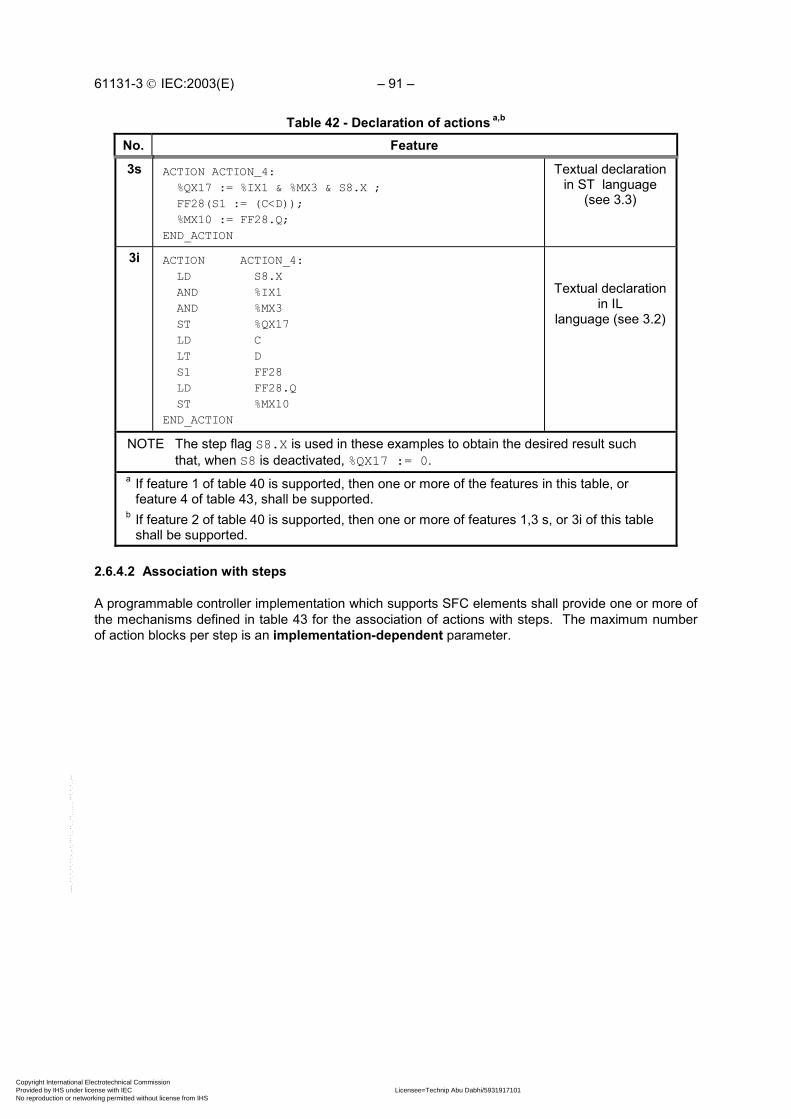
61131-3 IEC:2003(E) – 91 –
Table 42 - Declaration of actions a,b
No. Feature
3s ACTION ACTION_4: %QX17 := %IX1 & %MX3 & S8.X ; FF28(S1 := (C<D)); %MX10 := FF28.Q;END_ACTION
Textual declarationin ST language
(see 3.3)
3i ACTION ACTION_4: LD S8.X AND %IX1 AND %MX3 ST %QX17 LD C LT D S1 FF28 LD FF28.Q ST %MX10END_ACTION
Textual declarationin IL
language (see 3.2)
NOTE The step flag S8.X is used in these examples to obtain the desired result suchthat, when S8 is deactivated, %QX17 := 0.
a If feature 1 of table 40 is supported, then one or more of the features in this table, orfeature 4 of table 43, shall be supported.
b If feature 2 of table 40 is supported, then one or more of features 1,3 s, or 3i of this tableshall be supported.
2.6.4.2 Association with steps
A programmable controller implementation which supports SFC elements shall provide one or more ofthe mechanisms defined in table 43 for the association of actions with steps. The maximum numberof action blocks per step is an implementation-dependent parameter.
Copyright International Electrotechnical Commission Provided by IHS under license with IEC Licensee=Technip Abu Dabhi/5931917101
Not for Resale, 02/12/2006 07:01:30 MSTNo reproduction or networking permitted without license from IHS
--``,`,`,,,``````,,``,,``,,,,`,-`-`,,`,,`,`,,`---

– 92 – 61131-3 IEC:2003(E)
Table 43 - Step/action association
No. Example Feature
1
| +----+ +-----+----------+---+ | S8 |--| L | ACTION_1 |DN1|
+----+ |t#10s| | | | +-----+----------+---+ + DN1 |
Action blockphysically or
logicallyadjacent to the
step(see 2.6.4.3)
2
| +----+ +-----+---------------------+---+ | S8 |--| L | ACTION_1 |DN1| +----+ |t#10s| | | | +-----+---------------------+---+ +DN1 | P | ACTION_2 | | | +-----+---------------------+---+ | | N | ACTION_3 | | | +-----+---------------------+---+
Concatenatedaction blocksphysically or
logicallyadjacent to the
step
3STEP S8: ACTION_1(L,t#10s,DN1) ; ACTION_2(P) ; ACTION_3(N) ;END_STEP
Textualstep body
4 a
+-----+----------------------+---+ ----| N | ACTION_4 | |--- +-----+----------------------+---+ | %QX17 := %IX1 & %MX3 & S8.X ; | | FF28 (S1 := (C<D)); | | %MX10 := FF28.Q; | +--------------------------------+
Action block"d" field
(see 2.6.4.3)
a When feature 4 is used, the corresponding action name cannot be used in any otheraction block.
2.6.4.3 Action blocks
As shown in table 44, an action block is a graphical element for the combination of a Boolean variablewith one of the action qualifiers specified in subclause 2.6.4.4 to produce an enabling condition,according to the rules given in subclause 2.6.4.5, for an associated action.
The action block provides a means of optionally specifying Boolean “indicator” variables, indicated bythe “c” field in table 44, which can be set by the specified action to indicate its completion, timeout,error conditions, etc. If the “c” field is not present, and the “b” field specifies that the action shall be aBoolean variable, then this variable shall be interpreted as the “c” variable when required. If the (c)field is not defined, and the (b) field does not specify a Boolean variable, then the value of the“indicator” variable is considered to be always FALSE.
Copyright International Electrotechnical Commission Provided by IHS under license with IEC Licensee=Technip Abu Dabhi/5931917101
Not for Resale, 02/12/2006 07:01:30 MSTNo reproduction or networking permitted without license from IHS
--``,`,`,,,``````,,``,,``,,,,`,-`-`,,`,,`,`,,`---

61131-3 IEC:2003(E) – 93 –
When action blocks are concatenated graphically as illustrated in table 43, such concatenations canhave multiple indicator variables, but shall have only a single common Boolean input variable, whichshall act simultaneously upon all the concatenated blocks.
As well as being associated with a step, an action block can be used as a graphical element in the LDor FBD languages specified in clause 4. In this case, signal or power flow through an action blockshall follow the rules specified in 4.1.1.
Table 44 - Action block features
No. Feature Graphical form
1 a
23 b
4567
"a" : Qualifier as per 2.6.4.4"b" : Action name"c" : Boolean "indicator" variables
"d" : Action using: - IL language (3.2) - ST language (3.3) - LD language (4.2) - FBD language (4.3)
+-----+--------------+-----+---| "a" | "b" | "c" |---+-----+--------------+-----+| "d" || |+--------------------------+
No. Feature/Example
8 Use of action blocks in ladder diagrams (see 4.2):
| S8.X %IX7.5 +---+------+---+ OK1 |+--| |----| |----| N | ACT1 |DN1|--( )--+| +---+------+---+ |
9 Use of action blocks in function block diagrams (see 4.3):
+---+ +---+------+-----+ S8.X---| & |-----| N | ACT1 | DN1 |---OK1 %IX7.5---| | +---+------+-----+ +---+
a Field “a” can be omitted when the qualifier is “N”.b Field “c” can be omitted when no indicator variable is used.
2.6.4.4 Action qualifiers
Associated with each step/action association defined in 2.6.4.2, or each occurrence of an action blockas defined in 2.6.4.3, shall be an action qualifier. The value of this qualifier shall be one of the valueslisted in table 45. In addition, the qualifiers L, D, SD, DS, and SL shall have an associated duration oftype TIME.
NOTE IEC 60848 gives informal definitions and examples of the use of these qualifiers.This standard formalizes these definitions, redefining the S qualifier and introducingthe R qualifier. The control of actions using these qualifiers is defined in thefollowing subclause, and additional examples of their use are given in annex F.
Copyright International Electrotechnical Commission Provided by IHS under license with IEC Licensee=Technip Abu Dabhi/5931917101
Not for Resale, 02/12/2006 07:01:30 MSTNo reproduction or networking permitted without license from IHS
--``,`,`,,,``````,,``,,``,,,,`,-`-`,,`,,`,`,,`---

– 94 – 61131-3 IEC:2003(E)
Table 45 - Action qualifiers
No. Qualifier Explanation
1 None Non-stored (null qualifier)
2 N Non-stored
3 R overriding Reset
4 S Set (Stored)
5 L time Limited
6 D time Delayed
7 P Pulse
8 SD Stored and time Delayed
9 DS Delayed and Stored
10 SL Stored and time Limited
11 P1 Pulse (rising edge)
12 P0 Pulse (falling edge)
2.6.4.5 Action control
The control of actions shall be functionally equivalent to the application of the following rules:
1) Associated with each action shall be the functional equivalent of an instance of theACTION_CONTROL function block defined in figures 14 and 15. If the action is declared as aBoolean variable, as defined in 2.6.4.1, the Q output of this block shall be the state of thisBoolean variable. If the action is declared as a collection of statements or networks, as definedin 2.6.4.1, then this collection shall be executed continually while the A (activation) output of theACTION_CONTROL function block stands at BOOL#1. In this case, the state of the output Q(called the "action flag") can be accessed within the action by reading a read-only booleanvariable which has the form of a reference to the Q output of a function block instance whoseinstance name is the same as the corresponding action name, for example, ACTION1.Q.
NOTE 1 The condition Q=FALSE will ordinarily be used by an action to determine that it is beingexecuted for the final time during its current activation.
NOTE 2 The value of Q will always be FALSE during execution of actions invoked by P0 and P1qualifiers.
NOTE 3 The value of A will be TRUE for only one execution of an action invoked by a P1 or P0qualifier. For all other qualifiers, A will be true for one additional execution following thefalling edge of Q.
NOTE 4 Access to the functional equivalent of the Q or A outputs of an ACTION_CONTROL functionblock from outside of the associated action is an implementation-dependent feature.
NOTE 5 The manufacturer may opt for a simpler implementation as shown in figure 15 b). In thiscase, if the action is declared as a collection of statements or networks, as defined in 2.6.4.1,then this collection shall be executed continually while the Q output of the ACTION_CONTROLfunction block stands at BOOL#1. In any case the manufacturer shall specify which of thefeatures given in table 45 a) is supported.
Copyright International Electrotechnical Commission Provided by IHS under license with IEC Licensee=Technip Abu Dabhi/5931917101
Not for Resale, 02/12/2006 07:01:30 MSTNo reproduction or networking permitted without license from IHS
--``,`,`,,,``````,,``,,``,,,,`,-`-`,,`,,`,`,,`---

61131-3 IEC:2003(E) – 95 –
2) A Boolean input to the ACTION_CONTROL block for an action shall be said to have anassociation with a step as defined in 2.6.4.2, or with an action block as defined in 2.6.4.3, if thecorresponding qualifier is equivalent to the input name (N, R, S, L, D, P, P0, P1, SD,DS, or SL). The association shall be said to be active if the associated step is active, or if theassociated action block's input has the value BOOL#1. The active associations of an action areequivalent to the set of active associations of all inputs to its ACTION_CONTROL function block.
A Boolean input to an ACTION_CONTROL block shall have the value BOOL#1 if it has at least oneactive association, and the value BOOL#0 otherwise.
3) The value of the T input to an ACTION_CONTROL block shall be the value of the duration portionof a time-related qualifier (L, D, SD, DS, or SL) of an active association. If no such associationexists, the value of the T input shall be t#0s.
4) It shall be an error in the sense of subclause 1.5.1 if one or more of the following conditionsexist:
a) More than one active association of an action has a time-related qualifier (L, D, SD, DS,or SL).
b) The SD input to an ACTION_CONTROL block has the BOOL#1 when the Q1 output of itsSL_FF block has the value BOOL#1.
c) The SL input to an ACTION_CONTROL block has the value BOOL#1 when the Q1 output ofits SD_FF block has the value BOOL#1.
5) It is not required that the ACTION_CONTROL block itself be implemented, but only that thecontrol of actions be equivalent to the preceding rules. Only those portions of the action controlappropriate to a particular action need be instantiated, as illustrated in figure 16. In particular,note that simple MOVE (:=) and Boolean OR functions suffice for control of Boolean variableactions if the latter's associations have only “N” qualifiers.
a) b)
+----------------+ | ACTION_CONTROL |BOOL---|N Q|---BOOLBOOL---|R A|---BOOLBOOL---|S |BOOL---|L |BOOL---|D |BOOL---|P |BOOL---|P1 |BOOL---|P0 |BOOL---|SD |BOOL---|DS |BOOL---|SL |TIME---|T | +----------------+
+----------------+ | ACTION_CONTROL |BOOL---|N Q|---BOOLBOOL---|R |BOOL---|S |BOOL---|L |BOOL---|D |BOOL---|P |BOOL---|P1 |BOOL---|P0 |BOOL---|SD |BOOL---|DS |BOOL---|SL |TIME---|T | +----------------+
Figure 14 - ACTION_CONTROL function block - External interface (Not visible to the user) a) With “final scan” logic - see figure 15 a); b) Without “final scan” logic - see figure 15 b)
IEC 2485/02
Copyright International Electrotechnical Commission Provided by IHS under license with IEC Licensee=Technip Abu Dabhi/5931917101
Not for Resale, 02/12/2006 07:01:30 MSTNo reproduction or networking permitted without license from IHS
--``,`,`,,,``````,,``,,``,,,,`,-`-`,,`,,`,`,,`---

– 96 – 61131-3 IEC:2003(E)
+---+ +-----------------------------------------------------O| & |---Q | +-----+ | |N--|---------------------------------------------| >=1 |--| | | S_FF | | +---+R--+ +----+ | | | | RS | | | NOTE 1S--|----------------------|S Q1|-----------------| | Instances of this +----------------------|R1 | | | function block | +----+ +---+ | | are not visibleL--|---------+--------------------| & |----------| | to the user | | L_TMR +--O| | | | | | +-----+ | +---+ | | NOTE 2 | | | TON | | | | The external | +------|IN Q|---+ D_TMR | | interface of this | +-------------|PT | +-----+ | | function block type | | +-----+ | TON | | | is given in figureD--|--|-----------------------------|IN Q|------| | 14 a) | +-----------------------------|PT | | | | | P_TRIG +-----+ | | | | +--------+ | | | | | R_TRIG | | |P--|--|------------|CLK Q|--------------------| | | | SD_FF +--------+ SD_TMR | | | | +----+ +-----+ | | | | | RS | | TON | | |SD-|--|---|S Q1|----------------|IN Q|----------| | +--|---|R1 | +------------|PT | | | | | +----+ | DS_TMR +-----+ DS_FF | | | +------------+ +-----+ +----+ | | | | | TON | | RS | | |DS-|--|----------------|IN Q|----------|S Q1|---| | | +----------------|PT | +---|R1 | | | | | +-----+ | +----+ | | +--|-----------------------------+ | | | | SL_FF | | | | +----+ | | | | | RS | +---+ | |SL-|--|--------|S Q1|--+------------------| & |--| | +--|--------|R1 | | SL_TMR +--O| | +-----+ | +----+ | +-----+ | +---+ | | | TON | | | +----|IN Q|---+ +-----+T-----+---------------------|PT | +--------+ | >=1 | +-----+ | F_TRIG | Q---| |---A +--------+ Q---|CLK Q|---------| | | R_TRIG | +--------+ | |P1--------------|CLK Q|----------------------------------| | +--------+ +--------+ | | | F_TRIG | | |P0-----------------------------|CLK Q|-------------------| | +--------+ +-----+
Figure 15 a) - ACTION_CONTROL function block body with “final scan” logicIEC 2486/02
Copyright International Electrotechnical Commission Provided by IHS under license with IEC Licensee=Technip Abu Dabhi/5931917101
Not for Resale, 02/12/2006 07:01:30 MSTNo reproduction or networking permitted without license from IHS
--``,`,`,,,``````,,``,,``,,,,`,-`-`,,`,,`,`,,`---

61131-3 IEC:2003(E) – 97 –
+---+ +-----------------------------------------------------O| & |---Q | +-----+ | |N--|---------------------------------------------| >=1 |--| | | S_FF | | +---+R--+ +----+ | | | | RS | | | NOTE 1 -S--|----------------------|S Q1|-----------------| | instances of this +----------------------|R1 | | | function block | +----+ +---+ | | are not visibleL--|---------+--------------------| & |----------| | to the user | | L_TMR +--O| | | | | | +-----+ | +---+ | | NOTE 2 - | | | TON | | | | The external | +------|IN Q|---+ D_TMR | | interface of this | +-------------|PT | +-----+ | | function block type | | +-----+ | TON | | | is given in figureD--|--|-----------------------------|IN Q|------| | 14 b) | +-----------------------------|PT | | | | | P_TRIG +-----+ | | | | +--------+ | | | | | R_TRIG | | |P--|--|------------|CLK Q|--------------------| | | | SD_FF +--------+ SD_TMR | | | | +----+ +-----+ | | | | | RS | | TON | | |SD-|--|---|S Q1|----------------|IN Q|----------| | +--|---|R1 | +------------|PT | | | | | +----+ | DS_TMR +-----+ DS_FF | | | +------------+ +-----+ +----+ | | | | | TON | | RS | | |DS-|--|----------------|IN Q|----------|S Q1|---| | | +----------------|PT | +---|R1 | | | | | +-----+ | +----+ | | +--|-----------------------------+ | | | | SL_FF | | | | +----+ | | | | | RS | +---+ | |SL-|--|--------|S Q1|--+------------------| & |--| | +--|--------|R1 | | SL_TMR +--O| | | | | +----+ | +-----+ | +---+ | | | | | TON | | | | | +----|IN Q|---+ | |T-----+---------------------|PT | | | +--------+ +-----+ | | | R_TRIG | | |P1--------|CLK Q|-----------------------------| | +--------+ +--------+ | | | F_TRIG | | |P0-----------------------|CLK Q|--------------| | +--------+ +-----+
Figure 15 b) - ACTION_CONTROL function block body without “final scan” logicIEC 2487/02
Copyright International Electrotechnical Commission Provided by IHS under license with IEC Licensee=Technip Abu Dabhi/5931917101
Not for Resale, 02/12/2006 07:01:30 MSTNo reproduction or networking permitted without license from IHS
--``,`,`,,,``````,,``,,``,,,,`,-`-`,,`,,`,`,,`---

– 98 – 61131-3 IEC:2003(E)
| +-----+ +---+------------+----------------+ | S22 |---| N | HV_BREAKER | HV_BRKR_CLOSED | +-----+ +---+------------+----------------+ | | S | START_INDICATOR | | +---+-----------------------------+ + HV_BRKR_CLOSED | +-----+ +----+---------------+ | S23 |---| SL | RUNUP_MONITOR | +-----+ |t#1m| | | +----+---------------+ | | D | START_WAIT | | |t#1s| | | +----+---------------+ + START_WAIT | +-----+ +-----+-----------------+------------------+ | S24 |---| N | ADVANCE_STARTER | STARTER_ADVANCED | +-----+ +-----+-----------------+------------------+ | | L | START_MONITOR | | |t#30s| | | +-----+------------------------------------+ + STARTER_ADVANCED | +-----+ +-----+-----------------+-------------------+ | S26 |---| N | RETRACT_STARTER | STARTER_RETRACTED | +-----+ +-----+-----------------+-------------------+ | | + STARTER_RETRACTED | +-----+ +-----+-----------------+ | S27 |---| R | START_INDICATOR | +-----+ +-----+-----------------+ | | R | RUNUP_MONITOR | | +-----+-----------------+
NOTE The complete SFC network and its associated declarations are not shown in this example.
Figure 16 a) - Action control example - SFC representation
Table 45 a) - Action control features
No. Description
1 per figures 14 a) and 15 a)
2 per figures 14 b) and 15 b)
IEC 2488/02
Copyright International Electrotechnical Commission Provided by IHS under license with IEC Licensee=Technip Abu Dabhi/5931917101
Not for Resale, 02/12/2006 07:01:30 MSTNo reproduction or networking permitted without license from IHS
--``,`,`,,,``````,,``,,``,,,,`,-`-`,,`,,`,`,,`---

61131-3 IEC:2003(E) – 99 –
S22.X---------------------------------------------------HV_BREAKER
S24.X----------------------------------------------ADVANCE_STARTER
S26.X----------------------------------------------RETRACT_STARTER
START_INDICATOR_S_FF +----+ | RS |S22.X-----------------------|S Q1|-----------------START_INDICATORS27.X-----------------------|R1 | +----+
START_WAIT_D_TMR +-----+ | TON |S23.X-----------------------|IN Q|---------------------START_WAITt#1s------------------------|PT | +-----+
RUNUP_MONITOR_SL_FF +----+ | RS | +---+S23.X---|S Q1|--+-----------------------------| & |--RUNUP_MONITORS27.X---|R1 | | RUNUP_MONITOR_SL_TMR +--O| | +----+ | +-----+ | +---+ | | TON | | +---------|IN Q|---------+t#1m----------------------|PT | +-----+
+---+S24.X------------+---------------------------| & |---START_MONITOR | START_MONITOR_L_TMR +---O| | | +-----+ | +---+ | | TON | | +--------|IN Q|-------+t#30s---------------------|PT | +-----+
Figure 16 b) - Action control example - functional equivalent
2.6.5 Rules of evolution
The initial situation of a SFC network is characterized by the initial step which is in the active stateupon initialization of the program or function block containing the network.
Evolutions of the active states of steps shall take place along the directed links when caused by theclearing of one or more transitions.
A transition is enabled when all the preceding steps, connected to the corresponding transition symbolby directed links, are active. The clearing of a transition occurs when the transition is enabled andwhen the associated transition condition is true.
The clearing of a transition causes the deactivation (or "resetting") of all the immediately precedingsteps connected to the corresponding transition symbol by directed links, followed by the activation ofall the immediately following steps.
IEC 2489/02
Copyright International Electrotechnical Commission Provided by IHS under license with IEC Licensee=Technip Abu Dabhi/5931917101
Not for Resale, 02/12/2006 07:01:30 MSTNo reproduction or networking permitted without license from IHS
--``,`,`,,,``````,,``,,``,,,,`,-`-`,,`,,`,`,,`---

– 100 – 61131-3 IEC:2003(E)
The alternation step/transition and transition/step shall always be maintained in SFC elementconnections, that is:
- Two steps shall never be directly linked; they shall always be separated by a transition.
- Two transitions shall never be directly linked; they shall always be separated by a step.
When the clearing of a transition leads to the activation of several steps at the same time, thesequences to which these steps belong are called simultaneous sequences. After their simultaneousactivation, the evolution of each of these sequences becomes independent. In order to emphasize thespecial nature of such constructs, the divergence and convergence of simultaneous sequences shallbe indicated by a double horizontal line.
It shall be an error if the possibility can arise that non-prioritized transitions in a selection divergence,as shown in feature 2a of table 46, are simultaneously true. The user may make provisions to avoidthis error as shown in features 2b and 2c of table 46.
Table 46 defines the syntax and semantics of the allowed combinations of steps and transitions.
The clearing time of a transition may theoretically be considered as short as one may wish, but it cannever be zero. In practice, the clearing time will be imposed by the programmable controllerimplementation. For the same reason, the duration of a step activity can never be considered to bezero.
Several transitions which can be cleared simultaneously shall be cleared simultaneously, within thetiming constraints of the particular programmable controller implementation and the priority constraintsdefined in table 46.
Testing of the successor transition condition(s) of an active step shall not be performed until theeffects of the step activation have propagated throughout the program organization unit in which thestep is declared.
Figure 17 illustrates the application of these rules. In this figure, the active state of a step is indicatedby the presence of an asterisk (*) in the corresponding block. This notation is used for illustration only,and is not a required language feature.
The application of the rules given in this subclause cannot prevent the formulation of “unsafe” SFCs,such as the one shown in figure 18 a), which may exhibit uncontrolled proliferation of tokens.Likewise, the application of these rules cannot prevent the formulation of “unreachable” SFCs, such asthe one shown in figure 18 b), which may exhibit “locked up” behavior. The programmable controllersystem shall treat the existence of such conditions as errors as defined in 1.5.1.
The maximum allowed widths of the “divergence” and “convergence” constructs in table 46 areimplementation-dependent parameters.
Copyright International Electrotechnical Commission Provided by IHS under license with IEC Licensee=Technip Abu Dabhi/5931917101
Not for Resale, 02/12/2006 07:01:30 MSTNo reproduction or networking permitted without license from IHS
--``,`,`,,,``````,,``,,``,,,,`,-`-`,,`,,`,`,,`---

61131-3 IEC:2003(E) – 101 –
Table 46 - Sequence evolutionNo. Example Rule
1 |+----+| S3 |+----+| + c|+----+| S4 |+----+|
Single sequence:The alternation step-transition is repeated in
series.Example:
An evolution from step S3 to step S4 shall takeplace if and only if step S3 is in the active state
and the transition condition c is true.
2a |+----+| S5 | +----+| +-----*----+--...| | + e + f| |+----+ +----+| S6 | | S8 |+----+ +----+| |
Divergence of sequence selection:A selection between several sequences is
represented by as many transition symbols, underthe horizontal line, as there are different possible
evolutions. The asterisk denotes left-to-rightpriority of transition evaluations.
Example:An evolution shall take place from S5 to S6 only ifS5 is active and the transition condition e is true,or from S5 to S8 only if S5 is active and f is true
and e is false.
2b | +----+ | S5 | +----+ | +-----*-----+--... |2 |1 + e + f | | +----+ +----+ | S6 | | S8 | +----+ +----+ | |
Divergence of sequence selection:The asterisk, followed by numbered branches,
indicates a user-defined priority of transitionevaluation, with the lowest-numbered branch
having the highest priority.Example:
An evolution shall take place from S5 to S8 only ifS5 is active and the transition condition f is true,or from S5 to S6 only if S5 is active, and e is true,
and f is false.
2c | +----+ | S5 | +----+ | +------+----+--...| | +e +NOT e & f| |+----+ +----+| S6 | | S8 |+----+ +----+| |
Divergence of sequence selection:The connection of the branch indicates that theuser must assure that transition conditions aremutually exclusive, as specified by IEC 60848.
Example:An evolution shall take place from S5 to S6 only ifS5 is active and the transition condition e is true,or from S5 to S8 only if S5 is active and e is false
and f is true.
Copyright International Electrotechnical Commission Provided by IHS under license with IEC Licensee=Technip Abu Dabhi/5931917101
Not for Resale, 02/12/2006 07:01:30 MSTNo reproduction or networking permitted without license from IHS
--``,`,`,,,``````,,``,,``,,,,`,-`-`,,`,,`,`,,`---

– 102 – 61131-3 IEC:2003(E)
Table 46 - Sequence evolutionNo. Example Rule
3 | |+----+ +----+| S7 | | S9 |+----+ +----+| | + h + j| | +-----+-----+--...|+----+|S10 |+----+|
Convergence of sequence selection:The end of a sequence selection isrepresented by as many transition
symbols, above the horizontal line, as there areselection paths to be ended.
Example:An evolution shall take place
from S7 to S10 only if S7 is active and thetransition condition h is true, or from S9 to S10
only if S9 is active and j is true.
4 |+----+|S11 |+----+| + b| ==+=====+=====+==...| |+----+ +----+| S12| | S14|+----+ +----+| |
Simultaneous sequences - divergence:Only one common transition symbol shall bepossible, above the double horizontal line of
synchronization.Example:
An evolution shall take place from S11 to S12,S14,... only if S11 is active and the transition
condition “b” associated to the common transitionis true. After the simultaneous activation of S12,
S14, etc., the evolution of each sequenceproceeds independently.
| |+----+ +----+| S13| | S15|+----+ +----+| | ==+=====+=====+==...| + d|+----+|S16 |+----+|
Simultaneous sequences - convergence:Only one common transition symbol shall bepossible, under the double horizontal line of
synchronization.Example:
An evolution shall take place from S13, S15,... toS16 only if all steps above and connected to the
double horizontal line are active and the transitioncondition “d” associated to the common transition
is true.
Copyright International Electrotechnical Commission Provided by IHS under license with IEC Licensee=Technip Abu Dabhi/5931917101
Not for Resale, 02/12/2006 07:01:30 MSTNo reproduction or networking permitted without license from IHS
--``,`,`,,,``````,,``,,``,,,,`,-`-`,,`,,`,`,,`---

61131-3 IEC:2003(E) – 103 –
Table 46 - Sequence evolutionNo. Example Rule
5a5b5c
| +-----+ | S30 | +-----+ | +---*---+ | | + a +d | |+-----+ || S31 | |+-----+ | | | + b | | |+-----+ || S32 | |+-----+ | | | + c | | | +---+---+ | +-----+ | S33 | +-----+ |
Sequence skip:A “sequence skip” is a special case of
sequence selection (feature 2) in which one ormore of the branches contain no steps. features5a, 5b, and 5c correspond to the representation
options given in features 2a, 2b, and 2c,respectively.Example:
(feature 5a shown)An evolution shall take place from S30 to S33 if“a” is false and “d” is true, that is, the sequence
(S31, S32) will be skipped.
6a6b6c
|+-----+| S30 |+-----+| + a| +---------+ | | +-----+ | | S31 | | +-----+ | | | + b | | | +-----+ | | S32 | | +-----+ | | | *-----+ | | | | + c + d | | | | +-----+ +---+| S33 |+-----+|
Sequence loop:A “sequence loop” is a special case of sequenceselection (feature 2) in which one or more of thebranches returns to a preceding step. Features6a, 6b, and 6c correspond to the representation
options given in features 2a, 2b, and 2c,respectively.Example:
(feature 6a shown)An evolution shall take place from S32 to S31 if“c” is false and “d” is true, that is, the sequence
(S31, S32) will be repeated.
Copyright International Electrotechnical Commission Provided by IHS under license with IEC Licensee=Technip Abu Dabhi/5931917101
Not for Resale, 02/12/2006 07:01:30 MSTNo reproduction or networking permitted without license from IHS
--``,`,`,,,``````,,``,,``,,,,`,-`-`,,`,,`,`,,`---

– 104 – 61131-3 IEC:2003(E)
Table 46 - Sequence evolutionNo. Example Rule
7 |+-----+| S30 |+-----+| + a| +----<----+ | | +-----+ | | S31 | | +-----+ | | | + b | | | +-----+ | | S32 | | +-----+ | | | *-----+ | | | | + c + d | | | | +-----+ +->-+| S33 |+-----+|
Directional arrows:When necessary for clarity, the “less than” (<)
character of the character set defined in 2.1.1 canbe used to indicate right-to-left control flow, andthe “greater than” (>) character to represent left-to-right control flow. When this feature is used,
the corresponding character shall be locatedbetween two “-” characters, that is, in the
character sequence “-<-” or “->-” as shown in theaccompanying example.
Copyright International Electrotechnical Commission Provided by IHS under license with IEC Licensee=Technip Abu Dabhi/5931917101
Not for Resale, 02/12/2006 07:01:30 MSTNo reproduction or networking permitted without license from IHS
--``,`,`,,,``````,,``,,``,,,,`,-`-`,,`,,`,`,,`---

61131-3 IEC:2003(E) – 105 –
a) Transition notenabled
(X = 0 or 1)
| | | |+------+ +-----+ +------+ +------+|STEP10| |STEP9| |STEP13| |STEP22|| | | | | * | | * |+------+ +-----+ +------+ +------+ | | | | + X ====+========+=========+==== | |+------+ + X|STEP11| || | ====+====+===+====+------+ | | | +------+ +------+ |STEP15| |STEP16| | | | | +------+ +------+ | |
b) Transition enabledbut not cleared(X = 0 )
| | | |+------+ +-----+ +------+ +------+|STEP10| |STEP9| |STEP13| |STEP22|| * | | * | | * | | * |+------+ +-----+ +------+ +------+ | | | | + X ===+========+=========+==== | |+------+ + X|STEP11| || | ====+====+====+====+------+ | | | +------+ +------+ |STEP15| |STEP16| | | | | +------+ +------+ | |
c) Transitioncleared
(X = 1 )
| | | |+------+ +-----+ +------+ +------+|STEP10| |STEP9| |STEP13| |STEP22|| | | | | | | |+------+ +-----+ +------+ +------+ | | | | + X ====+========+=========+==== | |+------+ + X|STEP11| || * | ====+====+===+====+------+ | | | +------+ +------+ |STEP15| |STEP16| | * | | * | +------+ +------+ | |
NOTE In this figure, the active state of a step is indicated by the presence of an asterisk (*) inthe corresponding block. This notation is used for illustration only, and is not a requiredlanguage feature.
Figure 17 - Examples of SFC evolution rules
IEC 2490/02
Copyright International Electrotechnical Commission Provided by IHS under license with IEC Licensee=Technip Abu Dabhi/5931917101
Not for Resale, 02/12/2006 07:01:30 MSTNo reproduction or networking permitted without license from IHS
--``,`,`,,,``````,,``,,``,,,,`,-`-`,,`,,`,`,,`---

– 106 – 61131-3 IEC:2003(E)
+----------------------+| || +=====+| || A ||| +=====+| || + t1| || ======+==========+============+=======| | || +-----+ +-----+| | B | | C || +-----+ +-----+| | || | *--------+| | | || | + t2 + t3| | | || | +---+ +---+| | | D | | E || | +---+ +---+| | | || ===+==========+============+=== || | || + t4 + t5| | || +---+ +---+| | F | | G || +---+ +---+| | || + t6 + t7| | |+----------------------+---------------------+
Figure 18 a) - Examples of SFC errors: an “unsafe” SFC(see 2.6.5)
IEC 2491/02
Copyright International Electrotechnical Commission Provided by IHS under license with IEC Licensee=Technip Abu Dabhi/5931917101
Not for Resale, 02/12/2006 07:01:30 MSTNo reproduction or networking permitted without license from IHS
--``,`,`,,,``````,,``,,``,,,,`,-`-`,,`,,`,`,,`---

61131-3 IEC:2003(E) – 107 –
+----------------------+| || +=====+| || A ||| +=====+| || + t1| || ======+==========+============+=======| | || +-----+ +-----+| | B | | C || +-----+ +-----+| | || | *--------+| | | || | + t2 + t3| | | || | +---+ +---+| | | D | | E || | +---+ +---+| | | || ===+==========+============+=== || | || + t4 + t5| | || +---+ +---+| | F | | G || +---+ +---+| | || ====+==========+==========+===| || + t6| |+---------------------------------+
Figure 18 b) - Examples of SFC errors: an “unreachable” SFC(see 2.6.5)
2.6.6 Compatibility of SFC elements
SFCs can be represented graphically or textually, utilizing the elements defined above. Table 47summarizes for convenience those elements which are mutually compatible for graphical and textualrepresentation, respectively.
IEC 2492/02
Copyright International Electrotechnical Commission Provided by IHS under license with IEC Licensee=Technip Abu Dabhi/5931917101
Not for Resale, 02/12/2006 07:01:30 MSTNo reproduction or networking permitted without license from IHS
--``,`,`,,,``````,,``,,``,,,,`,-`-`,,`,,`,`,,`---

– 108 – 61131-3 IEC:2003(E)
Table 47 - Compatible SFC features
Table Graphical representation Textual representation
40 1, 3a, 3b, 4 2, 3a, 4
41 1, 2, 3, 4, 4a, 4b, 7, 7a, 7b 5, 6, 7c, 7d
42 1, 2l, 2s, 2f 3s, 3i
43 1, 2, 4 3
44 1 to 9 --
45 1 to 10 1 to 10 (textual equivalent)
46 1 to 7 1 to 6
57 All --
2.6.7 SFC Compliance requirements
In order to claim compliance with the requirements of 2.6, the elements shown in table 48 shall besupported and the compatibility requirements defined in 2.6.6 shall be observed.
Table 48 - SFC minimal compliance requirements
Table Graphical representation Textual representation
40 1 2
41 1 or 2 or 3 or (4 and (4a or 4b)) or (7 and (7a or 7b or 7c or 7d))
5 or 6
42 1 or 2l or 2f 1 or 3s or 3i
43 1 or 2 or 4 3
45 1 or 2 1 or 2
46 1 and (2a or 2b or 2c) and 3 and 4 Same (textual equivalent)
57 (1 or 2) and (3 or 4) and (5 or 6) and(7 or 8) and (9 or 10) and (11 or 12)
Not required
2.7 Configuration elements
As described in 1.4.1, a configuration consists of resources, tasks (which are defined withinresources), global variables, access paths and instance specific initializations. Each of theseelements is defined in detail in this subclause.
A graphic example of a simple configuration is shown in figure 19 a). Skeleton declarations for thecorresponding function blocks and programs are given in figure 19 b). This figure serves as areference point for the examples of configuration elements given in the remainder of this subclausesuch as in figure 20.
Copyright International Electrotechnical Commission Provided by IHS under license with IEC Licensee=Technip Abu Dabhi/5931917101
Not for Resale, 02/12/2006 07:01:30 MSTNo reproduction or networking permitted without license from IHS
--``,`,`,,,``````,,``,,``,,,,`,-`-`,,`,,`,`,,`---

61131-3 IEC:2003(E) – 109 –
CONFIGURATION CELL_1RESOURCE STATION_1
F G
B
RESOURCE STATION_2
C D
GLOBAL AND DIRECTLY REPRESENTED VARIABLESAND INSTANCE-SPECIFIC INITIALIZATIONS
ACCESS PATHS
TASKSLOW_1
P1 P2 P1 P4
x1 y1y2
FB2
FB1 FB2
z1
x2
FAST_1SLOW_1
BAKER ABLE CHARLIE DOG GAMMA ALPHA BETA
x1x2
PER_2
F H
HOUT1
INT_2
b1b2
d1
Communication function (See IEC 1131-5)
PER_2COUNT
S1_COUNT
THETA
C2C3
TASKFAST_1
TASKPER_2
TASKINT_2
%IX1.1
A y1
FB1
y2
SLOW_1
out1
w z2 %QW5
ZETA
%QB25
c1
OMEGA
Figure 19 a) - Graphical example of a configuration
IEC 2493/02
Copyright International Electrotechnical Commission Provided by IHS under license with IEC Licensee=Technip Abu Dabhi/5931917101
Not for Resale, 02/12/2006 07:01:30 MSTNo reproduction or networking permitted without license from IHS
--``,`,`,,,``````,,``,,``,,,,`,-`-`,,`,,`,`,,`---

– 110 – 61131-3 IEC:2003(E)
FUNCTION_BLOCK A VAR_OUTPUT y1 : UINT ; y2 : BYTE ; END_VAREND_FUNCTION_BLOCK
FUNCTION_BLOCK B VAR_INPUT b1 : UINT ; b2 : BYTE ; END_VAREND_FUNCTION_BLOCK
FUNCTION_BLOCK C VAR_OUTPUT c1 : BOOL ; END_VAR VAR C2 AT %Q*: BYTE; C3: INT; END_VAREND_FUNCTION_BLOCK
FUNCTION_BLOCK D VAR_INPUT d1 : BOOL ; END_VAR VAR_OUTPUT y2 : INT ; END_VAREND_FUNCTION_BLOCK
PROGRAM F VAR_INPUT x1 : BOOL ; x2 : UINT ; END_VAR VAR_OUTPUT y1 : BYTE ; END_VAR VAR COUNT: INT; TIME1: TON; END_VAR END_PROGRAM
PROGRAM G VAR_OUTPUT out1 : UINT ; END_VAR VAR_EXTERNAL z1 : BYTE ; END_VAR VAR FB1 : A ; FB2 : B ; END_VAR FB1(...); out1 := FB1.y1; z1 := FB1.y2; FB2(b1 := FB1.y1, b2 := FB1.y2) ; END_PROGRAM
PROGRAM H VAR_OUTPUT HOUT1: INT ; END_VAR VAR FB1 : C ; FB2 : D ; END_VAR FB1(...) ; FB2(...); HOUT1 := FB2.y2; END_PROGRAM
Figure 19 b) - Skeleton function block and program declarations for configuration example
2.7.1 Configurations, resources, and access paths
Table 49 enumerates the language features for declaration of configurations, resources, globalvariables, access paths and instance specific initializations. Partial enumeration of TASK declarationfeatures is also given; additional information on tasks is provided in 2.7.2. The formal syntax for thesefeatures is given in B.1.7. Figure 20 provides examples of these features, corresponding to theexample configuration shown in figure 19 a) and the supporting declarations in figure 19 b).
The ON qualifier in the RESOURCE...ON...END_RESOURCE construction is used to specify the type of“processing function” and its “man-machine interface” and “sensor and actuator interface” functionsupon which the resource and its associated programs and tasks are to be implemented. Themanufacturer shall supply an implementation-dependent resource library of such functions, asillustrated in figure 3. Associated with each element in this library shall be an identifier (the resourcetype name) for use in resource declaration.
NOTE The RESOURCE...ON...END_RESOURCE construction is not required in a configurationwith a single resource. See the production single_resource_declaration in B.1.7for the syntax to be used in this case.
IEC 2494/02
Copyright International Electrotechnical Commission Provided by IHS under license with IEC Licensee=Technip Abu Dabhi/5931917101
Not for Resale, 02/12/2006 07:01:30 MSTNo reproduction or networking permitted without license from IHS
--``,`,`,,,``````,,``,,``,,,,`,-`-`,,`,,`,`,,`---

61131-3 IEC:2003(E) – 111 –
The scope of a VAR_GLOBAL declaration shall be limited to the configuration or resource in which it isdeclared, with the exception that an access path can be declared to a global variable in a resourceusing feature 10d in table 49.
The VAR_ACCESS...END_VAR construction provides a means of specifying variable names whichcan be used for remote access by some of the communication services specified in IEC 61131-5. Anaccess path associates each such variable name with a global variable, a directly represented variableas defined in 2.4.1.1, or any input, output, or internal variable of a program or function block.
The association shall be accomplished by qualifying the name of the variable with the completehierarchical concatenation of instance names, beginning with the name of the resource (if any),followed by the name of the program instance (if any), followed by the name(s) of the function blockinstance(s) (if any). The name of the variable is concatenated at the end of the chain. All names in theconcatenation shall be separated by dots. If such a variable is a multi-element variable (structure orarray), an access path can also be specified to an element of the variable.
It shall not be possible to define access paths to variables that are declared in VAR_TEMP,VAR_EXTERNAL or VAR_IN_OUT declarations.
The direction of the access path can be specified as READ_WRITE or READ_ONLY, indicating that thecommunication services can both read and modify the value of the variable in the first case, or readbut not modify the value in the second case. If no direction is specified, the default direction isREAD_ONLY.
Access to variables that are declared CONSTANT or to function block inputs that are externallyconnected to other variables shall be READ_ONLY.
NOTE The effect of using READ_WRITE access to function block output variables isimplementation-dependent.
The VAR_CONFIG...END_VAR construction provides a means to assign instance specific locations tosymbolically represented variables, which are nominated for the respective purpose by using theasterisk notation described in 2.4.1.1 and 2.4.3.1, respectively, or to assign instance specific initialvalues to symbolically represented variables, or both.
The assignment shall be accomplished by qualifying the name of the object to be located or initializedwith the complete hierarchical concatenation of instance names, beginning with the name of theresource (if any), followed by the name of the program instance, followed by the name(s) of thefunction block instance(s) (if any). The name of the object to be located or initialized is concatenatedat the end of the chain. All names in the concatenation shall be separated by dots. The locationassignment or the initial value assignment follows the syntax and the semantics described in 2.4.3.1and 2.4.3.2 respectively.
Instance specific initial values provided by the VAR_CONFIG...END_VAR construction alwaysoverride type specific initial values. It shall not be possible to define instance specific initializations tovariables which are declared in VAR_TEMP, VAR_EXTERNAL, VAR CONSTANT or VAR_IN_OUTdeclarations.
Copyright International Electrotechnical Commission Provided by IHS under license with IEC Licensee=Technip Abu Dabhi/5931917101
Not for Resale, 02/12/2006 07:01:30 MSTNo reproduction or networking permitted without license from IHS
--``,`,`,,,``````,,``,,``,,,,`,-`-`,,`,,`,`,,`---

– 112 – 61131-3 IEC:2003(E)
Table 49 - Configuration and resource declaration featuresNo. Description
1 CONFIGURATION...END_CONFIGURATION construction2 VAR_GLOBAL...END_VAR construction within CONFIGURATION3 RESOURCE...ON...END_RESOURCE construction4 VAR_GLOBAL...END_VAR construction within RESOURCE5a Periodic TASK construction (see note 1)5b Non-periodic TASK construction (see note 1)6a WITH construction for PROGRAM to TASK association (see note 1)6b WITH construction for Function Block to TASK association (see note 1)6c PROGRAM declaration with no TASK association (see note 1)7 Declaration of directly represented variables in VAR_GLOBAL (see note 2)8a Connection of directly represented variables to PROGRAM inputs8b Connection of GLOBAL variables to PROGRAM inputs9a Connection of PROGRAM outputs to directly represented variables9b Connection of PROGRAM outputs to GLOBAL variables10a VAR_ACCESS...END_VAR construction10b Access paths to directly represented variables10c Access paths to PROGRAM inputs10d Access paths to GLOBAL variables in RESOURCEs10e Access paths to GLOBAL variables in CONFIGURATIONs10f Access paths to PROGRAM outputs10g Access paths to PROGRAM internal variables10h Access paths to function block inputs10i Access paths to function block outputs11 VAR_CONFIG...END_VAR constructiona
12a VAR_GLOBAL CONSTANT in RESOURCE declarations12b VAR_GLOBAL CONSTANT in CONFIGURATION declarations13a VAR_EXTERNAL in RESOURCE declarations13b VAR_EXTERNAL CONSTANT in RESOURCE declarations
NOTE 1 See 2.7.2 for further descriptions of TASK features.NOTE 2 See 2.4.3.1 for further descriptions of related features.a This feature shall be supported if feature 10 in table 15 is supported.
Copyright International Electrotechnical Commission Provided by IHS under license with IEC Licensee=Technip Abu Dabhi/5931917101
Not for Resale, 02/12/2006 07:01:30 MSTNo reproduction or networking permitted without license from IHS
--``,`,`,,,``````,,``,,``,,,,`,-`-`,,`,,`,`,,`---

61131-3 IEC:2003(E) – 113 –
Figure 20 - Examples of CONFIGURATION and RESOURCE declaration features
No. Example
1 CONFIGURATION CELL_1
2 VAR_GLOBAL w: UINT; END_VAR
3 RESOURCE STATION_1 ON PROCESSOR_TYPE_1
4 VAR_GLOBAL z1: BYTE; END_VAR
5a TASK SLOW_1(INTERVAL := t#20ms, PRIORITY := 2) ;
5a TASK FAST_1(INTERVAL := t#10ms, PRIORITY := 1) ;
6a8a
PROGRAM P1 WITH SLOW_1 :
F(x1 := %IX1.1) ;
9b PROGRAM P2 : G(OUT1 => w,
6b FB1 WITH SLOW_1,
6b FB2 WITH FAST_1) ;
3 END_RESOURCE
3 RESOURCE STATION_2 ON PROCESSOR_TYPE_2
4 VAR_GLOBAL z2 : BOOL ;
7 AT %QW5 : INT ;
4 END_VAR
5a TASK PER_2(INTERVAL := t#50ms, PRIORITY := 2) ;
5b TASK INT_2(SINGLE := z2, PRIORITY := 1) ;
6a8b
PROGRAM P1 WITH PER_2 :
F(x1 := z2, x2 := w) ;
6a9a
PROGRAM P4 WITH INT_2 :
H(HOUT1 => %QW5,
6b FB1 WITH PER_2);
3 END_RESOURCE
10a VAR_ACCESS
10b ABLE : STATION_1.%IX1.1 : BOOL READ_ONLY ;
10c BAKER : STATION_1.P1.x2 : UINT READ_WRITE ;
10d CHARLIE : STATION_1.z1 : BYTE ;
10e DOG : w : UINT READ_ONLY ;
10f ALPHA : STATION_2.P1.y1 : BYTE READ_ONLY ;
10f BETA : STATION_2.P4.HOUT1 : INT READ_ONLY ;
10d GAMMA : STATION_2.z2 : BOOL READ_WRITE ;
10g S1_COUNT : STATION_1.P1.COUNT : INT;
10h THETA : STATION_2.P4.FB2.d1 : BOOL READ_WRITE;
10i ZETA : STATION_2.P4.FB1.c1 : BOOL READ_ONLY;
10k OMEGA : STATION_2.P4.FB1.C3 : INT READ_WRITE;
Copyright International Electrotechnical Commission Provided by IHS under license with IEC Licensee=Technip Abu Dabhi/5931917101
Not for Resale, 02/12/2006 07:01:30 MSTNo reproduction or networking permitted without license from IHS
--``,`,`,,,``````,,``,,``,,,,`,-`-`,,`,,`,`,,`---

– 114 – 61131-3 IEC:2003(E)
Figure 20 - Examples of CONFIGURATION and RESOURCE declaration features
No. Example
10a END_VAR
11 VAR_CONFIG STATION_1.P1.COUNT : INT := 1; STATION_2.P1.COUNT : INT := 100; STATION_1.P1.TIME1 : TON := (PT := T#2.5s); STATION_2.P1.TIME1 : TON := (PT := T#4.5s); STATION_2.P4.FB1.C2 AT %QB25 : BYTE; END_VAR
1 END_CONFIGURATION
NOTE 1 Graphical and semigraphic representation of these features is allowed but isbeyond the scope of this part of IEC 61131.
NOTE 2 It is an error if the data type declared for a variable in a VAR_ACCESSstatement is not the same as the data type declared for the variable elsewhere,e.g., if variable BAKER is declared of type WORD in the above examples.
2.7.2 Tasks
For the purposes of this part of IEC 61131, a task is defined as an execution control element which iscapable of invoking, either on a periodic basis or upon the occurrence of the rising edge of a specifiedBoolean variable, the execution of a set of program organization units, which can include programsand function blocks whose instances are specified in the declaration of programs.
The maximum number of tasks per resource and task interval resolution are implementation-dependent parameters.
Tasks and their association with program organization units can be represented graphically ortextually using the WITH construction, as shown in table 50, as part of resources within configurations.A task is implicitly enabled or disabled by its associated resource according to the mechanismsdefined in 1.4.1. The control of program organization units by enabled tasks shall conform to thefollowing rules:
1) The associated program organization units shall be scheduled for execution upon each rising edgeof the SINGLE input of the task.
2) If the INTERVAL input is non-zero, the associated program organization units shall be scheduledfor execution periodically at the specified interval as long as the SINGLE input stands at zero (0). Ifthe INTERVAL input is zero (the default value), no periodic scheduling of the associated programorganization units shall occur.
3) The PRIORITY input of a task establishes the scheduling priority of the associated programorganization units, with zero (0) being highest priority and successively lower priorities havingsuccessively higher numeric values. As shown in table 50, the priority of a program organizationunit (that is, the priority of its associated task) can be used for preemptive or non-preemptivescheduling.
IEC 2495/02
Copyright International Electrotechnical Commission Provided by IHS under license with IEC Licensee=Technip Abu Dabhi/5931917101
Not for Resale, 02/12/2006 07:01:30 MSTNo reproduction or networking permitted without license from IHS
--``,`,`,,,``````,,``,,``,,,,`,-`-`,,`,,`,`,,`---

61131-3 IEC:2003(E) – 115 –
a) In non-preemptive scheduling, processing power becomes available on a resource whenexecution of a program organization unit or operating system function is complete. Whenprocessing power is available, the program organization unit with highest scheduled priorityshall begin execution. If more than one program organization unit is waiting at the highestscheduled priority, then the program organization unit with the longest waiting time at thehighest scheduled priority shall be executed.
b) In preemptive scheduling, when a program organization unit is scheduled, it can interrupt theexecution of a program organization unit of lower priority on the same resource, that is, theexecution of the lower-priority unit can be suspended until the execution of the higher-priorityunit is completed. A program organization unit shall not interrupt the execution of another unitof the same or higher priority.
NOTE Depending on schedule priorities, a program organization unit might not beginexecution at the instant it is scheduled. However, in the examples shown intable 50, all program organization units meet their deadlines, that is, they allcomplete execution before being scheduled for re-execution. The manufacturershall provide information to enable the user to determine whether all deadlineswill be met in a proposed configuration.
4) A program with no task association shall have the lowest system priority. Any such program shallbe scheduled for execution upon “starting” of its resource, as defined in 1.4.1, and shall be re-scheduled for execution as soon as its execution terminates.
5) When a function block instance is associated with a task, its execution shall be under the exclusivecontrol of the task, independent of the rules of evaluation of the program organization unit in whichthe task-associated function block instance is declared.
6) Execution of a function block instance which is not directly associated with a task shall follow thenormal rules for the order of evaluation of language elements for the program organization unit(which can itself be under the control of a task) in which the function block instance is declared.
7) The execution of function blocks within a program shall be synchronized to ensure that dataconcurrency is achieved according to the following rules:
a) If a function block receives more than one input from another function block, then when theformer is executed, all inputs from the latter shall represent the results of the same evaluation.For instance, in the example represented by figure 21 a), when Y2 is evaluated, the inputs Y2.Aand Y2.B shall represent the outputs Y1.C and Y1.D from the same (not two different)evaluations of Y1.
b) If two or more function blocks receive inputs from the same function block, and if the“destination” blocks are all explicitly or implicitly associated with the same task, then the inputsto all such “destination” blocks at the time of their evaluation shall represent the results of thesame evaluation of the “source” block. For instance, in the example represented by figures 21b) and 21 c), when Y2 and Y3 are evaluated in the normal course of evaluating program P1, theinputs Y2.A and Y2.B shall be the results of the same evaluation of Y1 as the inputs Y3.A andY3.B.
Provision shall be made for storage of the outputs of functions or function blocks which have explicittask associations, or which are used as inputs to program organization units which have explicit taskassociations, as necessary to satisfy the rules given above.
It shall be an error in the sense of subclause 1.5.1 if a task fails to be scheduled or to meet itsexecution deadline because of excessive resource requirements or other task scheduling conflicts.
Copyright International Electrotechnical Commission Provided by IHS under license with IEC Licensee=Technip Abu Dabhi/5931917101
Not for Resale, 02/12/2006 07:01:30 MSTNo reproduction or networking permitted without license from IHS
--``,`,`,,,``````,,``,,``,,,,`,-`-`,,`,,`,`,,`---

– 116 – 61131-3 IEC:2003(E)
Table 50 - Task features
No. Description/Examples
1a Textual declaration of periodic TASK (feature 5a of table 49)
1b Textual declaration of non-periodic TASK (feature 5b of table 49)
Graphical representation of TASKs (general form)
TASKNAME +---------+ | TASK |BOOL---|SINGLE |TIME---|INTERVAL |UINT---|PRIORITY | +---------+
2a Graphical representation of periodic TASKs
SLOW_1 FAST_1 +---------+ +---------+ | TASK | | TASK | |SINGLE | |SINGLE |t#20ms---|INTERVAL | t#10ms---|INTERVAL | 2---|PRIORITY | 1---|PRIORITY | +---------+ +---------+
2b Graphical representation of non-periodic TASK
INT_2 +---------+ | TASK | %IX2---|SINGLE | |INTERVAL | 1---|PRIORITY | +---------+
3a Textual association with PROGRAMs (feature 6a of table 49)
3b Textual association with function blocks (feature 6b of table 49)
4a Graphical association with PROGRAMs
RESOURCE STATION_2
P1 P4 +-------+ +-------+ | F | | H | | | | | | | | | +-------+ +-------+ | PER_2 | | INT_2 | +-------+ +-------+END_RESOURCE
Copyright International Electrotechnical Commission Provided by IHS under license with IEC Licensee=Technip Abu Dabhi/5931917101
Not for Resale, 02/12/2006 07:01:30 MSTNo reproduction or networking permitted without license from IHS
--``,`,`,,,``````,,``,,``,,,,`,-`-`,,`,,`,`,,`---

61131-3 IEC:2003(E) – 117 –
Table 50 - Task features
No. Description/Examples
4b Graphical association with function blocks within PROGRAMs
RESOURCE STATION_1
P2 +---------------------------------------------------+ | G | | | | FB1 FB2 | | +------+ +------+ | | | A | | B | | | | | | | | | | | | | | | +------+ +------+ | | |SLOW_1| |FAST_1| |
| +------+ +------+ | +---------------------------------------------------+
END_RESOURCE
5a Non-preemptive scheduling
EXAMPLE 1:
- RESOURCE STATION_1 as configured in figure 20
- Execution times: P1 = 2 ms; P2 = 8 ms;
- P2.FB1 = P2.FB2 = 2 ms (see note 3)
- STATION_1 starts at t = 0
SCHEDULE (repeats every 40 ms)
t(ms) Executing Waiting
0 P2.FB2@1 P1@2, P2.FB1@2, P22 P1@2 P2.FB1@2, P2
4 P2.FB1@2 P2
6 P2
10 P2 P2.FB2@1
14 P2.FB2@1 P2
16 P2 (P2 restarts)
20 P2 P2.FB2@1, P1@2, P2.FB1@2
24 P2.FB2@1 P1@2, P2.FB1@2, P2
26 P1@2 P2.FB1@2, P2
28 P2.FB1@2 P2
30 P2.FB2@1 P2
32 P2
40 P2.FB2@1 P1@2, P2.FB1@2, P2
Copyright International Electrotechnical Commission Provided by IHS under license with IEC Licensee=Technip Abu Dabhi/5931917101
Not for Resale, 02/12/2006 07:01:30 MSTNo reproduction or networking permitted without license from IHS
--``,`,`,,,``````,,``,,``,,,,`,-`-`,,`,,`,`,,`---

– 118 – 61131-3 IEC:2003(E)
Table 50 - Task features
No. Description/Examples
5a Non-preemptive scheduling
EXAMPLE 2:- RESOURCE STATION_2 as configured in figure 20- Execution times: P1 = 30 ms, P4 = 5 ms, P4.FB1 = 10 ms (see note 4)- INT_2 is triggered at t = 25, 50, 90, ... ms- STATION_2 starts at t = 0
SCHEDULE
t(ms) Executing Waiting
0 P1@2 P4.FB1@2
25 P1@2 P4.FB1@2, P4@1
30 P4@1 P4.FB1@2
35 P4.FB1@2
50 P4@1 P1@2, P4.FB1@2
55 P1@2 P4.FB1@2
85 P4.FB1@2
90 P4.FB1@2 P4@1
95 P4@1
100 P1@2 P4.FB1@2
5b Preemptive scheduling
EXAMPLE 3:- RESOURCE STATION_1 as configured in figure 20- Execution times: P1 = 2 ms; P2 = 8 ms; P2.FB1 = P2.FB2 = 2 ms ( see note 3)- STATION_1 starts at t = 0
SCHEDULE
t(ms) Executing Waiting
0 P2.FB2@1 P1@2, P2.FB1@2, P2
2 P1@2 P2.FB1@2, P2
4 P2.FB1@2 P2
6 P2
10 P2.FB2@1 P2
12 P2
16 P2 (P2 restarts)
20 P2.FB2@1 P1@2, P2.FB1@2, P2
Copyright International Electrotechnical Commission Provided by IHS under license with IEC Licensee=Technip Abu Dabhi/5931917101
Not for Resale, 02/12/2006 07:01:30 MSTNo reproduction or networking permitted without license from IHS
--``,`,`,,,``````,,``,,``,,,,`,-`-`,,`,,`,`,,`---

61131-3 IEC:2003(E) – 119 –
Table 50 - Task features
No. Description/Examples
5b Preemptive scheduling
EXAMPLE 4:- RESOURCE STATION_2 as configured in figure 20- Execution times: P1 = 30 ms, P4 = 5 ms, P4.FB1 = 10 ms (note 4)- INT_2 is triggered at t = 25, 50, 90, ... ms- STATION_2 starts at t = 0
SCHEDULE
t(ms) Executing Waiting
0 P1@2 P4.FB1@2
25 P4@1 P1@2, P4.FB1@2
30 P1@2 P4.FB1@2
35 P4.FB1@2
50 P4@1 P1@2, P4.FB1@2
55 P1@2 P4.FB1@2
85 P4.FB1@2
90 P4@1 P4.FB1@2
95 P4.FB1@2
100 P1@2 P4.FB1@2
NOTE 1 Details of RESOURCE and PROGRAM declarations are not shown; see 2.7 and2.7.1.
NOTE 2 The notation X@Y indicates that program organization unit X is scheduled orexecuting at priority Y.
NOTE 3 The execution times of P2.FB1 and P2.FB2 are not included in the executiontime of P2.
NOTE 4 The execution time of P4.FB1 is not included in the execution time of P4.
Copyright International Electrotechnical Commission Provided by IHS under license with IEC Licensee=Technip Abu Dabhi/5931917101
Not for Resale, 02/12/2006 07:01:30 MSTNo reproduction or networking permitted without license from IHS
--``,`,`,,,``````,,``,,``,,,,`,-`-`,,`,,`,`,,`---

– 120 – 61131-3 IEC:2003(E)
RESOURCE R1 fast1 +----------+ | TASK |t#10ms---|INTERVAL | 1---|PRIORITY | +----------+
slow1 +----------+ | TASK |t#20ms---|INTERVAL | 2---|PRIORITY | +----------+
P1
PROGRAM X Y1 Y2 +-----+ +-----+ | Y | | Y | ---|A C|----+--------|A C|--- ---|B D|----|--+-----|B D|--- +-----+ | | +-----+ |slow1| | | |fast1| +-----+ | | +-----+ | | | | Y3 | | +-----+ | | | Y | +--|--|A C|--- +--|B D|--- +-----+ |fast1| +-----+END_PROGRAM
Figure 21 a) - Synchronization of function blocks with explicit task associationsIEC 2496/02
Copyright International Electrotechnical Commission Provided by IHS under license with IEC Licensee=Technip Abu Dabhi/5931917101
Not for Resale, 02/12/2006 07:01:30 MSTNo reproduction or networking permitted without license from IHS
--``,`,`,,,``````,,``,,``,,,,`,-`-`,,`,,`,`,,`---
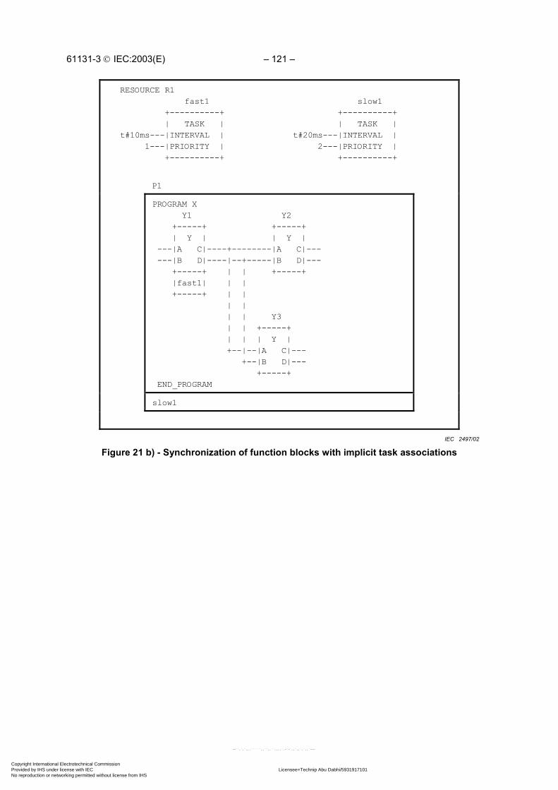
61131-3 IEC:2003(E) – 121 –
RESOURCE R1 fast1 +----------+ | TASK |t#10ms---|INTERVAL | 1---|PRIORITY | +----------+
slow1 +----------+ | TASK |t#20ms---|INTERVAL | 2---|PRIORITY | +----------+
P1
PROGRAM X Y1 Y2 +-----+ +-----+ | Y | | Y | ---|A C|----+--------|A C|--- ---|B D|----|--+-----|B D|--- +-----+ | | +-----+ |fast1| | | +-----+ | | | | | | Y3 | | +-----+ | | | Y | +--|--|A C|--- +--|B D|--- +-----+ END_PROGRAM
slow1
Figure 21 b) - Synchronization of function blocks with implicit task associationsIEC 2497/02
Copyright International Electrotechnical Commission Provided by IHS under license with IEC Licensee=Technip Abu Dabhi/5931917101
Not for Resale, 02/12/2006 07:01:30 MSTNo reproduction or networking permitted without license from IHS
--``,`,`,,,``````,,``,,``,,,,`,-`-`,,`,,`,`,,`---

– 122 – 61131-3 IEC:2003(E)
RESOURCE R1 fast1 +----------+ | TASK |t#10ms---|INTERVAL | 1---|PRIORITY | +----------+
slow1 +----------+ | TASK |t#20ms---|INTERVAL | 2---|PRIORITY | +----------+
P1
PROGRAM X Y1 Y2 +-----+ +-----+ | Y | | Y | ---|A C|----+--------|A C|--- ---|B D|----|--+-----|B D|--- +-----+ | | +-----+ |fast1| | | |slow1| +-----+ | | +-----+ | | | | Y3 | | +-----+ | | | Y | +--|--|A C|--- +--|B D|--- +-----+ |slow1| +-----+
END_PROGRAM
Figure 21 c) - Explicit task associations equivalent to figure 21 b)IEC 2498/02
Copyright International Electrotechnical Commission Provided by IHS under license with IEC Licensee=Technip Abu Dabhi/5931917101
Not for Resale, 02/12/2006 07:01:30 MSTNo reproduction or networking permitted without license from IHS
--``,`,`,,,``````,,``,,``,,,,`,-`-`,,`,,`,`,,`---

61131-3 IEC:2003(E) – 123 –
3 Textual languages
The textual languages defined in this standard are IL (Instruction List) and ST (Structured Text). Thesequential function chart (SFC) elements defined in 2.6 can be used in conjunction with either of theselanguages.
3.1 Common elements
The textual elements specified in clause 2 shall be common to the textual languages (IL and ST)defined in this clause. In particular, the following program structuring elements shall be common totextual languages:
TYPE...END_TYPE (2.3.3)
VAR...END_VAR (2.4.3)
VAR_INPUT...END_VAR (2.4.3)
VAR_OUTPUT...END_VAR (2.4.3)
VAR_IN_OUT...END_VAR (2.4.3)
VAR_EXTERNAL...END_VAR (2.4.3)
VAR_TEMP...END_VAR (2.4.3)
VAR_ACCESS...END_VAR (2.4.3)
VAR_GLOBAL...END_VAR (2.4.3)
VAR_CONFIG...END_VAR (2.4.3)
FUNCTION ... END_FUNCTION (2.5.1.3)
FUNCTION_BLOCK...END_FUNCTION_BLOCK (2.5.2.2)
PROGRAM...END_PROGRAM (2.5.3)
STEP...END_STEP (2.6.2)
TRANSITION...END_TRANSITION (2.6.3)
ACTION...END_ACTION (2.6.4)
3.2 Instruction list (IL)
This subclause defines the semantics of the IL (Instruction List) language whose formal syntax isgiven in B.2.
3.2.1 Instructions
As illustrated in table 51, an instruction list is composed of a sequence of instructions. Eachinstruction shall begin on a new line and shall contain an operator with optional modifiers, and, ifnecessary for the particular operation, one or more operands separated by commas. Operands canbe any of the data representations defined in 2.2 for literals, in 2.3.3 for enumerated values, and in 2.4for variables.
The instruction can be preceded by an identifying label followed by a colon (:). Empty lines can beinserted between instructions.
Copyright International Electrotechnical Commission Provided by IHS under license with IEC Licensee=Technip Abu Dabhi/5931917101
Not for Resale, 02/12/2006 07:01:30 MSTNo reproduction or networking permitted without license from IHS
--``,`,`,,,``````,,``,,``,,,,`,-`-`,,`,,`,`,,`---
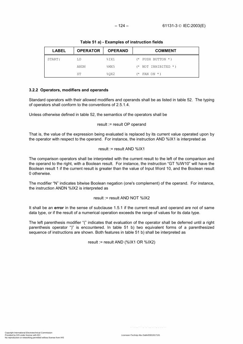
– 124 – 61131-3 IEC:2003(E)
Table 51 a) - Examples of instruction fields
LABEL OPERATOR OPERAND COMMENT
START: LD %IX1 (* PUSH BUTTON *)
ANDN %MX5 (* NOT INHIBITED *)
ST %QX2 (* FAN ON *)
3.2.2 Operators, modifiers and operands
Standard operators with their allowed modifiers and operands shall be as listed in table 52. The typingof operators shall conform to the conventions of 2.5.1.4.
Unless otherwise defined in table 52, the semantics of the operators shall be
result := result OP operand
That is, the value of the expression being evaluated is replaced by its current value operated upon bythe operator with respect to the operand. For instance, the instruction AND %IX1 is interpreted as
result := result AND %IX1
The comparison operators shall be interpreted with the current result to the left of the comparison andthe operand to the right, with a Boolean result. For instance, the instruction “GT %IW10” will have theBoolean result 1 if the current result is greater than the value of Input Word 10, and the Boolean result0 otherwise.
The modifier “N” indicates bitwise Boolean negation (one's complement) of the operand. For instance,the instruction ANDN %IX2 is interpreted as
result := result AND NOT %IX2
It shall be an error in the sense of subclause 1.5.1 if the current result and operand are not of samedata type, or if the result of a numerical operation exceeds the range of values for its data type.
The left parenthesis modifier “(” indicates that evaluation of the operator shall be deferred until a rightparenthesis operator “)” is encountered. In table 51 b) two equivalent forms of a parenthesizedsequence of instructions are shown. Both features in table 51 b) shall be interpreted as
result := result AND (%IX1 OR %IX2)
Copyright International Electrotechnical Commission Provided by IHS under license with IEC Licensee=Technip Abu Dabhi/5931917101
Not for Resale, 02/12/2006 07:01:30 MSTNo reproduction or networking permitted without license from IHS
--``,`,`,,,``````,,``,,``,,,,`,-`-`,,`,,`,`,,`---

61131-3 IEC:2003(E) – 125 –
Table 51 b) - Parenthesized expression features for IL language
No. DESCRIPTION/EXAMPLE
1 Parenthesized expression beginning with explicit operator:
AND(LD %IX1 (NOTE 1)OR %IX2)
2 Parenthesized expression (short form):
AND( %IX1OR %IX2)
NOTE In form 1 the LD operator may be modified or the LD operation may bereplaced by another operation or function invocation respectively.
The modifier “C” indicates that the associated instruction shall be performed only if the value of thecurrently evaluated result is Boolean 1 (or Boolean 0 if the operator is combined with the “N” modifier).
Table 52 - Instruction list operatorsNo. OPERATORa MODIFIERS
(Note 1)SEMANTICS
1 LD N Set current result equal to operand
2 ST N Store current result to operand location
3 Se Set operand to 1 if current result is Boolean 1
Re Reset operand to 0 if current result is Boolean1
4 AND N, ( Logical AND
5 & N, ( Logical AND
6 OR N, ( Logical OR
7 XOR N, ( Logical exclusive OR
7a NOTd Logical negation (one's complement)
8 ADD ( Addition
9 SUB ( Subtraction
10 MUL ( Multiplication
11 DIV ( Division
11a MOD ( Modulo-division
12 GT ( Comparison: >
13 GE ( Comparison: >=
14 EQ ( Comparison: =
15 NE ( Comparison: <>
16 LE ( Comparison: <=
17 LT ( Comparison: <
18 JMPb C, N Jump to label
19 CALc C, N Call function block (See table 53)
Copyright International Electrotechnical Commission Provided by IHS under license with IEC Licensee=Technip Abu Dabhi/5931917101
Not for Resale, 02/12/2006 07:01:30 MSTNo reproduction or networking permitted without license from IHS
--``,`,`,,,``````,,``,,``,,,,`,-`-`,,`,,`,`,,`---
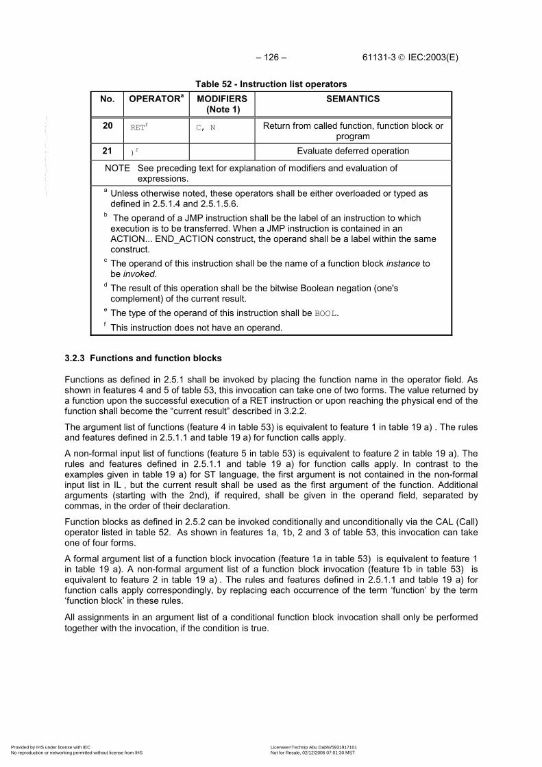
– 126 – 61131-3 IEC:2003(E)
Table 52 - Instruction list operatorsNo. OPERATORa MODIFIERS
(Note 1)SEMANTICS
20 RETf C, N Return from called function, function block orprogram
21 )f Evaluate deferred operation
NOTE See preceding text for explanation of modifiers and evaluation ofexpressions.
a Unless otherwise noted, these operators shall be either overloaded or typed asdefined in 2.5.1.4 and 2.5.1.5.6.
b The operand of a JMP instruction shall be the label of an instruction to whichexecution is to be transferred. When a JMP instruction is contained in anACTION... END_ACTION construct, the operand shall be a label within the sameconstruct.
c The operand of this instruction shall be the name of a function block instance tobe invoked.
d The result of this operation shall be the bitwise Boolean negation (one'scomplement) of the current result.
e The type of the operand of this instruction shall be BOOL.f This instruction does not have an operand.
3.2.3 Functions and function blocks
Functions as defined in 2.5.1 shall be invoked by placing the function name in the operator field. Asshown in features 4 and 5 of table 53, this invocation can take one of two forms. The value returned bya function upon the successful execution of a RET instruction or upon reaching the physical end of thefunction shall become the “current result” described in 3.2.2.
The argument list of functions (feature 4 in table 53) is equivalent to feature 1 in table 19 a) . The rulesand features defined in 2.5.1.1 and table 19 a) for function calls apply.
A non-formal input list of functions (feature 5 in table 53) is equivalent to feature 2 in table 19 a). Therules and features defined in 2.5.1.1 and table 19 a) for function calls apply. In contrast to theexamples given in table 19 a) for ST language, the first argument is not contained in the non-formalinput list in IL , but the current result shall be used as the first argument of the function. Additionalarguments (starting with the 2nd), if required, shall be given in the operand field, separated bycommas, in the order of their declaration.
Function blocks as defined in 2.5.2 can be invoked conditionally and unconditionally via the CAL (Call)operator listed in table 52. As shown in features 1a, 1b, 2 and 3 of table 53, this invocation can takeone of four forms.
A formal argument list of a function block invocation (feature 1a in table 53) is equivalent to feature 1in table 19 a). A non-formal argument list of a function block invocation (feature 1b in table 53) isequivalent to feature 2 in table 19 a) . The rules and features defined in 2.5.1.1 and table 19 a) forfunction calls apply correspondingly, by replacing each occurrence of the term ‘function’ by the term‘function block’ in these rules.
All assignments in an argument list of a conditional function block invocation shall only be performedtogether with the invocation, if the condition is true.
Copyright International Electrotechnical Commission Provided by IHS under license with IEC Licensee=Technip Abu Dabhi/5931917101
Not for Resale, 02/12/2006 07:01:30 MSTNo reproduction or networking permitted without license from IHS
--``,`,`,,,``````,,``,,``,,,,`,-`-`,,`,,`,`,,`---

61131-3 IEC:2003(E) – 127 –
Table 53 - Function block invocation andFunction invocation features for IL language
No. DESCRIPTION/EXAMPLE
1a CAL of function block with non-formal argument list:
CAL C10(%IX10, FALSE, A, OUT, B)
CAL CMD_TMR(%IX5, T#300ms, OUT, ELAPSED)
1b CAL of function block with formal argument list:
CAL C10( CU := %IX10, Q => OUT)
CAL CMD_TMR( IN := %IX5, PT := T#300ms, Q => OUT, ET => ELAPSED, ENO => ERR)
2 CAL of function block with load/store of arguments (note 2)
LD AADD 5ST C10.PVLD %IX10ST C10.CUCAL C10
3 Use of function block input operators:
LD AADD 5PV C10LD %IX10CU C10
4 Function invocation with formal argument list:
LIMIT( EN:= COND, IN:= B, MN:= 1, MX:= 5, ENO=> TEMPL)ST A
5 Function invocation with non-formal argument list:
LD 1LIMIT B, 5ST A
Copyright International Electrotechnical Commission Provided by IHS under license with IEC Licensee=Technip Abu Dabhi/5931917101
Not for Resale, 02/12/2006 07:01:30 MSTNo reproduction or networking permitted without license from IHS
--``,`,`,,,``````,,``,,``,,,,`,-`-`,,`,,`,`,,`---

– 128 – 61131-3 IEC:2003(E)
Table 53 - Function block invocation andFunction invocation features for IL language
No. DESCRIPTION/EXAMPLENOTE 1 A declaration such as
VAR C10 : CTU; CMD_TMR : TON; A, B : INT; ELAPSED : TIME; OUT, ERR, TEMPL, COND : BOOL;END_VARis assumed in the above examples.
NOTE 2 This usage is an exception to the rule given in 2.5.2.1that “The assignment of a value to the inputs of a functionblock is permitted only as part of the invocation of thefunction block.”
The input operators shown in table 54 can be used in conjunction with feature 3 of table 53. Thismethod of invocation is equivalent to a CAL with an argument list, which contains only one variablewith the name of the input operator. Arguments, which are not supplied, are taken from the lastassignment or, if not present, from initialization. This feature supports problem situations, whereevents are predictable and therefore only one variable can change from one call to the next.
EXAMPLE 1Together with the declarationVAR C10: CTU; END_VARthe instruction sequence
LD 15PV C10
gives the same result asCAL C10(PV:=15)
The missing inputs R and CU have values previously assigned to them. Since the CU inputdetects a rising edge, only the PV input value will be set by this call; counting cannothappen because an unsupplied argument cannot change. In contrast to this, thesequence
LD %IX10CU C10
results in counting at maximum in every second call, depending on the change rate of theinput %IX10. Every call uses the previously set values for PV and R.
EXAMPLE 2With bistable function blocks, taking a declarationVAR FORWARD: SR; END_VARthis results into an implicit conditional behavior. The sequence
LD FALSES1 FORWARD
does not change the state of the bistable FORWARD. A following sequenceLD TRUER FORWARD
resets the bistable.
Copyright International Electrotechnical Commission Provided by IHS under license with IEC Licensee=Technip Abu Dabhi/5931917101
Not for Resale, 02/12/2006 07:01:30 MSTNo reproduction or networking permitted without license from IHS
--``,`,`,,,``````,,``,,``,,,,`,-`-`,,`,,`,`,,`---

61131-3 IEC:2003(E) – 129 –
Table 54 - Standard function block input operators for IL language
No. Operators FB Type Reference
4 S1,R SR 2.5.2.3.1
5 S,R1 RS 2.5.2.3.1
6 CLK TRIGGER 2.5.2.3.2
8 CU,R,PV CTU 2.5.2.3.3
9 CD,PV CTD 2.5.2.3.3 (note 1)
10 CU,CD,R,PV CTUD 2.5.2.3.3 (note 1)
11 IN,PT TP 2.5.2.3.4
12 IN,PT TON 2.5.2.3.4
13 IN,PT TOF 2.5.2.3.4NOTE 1 LD is not necessary as a Standard Function Block input
operator, because the LD functionality is included in PV.
NOTE 2 The feature numbering in this table is such as tomaintain consistency with the first edition of IEC 61131-3.
3.3 Structured Text (ST)
This subclause defines the semantics of the ST (Structured Text) language whose syntax is defined inB.3. In this language, the end of a textual line shall be treated the same as a space (SP) character, asdefined in 2.1.4.
3.3.1 Expressions
An expression is a construct which, when evaluated, yields a value corresponding to one of the datatypes defined in 2.3.1 and 2.3.3. The maximum allowed length of expressions is an implementation-dependent parameter.
Expressions are composed of operators and operands. An operand shall be a literal as defined in 2.2,an enumerated value as defined in 2.3.3, a variable as defined in 2.4, a function invocation as definedin 2.5.1, or another expression.
The operators of the ST language are summarized in table 55. The evaluation of an expressionconsists of applying the operators to the operands in a sequence defined by the operator precedenceshown in table 55. The operator with highest precedence in an expression shall be applied first,followed by the operator of next lower precedence, etc., until evaluation is complete. Operators ofequal precedence shall be applied as written in the expression from left to right. For example, if A, B,C, and D are of type INT with values 1, 2, 3, and 4, respectively, then
A+B-C*ABS(D)shall evaluate to -9, and
(A+B-C)*ABS(D)shall evaluate to 0.
Copyright International Electrotechnical Commission Provided by IHS under license with IEC Licensee=Technip Abu Dabhi/5931917101
Not for Resale, 02/12/2006 07:01:30 MSTNo reproduction or networking permitted without license from IHS
--``,`,`,,,``````,,``,,``,,,,`,-`-`,,`,,`,`,,`---

– 130 – 61131-3 IEC:2003(E)
When an operator has two operands, the leftmost operand shall be evaluated first. For example, inthe expression
SIN(A)*COS(B)the expression SIN(A) shall be evaluated first, followed by COS(B), followed by evaluation of theproduct.
The following conditions in the execution of operators shall be treated as errors in the sense ofsubclause 1.5.1:
1) An attempt is made to divide by zero.
2) Operands are not of the correct data type for the operation.
3) The result of a numerical operation exceeds the range of values for its data type.
Boolean expressions may be evaluated only to the extent necessary to determine the resultant value.For instance, if A<=B, then only the expression (A>B) would be evaluated to determine that the valueof the expression
(A>B) & (C<D)is Boolean zero.
Functions shall be invoked as elements of expressions consisting of the function name followed by aparenthesized list of arguments, as defined in 2.5.1.1.
When an operator in an expression can be represented as one of the overloaded functions defined in2.5.1.5, conversion of operands and results shall follow the rule and examples given in 2.5.1.4.
Copyright International Electrotechnical Commission Provided by IHS under license with IEC Licensee=Technip Abu Dabhi/5931917101
Not for Resale, 02/12/2006 07:01:30 MSTNo reproduction or networking permitted without license from IHS
--``,`,`,,,``````,,``,,``,,,,`,-`-`,,`,,`,`,,`---

61131-3 IEC:2003(E) – 131 –
Table 55 - Operators of the ST language
No. Operationa Symbol Precedence
1 Parenthesization (expression) HIGHEST
2 Function evaluation identifier(argument list)
EXAMPLES LN(A), MAX(X,Y), etc.
4 Negation -
5 Complement NOT
3 Exponentiationb **
6 Multiply *
7 Divide /
8 Modulo MOD
9 Add +
10 Subtract -
11 Comparison < , > , <= , >=
12 Equality =
13 Inequality <>
14 Boolean AND &
15 Boolean AND AND
16 Boolean Exclusive OR XOR
17 Boolean OR OR LOWESTNOTE The feature numbering in this table is such as to maintain consistency with the first edition
of IEC 61131-3.a The same restrictions apply to the operands of these operators as to the inputs of the
corresponding functions defined in 2.5.1.5.b The result of evaluating the expression A**B shall be the same as the result of evaluating the
function EXPT(A,B) as defined in table 24.
3.3.2 Statements
The statements of the ST language are summarized in table 56. Statements shall be terminated bysemicolons as specified in the syntax of B.3. The maximum allowed length of statements is animplementation-dependent parameter.
Copyright International Electrotechnical Commission Provided by IHS under license with IEC Licensee=Technip Abu Dabhi/5931917101
Not for Resale, 02/12/2006 07:01:30 MSTNo reproduction or networking permitted without license from IHS
--``,`,`,,,``````,,``,,``,,,,`,-`-`,,`,,`,`,,`---
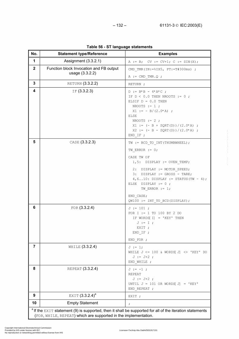
– 132 – 61131-3 IEC:2003(E)
Table 56 - ST language statementsNo. Statement type/Reference Examples
1 Assignment (3.3.2.1) A := B; CV := CV+1; C := SIN(X);
2 Function block Invocation and FB outputusage (3.3.2.2)
CMD_TMR(IN:=%IX5, PT:=T#300ms) ;
A := CMD_TMR.Q ;
3 RETURN (3.3.2.2) RETURN ;
4 IF (3.3.2.3) D := B*B - 4*A*C ;IF D < 0.0 THEN NROOTS := 0 ;ELSIF D = 0.0 THEN NROOTS := 1 ; X1 := - B/(2.0*A) ;ELSE NROOTS := 2 ; X1 := (- B + SQRT(D))/(2.0*A) ; X2 := (- B - SQRT(D))/(2.0*A) ;END_IF ;
5 CASE (3.3.2.3) TW := BCD_TO_INT(THUMBWHEEL);
TW_ERROR := 0;
CASE TW OF 1,5: DISPLAY := OVEN_TEMP;
2: DISPLAY := MOTOR_SPEED; 3: DISPLAY := GROSS - TARE; 4,6..10: DISPLAY := STATUS(TW - 4);ELSE DISPLAY := 0 ; TW_ERROR := 1;
END_CASE;QW100 := INT_TO_BCD(DISPLAY);
6 FOR (3.3.2.4) J := 101 ;FOR I := 1 TO 100 BY 2 DO IF WORDS[I] = 'KEY' THEN J := I ; EXIT ; END_IF ;
END_FOR ;
7 WHILE (3.3.2.4) J := 1;WHILE J <= 100 & WORDS[J] <> 'KEY' DO J := J+2 ;END_WHILE ;
8 REPEAT (3.3.2.4) J := -1 ;REPEAT J := J+2 ;UNTIL J = 101 OR WORDS[J] = 'KEY'END_REPEAT ;
9 EXIT (3.3.2.4)aEXIT ;
10 Empty Statement ;a If the EXIT statement (9) is supported, then it shall be supported for all of the iteration statements
(FOR, WHILE, REPEAT) which are supported in the implementation.
Copyright International Electrotechnical Commission Provided by IHS under license with IEC Licensee=Technip Abu Dabhi/5931917101
Not for Resale, 02/12/2006 07:01:30 MSTNo reproduction or networking permitted without license from IHS
--``,`,`,,,``````,,``,,``,,,,`,-`-`,,`,,`,`,,`---

61131-3 IEC:2003(E) – 133 –
3.3.2.1 Assignment statements
The assignment statement replaces the current value of a single or multi-element variable by theresult of evaluating an expression. An assignment statement shall consist of a variable reference onthe left-hand side, followed by the assignment operator “:=”, followed by the expression to beevaluated. For instance, the statement
A := B ;
would be used to replace the single data value of variable A by the current value of variable B if bothwere of type INT. However, if both A and B were of type ANALOG_CHANNEL_CONFIGURATION asdescribed in table 12, then the values of all the elements of the structured variable A would bereplaced by the current values of the corresponding elements of variable B.
As illustrated in figure 6, the assignment statement shall also be used to assign the value to be returned bya function, by placing the function name to the left of an assignment operator in the body of the functiondeclaration. The value returned by the function shall be the result of the most recent evaluation of such anassignment. It is an error to return from the evaluation of a function with an ENO value of TRUE, or with anon-existent ENO output, unless at least one such assignment has been made.
3.3.2.2 Function and function block control statements
Function and function block control statements consist of the mechanisms for invoking function blocksand for returning control to the invoking entity before the physical end of a function or function block.
Function evaluation shall be invoked as part of expression evaluation, as specified in 3.3.1.
Function blocks shall be invoked by a statement consisting of the name of the function block instancefollowed by a parenthesized list of arguments, as illustrated in table 56. The rules and features definedin 2.5.1.1 and table 19 a) for function calls apply correspondingly, by replacing each occurrence of theterm ‘function’ by the term ‘function block’ in these rules.
The RETURN statement shall provide early exit from a function, function block or program (for example,as the result of the evaluation of an IF statement).
3.3.2.3 Selection statements
Selection statements include the IF and CASE statements. A selection statement selects one (or agroup) of its component statements for execution, based on a specified condition. Examples ofselection statements are given in table 56.
The IF statement specifies that a group of statements is to be executed only if the associated Booleanexpression evaluates to the value 1 (true). If the condition is false, then either no statement is to beexecuted, or the statement group following the ELSE keyword (or the ELSIF keyword if its associatedBoolean condition is true) is to be executed.
The CASE statement consists of an expression which shall evaluate to a variable of type ANY_INT orof an enumerated data type (the “selector”), and a list of statement groups, each group being labeledby one or more integer or enumerated values or ranges of integer values, as applicable. It specifiesthat the first group of statements, one of whose ranges contains the computed value of the selector,shall be executed . If the value of the selector does not occur in a range of any case, the statementsequence following the keyword ELSE (if it occurs in the CASE statement) shall be executed.Otherwise, none of the statement sequences shall be executed.
The maximum allowed number of selections in CASE statements is an implementation-dependentparameter.
Copyright International Electrotechnical Commission Provided by IHS under license with IEC Licensee=Technip Abu Dabhi/5931917101
Not for Resale, 02/12/2006 07:01:30 MSTNo reproduction or networking permitted without license from IHS
--``,`,`,,,``````,,``,,``,,,,`,-`-`,,`,,`,`,,`---

– 134 – 61131-3 IEC:2003(E)
3.3.2.4 Iteration statements
Iteration statements specify that the group of associated statements shall be executed repeatedly. TheFOR statement is used if the number of iterations can be determined in advance; otherwise, the WHILEor REPEAT constructs are used.
The EXIT statement shall be used to terminate iterations before the termination condition is satisfied.
When the EXIT statement is located within nested iterative constructs, exit shall be from the innermostloop in which the EXIT is located, that is, control shall pass to the next statement after the first loopterminator (END_FOR, END_WHILE, or END_REPEAT) following the EXIT statement. For instance, afterexecuting the statements shown in figure 22, the value of the variable SUM shall be 15 if the value ofthe Boolean variable FLAG is 0, and 6 if FLAG=1.
SUM := 0 ;FOR I := 1 TO 3 DO FOR J := 1 TO 2 DO IF FLAG THEN EXIT ; END_IF SUM := SUM + J ; END_FOR ; SUM := SUM + I ;END_FOR ;
Figure 22 - EXIT statement example
The FOR statement indicates that a statement sequence shall be repeatedly executed, up to theEND_FOR keyword, while a progression of values is assigned to the FOR loop control variable. Thecontrol variable, initial value, and final value shall be expressions of the same integer type (forexample, SINT, INT, or DINT) and shall not be altered by any of the repeated statements. The FORstatement increments the control variable up or down from an initial value to a final value inincrements determined by the value of an expression; this value defaults to 1. The test for thetermination condition is made at the beginning of each iteration, so that the statement sequence is notexecuted if the initial value exceeds the final value. The value of the control variable after completionof the FOR loop is implementation-dependent.
An example of the usage of the FOR statement is given in feature 6 of table 56. In this example, theFOR loop is used to determine the index J of the first occurrence (if any) of the string 'KEY' in the odd-numbered elements of an array of strings WORDS with a subscript range of (1..100). If no occurrenceis found, J will have the value 101.
The WHILE statement causes the sequence of statements up to the END_WHILE keyword to beexecuted repeatedly until the associated Boolean expression is false. If the expression is initiallyfalse, then the group of statements is not executed at all. For instance, the FOR...END_FOR examplegiven in table 56 can be rewritten using the WHILE...END_WHILE construction shown in table 56.
The REPEAT statement causes the sequence of statements up to the UNTIL keyword to be executedrepeatedly (and at least once) until the associated Boolean condition is true. For instance, theWHILE...END_WHILE example given in table 56 can be rewritten using the REPEAT...END_REPEATconstruction shown in table 56.
The WHILE and REPEAT statements shall not be used to achieve interprocess synchronization, forexample as a "wait loop" with an externally determined termination condition. The SFC elementsdefined in 2.6 shall be used for this purpose.
It shall be an error in the sense of 1.5.1 if a WHILE or REPEAT statement is used in an algorithm forwhich satisfaction of the loop termination condition or execution of an EXIT statement cannot beguaranteed.
IEC 2499/02
Copyright International Electrotechnical Commission Provided by IHS under license with IEC Licensee=Technip Abu Dabhi/5931917101
Not for Resale, 02/12/2006 07:01:30 MSTNo reproduction or networking permitted without license from IHS
--``,`,`,,,``````,,``,,``,,,,`,-`-`,,`,,`,`,,`---

61131-3 IEC:2003(E) – 135 –
4 Graphic languages
The graphic languages defined in this standard are LD (Ladder Diagram) and FBD (Function BlockDiagram). The sequential function chart (SFC) elements defined in 2.6 can be used in conjunctionwith either of these languages.
4.1 Common elements
The elements defined in this clause apply to both the graphic languages in this standard, that is, LD(Ladder Diagram) and FBD (Function Block Diagram), and to the graphic representation of sequentialfunction chart (SFC) elements.
4.1.1 Representation of lines and blocks
The graphic language elements defined in this clause are drawn with line elements using charactersfrom the character set defined in 2.1.1, or using graphic or semigraphic elements, as shown in table57.
Lines can be extended by the use of connectors as shown in table 57. No storage of data orassociation with data elements shall be associated with the use of connectors; hence, to avoidambiguity, it shall be an error if the identifier used as a connector label is the same as the name ofanother named element within the same program organization unit.
Any restrictions on network topology in a particular implementation shall be expressed asimplementation-dependent parameters.
4.1.2 Direction of flow in networks
A network is defined as a maximal set of interconnected graphic elements, excluding the left and rightrails in the case of networks in the LD language defined in 4.2. Provision shall be made to associatewith each network or group of networks in a graphic language a network label delimited on the right bya colon (:). This label shall have the form of an identifier or an unsigned decimal integer as defined inclause 2. The scope of a network and its label shall be local to the program organization unit in whichthe network is located. Examples of networks and network labels are shown in annex F.
Graphic languages are used to represent the flow of a conceptual quantity through one or morenetworks representing a control plan, that is:
- “Power flow”, analogous to the flow of electric power in an electromechanical relay system,typically used in relay ladder diagrams;
- “Signal flow”, analogous to the flow of signals between elements of a signal processing system,typically used in function block diagrams;
- “Activity flow”, analogous to the flow of control between elements of an organization, or betweenthe steps of an electromechanical sequencer, typically used in sequential function charts.
The appropriate conceptual quantity shall flow along lines between elements of a network according tothe following rules:
1) Power flow in the LD language shall be from left to right.
2) Signal flow in the FBD language shall be from the output (right-hand) side of a function orfunction block to the input (left-hand) side of the function or function block(s) so connected.
3) Activity flow between the SFC elements defined in 2.6 shall be from the bottom of a stepthrough the appropriate transition to the top of the corresponding successor step(s).
Copyright International Electrotechnical Commission Provided by IHS under license with IEC Licensee=Technip Abu Dabhi/5931917101
Not for Resale, 02/12/2006 07:01:30 MSTNo reproduction or networking permitted without license from IHS
--``,`,`,,,``````,,``,,``,,,,`,-`-`,,`,,`,`,,`---

– 136 – 61131-3 IEC:2003(E)
Table 57 - Representation of lines and blocks
No. Feature Example
12
Horizontal lines:ISO/IEC 10646-1 “minus” character
Graphic or semigraphic-----
34
Vertical lines:ISO/IEC 10646-1 “vertical line” character
Graphic or semigraphic|
5
6
Horizontal/vertical connection:ISO/IEC 10646-1 “plus” character
Graphic or semigraphic
|--+-- |
7
8
Line crossings without connection:ISO/IEC 10646-1 characters
Graphic or semigraphic
| |--------|---- | |
9
10
Connected and non-connected corners:
ISO/IEC 10646-1 characters
Graphic or semigraphic
| | ----+ +---- | ----+-+ +---- | | |
11
12
Blocks with connecting lines:
ISO/IEC 10646-1 characters
Graphic or semigraphic
| +--------+ ---| | | |--- ---| | +--------+ |
13
14
Connectors using ISO/IEC 10646-1 characters:Connector
Continuation of a connected lineGraphic or semigraphic connectors
---------->OTTO>>OTTO>----------
4.1.3 Evaluation of networks
The order in which networks and their elements are evaluated is not necessarily the same as theorder in which they are labeled or displayed. Similarly, it is not necessary that all networks beevaluated before the evaluation of a given network can be repeated. However, when the body of aprogram organization unit consists of one or more networks, the results of network evaluation withinthe said body shall be functionally equivalent to the observance of the following rules:
1) No element of a network shall be evaluated until the states of all of its inputs have beenevaluated.
2) The evaluation of a network element shall not be complete until the states of all of its outputshave been evaluated.
3) The evaluation of a network is not complete until the outputs of all of its elements have beenevaluated, even if the network contains one of the execution control elements defined in 4.1.4.
Copyright International Electrotechnical Commission Provided by IHS under license with IEC Licensee=Technip Abu Dabhi/5931917101
Not for Resale, 02/12/2006 07:01:30 MSTNo reproduction or networking permitted without license from IHS
--``,`,`,,,``````,,``,,``,,,,`,-`-`,,`,,`,`,,`---

61131-3 IEC:2003(E) – 137 –
4) The order in which networks are evaluated shall conform to the provisions of 4.2.6 for the LDlanguage and 4.3.3 for the FBD language.
A feedback path is said to exist in a network when the output of a function or function block is used asthe input to a function or function block which precedes it in the network; the associated variable iscalled a feedback variable. For instance, the Boolean variable RUN is the feedback variable in theexample shown in figure 23. A feedback variable can also be an output element of a function blockdata structure as defined in 2.5.2.
Feedback paths can be utilized in the graphic languages defined in 4.2 and 4.3, subject to thefollowing rules:
1) Explicit loops such as the one shown in figure 23 a) shall only appear in the FBD languagedefined in 4.3.
2) It shall be possible for the user to utilize an implementation-dependent means to determinethe order of execution of the elements in an explicit loop, for instance by selection of feedbackvariables to form an implicit loop as shown in figure 23 b).
3) Feedback variables shall be initialized by one of the mechanisms defined in clause 2. The initialvalue shall be used during the first evaluation of the network. It shall be an error if a feedbackvariable is not initialized.
4) Once the element with a feedback variable as output has been evaluated, the new value of thefeedback variable shall be used until the next evaluation of the element.
a) +---+ ENABLE---| & |-----RUN---+ +---| | | +---+ | +---+ | START1---|>=1|---+ | START2---| | | +--| | | | +---+ | +------------------------------+
b) +---+ ENABLE---| & |-----RUN +---| | +---+ | +---+ START1---|>=1|---+ START2---| | RUN---| | +---+
c) | START1 ENABLE RUN | +---| |----+---| |------( )---+ | START2 | | +---| |----+ | | RUN | | +---| |----+ | | |
Figure 23 - Feedback path examplea) Explicit loopb) Implicit loop
c) LD language equivalent
IEC 2500/02
Copyright International Electrotechnical Commission Provided by IHS under license with IEC Licensee=Technip Abu Dabhi/5931917101
Not for Resale, 02/12/2006 07:01:30 MSTNo reproduction or networking permitted without license from IHS
--``,`,`,,,``````,,``,,``,,,,`,-`-`,,`,,`,`,,`---

– 138 – 61131-3 IEC:2003(E)
4.1.4 Execution control elements
Transfer of program control in the LD and FBD languages shall be represented by the graphicalelements shown in table 58.
Jumps shall be shown by a Boolean signal line terminated in a double arrowhead. The signal line fora jump condition shall originate at a Boolean variable, at a Boolean output of a function or functionblock, or on the power flow line of a ladder diagram. A transfer of program control to the designatednetwork label shall occur when the Boolean value of the signal line is 1 (TRUE); thus, the unconditionaljump is a special case of the conditional jump.
The target of a jump shall be a network label within the program organization unit within which thejump occurs. If the jump occurs within an ACTION...END_ACTION construct, the target of the jumpshall be within the same construct.
Conditional returns from functions and function blocks shall be implemented using a RETURNconstruction as shown in table 58. Program execution shall be transferred back to the invoking entitywhen the Boolean input is 1 (TRUE), and shall continue in the normal fashion when the Boolean inputis 0 (FALSE). Unconditional returns shall be provided by the physical end of the function or functionblock, or by a RETURN element connected to the left rail in the LD language, as shown in table 58.
Table 58 - Graphic execution control elementsNo. Symbol/Example Explanation
1
2
1---->>LABELA
| +---->>LABELA |
Unconditional Jjump:FBD language
LD language
3 X---->>LABELB
+---+ %IX20---| & |--->>NEXT %MX50---| | +---+ NEXT: +---+ %IX25---|>=1|---%QX100 %MX60---| | +---+
Conditional jump(FBD language)
Example:jump condition
jump target
4 | X +-| |---->>LABELB | | | %IX20 %MX50 +---| |-----| |--->>NEXT | | NEXT: | %IX25 %QX100 | +----| |----+----( )---+ | %MX60 | | +----| |----+ | | |
Conditional jump(LD language)
Example:jump condition
jump target
Copyright International Electrotechnical Commission Provided by IHS under license with IEC Licensee=Technip Abu Dabhi/5931917101
Not for Resale, 02/12/2006 07:01:30 MSTNo reproduction or networking permitted without license from IHS
--``,`,`,,,``````,,``,,``,,,,`,-`-`,,`,,`,`,,`---

61131-3 IEC:2003(E) – 139 –
Table 58 - Graphic execution control elementsNo. Symbol/Example Explanation
5
6
| X +--| |---<RETURN> |
X---<RETURN>
Conditional return:LD language
FBD language
7
8
END_FUNCTION
END_FUNCTION_BLOCK
| +---<RETURN> |
Unconditional return:from FUNCTION
from FUNCTION_BLOCKAlternative representation
in LD language
4.2 Ladder diagram (LD)
This subclause defines the LD language for ladder diagram programming of programmablecontrollers.
A LD program enables the programmable controller to test and modify data by means of standardizedgraphic symbols. These symbols are laid out in networks in a manner similar to a “rung” of a relayladder logic diagram. LD networks are bounded on the left and right by power rails.
4.2.1 Power rails
As shown in table 59, the LD network shall be delimited on the left by a vertical line known as the leftpower rail, and on the right by a vertical line known as the right power rail. The right power rail may beexplicit or implied.
Table 59 - Power rails
No. Symbol Description
1 | +--- |
Left power rail(with attached horizontal link)
2 | ---+ |
Right power rail(with attached horizontal link)
4.2.2 Link elements and states
As shown in table 60, link elements may be horizontal or vertical. The state of the link element shallbe denoted “ON” or “OFF”, corresponding to the literal Boolean values 1 or 0, respectively. The termlink state shall be synonymous with the term power flow.
The state of the left rail shall be considered ON at all times.. No state is defined for the right rail.
A horizontal link element shall be indicated by a horizontal line. A horizontal link element transmits thestate of the element on its immediate left to the element on its immediate right.
Copyright International Electrotechnical Commission Provided by IHS under license with IEC Licensee=Technip Abu Dabhi/5931917101
Not for Resale, 02/12/2006 07:01:30 MSTNo reproduction or networking permitted without license from IHS
--``,`,`,,,``````,,``,,``,,,,`,-`-`,,`,,`,`,,`---

– 140 – 61131-3 IEC:2003(E)
The vertical link element shall consist of a vertical line intersecting with one or more horizontal linkelements on each side. The state of the vertical link shall represent the inclusive OR of the ON statesof the horizontal links on its left side, that is, the state of the vertical link shall be:
- OFF if the states of all the attached horizontal links to its left are OFF;
- ON if the state of one or more of the attached horizontal links to its left is ON.
The state of the vertical link shall be copied to all of the attached horizontal links on its right. The stateof the vertical link shall not be copied to any of the attached horizontal links on its left.
Table 60 - Link elements
No. Symbol Description
1 ----------- Horizontal link
2 | ----+---- ----+ | +----
Vertical link(with attached horizontal links)
4.2.3 Contacts
A contact is an element which imparts a state to the horizontal link on its right side which is equal tothe Boolean AND of the state of the horizontal link at its left side with an appropriate function of anassociated Boolean input, output, or memory variable. A contact does not modify the value of theassociated Boolean variable. Standard contact symbols are given in table 61.
4.2.4 Coils
A coil copies the state of the link on its left to the link on its right without modification, and stores anappropriate function of the state or transition of the left link into the associated Boolean variable.Standard coil symbols are given in table 62.
EXAMPLE In the rung shown below, the value of the Boolean output a is always TRUE, while thevalue of outputs c, d and e upon completion of an evaluation of the rung is equal to the value of theinput b.
| a b c d |+--( )--| |--+--( )---( )--+| | e || +-----( )-----+| |
4.2.5 Functions and function blocks
The representation of functions and function blocks in the LD language shall be as defined in clause 2,with the following exceptions:
1) Actual variable connections may optionally be shown by writing the appropriate data or variableoutside the block adjacent to the formal variable name on the inside.
Copyright International Electrotechnical Commission Provided by IHS under license with IEC Licensee=Technip Abu Dabhi/5931917101
Not for Resale, 02/12/2006 07:01:30 MSTNo reproduction or networking permitted without license from IHS
--``,`,`,,,``````,,``,,``,,,,`,-`-`,,`,,`,`,,`---

61131-3 IEC:2003(E) – 141 –
2) At least one Boolean input and one Boolean output shall be shown on each block to allow forpower flow through the block.
4.2.6 Order of network evaluation
Within a program organization unit written in LD, networks shall be evaluated in top to bottom order asthey appear in the ladder diagram, except as this order is modified by the execution control elementsdefined in 4.1.4.
Table 61 - Contacts a
Static contacts
No. Symbol Description
1
2
***--| |--
or
***--! !--
Normally open contactThe state of the left link is copied to the right link if thestate of the associated Boolean variable (indicated by"***") is ON. Otherwise, the state of the right link is
OFF.
3
4
***--|/|--
or
***--!/!--
Normally closed contactThe state of the left link is copied to the right link if the
state of the associated Boolean variable is OFF.Otherwise, the state of the right link is OFF.
Transition-sensing contacts
5
6
***--|P|--
or
***--!P!--
Positive transition-sensing contactThe state of the right link is ON from one evaluation of
this element to the next when a transition of theassociated variable from OFF to ON is sensed at the
same time that the state of the left link is ON. The stateof the right link shall be OFF at all other times.
7
8
***--|N|--
or
***--!N!--
Negative transition-sensing contactThe state of the right link is ON from one evaluation of
this element to the next when a transition of theassociated variable from ON to OFF is sensed at the
same time that the state of the left link is ON. The stateof the right link shall be OFF at all other times.
a As specified in 2.1.1, the exclamation mark “!” shall be used when a nationalcharacter set does not support the vertical bar “|”.
Copyright International Electrotechnical Commission Provided by IHS under license with IEC Licensee=Technip Abu Dabhi/5931917101
Not for Resale, 02/12/2006 07:01:30 MSTNo reproduction or networking permitted without license from IHS
--``,`,`,,,``````,,``,,``,,,,`,-`-`,,`,,`,`,,`---

– 142 – 61131-3 IEC:2003(E)
Table 62 - Coils
No. Symbol Description
Momentary coils
1***--( )--
CoilThe state of the left link is copied to the associated
Boolean variable and to the right link.
2***--(/)--
Negated coilThe state of the left link is copied to the right link. The
inverse of the state of the left link is copied to theassociated Boolean variable, that is, if the state of the
left link is OFF, then the state of the associated variableis ON, and vice versa.
Latched Coils
3***--(S)--
SET (latch) coilThe associated Boolean variable is set to the ON statewhen the left link is in the ON state, and remains set
until reset by a RESET coil.
4***--(R)--
RESET (unlatch) coilThe associated Boolean variable is reset to the OFF
state when the left link is in the ON state, and remainsreset until set by a SET coil.
Transition-sensing coils
8***--(P)--
Positive transition-sensing coilThe state of the associated Boolean variable is ON from
one evaluation of this element to the next when atransition of the left link from OFF to ON is sensed. The
state of the left link is always copied to the right link.
9***--(N)--
Negative transition-sensing coilThe state of the associated Boolean variable is ON from
one evaluation of this element to the next when atransition of the left link from ON to OFF is sensed. The
state of the left link is always copied to the right link.
NOTE Features 5, 6 and 7 of the first edition are deleted in this edition.
Copyright International Electrotechnical Commission Provided by IHS under license with IEC Licensee=Technip Abu Dabhi/5931917101
Not for Resale, 02/12/2006 07:01:30 MSTNo reproduction or networking permitted without license from IHS
--``,`,`,,,``````,,``,,``,,,,`,-`-`,,`,,`,`,,`---

61131-3 IEC:2003(E) – 143 –
4.3 Function Block Diagram (FBD)
4.3.1 General
This subclause defines FBD, a graphic language for the programming of programmable controllerswhich is consistent, as far as possible, with IEC 60617-12. Where conflicts exist between thisstandard and IEC 60617-12, the provisions of this standard shall apply for the programming ofprogrammable controllers in the FBD language.
The provisions of clause 2 and subclause 4.1 shall apply to the construction and interpretation ofprogrammable controller programs in the FBD language.
Examples of the use of the FBD language are given in annex F.
4.3.2 Combination of elements
Elements of the FBD language shall be interconnected by signal flow lines following the conventionsof 4.1.2.
Outputs of function blocks shall not be connected together. In particular, the “wired-OR” construct ofthe LD language is not allowed in the FBD language; an explicit Boolean “OR” block is requiredinstead, as shown in figure 24.
a) b)
| a c |+---||--+--()--+| b | |+--||---+ || |
+-----+ a---| >=1 |---c b---| | +-----+
Figure 24 - Boolean OR examplesa) “Wired-OR” in LD languageb) Function in FBD language
4.3.3 Order of network evaluation
When a program organization unit written in the FBD language contains more than one network, themanufacturer shall provide implementation-dependent means by which the user may determine theorder of execution of networks.
IEC 2501/02
Copyright International Electrotechnical Commission Provided by IHS under license with IEC Licensee=Technip Abu Dabhi/5931917101
Not for Resale, 02/12/2006 07:01:30 MSTNo reproduction or networking permitted without license from IHS
--``,`,`,,,``````,,``,,``,,,,`,-`-`,,`,,`,`,,`---

– 144 – 61131-3 IEC:2003(E)
ANNEX A(normative)
Specification method for textual languages
Programming languages are specified in terms of a syntax, which specifies the allowablecombinations of symbols which can be used to define a program; and a set of semantics, whichspecify the relationship between programmed operations and the symbol combinations defined by thesyntax.
A.1 Syntax
A syntax is defined by a set of terminal symbols to be utilized for program specification; a set of non-terminal symbols defined in terms of the terminal symbols; and a set of production rules specifyingthose definitions.
A.1.1 Terminal symbols
The terminal symbols for textual programmable controller programs shall consist of combinations ofthe characters in the character set defined in 2.1.1.
For the purposes of this part, terminal textual symbols consist of the appropriate character stringenclosed in paired single or double quotes. For example, a terminal symbol represented by thecharacter string ABC can be represented by either
"ABC"or
'ABC'
This allows the representation of strings containing either single or double quotes; for instance, aterminal symbol consisting of the double quote itself would be represented by '"'.
A special terminal symbol utilized in this syntax is the end-of-line delimiter, which is represented by theunquoted character string EOL. This symbol shall normally consist of the “paragraph separator”character defined as hexadecimal code 2029 by ISO/IEC 10646-1.
A second special terminal symbol utilized in this syntax is the “null string”, that is, a string containingno characters. This is represented by the terminal symbol NIL.
The case of letters shall not be significant in terminal symbols.
A.1.2 Non-terminal symbols
Non-terminal textual symbols shall be represented by strings of lower-case letters, numbers, and theunderline character (_), beginning with a lower-case letter. For instance, the strings
nonterm1and
non_term_2
are valid non-terminal symbols, while the strings
3nontermand
_nonterm4are not.
Copyright International Electrotechnical Commission Provided by IHS under license with IEC Licensee=Technip Abu Dabhi/5931917101
Not for Resale, 02/12/2006 07:01:30 MSTNo reproduction or networking permitted without license from IHS
--``,`,`,,,``````,,``,,``,,,,`,-`-`,,`,,`,`,,`---

61131-3 IEC:2003(E) – 145 –
A.1.3 Production rules
The production rules for textual programmable controller programming languages shall form anextended grammar in which each rule has the form
non_terminal_symbol ::= extended_structure
This rule can be read as:
“A non_terminal_symbol can consist of an extended_structure.”
Extended structures can be constructed according to the following rules:
1) The null string, NIL, is an extended structure.
2) A terminal symbol is an extended structure.
3) A non-terminal symbol is an extended structure.
4) If S is an extended structure, then the following expressions are also extended structures:
(S), meaning S itself.
{S}, closure, meaning zero or more concatenations of S.
[S], option, meaning zero or one occurrence of S.
5) If S1 and S2 are extended structures, then the following expressions are extended structures:
S1 | S2, alternation, meaning a choice of S1 or S2.
S1 S2, concatenation, meaning S1 followed by S2.
6) Concatenation precedes alternation, that is, S1 | S2 S3 is equivalent to S1 | (S2 S3), and S1 S2 | S3 is equivalent to (S1 S2) | S3.
A.2 Semantics
Programmable controller textual programming language semantics are defined in this part of IEC61131 by appropriate natural language text, accompanying the production rules, which references thedescriptions provided in the appropriate clauses. Standard options available to the user andmanufacturer are specified in these semantics.
In some cases it is more convenient to embed semantic information in an extended structure. In suchcases, this information is delimited by paired angle brackets, for example, <semanticinformation>.
Copyright International Electrotechnical Commission Provided by IHS under license with IEC Licensee=Technip Abu Dabhi/5931917101
Not for Resale, 02/12/2006 07:01:30 MSTNo reproduction or networking permitted without license from IHS
--``,`,`,,,``````,,``,,``,,,,`,-`-`,,`,,`,`,,`---

– 146 – 61131-3 IEC:2003(E)
ANNEX B(normative)
Formal specifications of language elements
B.0 Programming model
The contents of this annex are normative in the sense that a compiler which is capable of recognizingall the syntax in this annex shall be capable of recognizing the syntax of any textual languageimplementation complying with this standard.
PRODUCTION RULES:
library_element_name ::= data_type_name | function_name| function_block_type_name | program_type_name| resource_type_name | configuration_name
library_element_declaration ::= data_type_declaration| function_declaration | function_block_declaration| program_declaration | configuration_declaration
SEMANTICS: These productions reflect the basic programming model defined in 1.4.3, wheredeclarations are the basic mechanism for the production of named library elements. The syntax andsemantics of the non-terminal symbols given above are defined in the subclauses listed below.
Non-terminal symbol Syntax Semanticsdata_type_name
data_type_declaration
B.1.3 2.3
function_name
function_declaration
B.1.5.1 2.5.1
function_block_type_name
function_block_declaration
B.1.5.2 2.5.2
program_type_name
program_declaration
B.1.5.3 2.5.3
resource_type_name
configuration_name B.1.7 2.7configuration_declaration
B.1 Common elements
B.1.1 Letters, digits and identifiers
PRODUCTION RULES:
letter ::= 'A' | 'B' | <...> | 'Z' | 'a' | 'b' | <...> | 'z'
digit ::= '0' | '1' | '2' | '3' | '4' | '5' | '6' | '7' | '8' | '9'
octal_digit ::= '0' | '1' | '2' | '3' | '4' | '5' | '6' | '7'
hex_digit ::= digit | 'A'|'B'|'C'|'D'|'E'|'F'
identifier ::= (letter | ('_' (letter | digit))) {['_'] (letter | digit)}
Copyright International Electrotechnical Commission Provided by IHS under license with IEC Licensee=Technip Abu Dabhi/5931917101
Not for Resale, 02/12/2006 07:01:30 MSTNo reproduction or networking permitted without license from IHS
--``,`,`,,,``````,,``,,``,,,,`,-`-`,,`,,`,`,,`---

61131-3 IEC:2003(E) – 147 –
SEMANTICS:
The ellipsis <...> here indicates the ISO/IEC 10646-1 sequence of 26 letters.
Characters from national character sets can be used; however, international portability of the printedrepresentation of programs cannot be guaranteed in this case.
B.1.2 Constants
PRODUCTION RULE:
constant ::= numeric_literal | character_string | time_literal| bit_string_literal | boolean_literal
SEMANTICS:
The external representations of data described in 2.2 are designated as “constants” in this annex.
B.1.2.1 Numeric literals
PRODUCTION RULES:
numeric_literal ::= integer_literal | real_literal
integer_literal ::= [ integer_type_name '#' ]( signed_integer | binary_integer | octal_integer | hex_integer)
signed_integer ::= ['+' |'-'] integer
integer ::= digit {['_'] digit}
binary_integer ::= '2#' bit {['_'] bit}
bit ::= '1' | '0'
octal_integer ::= '8#' octal_digit {['_'] octal_digit}
hex_integer ::= '16#' hex_digit {['_'] hex_digit}
real_literal ::= [ real_type_name '#' ]signed_integer '.' integer [exponent]
exponent ::= ('E' | 'e') ['+'|'-'] integer
bit_string_literal ::=[ ('BYTE' | 'WORD' | 'DWORD' | 'LWORD') '#' ]( unsigned_integer | binary_integer | octal_integer | hex_integer)
boolean_literal ::=( [ 'BOOL#' ] ( '1' | '0' ) )| 'TRUE' | 'FALSE'
SEMANTICS: see 2.2.1.
B.1.2.2 Character strings
PRODUCTION RULES:
character_string ::=single_byte_character_string | double_byte_character_string
single_byte_character_string ::="'" {single_byte_character_representation} "'"
double_byte_character_string ::='"' {double_byte_character_representation} '"'
Copyright International Electrotechnical Commission Provided by IHS under license with IEC Licensee=Technip Abu Dabhi/5931917101
Not for Resale, 02/12/2006 07:01:30 MSTNo reproduction or networking permitted without license from IHS
--``,`,`,,,``````,,``,,``,,,,`,-`-`,,`,,`,`,,`---

– 148 – 61131-3 IEC:2003(E)
single_byte_character_representation ::= common_character_representation| "$'" | '"' | '$' hex_digit hex_digit
double_byte_character_representation ::= common_character_representation| '$"' | "'"| '$' hex_digit hex_digit hex_digit hex_digit
common_character_representation ::=<any printable character except '$', '"' or "'">| '$$' | '$L' | '$N' | '$P' | '$R' | '$T'| '$l' | '$n' | '$p' | '$r' | '$t'
SEMANTICS: see 2.2.2.
B.1.2.3 Time literals
PRODUCTION RULE:
time_literal ::= duration | time_of_day | date | date_and_time
SEMANTICS: see 2.2.3.
B.1.2.3.1 Duration
PRODUCTION RULES:
duration ::= ('T' | 'TIME') '#' ['-'] interval
interval ::= days | hours | minutes | seconds | milliseconds
days ::= fixed_point ('d') | integer ('d') ['_'] hours
fixed_point ::= integer [ '.' integer]
hours ::= fixed_point ('h') | integer ('h') ['_'] minutes
minutes ::= fixed_point ('m') | integer ('m') ['_'] seconds
seconds ::= fixed_point ('s') | integer ('s') ['_'] milliseconds
milliseconds ::= fixed_point ('ms')
SEMANTICS: see 2.2.3.1.
NOTE The semantics of 2.2.3.1 impose additional constraints on the allowable values of hours,minutes, seconds, and milliseconds.
B.1.2.3.2 Time of day and date
PRODUCTION RULES:
time_of_day ::= ('TIME_OF_DAY' | 'TOD') '#' daytime
daytime ::= day_hour ':' day_minute ':' day_second
day_hour ::= integer
day_minute ::= integer
day_second ::= fixed_point
date ::= ('DATE' | 'D') '#' date_literal
date_literal ::= year '-' month '-' day
year ::= integer
Copyright International Electrotechnical Commission Provided by IHS under license with IEC Licensee=Technip Abu Dabhi/5931917101
Not for Resale, 02/12/2006 07:01:30 MSTNo reproduction or networking permitted without license from IHS
--``,`,`,,,``````,,``,,``,,,,`,-`-`,,`,,`,`,,`---

61131-3 IEC:2003(E) – 149 –
month ::= integer
day ::= integer
date_and_time ::= ('DATE_AND_TIME' | 'DT') '#' date_literal '-' daytime
SEMANTICS: see 2.2.3.2.
NOTE The semantics of 2.2.3.2 impose additional constraints on the allowable values ofday_hour, day_minute, day_second, year, month, and day.
B.1.3 Data types
PRODUCTION RULES:
data_type_name ::= non_generic_type_name | generic_type_name
non_generic_type_name ::= elementary_type_name | derived_type_name
SEMANTICS: see 2.3.
B.1.3.1 Elementary data types
PRODUCTION RULES:
elementary_type_name ::= numeric_type_name | date_type_name| bit_string_type_name | 'STRING' | 'WSTRING' | 'TIME'
numeric_type_name ::= integer_type_name | real_type_name
integer_type_name ::= signed_integer_type_name| unsigned_integer_type_name
signed_integer_type_name ::= 'SINT' | 'INT' | 'DINT' | 'LINT'
unsigned_integer_type_name ::= 'USINT' | 'UINT' | 'UDINT' | 'ULINT'
real_type_name ::= 'REAL' | 'LREAL'
date_type_name ::= 'DATE' | 'TIME_OF_DAY' | 'TOD' | 'DATE_AND_TIME'| 'DT'
bit_string_type_name ::= 'BOOL' | 'BYTE' | 'WORD' | 'DWORD' | 'LWORD'
SEMANTICS: See 2.3.1.
B.1.3.2 Generic data types
PRODUCTION RULE:
generic_type_name ::= 'ANY' | 'ANY_DERIVED' | 'ANY_ELEMENTARY'| 'ANY_MAGNITUDE' | 'ANY_NUM' | 'ANY_REAL' | 'ANY_INT' | 'ANY_BIT'| 'ANY_STRING' | 'ANY_DATE'
SEMANTICS: see 2.3.2.
B.1.3.3 Derived data types
PRODUCTION RULES:
derived_type_name ::= single_element_type_name | array_type_name| structure_type_name | string_type_name
single_element_type_name ::= simple_type_name | subrange_type_name| enumerated_type_name
Copyright International Electrotechnical Commission Provided by IHS under license with IEC Licensee=Technip Abu Dabhi/5931917101
Not for Resale, 02/12/2006 07:01:30 MSTNo reproduction or networking permitted without license from IHS
--``,`,`,,,``````,,``,,``,,,,`,-`-`,,`,,`,`,,`---

– 150 – 61131-3 IEC:2003(E)
simple_type_name ::= identifier
subrange_type_name ::= identifier
enumerated_type_name ::= identifier
array_type_name ::= identifier
structure_type_name ::= identifier
data_type_declaration ::='TYPE' type_declaration ';'{type_declaration ';'}'END_TYPE'
type_declaration ::= single_element_type_declaration| array_type_declaration| structure_type_declaration | string_type_declaration
single_element_type_declaration ::= simple_type_declaration| subrange_type_declaration | enumerated_type_declaration
simple_type_declaration ::= simple_type_name ':' simple_spec_init
simple_spec_init := simple_specification [':=' constant]
simple_specification ::= elementary_type_name | simple_type_name
subrange_type_declaration ::= subrange_type_name ':' subrange_spec_init
subrange_spec_init ::= subrange_specification [':=' signed_integer]
subrange_specification ::= integer_type_name '(' subrange')'| subrange_type_name
subrange ::= signed_integer '..' signed_integer
enumerated_type_declaration ::=enumerated_type_name ':' enumerated_spec_init
enumerated_spec_init ::= enumerated_specification [':=' enumerated_value]
enumerated_specification ::=( '(' enumerated_value {',' enumerated_value} ')' )| enumerated_type_name
enumerated_value ::= [enumerated_type_name '#'] identifier
array_type_declaration ::= array_type_name ':' array_spec_init
array_spec_init ::= array_specification [':=' array_initialization]
array_specification ::= array_type_name| 'ARRAY' '[' subrange {',' subrange} ']' 'OF' non_generic_type_name
array_initialization ::='[' array_initial_elements {',' array_initial_elements} ']'
array_initial_elements ::=array_initial_element | integer '(' [array_initial_element] ')'
array_initial_element ::= constant | enumerated_value| structure_initialization | array_initialization
structure_type_declaration ::=structure_type_name ':' structure_specification
structure_specification ::= structure_declaration | initialized_structure
Copyright International Electrotechnical Commission Provided by IHS under license with IEC Licensee=Technip Abu Dabhi/5931917101
Not for Resale, 02/12/2006 07:01:30 MSTNo reproduction or networking permitted without license from IHS
--``,`,`,,,``````,,``,,``,,,,`,-`-`,,`,,`,`,,`---

61131-3 IEC:2003(E) – 151 –
initialized_structure ::=structure_type_name [':=' structure_initialization]
structure_declaration ::='STRUCT' structure_element_declaration ';'{structure_element_declaration ';'}'END_STRUCT'
structure_element_declaration ::= structure_element_name ':'(simple_spec_init | subrange_spec_init | enumerated_spec_init| array_spec_init | initialized_structure)
structure_element_name ::= identifier
structure_initialization ::='(' structure_element_initialization{',' structure_element_initialization} ')'
structure_element_initialization ::=structure_element_name ':=' (constant | enumerated_value| array_initialization | structure_initialization)
string_type_name ::= identifier
string_type_declaration ::= string_type_name ':'('STRING'|'WSTRING') ['[' integer ']'] [':=' character_string]
SEMANTICS: see 2.3.3.
B.1.4 Variables
PRODUCTION RULES:
variable ::= direct_variable | symbolic_variable
symbolic_variable ::= variable_name | multi_element_variable
variable_name ::= identifier
SEMANTICS: see 2.4.1.
B.1.4.1 Directly represented variables
PRODUCTION RULES:
direct_variable ::= '%' location_prefix size_prefix integer {'.' integer}
location_prefix ::= 'I' | 'Q' | 'M'
size_prefix ::= NIL | 'X' | 'B' | 'W' | 'D' | 'L'
SEMANTICS: see 2.4.1.1.
B.1.4.2 Multi-element variables
PRODUCTION RULES:
multi_element_variable ::= array_variable | structured_variable
array_variable ::= subscripted_variable subscript_list
subscripted_variable ::= symbolic_variable
subscript_list ::= '[' subscript {',' subscript} ']'
Copyright International Electrotechnical Commission Provided by IHS under license with IEC Licensee=Technip Abu Dabhi/5931917101
Not for Resale, 02/12/2006 07:01:30 MSTNo reproduction or networking permitted without license from IHS
--``,`,`,,,``````,,``,,``,,,,`,-`-`,,`,,`,`,,`---

– 152 – 61131-3 IEC:2003(E)
subscript ::= expression
structured_variable ::= record_variable '.' field_selector
record_variable ::= symbolic_variable
field_selector ::= identifier
SEMANTICS: see 2.4.1.2.
B.1.4.3 Declaration and initialization
PRODUCTION RULES:
input_declarations ::='VAR_INPUT' ['RETAIN' | 'NON_RETAIN']input_declaration ';'{input_declaration ';'}'END_VAR'
input_declaration ::= var_init_decl | edge_declaration
edge_declaration ::= var1_list ':' 'BOOL' ('R_EDGE' | 'F_EDGE')
var_init_decl ::= var1_init_decl | array_var_init_decl| structured_var_init_decl | fb_name_decl | string_var_declaration
var1_init_decl ::= var1_list ':'(simple_spec_init | subrange_spec_init | enumerated_spec_init)
var1_list ::= variable_name {',' variable_name}
array_var_init_decl ::= var1_list ':' array_spec_init
structured_var_init_decl ::= var1_list ':' initialized_structure
fb_name_decl ::= fb_name_list ':' function_block_type_name[ ’:=’ structure_initialization ]
fb_name_list ::= fb_name {',' fb_name}
fb_name ::= identifier
output_declarations ::='VAR_OUTPUT' ['RETAIN' | 'NON_RETAIN'] var_init_decl ';' {var_init_decl ';'}'END_VAR'
input_output_declarations ::='VAR_IN_OUT'var_declaration ';'{var_declaration ';'}'END_VAR'
var_declaration ::= temp_var_decl | fb_name_decl
temp_var_decl ::= var1_declaration | array_var_declaration| structured_var_declaration | string_var_declaration
var1_declaration ::= var1_list ':' (simple_specification| subrange_specification | enumerated_specification)
Copyright International Electrotechnical Commission Provided by IHS under license with IEC Licensee=Technip Abu Dabhi/5931917101
Not for Resale, 02/12/2006 07:01:30 MSTNo reproduction or networking permitted without license from IHS
--``,`,`,,,``````,,``,,``,,,,`,-`-`,,`,,`,`,,`---

61131-3 IEC:2003(E) – 153 –
array_var_declaration ::= var1_list ':' array_specification
structured_var_declaration ::= var1_list ':' structure_type_name
var_declarations ::='VAR' ['CONSTANT']var_init_decl ';'{(var_init_decl ';')}'END_VAR'
retentive_var_declarations ::='VAR' 'RETAIN'var_init_decl ';'{var_init_decl ';'}'END_VAR'
located_var_declarations ::='VAR' ['CONSTANT' | 'RETAIN' | 'NON_RETAIN'] located_var_decl ';' {located_var_decl ';'}'END_VAR'
located_var_decl ::= [variable_name] location ':' located_var_spec_init
external_var_declarations :='VAR_EXTERNAL' ['CONSTANT']external_declaration ';'{external_declaration ';'}'END_VAR'
external_declaration ::= global_var_name ':'(simple_specification | subrange_specification| enumerated_specification | array_specification| structure_type_name | function_block_type_name)
global_var_name ::= identifier
global_var_declarations :='VAR_GLOBAL' ['CONSTANT' | 'RETAIN']global_var_decl ';'{global_var_decl ';'}'END_VAR'
global_var_decl ::= global_var_spec ':'[ located_var_spec_init | function_block_type_name ]
global_var_spec ::= global_var_list | [global_var_name] location
located_var_spec_init ::= simple_spec_init | subrange_spec_init| enumerated_spec_init | array_spec_init | initialized_structure| single_byte_string_spec | double_byte_string_spec
location ::= 'AT' direct_variable
global_var_list ::= global_var_name {',' global_var_name}
string_var_declaration ::= single_byte_string_var_declaration| double_byte_string_var_declaration
single_byte_string_var_declaration ::=var1_list ':' single_byte_string_spec
single_byte_string_spec ::='STRING' ['[' integer ']'] [':=' single_byte_character_string]
Copyright International Electrotechnical Commission Provided by IHS under license with IEC Licensee=Technip Abu Dabhi/5931917101
Not for Resale, 02/12/2006 07:01:30 MSTNo reproduction or networking permitted without license from IHS
--``,`,`,,,``````,,``,,``,,,,`,-`-`,,`,,`,`,,`---

– 154 – 61131-3 IEC:2003(E)
double_byte_string_var_declaration ::=var1_list ':' double_byte_string_spec
double_byte_string_spec ::='WSTRING' ['[' integer ']'] [':=' double_byte_character_string]
incompl_located_var_declarations ::='VAR' ['RETAIN'|'NON_RETAIN'] incompl_located_var_decl ';' {incompl_located_var_decl ';'}'END_VAR'
incompl_located_var_decl ::= variable_name incompl_location ':' var_spec
incompl_location ::= 'AT' '%' ('I' | 'Q' | 'M') '*'
var_spec ::= simple_specification| subrange_specification | enumerated_specification| array_specification | structure_type_name| 'STRING' ['[' integer ']'] | 'WSTRING' ['[' integer ']']
SEMANTICS: see 2.4.2. The non-terminal function_block_type_name is defined in B.1.5.2.
B.1.5 Program organization units
B.1.5.1 Functions
PRODUCTION RULES:function_name ::= standard_function_name | derived_function_name
standard_function_name ::= <as defined in 2.5.1.5>derived_function_name ::= identifier
function_declaration ::='FUNCTION' derived_function_name ':'
(elementary_type_name | derived_type_name){ io_var_declarations | function_var_decls }function_body
'END_FUNCTION'io_var_declarations ::= input_declarations | output_declarations |
input_output_declarations
function_var_decls ::= 'VAR' ['CONSTANT']var2_init_decl ';' {var2_init_decl ';'} 'END_VAR'
function_body ::= ladder_diagram | function_block_diagram| instruction_list | statement_list | <other languages>
var2_init_decl ::= var1_init_decl | array_var_init_decl| structured_var_init_decl | string_var_declaration
SEMANTICS: see 2.5.1.
NOTE 1 This syntax does not reflect the fact that each function must have at least one inputdeclaration.
NOTE 2 This syntax does not reflect the fact that edge declarations, function block references andinvocations are not allowed in function bodies.
NOTE 3 Ladder diagrams and function block diagrams are graphically represented as defined inClause 4. The non-terminals instruction_list and statement_list are defined inB.2.1 and B.3.2, respectively.
Copyright International Electrotechnical Commission Provided by IHS under license with IEC Licensee=Technip Abu Dabhi/5931917101
Not for Resale, 02/12/2006 07:01:30 MSTNo reproduction or networking permitted without license from IHS
--``,`,`,,,``````,,``,,``,,,,`,-`-`,,`,,`,`,,`---

61131-3 IEC:2003(E) – 155 –
B.1.5.2 Function blocks
PRODUCTION RULES:
function_block_type_name ::= standard_function_block_name| derived_function_block_name
standard_function_block_name ::= <as defined in 2.5.2.3>
derived_function_block_name ::= identifier
function_block_declaration ::='FUNCTION_BLOCK' derived_function_block_name { io_var_declarations | other_var_declarations } function_block_body'END_FUNCTION_BLOCK'
other_var_declarations ::= external_var_declarations | var_declarations| retentive_var_declarations | non_retentive_var_declarations| temp_var_decls | incompl_located_var_declarations
temp_var_decls ::='VAR_TEMP' temp_var_decl ';' {temp_var_decl ';'}'END_VAR'
non_retentive_var_decls ::='VAR' 'NON_RETAIN' var_init_decl ';' {var_init_decl ';'}'END_VAR'
function_block_body ::= sequential_function_chart | ladder_diagram| function_block_diagram | instruction_list | statement_list| <other languages>
SEMANTICS: see 2.5.2.
NOTE 1 Ladder diagrams and function block diagrams are graphically represented as defined inclause 4.
NOTE 2 The non-terminals sequential_function_chart, instruction_list, andstatement_list are defined in B.1.6, B.2.1, and B.3.2, respectively.
Copyright International Electrotechnical Commission Provided by IHS under license with IEC Licensee=Technip Abu Dabhi/5931917101
Not for Resale, 02/12/2006 07:01:30 MSTNo reproduction or networking permitted without license from IHS
--``,`,`,,,``````,,``,,``,,,,`,-`-`,,`,,`,`,,`---

– 156 – 61131-3 IEC:2003(E)
B.1.5.3 Programs
PRODUCTION RULES:
program_type_name :: = identifier
program_declaration ::='PROGRAM' program_type_name { io_var_declarations | other_var_declarations | located_var_declarations | program_access_decls } function_block_body'END_PROGRAM'
program_access_decls ::='VAR_ACCESS' program_access_decl ';' {program_access_decl ';' }'END_VAR'
program_access_decl ::= access_name ':' symbolic_variable ':'non_generic_type_name [direction]
SEMANTICS: see 2.5.3.
B.1.6 Sequential function chart elements
PRODUCTION RULES:
sequential_function_chart ::= sfc_network {sfc_network}
sfc_network ::= initial_step {step | transition | action}
initial_step ::='INITIAL_STEP' step_name ':' {action_association ';'} 'END_STEP'
step ::= 'STEP' step_name ':' {action_association ';'} 'END_STEP'
step_name ::= identifier
action_association ::=action_name '(' [action_qualifier] {',' indicator_name} ')'
action_name ::= identifier
action_qualifier ::='N' | 'R' | 'S' | 'P' | timed_qualifier ',' action_time
timed_qualifier ::= 'L' | 'D' | 'SD' | 'DS' | 'SL'
action_time ::= duration | variable_name
indicator_name ::= variable_name
transition ::= ‘TRANSITION’[transition_name] ['(' 'PRIORITY' ':=' integer ')']'FROM' steps 'TO' stepstransition_condition'END_TRANSITION'
transition_name ::= identifier
steps ::= step_name | '(' step_name ',' step_name {',' step_name} ')'
transition_condition ::= ':' simple_instruction_list | ':=' expression';' | ':' (fbd_network | rung)
Copyright International Electrotechnical Commission Provided by IHS under license with IEC Licensee=Technip Abu Dabhi/5931917101
Not for Resale, 02/12/2006 07:01:30 MSTNo reproduction or networking permitted without license from IHS
--``,`,`,,,``````,,``,,``,,,,`,-`-`,,`,,`,`,,`---

61131-3 IEC:2003(E) – 157 –
action ::= 'ACTION' action_name ':' function_block_body 'END_ACTION'
SEMANTICS: see 2.6. The use of function block diagram networks and ladder diagram rungs,denoted by the non-terminals fbd_network and rung, respectively, for the expression of transitionconditions shall be as defined in 2.6.3.
NOTE 1 The non-terminals simple_instruction_list and expression are defined inB.2.1 and B.3.1, respectively.
NOTE 2 The term [transition_name] can only be used in the production for transitionwhen feature 7 of table 41 is supported. The resulting production is the textual equivalentof this feature.
B.1.7 Configuration elements
PRODUCTION RULES:configuration_name ::= identifier
resource_type_name ::= identifier
configuration_declaration ::='CONFIGURATION' configuration_name [global_var_declarations] (single_resource_declaration | (resource_declaration {resource_declaration})) [access_declarations] [instance_specific_initializations]'END_CONFIGURATION'
resource_declaration ::='RESOURCE' resource_name 'ON' resource_type_name [global_var_declarations] single_resource_declaration 'END_RESOURCE'
single_resource_declaration ::={task_configuration ';'}program_configuration ';'{program_configuration ';'}
resource_name ::= identifier
access_declarations ::='VAR_ACCESS' access_declaration ';' {access_declaration ';'}'END_VAR'
access_declaration ::= access_name ':' access_path ':'non_generic_type_name [direction]
access_path ::= [resource_name '.'] direct_variable| [resource_name '.'] [program_name '.'] {fb_name'.'} symbolic_variable
global_var_reference ::=[resource_name '.'] global_var_name ['.' structure_element_name]
access_name ::= identifier
program_output_reference ::= program_name '.' symbolic_variable
Copyright International Electrotechnical Commission Provided by IHS under license with IEC Licensee=Technip Abu Dabhi/5931917101
Not for Resale, 02/12/2006 07:01:30 MSTNo reproduction or networking permitted without license from IHS
--``,`,`,,,``````,,``,,``,,,,`,-`-`,,`,,`,`,,`---

– 158 – 61131-3 IEC:2003(E)
program_name ::= identifier
direction ::= 'READ_WRITE' | 'READ_ONLY'
task_configuration ::= 'TASK' task_name task_initialization
task_name := identifier
task_initialization ::='(' ['SINGLE' ':=' data_source ','] ['INTERVAL' ':=' data_source ','] 'PRIORITY' ':=' integer ')'
data_source ::= constant | global_var_reference| program_output_reference | direct_variable
program_configuration ::='PROGRAM' [RETAIN | NON_RETAIN] program_name ['WITH' task_name] ':' program_type_name ['(' prog_conf_elements ')']
prog_conf_elements ::= prog_conf_element {',' prog_conf_element}
prog_conf_element ::= fb_task | prog_cnxn
fb_task ::= fb_name 'WITH' task_name
prog_cnxn ::= symbolic_variable ':=' prog_data_source| symbolic_variable '=>' data_sink
prog_data_source ::=constant | enumerated_value | global_var_reference | direct_variable
data_sink ::= global_var_reference | direct_variable
instance_specific_initializations ::='VAR_CONFIG' instance_specific_init ';' {instance_specific_init ';'}'END_VAR'
instance_specific_init ::=resource_name '.' program_name '.' {fb_name '.'}((variable_name [location] ':' located_var_spec_init) | (fb_name ':' function_block_type_name ':='structure_initialization))
SEMANTICS: see 2.7.
NOTE This syntax does not reflect the fact that location assignments are only allowed forreferences to variables which are marked by the asterisk notation at type declaration level.
Copyright International Electrotechnical Commission Provided by IHS under license with IEC Licensee=Technip Abu Dabhi/5931917101
Not for Resale, 02/12/2006 07:01:30 MSTNo reproduction or networking permitted without license from IHS
--``,`,`,,,``````,,``,,``,,,,`,-`-`,,`,,`,`,,`---

61131-3 IEC:2003(E) – 159 –
B.2 Language IL (Instruction List)
B.2.1 Instructions and operands
PRODUCTION RULES:
instruction_list ::= il_instruction {il_instruction}
il_instruction ::= [label':'] [ il_simple_operation | il_expression | il_jump_operation | il_fb_call | il_formal_funct_call | il_return_operator ] EOL {EOL}
label ::= identifier
il_simple_operation ::= ( il_simple_operator [il_operand] )| ( function_name [il_operand_list] )
il_expression ::= il_expr_operator '(' [il_operand] EOL {EOL}[simple_instr_list] ')'
il_jump_operation ::= il_jump_operator label
il_fb_call ::= il_call_operator fb_name ['('(EOL {EOL} [ il_param_list ]) | [ il_operand_list ] ')']
il_formal_funct_call ::= function_name '(' EOL {EOL} [il_param_list] ')'
il_operand ::= constant | variable | enumerated_value
il_operand_list ::= il_operand {',' il_operand}
simple_instr_list ::= il_simple_instruction {il_simple_instruction}
il_simple_instruction ::=(il_simple_operation | il_expression | il_formal_funct_call)EOL {EOL}
il_param_list ::= {il_param_instruction} il_param_last_instruction
il_param_instruction ::= (il_param_assignment | il_param_out_assignment)',' EOL {EOL}
il_param_last_instruction ::=( il_param_assignment | il_param_out_assignment ) EOL {EOL}
il_param_assignment ::= il_assign_operator ( il_operand | ( '(' EOL {EOL}simple_instr_list ')' ) )
il_param_out_assignment ::= il_assign_out_operator variable
B.2.2 Operators
PRODUCTION RULES:
il_simple_operator ::= 'LD' | 'LDN' | 'ST' | 'STN' | 'NOT' | 'S'| 'R' | 'S1' | 'R1' | 'CLK' | 'CU' | 'CD' | 'PV'| 'IN' | 'PT' | il_expr_operator
il_expr_operator ::= 'AND' | '&' | 'OR' | 'XOR' | 'ANDN' | '&N' | 'ORN'| 'XORN' | 'ADD' | 'SUB' | 'MUL' | 'DIV' | 'MOD' | 'GT' | 'GE' | 'EQ' | 'LT' | 'LE' | 'NE'
Copyright International Electrotechnical Commission Provided by IHS under license with IEC Licensee=Technip Abu Dabhi/5931917101
Not for Resale, 02/12/2006 07:01:30 MSTNo reproduction or networking permitted without license from IHS
--``,`,`,,,``````,,``,,``,,,,`,-`-`,,`,,`,`,,`---
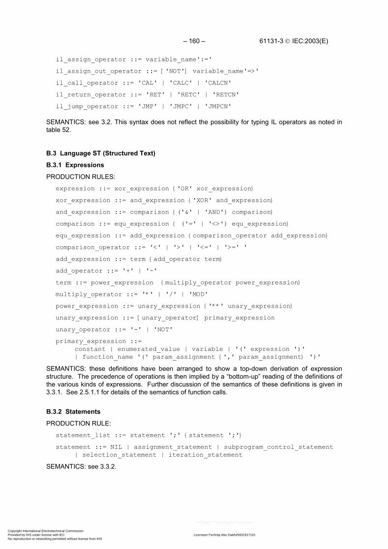
– 160 – 61131-3 IEC:2003(E)
il_assign_operator ::= variable_name':='
il_assign_out_operator ::= ['NOT'] variable_name'=>'
il_call_operator ::= 'CAL' | 'CALC' | 'CALCN'
il_return_operator ::= 'RET' | 'RETC' | 'RETCN'
il_jump_operator ::= 'JMP' | 'JMPC' | 'JMPCN'
SEMANTICS: see 3.2. This syntax does not reflect the possibility for typing IL operators as noted intable 52.
B.3 Language ST (Structured Text)
B.3.1 Expressions
PRODUCTION RULES:
expression ::= xor_expression {'OR' xor_expression}
xor_expression ::= and_expression {'XOR' and_expression}
and_expression ::= comparison {('&' | 'AND') comparison}
comparison ::= equ_expression { ('=' | '<>') equ_expression}
equ_expression ::= add_expression {comparison_operator add_expression}
comparison_operator ::= '<' | '>' | '<=' | '>=' '
add_expression ::= term {add_operator term}
add_operator ::= '+' | '-'
term ::= power_expression {multiply_operator power_expression}
multiply_operator ::= '*' | '/' | 'MOD'
power_expression ::= unary_expression {'**' unary_expression}
unary_expression ::= [unary_operator] primary_expression
unary_operator ::= '-' | 'NOT'
primary_expression ::=constant | enumerated_value | variable | '(' expression ')'| function_name '(' param_assignment {',' param_assignment} ')'
SEMANTICS: these definitions have been arranged to show a top-down derivation of expressionstructure. The precedence of operations is then implied by a “bottom-up” reading of the definitions ofthe various kinds of expressions. Further discussion of the semantics of these definitions is given in3.3.1. See 2.5.1.1 for details of the semantics of function calls.
B.3.2 Statements
PRODUCTION RULE:
statement_list ::= statement ';' {statement ';'}
statement ::= NIL | assignment_statement | subprogram_control_statement| selection_statement | iteration_statement
SEMANTICS: see 3.3.2.
Copyright International Electrotechnical Commission Provided by IHS under license with IEC Licensee=Technip Abu Dabhi/5931917101
Not for Resale, 02/12/2006 07:01:30 MSTNo reproduction or networking permitted without license from IHS
--``,`,`,,,``````,,``,,``,,,,`,-`-`,,`,,`,`,,`---

61131-3 IEC:2003(E) – 161 –
B.3.2.1 Assignment statements
PRODUCTION RULE:
assignment_statement ::= variable ':=' expression
SEMANTICS: see 3.3.2.1.
B.3.2.2 Subprogram control statements
PRODUCTION RULES:subprogram_control_statement ::= fb_invocation | 'RETURN'
fb_invocation ::= fb_name '(' [param_assignment {',' param_assignment}]')'
param_assignment ::= ([variable_name ':='] expression)| (['NOT'] variable_name '=>' variable)
SEMANTICS: see 3.3.2.2.
B.3.2.3 Selection statements
PRODUCTION RULES:selection_statement ::= if_statement | case_statement
if_statement ::='IF' expression 'THEN' statement_list {'ELSIF' expression 'THEN' statement_list} ['ELSE' statement_list]'END_IF'
case_statement ::='CASE' expression 'OF' case_element {case_element} ['ELSE' statement_list]'END_CASE'
case_element ::= case_list ':' statement_list
case_list ::= case_list_element {',' case_list_element}
case_list_element ::= subrange | signed_integer | enumerated_value
SEMANTICS: see 3.3.2.3.
B.3.2.4 Iteration statements
PRODUCTION RULES:iteration_statement ::=
for_statement | while_statement | repeat_statement | exit_statement
for_statement ::='FOR' control_variable ':=' for_list 'DO' statement_list 'END_FOR'
control_variable ::= identifier
for_list ::= expression 'TO' expression ['BY' expression]
while_statement ::= 'WHILE' expression 'DO' statement_list 'END_WHILE'
repeat_statement ::='REPEAT' statement_list 'UNTIL' expression 'END_REPEAT'
exit_statement ::= 'EXIT'
SEMANTICS: see 3.3.2.4.
Copyright International Electrotechnical Commission Provided by IHS under license with IEC Licensee=Technip Abu Dabhi/5931917101
Not for Resale, 02/12/2006 07:01:30 MSTNo reproduction or networking permitted without license from IHS
--``,`,`,,,``````,,``,,``,,,,`,-`-`,,`,,`,`,,`---

– 162 – 61131-3 IEC:2003(E)
ANNEX C(normative)
Delimiters and keywords
The usages of delimiters and keywords in this standard is summarized in tables C.1 and C.2. Nationalstandards organizations can publish tables of translations for the textual portions of the delimiterslisted in table C.1 and the keywords listed in table C.2.
Table C.1 - Delimiters
Delimiters Subclause Usage
Space 2.1.4 As specified in 2.1.4.
(* 2.1.5 Begin comment*) End comment
+ 2.2.1 Leading sign of decimal literal3.3.1 Addition operator
2.2.1 Leading sign of decimal literal- 2.2.3.2 Year-month-day separator
3.3.1 Subtraction, negation operator4.1.1 Horizontal line
# 2.2.1 Based number separator2.2.3 Time literal separator
. 2.2.1 Integer/fraction separator2.4.1.1 Hierarchical address separator2.4.1.2 Structure element separator2.5.2.1 Function block structure separator
e or E 2.2.1 Real exponent delimiter
' 2.2.2 Start and end of character string
$ 2.2.2 Start of special character in strings
2.2.3 - Time literal delimiters, including:T#, D, H, M, S, MS, DATE#, D#, TIME_OF_DAY#, TOD#, DATE_AND_TIME#, DT#
2.2.3.2 Time of day separator2.3.3.1 Type name/specification separator2.4.2 Variable/type separator2.6.2 Step name terminator
: 2.7 RESOURCE name/type separator2.7 PROGRAM name/type separator2.73.2.14.1.2
Access name/path/type separatorInstruction label terminatorNetwork label terminator
:=
2.3.3.12.7.13.3.2.1
Initialization operatorInput connection operatorAssignment operator
() 2.3.3.1 Enumeration list delimiters
Copyright International Electrotechnical Commission Provided by IHS under license with IEC Licensee=Technip Abu Dabhi/5931917101
Not for Resale, 02/12/2006 07:01:30 MSTNo reproduction or networking permitted without license from IHS
--``,`,`,,,``````,,``,,``,,,,`,-`-`,,`,,`,`,,`---

61131-3 IEC:2003(E) – 163 –
Table C.1 - Delimiters
Delimiters Subclause Usage() 2.3.3.1 Subrange delimiters[] 2.4.1.2 Array subscript delimiters[] 2.4.2 String length delimiters() 2.4.2 Multiple initialization() 3.2.2 Instruction List modifier/operator() 3.3.1 Function arguments() 3.3.1 Subexpression hierarchy() 3.3.2.2 Function block input list delimiters
2.3.3.1 Enumeration list separator2.3.3.2 Initial value separator2.4.1 Array subscript separator2.4.2 Declared variable separator
, 2.5.2.1 Function block initial value separator2.5.2.1 Function block input list separator3.2.1 Operand list separator3.3.1 Function argument list separator3.3.2.3 CASE value list separator
; 2.3.3.1 Type declaration separator3.3 Statement separator
.. 2.3.3.1 Subrange separator3.3.2.3 CASE range separator
% 2.4.1.1 Direct representation prefix
=> 2.7.1 Output connection operator
3.3.1 - Infix operators, including:**, NOT, *, /, MOD, +, -, <, >, <= >=, =, <>, &, AND, XOR, OR
| or ! 4.1.1 Vertical lines
Table C.2 - Keywords
Keywords Subclause
ACTION...END_ACTION 2.6.4.1
ARRAY...OF 2.3.3.1
AT 2.4.3
CASE...OF...ELSE...END_CASE 3.3.2.3
CONFIGURATION...END_CONFIGURATION 2.7.1
CONSTANT 2.4.3
Data type names 2.3
EN, ENO 2.5.1.2, 2.5.2.1a
EXIT 3.3.2.4
FALSE 2.2.1
F_EDGE 2.5.2.2
FOR...TO...BY...DO...END_FOR 3.3.2.4
Copyright International Electrotechnical Commission Provided by IHS under license with IEC Licensee=Technip Abu Dabhi/5931917101
Not for Resale, 02/12/2006 07:01:30 MSTNo reproduction or networking permitted without license from IHS
--``,`,`,,,``````,,``,,``,,,,`,-`-`,,`,,`,`,,`---

– 164 – 61131-3 IEC:2003(E)
Table C.2 - Keywords
Keywords Subclause
FUNCTION...END_FUNCTION 2.5.1.3
Function names 2.5.1
FUNCTION_BLOCK...END_FUNCTION_BLOCK 2.5.2.2
Function Block names 2.5.2
IF...THEN...ELSIF...ELSE...END_IF 3.3.2.3
INITIAL_STEP...END_STEP 2.6.2
NOT, MOD, AND, XOR, OR 3.3.1
PROGRAM...WITH... 2.7.1
PROGRAM...END_PROGRAM 2.5.3
R_EDGE 2.5.2.2
READ_ONLY, READ_WRITE 2.7.1
REPEAT...UNTIL...END_REPEAT 3.3.2.4
RESOURCE...ON...END_RESOURCE 2.7.1
RETAIN, NON_RETAIN 2.4.3
RETURN 3.3.2.2
STEP...END_STEP 2.6.2
STRUCT...END_STRUCT 2.3.3.1
TASK 2.7.2
TRANSITION...FROM...TO...END_TRANSITION 2.6.3
TRUE 2.2.1
TYPE...END_TYPE 2.3.3.1
VAR...END_VAR 2.4.3
VAR_INPUT...END_VAR 2.4.3
VAR_OUTPUT...END_VAR 2.4.3
VAR_IN_OUT...END_VAR 2.4.3
VAR_TEMP...END_VAR 2.4.3
VAR_EXTERNAL...END_VAR 2.4.3
VAR_ACCESS...END_VAR 2.7.1
VAR_CONFIG...END_VAR 2.7.1
VAR_GLOBAL...END_VAR 2.7.1
WHILE...DO...END_WHILE 3.3.2.4
WITH 2.7.1
Copyright International Electrotechnical Commission Provided by IHS under license with IEC Licensee=Technip Abu Dabhi/5931917101
Not for Resale, 02/12/2006 07:01:30 MSTNo reproduction or networking permitted without license from IHS
--``,`,`,,,``````,,``,,``,,,,`,-`-`,,`,,`,`,,`---

61131-3 IEC:2003(E) – 165 –
ANNEX D(normative)
Implementation-dependent parameters
The implementation-dependent parameters defined in this standard, and the primary reference clausefor each, are listed in table D.1.
NOTE Other implementation-dependent parameters such as the accuracy, precision andrepeatability of timing and execution control features may have significant effects on theportability of programs but are beyond the scope of this part of IEC 61131.
Table D.1 - Implementation-dependent parameters
Sublause Parameters
2.1.2 Maximum length of identifiers
2.1.5 Maximum comment length
2.1.6 Syntax and semantics of pragmas
2.2.2 Syntax and semantics for the use of the double-quote character when aparticular implementation supports feature 4 but not feature 2 of table 5.
2.3.1 Range of values and precision of representation for variables of type TIME,DATE, TIME_OF_DAY and DATE_AND_TIME
Precision of representation of seconds in types TIME, TIME_OF_DAY andDATE_AND_TIME
2.3.3.1 Maximum number of enumerated valuesMaximum number of array subscriptsMaximum array sizeMaximum number of structure elementsMaximum structure sizeMaximum range of subscript valuesMaximum number of levels of nested structures
2.3.3.2 Default maximum length of STRING and WSTRING variablesMaximum allowed length of STRING and WSTRING variables
2.4.1.1 Maximum number of hierarchical levelsLogical or physical mapping
2.4.2 Initialization of system inputs
2.4.3 Maximum number of variables per declarationEffect of using AT qualifier in declaration of function block instancesWarm start behavior if variable is declared as neither RETAIN nor NON_RETAIN
2.5 Information to determine execution times of program organization units
2.5.1.2 Values of outputs when ENO is FALSE
2.5.1.3 Maximum number of function specifications
2.5.1.5 Maximum number of inputs of extensible functions
2.5.1.5.1 Effects of type conversions on accuracyError conditions during type conversions
2.5.1.5.2 Accuracy of numerical functions
2.5.1.5.6 Effects of type conversions between time data types and other data types notdefined in table 30
Copyright International Electrotechnical Commission Provided by IHS under license with IEC Licensee=Technip Abu Dabhi/5931917101
Not for Resale, 02/12/2006 07:01:30 MSTNo reproduction or networking permitted without license from IHS
--``,`,`,,,``````,,``,,``,,,,`,-`-`,,`,,`,`,,`---

– 166 – 61131-3 IEC:2003(E)
Table D.1 - Implementation-dependent parameters
Sublause Parameters
2.5.2 Maximum number of function block specifications and instantiations
2.5.2.1a Function block input variable assignment when EN is FALSE
2.5.2.3.3 Pvmin, Pvmax of counters
2.5.2.3.4 Effect of a change in the value of a PT input during a timing operation
2.5.3 Program size limitations
2.6.2 Precision of step elapsed timeMaximum number of steps per SFC
2.6.3 Maximum number of transitions per SFC and per step
2.6.4.2 Maximum number of action blocks per step
2.6.4.5 Access to the functional equivalent of the Q or A outputs
2.6.5 Transition clearing timeMaximum width of diverge/converge constructs
2.7.1 Contents of RESOURCE libraries
2.7.1 Effect of using READ_WRITE access to function block outputs
2.7.2 Maximum number of tasksTask interval resolution
3.3.1 Maximum length of expressions
3.3.2 Maximum length of statements
3.3.2.3 Maximum number of CASE selections
3.3.2.4 Value of control variable upon termination of FOR loop
4.1.1 Restrictions on network topology
4.1.3 Evaluation order of feedback loops
Copyright International Electrotechnical Commission Provided by IHS under license with IEC Licensee=Technip Abu Dabhi/5931917101
Not for Resale, 02/12/2006 07:01:30 MSTNo reproduction or networking permitted without license from IHS
--``,`,`,,,``````,,``,,``,,,,`,-`-`,,`,,`,`,,`---
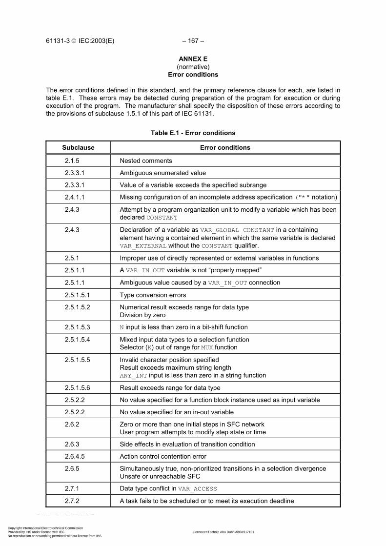
61131-3 IEC:2003(E) – 167 –
ANNEX E(normative)
Error conditions
The error conditions defined in this standard, and the primary reference clause for each, are listed intable E.1. These errors may be detected during preparation of the program for execution or duringexecution of the program. The manufacturer shall specify the disposition of these errors according tothe provisions of subclause 1.5.1 of this part of IEC 61131.
Table E.1 - Error conditions
Subclause Error conditions
2.1.5 Nested comments
2.3.3.1 Ambiguous enumerated value
2.3.3.1 Value of a variable exceeds the specified subrange
2.4.1.1 Missing configuration of an incomplete address specification ("*" notation)
2.4.3 Attempt by a program organization unit to modify a variable which has beendeclared CONSTANT
2.4.3 Declaration of a variable as VAR_GLOBAL CONSTANT in a containingelement having a contained element in which the same variable is declaredVAR_EXTERNAL without the CONSTANT qualifier.
2.5.1 Improper use of directly represented or external variables in functions
2.5.1.1 A VAR_IN_OUT variable is not “properly mapped”
2.5.1.1 Ambiguous value caused by a VAR_IN_OUT connection
2.5.1.5.1 Type conversion errors
2.5.1.5.2 Numerical result exceeds range for data typeDivision by zero
2.5.1.5.3 N input is less than zero in a bit-shift function
2.5.1.5.4 Mixed input data types to a selection functionSelector (K) out of range for MUX function
2.5.1.5.5 Invalid character position specifiedResult exceeds maximum string lengthANY_INT input is less than zero in a string function
2.5.1.5.6 Result exceeds range for data type
2.5.2.2 No value specified for a function block instance used as input variable
2.5.2.2 No value specified for an in-out variable
2.6.2 Zero or more than one initial steps in SFC networkUser program attempts to modify step state or time
2.6.3 Side effects in evaluation of transition condition
2.6.4.5 Action control contention error
2.6.5 Simultaneously true, non-prioritized transitions in a selection divergenceUnsafe or unreachable SFC
2.7.1 Data type conflict in VAR_ACCESS
2.7.2 A task fails to be scheduled or to meet its execution deadline
Copyright International Electrotechnical Commission Provided by IHS under license with IEC Licensee=Technip Abu Dabhi/5931917101
Not for Resale, 02/12/2006 07:01:30 MSTNo reproduction or networking permitted without license from IHS
--``,`,`,,,``````,,``,,``,,,,`,-`-`,,`,,`,`,,`---

– 168 – 61131-3 IEC:2003(E)
Table E.1 - Error conditions
Subclause Error conditions
3.2.2 Numerical result exceeds range for data typeCurrent result and operand not of same data type
3.3.1 Division by zeroNumerical result exceeds range for data typeInvalid data type for operation
3.3.2.1 Return from function without value assigned
3.3.2.4 Iteration fails to terminate
4.1.1 Same identifier used as connector label and element name
4.1.3 Uninitialized feedback variable
Copyright International Electrotechnical Commission Provided by IHS under license with IEC Licensee=Technip Abu Dabhi/5931917101
Not for Resale, 02/12/2006 07:01:30 MSTNo reproduction or networking permitted without license from IHS
--``,`,`,,,``````,,``,,``,,,,`,-`-`,,`,,`,`,,`---

61131-3 IEC:2003(E) – 169 –
ANNEX F(informative)Examples
F.1 Function WEIGH
Example function WEIGH provides the functions of BCD-to-binary conversion of a gross-weight inputfrom a scale, the binary integer subtraction of a tare weight which has been previously converted andstored in the memory of the programmable controller, and the conversion of the resulting net weightback to BCD form, for example, for an output display. The “EN” input is used to indicate that the scaleis ready to perform the weighing operation.
The “ENO” output indicates that an appropriate command exists (for example, from an operatorpushbutton), the scale is in proper condition for the weight to be read, and each function has a correctresult.
A textual form of the declaration of this function is:
FUNCTION WEIGH : WORD (* BCD encoded *) VAR_INPUT (* "EN" input is used to indicate "scale ready" *) weigh_command : BOOL; gross_weight : WORD ; (* BCD encoded *) tare_weight : INT ; END_VAR(* Function Body *)END_FUNCTION (* Implicit "ENO" *)
The body of function WEIGH in the IL language is:
LD weigh_command
JMPC WEIGH_NOW
ST ENO (* No weighing, 0 to "ENO" *)
RET
WEIGH_NOW: LD gross_weight
BCD_TO_INT
SUB tare_weight
INT_TO_BCD (* Return evaluated weight *)
ST WEIGH
The body of function WEIGH in the ST language is:
IF weigh_command THEN
WEIGH := INT_TO_BCD (BCD_TO_INT(gross_weight) - tare_weight);
END_IF ;
Copyright International Electrotechnical Commission Provided by IHS under license with IEC Licensee=Technip Abu Dabhi/5931917101
Not for Resale, 02/12/2006 07:01:30 MSTNo reproduction or networking permitted without license from IHS
--``,`,`,,,``````,,``,,``,,,,`,-`-`,,`,,`,`,,`---

– 170 – 61131-3 IEC:2003(E)
An equivalent graphical declaration of function WEIGH is:
+-------------------------+ | WEIGH | BOOL---|EN ENO|---BOOL BOOL---|weigh_command |---WORD WORD---|gross_weight | INT----|tare_weight | +-------------------------+
The function body in the LD language is:
| +--------+ +--------+ || | BCD_ | +-------+ | INT_ | || weigh_command | TO_INT | | SUB | | TO_BCD | ENO |+-------| |-----|EN ENO|--|EN ENO|---|EN ENO|----( )------+| | | | | | | || gross_weight--| |--| |---| |--WEIGH || +--------+ | | +--------+ || tare_weight---------------| | || +-------+ |
The function body in the FBD language is:
+--------+ +--------+ | BCD_ | +-------+ | INT_ | | TO_INT | | SUB | | TO_BCD |weigh_command---|EN ENO|---|EN ENO|---|EN ENO|---ENOgross_weight----| |---| |---| |--WEIGH +--------+ | | +--------+tare_weight------------------| | +-------+
F.2 Function block CMD_MONITOR
Example function block CMD_MONITOR illustrates the control of an operative unit which is capable ofresponding to a Boolean command (the CMD output) and returning a Boolean feedback signal (theFDBK input) indicating successful completion of the commanded action. The function block providesfor manual control via the MAN_CMD input, or automated control via the AUTO_CMD input,depending on the state of the AUTO_MODE input (0 or 1 respectively). Verification of the MAN_CMDinput is provided via the MAN_CMD_CHK input, which must be 0 in order to enable the MAN_CMDinput.
If confirmation of command completion is not received on the FDBK input within a predetermined timespecified by the T_CMD_MAX input, the command is cancelled and an alarm condition is signalled viathe ALRM output. The alarm condition may be cancelled by the ACK (acknowledge) input, enablingfurther operation of the command cycle.
Copyright International Electrotechnical Commission Provided by IHS under license with IEC Licensee=Technip Abu Dabhi/5931917101
Not for Resale, 02/12/2006 07:01:30 MSTNo reproduction or networking permitted without license from IHS
--``,`,`,,,``````,,``,,``,,,,`,-`-`,,`,,`,`,,`---
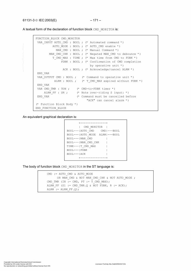
61131-3 IEC:2003(E) – 171 –
A textual form of the declaration of function block CMD_MONITOR is:
FUNCTION_BLOCK CMD_MONITOR VAR_INPUT AUTO_CMD : BOOL ; (* Automated command *) AUTO_MODE : BOOL ; (* AUTO_CMD enable *) MAN_CMD : BOOL ; (* Manual Command *) MAN_CMD_CHK : BOOL ; (* Negated MAN_CMD to debounce *) T_CMD_MAX : TIME ; (* Max time from CMD to FDBK *) FDBK : BOOL ; (* Confirmation of CMD completion by operative unit *) ACK : BOOL ; (* Acknowledge/cancel ALRM *) END_VAR VAR_OUTPUT CMD : BOOL ; (* Command to operative unit *) ALRM : BOOL ; (* T_CMD_MAX expired without FDBK *) END_VAR VAR CMD_TMR : TON ; (* CMD-to-FDBK timer *) ALRM_FF : SR ; (* Note over-riding S input: *) END_VAR (* Command must be cancelled before "ACK" can cancel alarm *)(* Function Block Body *)END_FUNCTION_BLOCK
An equivalent graphical declaration is:
+---------------+ | CMD_MONITOR |BOOL---|AUTO_CMD CMD|---BOOLBOOL---|AUTO_MODE ALRM|---BOOLBOOL---|MAN_CMD |BOOL---|MAN_CMD_CHK |TIME---|T_CMD_MAX |BOOL---|FDBK |BOOL---|ACK | +---------------+
The body of function block CMD_MONITOR in the ST language is:
CMD := AUTO_CMD & AUTO_MODE OR MAN_CMD & NOT MAN_CMD_CHK & NOT AUTO_MODE ; CMD_TMR (IN := CMD, PT := T_CMD_MAX); ALRM_FF (S1 := CMD_TMR.Q & NOT FDBK, R := ACK); ALRM := ALRM_FF.Q1;
Copyright International Electrotechnical Commission Provided by IHS under license with IEC Licensee=Technip Abu Dabhi/5931917101
Not for Resale, 02/12/2006 07:01:30 MSTNo reproduction or networking permitted without license from IHS
--``,`,`,,,``````,,``,,``,,,,`,-`-`,,`,,`,`,,`---
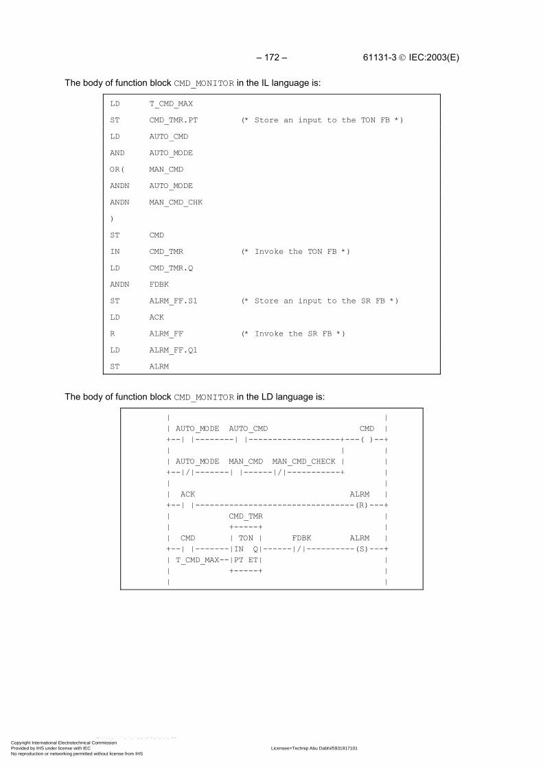
– 172 – 61131-3 IEC:2003(E)
The body of function block CMD_MONITOR in the IL language is:
LD T_CMD_MAX
ST CMD_TMR.PT (* Store an input to the TON FB *)
LD AUTO_CMD
AND AUTO_MODE
OR( MAN_CMD
ANDN AUTO_MODE
ANDN MAN_CMD_CHK
)
ST CMD
IN CMD_TMR (* Invoke the TON FB *)
LD CMD_TMR.Q
ANDN FDBK
ST ALRM_FF.S1 (* Store an input to the SR FB *)
LD ACK
R ALRM_FF (* Invoke the SR FB *)
LD ALRM_FF.Q1
ST ALRM
The body of function block CMD_MONITOR in the LD language is:
| | | AUTO_MODE AUTO_CMD CMD | +--| |--------| |-------------------+---( )--+ | | | | AUTO_MODE MAN_CMD MAN_CMD_CHECK | | +--|/|-------| |------|/|-----------+ | | | | ACK ALRM | +--| |---------------------------------(R)---+ | CMD_TMR | | +-----+ | | CMD | TON | FDBK ALRM | +--| |-------|IN Q|------|/|----------(S)---+ | T_CMD_MAX--|PT ET| | | +-----+ | | |
Copyright International Electrotechnical Commission Provided by IHS under license with IEC Licensee=Technip Abu Dabhi/5931917101
Not for Resale, 02/12/2006 07:01:30 MSTNo reproduction or networking permitted without license from IHS
--``,`,`,,,``````,,``,,``,,,,`,-`-`,,`,,`,`,,`---

61131-3 IEC:2003(E) – 173 –
The body of function block CMD_MONITOR in the FBD language is:
+-+ +---+AUTO_CMD------|&|----|>=1|--+-------------------------------CMDAUTO_MODE--+--| | +--| | | | +-+ | +---+ | | | | | +-+ | | CMD_TMR ALRM_FF +-O|&| | | +-----+ +-----+MAN_CMD-------| |-+ | | TON | +-+ | SR |MAN_CMD_CHK--O| | +--|IN Q|------|&|----|S1 Q1|--ALRM +-+ | | +--O| | +--|R |T_CMD_MAX----------------------|PT ET| | +-+ | +-----+ +-----+ | |FDBK------------------------------------+ |ACK---------------------------------------------+
F.3 Function block FWD_REV_MON
Example function block FWD_REV_MON illustrates the control of an operative unit capable of two-waypositioning action, for example, a motor-operated valve. Both automated and manual control modesare possible, with alarm capabilities provided for each direction of motion, as described for functionblock CMD_MONITOR above. In addition, contention between forward and reverse commands causesthe cancellation of both commands and signalling of an alarm condition. The Boolean OR of all alarmconditions is made available as a KLAXON output for operator signaling.
A graphical declaration of this function block is:
+----------------------+ | FWD_REV_MON |BOOL---|AUTO KLAXON|---BOOLBOOL---|ACK FWD_REV_ALRM|---BOOLBOOL---|AUTO_FWD FWD_CMD|---BOOLBOOL---|MAN_FWD FWD_ALRM|---BOOLBOOL---|MAN_FWD_CHK |TIME---|T_FWD_MAX |BOOL---|FWD_FDBK |BOOL---|AUTO_REV REV_CMD|---BOOLBOOL---|MAN_REV REV_ALRM|---BOOLBOOL---|MAN_REV_CHK |TIME---|T_REV_MAX |BOOL---|REV_FDBK | +----------------------+
Copyright International Electrotechnical Commission Provided by IHS under license with IEC Licensee=Technip Abu Dabhi/5931917101
Not for Resale, 02/12/2006 07:01:30 MSTNo reproduction or networking permitted without license from IHS
--``,`,`,,,``````,,``,,``,,,,`,-`-`,,`,,`,`,,`---

– 174 – 61131-3 IEC:2003(E)
A textual form of the declaration of function block FWD_REV_MON is:
FUNCTION_BLOCK FWD_REV_MONVAR_INPUT AUTO : BOOL ;(* Enable automated commands *) ACK : BOOL ; (* Acknowledge/cancel all alarms *) AUTO_FWD : BOOL ; (* Automated forward command *) MAN_FWD : BOOL ; (* Manual forward command *) MAN_FWD_CHK : BOOL ; (* Negated MAN_FWD for debouncing *) T_FWD_MAX : TIME ; (* Maximum time from FWD_CMD to FWD_FDBK *) FWD_FDBK : BOOL ; (* Confirmation of FWD_CMD completion *) (* by operative unit *) AUTO_REV : BOOL ; (* Automated reverse command *) MAN_REV : BOOL ; (* Manual reverse command *) MAN_REV_CHK : BOOL ; (* Negated MAN_REV for debouncing *) T_REV_MAX : TIME ; (* Maximum time from REV_CMD to REV_FDBK *) REV_FDBK : BOOL ; (* Confirmation of REV_CMD completion *)END_VAR (* by operative unit *)VAR_OUTPUT KLAXON : BOOL ; (* Any alarm active *) FWD_REV_ALRM : BOOL; (* Forward/reverse command conflict *) FWD_CMD : BOOL ; (* "Forward" command to operative unit *) FWD_ALRM : BOOL ; (* T_FWD_MAX expired without FWD_FDBK *) REV_CMD : BOOL ; (* "Reverse" command to operative unit *) REV_ALRM : BOOL ; (* T_REV_MAX expired without REV_FDBK *)END_VARVAR FWD_MON : CMD_MONITOR; (* "Forward" command monitor *) REV_MON : CMD_MONITOR; (* "Reverse" command monitor *) FWD_REV_FF : SR ; (* Forward/Reverse contention latch *)END_VAR(* Function Block body *)END_FUNCTION_BLOCK
The body of function block FWD_REV_MON can be written in the ST language as:
(* Evaluate internal function blocks *) FWD_MON (AUTO_MODE := AUTO, ACK := ACK, AUTO_CMD := AUTO_FWD, MAN_CMD := MAN_FWD, MAN_CMD_CHK := MAN_FWD_CHK, T_CMD_MAX := T_FWD_MAX, FDBK := FWD_FDBK); REV_MON (AUTO_MODE := AUTO, ACK := ACK, AUTO_CMD := AUTO_REV, MAN_CMD := MAN_REV, MAN_CMD_CHK := MAN_REV_CHK, T_CMD_MAX := T_REV_MAX, FDBK := REV_FDBK); FWD_REV_FF (S1 := FWD_MON.CMD & REV_MON.CMD, R := ACK);(* Transfer data to outputs *) FWD_REV_ALRM := FWD_REV_FF.Q1; FWD_CMD := FWD_MON.CMD & NOT FWD_REV_ALRM; FWD_ALRM := FWD_MON.ALRM; REV_CMD := REV_MON.CMD & NOT FWD_REV_ALRM; REV_ALRM := REV_MON.ALRM; KLAXON := FWD_ALRM OR REV_ALRM OR FWD_REV_ALRM;
Copyright International Electrotechnical Commission Provided by IHS under license with IEC Licensee=Technip Abu Dabhi/5931917101
Not for Resale, 02/12/2006 07:01:30 MSTNo reproduction or networking permitted without license from IHS
--``,`,`,,,``````,,``,,``,,,,`,-`-`,,`,,`,`,,`---

61131-3 IEC:2003(E) – 175 –
The body of function block FWD_REV_MON in the IL language is:
(* Evaluate internal function blocks *)CAL FWD_MON(
AUTO_MODE:= AUTO,ACK:= ACK,AUTO_CMD:= AUTO_FWD,MAN_CMD:= MAN_FWD,MAN_CMD_CHK:= MAN_FWD_CHK,T_CMD_MAX:= T_FWD_MAX,FDBK:= FWD_FDBK
)CAL REV_MON(
AUTO_MODE:= AUTO,ACK:= ACK,AUTO_CMD:= AUTO_REV,MAN_CMD:= MAN_REV,MAN_CMD_CHK:= MAN_REV_CHK,T_CMD_MAX:= T_REV_MAX,FDBK:= REV_FDBK
)CAL FWD_REV_FF(
S1:=(LD FWD_MON.CMDAND REV_MON.CMD),
R:= ACK,Q => FWD_REV_ALRM (* Contention alarm *)
)(* Transfer data to outputs *)LD FWD_MON.CMD (* "Forward" command and alarm *)
ANDN FWD_REV_ALRM
ST FWD_CMD
LD FWD_MON.ALRM
ST FWD_ALRM
LD REV_MON.CMD (* "Reverse" command and alarm *)
ANDN FWD_REV_ALRM
ST REV_CMD
LD REV_MON.ALRM
ST REV_ALRMOR FWD_ALRM (* OR all alarms *)OR FWD_REV_ALRM
ST KLAXON
Copyright International Electrotechnical Commission Provided by IHS under license with IEC Licensee=Technip Abu Dabhi/5931917101
Not for Resale, 02/12/2006 07:01:30 MSTNo reproduction or networking permitted without license from IHS
--``,`,`,,,``````,,``,,``,,,,`,-`-`,,`,,`,`,,`---

– 176 – 61131-3 IEC:2003(E)
The body of function block FWD_REV_MON in the FBD language is:
FWD_MON +---------------+ | CMD_MONITOR |AUTO_FWD----------|AUTO_CMD CMD|--+AUTO---------+----|AUTO_MODE ALRM|--|-------FWD_ALRMMAN_FWD------|----|MAN_CMD | |MAN_FWD_CHK--|----|MAN_CMD_CHK | |FWD_FDBK-----|----|FDBK | |ACK----------|-+--|ACK | |T_FWD_MAX----|-|--|T_CMD_MAX | | +---+ | | +---------------+ +--| & |-------------+ | | +--| | | | | REV_MON | +---+ | | | +---------------+ | | | | | CMD_MONITOR | | |AUTO_REV-----|-|--|AUTO_CMD CMD|--+ | +-|--|AUTO_MODE ALRM|---------REV_ALRM |MAN_REV--------|--|MAN_CMD | |MAN_REV_CHK----|--|MAN_CMD_CHK | |REV_FDBK-------|--|FDBK | | +--|ACK | |T_REV_MAX---------|T_CMD_MAX | | +---------------+ | +------------------------------------------------+ | FWD_REV_FF | +------+ | | SR | +-----|S1 Q1|--+----------------FWD_REV_ALRMACK------------|R | | +------+ | +-----+ +---| >=1 |------KLAXONFWD_MON.ALRM-------------|---| |REV_MON.ALRM-------------|---| | | +-----+ | | +---+ +--O| & |--------FWD_CMDFWD_MON.CMD--------------|---| | | +---+ | | +---+ +--O| & |--------REV_CMDREV_MON.CMD------------------| | +---+
Copyright International Electrotechnical Commission Provided by IHS under license with IEC Licensee=Technip Abu Dabhi/5931917101
Not for Resale, 02/12/2006 07:01:30 MSTNo reproduction or networking permitted without license from IHS
--``,`,`,,,``````,,``,,``,,,,`,-`-`,,`,,`,`,,`---

61131-3 IEC:2003(E) – 177 –
The body of function block FWD_REV_MON in the LD language is:
| FWD_MON || +---------------+ || AUTO_FWD | CMD_MONITOR | |+--| |---------|AUTO_CMD CMD| || AUTO | | FWD_ALRM |+--| |---------|AUTO_MODE ALRM|-------( )---+| MAN_FWD | | |+--| |---------|MAN_CMD | || MAN_FWD_CHK | | |+--| |---------|MAN_CMD_CHK | || FWD_FDBK | | |+--| |---------|FDBK | || ACK | | |+--| |---------|ACK | || | | || T_FWD_MAX---|T_CMD_MAX | || +---------------+ || || REV_MON || +---------------+ || AUTO_REV | CMD_MONITOR | |+--| |---------|AUTO_CMD CMD| || AUTO | | REV_ALRM |+--| |---------|AUTO_MODE ALRM|-------( )---+| MAN_REV | | |+--| |---------|MAN_CMD | || MAN_REV_CHK | | |+--| |---------|MAN_CMD_CHK | || REV_FDBK | | |+--| |---------|FDBK | || ACK | | |+--| |---------|ACK | || | | || T_REV_MAX---|T_CMD_MAX | || +---------------+ || || ACK FWD_REV_ALRM |+-----| |--------------------------(R)-------+| || FWD_MON.CMD REV_MON.CMD FWD_REV_ALRM |+-----| |-----------| |------------(S)-------+| || FWD_MON.CMD FWD_REV_ALRM FWD_CMD |+-----| |-----------|/|-------------( )------+| || REV_MON.CMD FWD_REV_ALRM REV_CMD |+-----| |-----------|/|-------------( )------+| |
| FWD_REV_ALRM KLAXON |+-----| |------+--------------------( )------+| | || FWD_ALRM | |+-----| |------+ || | || REV_ALRM | |+-----| |------+ || |
Copyright International Electrotechnical Commission Provided by IHS under license with IEC Licensee=Technip Abu Dabhi/5931917101
Not for Resale, 02/12/2006 07:01:30 MSTNo reproduction or networking permitted without license from IHS
--``,`,`,,,``````,,``,,``,,,,`,-`-`,,`,,`,`,,`---

– 178 – 61131-3 IEC:2003(E)
F.4 Function block STACK_INT
This function block provides a stack of up to 128 integers. The usual stack operations of PUSH andPOP are provided by edge-triggered Boolean inputs. An overriding reset (R1) input is provided; themaximum stack depth (N) is determined at the time of resetting. In addition to the top-of-stack data(OUT), Boolean outputs are provided indicating stack empty and stack overflow states.
A textual form of the declaration of this function block is:
FUNCTION_BLOCK STACK_INT VAR_INPUT PUSH, POP: BOOL R_EDGE; (* Basic stack operations *) R1 : BOOL ; (* Over-riding reset *) IN : INT ; (* Input to be pushed *) N : INT ; (* Maximum depth after reset *) END_VAR VAR_OUTPUT EMPTY : BOOL := 1 ; (* Stack empty *) OFLO : BOOL := 0 ; (* Stack overflow *) OUT : INT := 0 ; (* Top of stack data *) END_VAR VAR STK : ARRAY[0..127] OF INT; (* Internal stack *) NI : INT :=128 ; (* Storage for N upon reset *) PTR : INT := -1 ; (* Stack pointer *) END_VAR (* Function Block body *)END_FUNCTION_BLOCK
A graphical declaration of function block STACK_INT is:
+-----------+ | STACK_INT | BOOL--->PUSH EMPTY|---BOOL BOOL--->POP OFLO|---BOOL BOOL---|R1 OUT|---INT INT----|IN | INT----|N | +-----------+
(* Internal variable declarations *) VAR STK : ARRAY[0..127] OF INT ; (* Internal Stack *) NI : INT :=128 ; (* Storage for N upon Reset *) PTR : INT := -1 ; (* Stack Pointer *) END_VAR
Copyright International Electrotechnical Commission Provided by IHS under license with IEC Licensee=Technip Abu Dabhi/5931917101
Not for Resale, 02/12/2006 07:01:30 MSTNo reproduction or networking permitted without license from IHS
--``,`,`,,,``````,,``,,``,,,,`,-`-`,,`,,`,`,,`---

61131-3 IEC:2003(E) – 179 –
The body of function block STACK_INT in the ST language is:
IF R1 THEN OFLO := 0; EMPTY := 1; PTR := -1; NI := LIMIT (MN:=1,IN:=N,MX:=128); OUT := 0; ELSIF POP & NOT EMPTY THEN OFLO := 0; PTR := PTR-1; EMPTY := PTR < 0; IF EMPTY THEN OUT := 0; ELSE OUT := STK[PTR]; END_IF ; ELSIF PUSH & NOT OFLO THEN EMPTY := 0; PTR := PTR+1; OFLO := (PTR = NI); IF NOT OFLO THEN OUT := IN ; STK[PTR] := IN; ELSE OUT := 0; END_IF ; END_IF ;
The body of function block STACK_INT in the LD language is:
| || R1 |+---| |--->>RESET || || POP EMPTY |+--| |---|/|--->>POP_STK || || PUSH OFLO |+--| |---|/|--->>PUSH_STK || || |+--------------<RETURN> |
RESET:| +--------+ +--------+ +-------+ || | MOVE | | MOVE | | LIMIT | OFLO |+------|EN ENO|-----------|EN ENO|-----------|EN ENO|--+---(R)---+| 0---| |--OUT -1 --| |--PTR 128--|MX | | EMPTY || +--------+ +--------+ N--|IN | +---(S)---+| 1--|MN |--NI || +-------+ |+-----------------<RETURN>
Copyright International Electrotechnical Commission Provided by IHS under license with IEC Licensee=Technip Abu Dabhi/5931917101
Not for Resale, 02/12/2006 07:01:30 MSTNo reproduction or networking permitted without license from IHS
--``,`,`,,,``````,,``,,``,,,,`,-`-`,,`,,`,`,,`---

– 180 – 61131-3 IEC:2003(E)
POP_STK:| +--------+ +--------+ || | SUB | | LT | |+------------|EN ENO|-------|EN ENO| EMPTY || PTR--| |--PTR--| |----(S)---+| 1--| | 0--| | || +--------+ +--------+ || || +-------+ || | SEL | OFLO |+------------------|EN ENO|---------------(R)----+| EMPTY | | |+---| |------------|G |---OUT || STK[PTR]---|IN0 | || 0 ---|IN1 | || +-------+ |+--------------------------------<RETURN> |
PUSH_STK:| || +--------+ +--------+ || | ADD | | EQ | |+------------|EN ENO|-------|EN ENO| OFLO || PTR--| |--PTR--| |----(S)---+| 1--| | NI--| | || +--------+ +--------+ || || +------+ || OFLO | MOVE | |+---|/|-------|EN ENO|----------------------------+| IN---| |---STK[PTR] || +------+ || || +-------+ || | SEL | EMPTY |+-------------|EN ENO|--------------------(R)----+| OFLO | | |+---| |-------|G |---OUT || IN---|IN0 | || 0 ---|IN1 | || +-------+ |
Copyright International Electrotechnical Commission Provided by IHS under license with IEC Licensee=Technip Abu Dabhi/5931917101
Not for Resale, 02/12/2006 07:01:30 MSTNo reproduction or networking permitted without license from IHS
--``,`,`,,,``````,,``,,``,,,,`,-`-`,,`,,`,`,,`---
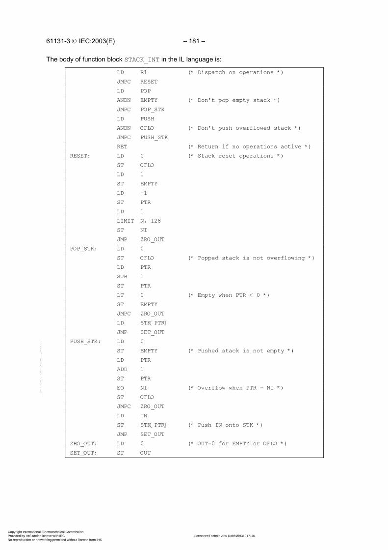
61131-3 IEC:2003(E) – 181 –
The body of function block STACK_INT in the IL language is:
LD R1 (* Dispatch on operations *)
JMPC RESET
LD POP
ANDN EMPTY (* Don't pop empty stack *)
JMPC POP_STK
LD PUSH
ANDN OFLO (* Don't push overflowed stack *)
JMPC PUSH_STK
RET (* Return if no operations active *)
RESET: LD 0 (* Stack reset operations *)
ST OFLO
LD 1
ST EMPTY
LD -1
ST PTR
LD 1
LIMIT N, 128
ST NI
JMP ZRO_OUT
POP_STK: LD 0
ST OFLO (* Popped stack is not overflowing *)
LD PTR
SUB 1
ST PTR
LT 0 (* Empty when PTR < 0 *)
ST EMPTY
JMPC ZRO_OUT
LD STK[PTR]
JMP SET_OUT
PUSH_STK: LD 0
ST EMPTY (* Pushed stack is not empty *)
LD PTR
ADD 1
ST PTR
EQ NI (* Overflow when PTR = NI *)
ST OFLO
JMPC ZRO_OUT
LD IN
ST STK[PTR] (* Push IN onto STK *)
JMP SET_OUT
ZRO_OUT: LD 0 (* OUT=0 for EMPTY or OFLO *)
SET_OUT: ST OUT
Copyright International Electrotechnical Commission Provided by IHS under license with IEC Licensee=Technip Abu Dabhi/5931917101
Not for Resale, 02/12/2006 07:01:30 MSTNo reproduction or networking permitted without license from IHS
--``,`,`,,,``````,,``,,``,,,,`,-`-`,,`,,`,`,,`---

– 182 – 61131-3 IEC:2003(E)
The body of function block STACK_INT in the FBD language is:
R1--+-->>RESET | +-+ +-----------------------------O|&|--<RETURN> | +-+ +--------------------O| | +--O|&| | +--O| | POP-----| |--+-->>POP_STK | +-+ EMPTY--O| | | +-+ | +-+ +-----------O|&|--+-->>PUSH_STK R1-----------------------O| | PUSH----------------------| | OFLO---------------------O| | +-+
RESET: +------+ +------+ +------+ | := | | := | | := |1 --|EN ENO|-------------|EN ENO|-----------|EN ENO|--+0 --| |---OUT -1 --| |---PTR 0--| |--|--OFLO +------+ +------+ +------+ | +---------------------------------------------+ | +------+ +-------+ | | := | | LIMIT | +--|EN ENO|---------------|EN ENO|--<RETURN> 1--| |---EMPTY 128--|MX | +------+ N--|IN |--NI 1--|MN | +-------+
POP_STK: +------+ +------+ +------+ +------+ | - | | < | | SEL | | := | 1----|EN ENO|-------|EN ENO|---------|EN ENO|------|EN ENO|--<RETURN> --PTR| |--PTR--| |--EMPTY--|G |-+ | | ----1| | 0 --| | +------|IN0 | | 0--| |--OFLO +------+ +------+ | +----|IN1 | | +------+ STK[PTR]—---------------------+ | +------+ | 0-------------------------------+ +---------------OUT
PUSH_STK: +------+ +------+ +------+ | := | | + | | = | 1--|EN ENO|-----------|EN ENO|-------|EN ENO|-- 0--| |--EMPTY 1--| |--PTR--|G |--+--OFLO +------+ +--| | NI---| | | PTR—---------------+ +------+ +------+ | +----------------------------+------------+ | +------+ | +-----+ | | := | | | SEL | +----|EN ENO| +---|G |-----OUT IN--+-----| |--STK[PTR] +-------|IN0 | | +------+ | 0---|IN1 | +-------------------------+ +-----+
Copyright International Electrotechnical Commission Provided by IHS under license with IEC Licensee=Technip Abu Dabhi/5931917101
Not for Resale, 02/12/2006 07:01:30 MSTNo reproduction or networking permitted without license from IHS
--``,`,`,,,``````,,``,,``,,,,`,-`-`,,`,,`,`,,`---

61131-3 IEC:2003(E) – 183 –
F.5 Function block MIX_2_BRIX
Function block MIX_2_BRIX is to control the mixing of two bricks of solid material, brought one at atime on a belt, with weighed quantities of two liquid components, A and B, as shown in figure F.1. A“Start” (ST) command, which may be manual or automatic, initiates a measurement and mixing cyclebeginning with simultaneous weighing and brick transport as follows:
- liquid A is weighed up to mark “a” of the weighing unit, then liquid B is weighed up to mark “b”,followed by filling of the mixer from weighing unit C;
- two bricks are transported by belt into the mixer.
The cycle ends with the mixer rotating and finally tipping after a predetermined time “t1”. Rotation ofthe mixer continues while it is emptying.
The scale reading “WC” is given as four BCD digits, and will be converted to type INT for internaloperations. It is assumed that the tare (empty weight) “z” has been previously determined.
MR
A
VA
B
VB
C
VC||| a ||||| b |||WC
MP0
MP1
S0
S1
MT
dtransit detector
belt motor
bricks
feed belt
tipping mixer
mixing motor
bidirectionaltipping motor
"Down" limit switch
"Up" limit switch
Weighing unit
Figure F.1 - Function block MIX_2_BRIX - physical modelIEC 2502/02
Copyright International Electrotechnical Commission Provided by IHS under license with IEC Licensee=Technip Abu Dabhi/5931917101
Not for Resale, 02/12/2006 07:01:30 MSTNo reproduction or networking permitted without license from IHS
--``,`,`,,,``````,,``,,``,,,,`,-`-`,,`,,`,`,,`---

– 184 – 61131-3 IEC:2003(E)
The textual form of the declaration of this function block is:
FUNCTION_BLOCK MIX_2_BRIX VAR_INPUT ST : BOOL ; (* "Start" command *) d : BOOL ; (* Transit detector *) S0 : BOOL ; (* "Mixer up" limit switch *) S1 : BOOL ; (* "Mixer down" limit switch *) WC : WORD; (* Current scale reading in BCD *) z : INT ; (* Tare (empty) weight *) WA : INT ; (* Desired weight of A *) WB : INT ; (* Desired weight of B *) t1 : TIME ; (* Mixing time *)END_VARVAR_OUTPUT DONE , VA , (* Valve "A" : 0 - close, 1 - open *) VB , (* Valve "B" : 0 - close, 1 - open *) VC , (* Valve "C" : 0 - close, 1 - open *) MT , (* Feed belt motor *) MR , (* Mixer rotation motor *) MP0 , (* Tipping motor "up" command *) MP1 : BOOL; (* Tipping motor "down" command *)END_VAR(* Function block body *)END_FUNCTION_BLOCK
A graphical declaration is:
+------------+ | MIX_2_BRIX |BOOL---|ST DONE|---BOOLBOOL---|d VA|---BOOLBOOL---|S0 VB|---BOOLBOOL---|S1 VC|---BOOLWORD---|WC MT|---BOOL INT---|z MR|---BOOL INT---|WA MP0|---BOOL INT---|WB MP1|---BOOLTIME---|t1 | +------------+
Copyright International Electrotechnical Commission Provided by IHS under license with IEC Licensee=Technip Abu Dabhi/5931917101
Not for Resale, 02/12/2006 07:01:30 MSTNo reproduction or networking permitted without license from IHS
--``,`,`,,,``````,,``,,``,,,,`,-`-`,,`,,`,`,,`---

61131-3 IEC:2003(E) – 185 –
The body of function block MIX_2_BRIX using graphical SFC elements with transition conditions inthe ST language is shown below.
+----------->------------+ | | | +====+====+ +---+------+ | || START ||---| N | DONE | | +====+====+ +---+------+ | | | + ST & S0 & BCD_TO_INT(WC) <= z | | | ===+===============+================+======= | | | | +----+----+ +---+----+ +----+---+ +---+----+ | | WEIGH_A |---| N | VA | | BRICK1 |---| S | MT | | +----+----+ +---+----+ +----+---+ +---+----+ | | | | + BCD_TO_INT(WC) >= WA+z + d | | | | +----+----+ +---+----+ +----+---+ | | WEIGH_B |---| N | VB | | DROP_1 | | +----+----+ +---+----+ +----+---+ | | | | + BCD_TO_INT(WC) >= WA+WB+z + NOT d | | | | +----+----+ +---+----+ +----+---+ | | FILL |---| N | VC | | BRICK2 | | +----+----+ +---+----+ +----+---+ | | + d | | +----+---+ +---+----+ | | | DROP_2 |---| R | MT | | | +----+---+ +---+----+ | | | | ====+===============+================+===== | | | + BCD_TO_INT(WC) <= z & NOT d | | | +--+--+ +---+----+ | | MIX |---| S | MR | | +--+--+ +---+----+ | | | + MIX.T >= t1 | | | +--+--+ +---+-----+----+ | | TIP |---| N | MP1 | S1 | | +--+--+ +---+-----+----+ | | | + S1 | | | +---+---+ +---+-----+----+ | | RAISE |---| R | MR | | | +---+---+ +---+-----+----+ | +S0 | N | MP0 | S0 | | | +---+-----+----+ +-----------<------------+
Copyright International Electrotechnical Commission Provided by IHS under license with IEC Licensee=Technip Abu Dabhi/5931917101
Not for Resale, 02/12/2006 07:01:30 MSTNo reproduction or networking permitted without license from IHS
--``,`,`,,,``````,,``,,``,,,,`,-`-`,,`,,`,`,,`---

– 186 – 61131-3 IEC:2003(E)
The body of function block MIX_2_BRIX in a textual SFC representation using ST language elementsis:
INITIAL_STEP START: DONE(N); END_STEP
TRANSITION FROM START TO (WEIGH_A, BRICK1) := ST & S0 & BCD_TO_INT(WC) <= z;END_TRANSITION
STEP WEIGH_A: VA(N); END_STEPTRANSITION FROM WEIGH_A TO WEIGH_B := BCD_TO_INT(WC) >= WA+z ;END_TRANSITION
STEP WEIGH_B: VB(N); END_STEPTRANSITION FROM WEIGH_B TO FILL := BCD_TO_INT(WC) >= WA+WB+z ;END_TRANSITION
STEP FILL: VC(N); END_STEPSTEP BRICK1: MT(S); END_STEPTRANSITION FROM BRICK1 TO DROP_1 := d ; END_TRANSITION
STEP DROP_1: END_STEPTRANSITION FROM DROP_1 TO BRICK2 := NOT d ; END_TRANSITION
STEP BRICK2: END_STEPTRANSITION FROM BRICK2 TO DROP_2 := d ; END_TRANSITION
STEP DROP_1: MT(R); END_STEP
TRANSITION FROM (FILL,DROP_2) TO MIX := BCD_TO_INT(WC) <= z & NOT d ;END_TRANSITION
STEP MIX: MR(S); END_STEPTRANSITION FROM MIX TO TIP := MIX.T >= t1 ; END_TRANSITION
STEP TIP: MP1(N); END_STEPTRANSITION FROM TIP TO RAISE := S1 ; END_TRANSITION
STEP RAISE: MR(R); MP0(N); END_STEPTRANSITION FROM RAISE TO START := S0 ; END_TRANSITION
F.6 Analog signal processing
The purpose of this portion of of this annex is to illustrate the application of the programminglanguages defined in this standard to accomplish the basic measurement and control functions ofprocess-computer aided automation. The blocks shown below are not restricted to analog signals;they may be used to process any variables of the appropriate types. Similarly, other functions andfunction blocks defined in this standard (for example, mathematical functions) can be used for theprocessing of variables which may appear as analog signals at the programmable controller's I/Oterminals.
These function blocks can be typed with respect to the input and output variables shown below asREAL (for example, XIN, XOUT) by appending the appropriate data type name, for example,LAG1_LREAL. The default data type for these variables is REAL.
These examples are given for illustrative purposes only. Manufacturers may have varyingimplementations of analog signal processing elements. The inclusion of these examples is notintended to preclude the standardization of such elements by the appropriate standards bodies.
Copyright International Electrotechnical Commission Provided by IHS under license with IEC Licensee=Technip Abu Dabhi/5931917101
Not for Resale, 02/12/2006 07:01:30 MSTNo reproduction or networking permitted without license from IHS
--``,`,`,,,``````,,``,,``,,,,`,-`-`,,`,,`,`,,`---
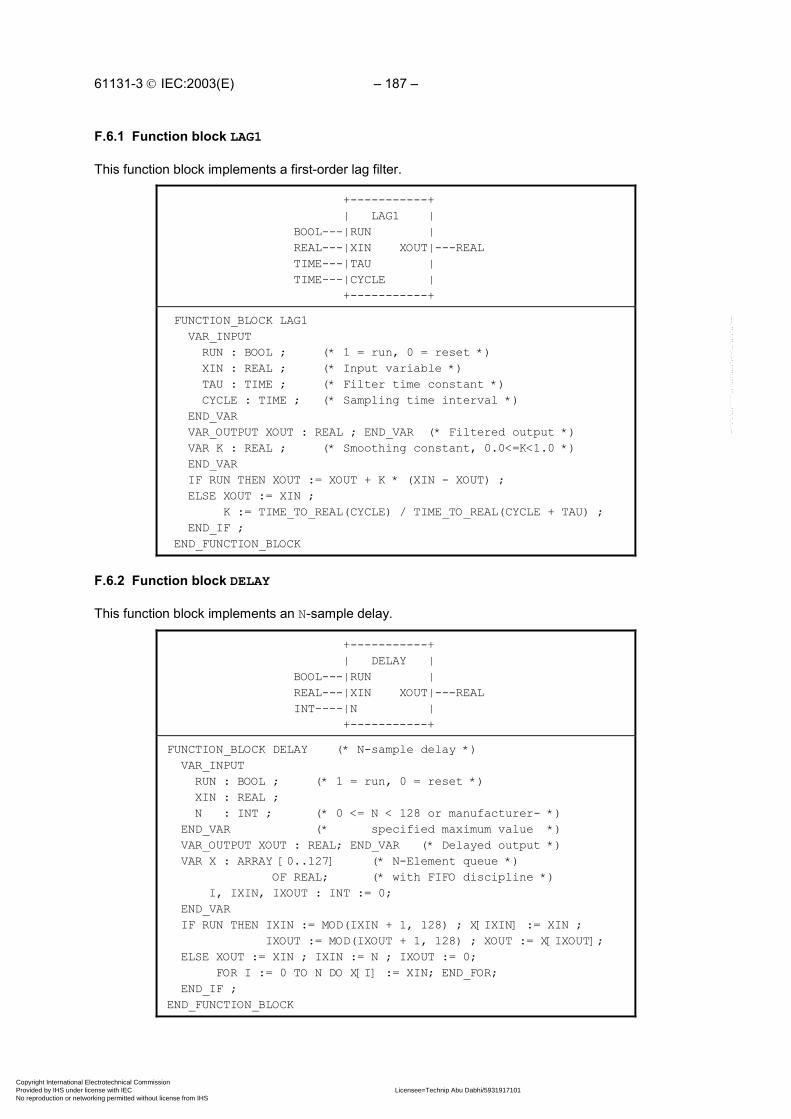
61131-3 IEC:2003(E) – 187 –
F.6.1 Function block LAG1
This function block implements a first-order lag filter.
+-----------+ | LAG1 | BOOL---|RUN | REAL---|XIN XOUT|---REAL TIME---|TAU | TIME---|CYCLE | +-----------+
FUNCTION_BLOCK LAG1 VAR_INPUT RUN : BOOL ; (* 1 = run, 0 = reset *) XIN : REAL ; (* Input variable *) TAU : TIME ; (* Filter time constant *) CYCLE : TIME ; (* Sampling time interval *) END_VAR VAR_OUTPUT XOUT : REAL ; END_VAR (* Filtered output *) VAR K : REAL ; (* Smoothing constant, 0.0<=K<1.0 *) END_VAR IF RUN THEN XOUT := XOUT + K * (XIN - XOUT) ; ELSE XOUT := XIN ; K := TIME_TO_REAL(CYCLE) / TIME_TO_REAL(CYCLE + TAU) ; END_IF ; END_FUNCTION_BLOCK
F.6.2 Function block DELAY
This function block implements an N-sample delay.
+-----------+ | DELAY | BOOL---|RUN | REAL---|XIN XOUT|---REAL INT----|N | +-----------+
FUNCTION_BLOCK DELAY (* N-sample delay *) VAR_INPUT RUN : BOOL ; (* 1 = run, 0 = reset *) XIN : REAL ; N : INT ; (* 0 <= N < 128 or manufacturer- *) END_VAR (* specified maximum value *) VAR_OUTPUT XOUT : REAL; END_VAR (* Delayed output *) VAR X : ARRAY [0..127] (* N-Element queue *) OF REAL; (* with FIFO discipline *) I, IXIN, IXOUT : INT := 0; END_VAR IF RUN THEN IXIN := MOD(IXIN + 1, 128) ; X[IXIN] := XIN ; IXOUT := MOD(IXOUT + 1, 128) ; XOUT := X[IXOUT]; ELSE XOUT := XIN ; IXIN := N ; IXOUT := 0; FOR I := 0 TO N DO X[I] := XIN; END_FOR; END_IF ;END_FUNCTION_BLOCK
Copyright International Electrotechnical Commission Provided by IHS under license with IEC Licensee=Technip Abu Dabhi/5931917101
Not for Resale, 02/12/2006 07:01:30 MSTNo reproduction or networking permitted without license from IHS
--``,`,`,,,``````,,``,,``,,,,`,-`-`,,`,,`,`,,`---

– 188 – 61131-3 IEC:2003(E)
F.6.3 Function block AVERAGE
This function block implements a running average over N samples.
+-----------+ | AVERAGE | BOOL---|RUN | REAL---|XIN XOUT|---REAL INT----|N | +-----------+
FUNCTION_BLOCK AVERAGE VAR_INPUT RUN : BOOL ; (* 1 = run, 0 = reset *) XIN : REAL ; (* Input variable *) N : INT ; (* 0 <= N < 128 or manufacturer- *) END_VAR (* specified maximum value *) VAR_OUTPUT XOUT : REAL ; END_VAR (* Averaged output *) VAR SUM : REAL := 0.0; (* Running sum *) FIFO : DELAY ; (* N-Element FIFO *) END_VAR SUM := SUM - FIFO.XOUT ; FIFO (RUN := RUN , XIN := XIN, N := N) ; SUM := SUM + FIFO.XOUT ; IF RUN THEN XOUT := SUM/N ; ELSE SUM := N*XIN ; XOUT := XIN ; END_IF ; END_FUNCTION_BLOCK
F.6.4 Function block INTEGRAL
This function block implements integration over time.
+-----------+ | INTEGRAL | BOOL---|RUN Q|---BOOL BOOL---|R1 | REAL---|XIN XOUT|---REAL REAL---|X0 | TIME---|CYCLE | +-----------+
FUNCTION_BLOCK INTEGRAL VAR_INPUT RUN : BOOL ; (* 1 = integrate, 0 = hold *) R1 : BOOL ; (* Overriding reset *) XIN : REAL ; (* Input variable *) X0 : REAL ; (* Initial value *) CYCLE : TIME ; (* Sampling period *) END_VAR VAR_OUTPUT Q : BOOL ; (* NOT R1 *) XOUT : REAL ; (* Integrated output *) END_VAR Q := NOT R1 ; IF R1 THEN XOUT := X0 ; ELSIF RUN THEN XOUT := XOUT + XIN * TIME_TO_REAL(CYCLE); END_IF ; END_FUNCTION_BLOCK
Copyright International Electrotechnical Commission Provided by IHS under license with IEC Licensee=Technip Abu Dabhi/5931917101
Not for Resale, 02/12/2006 07:01:30 MSTNo reproduction or networking permitted without license from IHS
--``,`,`,,,``````,,``,,``,,,,`,-`-`,,`,,`,`,,`---

61131-3 IEC:2003(E) – 189 –
F.6.5 Function block DERIVATIVE
This function block implements differentiation with respect to time.
+------------+ | DERIVATIVE | BOOL---|RUN | REAL---|XIN XOUT|---REAL TIME---|CYCLE | +------------+
FUNCTION_BLOCK DERIVATIVE VAR_INPUT RUN : BOOL ; (* 0 = reset *) XIN : REAL ; (* Input to be differentiated *) CYCLE : TIME ; (* Sampling period *) END_VAR VAR_OUTPUT XOUT : REAL ; (* Differentiated output *) END_VAR VAR X1, X2, X3 : REAL ; END_VAR IF RUN THEN XOUT := (3.0 * (XIN - X3) + X1 - X2) / (10.0 * TIME_TO_REAL(CYCLE)) ; X3 := X2 ; X2 := X1 ; X1 := XIN ; ELSE XOUT := 0.0; X1 := XIN ; X2 := XIN ; X3 := XIN ; END_IF ; END_FUNCTION_BLOCK
F.6.6 Function block HYSTERESIS
This function block implements Boolean hysteresis on the difference of REAL inputs.
+------------+ | HYSTERESIS | REAL---|XIN1 Q|---BOOL REAL---|XIN2 | REAL---|EPS | +------------+
FUNCTION_BLOCK HYSTERESIS (* Boolean hysteresis on difference *) (* of REAL inputs, XIN1 - XIN2 *) VAR_INPUT XIN1, XIN2, EPS : REAL; END_VAR VAR_OUTPUT Q : BOOL := 0; END_VAR IF Q THEN IF XIN1 < (XIN2 - EPS) THEN Q := 0; END_IF ; ELSIF XIN1 > (XIN2 + EPS) THEN Q := 1 ; END_IF ;END_FUNCTION_BLOCK
Copyright International Electrotechnical Commission Provided by IHS under license with IEC Licensee=Technip Abu Dabhi/5931917101
Not for Resale, 02/12/2006 07:01:30 MSTNo reproduction or networking permitted without license from IHS
--``,`,`,,,``````,,``,,``,,,,`,-`-`,,`,,`,`,,`---

– 190 – 61131-3 IEC:2003(E)
F.6.7 Function block LIMITS_ALARM
This function block implements a high/low limit alarm with hysteresis on both outputs.
+---------+ | LIMITS_ | | ALARM | (* High limit *) REAL--|H QH|--BOOL (* High flag *) (* Variable value *) REAL--|X Q|--BOOL (* Alarm output *) (* Lower limit *) REAL--|L QL|--BOOL (* Low flag *) (* Hysteresis *) REAL--|EPS | +---------+
(* Function block body in FBD language *) HIGH_ALARM +------------+ | HYSTERESIS | X------------------------+--|XIN1 Q|--+------------QH +---+ | | | | H----------------| - |------|XIN2 | | +---| | | | | | | +---+ | | | | +--------------|EPS | | +-----+ +---+ | | +------------+ +--| >=1 | EPS---| / |--+ | | |---Q 2.0---| | | | LOW_ALARM +--| | +---+ | | +------------+ | +-----+ | +---+ | | HYSTERESIS | | L----------------| + |------|XIN1 Q|--+------------QL | | | | | | +---| | +--|XIN2 | | +---+ | | +--------------|EPS | +------------+
F.6.8 Structure ANALOG_LIMITS
This data type implements the declarations of parameters for analog signal monitoring.
TYPE ANALOG_LIMITS : STRUCT HS : REAL ; (* High end of signal range *) HM : REAL ; (* High end of measurement range *) HA : REAL ; (* High alarm threshold *) HW : REAL ; (* High warning threshold *) NV : REAL ; (* Nominal value *) EPS : REAL ; (* Hysteresis *) LW : REAL ; (* Low warning threshold *) LA : REAL ; (* Low alarm threshold *) LM : REAL ; (* Low end of measurement range *) LS : REAL ; (* Low end of signal range *) END_STRUCT ; END_TYPE
Copyright International Electrotechnical Commission Provided by IHS under license with IEC Licensee=Technip Abu Dabhi/5931917101
Not for Resale, 02/12/2006 07:01:30 MSTNo reproduction or networking permitted without license from IHS
--``,`,`,,,``````,,``,,``,,,,`,-`-`,,`,,`,`,,`---

61131-3 IEC:2003(E) – 191 –
F.6.9 Function block ANALOG_MONITOR
This function block implements analog signal monitoring.
+---------+ | ANALOG_ | | MONITOR | REAL--|X SE|--BOOL (* Signal error *) ANALOG_LIMITS--|L ME|--BOOL (* Measurement error *) | ALRM|--BOOL (* Alarm *) | WARN|--BOOL (* Warning *) | QH|--BOOL (* 1 = Signal high *) +---------+
(* Function block body in FBD language *)
SIGNAL_ALARM MEAS_ALARM +--------------+ +--------------+ | LIMITS_ALARM | | LIMITS_ALARM | L.HS---|H Q|---SE L.HM---|H Q|---ME X------|X | X------|X | L.LS---|L | L.LM---|L | EPS----|EPS | EPS----|EPS | +--------------+ +--------------+
ALARM WARNING +--------------+ +--------------+ | LIMITS_ALARM | | LIMITS_ALARM | L.HA---|H Q|---ALRM L.HW---|H Q|---WARN X------|X | X---|X | L.LA---|L | L.LW---|L | EPS----|EPS | EPS---|EPS | +--------------+ +--------------+ +------+ SIGNAL_ALARM.QH---| >= 1 |---QH MEAS_ALARM.QH-----| | ALARM.QH----------| | WARNING.QH--------| | +------+
Copyright International Electrotechnical Commission Provided by IHS under license with IEC Licensee=Technip Abu Dabhi/5931917101
Not for Resale, 02/12/2006 07:01:30 MSTNo reproduction or networking permitted without license from IHS
--``,`,`,,,``````,,``,,``,,,,`,-`-`,,`,,`,`,,`---

– 192 – 61131-3 IEC:2003(E)
F.6.10 Function block PID
This function block implements Proportional + Integral + Derivative control action. The functionality isderived by functional composition of previously declared function blocks.
+-----------+ | PID | BOOL---|AUTO | REAL---|PV XOUT|---REAL REAL---|SP | REAL---|X0 | REAL---|KP | REAL---|TR | REAL---|TD | TIME---|CYCLE | +-----------+
FUNCTION_BLOCK PID VAR_INPUT AUTO : BOOL ; (* 0 - manual , 1 - automatic *) PV : REAL ; (* Process variable *) SP : REAL ; (* Set point *) X0 : REAL ; (* Manual output adjustment - *) (* Typically from transfer station *) KP : REAL ; (* Proportionality constant *) TR : REAL ; (* Reset time *) TD : REAL ; (* Derivative time constant *) CYCLE : TIME ; (* Sampling period *) END_VAR VAR_OUTPUT XOUT : REAL; END_VAR VAR ERROR : REAL ; (* PV - SP *) ITERM : INTEGRAL ; (* FB for integral term *) DTERM : DERIVATIVE ; (* FB for derivative term *) END_VAR ERROR := PV - SP ; (*** Adjust ITERM so that XOUT := X0 when AUTO = 0 ***) ITERM (RUN := AUTO, R1 := NOT AUTO, XIN := ERROR, X0 := TR * (X0 - ERROR), CYCLE := CYCLE) ; DTERM (RUN := AUTO, XIN := ERROR, CYCLE := CYCLE) ; XOUT := KP * (ERROR + ITERM.XOUT/TR + DTERM.XOUT*TD) ; END_FUNCTION_BLOCK
Copyright International Electrotechnical Commission Provided by IHS under license with IEC Licensee=Technip Abu Dabhi/5931917101
Not for Resale, 02/12/2006 07:01:30 MSTNo reproduction or networking permitted without license from IHS
--``,`,`,,,``````,,``,,``,,,,`,-`-`,,`,,`,`,,`---

61131-3 IEC:2003(E) – 193 –
F.6.11 Function block DIFFEQ
This function block implements a general difference equation.
+-----------+ | DIFFEQ | BOOL---|RUN | REAL---|XIN XOUT|---REAL ARRAY[1..127] OF REAL---|A | INT----|M | ARRAY[0..127] OF REAL---|B | INT----|N | +-----------+
FUNCTION_BLOCK DIFFEQ VAR_INPUT RUN : BOOL ; (* 1 = run, 0 = reset *) XIN : REAL ; A : ARRAY[1..127] OF REAL ; (* Input coefficients *) M : INT ; (* Length of input history *) B : ARRAY[0..127] OF REAL ; (* Output coefficients *) N : INT ; (* Length of output history *) END_VAR VAR_OUTPUT XOUT : REAL := 0.0 ; END_VAR VAR (* NOTE : Manufacturer may specify other array sizes *) XI : ARRAY [0..127] OF REAL ; (* Input history *) XO : ARRAY [0..127] OF REAL ; (* Output history *) I : INT ; END_VAR XO[0] := XOUT ; XI[0] := XIN ; XOUT := B[0] * XIN ; IF RUN THEN FOR I := M TO 1 BY -1 DO XOUT := XOUT + A[I] * XO[I] ; XO[I] := XO[I-1]; END_FOR; FOR I := N TO 1 BY -1 DO XOUT := XOUT + B[I] * XI[I] ; XI[I] := XI[I-1]; END_FOR; ELSE FOR I := 1 TO M DO XO[I] := 0.0; END_FOR; FOR I := 1 TO N DO XI[I] := 0.0; END_FOR; END_IF ; END_FUNCTION_BLOCK
Copyright International Electrotechnical Commission Provided by IHS under license with IEC Licensee=Technip Abu Dabhi/5931917101
Not for Resale, 02/12/2006 07:01:30 MSTNo reproduction or networking permitted without license from IHS
--``,`,`,,,``````,,``,,``,,,,`,-`-`,,`,,`,`,,`---

– 194 – 61131-3 IEC:2003(E)
F.6.12 Function block RAMP
This function block implements a time-based ramp.
+-----------+ | RAMP | BOOL---|RUN BUSY|---BOOL REAL---|X0 XOUT|---REAL REAL---|X1 | TIME---|TR | TIME---|CYCLE | +-----------+
FUNCTION_BLOCK RAMP VAR_INPUT RUN : BOOL ; (* 0 - track X0, 1 - ramp to/track X1 *) X0,X1 : REAL ; TR : TIME ; (* Ramp duration *) CYCLE : TIME ; (* Sampling period *) END_VAR VAR_OUTPUT BUSY : BOOL ; (* BUSY = 1 during ramping period *) XOUT : REAL := 0.0 ; END_VAR VAR XI : REAL ; (* Initial value *) T : TIME := T#0s; (* Elapsed time of ramp *) END_VAR BUSY := RUN ; IF RUN THEN IF T >= TR THEN BUSY := 0 ; XOUT := X1 ; ELSE XOUT := XI + (X1-XI) * TIME_TO_REAL(T) / TIME_TO_REAL(TR) ; T := T + CYCLE ; END_IF ; ELSE XOUT := X0 ; XI := X0 ; T := t#0s ; END_IF ; END_FUNCTION_BLOCK
Copyright International Electrotechnical Commission Provided by IHS under license with IEC Licensee=Technip Abu Dabhi/5931917101
Not for Resale, 02/12/2006 07:01:30 MSTNo reproduction or networking permitted without license from IHS
--``,`,`,,,``````,,``,,``,,,,`,-`-`,,`,,`,`,,`---

61131-3 IEC:2003(E) – 195 –
F.6.13 Function block TRANSFER
This function block implements a manual transfer station with bumpless transfer.
+-----------+ | TRANSFER | BOOL---|AUTO | REAL---|XIN XOUT|---REAL REAL---|FAST_RATE | REAL---|SLOW_RATE | BOOL---|FAST_UP | BOOL---|SLOW_UP | BOOL---|FAST_DOWN | BOOL---|SLOW_DOWN | TIME---|CYCLE | +-----------+
FUNCTION_BLOCK TRANSFER VAR_INPUT AUTO : BOOL ; (* 1 - track X0, 0 - ramp or hold *) XIN : REAL ; (* Typically from PID Function Block *) FAST_RATE, SLOW_RATE : REAL ; (* Up/down ramp slopes *) FAST_UP, SLOW_UP, (* Typically pushbuttons *) FAST_DOWN, SLOW_DOWN : BOOL; CYCLE : TIME ; (* Sampling period *) END_VAR VAR_OUTPUT XOUT : REAL ; END_VAR VAR XFER_RAMP : INTEGRAL ; RAMP_RATE : REAL ; END_VAR RAMP_RATE := 0.0 ; IF NOT AUTO THEN IF FAST_UP THEN RAMP_RATE := FAST_RATE; END_IF; IF SLOW_UP THEN RAMP_RATE := RAMP_RATE + SLOW_RATE; END_IF; IF FAST_DOWN THEN RAMP_RATE := RAMP_RATE - FAST_RATE; END_IF; IF SLOW_DOWN THEN RAMP_RATE := RAMP_RATE - SLOW_RATE; END_IF; END_IF ; XFER_RAMP (RUN := 1, CYCLE := CYCLE, R1 := AUTO, XIN := RAMP_RATE, X0 := XIN) ; XOUT := XFER_RAMP.XOUT;END_FUNCTION_BLOCK
F.7 Program GRAVEL
A control system is to be used to measure an operator-specified amount of gravel from a silo into anintermediate bin, and to convey the gravel after measurement from the bin into a truck.
The quantity of gravel to be transferred is specified via a thumbwheel with a range of 0 to 99 units.The amount of gravel in the bin is indicated on a digital display.
For safety reasons, visual and audible alarms must be raised immediately when the silo is empty. Thesignalling functions are to be implemented in the control program.
A graphic representation of the control problem is shown in figure F.2, while the variable declarationsfor the control program are given in figure F.3.
Copyright International Electrotechnical Commission Provided by IHS under license with IEC Licensee=Technip Abu Dabhi/5931917101
Not for Resale, 02/12/2006 07:01:30 MSTNo reproduction or networking permitted without license from IHS
--``,`,`,,,``````,,``,,``,,,,`,-`-`,,`,,`,`,,`---

– 196 – 61131-3 IEC:2003(E)
As shown in figure F.4, the operation of the system consists of a number of major states, beginningwith filling of the bin upon command from the FILL push button. After the bin is filled, the truckloading sequence begins upon command by the LOAD pushbutton when a truck is present on theramp. Loading consists of a “run-in” period for starting the conveyor, followed by dumping of the bincontents onto the conveyor. After the bin has emptied, the conveyor “runs out” for a predeterminedtime to assure that all gravel has been loaded to the truck. The loading sequence is stopped and re-initialized if the truck leaves the ramp or if the automatic control is stopped by the OFF push button.
Figure F.5 shows the OFF/ON sequence of automatic control states, as well as the generation ofdisplay blinking pulses and conveyor motor gating when the control is ON.
Bin level monitoring, operator interface and display functions are defined in figure F.6.
A textual version of the body of program GRAVEL is given in figure F.7, using the ST language withSFC elements.
An example configuration for program GRAVEL is given in figure F.8.
+---------+CONTROL PANEL:
| SILO | INDICATORS PUSH BUTTONS
| | ON
| | CONTROL SYSTEM ON OFF
| | TRUCK ON RAMP ACKNOWLEDGE
| | SILO EMPTY FILL
\ / CONVEYOR RUNNING LOAD
\ / LAMP TEST
| | "Silo empty" | o | limit switch 2-DIGIT BCD: | / | Silo valve DISPLAY THUMBWHEEL +---+ BIN LEVEL SET POINT
| BIN | | |
SIREN : SILO EMPTY
\ / "Bin empty" | o | limit switch | / | Bin valve +---+
"Truck on ramp" limit switch
Figure F.2 - Gravel measurement and loading system IEC 2503/02
Copyright International Electrotechnical Commission Provided by IHS under license with IEC Licensee=Technip Abu Dabhi/5931917101
Not for Resale, 02/12/2006 07:01:30 MSTNo reproduction or networking permitted without license from IHS
--``,`,`,,,``````,,``,,``,,,,`,-`-`,,`,,`,`,,`---

61131-3 IEC:2003(E) – 197 –
PROGRAM GRAVEL (* Gravel measurement and loading system *)
VAR_INPUT OFF_PB : BOOL ; ON_PB : BOOL ; FILL_PB : BOOL ; SIREN_ACK : BOOL ; LOAD_PB : BOOL ; (* Load truck from bin *) JOG_PB : BOOL ; LAMP_TEST : BOOL ; TRUCK_ON_RAMP : BOOL ; (* Optical sensor *) SILO_EMPTY_LS : BOOL ; BIN_EMPTY_LS : BOOL ; SETPOINT : BYTE ; (* 2-digit BCD *) END_VAR
VAR_OUTPUT CONTROL_LAMP : BOOL ; TRUCK_LAMP : BOOL ; SILO_EMPTY_LAMP : BOOL ; CONVEYOR_LAMP : BOOL ; CONVEYOR_MOTOR : BOOL ; SILO_VALVE : BOOL ; BIN_VALVE : BOOL ; SIREN : BOOL ; BIN_LEVEL : BYTE ; END_VAR
VAR BLINK_TIME : TIME; (* BLINK ON/OFF time *) PULSE_TIME : TIME; (* LEVEL_CTR increment interval *) RUNOUT_TIME: TIME; (* Conveyor running time after loading *) RUN_IN_TIME: TIME; (* Conveyor running time before loading *) SILENT_TIME: TIME; (* Siren silent time after SIREN_ACK *) OK_TO_RUN : BOOL; (* 1 = Conveyor is allowed to run *)
(* Function Blocks *) BLINK: TON; (* Blinker OFF period timer / ON output *) BLANK: TON; (* Blinker ON period timer / blanking pulse *) PULSE: TON; (* LEVEL_CTR pulse interval timer *) SIREN_FF: RS; SILENCE_TMR: TP; (* Siren silent period timer *) END_VAR
VAR RETAIN LEVEL_CTR : CTU ; END_VAR
(* Program body *)
END_PROGRAM
Figure F.3 - Declarations for program GRAVELIEC 2504/02
Copyright International Electrotechnical Commission Provided by IHS under license with IEC Licensee=Technip Abu Dabhi/5931917101
Not for Resale, 02/12/2006 07:01:30 MSTNo reproduction or networking permitted without license from IHS
--``,`,`,,,``````,,``,,``,,,,`,-`-`,,`,,`,`,,`---

– 198 – 61131-3 IEC:2003(E)
+--------------------->-----------------+| || +====+====+| || START ||| +====+====+| || + FILL_PB & CONTROL.X| || +-----+----+ +---+------------+| | FILL_BIN |---| N | SILO_VALVE || +-----+----+ +---+------------+| || +-----------------------------------*| | || + NOT FILL_PB OR NOT CONTROL.X + LEVEL_CTR.Q+---+ || +------------------>-------------+| | +-----+-----+| | | LOAD_WAIT || | +-----+-----+| | || | + LOAD_PB & OK_TO_RUN| | || | +----+---+| | | RUN_IN || | +----+---+| | || | +----------------------------*| | | || | + NOT OK_TO_RUN + RUN_IN.T >= RUN_IN_TIME| | | || +---+ +-----+----+ +---+-----------+| | | DUMP_BIN |---| N | BIN_VALVE || | +-----+----+ +---+-----------+| | || | +----------------------------*| | | || | + NOT OK_TO_RUN + BIN_EMPTY_LS| | | || +---+ +----+---+| | | RUNOUT || | +----+---+| | || | +----------------------------*| | | || | + NOT OK_TO_RUN + RUNOUT.T >= RUNOUT_TIME| +---+ |+---------------------------------------+
Figure F.4 - SFC of program GRAVEL bodyIEC 2505/02
Copyright International Electrotechnical Commission Provided by IHS under license with IEC Licensee=Technip Abu Dabhi/5931917101
Not for Resale, 02/12/2006 07:01:30 MSTNo reproduction or networking permitted without license from IHS
--``,`,`,,,``````,,``,,``,,,,`,-`-`,,`,,`,`,,`---

61131-3 IEC:2003(E) – 199 –
+---------+| || + OFF_PB| || +======+======+ +===========+ +---+----------------+| ||CONTROL_OFF|| || MONITOR ||---| N | MONITOR_ACTION || +======+======+ +===========+ +---+----------------+| || + ON_PB & NOT OFF_PB| || +---+---+ +---+----------------------------------+-----+| |CONTROL|--| N | CONTROL_ACTION | || +---+---+ +---+----------------------------------+-----+| | | +---------------------------------+ |+---------+ | | BLINK BLANK | | | | +-+ +-----+ +-----+ | | | +---O|&| | TON | | TON | | | |CONTROL.X--| |-----|IN Q|-----|IN Q|--+ | | +-+ +--|PT | +--|PT | | | | +-----+ | +-----+ | | BLINK_TIME--+-----------+ | | +-+ | |CONTROL.X------|&| | |TRUCK_ON_RAMP--| |---+---------OK_TO_RUN | | +-+ | | | | +-+ | | +-----+ +--|&|--CONVEYOR_MOTOR | |JOG_PB------| >=1 |-----| | | |RUN_IN.X----| | +-+ | |DUMP_BIN.X--| | | |RUNOUT.X----| | | | +-----+ | +--------------------------------------------+
Figure F.5 - Body of program GRAVEL (continued) -control state sequencing and monitoring
IEC 2506/02
Copyright International Electrotechnical Commission Provided by IHS under license with IEC Licensee=Technip Abu Dabhi/5931917101
Not for Resale, 02/12/2006 07:01:30 MSTNo reproduction or networking permitted without license from IHS
--``,`,`,,,``````,,``,,``,,,,`,-`-`,,`,,`,`,,`---

– 200 – 61131-3 IEC:2003(E)
MONITOR_ACTION
+---+CONVEYOR_MOTOR------------------------| & |------CONVEYOR_LAMPBLINK.Q-------------------------------| | +---+ +-----+CONTROL.X----------------------------| >=1 |---CONTROL_LAMPLAMP_TEST------------+---------------| | | +-----+ | +-----+ +---| >=1 |---------------TRUCK_LAMPTRUCK_ON_RAMP--------|---| | | +-----+ | +-----+ +---------------| >=1 |---SILO_EMPTY_LAMP +---+ | |BLINK.Q------------| & |-------------| |SILO_EMPTY_LS--+---| | +-----+ | +---+ SIREN_FF | +------+ | | RS | +-----------|S Q1|------------SIREN SILENCE_TMR | | +------+ | | | TP | | |SIREN_ACK-----|IN Q|-----|R1 |SILENT_TIME---|PT | +------+ +------+ LEVEL_CTR +-----+ | CTU |BIN_EMPTY_LS-----------------|R Q| +------------------+ | | | PULSE | | | | +-+ +-----+ | | | +---O|&| | TON | | | |FILL_BIN.X--| |--|IN Q|--+-->CU | +-+ | | | |PULSE_TIME-------|PT | | | +-----+ | | +------------+ | | +------------+SETPOINT----| BCD_TO_INT |---|PV CV|--| INT_TO_BCD |--BIN_LEVEL +------------+ +-----+ +------------+
Figure F.6 - Body of action MONITOR_ACTION in FBD languageIEC 2507/02
Copyright International Electrotechnical Commission Provided by IHS under license with IEC Licensee=Technip Abu Dabhi/5931917101
Not for Resale, 02/12/2006 07:01:30 MSTNo reproduction or networking permitted without license from IHS
--``,`,`,,,``````,,``,,``,,,,`,-`-`,,`,,`,`,,`---

61131-3 IEC:2003(E) – 201 –
Figure F.7 - Body of program GRAVEL in textual SFC representationusing ST language elements
(* Major operating states *) INITIAL_STEP START : END_STEP TRANSITION FROM START TO FILL_BIN := FILL_PB & CONTROL.X ; END_TRANSITION
STEP FILL_BIN: SILO_VALVE(N); END_STEP TRANSITION FROM FILL_BIN TO START := NOT FILL_PB OR NOT CONTROL.X ; END_TRANSITION TRANSITION FROM FILL_BIN TO LOAD_WAIT := LEVEL_CTR.Q ; END_TRANSITION
STEP LOAD_WAIT : END_STEP TRANSITION FROM LOAD_WAIT TO RUN_IN := LOAD_PB & OK_TO_RUN ; END_TRANSITION
STEP RUN_IN : END_STEP TRANSITION FROM RUN_IN TO LOAD_WAIT := NOT OK_TO_RUN ; END_TRANSITION TRANSITION FROM RUN_IN TO DUMP_BIN := RUN_IN.T > RUN_IN_TIME; END_TRANSITION
STEP DUMP_BIN: BIN_VALVE(N); END_STEP TRANSITION FROM DUMP_BIN TO LOAD_WAIT := NOT OK_TO_RUN ; END_TRANSITION TRANSITION FROM DUMP_BIN TO RUNOUT := BIN_EMPTY_LS ; END_TRANSITION
STEP RUNOUT : END_STEP TRANSITION FROM RUNOUT TO LOAD_WAIT := NOT OK_TO_RUN ; END_TRANSITION TRANSITION FROM RUNOUT TO START := RUNOUT.T >= RUNOUT_TIME ; END_TRANSITION
(* Control state sequencing *)INITIAL_STEP CONTROL_OFF: END_STEPTRANSITION FROM CONTROL_OFF TO CONTROL := ON_PB & NOT OFF_PB ; END_TRANSITION
STEP CONTROL: CONTROL_ACTION(N); END_STEPACTION CONTROL_ACTION: BLINK(EN:=CONTROL.X & NOT BLANK.Q, PT := BLINK_TIME) ; BLANK(EN:=BLINK.Q, PT := BLINK_TIME) ; OK_TO_RUN := CONTROL.X & TRUCK_ON_RAMP ; CONVEYOR_MOTOR := OK_TO_RUN & OR(JOG_PB, RUN_IN.X, DUMP_BIN.X, RUNOUT.X);END_ACTIONTRANSITION FROM CONTROL TO CONTROL_OFF := OFF_PB ;END_TRANSITION
Copyright International Electrotechnical Commission Provided by IHS under license with IEC Licensee=Technip Abu Dabhi/5931917101
Not for Resale, 02/12/2006 07:01:30 MSTNo reproduction or networking permitted without license from IHS
--``,`,`,,,``````,,``,,``,,,,`,-`-`,,`,,`,`,,`---

– 202 – 61131-3 IEC:2003(E)
Figure F.7 - Body of program GRAVEL in textual SFC representationusing ST language elements
(* Monitor Logic *)INITIAL_STEP MONITOR: MONITOR_ACTION(N); END_STEPACTION MONITOR_ACTION: CONVEYOR_LAMP := CONVEYOR_MOTOR & BLINK.Q ; CONTROL_LAMP := CONTROL.X OR LAMP_TEST ; TRUCK_LAMP := TRUCK_ON_RAMP OR LAMP_TEST ; SILO_EMPTY_LAMP := BLINK.Q & SILO_EMPTY_LS OR LAMP_TEST ; SILENCE_TMR(IN:=SIREN_ACK, PT:=SILENT_TIME) ; SIREN_FF(S:=SILO_EMPTY_LS, R1:=SILENCE_TMR.Q) ; SIREN := SIREN_FF.Q1 ; PULSE(IN:=FILL_BIN.X & NOT PULSE.Q, PT:=PULSE_TIME) ; LEVEL_CTR(R := BIN_EMPTY_LS, CU := PULSE.Q, PV := BCD_TO_INT(SETPOINT)) ; BIN_LEVEL := INT_TO_BCD(LEVEL_CTR.CV) ;END_ACTION
CONFIGURATION GRAVEL_CONTROL RESOURCE PROC1 ON PROC_TYPE_Y PROGRAM G : GRAVEL (* Inputs *) (OFF_PB := %I0.0 , ON_PB := %I0.1 , FILL_PB := %I0.2 , SIREN_ACK := %I0.3 , LOAD_PB := %I0.4 , JOG_PB := %I0.5 , LAMP_TEST := %I0.7 , TRUCK_ON_RAMP := %I1.4 , SILO_EMPTY_LS := %I1.5 , BIN_EMPTY_LS := %I1.6 , SETPOINT := %IB2 , (* Outputs *) CONTROL_LAMP => %Q4.0, TRUCK_LAMP => %Q4.2, SILO_EMPTY_LAMP => %Q4.3, CONVEYOR_LAMP => %Q5.3, CONVEYOR_MOTOR => %Q5.4, SILO_VALVE => %Q5.5, BIN_VALVE => %Q5.6, SIREN => %Q5.7, BIN_LEVEL => %B6) ; END_RESOURCE END_CONFIGURATION
Figure F.8 - Example configuration for program GRAVEL
IEC 2508/02
IEC 2509/02
Copyright International Electrotechnical Commission Provided by IHS under license with IEC Licensee=Technip Abu Dabhi/5931917101
Not for Resale, 02/12/2006 07:01:30 MSTNo reproduction or networking permitted without license from IHS
--``,`,`,,,``````,,``,,``,,,,`,-`-`,,`,,`,`,,`---

61131-3 IEC:2003(E) – 203 –
F.8 Program AGV
As illustrated in figure F.9, a program is to be devised to control an automatic guided vehicle (AGV).The AGV is to travel between two extreme positions, left (indicated by limit switch S3) and right(indicated by limit switch S4). The normal position of the AGV is on the left.
The AGV is to execute one cycle of left-to-right and return motion when the operator actuatespushbutton S1, and two cycles when the operator actuates pushbutton S2. It is also possible to passfrom a single to a double cycle by actuating pushbutton S2 during a single cycle. Finally, non-repeatlocking is to be provided if either S1 or S2 remains actuated.
Figure F.10 illustrates the graphical declaration of program AGV, while figure F.11 shows a typicalconfiguration for this program. Figure F.12 shows the AGV program body, consisting of a main controlsequence and a single-cycle control sequence.
LEFT_LS RIGHT_LSFWD_MOTORREV_MOTOR
1 Cycle 2 Cycles
AGV Control Panel
SINGLE_PB DOUBLE_PB
Figure F.9 - Physical model for program AGV
+----------------------+ | AGV |BOOL---|SINGLE_PB FWD_MOTOR|---BOOLBOOL---|DOUBLE_PB REV_MOTOR|---BOOLBOOL---|LEFT_LS |BOOL---|RIGHT_LS | +----------------------+
Figure F.10 - Graphical declaration of program AGV
IEC 2510/02
IEC 2511/02
Copyright International Electrotechnical Commission Provided by IHS under license with IEC Licensee=Technip Abu Dabhi/5931917101
Not for Resale, 02/12/2006 07:01:30 MSTNo reproduction or networking permitted without license from IHS
--``,`,`,,,``````,,``,,``,,,,`,-`-`,,`,,`,`,,`---

– 204 – 61131-3 IEC:2003(E)
CONFIGURATION AGV_CONTROL
RESOURCE AGV_PROC: SMALL_PC AGV_1
+--------------------+ | AGV | %IX1---|SINGLE_PB FWD_MOTOR|---%QX1 %IX2---|DOUBLE_PB REV_MOTOR|---%QX2 %IX3---|LEFT_LS | %IX4---|RIGHT_LS | +--------------------+
Figure F.11 - A graphical configuration of program AGV
+----------------------------+ ¦ ¦ ¦ +===+===+ (* Main sequence *) ¦ |¦START¦| ¦ +===+===+ ¦ ¦ ¦ +--------------------*----------+ | | | ¦ + READY.X & SINGLE_PB + READY.X & DOUBLE_PB | | | ¦ +--+---+ +-+-----+ +---+----+ +-+-----+ ¦ ¦SINGLE+-¦N¦CYCLE¦ ¦DOUBLE_1+--¦N¦CYCLE¦ ¦ +--+---+ +-+-----+ +---+----+ +-+-----+ | | | ¦ *---------+ + DONE.X ¦ ¦ + DONE.X & DOUBLE_PB ¦ ¦ ¦ +---------------------+ | | | ¦ ¦ +-----+-----+ ¦ + DONE.X & NOT DOUBLE_PB ¦DOUBLE_WAIT¦ ¦ ¦ +-----+-----+ | | | ¦ ¦ + READY.X | | | ¦ ¦ +---+----+ +-+-----+ ¦ ¦ ¦DOUBLE_2+--¦N¦CYCLE¦ ¦ ¦ +---+----+ +-+-----+ | | | ¦ ¦ + DONE.X | | | ¦ +---------------------+---------+ ¦ ¦ ¦ +----+-----+ ¦ ¦NON_REPEAT¦ ¦ +----+-----+ ¦ ¦ ¦ +NOT(SINGLE_PB OR DOUBLE_PB) ¦ ¦ +-----------------------------+
Figure F.12 - Body of program AGV
IEC 2512/02
Copyright International Electrotechnical Commission Provided by IHS under license with IEC Licensee=Technip Abu Dabhi/5931917101
Not for Resale, 02/12/2006 07:01:30 MSTNo reproduction or networking permitted without license from IHS
--``,`,`,,,``````,,``,,``,,,,`,-`-`,,`,,`,`,,`---

61131-3 IEC:2003(E) – 205 –
+-------+¦ |¦ +===+===+ (* Perform a single cycle *)¦ |¦READY¦|¦ +===+===+¦ |¦ + CYCLE¦ |¦ +---+---+ +-+---------+¦ ¦FORWARD+-¦N¦FWD_MOTOR¦¦ +---+---+ +-+---------+¦ |¦ + RIGHT_LS¦ |¦ +---+---+ +-+---------+¦ ¦REVERSE+-¦N¦REV_MOTOR¦¦ +---+---+ +-+---------+¦ |¦ + LEFT_LS¦ |¦ +--+-+¦ ¦DONE¦¦ +--+-+¦ |¦ + NOT CYCLE¦ |+-------+
Figure F.12 - Body of program AGV (continued)
IEC 2513/02
Copyright International Electrotechnical Commission Provided by IHS under license with IEC Licensee=Technip Abu Dabhi/5931917101
Not for Resale, 02/12/2006 07:01:30 MSTNo reproduction or networking permitted without license from IHS
--``,`,`,,,``````,,``,,``,,,,`,-`-`,,`,,`,`,,`---

– 206 – 61131-3 IEC:2003(E)
F.9 Use of enumerated data types
The following example illustrates the use of enumerated data types in ST CASE statements and inInstruction List. Suppose an enumerated data type has been defined by the following declaration:
TYPE SPEED: (SLOW, MEDIUM, FAST, VERY_FAST); END_TYPE
In addition, suppose an input and output of a function block type is declared by:
VAR_INPUT MOTOR_SPEED: SPEED; END_VARVAR_OUTPUT SPEED_OUT: SPEED; END_VAR
Then if the body of the function block type is defined in the ST language, a CASE statement such asthe following could be used:
CASE MOTOR_SPEED OF SLOW: (* speed it up *); MEDIUM: (* hold the current speed *); FAST: (* slow it down *);ELSE (* take special care *);END_CASE;
If the body of the function block type is defined in the IL language, the following instructions could beused:
LD SPEED#SLOW (* enumerated value qualified by data type *)ST SPEED_OUT
F.10 Function block RTC (Real Time Clock)
The RTC function block shown below sets the output CDT to the input value PDT at the next evaluationof the function block following a transition from 0 to 1 of the IN input. The CDT output of the RTCfunction block is undefined when the value of IN is 0.
Function block RTC (Real Time Clock)
PDT = Preset date and time, loaded on rising edge of INCDT = Current date and time, valid when IN=1Q = copy of IN
+-------+ | RTC |BOOL---|IN Q|---BOOLDT-----|PDT CDT|-----DT +-------+
F.11 Function block ALRM_INT
This function block type provides simple high and low level alarming for an input of type INT andillustrates the use of the VAR_OUTPUT declaration with functions. The function output is TRUE if a highor low threshold is exceeded, and separate outputs are provided for the high- or low-level alarmconditions.
Copyright International Electrotechnical Commission Provided by IHS under license with IEC Licensee=Technip Abu Dabhi/5931917101
Not for Resale, 02/12/2006 07:01:30 MSTNo reproduction or networking permitted without license from IHS
--``,`,`,,,``````,,``,,``,,,,`,-`-`,,`,,`,`,,`---

61131-3 IEC:2003(E) – 207 –
+----------+ | ALRM_INT |IN----|INT |---BOOLTHI---|INT HI|---BOOLTHL---|INT LO|---BOOL +----------+
+---+IN---| > |---+-----------------HITHI--| | | +----+ +---+ +--| OR |---ALRM_INT +---| | +---+ | +----+IN---| < |--+------------------LOTHL--| | +---+
FUNCTION ALRM_INT : BOOL
VAR_INPUT INT : IN ; INT : THI ; (* High threshold *) INT : TLO ; (* Low threshold *)END_VAR
VAR_OUTPUT HI: BOOL; (* High level alarm *) LO: BOOL; (* Low level alarm *)END_VAR
HI := IN > THI ;LO := IN < THL ;ALRM_INT := THI OR THL ;
END_FUNCTION
Copyright International Electrotechnical Commission Provided by IHS under license with IEC Licensee=Technip Abu Dabhi/5931917101
Not for Resale, 02/12/2006 07:01:30 MSTNo reproduction or networking permitted without license from IHS
--``,`,`,,,``````,,``,,``,,,,`,-`-`,,`,,`,`,,`---
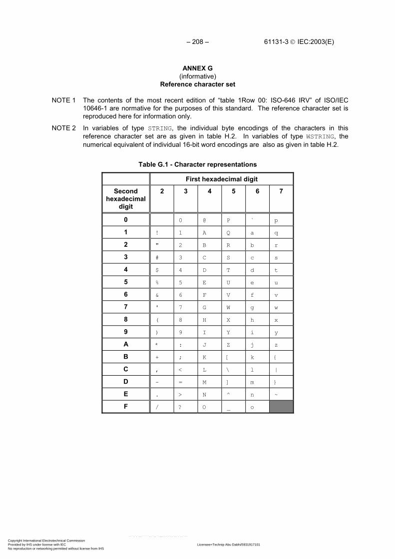
– 208 – 61131-3 IEC:2003(E)
ANNEX G(informative)
Reference character set
NOTE 1 The contents of the most recent edition of “table 1Row 00: ISO-646 IRV” of ISO/IEC10646-1 are normative for the purposes of this standard. The reference character set isreproduced here for information only.
NOTE 2 In variables of type STRING, the individual byte encodings of the characters in thisreference character set are as given in table H.2. In variables of type WSTRING, thenumerical equivalent of individual 16-bit word encodings are also as given in table H.2.
Table G.1 - Character representations
First hexadecimal digit
Secondhexadecimal
digit
2 3 4 5 6 7
0 0 @ P ` p
1 ! 1 A Q a q
2 " 2 B R b r
3 # 3 C S c s
4 $ 4 D T d t
5 % 5 E U e u
6 & 6 F V f v
7 ' 7 G W g w
8 ( 8 H X h x
9 ) 9 I Y i y
A * : J Z j z
B + ; K [ k {
C , < L \ l |
D - = M ] m }
E . > N ^ n ~
F / ? O _ o
Copyright International Electrotechnical Commission Provided by IHS under license with IEC Licensee=Technip Abu Dabhi/5931917101
Not for Resale, 02/12/2006 07:01:30 MSTNo reproduction or networking permitted without license from IHS
--``,`,`,,,``````,,``,,``,,,,`,-`-`,,`,,`,`,,`---

61131-3 IEC:2003(E) – 209 –
Table G.2 - Character encodings
dec hex Name dec hex Name
032 20 SPACE 080 50 LATIN CAPITAL LETTER P033 21 EXCLAMATION MARK 081 51 LATIN CAPITAL LETTER Q034 22 QUOTATION MARK 082 52 LATIN CAPITAL LETTER R035 23 NUMBER SIGN 083 53 LATIN CAPITAL LETTER S036 24 DOLLAR SIGN 084 54 LATIN CAPITAL LETTER T037 25 PERCENT SIGN 085 55 LATIN CAPITAL LETTER U038 26 AMPERSAND 086 56 LATIN CAPITAL LETTER V039 27 APOSTROPHE 087 57 LATIN CAPITAL LETTER W040 28 LEFT PARENTHESIS 088 58 LATIN CAPITAL LETTER X041 29 RIGHT PARENTHESIS 089 59 LATIN CAPITAL LETTER Y042 2A ASTERISK 090 5A LATIN CAPITAL LETTER Z043 2B PLUS SIGN 091 5B LEFT SQUARE BRACKET044 2C COMMA 092 5C REVERSE SOLIDUS045 2D HYPHEN-MINUS 093 5D RIGHT SQUARE BRACKET046 2E FULL STOP 094 5E CIRCUMFLEX ACCENT047 2F SOLIDUS 095 5F LOW LINE048 30 DIGIT ZERO 096 60 GRAVE ACCENT049 31 DIGIT ONE 097 61 LATIN SMALL LETTER A050 32 DIGIT TWO 098 62 LATIN SMALL LETTER B051 33 DIGIT THREE 099 63 LATIN SMALL LETTER C052 34 DIGIT FOUR 100 64 LATIN SMALL LETTER D053 35 DIGIT FIVE 101 65 LATIN SMALL LETTER E054 36 DIGIT SIX 102 66 LATIN SMALL LETTER F055 37 DIGIT SEVEN 103 67 LATIN SMALL LETTER G056 38 DIGIT EIGHT 104 68 LATIN SMALL LETTER H057 39 DIGIT NINE 105 69 LATIN SMALL LETTER I058 3A COLON 106 6A LATIN SMALL LETTER J059 3B SEMICOLON 107 6B LATIN SMALL LETTER K060 3C LESS-THAN SIGN 108 6C LATIN SMALL LETTER L061 3D EQUALS SIGN 109 6D LATIN SMALL LETTER M062 3E GREATER-THAN SIGN 110 6E LATIN SMALL LETTER N063 3F QUESTION MARK 111 6F LATIN SMALL LETTER O064 40 COMMERCIAL AT 112 70 LATIN SMALL LETTER P065 41 LATIN CAPITAL LETTER A 113 71 LATIN SMALL LETTER Q066 42 LATIN CAPITAL LETTER B 114 72 LATIN SMALL LETTER R067 43 LATIN CAPITAL LETTER C 115 73 LATIN SMALL LETTER S068 44 LATIN CAPITAL LETTER D 116 74 LATIN SMALL LETTER T069 45 LATIN CAPITAL LETTER E 117 75 LATIN SMALL LETTER U070 46 LATIN CAPITAL LETTER F 118 76 LATIN SMALL LETTER V071 47 LATIN CAPITAL LETTER G 119 77 LATIN SMALL LETTER W072 48 LATIN CAPITAL LETTER H 120 78 LATIN SMALL LETTER X073 49 LATIN CAPITAL LETTER I 121 79 LATIN SMALL LETTER Y074 4A LATIN CAPITAL LETTER J 122 7A LATIN SMALL LETTER Z075 4B LATIN CAPITAL LETTER K 123 7B LEFT CURLY BRACKET076 4C LATIN CAPITAL LETTER L 124 7C VERTICAL LINE077 4D LATIN CAPITAL LETTER M 125 7D RIGHT CURLY BRACKET078 4E LATIN CAPITAL LETTER N 126 7E TILDE079 4F LATIN CAPITAL LETTER O
Copyright International Electrotechnical Commission Provided by IHS under license with IEC Licensee=Technip Abu Dabhi/5931917101
Not for Resale, 02/12/2006 07:01:30 MSTNo reproduction or networking permitted without license from IHS
--``,`,`,,,``````,,``,,``,,,,`,-`-`,,`,,`,`,,`---

– 210 – 61131-3 IEC:2003(E)
Index
Primary references for delimiters and keywords are given in annex C.
absolute time, 28
access path, 108, 110communication, 16keyword, 39loading/deletion, 16programming, 18
action, 84, 89, 123control, 94qualifiers, 93
action block, 89, 91, 92, 95
active association, 95
active association, 95
activity flow, 135
aggregate, 10
argument, 66, 130, 133
arraydeclaration, 32, 42initialization, 33, 42location assignment, 42usage, 38, 134
assignment, 86FOR loop variable values, 134operator, 33, 86statement, 133
assignment, 47, 49, 51, 68
based number, 10, 25
bistable function block, 77
bit stringcomparison, 59data types, 30functions, 59initial value assignment, 42variable declaration, 41
bodyfunction, 51, 133function, 49, 68function block, 66program organization unit, 136
BooleanAND, in ladder diagrams, 140data type, 30default initial value, 34edge detection, 69, 78expression, 86, 130, 133, 134functions, 59functions, 95input, action control, 95
Copyright International Electrotechnical Commission Provided by IHS under license with IEC Licensee=Technip Abu Dabhi/5931917101
Not for Resale, 02/12/2006 07:01:30 MSTNo reproduction or networking permitted without license from IHS
--``,`,`,,,``````,,``,,``,,,,`,-`-`,,`,,`,`,,`---
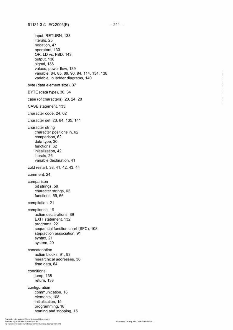
61131-3 IEC:2003(E) – 211 –
input, RETURN, 138literals, 25negation, 47operators, 130OR, LD vs. FBD, 143output, 138signal, 138values, power flow, 139variable, 84, 85, 89, 90, 94, 114, 134, 138variable, in ladder diagrams, 140
byte (data element size), 37
BYTE (data type), 30, 34
case (of characters), 23, 24, 28
CASE statement, 133
character code, 24, 62
character set, 23, 84, 135, 141
character stringcharacter positions in, 62comparison, 62data type, 30functions, 62initialization, 42literals, 26variable declaration, 41
cold restart, 38, 41, 42, 43, 44
comment, 24
comparisonbit strings, 59character strings, 62functions, 59, 66
compilation, 21
compliance, 19action declarations, 89EXIT statement, 132programs, 22sequential function chart (SFC), 108step/action association, 91syntax, 21system, 20
concatenationaction blocks, 91, 93hierarchical addresses, 36time data, 64
conditionaljump, 138return, 138
configurationcommunication, 16elements, 108initialization, 15programming, 18starting and stopping, 15
Copyright International Electrotechnical Commission Provided by IHS under license with IEC Licensee=Technip Abu Dabhi/5931917101
Not for Resale, 02/12/2006 07:01:30 MSTNo reproduction or networking permitted without license from IHS
--``,`,`,,,``````,,``,,``,,,,`,-`-`,,`,,`,`,,`---

– 212 – 61131-3 IEC:2003(E)
connection, 83
connector, 86, 88, 135, 136
contact, 140
counter, 78
data typecompliance, 21declaration, 32elementary, 30generic, 31, 53initialization, 33of an expression, 129of functions, 50of internal variables, 50programming, 18usage, 35
date and time, 81data types, 30default initial values, 34functions, 64literals, 29
decimal number (decimal literal), 25, 135
declaration, 18access paths, 110actions, 89, 94configurations, 108data types, 32function blocks, 66, 69functions, 50, 133programs, 83resources, 110tasks, 114variables, 39
default value, 52FOR increment, 134of data types, 33of variables, 38, 42task interval, 114
delimitercomments, 24LD network, 139network label, 135time literals, 28
direct representation, 36, 83, 111in programs, 83initial value assignment, 42variable declaration, 41
double word, 30size prefix, 37
durationdata type (TIME), 30literals, 28of action qualifiers, 93of step activity, 100
Copyright International Electrotechnical Commission Provided by IHS under license with IEC Licensee=Technip Abu Dabhi/5931917101
Not for Resale, 02/12/2006 07:01:30 MSTNo reproduction or networking permitted without license from IHS
--``,`,`,,,``````,,``,,``,,,,`,-`-`,,`,,`,`,,`---

61131-3 IEC:2003(E) – 213 –
edge detection, 69function blocks, 78
EN/ENO (enable) variables, 49, 50, 68
errors, 24, 32, 36, 40, 46, 47, 49, 52, 55, 56, 59, 61, 63, 64, 69, 85, 87, 95, 100, 114, 115, 124, 130,133, 134, 137, 167
documentation, 21handling, 21, 22reporting, 21
errors, 85, 100, 135
evaluationof assignment statements, 133of expressions, 129of function blocks, 115of functions, 58, 130, 133of language elements, 115of network elements, 136of networks, 66, 136, 141, 143of programs, 115of transitions, 100
executionof actions, 84of EXIT statements, 134of function blocks, 66, 78, 115of functions, 49of iteration statements, 134of loop elements, 137of programs, 138of selection statements, 133
execution control element, 84, 114, 136, 138, 141
extensions, 21, 37documentation, 21processing, 21usage, 22
extensions, 24
falling edge, 69, 71, 78
feedbackpath, 137variable, 137
FOR statement, 134
function, 45compliance, 21control statements, 133extensible, 55in LD language, 140overloaded, 53, 56, 59programming, 18return value, 133signal flow, 135typing, 53
function (procedure), 11
function block, 11, 14, 66action control, 94
Copyright International Electrotechnical Commission Provided by IHS under license with IEC Licensee=Technip Abu Dabhi/5931917101
Not for Resale, 02/12/2006 07:01:30 MSTNo reproduction or networking permitted without license from IHS
--``,`,`,,,``````,,``,,``,,,,`,-`-`,,`,,`,`,,`---
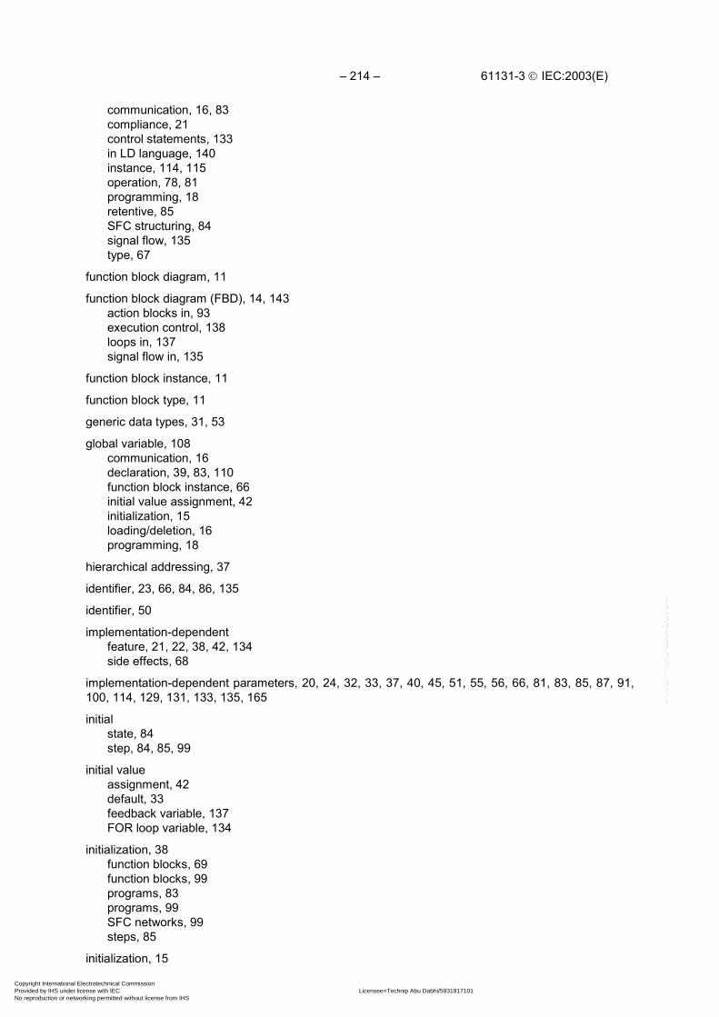
– 214 – 61131-3 IEC:2003(E)
communication, 16, 83compliance, 21control statements, 133in LD language, 140instance, 114, 115operation, 78, 81programming, 18retentive, 85SFC structuring, 84signal flow, 135type, 67
function block diagram, 11
function block diagram (FBD), 14, 143action blocks in, 93execution control, 138loops in, 137signal flow in, 135
function block instance, 11
function block type, 11
generic data types, 31, 53
global variable, 108communication, 16declaration, 39, 83, 110function block instance, 66initial value assignment, 42initialization, 15loading/deletion, 16programming, 18
hierarchical addressing, 37
identifier, 23, 66, 84, 86, 135
identifier, 50
implementation-dependentfeature, 21, 22, 38, 42, 134side effects, 68
implementation-dependent parameters, 20, 24, 32, 33, 37, 40, 45, 51, 55, 56, 66, 81, 83, 85, 87, 91,100, 114, 129, 131, 133, 135, 165
initialstate, 84step, 84, 85, 99
initial valueassignment, 42default, 33feedback variable, 137FOR loop variable, 134
initialization, 38function blocks, 69function blocks, 99programs, 83programs, 99SFC networks, 99steps, 85
initialization, 15
Copyright International Electrotechnical Commission Provided by IHS under license with IEC Licensee=Technip Abu Dabhi/5931917101
Not for Resale, 02/12/2006 07:01:30 MSTNo reproduction or networking permitted without license from IHS
--``,`,`,,,``````,,``,,``,,,,`,-`-`,,`,,`,`,,`---

61131-3 IEC:2003(E) – 215 –
inputdeclaration, 39, 50, 69dynamic, 69extensible, 55initialization, 38instance name, 66location prefix, 37negated, 47overloaded, 53program, 111string, 56variable, 67, 140variable, 83
input/outputvariable, 66
instancefunction block, 66, 67, 69, 70, 71, 114, 115name, 66, 67, 70, 71
instantiationaction control, 95function block, 83program, 83
instruction, 86, 89
integerdata types, 30, 134literal, 12, 25, 135
invocationby tasks, 114function block, 133function block, 66, 67, 69of actions, 84of functions, 129of non-PC language elements, 18recursive, 45return from, 138
iteration, 132, 134
keyword, 24Boolean literals, 26, 86data types, 30ELSE statement, 133FOR statement, 134function block declaration, 69function declaration, 50IF statement, 133program declaration, 83REPEAT statement, 134time literals, 28transition, 86variable declaration, 39WHILE statement, 134
labelconnector, 135network, 135, 136, 138
ladder diagram, 139
Copyright International Electrotechnical Commission Provided by IHS under license with IEC Licensee=Technip Abu Dabhi/5931917101
Not for Resale, 02/12/2006 07:01:30 MSTNo reproduction or networking permitted without license from IHS
--``,`,`,,,``````,,``,,``,,,,`,-`-`,,`,,`,`,,`---
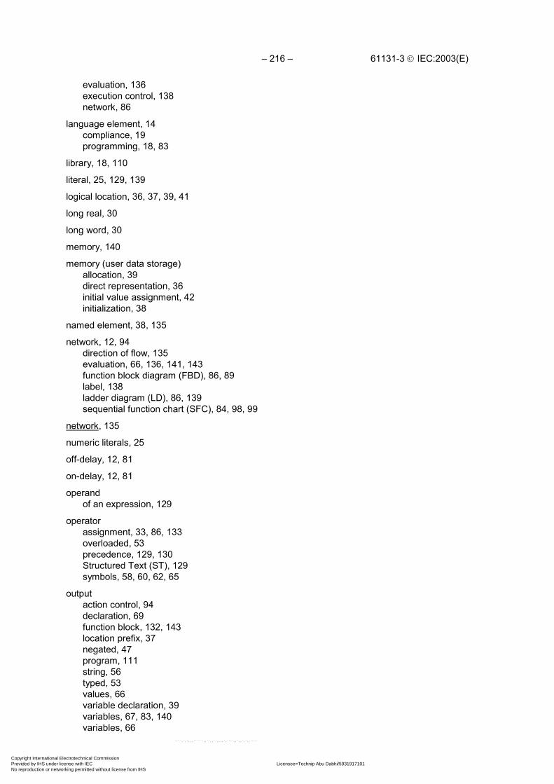
– 216 – 61131-3 IEC:2003(E)
evaluation, 136execution control, 138network, 86
language element, 14compliance, 19programming, 18, 83
library, 18, 110
literal, 25, 129, 139
logical location, 36, 37, 39, 41
long real, 30
long word, 30
memory, 140
memory (user data storage)allocation, 39direct representation, 36initial value assignment, 42initialization, 38
named element, 38, 135
network, 12, 94direction of flow, 135evaluation, 66, 136, 141, 143function block diagram (FBD), 86, 89label, 138ladder diagram (LD), 86, 139sequential function chart (SFC), 84, 98, 99
network, 135
numeric literals, 25
off-delay, 12, 81
on-delay, 12, 81
operandof an expression, 129
operatorassignment, 33, 86, 133overloaded, 53precedence, 129, 130Structured Text (ST), 129symbols, 58, 60, 62, 65
outputaction control, 94declaration, 69function block, 132, 143location prefix, 37negated, 47program, 111string, 56typed, 53values, 66variable declaration, 39variables, 67, 83, 140variables, 66
Copyright International Electrotechnical Commission Provided by IHS under license with IEC Licensee=Technip Abu Dabhi/5931917101
Not for Resale, 02/12/2006 07:01:30 MSTNo reproduction or networking permitted without license from IHS
--``,`,`,,,``````,,``,,``,,,,`,-`-`,,`,,`,`,,`---

61131-3 IEC:2003(E) – 217 –
overloading, 53of operators, 130
parentheses, 24, 33, 38, 43, 86, 130
power flow, 93, 135, 138, 139, 141
power rails, 139
power rails, 135, 138, 139
pre-emptive scheduling, 114
priorityof tasks, 114of transitions, 100
program, 14, 18, 83communication, 16compliance, 22declaration, 39, 83, 111declaration, 66, 75retentive, 85scheduling, 114SFC structuring, 84
program organization unit, 45, 66compliance, 20declaration, 39, 46initial state, 84jumps in, 138networks in, 135, 136, 141scheduling, 114SFC partitioning of, 84state, 84
programming, 18, 139
programming, 143
real literal, 25
resource, 14, 83communication, 17declaration, 110global variables in, 111initialization, 15, 38programming, 18starting and stopping, 15, 115
retentive datadeclaration, 39, 83in function blocks, 69in steps, 85initial value assignment, 42initialization, 38type assignment, 41
return, 132, 133, 138
rising edge, 69, 71, 78, 114, 206
rung, 139
rung, 89
scopeglobal, 111
Copyright International Electrotechnical Commission Provided by IHS under license with IEC Licensee=Technip Abu Dabhi/5931917101
Not for Resale, 02/12/2006 07:01:30 MSTNo reproduction or networking permitted without license from IHS
--``,`,`,,,``````,,``,,``,,,,`,-`-`,,`,,`,`,,`---

– 218 – 61131-3 IEC:2003(E)
of actions, 89of declarations, 40of function block instances, 66of networks, 135of steps, 84of transitions, 87
selectionfunctions, 59, 66statements, 133
semanticsStructured Text (ST), 129
semigraphic representation, 69, 114, 135, 136
sequential function chart (SFC)activity flow, 135compliance, 108convergence, simultaneous, 100divergence, selection, 100divergence, simultaneous, 100elements, 14, 84elements, 123, 134, 135elements, compatibility of, 107errors, 100evolution, 99programming, 18
signal flow, 135, 143
single data element, 35, 36
step, 84action association, 91activation, 100activation, 99active, 84, 85, 100active, 95deactivation, 84, 91, 99duration, 100elapsed time, 84, 85flag, 84, 85inactive, 84initial, 84, 85, 99initialization, 85retentive, 85state, 84, 99, 100, 105
structured data type, 67declaration, 32initialization, 33usage, 35
structured variable, 38assignment, 133declaration, 42initialization, 42step elements, 84
subscripting, 38array initialization, 43
symbolic representation, 36, 41
Copyright International Electrotechnical Commission Provided by IHS under license with IEC Licensee=Technip Abu Dabhi/5931917101
Not for Resale, 02/12/2006 07:01:30 MSTNo reproduction or networking permitted without license from IHS
--``,`,`,,,``````,,``,,``,,,,`,-`-`,,`,,`,`,,`---

61131-3 IEC:2003(E) – 219 –
synchronizationinterprocess, 134of function blocks, 114
syntax, 14documentation, 21step/transition, 100
task, 14, 114declaration, 110programming, 18
TIME data type, 30, 84, 85, 93default initial value, 34function blocks, 81functions, 64
time literal, 28
time of daydata types, 30default initial value, 34functions, 64keywords, 29literals, 28
timer, 81
transition, 84, 86clearing, 99, 100clearing time, 100condition, 84, 86, 89, 99enabled, 99evaluation, 100priority, 100symbol, 99
type conversionfunctions, 53, 55
typed literals, 26
underline character, 23, 25, 53
unsigned integer, 135data types, 30
variable, 36declaration, 50, 69usage, 35
WAIT function, 89, 134
warm restart, 38
white space, 24
wired OR, 143
____________
Copyright International Electrotechnical Commission Provided by IHS under license with IEC Licensee=Technip Abu Dabhi/5931917101
Not for Resale, 02/12/2006 07:01:30 MSTNo reproduction or networking permitted without license from IHS
--``,`,`,,,``````,,``,,``,,,,`,-`-`,,`,,`,`,,`---

Copyright International Electrotechnical Commission Provided by IHS under license with IEC Licensee=Technip Abu Dabhi/5931917101
Not for Resale, 02/12/2006 07:01:30 MSTNo reproduction or networking permitted without license from IHS
--``,`,`,,,``````,,``,,``,,,,`,-`-`,,`,,`,`,,`---

Standards Survey
The IEC would like to offer you the best quality standards possible. To make sure that wecontinue to meet your needs, your feedback is essential. Would you please take a minuteto answer the questions overleaf and fax them to us at +41 22 919 03 00 or mail them tothe address below. Thank you!
Customer Service Centre (CSC)
International Electrotechnical Commission3, rue de Varembé1211 Genève 20Switzerland
or
Fax to: IEC/CSC at +41 22 919 03 00
Thank you for your contribution to the standards-making process.
Non affrancareNo stamp required
Nicht frankierenNe pas affranchir
A Prioritaire
RÉPONSE PAYÉE
SUISSE
Customer Service Centre (CSC)International Electrotechnical Commission3, rue de Varembé1211 GENEVA 20Switzerland
Copyright International Electrotechnical Commission Provided by IHS under license with IEC Licensee=Technip Abu Dabhi/5931917101
Not for Resale, 02/12/2006 07:01:30 MSTNo reproduction or networking permitted without license from IHS
--``,`,`,,,``````,,``,,``,,,,`,-`-`,,`,,`,`,,`---

Q1 Please report on ONE STANDARD andONE STANDARD ONLY . Enter the exactnumber of the standard: (e.g. 60601-1-1)
.............................................................
Q2 Please tell us in what capacity(ies) youbought the standard (tick all that apply).I am the/a:
purchasing agent R
librarian R
researcher R
design engineer R
safety engineer R
testing engineer R
marketing specialist R
other.....................................................
Q3 I work for/in/as a:(tick all that apply)
manufacturing R
consultant R
government R
test/certification facility R
public utility R
education R
military R
other.....................................................
Q4 This standard will be used for:(tick all that apply)
general reference R
product research R
product design/development R
specifications R
tenders R
quality assessment R
certification R
technical documentation R
thesis R
manufacturing R
other.....................................................
Q5 This standard meets my needs:(tick one)
not at all R
nearly R
fairly well R
exactly R
Q6 If you ticked NOT AT ALL in Question 5the reason is: (tick all that apply)
standard is out of date R
standard is incomplete R
standard is too academic R
standard is too superficial R
title is misleading R
I made the wrong choice R
other ....................................................
Q7 Please assess the standard in thefollowing categories, usingthe numbers:(1) unacceptable,(2) below average,(3) average,(4) above average,(5) exceptional,(6) not applicable
timeliness .............................................quality of writing....................................technical contents.................................logic of arrangement of contents ..........tables, charts, graphs, figures ...............other ....................................................
Q8 I read/use the: (tick one)
French text only R
English text only R
both English and French texts R
Q9 Please share any comment on anyaspect of the IEC that you would likeus to know:
............................................................
............................................................
............................................................
............................................................
............................................................
............................................................
............................................................
............................................................
............................................................
............................................................
............................................................
............................................................
Copyright International Electrotechnical Commission Provided by IHS under license with IEC Licensee=Technip Abu Dabhi/5931917101
Not for Resale, 02/12/2006 07:01:30 MSTNo reproduction or networking permitted without license from IHS
--``,`,`,,,``````,,``,,``,,,,`,-`-`,,`,,`,`,,`---

Copyright International Electrotechnical Commission Provided by IHS under license with IEC Licensee=Technip Abu Dabhi/5931917101
Not for Resale, 02/12/2006 07:01:30 MSTNo reproduction or networking permitted without license from IHS
--``,`,`,,,``````,,``,,``,,,,`,-`-`,,`,,`,`,,`---

ISBN 2-8318-6653-7
-:HSMINB=][[ZX[:ICS 25.040; 35.240.50
Typeset and printed by the IEC Central Office GENEVA, SWITZERLAND
Copyright International Electrotechnical Commission Provided by IHS under license with IEC Licensee=Technip Abu Dabhi/5931917101
Not for Resale, 02/12/2006 07:01:30 MSTNo reproduction or networking permitted without license from IHS
--``,`,`,,,``````,,``,,``,,,,`,-`-`,,`,,`,`,,`---