international journal of advanced research in issn: …ijarets.org/publication/30/ijarets...
TRANSCRIPT

International Journal of Advanced Research in ISSN: 2394-2819 E Engineering Technology & Science December- 2016 Volume-3, Issue-12 Email: [email protected] www.ijarets.org
[email protected] Page 31
MICROWAVES THERMAL SYNTHESIS AND CHARACTERIZATION OF MANGANESE-
DOPED ZINC-OXIDE NANOPARTICLES
Sunil Kumar Arun Kumar Sharma
Department of Physics (Applies Sciences), Department of Physics (Applies Sciences),
IIMT College of Engineering IIMT College of Engineering
Greater Noida Greater Noida
P. K. Sharma
Department of Physics (Applies Sciences),
IIMT College of Engineering
Greater Noida
ABSTRACT: Mn-doped zinc oxide nano-paricles were prepared by using the microwave thermal
synthesis (MSS) technique. The nanoparticles were produced from a solution of zinc acetate dihydrate
and manganese (II) acetate tetra hydrate using ethylene glycol as solvent. The content of Mn2+ in
Zn1−xMnxO ranged from 1 to 25 mol %. The following properties of the nanostructures were
investigated: skeleton density, specific surface area (SSA), phase purity (XRD), lattice parameters,
dopant content, average particle size, crystallite size distribution, morphology. The average particle size
of Zn1−xMnxO was determined using Scherer’s formula, the Nanopowder XRD Processor Demo web
application and by converting the specific surface area results. X-ray diffraction of synthesized samples
shows a single-phase wurtzite crystal structure of ZnO without any indication of additional phases.
Spherical Zn1−xMnxO particles were obtained with monocrystalline structure and average particle sizes
from 17 to 30 nm depending on the content of dopant. SEM images showed an impact of the dopant
concentration on the morphology of the nanoparticles.
INTRODUCTION
Nanotechnology has triggered a new global industrial revolution of the 21st century [1]. At
present it is the leading technology in various research fields such as chemistry, physics, biology,
medicine, materials and biomedical engineering, optoelectronics and interdisciplinary fields. It is a
technology that enables testing, controlling, producing and using structures at leastone dimension of
which is below 100 nanometres [2]. It enables the use of nanomaterials for creating innovative products,
devices and complex systems that employ the properties of materials on the nanoscale [3]. Current
research of the applications of nanotechnology in optoelectronics focuses on the control of the physical
properties of metal oxides semiconductors Zinc oxide (ZnO) is a II–VI semiconductor characterized by
a wide band gap of 3.3 eV and a high exciton binding energy of circa 60 meV [4]. ZnO is used in
optoelectronic devices, solar cells, data carriers, light emitting diodes (LEDs), gas sensors, thermoelectric
devices, varistors, TFT display windows and laser technology [5-7]. ZnO displays pyroelectricand
piezoelectric properties, thanks to which it is used in electro acoustic devices [8]. It is a biocompatible
material used for producing biosensors and in drug delivery applications [9]. Thanks to anti- bacterial
activity, matting and hiding properties, as well as bleaching properties, it is applied in the pharmaceutical
and cosmetic industry to produce creams, dressings, powders, baby powders and toothpastes. In pediatric
dentistry, it is the primary ingredient of the temporary filling material [10]. It is also a popular mineral
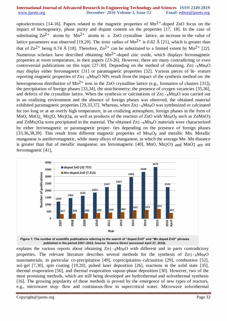
filter against UVA and UVB radiation [11-13] The search for “doped ZnO” and “Mn doped ZnO”
phrases in the “Science Direct” scientific search engine yielded 32,757 and 7,213 matches, respectively,
(April 2016) in various research fields. The number of published scientific papers confirms the growing
interest in Mn2+-doped zinc oxide (Figure 1). It is generally known that selective doping enables
controlling the semi- conductor properties of ZnO, such as forbidden band or conductivity. The diversity
of ZnO modifications by doping with various transition metal ions (e.g., Co, Mn, Ni, Fe, Cr, V)
considerably increases the capabilities of applying that material in electronics, spintronics and
International Journal of Advanced Research in Engineering Technology and Sciences ISSN 2349-2819 www.ijarets.org December- 2016 Volume-3, Issue-12 Email- [email protected]
[email protected] Page 32
optoelectronics [14-16]. Papers related to the magnetic properties of Mn2+-doped ZnO focus on the
impact of homogeneity, phase purity and dopant content on the properties [17, 18]. In the case of
substituting Zn2+ atoms by Mn2+ atoms in a ZnO crystalline lattice, an increase in the value of
lattice parameters was observed [19,20]. The ionic radius of Mn2+ is 0.82 Å [21], which is greater than
that of Zn2+ being 0.74 Å [18]. Therefore, Zn2+ can be substituted to a limited extent by Mn2+ [22].
Numerous scholars have described obtaining Mn2+-doped zinc oxide, which displays ferromagnetic
properties at room temperature, in their papers [23-26]. However, there are many contradicting or even
controversial publications on this topic [27-30]. Depending on the method of obtaining, Zn1−xMnxO
may display either ferromagnetic [31] or paramagnetic properties [32]. Various pieces of lit- erature
reporting magnetic properties of Zn1−xMnxO NPs result from the impact of the synthesis method on: the
heterogeneous distribution of Mn2+ ions in the ZnO crystalline lattice (e.g., formation of clusters [31]),
the precipitation of foreign phases [33,34], the stoichiometry; the presence of oxygen vacancies [35,36],
and defects of the crystalline lattice. When the synthesis or calcinations of Zn1−xMnxO was carried out
in an oxidizing environment and the absence of foreign phases was observed, the obtained material
exhibited paramagnetic properties [29,33,37]. Whereas, when Zn1−xMnxO was synthesized or calcinated
for too long or at an overly high temperature, in an oxidizing atmosphere, foreign phases in the form of
MnO, MnO2, Mn2O, Mn3O4, as well as products of the reaction of ZnO with MnxOy such as ZnMnO3
and ZnMn2O4 were precipitated in the material. The obtained Zn1−xMnxO materials were characterized
by either ferromagnetic or paramagnetic proper- ties depending on the presence of foreign phases
[33,36,38,39]. This result from different magnetic properties of MnxOy and metallic Mn. Metallic
manganese is antiferromagnetic, while many alloys of manganese, in which the average Mn–Mn distance
is greater than that of metallic manganese, are ferromagnetic [40]. MnO, Mn2O3 and MnO2 are ant
ferromagnetic [41],
explains the various reports about obtaining Zn1−xMnxO with different and in parts contradictory
properties. The relevant literature describes several methods for the synthesis of Zn1−xMnxO
nanomaterials, in particular co-precipitation [49], coprecipitation–calcination [29], combustion [52],
sol–gel [7,30], spin coating [19,20], pulsed laser deposition [26], reactions in the solid state [35],
thermal evaporation [56], and thermal evaporation vapour-phase deposition [30]. However, two of the
most promising methods, which are still being developed are hydrothermal and solvothermal synthesis
[16]. The growing popularity of these methods is proved by the emergence of new types of reactors,
e.g., microwave stop- flow and continuous-flow in supercritical water. Microwave solvothermal
Figure 1: The number of scientific publications referring to the search of “doped ZnO” and “Mn doped ZnO” phrases
published in the period 2007–2015. Source: Science Direct (accessed April 27, 2016).

International Journal of Advanced Research in Engineering Technology and Sciences ISSN 2349-2819 www.ijarets.org December- 2016 Volume-3, Issue-12 Email- [email protected]
[email protected] Page 33
synthesis (MSS) is quicker, purer, and more energy and cost efficient than conventional synthesis
methods. The microwave radiation employed is a highly effective method of providing energy to the
reaction chamber, which results in a more uniform and rapid heating in comparison with traditional
methods of heat transfer. The MSS method is a “wet chemistry” method. This means that the precursor
is obtained from solutions of substrates, which are mixed in precisely deter- mined quantities, and the
synthesis is carried out under con- trolled conditions (temperature, pressure, time). The synthesis
product is a precipitate, which is mainly subjected to filtering, rinsing and drying. The advantages of the
microwave solvothermal synthesis are purity (Teflon reaction chamber, contactless heating method),
short process duration, precise control over parameters (time, pressure), product homogeneity
(volumetric heating), control over dopant content, high efficiency, and surface modification. MSS
products are characterized by homogeneous morphology, purity, narrow size distribution and low
agglomeration
The present paper contains an attempt to obtain ZnO nano-paricles with a Mn2+ dopant content
of up to 25 mol %. For the synthesis we selected an organic solvent with weak reducing properties to
prevent the precipitation of foreign phases, which is caused above all by the changed oxidization state of
Mn2+ ions.
But when a reducing environment was selected for sample calcinations, also precipitations of ZnMnO3
and ZnMn2O4 phase emerged in Zn1−xMnxO and the material displayed only ferromagnetic properties
[36]. Ferromagnetic properties of Zn1−xMnxO are explained by the presence of oxygen vacancies,
manganese in various oxidation states (II–IV), and dopant clusters. The formation of clusters of Mn2+
dopant in ZnO NPs, This, in turn, leads to different magnetic properties than those encountered in
nanomaterials with the same dopant content but with a different distribution of ions or dopant clusters in
the crystalline lattice (Figure 2) .
Despite the efforts made by numerous research groups and despite the development of new
synthesis methods, obtaining nanomaterials with reproducible properties proves a very complex and
problematic task. Obtaining Zn1−xMnxO nanomaterials with reproducible optoelectronic and magnetic
properties remains an unsolved issue. Differing properties of the obtained Zn1−xMnxO result from the
complexity of chemical reactions and the limitations of the currently employed methods. The lack of
simultaneous control over chemical composition, stoichiometry, dopant homogeneity, particle size
distribution, shape, phase purity, surface modification and agglomeration, makes it difficult to obtain NPs
[22]. The primary cause of the lack of reproducibility of magnetic properties in the case of Zn1−xMnxO
is the lack of control over the doping impact on the formation of oxygen vacancies, crystalline lattice
defects and dopant clusters. It is presumed that there are several competitive chemical reactions in the
reaction of Zn1−xMnxO synthesis, such as the oxidization of Mn2+ ions, the formation of MnxOy,
the reduction of Mn2+ ions to metallic Mn, and the reaction of Mnx Oy with ZnO leading to the
formation of spinals (ZnMnO3, ZnMn2O4). These reactions may occur simultaneously depending
on the synthesis method, the synthesis parameters and the method of precursor preparation. The
microwave solvothermal synthesis was selected for obtaining Zn1−xMnxO. It was shown before by us
that the MSS method led to fully crystallized Co2+-doped ZnO without foreign phases and with a
uniform particle size and shape.

International Journal of Advanced Research in Engineering Technology and Sciences ISSN 2349-2819 www.ijarets.org December- 2016 Volume-3, Issue-12 Email- [email protected]
[email protected] Page 34
EXPERIMENTAL SUBSTRATES
Zinc acetate dehydrate (Zn(CH3COO)2·2H2O), analytically pure, SKU: 112654906-1KG;
ethylene glycol (1,2-ethanediol, C2H4(OH)2), pure, SKU: 114466303-5L and manganese(II) acetate tetra
hydrate (Mn(CH3COO)2·4H2O), analytically pure, SKU: 116167509-100g were purchased from New
Delhi. The reagents were used without additional purification.
D =N/ SS.ρ
Synthesis of Zn1−xMnxO NPs
Zn1−xMnxO NPs were obtained by the MSS method. The pre- cursor was obtained by dissolving powder
mixtures, composed of 1, 5, 10, 15, 20, 25 mol % of manganese acetate in zinc acetate, in ethylene glycol
(Table 1). The reference sample of ZnO was obtained from the precursor without adding the Mn2+
doping. The mixture of the acetates in glycol (75 mL) was heated to 70 °C and stirred using a magnetic
stirrer (SLR, SI Analytics, Germany) until the components were completely dis- solved. After cooling
down to ambient temperature the solution was poured to the Teflon reaction chamber with a total volume
of 110 mL [66].The synthesis reaction initiated by microwave radiation was carried out in a microwave
reactor (Model 02-02, 600 W,2.45 GHz, ERTEC, Poland) at a temperature of 200 °C. The synthesis of
Mn2+-doped zinc oxide in ethylene glycol can be described through the following equation:
server to extract the crystallite size distribution for XRD peaks. Unlike the standard fitting, the tool does
not act in the reciprocal space at all, but solves sets of equations in a few auxiliary spaces simultaneously.
This allows for an analysis of XRD data with heavily convoluted reciprocal space peaks [68,69].
MEASUREMENT OF DENSITY AND SPECIFIC SURFACE AREA
Density measurements were carried out using a helium pycnometer (AccuPyc II 1340 FoamPyc
V1.06, Micromeritics, USA), in accordance with ISO 12154:2014 at the temperature of 25 ± 2 °C. The
density of a material obtained using helium pycnometry is called, e.g., skeleton density, pycnometric
density, true density and helium density in the relevant literature. The specific surface area of NPs was
determined using the analysis of nitrogen adsorption isotherm by the BET
Figure 2: Indicative examples of the possible distribution of Mn2+ dopant in zinc oxide crystalline lattice. Black circles: Mn2+ dopant, white
circles: ZnO. a) Unclustered distribution of dopant; b) clustered distribution of dopant; c) random distribution of dopant.

International Journal of Advanced Research in Engineering Technology and Sciences ISSN 2349-2819 www.ijarets.org December- 2016 Volume-3, Issue-12 Email- [email protected]
[email protected] Page 35
(Brunauer–Emmett–Teller) method (Gemini 2360, V 2.01, Micromeritics), in accordance with ISO
9277:2010. Prior to performing measurements of both density and specific surface area, the samples
were subject to 2 h desorption in a desorption station (FlowPrep, 060 Micromeritics), at a temperature
of 150 °C with a flow of helium of 99.999% purity. Based on the determined specific surface area and
density, the average size of particles was determined, with the assumption that all particles are spherical
and identical [70]. Equation 2 was used for calculating the average particle size, where D is the average
diameter of the of particles [µm], N is a shape coefficient being (N = 6) for sphere, SSA is the specific
surface area [m2/g] and ρ the density [g/cm3].
Morphologic characteristics The morphology of NPs was determined using scanning electron microscopy (SEM) (ZEISS,
Ultra Plus, Germany). The samples were coated with a thin carbon layer using a sputter coater (SCD
005/CEA 035, BAL-TEC, Switzerland).
Chemical composition analysis
The chemical composition analysis was carried out by using visible-light spectrophotometry
(DR 3900, Hach Lange, Germany). The analysis of the content of Zn2+ ions was carried out by using
the Zincon method No. 8009 (Hach Lange). The analysis of the content of Mn2+ ions was carried out
by using the 1-(2-pyridylazo)-2-naphthol (PAN) method No. 8149 (Hach Lange). The chemical
composition analysis was carried out by using inductively coupled argon plasma optical emission
spectrometry (ICP-OES) (Thermo Scientific, iCAP model 6000, Great Britain).Samples for the
quantitative analysis were prepared as follows: 5 mg of powder was weighed in a 110 mL
Teflon vessel and 15 mL of deionised water (HLP 20UV, Hydrolab, Poland) was added; then 6
mL of HNO3 was added and the solution subjected to one microwave heating cycle in a Magnum II
reactor (600 W, 2.45 GHz, ERTEC, Poland). After cooling the sample volume was filled up to 50 mL
with deionized water. The pH of samples before the colorimetric analysis was adjusted in accordance
with the recommendations of procedures No. 8009 and No. 8149.Quantitative microanalysis was carried
out through energy- dispersive X-ray spectroscopy (EDS) by using an EDS analyzer (Quantax 400,
Bruker, USA). Samples for EDS tests were pressed to pellets with a diameter of 5 mm.
RESULTS AND DISCUSSION
MORPHOLOGY
Figure 3 and Figure 4 present representative SEM images of Zn1−xMnxO NPs. They show
particles with homogeneously distributed spherical shapes. An impact of the content of Mn2+dopant on
the morphology of Zn1−xMnxO powder was ob- served. Powders with dopant contents of 5, 10, 15,
20 and 25 mol % are composed of dense structures forming conglomerates whose shape resembles the
structure of a cauliflower (Figure 4). In the case of dopant contents of 0 or 1 mol %, loose Nanopowder
111111 111
Figure 3: SEM images of NPs of Zn1−xMnxO with dopant concentrations of: a) 0 mol %, b) 1 mol %, c) 5 mol %, d) 10 mol %, e) 15 mol %, f) 20 mol % and g) 25 mol %.
Figure 3: SEM images of NPs of Zn1−xMnxO with dopant concentrations of: a) 0 mol %, b) 1 mol %, c) 5 mol %, d) 10 mol %, e) 15 mol %,
f) 20 mol % and g) 25 mol %.

International Journal of Advanced Research in Engineering Technology and Sciences ISSN 2349-2819 www.ijarets.org December- 2016 Volume-3, Issue-12 Email- [email protected]
[email protected] Page 36
was obtained. It can be noticed that the average particle size decreases with increasing content of Mn2+
dopant in the NPs. The average particle size decreases from circa 30–35 nm to 15–25 nm with an
increase in the content of Mn2+ dopant from 0 to 20 mol %. In the case of the powder with a dopant
content of 25 mol %, the average particle size was circa 20–25nm. SEM tests reveal that each precursor
composition must be treated individually. That means that synthesis parameters must be optimized for
each precursor composition in order to eliminate the process of agglomeration and formation of
conglomerates of Zn1−xMnxO NPs.
PHASE COMPOSITION The XRD tests of the samples did not reveal a presence of foreign phases in the obtained
Zn1−xMnxO NPs, and all diffraction peaks can be attributed to the hexagonal phase ZnO (Figure 5).
Zinc oxide is characterized by hexagonal wurtzite structure (JCPDS No. 36-1451, space group: P63mc)
with two lattice parameters a and c [4]. The parameters of ZnO crystalline lattice assume the values a =
3.2498 Å and c = 5.2066 Å, where its c/a ratio of 1.6021 is close to that of a close-packed hexagonal
structure (hcp) c/a = 1.6330. MnO has rock salt structure (space group: Fm−3m) with the lattice
parameter a = 4.4475 Å. The radius of Mn2+ ions is bigger than that of Zn2+ ions by 0.08 Å, which
explains the considerable changes in the lattice parameters (Table 2). Both lattice parameters a and c
increase with increasing dopant content from 1 to 25 mol % (Figure 6). The results of the c/a lattice
parameter ratio reveals that the change of the dopant content in Zn1−xMnxO leads to a change in the
proportions of the unit cell dimensions (Table 2). The obtained results of crystallite sizes da and dc
(Table 3, Figure 7) indicate that the increase of Mn2+- dopant content in ZnO leads to changes in
proportions (asymmetry) of crystallite sizes.. If the dc/da ratio assumes a value of different from 1, means
particles exhibit a spherical/ elliptical shape.
Figure 5: XRD diffraction patterns of Zn1−xMnxO NPs, with the nominal dopant content in the solution being 0, 1, 5, 10, 15, 20, 25 mol % and its comparison with the standard pattern of wurtzite-phase ZnO (JCPDS No. 36-1451).

International Journal of Advanced Research in Engineering Technology and Sciences ISSN 2349-2819 www.ijarets.org December- 2016 Volume-3, Issue-12 Email- [email protected]
[email protected] Page 37
Table 2: Lattice parameters and ratio of lattice parameters of the obtained Zn1−xMnxO NPs.
sample
lattice parameters
lattice
parameter
lattice parameter
ratio a ± σ [Å] c ± σ [Å] ratio c/a c/a in hcp ZnO
ZnO (JCPDS No. 36-
1451)
3.2498 5.2066 1.6021 1.6330
ZnO 3.2499 ± 0.0001 5.2066 ± 0.0003 1.6021 Zn0.99Mn0.01O 3.2506 ± 0.0002 5.2072 ± 0.0004 1.6019 Zn0.95Mn0.05O 3.2523 ± 0.0003 5.2092 ± 0.0006 1.6017 Zn0.90Mn0.10O 3.2535 ± 0.0004 5.2111 ± 0.0004 1.6017 Zn0.85Mn0.15O 3.2564 ± 0.0005 5.2138 ± 0.0008 1.6011 Zn0.80Mn0.20O 3.2564 ± 0.0004 5.2146 ± 0.0004 1.6013 Zn0.75Mn0.25O 3.2593 ± 0.0005 5.2174 ± 0.0008 1.6008
Despite the presence of as much as 25 mol % dopant in the precursor solution, no foreign phases
in the form of Zn MnO3, Zn Mn2O4, metallic Mn, or MnxOy were observe of foreign phase detectability
in the diffraction method (XRD) can be as high as 5–6 atom %.in the synthesis product, which proves
that the organic solvent selected by us (ethylene glycol) prevented competitive reactions and a change of
the oxidization state of Mn2+ in the course of the synthesis.
Table 3: Crystallite sizes and size ratios of the obtained Zn1−xMnxO NPs.
Sample average crystallite size, calculated through Scherrer’s formula size ratio
dc/da da
[nm]
dc
[nm]
ZnO 22 28 1.273
Zn0.99Mn
0.01O
21 26 1.238
Zn0.95Mn
0.05O
18 19 1.056
Zn0.90Mn
0.10O
17 15 0.882
Zn0.85Mn
0.15O
18 15 0.833
Zn0.80Mn
0.20O
16 12 0.750
Zn0.75Mn
0.25O
19 13 0.684
Figure 6: Lattice parameters versus nominal Mn2+ content of 1−xMnxO samples.

International Journal of Advanced Research in Engineering Technology and Sciences ISSN 2349-2819 www.ijarets.org December- 2016 Volume-3, Issue-12 Email- [email protected]
[email protected] Page 38
CHEMICAL COMPOSITION AND IMPACT OF DOPANT ON THE COLOUR OF NPs
The real content (RC) of manganese dopant in Zn1−xMnxO is presented in Table 4. The RC of
dopant in Zn1−x is smaller by circa 78% than the expected value of dopant arising from the nominal
content (NC) of the dopant in the precursor solution. The difference in sizes of Zn2+ and Mn2+ ionic
radii is the reason for the low doping efficiency of Zn1−xMnxO NPs. The chemical composition
analysis was carried out by three methods: ICP-OES, colorimetry and X-ray microanalysis. The most
often used methods in the relevant literature are ICP-O and X-ray microanalysis. All the employed
methods provided mutually different results (Table 4).This resulted from the limitations and accuracy of
the various analytical techniques in relation to the quantitative determination of zinc and manganese.
ICP-OES analysis is regarded as the most accurate and precise method. Figure 8 describes the
correlation between NC in the precursor and RC of Mn2+ dopant in NPs. The average efficiency of
doping during the synthesis of Zn1−xMnxO in ethylene glycol was merely 22 mol %, being four times
smaller than in the case of doping ZnO with Co2+ ions [66]. The derived formula (y = −0.0057x2 +
0.353x − 0.0447, where y is the real and x is the nominal dopant content) enables the control of RC of
the dopant in Zn1−xMnxO NPs at the stage of precursor preparation. The nominal contents of
manganese dopant in Zn1−xMnxO were used for denominating the samples in this paper.The doping of
zinc oxide with Mn2+ ions leads to a change in the optical properties of the material, which is proved
by the change of the sample colour (Figure 9 and Figure 10). The obtained Zn1−xMnxO NPs,
depending on the Mn2+-dopant content, have differing shades of yellow and orange. The intensity of
NPs color depends on the dopant content, which is illustrated in Figure 9 and Figure 10. Most of the
Zn1−xMnxO nanostructure materials exhibit strong absorption in the UV and visible range and a strong
UV emission [30].
DENSITY, SPECIFIC SURFACE AREA AND CRYSTALLITE SIZE DISTRIBUTION
The theoretical density of ZnO is 5.606 g/cm3. The pycnometric density of the obtained
reference sample of ZnO NPs without doping amounted to 5.09 g/cm3. The difference between the
nano density and the theoretical density of ZnO can result above all from surface defects, the presence of
Zn(OH)2 hydroxides and the nonstoichiometric composition. The density of Zn1−xMnxO, irrespectively
of the content of Mn2+ dopant, was constant at about 5.0 g/cm3. The lower density of Zn1−xMnxO
is related to the smaller atomic weight of Mn (54.93 u) in comparison with the Zn atoms (65.38 u)
in Zn1−xMnxO, and to the possible presence of a greater quantity of defects in the crystalline lattice. The
specific surface area of Zn1−xMnxO ranged from 40 to 70 m2/g (Table 5). The average size of
Figure 7: Dependence of the changes in crystallite size on the nomi- nal content of Mn2+-dopant in Zn1−xMnxO.

International Journal of Advanced Research in Engineering Technology and Sciences ISSN 2349-2819 www.ijarets.org December- 2016 Volume-3, Issue-12 Email- [email protected]
[email protected] Page 39
Zn1−xMnxO particles calculated based on the specific surface area ranged from 17 to 30nm (Table 5).
Based on the XRD analysis using the Nanopowder XRD Processor Demo web application, the average
size and the size distribution of crystallites were determined for Zn1−xMnxO NPs (Figure 11).
Zn1−xMnxO material was characterized by an average crystal- lite size from 19 to 26 nm (Table 5), with
a narrow distribution, which ranged from 30–35 nm to 40–60 nm depending on the dopant content
(Figure 11). When comparing the obtained results from the Nanopowder XRD Processor Demo
application and with that from Scherrer’s formula, similar crystallite sizes were obtained. The results
fall within the range of the standard deviation of methods (Table 5).
The particle sizes calculated based on the specific surface are with an accuracy of 2–6 nm, which
confirms that: the nano-paricles are monocrystalline;
the formed structures of nano-paricles conglomerates (Figure 2 and Figure 3) do not form
aggregates;
the size of crystallites is equal to the size of nanoparticles, thanks to which these expressions can be
used inter- changeably in this paper;
The obtained crystallite size distribution may be interpreted as particle size distribution.
Table 5: Characteristic of the Zn1−xMnxO NPs samples.
Sample
specific surface
area by gas
adsorption, as
± σ [m2/g]
skeleton
density by
gas
pycnometry,
ρs ± σ
[g/cm3]
average
particle size
from SSA
BET, d ± σ
[nm]
average
crystallite size
from
Nanopowder
XRD Processor
Demo, d ± σ
[nm]
average
crystallite size
from
Scherrer’s
formula da [nm] dc [nm]
ZnO 42±
1
5.09±0.04 28±1 26±8 22 28
Zn0.99Mn
0.01O
40±
1
4.98±0.05 30±1 24±8 21 26
Zn0.95Mn
0.05O
50±
1
4.95±0.03 24±1 21±6 18 19
Zn0.90Mn
0.10O
60±
1
5.03±0.04 20±1 19±6 17 15
Zn0.85Mn
0.15O
57±
1
5.01±0.04 21±1 20±7 18 15
Zn0.80Mn
0.20O
70±
1
4.97±0.03 17±1 19±10 16 12
Zn0.75Mn
0.25O
63±
1
4.97±0.04 19±1 21±9 19 13
Figure 10: Visual comparison of changes in colours of dry powder of
Zn1−xMnxO NPs depending on the dopant content.

International Journal of Advanced Research in Engineering Technology and Sciences ISSN 2349-2819 www.ijarets.org December- 2016 Volume-3, Issue-12 Email- [email protected]
[email protected] Page 40
CONCLUSIONS
Zn1−xMnxO (x = 0.01, 0.05, 0.10, 0.15, 0.2, 0.25) nanoparticles have been synthesized by
microwave solvothermal synthesis. Zinc and manganese acetates dissolved in ethylene glycol were used
as precursor. Crystalline Zn1−xMnxO NPs with hexagonal wurtzite structure, pure in terms of phase,
were obtained. Zn1−xMnxO was characterized by an average particle size between 17 and 30 nm, a
specific surface area between 40 and70 m2/g and a density of circa 5.0 g/cm3. The average crystallite
size was observed to decrease in line with an increase in the Mn2+ content. SEM images did not reveal
an impact of the dopant on the spherical shape of nanoparticles. However, an impact of an increase in
the Mn2+ dopant content on the shape of agglomerates and conglomerates of Zn1−xMnxO nano-paricles
was observed. The crystalline lattice parameters a and c in Zn1−xMnxO increase in line with the dopant
growth, which is a consequence of the greater ionic radius of Mn2+ dopant. The results confirm the
usability of the developed method for obtaining crystalline Zn1−xMnxO, pure in terms of phase, with a
narrow particle size distribution with the nominal dopant content reaching 25 mol % and doping
efficiency of circa 22%. Our paper also indicates a high potential of microwave thermal synthesis for
obtaining doped ZnO nano-paricles.
REFERENCES 1. Foresight review of nanotechnology, The next industrial revolution; Lloyd’s Register Foundation Report Series:
No.2014.1, April 2014. http://www.lrfoundation.org.uk/news/2014/nanotechnology-review.aspx
2. Nanotechnologies -- Vocabulary -- Part 2: Nano-objects; ISO/TS 80004-2:2015.
3. Vance, M. E.; Kuiken, T.; Vejerano, E. P.; McGinnis, S. P.; Hochella, M. F., Jr.; Rejeski, D.; Hull, M. S. Beilstein J. Nanotechnol. 2015, 6, 1769–1780. doi:10.3762/bjnano.6.181
4. Morkoç, H.; Özgür, Ü. Zinc Oxide: Fundamentals, Materials and Device Technology; Wiley-VCH: Heidelberg, Germany, 2009. doi:10.1002/9783527623945
5. Özgür, Ü.; Alivov, Ya. I.; Liu, C.; Teke, A.; Reshchikov, M. A.; Doğan, S.; Avrutin, V.; Cho, S.-J.; Morkoç, H. J. Appl. Phys. 2005, 98, 041301. doi:10.1063/1.1992666
6. Ozgur, U.; Hofstetter, D.; Morkoc, H. Proc. IEEE 2010, 98, 1255–1268. doi:10.1109/JPROC.2010.2044550
7. Dilonardo, E.; Penza, M.; Alvisi, M.; Di Franco, C.; Palmisano, F.; Torsi, L.; Cioffi, N. Beilstein J. Nanotechnol. 2016,
7, 22–31. doi:10.3762/bjnano.7.3
8. Chen, J.; He, X.; Wang, W.; Xuan, W.; Zhou, J.; Wang, X.; Dong, S. R.; Garner, S.; Cimo, P.; Luo, J. K. J. Mater.
Chem. C 2014, 2, 9109–9114. doi:10.1039/C4TC01307G
9. Xiong, H.-M. Adv. Mater. 2013, 25, 5329–5335. doi:10.1002/adma.201301732
10. Strange, D. M.; Strange, M.; Sue Scale, N.; Nunn, M. E. Pediatr. Dent. 2001, 23, 331–336.
11. Pinnell, S. R.; Fairhurst, D.; Gillies, R.; Mitchnick, M. A.; Kollias, N. Dermatol. Surg. 2000, 26, 309–314., doi:10.1046/j.1524-4725.2000.99237.x
12. Sun, Q.-C.; Xu, X.; Musfeldt, J. L.; Baker, S. N.; Christianson, A. D. Chem. Mater. 2011, 23, 2956–2960. doi:10.1021/cm200582t
13. Mitchnick, M. A.; Fairhurst, D.; Pinnell, S. R. J. Am. Acad. Dermatol. 1999, 40, 85–90. doi:10.1016/S0190-9622(99)70532-3
14. Ohno, H. Science 1998, 281, 951–956. doi:10.1126/science.281.5379.951
15. Pearton, S. J.; Norton, D. P.; Ivill, M. P.; Hebard, A. F.; Chen, W. M.; Buyanova, I. A.; Zavada, J. M. J. Electron. Mater. 2007, 999, 0999-K03-04. doi:10.1557/PROC-0999-K03-04
16. Glaspell, G.; Dutta, P.; Manivannan, A. J. Cluster Sci. 2005, 16, 523–536. doi:10.1007/s10876-005-0024-y
17. Jing, C.; Jiang, Y.; Bai, W.; Chu, J.; Liu, A. J. Magn. Magn. Mater. 2010, 322, 2395–2400. doi:10.1016/j.jmmm.2010.02.044
18. Hao, Y.-M.; Lou, S.-Y.; Zhou, S.-M.; Yuan, R.-J.; Zhu, G.-Y.; Li, N. Nanoscale Res. Lett. 2012, 7, No. 100. doi:10.1186/1556-276X-7-100
19. Ilyas, U.; Rawat, R. S.; Wang, Y.; Tan, T. L.; Lee, P.; Chen, R.; Sun, H. D.; Li, F.; Zhang, S. Appl. Surf. Sci. 2012, 258, 6373–6378. doi:10.1016/j.apsusc.2012.03.043
20. Ali Fatima, A.; Devadason, S.; Mahalingam, T. J. Mater. Sci.: Mater. Electron. 2014, 25, 3466–3472. doi:10.1007/s10854-014-2040-x
21. Allaby, M., Ed. A Dictionary of Earth Sciences, 3rd ed.; Oxford University Press: Oxford, United Kingdom, 2008. doi:10.1093/acref/9780199211944.001.0001
22. Lojkowski, W.; Gedanken, A.; Grzanka, E.; Opalinska, A.; Strachowski, T.; Pielaszek, R.; Tomaszewska-Grzeda, A.; Yatsunenko, S.; Godlewski, M.; Matysiak, H.; Kurzydłowski, K. J. J. Nanopart. Res. 2009, 11, 1991–2002.
doi:10.1007/s11051-008-9559-9

International Journal of Advanced Research in Engineering Technology and Sciences ISSN 2349-2819 www.ijarets.org December- 2016 Volume-3, Issue-12 Email- [email protected]
[email protected] Page 41
23. Pradhan, A. K.; Kai, Z.; Mohanty, S.; Dadson, J. B.; Hunter, D.; Zhang, J.; Sellmyer, D. J.; Roy, U. N.; Cui, Y.; Burger, A.;
Mathews, S.; Joseph, B.; Sekhar, B. R.; Roul, B. K. Appl. Phys. Lett. 2005, 86, 152511. doi:10.1063/1.1897827
24. Chang, Y. Q.; Wang, D. B.; Luo, X. H.; Xu, X. Y.; Chen, X. H.; Li, L.; Chen, C. P.; Wang, R. M.; Xu, J.; Yu, D. P. Appl.
Phys. Lett. 2003, 83, 4020–4022. doi:10.1063/1.1625788
25. Kundaliya, D. C.; Ogale, S. B.; Lofland, S. E.; Dhar, S.; Metting, C. J.; Shinde, S. R.; Ma, Z.; Varughese, B.; Ramanujachary, K. V.; Salamanca-Riba, L.; Venkatesan, T. Nat. Mater. 2004, 3, 709–714. doi:10.1038/nmat1221
26. Aravind, A.; Jayaraj, M. K.; Kumar, M.; Chandra, R. Mater. Sci. Eng., B 2012, 177, 1017–1022. doi:10.1016/j.mseb.2012.05.005
27. Fukumura, T.; Jin, Z.; Kawasaki, M.; Shono, T.; Hasegawa, T.; Koshihara, S.; Koinuma, H. Appl. Phys. Lett. 2001, 78, 958–960. doi:10.1063/1.1348323
28. Kim, S. S.; Moon, J. H.; Lee, B.-T.; Song, O. S.; Je, J. H. J. Appl. Phys. 2004, 95, 454–459. doi:10.1063/1.1632547
29. Alaria, J.; Bouloudenine, M.; Schmerber, G.; Colis, S.; Dinia, A.; Turek, P.; Bernard, M. J. Appl. Phys. 2006, 99, 08M118. doi:10.1063/1.2172887
30. Ma, X.; Wang, Z. Microelectron. Eng. 2001, 88, 3168–3171. doi:10.1016/j.mee.2011.06.021