international journal of mechanical sciences - · pdf filemodels of the cutting edge geometry...
TRANSCRIPT

International Journal of Mechanical Sciences 65 (2012) 157–167
Contents lists available at SciVerse ScienceDirect
International Journal of Mechanical Sciences
0020-74
http://d
n Corr
E-m
journal homepage: www.elsevier.com/locate/ijmecsci
Models of the cutting edge geometry of medical needleswith applications to needle design
Peidong Han n, Demeng Che, Kumar Pallav, Kornel Ehmann
Department of Mechanical Engineering, Northwestern University, 2145 Sheridan Road, Evanston, IL 60208, United States
a r t i c l e i n f o
Article history:
Received 13 May 2012
Received in revised form
20 August 2012
Accepted 25 September 2012Available online 3 October 2012
Keywords:
Tissue cutting
Medical needle design
Cutting edge geometry
Needle insertion
03/$ - see front matter & 2012 Elsevier Ltd. A
x.doi.org/10.1016/j.ijmecsci.2012.09.014
esponding author. Tel.: þ1 84 7467 0712.
ail address: [email protected]
a b s t r a c t
Tissue cutting by a needle is greatly influenced by the geometry of its cutting edges. Yet, there are very
few results in the technical literature that address the issues surrounding the relation between needle
tip and cutting edge geometry and its cutting/insertion force. In the present paper, general mathema-
tical models of the included and inclination angles of a needle’s cutting edge are formulated since they
exert a profound influence on cutting behavior. Specific models for various tip geometries are
developed to investigate four types of needle tips including one-plane, asymmetric three-plane,
symmetric multi-plane, and symmetric three-curved-surface needles. The results show that the cutting
edge of the one-plane needle has a very undesirable configuration. Asymmetric three-plane needles,
such as the lancet and back bevel tip needles, can significantly improve the configuration of the cutting
edge. Back bevel tip needles, in turn, offer even more desirable cutting edge geometry than lancet tip
needles. In evaluating the cutting edge angles of multi-plane needles, it was shown that the included
angle is limited by its tip geometry. To resolve this problem a needle formed by three curved surfaces
was proposed. It was found that this new design has significant potential for reducing patient trauma as
well as target accuracy during needle insertion. The proposed general approach provides the foundation
for designing medical needles with specific cutting edge properties.
& 2012 Elsevier Ltd. All rights reserved.
1. Introduction
Medical needles are the most commonly used medical devicesand are widely used in minimally invasive percutaneous proce-dures such as injection, regional anesthesia, blood sampling,biopsy and brachytherapy. These procedures require inserting aneedle to a target inside the body for either drug delivery or tissuesample removal. Brachytherapy is a medical procedure to placeradioactive seeds inside or near the tumor using a needle forcancer treatment. The success of this procedure depends on theaccurate placement of the seeds. However, inserting a needledeforms the tissue and displaces the target causing placementerrors [1,2]. Substantial practice is needed to avoid placementerrors by compensating for tissue deformation and targetdisplacement caused by the needle tip force and friction. It has beenshown by Alterovitz [2–4] that without preoperative planningplacement errors may be as large as 26% of the prostate diameterresulting in damage to healthy tissue and failure to kill cancerouscells. A practical approach to reducing the placement error is tominimize the needle insertion force. Thus, a needle that createslower insertion forces and smaller displacements of the target is
ll rights reserved.
.edu (P. Han).
critical to the success of the procedure. Additionally, the studies byEgekvist et al. [5,6] and Arendt-Nielsen et al. [7] have shown that theneedle insertion force is positively correlated with the frequency andintensity of pain and trauma. For example, the insertion force issignificantly higher for 27G needle insertions compared to 30Gneedle insertions. Correspondingly, 53% of insertions with the 27Gneedles caused pain and 39% of insertions with 30G needles causedpain. In [8], the bluntness of the needle tip has been found to berelated to the increased pain in subcutaneous injections. Thus,needles with lower insertion forces are important to reduce the painand trauma experienced by the patients during the procedure.
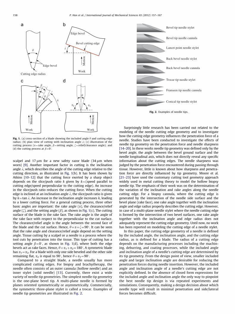
Needle insertion is essentially a tissue cutting process. Theforce of tissue cutting by a needle greatly depends on its cuttingedge geometry. Prior to studying the cutting edge geometry of aneedle, one may begin by examining a blade with a straightcutting edge that is defined by its included angle y and the cuttingedge radius also referred to as the ‘‘roundness’’ of the cutting edge,as illustrated in Fig. 1(a). Maximal knife sharpness is obtained with asmall included angle and a small radius for the cutting edge [9].The knives with a small included angle, such as surgical scalpels andstraight razors, are extremely sharp but fragile. On the contrary,knives that require a tough edge usually have a large included angle.Typical values of the included angle are about 151 for razor bladesand veneer cutting knives, 20–301 for microtome knives and 30–401for kitchen knives [9]. Typical radii of cutting edges are 5 mm for a
�
Work
Mot
ion
Edge bevel
Bevel cutting edge
�
Cutting edge radius
Work
Mot
ion
�
�
Work
Mot
ion
�1�2
Edge bevel
��
�
Fig. 1. (a) cross-section of a blade showing the included angle y and cutting edge
radius; (b) plan view of cutting with inclination angle l; (c) illustration of the
cutting process (a¼rake angle, b¼setting angle, z¼relief/clearance angle); and
(d) the cutting process at b¼01.
Bevel tip needle stylet
Bevel tip needle cannula
Lancet point needle stylet
Back bevel needle stylet
Back bevel needle cannula
Trocar tip needle stylet
Franseen tip needle cannula
Conical tip needle stylet
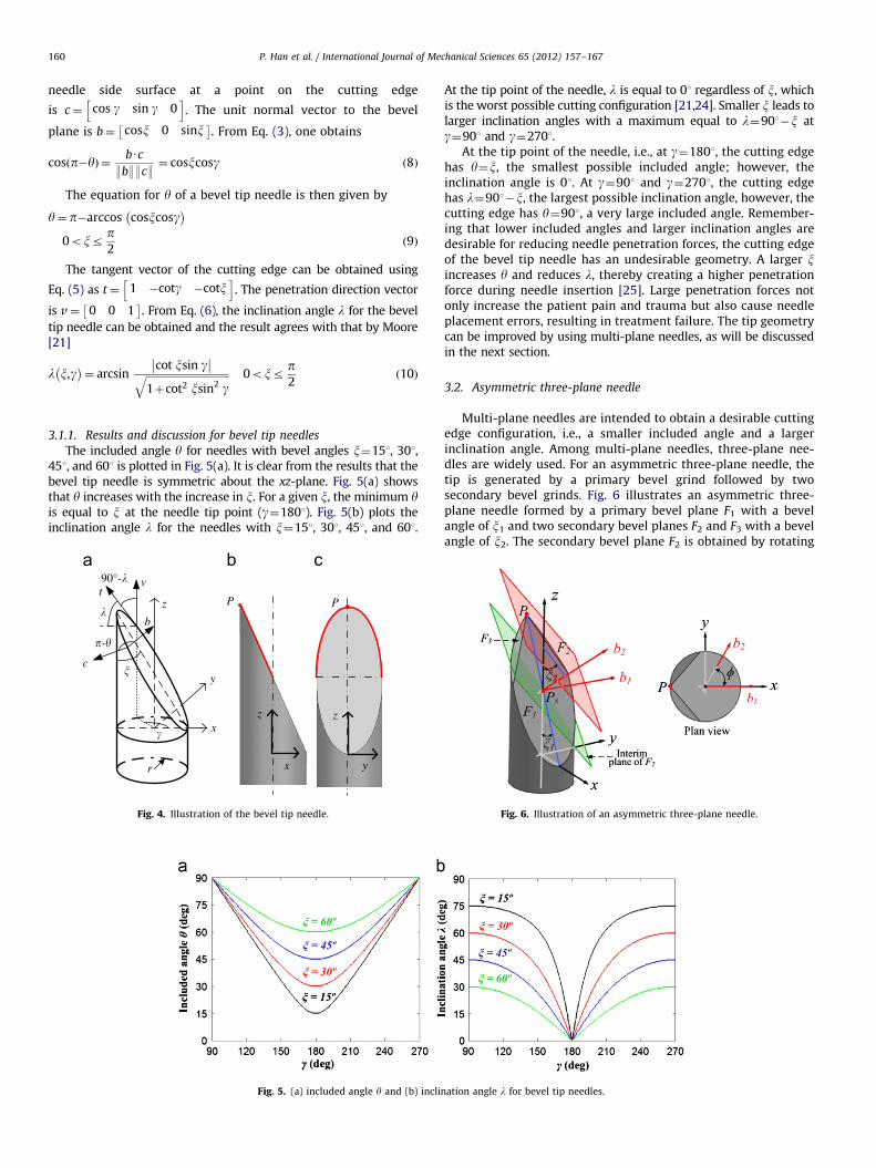
Fig. 2. Examples of needle tips.
P. Han et al. / International Journal of Mechanical Sciences 65 (2012) 157–167158
scalpel and 17 mm for a new safety razor blade (34 mm whenworn) [9]. Another important factor in cutting is the inclinationangle l, which describes the angle of the cutting edge relative to thecutting direction, as illustrated in Fig. 1(b). It has been shown byAtkins [10–12] that the cutting force exerted by a sharp objectdepends on the slice/push ratio k given by k¼(speed parallel tocutting edge/speed perpendicular to the cutting edge). An increasein the slice/push ratio reduces the cutting force. When the cuttingedge is inclined at an inclination angle l, the slice/push ratio is givenby k¼tan l. An increase in the inclination angle increases k, leadingto a lower cutting force. For a general cutting process, three otherbasic angles are important: the rake angle (a), the clearance/reliefangle (z), and the setting angle (b), as shown in Fig. 1(c). The cuttingsurface of the blade is the rake face. The rake angle is the angle ofthe rake face with respect to the perpendicular to the cut surface.The clearance/relief angle is the angle between the second face ofthe blade and the cut surface. Hence, yþaþz¼901. It can be seenthat the rake angle and clearance/relief angle depend on the settingangle. Tissue cutting by a scalpel or a needle is a process where thetool cuts by penetration into the tissue. This type of cutting has asetting angle b¼01, as shown in Fig. 1(d), where both the edgebevels act as rake faces. Hence, yþa1þa2¼1801. A symmetric bladehas a1¼a2. For a blade with only one side beveled and the other sideremaining flat, a2 is equal to 901, hence yþa1¼901.
Compared to a straight blade, a needle usually has morecomplicated cutting edges. For biopsy and brachytherapy, theneedle often consists of an outer cannula (hollow needle) and aninner stylet (solid needle) [13]. Currently, there exist a widevariety of needle tip geometries. The simplest needle tip geometryis the one-plane bevel tip. A multi-plane needle is formed byplanes oriented symmetrically or asymmetrically. Commercially,the symmetric three-plane stylet is called a trocar. Examples ofneedle tip geometries are illustrated in Fig. 2.
Surprisingly little research has been carried out related to themodeling of the needle cutting edge geometry and to investigatehow the cutting edge geometry influences the penetration force of aneedle. Studies have been conducted to investigate the effects ofneedle tip geometry on the penetration force and needle sharpness[14–20]. In these works needle tip geometry was defined only by thebevel angle, the angle between the bevel ground surface and theneedle longitudinal axis, which does not directly reveal any specificinformation about the cutting edges. The needle sharpness wasjudged by the penetration force encountered during passing throughtissue. However, little is known about how sharpness and penetra-tion force are directly influenced by tip geometry. Moore et al.[21–23] have used the customary cutting tool geometry approachwidely used in metal cutting theory to model the hollow biopsyneedle tip. The emphasis of their work was on the determination ofthe variation of the inclination and rake angles along the needlecutting edge. For a biopsy cannula, where the cutting edge isgenerated by the intersection of the needle side surface and thebevel plane (rake face), one rake angle together with the inclinationangle and edge radius properly describes the cutting edge. However,in case of a multi-plane needle stylet where the needle cutting edgeis formed by the intersection of two bevel surfaces, one rake angletogether with the inclination angle and edge radius does notadequately represent the cutting edge geometry. Until now, no workhas been reported on modeling the cutting edge of a needle stylet.
In this paper, the cutting edge geometry of a needle is definedby the included angle, the inclination angle, and the cutting edgeradius, as is defined for a blade. The radius of a cutting edgedepends on the manufacturing processes including the machin-ing, deburring, and coating processes, while the included angleand inclination angle of a needle’s cutting edge are determined byits tip geometry. From the design point of view, smaller includedangle and larger inclination angle are desirable for reducing thepenetration forces during needle insertion. However, the includedangle and inclination angle of a needle’s cutting edge are notexplicitly defined. In the absence of closed form expressions forthe included angle and inclination angle the only way to pinpointthe best needle tip design is via repeated experiments andsimulations. Consequently, making a design decision about whichneedle type will result in minimal penetration and side/lateralforces becomes difficult.

P. Han et al. / International Journal of Mechanical Sciences 65 (2012) 157–167 159
This work addresses the above-mentioned issues in the contextof the needle tip geometry by obtaining general expressions for theincluded angle and inclination angle of the needle cutting edge inSection 2. In Section 3 specific expressions are derived and used toexamine asymmetric needles. At the same time, since asymmetricneedles suffer from excessive deflection and poor targeting accuracythe included angle and inclination angle are also derived andexamined for symmetric needles. It is shown that while symmetricneedles do not suffer from significant deflection issues the minimalinsertion forces are limited due to a limitation on the included angle.A novel needle tip design, a three-cylindrical-surface tip, is proposedthat overcomes this limitation on the included angle of conventionalsymmetric three-plane tip needle while maintaining the advantageof lower deflection provided by symmetry. Therefore, this newdesign has significant potential for reducing patient trauma aswell as target accuracy during needle insertion. Finally, Section 4summarizes this work. The findings of this research will assistmedical needle manufacturers in developing novel needles withlower penetration force to minimize pain and trauma. New biopsyneedles will increase the quality of tissue samples and improvethe accuracy of diagnosis. Needles with lower included and largerinclination angles will reduce the penetration force and place-ment errors in brachytherapy.
2. General mathematical model for included and inclinationangles
In general, a needle tip is generated by planes or curved surfacesintersecting each other. Fig. 3 illustrates a needle tip formed by theintersection of two arbitrary surfaces F1 and F2 and of the needlebody. A Cartesian coordinate system with the z-axis coinciding withthe needle longitudinal axis and x-axis passing through the lowestpoint of the needle tip profile is defined. The cutting edge is theintersection between these two surfaces, and it can be mathemati-cally given by
F1 x,y,zð Þ ¼ 0
F2 x,y,zð Þ ¼ 0
(ð1Þ
The normal vector at a point (x0,y0,z0) on a surface F(x,y,z)¼0is, in turn, given by
N¼ Fx x0,y0,z0
� �Fy x0,y0,z0
� �Fz x0,y0,z0
� �h ið2Þ
where Fx¼qF/qx, Fy¼qF/qy, and Fz¼qF/qz are partial derivatives.At a point M0(x0,y0,z0) on the cutting edge, the normal vector
to surface F1 is N1 ¼ F1,x
� �M0
F1,y
� �M0
F1,z
� �M0
h iand the normal
F1
M0
F2
N1
N2�-�
x
yz
v
t
Fig. 3. Illustration of a needle tip formed by two arbitrary surfaces F1 and F2.
The cutting edge is the intersection of these two surfaces.
vector to surface F2 is N2 ¼ F2,x
� �M0
F2,y
� �M0
F2,z
� �M0
h i, as
illustrated in Fig. 3. The included angle y is the angle betweentwo surfaces F1 and F2. The dot product can be used to determinethis angle. Given two normal vectors N1 and N2, the angle
between the vectors N1 and N2 at M0(x0,y0,z0) is p�y and canbe computed from
cos p�yð Þ ¼N1 � N2
:N1::N2:
¼F1,x
� �M0
F2,x
� �M0þ F1,y
� �M0
F2,y
� �M0þ F1,z
� �M0
F2,z
� �M0ffiffiffiffiffiffiffiffiffiffiffiffiffiffiffiffiffiffiffiffiffiffiffiffiffiffiffiffiffiffiffiffiffiffiffiffiffiffiffiffiffiffiffiffiffiffiffiffiffiffiffiffiffiffiffiffiffiffiffiffi
F1,x
� �2
M0þ F1,y
� �2
M0þ F1,z
� �2
M0
q ffiffiffiffiffiffiffiffiffiffiffiffiffiffiffiffiffiffiffiffiffiffiffiffiffiffiffiffiffiffiffiffiffiffiffiffiffiffiffiffiffiffiffiffiffiffiffiffiffiffiffiffiffiffiffiffiffiffiffiffiF2,x
� �2
M0þ F2,y
� �2
M0þ F2,z
� �2
M0
qð3Þ
and is explicitly given by
y¼ p�arccos
F1,x
� �M0
F2,x
� �M0þ F1,y
� �M0
F2,y
� �M0þ F1,z
� �M0
F2,z
� �M0ffiffiffiffiffiffiffiffiffiffiffiffiffiffiffiffiffiffiffiffiffiffiffiffiffiffiffiffiffiffiffiffiffiffiffiffiffiffiffiffiffiffiffiffiffiffiffiffiffiffiffiffiffiffiffiffiffiffiffiffi
F1,x
� �2
M0þ F1,y
� �2
M0þ F1,z
� �2
M0
q ffiffiffiffiffiffiffiffiffiffiffiffiffiffiffiffiffiffiffiffiffiffiffiffiffiffiffiffiffiffiffiffiffiffiffiffiffiffiffiffiffiffiffiffiffiffiffiffiffiffiffiffiffiffiffiffiffiffiffiffiF2,x
� �2
M0þ F2,y
� �2
M0þ F2,z
� �2
M0
q0B@
1CAð4Þ
For percutaneous procedures, the penetration direction vectorcoincides with the needle longitudinal axis and can be expressedas v¼ 0 0 1
� �, while the tangent vector to the cutting edge can
be given by the cross product of vectors N1 and N2 as
t¼N1 � N2 ¼
i j k
F1,x
� �M0
F1,y
� �M0
F1,z
� �M0
F2,x
� �M0
F2,y
� �M0
F2,z
� �M0
��������
��������ð5Þ
The inclination angle l is the angle between the vector t andthe xy-plane (plane with normal vector v). It can be given by
l¼ arcsin9tUv9:t::v:
ð6Þ
Eqs. (4) and (6) describe the included angle and inclinationangle along the cutting edge formed by the intersection of twogeneral surfaces.
3. Specific mathematical model for included and inclinationangles
In this section, expressions will be given for specific needle tipgeometries. Needle tips generated by planar surfaces will beevaluated first. The mathematical models will provide valuableinformation regarding the included angle and inclination angle ofthe needle cutting edge. The results will help in identifying thedrawbacks of the planar needle and guide the design of new needles.Needle tips generated by curved surfaces will then be investigated.The benefits obtained from curved surfaces will also be described.
3.1. One-plane bevel tip needle
The bevel tip needle is made by one-plane being ground at aspecific bevel angle x, where the leading edge of the needle tipacts as the cutting edge, as marked in Fig. 4. The angular positionof a point on the cutting edge is defined by g in the coordinatesystem, as shown in Fig. 4(a). The parametric equation of thecutting edge for a bevel tip needle with a radius of r is given by
x¼ rcosgy¼ rsingz¼ r 1�cosg
� �cotx ð7Þ
The angle between the needle side surface and the bevel planeis the included angle y. From Eq. (2), the unit normal vector to the
P. Han et al. / International Journal of Mechanical Sciences 65 (2012) 157–167160
needle side surface at a point on the cutting edge
is c¼ cos g sin g 0h i
. The unit normal vector to the bevel
plane is b¼ cosx 0 sinx� �
. From Eq. (3), one obtains
cos p�yð Þ ¼bUc
:b::c:¼ cosxcosg ð8Þ
The equation for y of a bevel tip needle is then given by
y¼ p�arccos cosxcosg� �
0oxrp2
ð9Þ
The tangent vector of the cutting edge can be obtained using
Eq. (5) as t¼ 1 �cotg �cotxh i
. The penetration direction vector
is v¼ 0 0 1� �
. From Eq. (6), the inclination angle l for the bevel
tip needle can be obtained and the result agrees with that by Moore[21]
l x,g� �
¼ arcsincot xsin g�� ��ffiffiffiffiffiffiffiffiffiffiffiffiffiffiffiffiffiffiffiffiffiffiffiffiffiffiffiffiffiffiffiffiffi
1þcot2 xsin2 gq 0oxr
p2
ð10Þ
3.1.1. Results and discussion for bevel tip needles
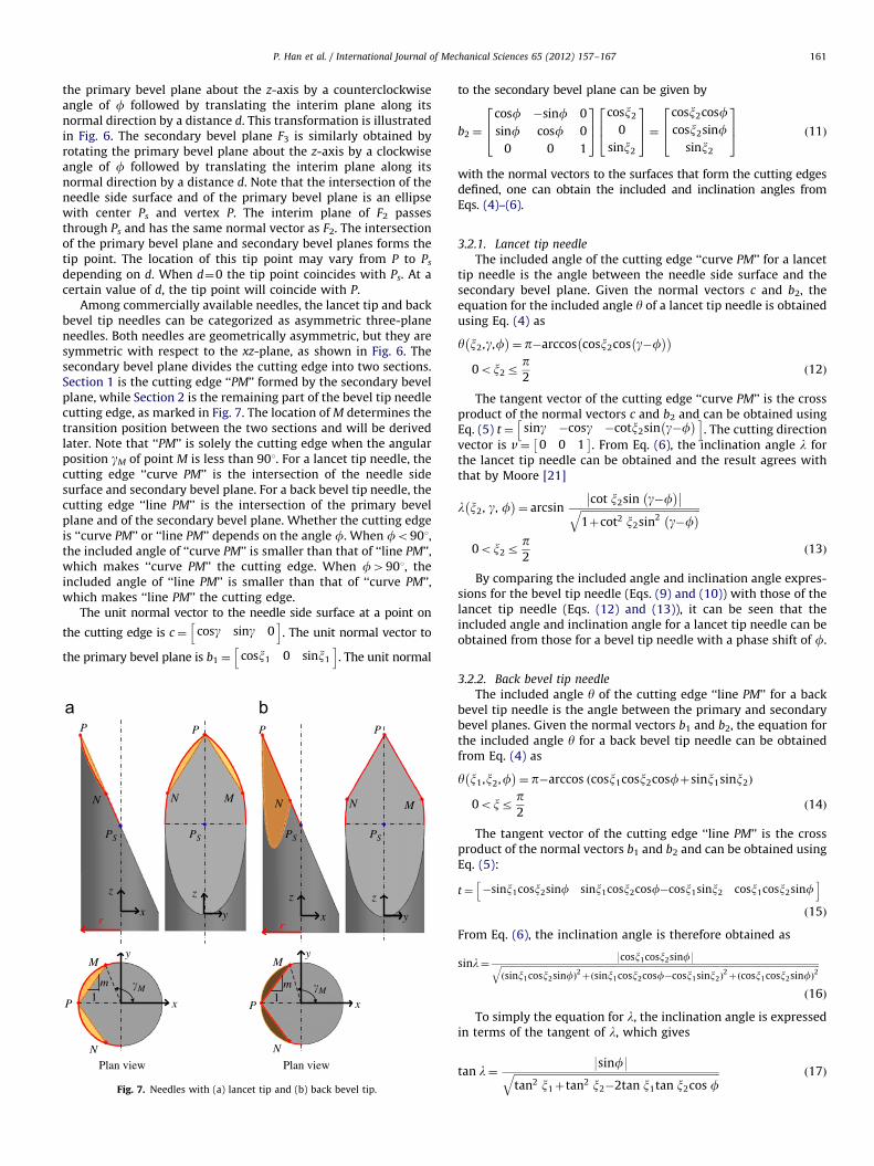
The included angle y for needles with bevel angles x¼151, 301,451, and 601 is plotted in Fig. 5(a). It is clear from the results that thebevel tip needle is symmetric about the xz-plane. Fig. 5(a) showsthat y increases with the increase in x. For a given x, the minimum yis equal to x at the needle tip point (g¼1801). Fig. 5(b) plots theinclination angle l for the needles with x¼151, 301, 451, and 601.
Fig. 5. (a) included angle y and (b) incli
z
y
x
r
90°-�
�
�P
y
z
x
z
P
�-�
tv
c
b
Fig. 4. Illustration of the bevel tip needle.
At the tip point of the needle, l is equal to 01 regardless of x, whichis the worst possible cutting configuration [21,24]. Smaller x leads tolarger inclination angles with a maximum equal to l¼901�x atg¼901 and g¼2701.
At the tip point of the needle, i.e., at g¼1801, the cutting edgehas y¼x, the smallest possible included angle; however, theinclination angle is 01. At g¼901 and g¼2701, the cutting edgehas l¼901�x, the largest possible inclination angle, however, thecutting edge has y¼901, a very large included angle. Remember-ing that lower included angles and larger inclination angles aredesirable for reducing needle penetration forces, the cutting edgeof the bevel tip needle has an undesirable geometry. A larger xincreases y and reduces l, thereby creating a higher penetrationforce during needle insertion [25]. Large penetration forces notonly increase the patient pain and trauma but also cause needleplacement errors, resulting in treatment failure. The tip geometrycan be improved by using multi-plane needles, as will be discussedin the next section.
3.2. Asymmetric three-plane needle
Multi-plane needles are intended to obtain a desirable cuttingedge configuration, i.e., a smaller included angle and a largerinclination angle. Among multi-plane needles, three-plane nee-dles are widely used. For an asymmetric three-plane needle, thetip is generated by a primary bevel grind followed by twosecondary bevel grinds. Fig. 6 illustrates an asymmetric three-plane needle formed by a primary bevel plane F1 with a bevelangle of x1 and two secondary bevel planes F2 and F3 with a bevelangle of x2. The secondary bevel plane F2 is obtained by rotating
nation angle l for bevel tip needles.
Fig. 6. Illustration of an asymmetric three-plane needle.
P. Han et al. / International Journal of Mechanical Sciences 65 (2012) 157–167 161
the primary bevel plane about the z-axis by a counterclockwiseangle of f followed by translating the interim plane along itsnormal direction by a distance d. This transformation is illustratedin Fig. 6. The secondary bevel plane F3 is similarly obtained byrotating the primary bevel plane about the z-axis by a clockwiseangle of f followed by translating the interim plane along itsnormal direction by a distance d. Note that the intersection of theneedle side surface and of the primary bevel plane is an ellipsewith center Ps and vertex P. The interim plane of F2 passesthrough Ps and has the same normal vector as F2. The intersectionof the primary bevel plane and secondary bevel planes forms thetip point. The location of this tip point may vary from P to Ps
depending on d. When d¼0 the tip point coincides with Ps. At acertain value of d, the tip point will coincide with P.
Among commercially available needles, the lancet tip and backbevel tip needles can be categorized as asymmetric three-planeneedles. Both needles are geometrically asymmetric, but they aresymmetric with respect to the xz-plane, as shown in Fig. 6. Thesecondary bevel plane divides the cutting edge into two sections.Section 1 is the cutting edge ‘‘PM’’ formed by the secondary bevelplane, while Section 2 is the remaining part of the bevel tip needlecutting edge, as marked in Fig. 7. The location of M determines thetransition position between the two sections and will be derivedlater. Note that ‘‘PM’’ is solely the cutting edge when the angularposition gM of point M is less than 901. For a lancet tip needle, thecutting edge ‘‘curve PM’’ is the intersection of the needle sidesurface and secondary bevel plane. For a back bevel tip needle, thecutting edge ‘‘line PM’’ is the intersection of the primary bevelplane and of the secondary bevel plane. Whether the cutting edgeis ‘‘curve PM’’ or ‘‘line PM’’ depends on the angle f. When fo901,the included angle of ‘‘curve PM’’ is smaller than that of ‘‘line PM’’,which makes ‘‘curve PM’’ the cutting edge. When f4901, theincluded angle of ‘‘line PM’’ is smaller than that of ‘‘curve PM’’,which makes ‘‘line PM’’ the cutting edge.
The unit normal vector to the needle side surface at a point on
the cutting edge is c¼ cosg sing 0h i
. The unit normal vector to
the primary bevel plane is b1 ¼ cosx1 0 sinx1
h i. The unit normal
x
z
r rx
z
P
NN
Plan view Plan view
P
x
y
x
y
P P
N N
M M
y
z
P
N M
PSPS PS
P
N M
PS
y
z
m1
�M m1
�M
Fig. 7. Needles with (a) lancet tip and (b) back bevel tip.
to the secondary bevel plane can be given by
b2 ¼
cosf �sinf 0
sinf cosf 0
0 0 1
264
375
cosx2
0
sinx2
264
375¼
cosx2cosfcosx2sinf
sinx2
264
375 ð11Þ
with the normal vectors to the surfaces that form the cutting edgesdefined, one can obtain the included and inclination angles fromEqs. (4)–(6).
3.2.1. Lancet tip needle
The included angle of the cutting edge ‘‘curve PM’’ for a lancettip needle is the angle between the needle side surface and thesecondary bevel plane. Given the normal vectors c and b2, theequation for the included angle y of a lancet tip needle is obtainedusing Eq. (4) as
y x2,g,f� �
¼ p�arccos cosx2cos g�f� �� �
0ox2rp2
ð12Þ
The tangent vector of the cutting edge ‘‘curve PM’’ is the crossproduct of the normal vectors c and b2 and can be obtained usingEq. (5) t¼ sing �cosg �cotx2sin g�f
� �h i. The cutting direction
vector is v¼ 0 0 1� �
. From Eq. (6), the inclination angle l forthe lancet tip needle can be obtained and the result agrees withthat by Moore [21]
l x2, g, f� �
¼ arcsincot x2sin g�f
� ��� ��ffiffiffiffiffiffiffiffiffiffiffiffiffiffiffiffiffiffiffiffiffiffiffiffiffiffiffiffiffiffiffiffiffiffiffiffiffiffiffiffiffiffiffiffiffiffiffi1þcot2 x2sin2 g�f
� �q0ox2r
p2
ð13Þ
By comparing the included angle and inclination angle expres-sions for the bevel tip needle (Eqs. (9) and (10)) with those of thelancet tip needle (Eqs. (12) and (13)), it can be seen that theincluded angle and inclination angle for a lancet tip needle can beobtained from those for a bevel tip needle with a phase shift of f.
3.2.2. Back bevel tip needle
The included angle y of the cutting edge ‘‘line PM’’ for a backbevel tip needle is the angle between the primary and secondarybevel planes. Given the normal vectors b1 and b2, the equation forthe included angle y for a back bevel tip needle can be obtainedfrom Eq. (4) as
y x1,x2,f� �
¼ p�arccos cosx1cosx2cosfþsinx1sinx2ð Þ
0oxrp2
ð14Þ
The tangent vector of the cutting edge ‘‘line PM’’ is the crossproduct of the normal vectors b1 and b2 and can be obtained usingEq. (5):
t¼ �sinx1cosx2sinf sinx1cosx2cosf�cosx1sinx2 cosx1cosx2sinfh i
ð15Þ
From Eq. (6), the inclination angle is therefore obtained as
sinl¼ 9cosx1cosx2sinf9ffiffiffiffiffiffiffiffiffiffiffiffiffiffiffiffiffiffiffiffiffiffiffiffiffiffiffiffiffiffiffiffiffiffiffiffiffiffiffiffiffiffiffiffiffiffiffiffiffiffiffiffiffiffiffiffiffiffiffiffiffiffiffiffiffiffiffiffiffiffiffiffiffiffiffiffiffiffiffiffiffiffiffiffiffiffiffiffiffiffiffiffiffiffiffiffiffiffiffiffiffiffiffiffiffiffiffiffiffiffiffiffiffiffiffiffiffiffiffiffiffiffiffiffiffiffiffiffiffiffiffiffiffiffiffiffiffiffiffiffiffiffiffiffiffiffiffiffiffiffiffiffiffiffiffisinx1cosx2sinfð Þ
2þ sinx1cosx2cosf�cosx1sinx2ð Þ
2þ cosx1cosx2sinfð Þ
2q
ð16Þ
To simply the equation for l, the inclination angle is expressedin terms of the tangent of l, which gives
tan l¼9sinf9ffiffiffiffiffiffiffiffiffiffiffiffiffiffiffiffiffiffiffiffiffiffiffiffiffiffiffiffiffiffiffiffiffiffiffiffiffiffiffiffiffiffiffiffiffiffiffiffiffiffiffiffiffiffiffiffiffiffiffiffiffiffiffiffiffiffiffiffiffiffiffiffiffiffiffiffiffiffiffiffiffi
tan2 x1þtan2 x2�2tan x1tan x2cos fq ð17Þ
P. Han et al. / International Journal of Mechanical Sciences 65 (2012) 157–167162
Finally, the inclination angle l for a back bevel needle is givenby
l x1,x2,fð Þ ¼ arctansin f�� ��ffiffiffiffiffiffiffiffiffiffiffiffiffiffiffiffiffiffiffiffiffiffiffiffiffiffiffiffiffiffiffiffiffiffiffiffiffiffiffiffiffiffiffiffiffiffiffiffiffiffiffiffiffiffiffiffiffiffiffiffiffiffiffiffiffiffiffiffiffiffiffiffiffiffiffiffiffiffiffiffiffi
tan2 x1þtan2 x2�2tan x1tan x2cos fq
0B@
1CA
0ox1,2rp2
ð18Þ
3.2.3. Determination of the transition point M
The location of point M determines the transition positionbetween two sections of the cutting edge. More importantly, pointM determines the length of the cutting edge formed by the secondarybevel plane, which influences the shape of the incision hole and thepenetration force [26]. The transition point for a lancet tip cannulahas been derived by Wang et al. [27]. The same approach is used herefor the derivation of the location of point M.
The tangent direction of ‘‘line PM’’ has been given by Eq. (15).The slope of ‘‘line PM’’ in the xy-plane can be expressed as
m¼sinx1cosx2cosf�cosx1sinx2
�sinx1cosx2sinf¼
cotx1tanx2�cosfsinf
ð19Þ
with the point P (�r, 0) and the slope m, the coordinates of pointM in the xy-plane can be solved and are given by M((r�m2r)/(1þm2), 2mr/(1þm2)). The angular position gM of point M can be
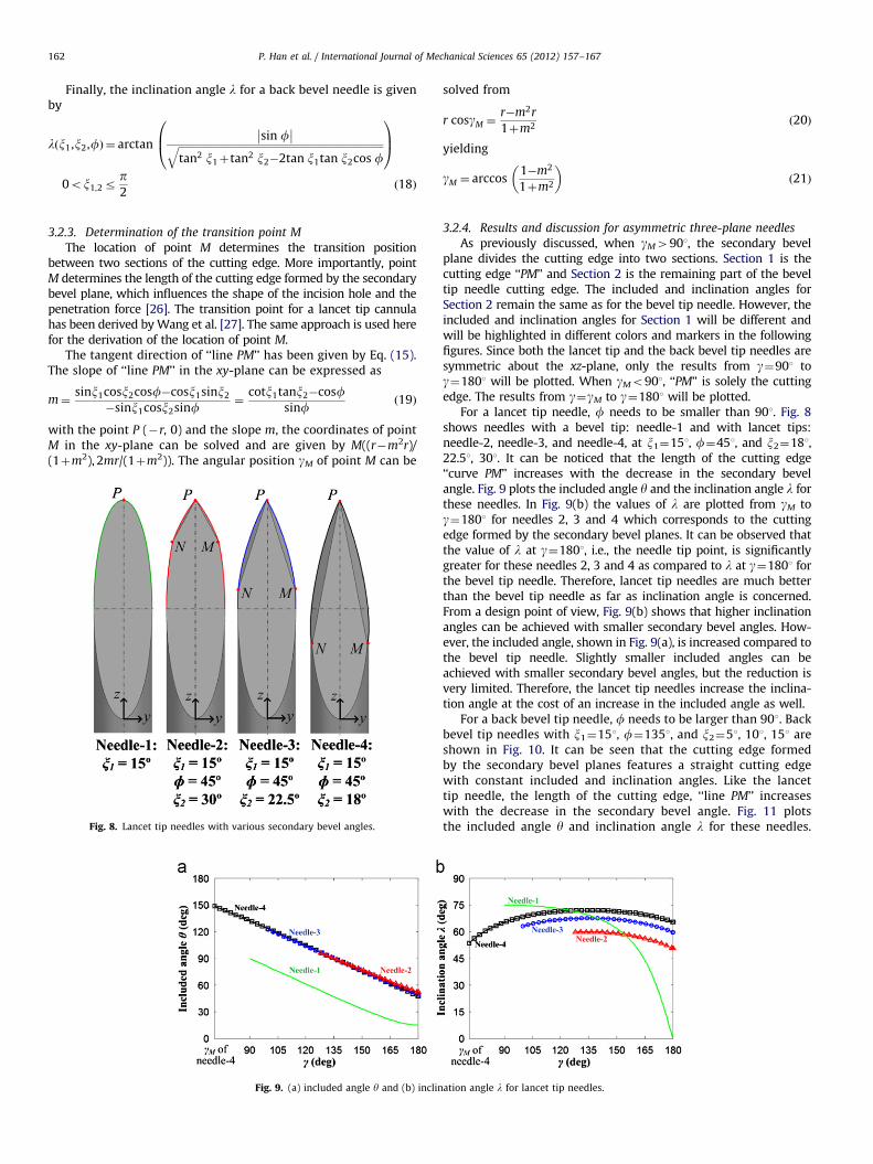
Fig. 8. Lancet tip needles with various secondary bevel angles.
Fig. 9. (a) included angle y and (b) inclin
solved from
r cosgM ¼r�m2r
1þm2ð20Þ
yielding
gM ¼ arccos1�m2
1þm2
� ð21Þ
3.2.4. Results and discussion for asymmetric three-plane needles
As previously discussed, when gM4901, the secondary bevelplane divides the cutting edge into two sections. Section 1 is thecutting edge ‘‘PM’’ and Section 2 is the remaining part of the beveltip needle cutting edge. The included and inclination angles forSection 2 remain the same as for the bevel tip needle. However, theincluded and inclination angles for Section 1 will be different andwill be highlighted in different colors and markers in the followingfigures. Since both the lancet tip and the back bevel tip needles aresymmetric about the xz-plane, only the results from g¼901 tog¼1801 will be plotted. When gMo901, ‘‘PM’’ is solely the cuttingedge. The results from g¼gM to g¼1801 will be plotted.
For a lancet tip needle, f needs to be smaller than 901. Fig. 8shows needles with a bevel tip: needle-1 and with lancet tips:needle-2, needle-3, and needle-4, at x1¼151, f¼451, and x2¼181,22.51, 301. It can be noticed that the length of the cutting edge‘‘curve PM’’ increases with the decrease in the secondary bevelangle. Fig. 9 plots the included angle y and the inclination angle l forthese needles. In Fig. 9(b) the values of l are plotted from gM tog¼1801 for needles 2, 3 and 4 which corresponds to the cuttingedge formed by the secondary bevel planes. It can be observed thatthe value of l at g¼1801, i.e., the needle tip point, is significantlygreater for these needles 2, 3 and 4 as compared to l at g¼1801 forthe bevel tip needle. Therefore, lancet tip needles are much betterthan the bevel tip needle as far as inclination angle is concerned.From a design point of view, Fig. 9(b) shows that higher inclinationangles can be achieved with smaller secondary bevel angles. How-ever, the included angle, shown in Fig. 9(a), is increased compared tothe bevel tip needle. Slightly smaller included angles can beachieved with smaller secondary bevel angles, but the reduction isvery limited. Therefore, the lancet tip needles increase the inclina-tion angle at the cost of an increase in the included angle as well.
For a back bevel tip needle, f needs to be larger than 901. Backbevel tip needles with x1¼151, f¼1351, and x2¼51, 101, 151 areshown in Fig. 10. It can be seen that the cutting edge formedby the secondary bevel planes features a straight cutting edgewith constant included and inclination angles. Like the lancettip needle, the length of the cutting edge, ‘‘line PM’’ increaseswith the decrease in the secondary bevel angle. Fig. 11 plotsthe included angle y and inclination angle l for these needles.
ation angle l for lancet tip needles.

P. Han et al. / International Journal of Mechanical Sciences 65 (2012) 157–167 163
From Fig. 11(b), it can be noticed that the inclination angle hasgreatly increased with the back bevel cut. Higher inclinationangles can be achieved with smaller secondary bevel angles. Atthe same time, Fig. 11(a) shows that the included angle of backbevel tip needle is significantly lower compared to that of thelancet tip needle.
By comparing Fig. 9 with Fig. 11, it can be seen that both thelancet tip needle and back bevel tip needle have large inclinationangles, however, in terms of the included angle, the back bevel tipneedle has a better configuration. Therefore, it is to be expected thatthe insertion forces for the back bevel tip needle will be lower thanthose for the lancet tip needle. This is in fact what was observed bySuzuki et al. [26] who showed that the penetration force by a backbevel tip needle is 40% lower than that by the lancet tip needle. Forboth lancet and back bevel tip needles, it is clear that the includedangle, inclination angle, and cutting edge length depend on x1, f,and x2. The tip geometry may be optimized by varying the angles,which is not the scope of this paper. However the findings from theabove-presented models create an opportunity for medical needlemanufacturers to design lancet and back bevel needles with lowerincluded angles and larger inclination angles.
An issue with asymmetric needles, including the bevel tip needle,lancet needle, and back bevel tip, is needle deflection duringpercutaneous procedures, because the tissue exerts higher forceson one side. Needle bending is one of the reasons for placement
Fig. 10. Back bevel tip needles with various secondary bevel angles.
Fig. 11. (a) included angle y and (b) inclina
errors in needle insertion procedures. Preoperative planning isneeded to avoid placement errors. A symmetric needle reduces thedeflection during needle insertion. Therefore, mathematical modelsfor symmetric needles will be given in the following sections.
3.3. Symmetric multi-plane needle
A symmetric multi-plane needle is formed by bevel planesoriented symmetrically. The cutting edge is the intersectionbetween two bevel planes. This needle features straight cuttingedges with a constant included angle and inclination angle giventhe number of bevel planes P and bevel angle x. A symmetric two-plane stylet has P¼2 and therefore has a single cutting edge. Thenumber of cutting edges for a multi-plane stylet is equal to P forP42. Fig. 12 illustrates the cutting edges, bevel planes, and bevelangles for a symmetric three-plane needle, which is the mostpopular commercially available needle today.
The unit normal vector to the bevel plane formed by the cutting
edges PB and PC, as shown in Fig. 12, is b1 ¼ cosx 0 sinx� �
. The
unit normal vector to the bevel plane formed by the cutting edges ofPC and PA can be given by
b2 ¼
cosf �sinf 0
sinf cosf 0
0 0 1
264
375
cosx0
sinx
264
375¼
cosxcosfcosxsinf
sinx
264
375 ð22Þ
where f is the rotation angle about the z-axis between successive
bevel planes and is therefore f¼2p/P, and P is an integer represent-ing the number of planes.
tion angle l for back bevel tip needles.
x
y
z
r
P
OA
B
C
M
P
A
B
C
Fig. 12. Illustration of a three-plane symmetric needle.
x
y
y
z
y1
z1
R
rCylinder F3 in CS3
Cylinder F1 in CS1
Cylinder F2 in CS2
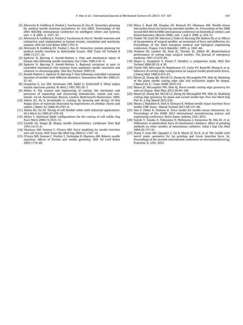
Fig. 14. Illustration of a needle formed by three cylinders, (a) front view showing
the needle and one cylinder, and (b) plan view showing the needle and three
cylinders.
P. Han et al. / International Journal of Mechanical Sciences 65 (2012) 157–167164
As before, with the normal vectors to the surfaces that formthe cutting edges determined, the included and inclination anglescan be obtained from Eqs. (4)–(6).
The included angle y for a symmetric multi-plane needle is theangle between two successive bevel planes. With the normalvectors b1 and b2, the equation for y for a multi-plane needle canbe obtained from Eq. (4) as
y¼ p�arccos cos2 xcos fþsin2 x �
f¼ 2p=P
0oxrp2
ð23Þ
The tangent vector of the cutting edge is the cross product ofthe normal vectors b1 and b2 and can be given by t¼
�sinf cosf�1 sinfcotxh i
. The angle between the xy-plane
and vector t is the inclination angle l. From Eq. (6), the inclinationangle can be given by
sin l¼cot xsin fffiffiffiffiffiffiffiffiffiffiffiffiffiffiffiffiffiffiffiffiffiffiffiffiffiffiffiffiffiffiffiffiffiffiffiffiffiffiffiffiffiffiffiffiffiffiffiffiffiffiffiffiffi
2�2cos fþsin2 fcot2 xq ð24Þ
To simply the equation, the inclination angle can be expressedas
tanl¼ cosf2
cotx ð25Þ
Hence, equation for l of a symmetric multi-plane needle canfinally be given by
l x,fð Þ ¼ arctan cosf2
cotx�
f¼ 2p=P
0oxrp2
ð26Þ
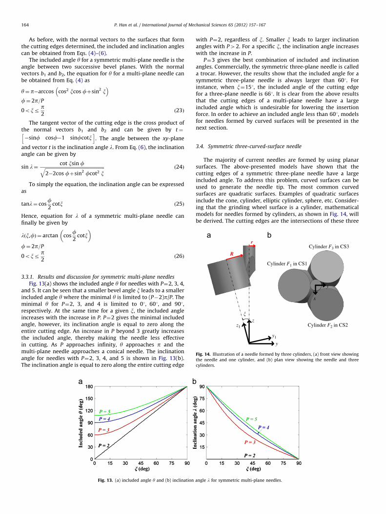
3.3.1. Results and discussion for symmetric multi-plane needles
Fig. 13(a) shows the included angle y for needles with P¼2, 3, 4,and 5. It can be seen that a smaller bevel angle x leads to a smallerincluded angle y where the minimal y is limited to (P�2)p/P. Theminimal y for P¼2, 3, and 4 is limited to 01, 601, and 901,respectively. At the same time for a given x, the included angleincreases with the increase in P. P¼2 gives the minimal includedangle, however, its inclination angle is equal to zero along theentire cutting edge. An increase in P beyond 3 greatly increasesthe included angle, thereby making the needle less effectivein cutting. As P approaches infinity, y approaches p and themulti-plane needle approaches a conical needle. The inclinationangle for needles with P¼2, 3, 4, and 5 is shown in Fig. 13(b).The inclination angle is equal to zero along the entire cutting edge
Fig. 13. (a) included angle y and (b) inclination
with P¼2, regardless of x. Smaller x leads to larger inclinationangles with P42. For a specific x, the inclination angle increaseswith the increase in P.
P¼3 gives the best combination of included and inclinationangles. Commercially, the symmetric three-plane needle is calleda trocar. However, the results show that the included angle for asymmetric three-plane needle is always larger than 601. Forinstance, when x¼151, the included angle of the cutting edgefor a three-plane needle is 661. It is clear from the above resultsthat the cutting edges of a multi-plane needle have a largeincluded angle which is undesirable for lowering the insertionforce. In order to achieve an included angle less than 601, modelsfor needles formed by curved surfaces will be presented in thenext section.
3.4. Symmetric three-curved-surface needle
The majority of current needles are formed by using planarsurfaces. The above-presented models have shown that thecutting edges of a symmetric three-plane needle have a largeincluded angle. To address this problem, curved surfaces can beused to generate the needle tip. The most common curvedsurfaces are quadratic surfaces. Examples of quadratic surfacesinclude the cone, cylinder, elliptic cylinder, sphere, etc. Consider-ing that the grinding wheel surface is a cylinder, mathematicalmodels for needles formed by cylinders, as shown in Fig. 14, willbe derived. The cutting edges are the intersections of these three
angle l for symmetric multi-plane needles.

Fig. 15. An example of three-cylindrical-surface needle.
P. Han et al. / International Journal of Mechanical Sciences 65 (2012) 157–167 165
cylinders. The included angle and inclination angle depend on theangle between the needle axis and the cylinder axis x, the needleradius r, and the cylinder radius R, as shown in Fig. 14.
In order to describe the position and orientation of each cylinder,four coordinate systems are assigned, one to each cylinder (OXYZ tothe needle, O1X1Y1Z1 to cylinder-1, O2X2Y2Z2 to cylinder-2, andO3X3Y3Z3 to cylinder-3). The coordinate systems are assigned in away that their origins coincide with each other and the z-axis ofeach coordinate system coincides with the cylinder longitudinalaxis. At this point one could express each cylinder in its nativecoordinate system by
F xn,yn,zn
� �¼ x2
nþy2n�R2
¼ 0 ð27Þ
where n¼1, 2, 3, and R is the radius of the cylinder.The description of the cylinders with respect to the coordinate
system OXYZ needs to be given in order to establish the needle tipgeometry. O1X1Y1Z1 is obtained by rotating OXYZ around the x-axisby a counterclockwise angle of x, O2X2Y2Z2 is obtained by rotatingOXYZ about the z-axis by a counterclockwise angle of 1201 followedby a rotation about the new x-axis by a counterclockwise angle of x.O3X3Y3Z3 is similarly obtained by rotating OXYZ about the z-axis bya counterclockwise angle of �1201 followed by a rotation about thenew x-axis by a counterclockwise angle of x. The correspondingtransformations can be expressed as
x1
y1
z1
264
375¼
1 0 0
0 cosx sinx0 �sinx cosx
264
375
x
y
z
264375
x2
y2
z2
264
375¼
1 0 0
0 cosx sinx0 �sinx cosx
264
375
cos 2p=3� �
sin 2p=3� �
0
�sin 2p=3� �
cos 2p=3� �
0
0 0 1
264
375
x
y
z
264375
x3
y3
z3
264
375¼
1 0 0
0 cosx sinx0 �sinx cosx
264
375
cos 2p=3� �
�sin 2p=3� �
0
sin 2p=3� �
cos 2p=3� �
0
0 0 1
264
375
x
y
z
264375ð28Þ
The functions of the cylinders relative to the coordinatesystem OXYZ can then be given by
F1 x,y,zð Þ ¼ x2þ ycosxþzsinxð Þ2�R2¼ 0 ð29aÞ
F2 x,y,zð Þ ¼1
2x�
ffiffiffi3p
2y
!2
þ
ffiffiffi3p
2xþ
1
2y
!cosx�zsinx
!2
�R2¼ 0
ð29bÞ
F3 x,y,zð Þ ¼1
2xþ
ffiffiffi3p
2y
!2
þ
ffiffiffi3p
2x�
1
2y
!cosxþzsinx
!2
�R2¼ 0
ð29cÞ
A symmetric three-cylindrical-surface needle has three cuttingedges which are the intersections of the three cylinders. Due tothe symmetry of the needle tip, only the equations for one cuttingedge and of the associated included and inclination angles need tobe derived. It is evident from Fig. 14(b) that the cutting edgeformed by the cylindrical surfaces F2 and F3 lies in the yz-planeand, therefore, x¼0. The equation for this cutting edge can thenbe obtained by setting x¼0 in Eqs. (29b) or (29c), i.e.:ffiffi
3p
2 y �2
þ �12ycosxþzsinx
� �2�R2¼ 0 ð30Þ
Expressing z explicitly as a function of y, one obtains:
z¼ycosxþ
ffiffiffiffiffiffiffiffiffiffiffiffiffiffiffiffiffiffiffiffiffiffiffiffi�3y2þ4R2
q2sinx
0ryrr ð31Þ
where r is the radius of the needle, R is the radius of the cylinderused to form the needle tip, and x is the angle between the needleaxis and cylinder axis.
The normal vector to the surface F2 at a point on the cuttingedge is
b2 ¼
12 x�
ffiffi3p
2 y �
þffiffiffi3p
cosxffiffi3p
2 xþ12y
�cosx�zsinx
�ffiffiffi3p�1
2 xþffiffi3p
2 y �
þcos xffiffi3p
2 xþ12y
�cosx�zsinx
�2sinx �
ffiffi3p
2 xþ12y
�cosxþzsinx
�
2666664
3777775 ð32Þ
The normal vector to the surface F3 at a point on the cuttingedge is
b3 ¼
12 xþ
ffiffi3p
2 y �
þffiffiffi3p
cosxffiffi3p
2 x�12y
�cosxþzsinx
�ffiffiffi3p
12 xþ
ffiffi3p
2 y �
�cosxffiffi3p
2 x�12y
�cosxþzsinx
�2sinx
ffiffi3p
2 x�12y
�cosxþzsinx
�
2666664
3777775 ð33Þ
with the normal vectors b2 and b3, the equation for the includedangle y at any point M0(x0,y0,z0) on the cutting edge can be givenby
y¼ p�arccosb2Ub3
:b2::b3:
!¼ p�arccos
F2,x
� �M0
F3,x
� �M0þ F2,y
� �M0
F3,y
� �M0þ F2,z
� �M0
F3,z
� �M0ffiffiffiffiffiffiffiffiffiffiffiffiffiffiffiffiffiffiffiffiffiffiffiffiffiffiffiffiffiffiffiffiffiffiffiffiffiffiffiffiffiffiffiffiffiffiffiffiffiffiffiffiffiffiffiffiffiffiffiffi
F2,x
� �2
M0þ F2,y
� �2
M0þ F2,z
� �2
M0
q ffiffiffiffiffiffiffiffiffiffiffiffiffiffiffiffiffiffiffiffiffiffiffiffiffiffiffiffiffiffiffiffiffiffiffiffiffiffiffiffiffiffiffiffiffiffiffiffiffiffiffiffiffiffiffiffiffiffiffiffiF3,x
� �2
M0þ F3,y
� �2
M0þ F3,z
� �2
M0
q0B@
1CAð34Þ
The tangent vector of the cutting edge can be obtained usingEq. (5), i.e., t¼b2� b3. The penetration direction vector isv¼ 0 0 1
� �. From Eq. (6), the inclination angle l is given by
l¼ arcsin9tUv9:t::v:
¼ arcsin9 b2 � b3ð ÞUv9:b2 � b3::v:
ð35Þ
3.4.1. Results and discussion for three-cylindrical-surface needles
An example of a three-cylindrical-surface needle is shown inFig. 15. The position of the needle tip point corresponds to y¼0and y¼r is the end of the cutting edge.
Fig. 16 plots the included angle y and inclination angle l forthree-cylindrical-surface needles with r¼0.5 mm, R¼2, 3, 4 mm,and x¼101. For comparison, the included and inclination angles fora three-plane needle with r¼0.5 mm and x¼101 are also plotted.
It can be seen from Fig. 16(a) that the included angle of a three-cylindrical-surface needle is smaller than that of a three-plane

Fig. 16. (a) included angle y and (b) inclination angle l for symmetric three-cylindrical-surface needles.
Convex grinding wheel
Needle axis
Wheel feeddirectionWheel rotation
axis
Fig. 17. Illustration of the manufacturing method for the three-cylindrical-surface
needle.
P. Han et al. / International Journal of Mechanical Sciences 65 (2012) 157–167166
needle. The included angle of a three-plane needle is constant and itis always larger than 601. The included angle of a three-cylindrical-surface needle is equal to the included angle of a three-plane needleat the tip point (y¼0), but it decreases from y¼0 to y¼r. Theincluded angle increases with the increase in R. As R approachesinfinity, the three-cylindrical-surface needle degenerates to a three-plane needle. Thus, a small R is needed in order to achieve a smallincluded angle. Fig. 16(b) shows that the inclination angle of a three-cylindrical-surface needle is decreased compared with that of athree-plane needle. A smaller R leads to a smaller inclination angle.
It is clear from the results that the needle generated by curvedsurfaces can achieve a much smaller included angle than a planarneedle. Although the inclination angle of a three-cylindrical-surfaceneedle decreases, the reduction in the included angle is twice asmuch as the reduction in the inclination angle. In addition, one canalways decrease x to achieve the desired included angle andinclination angle for a three-cylindrical-surface needle.
From the manufacturing point of view, this needle can bemade using a convex grinding wheel, as illustrated in Fig. 17.The curvature of the grinding wheel surface corresponds to thecylinder radius R in the mathematical model. The angle x can becontrolled by adjusting the position and orientation of the needlerelative to the grinding wheel.
4. Conclusions
This study has developed general and specific mathematicalmodels for the included and inclination angles of the cutting edgesfor a variety of needles. The included angle and inclination angle of aone-plane needle were first investigated. The results show that it
has a very undesirable configuration. The mathematical models forasymmetric three-plane needles were then derived. Specifically, thelancet tip needle and back bevel tip needle were investigated. It wasshown that the back bevel tip needle can achieve a much smallerincluded angle than a lancet tip needle. In evaluating the includedangle and inclination angle of a symmetric multi-plane needle, itwas found that its minimal included angle obtained was limited. Fora symmetric three-plane needle, commercially called a trocarneedle, the included angle is always larger than 601. To resolve thisissue a novel symmetric three-cylindrical-surface needle was pro-posed and the respective mathematical models were formulated.The results demonstrated that the included angle of a three-cylindrical-surface needle has no limitation and is much smallerthan that of a three-plane needle, which potentially lowers thepenetration force during percutaneous procedures. Therefore, thisnewly proposed needle geometry combines the advantages of bettertargeting provided by the symmetry of the tip with reducedinsertion forces due to a lower included angle and inclination anglethan currently used symmetric three-plane needles.
This work provides a prerequisite for designing needle tip geo-metries. The mathematical models formulated in this work can serveas the basis for medical needle manufacturers to design optimizedneedles. Newly designed needles will benefit all percutaneousprocedures. The pain and trauma experienced by the patients willbe reduced. New biopsy needles will increase the quality of tissuesamples and improve the accuracy of diagnosis. New brachytherapyneedles will reduce the penetration force and placement errors.
Future work of this research includes optimizing the includedand inclination angles of various needles based on the model. Newlydesigned needles with various included and inclination angles willbe manufactured and the insertion/penetration force will be experi-mentally studied to determine the most efficient geometry.
Acknowledgments
The support of the National Science Foundation (Grant#CMMI-0825722) and of the Korea Institute of Machinery &Materials is gratefully appreciated. The authors would also liketo thank Professor Albert Shih from the Department of Mechan-ical Engineering at the University of Michigan, Ann-Arbor andDr. Rajiv Malhotra from the Department of Mechanical Engineer-ing at Northwestern University for their valuable comments.
References
[1] Abolhassani N, Patel R, Moallem M. Needle insertion into soft tissue: a survey.Med Eng Phys 2007;29:413–31.
P. Han et al. / International Journal of Mechanical Sciences 65 (2012) 157–167 167
[2] Alterovitz R, Goldberg K, Pouliot J, Taschereau R, Hsu IC. Sensorless planningfor medical needle insertion procedures. In: Iros 2003: Proceedings of the2003 IEEE/RSJ international conference on intelligent robots and systems,vols. 1–4. 2003. p. 3337–43.
[3] Alterovitz R, Goldberg K, Pouliot J, Taschereau R, Hsu IC. Needle insertion andradioactive seed implantation in human tissues: simulation and sensitivityanalysis. IEEE Int Conf Robot 2003:1793–9.
[4] Alterovitz R, Goldberg KY, Pouliot J, Hsu IC. Sensorless motion planning formedical needle insertion in deformable tissues. IEEE Trans Inf Technol B2009;13:217–25.
[5] Egekvist H, Bjerring P, Arendt-Nielsen L. Pain and mechanical injury ofhuman skin following needle insertions. Eur J Pain 1999;3:41–9.
[6] Egekvist H, Bjerring P, Arendt-Nielsen L. Regional variations in pain tocontrolled mechanical skin traumas from automatic needle insertions andrelations to ultrasonography. Skin Res Technol 1999;5:8.
[7] Arendt-Nielsen L, Egekvist H, Bjerring P. Pain following controlled cutaneousinsertion of needles with different diameters. Somatosens Mot Res 2006;23:37–43.
[8] Chantelau E, Lee DM, Hemmann DM, Zipfel U, Echterhoff S. What makesinsulin injections painful. Br Med J 1991;303:26–7.
[9] Atkins A. The science and engineering of cutting: the mechanics andprocesses of separating and puncturing biomaterials, metals and non-metals. 1st ed. Amsterdam; Boston; London: Butterworth-Heinemann; 2009.
[10] Atkins AG, Xu X, Jeronimidis G. Cutting, by ‘pressing and slicing,’ of thinfloppy slices of materials illustrated by experiments on cheddar cheese andsalami. J Mater Sci 2004;39:2761–6.
[11] Atkins AG, Xu XZ. Slicing of soft flexible solids with industrial applications.Int J Mech Sci 2005;47:479–92.
[12] Atkins T. Optimum blade configurations for the cutting of soft solids. EngFract Mech 2006;73:2523–31.
[13] Gazelle GS, Haaga JR. Biopsy needle characteristics. Cardiovasc Inter Rad1991;14:13–6.
[14] Okamura AM, Simone C, O’Leary MD. Force modeling for needle insertioninto soft tissue. IEEE Trans Bio-Med Eng 2004;51:1707–16.
[15] O’Leary MD, Simone C, Washio T, Yoshinaka K, Okamura AM. Robotic needleinsertion: effects of friction and needle geometry. IEEE Int Conf Robot2003:1774–80.
[16] Misra S, Reed KB, Douglas AS, Ramesh KT, Okamura AM. Needle–tissueinteraction forces for bevel-tip steerable needles. In: Proceedings of the 2008second IEEE RAS & EMBS international conference on biomedical robotics andbiomechatronics (Biorob 2008), vols. 1 and 2. 2008. p. 224–31.
[17] Podder TK, Clark DP, Sherman J, Fuller D, Messing EM, Rubens DJ, et al. Effectsof tip geometry of surgical needles: an assesment of force and deflection. In:Proceedings of the third European medical and biological engineeringconference, Prague, Czech Republic; 2005. p. 1641–44.
[18] Watkins FH, London SD, Neal JG, Thacker JG, Edlich RF. Biomechanicalperformance of cutting edge surgical needles. The Journal of emergencymedicine 1997;15:679–85.
[19] Mayer G, Knappertz V, Kinast P. Needles: a comparison study. Med DevTechnol 2009;20:32–4 30.
[20] Towler MA, McGregor W, Rodeheaver GT, Cutler PV, Bond RF, Phung D, et al.Influence of cutting edge configuration on surgical needle penetration forces.J Emerg Med 1988;6:475–81.
[21] Moore JZ, Zhang QH, McGill CS, Zheng HJ, McLaughlin PW, Shih AJ. Modelingof the plane needle cutting edge rake and inclination angles for biopsy.J Manuf Sci E—Trans ASME 2010;132.
[22] Moore JZ, McLaughlin PW, Shih AJ. Novel needle cutting edge geometry forend-cut biopsy. Med Phys 2012;39:99–108.
[23] Moore JZ, Zhang QH, McGill CS, Zheng HJ, McLaughlin PW, Shih AJ. Modelingcutting edge geometry for plane and curved needle tips. Proc Inst Mech EngPart B—J Eng Manuf 2012;226.
[24] Moore J, Malukhin K, Shih A, Ehmann K. Hollow needle tissue insertion forcemodel. CIRP Annu—Manuf Technol 2011;60:157–60.
[25] Han P, Pallav K, Ehmann K. Force model for needle–tissue interaction. In:Proceedings of the ASME 2012 international manufacturing science andengineering conference, Notre Dame, Indiana, USA; 2012.
[26] Suzuki T, Tanaka A, Fukuyama H, Nishiyama J, Kanazawa M, Oda M, et al.Differences in penetration force of intravenous catheters: effect of grindingmethods on inner needles of intravenous catheters. Tokai J Exp Clin Med2004;29:175–81.
[27] Wang Y, Loon MV, Spangler C, Tai B, Moore JZ, Xu K, et al. The needle withlancet point—geometry for tip grinding and tissue insertion force. In:Proceedings of the seventh international conference on micromanufacturing.Evanston, IL, USA; 2012.