international journal of thermal sciencesvafai.engr.ucr.edu/publications/2013a/good.pdf ·...
TRANSCRIPT

lable at ScienceDirect
International Journal of Thermal Sciences 75 (2014) 204e220
Contents lists avai
International Journal of Thermal Sciences
journal homepage: www.elsevier .com/locate/ i j ts
Investigation of nanofluid mixed convection in a shallow cavity usinga two-phase mixture model
M. Goodarzi a, M.R. Safaei b, K. Vafai c, *, G. Ahmadi d, M. Dahari b, S.N. Kazi b, N. Jomhari a
a Department of Software Engineering, Faculty of Computer Science & Information Technology, University of Malaya, 50603 Kuala Lumpur, Malaysiab Department of Mechanical Engineering, Faculty of Engineering, University of Malaya, 50603 Kuala Lumpur, Malaysiac Department of Mechanical Engineering, University of California, Riverside, CA 92521, USAd Department of Mechanical and Aeronautical Engineering, Clarkson University, Potsdam, NY 13699-5700, USA
a r t i c l e i n f o
Article history:Received 28 April 2013Received in revised form7 August 2013Accepted 8 August 2013Available online
Keywords:Mixed convectionNanofluidMixture model
* Corresponding author. Tel.: þ1 951 827 3125; faxE-mail address: [email protected] (K. Vafai).
1290-0729/$ e see front matter � 2013 Elsevier Mashttp://dx.doi.org/10.1016/j.ijthermalsci.2013.08.003
a b s t r a c t
Laminar and turbulent mixed convection heat transfer of water/Cu nanofluids in a rectangular shallowcavity was studied utilizing a two-phase mixture model. The upper movable lid of the cavity was at alower temperature compared to the bottom wall. Simulations were performed for Grashof numbers of105 (laminar flow) and 1010 (turbulent flow) for Richardson numbers from 0.03 to 30, and nanoparticlevolume fractions of 0.00e0.04. The two-dimensional governing equations were discretized using a finitevolume method. The effects of nanoparticle concentration, shear and buoyancy forces, and turbulence onflow and thermal behavior of nanofluid flow were studied. The model predictions for very low solidvolume fraction (4 z 0) were found to be in good agreement with earlier numerical studies for a basefluid. It is shown that for specific Grashof (Gr) and Richardson (Ri) numbers, increasing the volumefraction of nanoparticles enhances the convective heat transfer coefficient and consequently the Nusseltnumber (Nu) while having a negligible effect on the wall shear stress and the corresponding skin frictionfactor.
� 2013 Elsevier Masson SAS. All rights reserved.
1. Introduction
Advances in nanofluids acting as a new heat transfer mediumhave introduced new and exciting potentials. The commonworkingfluids used in industries such as water, ethylene glycol and oiltypically have lower thermal conductivity compared to metals andmetal oxides. By adding high-conductivity solid materials to basefluids it is possible to enhance the mixture’s heat transfer perfor-mance. The notion of adding micro-sized solid materials to basefluidswas proposed decades ago. However, becausemicro-particleshave the tendency to settle in the suspension, it can result in po-tential adverse effect. Additional problems could be that micro-sized abrasive solid materials erode and corrode pipes and dam-age pumps or other devices. Nanofluids comprised of nano-sizedparticles suspended in base fluids could mitigate the issues oferosion, corrosion, fouling and blocking. An increase in thermalconductivity without causing a major pressure drop is a principaladvantage of nanofluids. As a result, the performance of numerousheat transfer devices can be augmented, directly leading to the
: þ1 951 827 2899.
son SAS. All rights reserved.
higher capacity of operating units. Nanofluids are also utilized inelectronic cooling applications [1].
The practical application of mixed convection heat transfer invarious areas such as solar collectors, double-layer glass, buildinginsulation, electronic cooling, food drying, and sterilization amongothers, has been reported in literature. Mixed convection heattransfer occurs in several ways. One way is to move the walls withina cavity in the presence of hot or cold fluid. Shear stresses are thusproduced, forming hydrodynamic and thermal boundary layers inthe enclosed fluid, eventually leading to a forced convection con-dition. Numerous studies have been conducted in this area. Amongthe notable works are those by Khanafer and Vafai [2], Chung andVafai [3] and Sharif [4]. Another technique is to introduce hot or coldfluid from one side through the isothermal walls, and have the fluidexit from the other side. A number of researchers have imposed aconstant heat flux on the wall as the fluid passes through thechannel, and subsequently analyzed the heat transfer effect [5e9].
In recent years studies on nanofluid flow and heat transfer incavities and enclosures have attracted considerable attention. Themajority of studies focus on the laminar flow regime. Muthta-milselvan et al. [10] employed a finite volume method to examinethe mixed convection heat transfer of Cu/water nanofluid in a lid-driven rectangular cavity. Two of the cavity’s vertical walls were
Nomenclature
AR aspect ratioKb Boltzmann constant (1.3807 � 10�23 J K�1)x,y Cartesian coordinates (m)H cavityheight (m)Cu copperdf diameter of the base fluid molecule (m)dp diameter of nanoparticle molecule (m)Yþ dimensionless distance from the wallUþ dimensionless velocityYp distance from the wall-adjacent cell to the wall (m)fdrag drag functionGr Grashof Number ðgbmDTW3 y�2
m Þg! gravitational acceleration (m s�2)h heat transfer coefficient (W m�2 K�1)u mean velocity (m s�1)n number of phasesNu Nusselt Number ðhmWk�1
m ÞPr Prandtl Number ðyma�1
m ÞP pressure (N m�2)Ra Rayleigh Number (Gr Pr)Vpf relative velocity (slip velocity) (m s�1)Re Reynolds Number ðVmWy�1
m ÞRi Richardson Number (Gr Re�2)a! Secondary-phase (Particle) acceleration (m s�2)hk sensible enthalpy for phase k (J kg�1)Cp specific heat capacity (J kg�1 K�1)T Temperature (K)t time (s)Y the local coordinate normal to the wallk thermal conductivity (W m�1 K�1)K turbulent kinetic energy (m2 s�2)Kp turbulence kinetic energy at the wall-adjacent cell
(m2 s�2)Kt turbulent thermal conductivity (W m�1 K�1)u,v velocities components in X and Y directions (m s�1)
_q wall heat flux (W m�2)W Width of the cavity (m)
Greek symbolsr density (kg m�3)3 dissipation rate of turbulent kinetic energy (m2 s�3)m dynamic viscosity (Pa S)y kinematics viscosity (m2 s�1)sD Prandtl dispersion coefficientam thermal diffusivity ðmmr�1
m Þb thermal expansion coefficient (K�1)yt,m turbulent Eddy viscosity (m2 s�1)sT turbulent thermal diffusivity (m2 s�1)f volume fraction of nanoparticlessw wall shear stress (Pa)
Subscriptsf base fluidc cold wallDr drifteff effectiveh wallZ indices0 inlet conditionslid lidM meanm mixturenp nanoparticlesP point PW point WF primary phaserms root mean squarep secondary phaseT thermalt turbulentW wall
M. Goodarzi et al. / International Journal of Thermal Sciences 75 (2014) 204e220 205
insulated; the bottom horizontal wall’s temperature was main-tained at Tc while the temperature of the top moving wall was Th.Their results show that solid volume fraction and aspect ratio affectheat transfer and fluid flow within the cavity. Also they found thatthe average Nusselt number varies linearly with respect to solidvolume fraction.
Abu-Nada and Chamkha [11] investigated the steady naturalconvection of CuOeEGewater nanofluid inside a rectangularenclosure using a finite volumemethod. In their study, the Rayleighnumber varied from 103 to 105, the nanoparticle volume fractionvaried from 0% to 6%, and the aspect ratio varied from 0.5 to 2. Flowstreamlines and temperature contours were evaluated along withthe average and local Nusselt numbers. They found that at lowaspect ratios (AR), the average Nusselt number improved with anincrease in nanoparticle volume fraction.
Karimipour et al. [12] recently studied the periodic mixed con-vection of copper/water nanofluid in a rectangular cavity withAR ¼ 3. The examined cavity had two vertical adiabatic walls. Thetemperature of the upper wall that oscillated at a speed ofU ¼ U0 � sin(ut) was less than the lower wall’s temperature. Theydemonstrated that due to the oscillating wall, heat transferimproved in the cavity. Khanafer et al. [13] investigated the un-steady mixed convection of air in a sinusoidal lid-sliding cavityutilizing finite element method. Their study indicated that the
Grashof and Reynolds numbers had a significant impact on thenature and structure of flow in the cavity.
Oztop and Abu-Nada [14] analyzed the natural convection fordifferent nanofluids in a partially heated square enclosure. Theystudied a wide range of Rayleigh numbers (103 � Ra � 5 � 105),heater heights, heater locations, aspect ratios and solid volumefractions. As expected they found that an increase in heater size andRayleigh number led to better heat transfer and fluid flowthroughout the cavity. In addition, they found that the nanofluid isa key factor in heat transfer performance. They reported that thecopper/water nanofluid had the highest heat transfer rate amongthe investigated cases.
Ghasemi and Aminossadati [15] used a finite volume method toassess the free convection in an inclined square enclosure with twoinsulated vertical walls and two horizontal walls at different tem-peratures. Pure water and CuOewater with 0.01 � V � 0.04 wereused in their study. The Rayleigh number varied between 103 and107 and the inclination angle ranged between 0 and 90� to examinethe impact of these factors on heat transfer and fluid flow in theenclosure. They found that at low Rayleigh numbers where heattransfer occurs mainly by conduction, the flow patterns and tem-perature contours are similar at 30e90-degree inclination angles.However, for Rayleigh numbers above 105, the temperature andflow patterns at a 0-degree inclination angle are different from the
M. Goodarzi et al. / International Journal of Thermal Sciences 75 (2014) 204e220206
other inclination angles. Ravnik et al. [16] investigated the 3Dnatural convection flow using the boundary elements method. Airand pure water served as the simple base fluids, while TiO2, Al2O3and Cu nanoparticles suspended inwater acted as nanofluids. It wasdemonstrated that utilizing nanofluids, the largest heat transferenhancements occurs in the conduction dominated regime.
Despite a lot of progress in computing power and experimentaltechniques, the analysis of turbulent flows inside a cavity remains achallenging topic in fluid mechanics. It is also rather difficult tomeasure flow velocities at low speeds in enclosed boundary layerswith the presently available sensors and probes. Evenwith progressin numerical methods such as DES, LES, and DNS, it is still difficultto predict stratification in the core of a cavity.
The literature review indicates a lack of comprehensive studiesin turbulent mixed convection heat transfer of nanofluids insidecavities. Most research works concern turbulent forced convectionor natural convection heat transfer inside tubes. For example, usinga numerical method and a single-phase model, Maiga et al. [17,18]studied the laminar and turbulent forced convection heat transferof ethylene glycolegAl2O3 and water/gAl2O3 nanofluids in a heatedtube 1 m long. The results demonstrated that the ethylene glycolegAl2O3 transfers more heat than the water/gAl2O3. However, inanother article, Maiga et al. [19] reported the negative forcedconvection performance of nanofluids in a tube. The nanofluids alsoincreased the walls’ shear stresses, hence raising the pumping cost.
In a more recent study, Bianco et al. [20] examined the turbulentforced convection heat transfer of water/Al2O3 nanofluids inside a1 m-long tube with a diameter of 0.01 m, utilizing the two-phasemixture model in FLUENT software. The aluminum oxide particleshad a 38 nm diameter. As expected, the highest heat transfer ratefor a given concentration was achieved at the largest Reynoldsnumberwhile the increase in particle volume fraction amplified theheat transfer.
Nguyen et al. [21] experimentally studied the heat transfer anderosion/corrosion of the water/Al2O3 nanofluid with F ¼ 5% for animpinging jet system. Their study showed that the surface heattransfer coefficient improves significantly, but their erosion testsdemonstrated that nanofluids have the potential to cause prema-ture wear of mechanical systems.
The presented literature survey suggests that nanofluids are aneffective coolant [22e24] but their possible corrosive nature [21]requires additional investigations. In particular, the natural andmixed convection heat transfer of nanofluids in a turbulent flowregime is still not entirely understood. In the present study, laminarand turbulent mixed convection heat transfer of dilute water/Cunanofluids in a cavity with an aspect-ratio of AR ¼ 0.1 is analyzed.FLUENT software was used for the analysis. The formulas fornanofluid properties and the top moving lid boundary conditionwere introduced into the software via User Defined Functions(UDFs). The RNG ke 3turbulence model was used for turbulent flowanalysis. The flow regime’s simulation results were weighedagainst model validation results found in the literature. Particularattention was paid to the laminar as well as turbulent mixed con-vection of water/Cu nanofluids with different solid volume frac-tions using the two-phase mixture model. The results from thepresent studymay find applications for use as coolant fluids in solarcollectors and electronic devices [24].
2. Governing equations for laminar and turbulent nanofluids
Continuum theories for multiphasemixtures were developed byTruesdell and Toupin [25], Eringen and Igram [26] and as of late,Drumheller and Bedford [27] along with Ahmadi [28,29]. A ther-modynamic formulation of mixture flows in a turbulent state wasdeveloped by Ahmadi and Ma [30], Abu-Zaid and Ahmadi [31], and
Ahmadi et al. [32]. Applying the mixture theory for modelingnanofluids was described by Shariat et al. [33] and Alikhani et al.[34]. In this approach, a single fluid multiphase model was used inthe analysis. The underlying physical assumption is that the fluidflow carries the nanoparticles. Therefore, the governing equationsfor the mixture’s continuity, momentum, energy and turbulenceare employed for flow analysis. Mixture density is computed byinvoking the Boussinesq approximation for DT < 30 �C. It isassumed the nanoparticles are spherical with a diameter of 10 nmand move at the same mean velocity as that of the base fluid, whileother properties are assumed to be constant. The governing equa-tions are [33e41]:
Continuity Equation:
v
vtðrmÞ þ V$
�rm V
!m� ¼ 0 (1)
where
V!
m ¼Pn
Z¼1 fZrZ V!
Z
rm¼ V
!Z (2)
and
rm ¼XnZ¼1
fZrZ (3)
Momentum Equation:
v
vt
�rm V
!m�þV$
�rm V
!m V!
m� ¼ �VPm þV$
hmm
�VV!
m þVV!T
m
�iþ rmbmðT � T0Þg
(4)
where
mm ¼XnZ¼1
fZmZ (5)
and
V!
dr;Z ¼ V!
Z � V!
m ¼ 0 (6)
Energy Equation:
v
vtrmhm þ V$
�rmhm V
!m�þ V$
�P V!
m� ¼ V$
�KeffVT
�(7)
where
rmhm ¼XnZ¼1
ð4ZrZhZÞ (8)
and
keff ¼XnZ¼1
4ZðKZ þ KtÞ (9)
RNG ke 3turbulence model:Turbulent kinetic energy transport equation:

Table 1Coefficients for RNG ke 3turbulent model [47].
Cm sk s 3 C1 C2 h0 b K
0.0845 1 1.3 1.42 1.68 4.38 0.012 0.41
Table 2Thermophysical properties of the base fluid and Cu nanoparticles [48].
Copper (Cu) Water
r (kg m�3) 8933 997.1k (W m�1 K�1) 400 0.613Cp (J kg�1 K�1) 385 4179b (K�1) 0.0000167 0.00021m (Pa s) e 0.000891
M. Goodarzi et al. / International Journal of Thermal Sciences 75 (2014) 204e220 207
vKvt
þ u!mvKvx
þ v!mvKvy
¼ v
vx
�ym þ yt;m
sk
�vKvx
þ v
vy
�ym þ yt;m
sk
�vKvy
þ Pk;m þGk;m � 3
(10)
Dissipation of turbulent kinetic energy transport equation:
v 3
vtþ u!m
v 3
vxþ v!m
v 3
vy¼ v
vx
�ym þ yt;m
s 3
�v 3
vxþ v
vy
�ym þ yt;m
s 3
�v 3
vy
þ C13
KPk;m þ C2
32
Kþ C3
3
KGk;m � R 3;m
(11)
The eddy viscosity obtained from PrandtleKolomogorovrelation:
yt;m ¼ CmfmK2
3(12)
The turbulence kinetic energy production term, Pk, is given as:
PK;m ¼ yt;m
�2�v u!m
vx
�2þ 2�v v!m
vx
�2þ�v u!m
vyþ v v!m
vy
�2(13)
The buoyancy term, Gk, is defined by:
GK;m ¼ �gbyt;mst
vTvy
(14)
The R 3,m term in RNG ke 3model, is given as:
R 3;m ¼Cm;mrmh3
�1� h
h0
�1þ bh3
32
K(15)
where:
h ¼ SK3
(16)
The constant C3, can be expressed as:
C3 ¼ tan v!
m
u!m
(17)
The main difference between the standard ke 3and RNG ke 3
method lies in the 3equation, in which the analytical formulas forturbulent Prandtl numbers are improved. [43e46].
The constants for the RNG ke 3turbulence model in the aboverelations are presented in Table 1 [47].
The local Nusselt number along the upper and bottomwalls andthe average Nusselt number can be calculated respectively as [4,12]:
Nuh ¼ �kmkf
�vTvY
�Y¼0
(18)
Nuc ¼ �kmkf
�vTvY
�Y¼1
(19)
NuM ¼ 1W
ZW0
Nux dx (20)
2.1. Nanofluid properties
The thermophysical properties of water (as base fluid) andcopper (as nanoparticles) are provided in Table 2. The nanofluidproperties can be obtained from the base fluid and nanoparticles’properties. Nanofluid density and heat capacity are evaluated basedon the recommendations of Ramiar et al. [49] and Khanafer andVafai [50].
rm ¼ 4rnp þ ð1� 4Þrf (21)
�rcp�m ¼ ð1� 4Þ�rcp�f þ 4
�rcp�np (22)
With respect to thermal conductivity, Chon et al. [51] presenteda model which includes the effects of temperature, Brownian mo-tion and sub-layer thickness [52]:
kmkf
¼ 1þ 64:7 40:746�
dfdnp
�0:369 knpkf
!0:7476
Pr0:9955Re1:2321
(23)
where Pr ¼ mf/rfaf and Re ¼ rfkbT/3pm2lf are the Prandtl andBrownian Reynolds numbers, lf the base fluid’s mean free path(0.17 nm for water) and m is the temperature-dependent viscosity ofthe base fluid expressed as:
m ¼ O� 10P
T�Q (24)
where O, P, and Q are constants. For water they are equal to2.414 � 10�5, 247.8 and 140 respectively [52].
Masoumi et al. [53] suggested a new model for dynamic nano-fluid viscosity that comprises the effects of temperature, meandiameter of nanoparticles, volume fraction of nanofluid, density ofnanoparticles and the thermophysical properties of the base fluid[33,49] as:
mmmf
¼ 1þ rnpVBd2np72Qd
(25)
where d ¼ ffiffiffiffiffiffiffiffiffiffiffiffiffiffiffiffiðp=64Þ3p
dnp is the mean distance between the nano-
particles’ centers and VB ¼ 1=dnpffiffiffiffiffiffiffiffiffiffiffiffiffiffiffiffiffiffiffiffiffiffiffiffiffiffiffiffiffiffiffiffiffiffiffi18 kbT=prnpdnp
qis the Brow-
nian velocity of nanoparticles. In Equation (25), Q ¼ (c14 þ c2)dnpþ (c34þ c4) is the fitting parameter. The constants are evaluatedform the experimental data and are given as: c1 ¼ �1.133 e�6,c2 ¼ �2.771 e�6, c3 ¼ 9.0 e�8 and c1 ¼ �3.93 e�7 [49].
The coefficient of thermal expansion can be computed from theexpression suggested by Khanafer et al. [54] and Abouali andAhmadi [55]:

Fig. 1. Schematic of analyzed configuration.
Fig. 2. Comparison of the local Nusselt number variations with previous works,laminar mixed convection regime.
M. Goodarzi et al. / International Journal of Thermal Sciences 75 (2014) 204e220208
bm ¼ bf
26664 1
1þ ð1�fÞrffrnp
bnpbf
þ 1
1þ frnpð1�fÞrf
37775 (26)
3. Boundary conditions
A schematic of the configuration analyzed in the present studyalong with the boundary conditions is shown in Fig. 1. The cavity’saspect ratio is AR ¼ H/W and AR ¼ 0.1 is the default value used inthe simulations unless otherwise specified.
The specific boundary conditions for the present study are:
vTvy ¼ 0 u ¼ v ¼ 0 0 < y < 1 x ¼ 0
vTvy ¼ 0 u ¼ v ¼ 0 0 < y < 1 x ¼ 10
T ¼ Th u ¼ v ¼ 0 0 < x < 10 y ¼ 0
T ¼ Tc v ¼ 0; u ¼ ulid 0 < x < 10 y ¼ 1
(27)
3.1. Wall function modeling
The standardwall functionwas described by Launder and Spalding[56] and isused inAbedini et al. [57] as a semi-empirical formulabasedon the established properties of turbulence in the inertial sub-layernear a wall. In this approach, the velocity at the first grid is given as:
Uþ ¼ 2:389 ln�9:793Yþ
�(28)
where
Uþ ¼ UPC0:25m K0:5
Psw=r
yþ ¼ rYPC0:25m K0:5
Pm
(29)
The logarithmic law for the mean velocity is valid for the range11 � yþ � 300. When the meshes are in such a way that yþ � 11 atthe wall-adjacent cells, in the viscous sub-layer, the linear velocityprofile holds. That is,
Uþ ¼ Yþ
For the temperature boundary conditions:
Tþ ¼ rCPðTW � TPÞC0:25m K0:5
P_q
¼(
PrYþ�Yþ < Yþ
T
�0:85
�2:389 ln
�9:793Yþ�þ z
�Yþ > Yþ
T
� (30)
where
z ¼ 9:24��
Pr0:85
�0:75� 1h1þ 0:28e�0:007Pr=0:85
i(31)
For the turbulence Ke 3model:
The boundary conditions for turbulent kinetic energy is given as
vKvY
¼ 0 (32)
The corresponding turbulence kinetic energy production term isgiven by:
Pkzswvuvy
¼ swsw
0:4187rC0:25m YpK0:5
P(33)
At the wall-adjacent cells, the 3 equation is not solved. Butinstead 3P is evaluated as [57]:
3P ¼ C0:75m K1:5
p
kYp(34)
4. Numerical method
In order to solve the partial differential equations that governnanofluid flow, the FLUENT commercial code e based on the finitevolume method ewas used. The finite volume method is a specificcase of the weighting residual method, where the computationalfield is divided into finite control volumes as each node

Fig. 3. Boundary layer structure of vertical velocity profile along the hot wall, y/H ¼ 0.5, comparison with the work of Ampofo and Karayiannis [65].
Table 3Details of Ampofo and karayiannis’s study [65].
Rayleigh number 1.58 � 109
Length of cavity (m) 0.75Wide of cavity (m) 0.75Left wall temperature (�C) 50Right wall temperature (�C) 10Prandtl number 0.707
Table 4Comparison of the local Nusselt number variations along top and bottomwalls, withthe work of Ampofo and Karayiannis [65].
X/L Ampofo and Karayiannis [65] Present study
Nu (bottom wall) Nu (top wall) Nu (bottom wall) Nu (top wall)
0.0133 75.0000 22.0000 75.0180 22.00800.0400 58.0000 18.0000 58.0230 18.01400.0800 40.0000 8.0000 40.0280 8.01900.1333 38.0000 5.0000 38.0330 5.02200.2000 36.0000 2.0000 36.0370 2.02500.2800 20.0000 �4.0000 20.0350 �3.93100.3600 16.0000 �8.0000 16.0310 �7.91900.5000 10.0000 �11.0000 10.0260 �10.88900.6400 8.0000 �18.0000 8.0220 �17.93600.7200 4.0000 �23.0000 4.0170 �22.96300.8000 1.0000 �31.0000 1.0120 �30.97100.8667 �12.0000 �35.0000 �11.9190 �34.97500.9200 �15.0000 �42.0000 �14.9310 �41.97800.9600 �19.0000 �55.0000 �18.9660 �54.98200.9867 �25.0000 �70.0000 �24.9720 �69.9880
M. Goodarzi et al. / International Journal of Thermal Sciences 75 (2014) 204e220 209
corresponds to a control volume. The differential equation is sub-sequently integrated over each finite volume [57e61]. The second-order upwind method was employed for the discretization of theconvective and diffusive terms, while the SIMPLEC procedure[58,62,63] was selected for pressureevelocity coupling. The calcu-lation concluded when the residuals for all equations droppedbelow 10�7.
5. Numerical procedure validation
The validation of the present numerical solution is discussed inthis section. The simulation results are compared with the availableresults from the literature. For this purpose, the limiting case of anegligible amount of nanoparticles (4 ¼ 0.00001) was used.Simulation results were found to be similar to those for pure liquidas can be seen in Figs. 2 and 4. It was concluded that the numericalmethod is highly reliable and accurate and can be used to predictmixed convection heat transfer in a shallow rectangular cavity.
Fig. 4. Comparison of the local Nusselt number variations along the hot wall forRi ¼ 0.1 and Ra ¼ 109 with the work of Goshayshi et al. [61].
5.1. Laminar mixed convection validation
With the intention of validating the laminar mixed convection,the results from this work were contrasted against those obtainedby Karimipour et al. [64] and Sharif [4]. These researchers hadinvestigated laminar mixed convection heat transfer of water in ashallow lid-driven cavity with an aspect ratio of 0.2 [64] and 0.1 [4]that was cooled from the bottom and heated from the top movablewall. To compare with their work, calculations were performed for0.001 � Ri � 100 [64] and 0.1 � Ri � 10 [4], and the Reynoldsnumber remained fixed at Re ¼ 408.21. The computed Nusseltnumber was compared with the work of Karimipour et al. [64] andSharif [4], as shown in Fig. 2a and b which demonstrates anexcellent agreement between the present simulation results withthose of these researchers.
5.2. Turbulent natural convection validation
Ampofo and Karayiannis [65] have reported an experimentalstudy on turbulent natural convection of air inside a square cavitywhich is used as a benchmark data for validation of numericalmodels. Peng and Davidson [66] studied the same flow using theLES, Omri and Galanis [67] used the SST keu and Hsieh and Lien[68] used steady RANS Low-Re ke 3model and analyzed this flow.
Table 5Grid independence tests for the laminar regime.
Number of grids 50 � 5 100 � 10 200 � 20
Average Nusselt numberat the hot wall for Ri ¼ 0.03
11.8452 14.29078 14.4521
Average Nusselt numberat the hot wall for Ri ¼ 1
3.2145 4.91902 4.9878
Average Nusselt numberat the hot wall for Ri ¼ 30
4.0021 4.23035 4.2706

Table 6Grid independence tests for the turbulence RNG ke 3model.
Number of grids (Ri [ 0.03) 610 3 61 1190 3 119 1810 3 181Average Nusselt number
at the hot wall for Ri ¼ 0.0379.9632 83.4906 84.8087
Number of grids (Ri [ 1) 810 3 81 1600 3 160 2410 3 241Average Nusselt number
at the hot wall for Ri ¼ 173.0002 76.41512 78.2130
Number of grids (Ri [ 30) 900 3 90 1750 3 175 2700 3 270Average Nusselt number
at the hot wall for Ri ¼ 3045.8736 49.38171 50.9201
M. Goodarzi et al. / International Journal of Thermal Sciences 75 (2014) 204e220210
To validate the present numerical method, the problem, whichwas studied by Ampofo and Karayiannis [65], is simulated using theRNG ke 3turbulence model. The details of the computed Nusseltnumber for the top and bottomwalls and comparisonwith the dataof Ampofo and Karayiannis [65], respectively, are shown in Tables 3and 4. The vertical velocity profile near the hot wall, at mid-height
Fig. 5. Streamlines for laminar flow regime.
Fig. 6. Mean flow streamlines for turbulent flow regime.
of cavity which shows the features of a natural convectionboundary layer is illustrated in Fig. 3. These results show that thepresent model simulations are in good agreement with the exper-imental benchmark data.
5.3. Turbulent mixed convection validation
The current numerical procedure for solving turbulent mixedconvection was further compared with the results of Goshayshiet al.’s [61] study on enclosed turbulent mixed convection. In thatwork, laminar and turbulent mixed convection heat transfer ofwater in a shallow lid-driven cavity with an aspect ratio of 0.1,cooled from the bottom and heated from the topmovable wall, wasevaluated numerically using finite volume method. Calculationswere done for0.01� Ri� 100. The Rawas varied from 105 to 107 forlaminar flowand 109 to 1011 for turbulent flow, but to comparewiththeir work, the Reynolds number remained fixed at 408.21 forlaminar flow and 40,821 for turbulent flow.
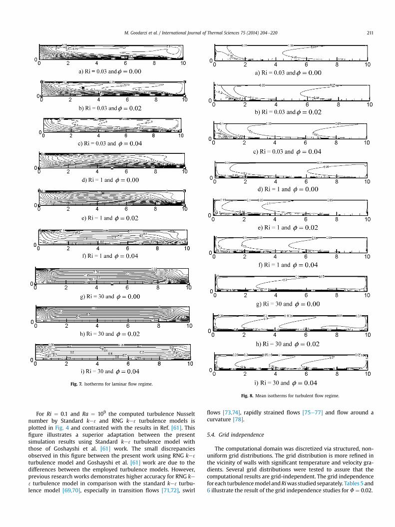
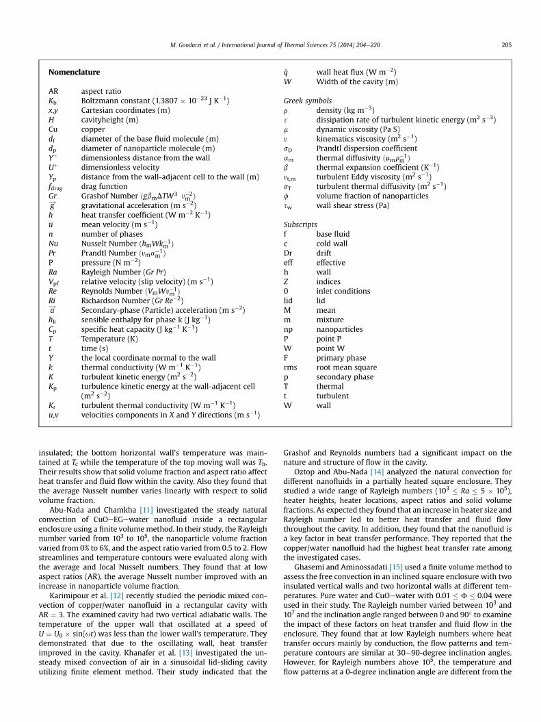
Fig. 7. Isotherms for laminar flow regime.
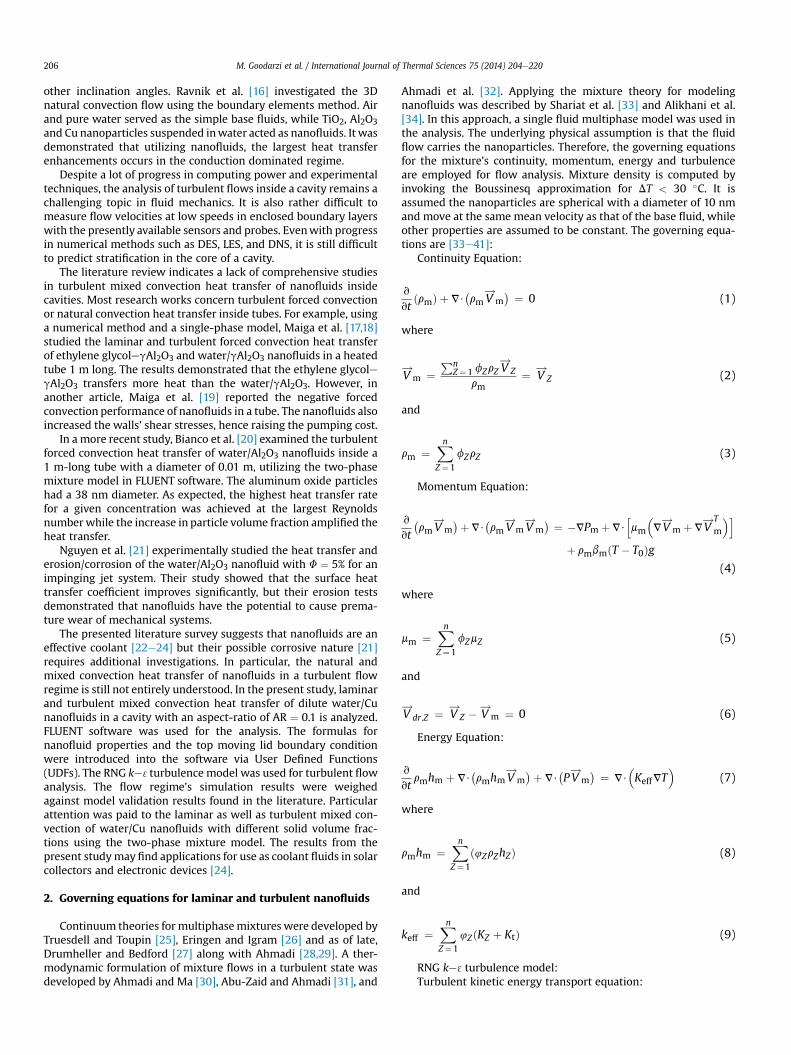
Fig. 8. Mean isotherms for turbulent flow regime.
M. Goodarzi et al. / International Journal of Thermal Sciences 75 (2014) 204e220 211
For Ri ¼ 0.1 and Ra ¼ 109 the computed turbulence Nusseltnumber by Standard ke 3 and RNG ke 3 turbulence models isplotted in Fig. 4 and contrasted with the results in Ref. [61]. Thisfigure illustrates a superior adaptation between the presentsimulation results using Standard ke 3 turbulence model withthose of Goshayshi et al. [61] work. The small discrepanciesobserved in this figure between the present work using RNG ke 3
turbulence model and Goshayshi et al. [61] work are due to thedifferences between the employed turbulence models. However,previous research works demonstrates higher accuracy for RNG ke3turbulence model in comparison with the standard ke 3turbu-lence model [69,70], especially in transition flows [71,72], swirl
flows [73,74], rapidly strained flows [75e77] and flow around acurvature [78].
5.4. Grid independence
The computational domain was discretized via structured, non-uniform grid distributions. The grid distribution is more refined inthe vicinity of walls with significant temperature and velocity gra-dients. Several grid distributions were tested to assure that thecomputational results are grid-independent. The grid independencefor each turbulencemodel andRiwasstudiedseparately. Tables 5 and6 illustrate the result of the grid independence studies for F ¼ 0.02.

Fig. 9. Turbulence Intensity representation at Y/H ¼ 0.5 for different Richardson numbers.
M. Goodarzi et al. / International Journal of Thermal Sciences 75 (2014) 204e220212
6. Results
The primary results for mixed convection within a rectangularcavity with a top moving wall are presented in this section. Apertinent dimensionless parameter here is the Richardson number,which varies from 0.03 to 30. The Richardson number is a measureof the ratio of natural convection to forced convection expressed asRi ¼ Gr/Re2. When Ri / N orRi / 0, the dominant heat transfermechanisms are free or forced convection, respectively [79]. TheGrashof number is set at 105 for laminar flow and 1010 for turbulentflow. The volume fraction of nanoparticles ranges from 0.00 to 0.04.
For calculating the dimensionless parameters, distances arenormalized by the cavity lengthW, velocities are normalized by thelid velocity Ulid, pressure is normalized by rmU2
lid and the temper-ature is normalized as T � Tc/Th � Tc [4].
6.1. Streamlines and isotherms
Figs. 5e8 illustrate the streamline and isotherm contours insidethe cavity for different Richardson numbers and various nano-particle volume fractions. In general, flow is generated by themoving upper wall. A clockwise primary (coveringmost of the area)
Fig. 10. Turbulence Kinetics Energy diagram at Y/H ¼ 0.5 for different Richardson numbers.
M. Goodarzi et al. / International Journal of Thermal Sciences 75 (2014) 204e220 213
vortex is formed inside the cavity due to the movement of thenanofluid near the upper wall. For laminar flow cases, Fig. 5 showsthat for high values of Ri, the stream function does not changeappreciably when the solid volume fractions changes.
When Ri ¼ 0.03 (Figs. 5aec) the flow field is shaped by a clock-wise eddy next to the right wall; the shear-driven flow by the lidstrongly affects the sidewall and moves downwards. However, if Riincreases and the solid volume fraction remains constant, the freeconvection inside the cavity enhances, causing the core of primaryeddy to become smaller and slightly moves to left (Fig. 5dei).
Fig. 7 shows that in the laminar flow case and for Ri ¼ 30(Fig. 7gei), the entire cavity is in a thermally stratified state which
is characterized by streamlines and isotherms that are almostparallel lines in the horizontal direction, except for the streamlinesnear the side walls. By increasing the shear force (increasing topwall velocity), the stratification disappears to some extent for Ri¼ 1(Fig. 7def) and is completely distorted for Ri ¼ 0.03 (Fig. 7aec).
For the turbulent flow case shown in Fig. 6, however, as Ri in-creases the influence of the primary eddy diminishes markedly. AtRi ¼ 0.03 (Fig.6aec) the flow field is entirely controlled by themoving upper wall, and is also sensitive to magnitude of solidvolume fraction. In this case, there is a stagnant region at the bot-tom left side of the cavity; the extent of this zone is reduced as thesolid volume fraction increases.

Fig. 11. Wall shear stress profiles for different solid volume fractions and Richardson numbers in the laminar regime.
M. Goodarzi et al. / International Journal of Thermal Sciences 75 (2014) 204e220214
In case of mixed convection (Ri ¼ 1, Fig. 6def) where forced andfree convection coexist, the stretching of the main eddy increasesdue to the cessation of free convection in the cavity with theenhanced nanofluid effective viscosity. As a result the peak value ofthe stream function decreases about 4 times compared with thatfor Ri ¼ 0.03.
For the free convection with Ri ¼ 30 (Fig. 6gei) with the bot-tom wall heated, the large eddy becomes denser, especially nearthe top and bottom walls and the peak value of the stream func-tion is about 3.5 times less than similar values for the mixedconvection state.
Among all cases studied, the strongest recirculation region wasobserved for F ¼ 0.04 and Ri ¼ 0.03, which corresponds to thehighest heat transfer augmentation.
Furthermore, the isotherms for Ri ¼ 30 shown in Fig. 8geidemonstrate the appearance of a thin thermal boundary layeraround the lower wall. Also in this state, the formation of a thin,hydrodynamic boundary layer in the direction of the moving topwall can be seen.
For the mixed convection at Ri ¼ 1 (Fig. 8def) and forced con-vection at Ri ¼ 0.03 (Fig. 8aec), it can be seen that when theRichardson number decreases, the temperature close to the left
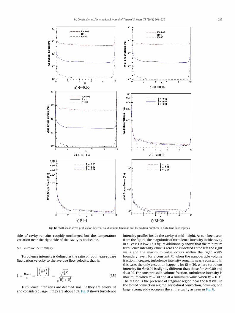
Fig. 12. Wall shear stress profiles for different solid volume fractions and Richardson numbers in turbulent flow regimes.
M. Goodarzi et al. / International Journal of Thermal Sciences 75 (2014) 204e220 215
side of cavity remains roughly unchanged but the temperaturevariation near the right side of the cavity is noticeable.
6.2. Turbulence intensity
Turbulence intensity is defined as the ratio of root mean-squarefluctuation velocity to the average flow velocity, that is:
~2 ¼ urms
u¼
��u’2�1
2
u¼
ffiffiffiffiffiffiffi23K
qffiffiffiffiffiffiffiffiffiffiffiffiffiffiffiffiffiu2x þ u2y
q (35)
Turbulence intensities are deemed small if they are below 1%and considered large if they are above 10%. Fig. 9 shows turbulence
intensity profiles inside the cavity at mid-height. As can been seenfrom the figure, the magnitude of turbulence intensity inside cavityin all cases is low. This figure additionally shows that the minimumturbulence intensity value is zero and is located at the left and rightwalls and the maximum value occurs within the right wall’sboundary layer. For a constant Ri, when the nanoparticle volumefraction increases, turbulence intensity remains nearly constant. Inthis case, the only exception happens for Ri ¼ 30, where turbulentintensity for F¼0.04 is slightly different than those for F¼0.00 andF¼0.02. For constant solid volume fraction, turbulence intensity ismaximum when Ri ¼ 30 and at a minimum value when Ri ¼ 0.03.The reason is the presence of stagnant region near the left wall inthe forced convection regime. For natural convection, however, onelarge, strong eddy occupies the entire cavity as seen in Fig. 6.

M. Goodarzi et al. / International Journal of Thermal Sciences 75 (2014) 204e220216
6.3. Turbulent kinetic energy
The model predictions for the turbulence kinetic energy profilesat mid-height are presented in Fig. 10. The calculated values indi-cate that for a constant Ri, the fluctuation kinetic energy roughlyhas a constant value, for different solid volume fractions. In allcases, the turbulence kinetic energy close to the left and right wallsincreases sharply. For constant values of solid volume fraction,Fig. 10 also shows that increasing Ri, the turbulence kinetic energydecreases. Averages of the highest and the lowest turbulence ki-netic energies are 4�10�5 m2 S�2 and 2� 10�7 m2 S�2 for Ri¼ 0.03and Ri ¼ 30 respectively.
Fig. 13. Local Nusselt number profiles for different solid volume fr
6.4. Wall shear stress
Figs. 11 and 12 show the wall shear stress variations at the hotwall for the laminar and turbulent regimes. Clearly, for a constantRi, the wall shear stress values remain roughly the same fordifferent solid volume fractions below 0.04. This is more so forlaminar flow regime compared to the turbulent flow regime. This isdue to the fact that, even though an increase of nanoparticle solidvolume fraction results in an increase in the mixture viscosity,nevertheless, for a constant Re, the velocity of the top moving walldecreases. For a constant solid volume fraction, the wall shearstress decreases as Ri increases. For laminar flow case, the
actions and Richardson numbers in the laminar flow regime.
M. Goodarzi et al. / International Journal of Thermal Sciences 75 (2014) 204e220 217
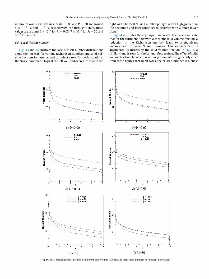
minimum wall shear stresses for Ri ¼ 0.03 and Ri ¼ 30 are around5 � 10�6 Pa and 10�8 Pa respectively. For turbulent state, thesevalues are around 4 � 10�2 for Ri ¼ 0.03, 7 � 10�3 for Ri ¼ 30 and10�5 for Ri ¼ 30.
6.5. Local Nusselt number
Figs. 13 and 14 illustrate the local Nusselt number distributionsalong the hot wall for various Richardson numbers and solid vol-ume fractions for laminar and turbulent cases. For both situations,the Nusselt number is high at the left wall and decreases toward the
Fig. 14. Local Nusselt number profiles for different solid volume
right wall. The local Nusselt number plunges with a high gradient inthe beginning and later continues to decrease with a much lowerslope.
Fig. 14 illustrates three groups of Ri curves. The curves indicatethat for the turbulent flow with a constant solid volume fraction, areduction in the Richardson number leads to a significantenhancement in local Nusselt number. This enhancement isaugmented by increasing the solid volume fraction. In Fig. 13, asimilar trend is seen for the laminar flow regime. The effect of solidvolume fraction, however, is not as prominent. It is generally clearfrom these figures that in all cases, the Nusselt number is highest
fractions and Richardson numbers in turbulent flow regime.

M. Goodarzi et al. / International Journal of Thermal Sciences 75 (2014) 204e220218
when forced convection is dominant and it is lowest when naturalconvection is dominant. As expected, the greater mixing in theturbulent flow regime enhances the heat transfer. Under similarconditions, increasing the volume fraction of nanoparticles leads togreater convective heat transfer and hence higher Nusselt numbers,since, at higher nanoparticle concentrations, the thermal conduc-tivity increases. It is also clear that when forced convection isdominant, the Nusselt number is more sensitive to an increase inthe solid volume fraction in comparison to a dominating naturalconvection condition.
6.6. Average Nusselt number
Variations of average Nusselt number versus Richardson num-ber along the hot wall for different nanoparticle volume fractions
Fig. 15. Average Nusselt number representation for different solid volume fractionsand Richardson numbers in laminar and turbulent flow regime.
are shown in Fig. 15. For all cases, the average Nusselt number isaugmented as the volume fraction increases or when theRichardson number decreases. The highest Nusselt number wasseen at 4% volume fraction and a Richardson number ¼ 0.03. Theheat transfer augmentation in this case is around 68.76% comparedto pure water. The effect of nanoparticles on heat transferenhancement in turbulent flow regime is more pronounced. Thedifferences in Nusselt number for various solid volume fractions arealso more significant when compared with those for the laminarflow regime.
7. Conclusions
A numerical study of laminar and turbulent mixed convectionheat transfer of water-based/copper (Cu) nanofluid inside a cavitywith AR ¼ 0.1 was presented. The nanofluid was simulated as atwo-phase mixture fluid and thermophysical properties of water incombination with nanoparticles were predicted utilizing theavailable models in literature. The presented mixture modelincluded the effects of shear and Brownianmotion of nanoparticles.Different solid volume fractions and Richardson numbers inlaminar and turbulent regimes were considered. The flow andtemperature fields as well as various parameters like, wall shearstress, turbulent intensity and local Nusselt number wereevaluated.
The significant observations made on the mixed convection in acavity are summarized as follows:
1) The Local Nusselt number, average Nusselt number and heattransfer coefficient of a nanofluid is augmented by increasingthe volume fraction of nanoparticles.
2) The effects of the volume fraction on turbulent kinetic energy,turbulence intensity, skin friction and wall shear stress areinsignificant.
3) At a low Richardson number (Ri ¼ 0.03), a primary clockwiseeddy forms inside the cavity. The vortex becomes smaller as theRichardson number increases.
4) For a constant Grashof number, the Nusselt number enhanceswith a decrease in the Richardson number.
5) Under similar conditions, higher Richardson numbers results inlower turbulence kinetics energies and wall shear stresses.
Acknowledgments
The authors gratefully acknowledge High Impact Research GrantUM.C/HIR/MOHE/ENG/23 and University of Malaya, Malaysia forsupport in conducting this research work.
References
[1] S.K. Das, S.U.S. Choi, W. Yu, T. Pradeep, Nanofluids: Science and Technology,Wiley Interscience, Hoboken, New Jersey, 2008.
[2] K. Khanafer, K. Vafai, Double-diffusive mixed convection in a lid-drivenenclosure filled with a fluid-saturated porous medium, Numer. Heat Transf.Part A 42 (5) (2002) 465e486.
[3] S. Chung, K. Vafai, Vibration induced mixed convection in an open-endedobstructed cavity, Int. J. Heat Mass Transf. 53 (2010) 2703e2714.
[4] M.A.R. Sharif, Laminar mixed convection in shallow inclined driven cavitieswith hot moving lid on top and cooled from bottom, Appl. Therm. Eng. 27(2007) 1036e1042.
[5] O. Manca, S. Nardini, K. Khanafer, K. Vafai, Effect of heated wall Position onmixed convection in a channel with an open cavity, Numer. Heat Transf. Part A43 (3) (2003) 259e282.
[6] O. Manca, S. Nardini, K. Vafai, Experimental investigation of mixed convectionin a channel with an open cavity, Exp. Heat Transf. 19 (1) (2006) 53e68.
[7] O. Manca, S. Nardini, K. Vafai, Experimental investigation of opposing mixedconvection in a channel with an open cavity below, Exp. Heat Transf. 21 (2)(2008) 99e114.
M. Goodarzi et al. / International Journal of Thermal Sciences 75 (2014) 204e220 219
[8] A. Marafie, K. Khanafer, B. Al-Azmi, K. Vafai, Non-darcian effects on the mixedconvection heat transfer in a metallic porous block with a confined slot jet,Numer. Heat Transf. Part A 54 (7) (2008) 665e685.
[9] W. Shi, K. Vafai, Mixed convection in an obstructed open-ended cavity,Numer. Heat Transf. Part A 57 (10) (2010) 709e729.
[10] M. Muthtamilselvan, P. Kandaswamy, J. Lee, Heat transfer enhancement ofcopperewater nanofluids in a lid-driven enclosure, Commun. Nonlinear Sci.Num. Simul. 15 (2010) 1501e1510.
[11] E. Abu-Nada, A.J. Chamkha, Effect of nanofluid variable properties on naturalconvection in enclosures filled with a CuOeEGewater nanofluid, Int. J. Therm.Sci. 49 (2010) 2339e2352.
[12] A. Karimipour, M. Afrand, M.M. Bazofti, Periodic mixed convection of ananofluid in a cavity with top lid sinusoidal motion, Int. J. Mech. Mater. Eng. 1(1) (2010) 34e39.
[13] K.M. Khanafer, A.M. Al-Amiri, I. Pop, Numerical simulation of unsteady mixedconvection in a driven cavity using an externally excited sliding lid, Eur. J.Mech. B Fluids 26 (2007) 669e687.
[14] H.F. Oztop, E. Abu-Nada, Numerical study of natural convection in partiallyheated rectangular enclosures filled with nanofluids, Int. J. Heat Fluid Flow 29(2008) 1326e1336.
[15] B. Ghasemi, S.M. Aminossadati, Natural convection heat transfer in an inclinedenclosure filled with a watereCuO nanofluid, Numer. Heat Transf. Part A 55(2009) 807e823.
[16] J. Ravnik, L. Skerget, M. Hribersek, Analysis of three-dimensional naturalconvection of nanofluids by BEM, Eng. Anal. Bound. Elem. 34 (2010) 1018e1030.
[17] S.E.B. Maiga, C.T. Nguyen, N. Galanis, G. Roy, Heat transfer behaviors ofnanofluids in a uniformly heated tube, Superlattices Microstruct. 35 (2004)543e557.
[18] S.E.B. Maiga, S.J. Palm, C.T. Nguyen, G. Roy, N. Galanis, Heat transferenhancement by using nanofluids in forced convection flows, Int. J. Heat FluidFlow 26 (4) (2005) 530e546.
[19] S.E.B. Maiga, C.T. Nguyen, N. Galanis, G. Roy, T. Maré, M. Coqueux, Heattransfer enhancement in turbulent tube flow using Al2O3 nano-particle sus-pension, Int. J. Numer. Methods Heat Fluid Flow 16 (3) (2006) 275e292.
[20] V. Bianco, O. Manca, S. Nardini, Numerical simulation of water/Al2O3 nano-fluid turbulent convection, Adv. Mech. Eng. (2010) 1e10.
[21] C.T. Nguyen, G. Laplante, M. Curyand, G. Simon, Experimental investigation ofimpinging jet heat transfer and erosion effect using Al2O3/water nanofluid, in:6th IASME/WSEAS Int. Conf. Fluid Mech. Aerodyn. (FMA’08), Rhodes, Greece,2008.
[22] K.Y. Leong, R. Saidur, S.N. Kazi, A.H. Mamun, Performance investigation of anautomotive car radiator operated with nanofluid-based coolants (nanofluid asa coolant in a radiator), Appl. Therm. Eng. 30 (2010) 2685e2692.
[23] K.Y. Leong, R. Saidur, T.M.I. Mahlia, Y.H. Yau, Modeling of shell and tube heatrecovery exchanger operated with nanofluid based coolants, Int. J. Heat MassTransf. 55 (2012) 808e816.
[24] A. Ijam, R. Saidur, Nanofluids as a Coolant for Electronic Devices, Lap LambertAcademic Publishing, 2012.
[25] C. Truesdell, R.A. Toupin, The classical field theories, in: S. Flugge (Ed.), Handb.Phys, vol. III/I, Springer Verlag, Berlin, 1960.
[26] A.C. Eringen, J.D. Igram, A continuum theory of chemically reacting media-II,Int. J. Eng. Sci. 3 (1965) 147e212.
[27] D.S. Drumheller, A. Bedford, A thermodynamical theory for reacting immis-cible mixtures, Arch. Ration. Mech. Anal 73 (1980) 257e284.
[28] G. Ahmadi, Mechanics of saturated granular materials, Int. J. Nonlinear Mech.15 (1980) 251e262.
[29] G. Ahmadi, On mechanics of incompressible multiphase suspensions, Adv.Water Resour. 10 (1987) 32e43.
[30] G. Ahmadi, D. Ma, A thermodynamical formulation for dispersed multiphaseturbulent flows, part I: basic theory, Int. J. Multiph. Flow 16 (1990) 323e340.
[31] S. Abu-Zaid, G. Ahmadi, A thermodynamically consistent rate-dependentmodel for turbulent two-phase flows, Int. J. Nonlinear Mech. 30 (1995)509e529.
[32] G. Ahmadi, J. Cao, L. Schneider, A. Sadiki, A thermodynamic formulationfor chemically active multiphase turbulent flows, Int. J. Eng. Sci. 44 (2006)699e720.
[33] M. Shariat, A. Akbarinia, A. Hossein Nezhad, A. Behzadmehr, R. Laur, Nu-merical study of two phase laminar mixed convection nanofluid in ellipticducts, Appl. Therm. Eng. 31 (2011) 2348e2359.
[34] S. Alikhani, A. Behzadmehr, M. Saffar-Avval, Numerical study of nanofluidmixed convection in a horizontal curved tube using two-phase approach, HeatMass Transf. 47 (2011) 107e118.
[35] M. Izadi, A. Behzadmehr, D. Jalali-Vahida, Numerical study of developinglaminar forced convection of a nanofluid in an annulus, Int. J. Therm. Sci. 48(2009) 2119e2129.
[36] O. Ghaffari, A. Behzadmehr, H. Ajam, Turbulent mixed convection of a nano-fluid in a horizontal curved tube using a two-phase approach, Int. Commun.Heat Mass Transf. 37 (2010) 1551e1558.
[37] R. Lotfi, Y. Saboohi, A.M. Rashidi, Numerical study of forced convective heattransfer of nanofluids: comparison of different approaches, Int. Commun. HeatMass Transf. 37 (2010) 74e78.
[38] R. Mokhtari Moghari, A. Akbarinia, M. Shariat, F. Talebi, R. Laur, Two phasemixed convection Al2O3ewater nanofluid flow in an annulus, Int. J. Multiph.Flow 37 (2011) 585e595.
[39] V. Bianco, S. Nardini, O. Manca, Enhancement of heat transfer and entropygeneration analysis of nanofluids turbulent convection flow in square sectiontubes, Nanoscale Res. Lett. 6 (2011) 252.
[40] M. Akbari, N. Galanis, A. Behzadmehr, Comparative assessment of single andtwo-phase models for numerical studies of nanofluid turbulent forced con-vection, Int. J. Heat Fluid Flow 37 (2012) 136e146.
[41] M. Nuim Labib, Md. J. Nine, H. Afrianto, H. Chung, H. Jeong, Numericalinvestigation on effect of base fluids and hybrid nanofluid in forced convectiveheat transfer, Int. J. Therm. Sci. 71 (2013) 163e171.
[43] D. Choudhury, Introduction to the Renormalization Group Method and Tur-bulence Modeling, Fluent Inc. Tech, 1993. Memorandum TM-107.
[44] J.D. Posner, C.R. Buchanan, D. Dunn-Rankin, Measurement and prediction ofindoor air flow in a model room, Energy Build. 35 (2003) 515e526.
[45] A. Guardo, M. Coussirat, M.A. Larrayoz, F. Recasens, E. Egusquiza, Influence ofthe turbulence model in CFD modeling of wall-to-fluid heat transfer in packedbeds, Chem. Eng. Sci. 60 (6) (2005) 1733e1742.
[46] K. Mansour, M. Yahyazade, Effects of turbulence model in computational fluiddynamics of horizontal axis wind turbine aerodynamic, WSEAS Trans. Appl.Theor. Mech. 3 (6) (2011) 108e118.
[47] M.R. Safaei, Y. Maghmoumi, A. Karimipour, Numerical investigation of tur-bulence mixed convection heat transfer of water and drilling mud inside asquare enclosure by finite volume method, in: 4th Int. Meet. Adv. Thermo-fluids, IMAT 2011; Melaka, Malaysia, 2011.
[48] B. Ghasemi, S.M. Aminossadati, Periodic natural convection in ananofluid-filled enclosure with oscillating heat flux, Int. J. Therm. Sci. 49(2010) 1e9.
[49] A. Ramiar, A.A. Ranjbar, S.F. Hosseinizadeh, Effect of axial conduction andvariable properties on two dimensional conjugate heat transfer of Al2O3eEG/water mixture nanofluid in microchannel, J. Appl. Fluid Mech. 5 (3) (2012)79e87.
[50] K. Khanafer, K. Vafai, A critical synthesis of thermophysical characteristics ofnanofluids, Int. J. Heat Mass Transf. 54 (2011) 4410e4428.
[51] C.H. Chon, K.D. Kihm, S.P. Lee, S.U.S. Choi, Empirical correlation finding therole of temperature and particle size for nanofluid (Al2O3) thermal conduc-tivity enhancement, J. Appl. Phys. 87 (15) (2005) 153107e153107-3.
[52] H.A. Mintsa, G. Roy, C.T. Nguyen, D. Doucet, New temperature dependentthermal conductivity data for water-based nanofluids, Int. J. Therm. Sci. 48(2009) 363e371.
[53] N. Masoumi, N. Sohrabi, A. Behzadmehr, A new model for calculating theeffective viscosity of nanofluids, J. Phys. D Appl. Phys. 42 (2009) 055501e055506.
[54] K. Khanafer, K. Vafai, M. Lightstone, Buoyancy-driven heat transfer enhance-ment in a two-dimensional enclosure utilizing nanofluids, Int. J. Heat MassTransf. 46 (2003) 3639e3653.
[55] O. Abouali, G. Ahmadi, Computer simulations of natural convection of singlephase nanofluids in simple enclosures: a critical review, Appl. Therm. Eng. 36(2012) 1e13.
[56] B.E. Launder, D.B. Spalding, The numerical computation of turbulent flows,Comput. Methods Appl. Mech. Eng. 3 (1974) 269e289.
[57] E. Abedini, A. Behzadmehr, S.M.H. Sarvari, S.H. Mansouri, Numerical investi-gation of subcooled flow boiling of a nanofluid, Int. J. Therm. Sci. 64 (2013)232e239.
[58] S.V. Patankar, Numerical Heat Transfer and Fluid Flow, Hemisphere, Wash-ington, 1980.
[59] M.R. Safaei, H.R. Goshayshi, B. Saeedi Razavi, M. Goodarzi, Numerical inves-tigation of laminar and turbulent mixed convection in a shallow water-filledenclosure by various turbulence methods, Sci. Res. Essays 6 (22) (2011) 4826e4838.
[60] M.R. Safaei, B. Rahmanian, M. Goodarzi, Numerical study of laminar mixedconvection heat transfer of power-law non-Newtonian fluids in squareenclosures by finite volume method, Int. J. Phys. Sci. 6 (33) (2011) 7456e7470.
[61] H.R. Goshayshi, M.R. Safaei, Y. Maghmoumi, Numerical simulation of unsteadyturbulent and laminar mixed convection in rectangular enclosure with hotupper moving wall by finite volume method, in: 6th Int. Chem. Eng. Congr.Exhib. (Ichec 2009), Kish Island, Iran, 2009.
[62] S. Mirmasoumi, A. Behzadmehr, Effect of nanoparticles mean diameter onmixed convection heat transfer of a nanofluid in a horizontal tube, Int. J. HeatFluid Flow 29 (2008) 557e566.
[63] M. Akbari, A. Behzadmehr, F. Shahraki, Fully developed mixed convection inhorizontal and inclined tubes with uniform heat flux using nanofluid, Int. J.Heat Fluid Flow 29 (2008) 545e556.
[64] A. Karimipour, M. Afrand, M. Akbari, M.R. Safaei, Simulation of fluid flow andheat transfer in the inclined enclosure, in: Int. Conf. Fluid Dyn. Thermodyn.(ICFDT 2012). Zurich, Switzerland, 2012.
[65] F. Ampofo, T.G. Karayiannis, Experimental benchmark data for turbulentnatural convection in an air filled square cavity, Int. J. Heat Mass Transf. 46(2003) 3551e3572.
[66] S.H. Peng, L. Davidson, Large eddy simulation for turbulent buoyant flow in aconfined cavity, Int. J. Heat Fluid Flow 22 (2001) 323e331.
[67] M. Omri, N. Galanis, Numerical analysis of turbulent buoyant flows in en-closures: influence of grid and boundary conditions, Int. J. Therm. Sci. 46(2007) 727e738.
[68] K.J. Hsieh, F.S. Lien, Numerical modeling of buoyancy-driven turbulent flowsenclosures, Int. J. Heat Fluid Flow 25 (2004) 659e670.

M. Goodarzi et al. / International Journal of Thermal Sciences 75 (2014) 204e220220
[69] A. Abdel Wahab, E.E. Khalil, Mathematical modeling of turbulent flows infurnaces, in: 6th Int. Energy Convers. Eng. Conf. (IECEC), Cleveland, Ohio,U.S.A., 2008, pp. 1239e1248.
[70] A.S. Yadav, J.L. Bhagoria, Heat transfer and fluid flow analysis of solar airheater: a review of CFD approach, Renew. Sustain. Energy Rev. 23 (2013)60e79.
[71] C.M. Teixeira, Incorporating turbulence models into the LatticeeBoltzmannmethod, Int. J. Mod. Phys. C 09 (08) (1998) 1159e1175.
[72] K. Saha, S.N. Singh, V. Seshadri, S. Mukhopadhyay, Computational analysis onflow through transition s-diffusers: effect of inlet shape, J. Aircr. 44 (1) (2007)187e193.
[73] K. Hanjalic, Advanced turbulence closure models: a view of current status andfuture prospects, Int. J. Heat Fluid Flow 15 (3) (1994) 178e203.
[74] O. Kaario, M. Larmi, F. Tanner, Relating integral length scale to turbulent timescale and comparing ke 3and RNG ke 3turbulence models in diesel combus-tion simulation, in: SAE 2002 World Congr. & Exh., Detroit, Michigan, UnitedStates, U.S.A, 2002, pp. 2002-01-1117.
[75] S.S. Vargheseand, S.H. Frankel, Numerical modeling of pulsatile turbulent flowin Stenotic Vessels, J. Biomech. Eng. 125 (2003) 445e460.
[76] M. Hidayat, A. Rasmuson, Numerical assessment of gasesolid flow in a U-bend, IchemE Trans. Part A Chem. Eng. Res. Des. 82 (A3) (2004) 332e343.
[77] S.M. El-Behery, M.H. Hamed, M.A. El-Kadi, K.A. Ibrahim, CFD prediction of airesolid flow in 180� curved duct, Powder Technol. 191 (2009) 130e142.
[78] T.B. Gatski, M.Y. Hussaini, J.L. Lumley, Simulation and Modeling of TurbulentFlows, Oxford University Press, New York, U.S.A., 1996.
[79] A. Bejan, Heat Transfer, John Wiley & Sons, New Jersey, 1993.