international standard 10441
TRANSCRIPT

Reference numberISO 10441:2007(E)
© ISO 2007
INTERNATIONAL STANDARD
ISO10441
Second edition2007-03-15
Petroleum, petrochemical and natural gas industries — Flexible couplings for mechanical power transmission — Special-purpose applications
Industries du pétrole, de la pétrochimie et du gaz naturel — Accouplements flexibles pour transmission de puissance mécanique — Applications spéciales
Licensed to: Vernikovsky, Vladimir MrDownloaded: 2020-09-11Single user licence only, copying and networking prohibited

ISO 10441:2007(E)
PDF disclaimer This PDF file may contain embedded typefaces. In accordance with Adobe's licensing policy, this file may be printed or viewed but shall not be edited unless the typefaces which are embedded are licensed to and installed on the computer performing the editing. In downloading this file, parties accept therein the responsibility of not infringing Adobe's licensing policy. The ISO Central Secretariat accepts no liability in this area.
Adobe is a trademark of Adobe Systems Incorporated.
Details of the software products used to create this PDF file can be found in the General Info relative to the file; the PDF-creation parameters were optimized for printing. Every care has been taken to ensure that the file is suitable for use by ISO member bodies. In the unlikely event that a problem relating to it is found, please inform the Central Secretariat at the address given below.
© ISO 2007 All rights reserved. Unless otherwise specified, no part of this publication may be reproduced or utilized in any form or by any means, electronic or mechanical, including photocopying and microfilm, without permission in writing from either ISO at the address below or ISO's member body in the country of the requester.
ISO copyright office Case postale 56 • CH-1211 Geneva 20 Tel. + 41 22 749 01 11 Fax + 41 22 749 09 47 E-mail [email protected] Web www.iso.org
Published in Switzerland
ii © ISO 2007 – All rights reserved
Licensed to: Vernikovsky, Vladimir MrDownloaded: 2020-09-11Single user licence only, copying and networking prohibited

ISO 10441:2007(E)
© ISO 2007 – All rights reserved iii
Contents Page
Foreword............................................................................................................................................................. v Introduction ....................................................................................................................................................... vi 1 Scope ......................................................................................................................................................1 2 Normative references ............................................................................................................................1 3 Terms and definitions ...........................................................................................................................2 4 Statutory requirements .........................................................................................................................7 5 Coupling selection.................................................................................................................................7 6 Coupling design.....................................................................................................................................9 7 Coupling ratings ..................................................................................................................................11 8 Coupling requirements .......................................................................................................................12 8.1 Metallic flexible-element couplings ...................................................................................................12 8.2 Machining .............................................................................................................................................12 8.3 Spacer ...................................................................................................................................................13 8.4 Hub type................................................................................................................................................13 8.5 Integral flanges ....................................................................................................................................13 8.6 Hubs ......................................................................................................................................................13 8.7 Solo plate (idling adapter)...................................................................................................................15 8.8 Moment simulator ................................................................................................................................15 8.9 Component fit tolerances and potential unbalance calculations ...................................................15 8.10 Fasteners (including studs)................................................................................................................15 8.11 Electrical insulation.............................................................................................................................16 8.12 Dynamics ..............................................................................................................................................16 9 Balance .................................................................................................................................................17 9.1 General..................................................................................................................................................17 9.2 Balancing methods..............................................................................................................................18 9.3 Balance criteria ....................................................................................................................................20 9.4 Trim balance holes ..............................................................................................................................23 10 Materials ...............................................................................................................................................24 11 Accessories..........................................................................................................................................24 12 Manufacturing quality, inspection, testing and preparation for shipment ....................................25 12.1 Manufacturing quality .........................................................................................................................25 12.2 Inspection and testing.........................................................................................................................25 12.3 Inspection .............................................................................................................................................26 12.4 Testing ..................................................................................................................................................26 12.5 Preparation for shipment ....................................................................................................................27 13 Vendor data ..........................................................................................................................................27 13.1 General..................................................................................................................................................27 13.2 Proposals and contract data ..............................................................................................................28 Annex A (normative) Torsional damping couplings and resilient couplings .............................................31 Annex B (normative) Gear couplings..............................................................................................................34 Annex C (normative) Quill-shaft couplings ....................................................................................................36 Annex D (informative) Factors for metallic element couplings ....................................................................37 Annex E (informative) Example of the determination of potential unbalance ............................................39
Licensed to: Vernikovsky, Vladimir MrDownloaded: 2020-09-11Single user licence only, copying and networking prohibited

ISO 10441:2007(E)
iv © ISO 2007 – All rights reserved
Annex F (informative) Examples of misalignments ...................................................................................... 43 Annex G (informative) Coupling tapers .......................................................................................................... 44 Annex H (normative) Coupling guards........................................................................................................... 45 Annex I (informative) Procedure for residual unbalance check .................................................................. 47 Annex J (informative) Coupling datasheets................................................................................................... 51 Bibliography ..................................................................................................................................................... 56
Licensed to: Vernikovsky, Vladimir MrDownloaded: 2020-09-11Single user licence only, copying and networking prohibited

ISO 10441:2007(E)
© ISO 2007 – All rights reserved v
Foreword
ISO (the International Organization for Standardization) is a worldwide federation of national standards bodies (ISO member bodies). The work of preparing International Standards is normally carried out through ISO technical committees. Each member body interested in a subject for which a technical committee has been established has the right to be represented on that committee. International organizations, governmental and non-governmental, in liaison with ISO, also take part in the work. ISO collaborates closely with the International Electrotechnical Commission (IEC) on all matters of electrotechnical standardization.
International Standards are drafted in accordance with the rules given in the ISO/IEC Directives, Part 2.
The main task of technical committees is to prepare International Standards. Draft International Standards adopted by the technical committees are circulated to the member bodies for voting. Publication as an International Standard requires approval by at least 75 % of the member bodies casting a vote.
Attention is drawn to the possibility that some of the elements of this document may be the subject of patent rights. ISO shall not be held responsible for identifying any or all such patent rights.
ISO 10441 was prepared by Technical Committee ISO/TC 67, Materials, equipment and offshore structures for petroleum, petrochemical and natural gas industries, Subcommittee SC 6, Processing equipment and systems.
This second edition cancels and replaces the first edition (ISO 10441:1999), which has been technically revised.
Licensed to: Vernikovsky, Vladimir MrDownloaded: 2020-09-11Single user licence only, copying and networking prohibited

ISO 10441:2007(E)
vi © ISO 2007 – All rights reserved
Introduction
This International Standard was developed from the API Std 671, 3rd edition, 1998. It is intended that the 4th edition of API Std 671 will be identical to this International Standard.
Users of this International Standard should be aware that further or differing requirements may be needed for individual applications. This International Standard is not intended to inhibit a vendor from offering, or the purchaser from accepting alternative equipment or engineering solutions for the individual application. This may be particularly appropriate where there is innovative or developing technology. Where an alternative is offered, the vendor should identify any variations from this International Standard and provide details.
This International Standard requires the purchaser to specify certain details and features.
A bullet (●) at the beginning of a subclause or paragraph indicates that either a decision is required or further information is to be provided by the purchaser. This information should be indicated on the datasheet(s), typical examples of which are included as Annex J; otherwise it should be stated in the quotation request or in the order.
Licensed to: Vernikovsky, Vladimir MrDownloaded: 2020-09-11Single user licence only, copying and networking prohibited
INTERNATIONAL STANDARD ISO 10441:2007(E)
© ISO 2007 – All rights reserved 1
Petroleum, petrochemical and natural gas industries — Flexible couplings for mechanical power transmission — Special-purpose applications
1 Scope
This International Standard specifies the requirements for couplings for the transmission of power between the rotating shafts of two machines in special-purpose applications in the petroleum, petrochemical and natural gas industries. Such applications are typically in large and/or high speed machines, in services that can be required to operate continuously for extended periods, are often unspared and are critical to the continued operation of the installation. By agreement, it can be used for other applications or services.
Couplings covered by this International Standard are designed to accommodate parallel (or lateral) offset, angular misalignment and axial displacement of the shafts without imposing unacceptable mechanical loading on the coupled machines. It is applicable to gear, metallic flexible element, quill shaft and torsionally resilient type couplings. Torsional damping and resilient type couplings are detailed in Annex A; gear-type couplings are detailed in Annex B and quill shaft style couplings are detailed in Annex C.
This International Standard covers the design, materials of construction, manufacturing quality, inspection and testing of special-purpose couplings.
This International Standard does not define criteria for the selection of coupling types for specific applications.
This International Standard is not applicable to other types of couplings, such as clutch, hydraulic, eddy-current, rigid, radial spline, chain and bellows types.
2 Normative references
The following referenced documents are indispensable for the application of this document. For dated references, only the edition cited applies. For undated references, the latest edition of the referenced document (including any amendments) applies.
ISO 262, ISO general-purpose metric screw threads — Selected sizes for screws, bolts and nuts
ISO 286-2, ISO system of limits and fits — Part 2: Tables of standard tolerance grades and limit deviations for holes and shafts
ISO 2491, Thin parallel keys and their corresponding keyways (Dimensions in millimetres)
ANSI Y14.2M1), Line Conventions and Lettering
ANSI/AGMA 90002), Flexible Couplings — Potential Unbalance Classification
ANSI/AGMA 9002, Bores and Keyways for Flexible Couplings (Inch Series)
ANSI/AGMA 9003, Flexible Couplings — Keyless Fits
1) American National Standards Institute, 25 West 43rd Street, 4th Floor, New York, NY 10036, USA.
2) American Gear Manufacturers Association, 500 Montgomery Street, Suite 350, Alexandria, VA 22314-1560, USA.
Licensed to: Vernikovsky, Vladimir MrDownloaded: 2020-09-11Single user licence only, copying and networking prohibited

ISO 10441:2007(E)
2 © ISO 2007 – All rights reserved
ANSI/AGMA 9004, Flexible Couplings — Mass Elastic Properties and other Characteristics (Inch Series)
ANSI/AGMA 9104, Flexible Couplings — Mass Elastic Properties and other Characteristics (Metric Series)
ANSI/AGMA 9112, Bores and Keyways for Flexible Couplings (Metric Series)
ANSI/ASME B1.13), Unified inch screw threads, UN and UNR thread form
DIN 71904), Interference fits — Calculation and design rules
3 Terms and definitions
For the purposes of this document, the following terms and definitions apply.
3.1 angular misalignment ⟨double-engagement couplings⟩ two minor angles between the extension of each machine centreline and the centreline of the structure joining the two flexible elements
3.2 angular misalignment ⟨single-engagement couplings⟩ minor angle between the extensions of two machine-shaft centrelines
NOTE If the shaft centrelines do not intersect, a single-engagement coupling is not appropriate.
3.3 assembly balance procedure in which a completely assembled coupling is balanced as a unit
3.4 assembly balance check procedure in which an assembled coupling is placed on a balancing machine and the residual unbalance is measured
NOTE An assembly balance check can be carried out on a component balanced coupling, or on an assembly-balanced coupling.
3.5 axial displacement change in the relative axial position of the adjacent shaft ends of two coupled machines, usually caused by thermal expansion
3.6 component balance procedure for achieving coupling balance in which the components or factory assembled sub-assemblies are balanced separately before assembly of the coupling
3.7 continuous torque rating coupling manufacturer’s declared maximum torque that the coupling is capable of transmitting continuously for unlimited periods
3) ASME International, Three Park Avenue, New York, NY 10016-5990, USA.
4) Deutsches Institut fur Normung, Burggrafenstrasse 6, Sresemannallee 15, Berlin, Germany D-10787.
Licensed to: Vernikovsky, Vladimir MrDownloaded: 2020-09-11Single user licence only, copying and networking prohibited
ISO 10441:2007(E)
© ISO 2007 – All rights reserved 3
3.8 crown diameter major diameter of the external teeth of a gear-type coupling
3.9 distance between shaft ends DBSE distance from the extreme end of one shaft (including any threaded end) to the extreme end of the next shaft or, in the case of integral flanges, the distance from the mating faces
3.10 double engagement coupling coupling with two planes of flexure
NOTE This arrangement enables couplings of certain types, notably gear and metallic flexible element types, that cannot normally accommodate parallel (or lateral) offset, to do so.
3.11 factor of safety factor that is used to cover uncertainties in a coupling design
EXAMPLES Analytical assumptions in stress analysis, material properties, manufacturing tolerances, etc.
NOTE Under given design conditions, the factor of safety is the material yield strength divided by the calculated stress, where the stress is a function of torque, speed, misalignment and axial displacement.
3.12 fatigue factor of safety factor of safety at the published continuous rated conditions of torque, speed, misalignment and axial displacement, used by the manufacturer to establish the coupling rating
See 7.1.
NOTE The fatigue factor of safety is further explained and defined in Annex D.
3.13 flex-hub coupling gear-type coupling with the external teeth on the hubs and the internal teeth in the sleeves
3.14 gear coupling coupling of the mechanical contact type that transmits torque and accommodates angular misalignment, parallel offset and axial displacement by relative rocking and sliding motion between mating, profiled gear teeth
3.15 half coupling composite of all of the components of the coupling attached to, and supported from, one shaft including an appropriate portion of the spacer assembly in the case of a double-engagement coupling or of the flexing elements of a single-engagement coupling
3.16 idling adapter solo plate device designed to rigidly hold in alignment the floating parts of certain types of couplings to allow uncoupled operation of the driving or driven machine without dismounting the coupling hub
Licensed to: Vernikovsky, Vladimir MrDownloaded: 2020-09-11Single user licence only, copying and networking prohibited

ISO 10441:2007(E)
4 © ISO 2007 – All rights reserved
3.17 lateral offset lateral distance between the centrelines of two shafts, which are not parallel, measured perpendicularly to the centreline and in the plane of the shaft end of the driving machine
See Annex F.
3.18 manufacturer agency responsible for the design and fabrication of the coupling
NOTE The manufacturer is not necessarily the vendor.
3.19 maximum allowable temperature maximum continuous temperature for which the manufacturer has designed the coupling
3.20 maximum continuous angular misalignment maximum angular misalignment at each plane of flexure that the coupling is able to tolerate for unlimited periods
NOTE Maximum continuous angular misalignment can be expressed as either
a) a single value when transmitting the coupling continuous torque rating at the coupling rated speed, and simultaneously subjected to the coupling maximum continuous axial displacement, or
b) a range of values expressed as an inter-related function of speed, torque, and axial displacement.
3.21 maximum continuous axial displacement maximum axial displacement the coupling is able to tolerate for unlimited periods
NOTE Maximum continuous axial displacement can be expressed as either
a) a single value when transmitting the coupling continuous torque rating at the coupling rated speed and simultaneously subjected to the coupling maximum continuous angular misalignment, or
b) a range of values expressed as an inter-related function of speed, torque, and angular misalignment.
3.22 maximum continuous speed highest rotational speed at which the coupling, as made and tested, is capable of continuous operation
3.23 metallic flexible-element coupling coupling type that obtains its flexibility from the flexing of thin metallic discs, diaphragms or links
3.24 moment simulator auxiliary device intended to simulate the moment of the mass of a half coupling
NOTE A moment simulator can also be designed to serve as an idling adapter (solo plate).
3.25 momentary torque limit torque that corresponds to a factor of safety of 1,0 with respect to the most highly stressed component’s material yield strength, allowing for a combination of speed, angular misalignment and axial displacement
Licensed to: Vernikovsky, Vladimir MrDownloaded: 2020-09-11Single user licence only, copying and networking prohibited
ISO 10441:2007(E)
© ISO 2007 – All rights reserved 5
3.26 normal operating point point at which usual operation is expected
NOTE This point is usually the point at which the machine manufacturer(s) certify(ies) that performance is within the tolerances stated to the owner.
3.27 owner final recipient of the equipment, who may delegate another agent as the purchaser of the equipment
3.28 parallel offset distance between the centrelines of two coupled shafts that are parallel but not in the same straight line
See Annex F.
3.29 peak torque rating maximum torque the coupling can tolerate for short periods
3.30 pilot rabbet register surface that positions a coupling component, sub-assembly, or assembly radially with respect to another coupling component
3.31 potential unbalance probable net unbalance of a complete coupling
NOTE 1 Potential unbalance results from a combination of the residual unbalance of individual components and sub-assemblies and possible eccentricity of the components and sub-assemblies due to run-out and tolerances of the various surfaces and registers. Since it can be assumed that the actual values of the various contributory unbalances are random in both magnitude and direction, the numerical value of the potential unbalance is the square root of the sum of the squares of all the contributory unbalances. Typical contributory unbalances are
a) the residual unbalance of each component or sub-assembly,
b) errors in the balance of each component or sub-assembly resulting from eccentricity in the fixture used to mount the component or sub-assembly in the balance machine,
c) the unbalance of each component or sub-assembly due to eccentricity resulting from clearance or run-out of the relevant registers or fits.
NOTE 2 The concept of potential unbalance is explained more fully and a worked example is provided in Annex E.
3.32 purchaser agency that issues the order and the specification to the vendor
NOTE The purchaser can be the owner of the plant in which the equipment is to be installed, the owner’s appointed agent or, frequently, the manufacturer of the driven machine.
3.33 quill-shaft coupling coupling that is both laterally and torsionally flexible, with angular misalignment, parallel offset and torsional fluctuations being accommodated by elastic deformation of a relatively long, slender shaft
NOTE Quill-shaft couplings, unless combined with another type, cannot accommodate axial displacement.
Licensed to: Vernikovsky, Vladimir MrDownloaded: 2020-09-11Single user licence only, copying and networking prohibited
ISO 10441:2007(E)
6 © ISO 2007 – All rights reserved
3.34 rated speed highest rotational speed at which the coupling is required to be capable of transmitting the continuous torque rating while simultaneously subjected to the rated angular misalignment and the coupling rated axial displacement
3.35 residual unbalance level of unbalance remaining in a component or assembly after it has been balanced, either to the limit of the capability of the balancing machine or in accordance with the relevant standard
3.36 service factor factor applied to the steady-state torque in order to allow for off-design conditions, cyclic and other variations as well as equipment variations resulting in higher torque than that at the equipment normal operating point
NOTE Service factor is not the same as the factor of safety, 3.11 or the fatigue factor of safety, 3.12.
3.37 single-engagement coupling coupling with only one plane of flexure
NOTE This type of coupling can accommodate angular misalignment and axial displacement. Single-engagement couplings of some types, notably gear and metallic flexible element types, do not normally accommodate parallel (or lateral) offset. Certain types of single-engagement couplings (not covered by this International Standard) can accommodate offset misalignment to a limited extent.
3.38 spacer part of a coupling that is removable to give access for maintenance and/or removal of the coupling hubs
NOTE The spacer can be a single component or an assembly.
3.39 spacer gap length distance between coupling hubs or sleeves in which the coupling spacer is installed
NOTE Spacer gap length is not necessarily equal to the distance between the shaft ends.
3.40 torsional damping absorption or dissipation of oscillatory rotary energy
NOTE Torsional damping is necessary in some cases to limit the build-up of steady-state torsional resonant oscillations in a system.
3.41 torsional natural frequency frequency of the undamped, free-rotational vibration of a system composed of revolving mass inertias acting in combination with the restraining torsional rigidities of the connected shafts and couplings
3.42 torsionally resilient coupling coupling with increased flexibility in a rotational direction, increased capability to recover from flexing and with hysteresis capability
NOTE Resilience is the ability to recover from deformation under repeated flexing, taking account of energy storage and hysteresis effects. Some types of torsionally resilient couplings can also be designed to accommodate misalignment and/or axial displacement.
Licensed to: Vernikovsky, Vladimir MrDownloaded: 2020-09-11Single user licence only, copying and networking prohibited
ISO 10441:2007(E)
© ISO 2007 – All rights reserved 7
3.43 torsional stiffness ratio of the applied torque to the resulting torsional displacement of either a complete coupling or part of the coupling, such as a spacer
NOTE With some types of couplings, the torsional stiffness is not constant but is a function of the magnitude of the torque and, with oscillating torques, also the frequency.
3.44 total indicator reading TIR difference between the maximum and minimum readings of a dial indicator or similar device, monitoring a face or cylindrical surface during one complete revolution of the monitored surface
NOTE 1 For a perfectly cylindrical surface, the total indicator reading implies an eccentricity equal to half the reading. For a perfectly flat face, the total indicator reading implies an out-of-squareness equal to the reading. If the surface in question is not perfectly cylindrical or flat, the interpretation of the meaning of total indicator reading is more complex and can represent ovality or lobing.
NOTE 2 Total indicator reading is also known as “full indicator movement”.
3.45 unit responsibility responsibility for co-ordinating the delivery and technical aspects of the equipment and all auxiliary systems included in the scope of the order
NOTE The technical aspects to be considered include, but are not limited to, such factors as the power requirements, speed, rotation, general arrangement, dynamics, noise, lubrication, sealing system, material test reports, instrumentation, piping, conformance to specifications and testing of components.
3.46 vendor supplier agency that supplies the equipment
NOTE The vendor is the manufacturer of the equipment or the manufacturer’s agent and normally is responsible for service support.
4 Statutory requirements
The purchaser and the vendor shall mutually determine the measures to be taken to comply with any federal, state or local codes, regulations, ordinances or rules that are applicable to the equipment.
5 Coupling selection
5.1 The purchaser shall specify the type of coupling required. Unless otherwise specified, the coupling shall be a metallic flexible-element coupling. For torsional damping and resilient couplings, refer to Annex A; for gear couplings, refer to Annex B; and for quill-shaft couplings, refer to Annex C.
5.2 The coupling shall be selected based on the equipment loading and shall be capable of transmitting the maximum steady-state torques, cyclic torques, and the maximum transient torques under all conditions of angular misalignment, axial displacement, speed and temperature, simultaneously, to which it will be subjected in service.
In general, a special-purpose coupling shall be designed and constructed for a minimum service life of five years for flexible element couplings and three years for gear and torsional damping and resilient couplings.
Figure 1 provides guidance for the typical selection process for a coupling.
5.3 If specified, the coupling, coupling-to-shaft juncture and shafting may be sized for a future condition. Licensed to: Vernikovsky, Vladimir MrDownloaded: 2020-09-11Single user licence only, copying and networking prohibited

ISO 10441:2007(E)
8 © ISO 2007 – All rights reserved
Figure 1 — Typical coupling selection process
Licensed to: Vernikovsky, Vladimir MrDownloaded: 2020-09-11Single user licence only, copying and networking prohibited

ISO 10441:2007(E)
© ISO 2007 – All rights reserved 9
6 Coupling design
6.1 The purchaser shall specify the following requirements, where applicable:
a) type of train;
b) normal power;
c) normal speed and variations;
d) maximum continuous speed;
e) any defined overspeed;
f) angular misalignment;
g) axial displacements;
h) shaft sizes and styles;
i) distance between shaft-ends;
j) temperature;
k) type of driver;
l) driver power rating (list and driver service factor);
m) expected transient (peak) and cyclic torque conditions, including magnitude, nature and number of occurrences of transients to which the coupling will be subjected in service.
6.2 The purchaser shall specify the maximum angular misalignments the coupling is expected to experience during start-up, normal operation and shut-down of the coupled machines, normally expressed as parallel (or lateral) offset and/or angular misalignment between the coupled shafts. These values shall allow for all the known effects on the machines from thermal, pressure and dynamic forces. Unless otherwise specified, the steady-state angular misalignment capability across each flexible element shall be not less than 0,2°.
6.3 The purchaser shall specify the maximum axial displacements the coupling is expected to experience, expressed as the amount and direction of the relative movement of the shaft ends toward or away from each other as the coupled machines go through their start-up, normal operation and shut-down cycle. These dimensions shall be given from the machine at ambient conditions, non-operating position. Unless otherwise specified, the minimum steady-state axial deflection (plus/minus) capability shall be determined by the largest shaft diameter divided by 125.
6.4 The purchaser shall specify the speed range for the fully assembled coupling, moment simulator and solo plate for both continuous speed and any defined overspeed.
6.5 The steady-state torque, Tn, expressed in newton-metres (inch-pounds force), shall be determined as given in Equation (1):
1 normaln
normal
K PT
N×
= (1)
where
K1 is a constant, equal to 9 550 (63 000);
Licensed to: Vernikovsky, Vladimir MrDownloaded: 2020-09-11Single user licence only, copying and networking prohibited
ISO 10441:2007(E)
10 © ISO 2007 – All rights reserved
Pnormal is the input power required by the driven machine at the specified normal operating point, expressed in kilowatts (horsepower);
Nnormal is the speed corresponding to the normal power, expressed in revolutions per minute.
If specified by the purchaser, the steady-state torque shall be based on the power required by the driven machine at the rated operating point and the corresponding speed rather than that at the normal operating point. This can be appropriate if the power required by the driven machine at the rated point is significantly higher than that at the normal point.
NOTE 1 This situation can occur, for example, in the case of a centrifugal compressor with a number of different specified operating duties.
NOTE 2 Basing the coupling torque rating on the driven-machine-rated operating point rather than the normal point can result in a coupling that is undesirably large or heavy. This can be significant if one or both of the connected machines is sensitive to overhung mass.
The purchaser should also consider possible future up-rating of the connected machines, for example augmentation of the power output of a gas turbine by water injection.
6.6 Unless otherwise specified, the steady-state selection torque, Ts, expressed in newton-metres (inch-pounds), used to select the coupling shall be as given in Equation (2):
s n ST T F= × (2)
where FS is the service factor (as specified for the specific coupling type).
NOTE The service factor allows for various modes of off-design operation that can result from such factors as a change in density of the fluid (molar mass, temperature or pressure variation), unequal load sharing, fouling or driver output at maximum conditions.
6.7 Unless otherwise specified, the coupling shall have, as a minimum, a service factor of 1,5 for a metallic flexible-element coupling.
6.8 The service factor may be reduced by agreement between the purchaser and the vendor if
a) the characteristics of the driver and driven machines and the operating process are well understood, or
b) all reasonable attempts to achieve the specified steady-state torque service factor fail to result in a coupling mass and subsequent overhung moment commensurate with the requirement for rotor dynamics of the connected machines.
In no case shall the service factor be reduced to a value lower than 1,2 based on the normal power.
6.9 If specified, for the steady-state conditions, the coupling shall be sized based on the driver rating multiplied by 1,2 (typically, excluding the driver service factor).
NOTE If the driver rating is large compared with the normal load, this requirement can result in an excessively conservative coupling selection.
6.10 If the machine train is driven by an induction motor, the coupling, coupling-to-shaft juncture and the machinery shafting shall be capable of transmitting 115 % of the expected transient (peak) torque encountered during a start-up without damage.
6.11 If the machine train is driven by a synchronous motor, the coupling shall be capable of withstanding the cyclic torque associated with start-up for the expected number of starts specified by the purchaser. A limited life fatigue stress analysis shall be carried out to verify this.
NOTE For initial coupling selection, a large cyclic torque requirement is typically assumed until all conditions are known so that the torsional response analysis can be completed.
Licensed to: Vernikovsky, Vladimir MrDownloaded: 2020-09-11Single user licence only, copying and networking prohibited
ISO 10441:2007(E)
© ISO 2007 – All rights reserved 11
6.12 If specified, the coupling shall be capable of transmitting a specified transient torque associated with a generator short circuit and/or a motor breaker re-closure without damage.
NOTE During these situations large torques can occur, which require that the total system be subsequently examined for possible damage.
6.13 Unless otherwise specified, the coupling-to-shaft juncture and the machinery shafting shall be capable of operating at a steady-state torque determined in accordance with 6.6, substituting a service factor of 1,75.
6.14 Unless otherwise agreed, the torque capacity of a coupling-to-shaft juncture that is hydraulically fitted and keyless shall be determined by using the methods and equations in ANSI/AGMA 9003 or DIN 7190. Other methods of calculation may be used with the approval of the purchaser.
The coefficient of friction used shall be 0,15.
The assumed length of hub engagement shall not include “O”-ring and oil-distribution grooves in the hub or the shaft.
6.15 Couplings may be designed to transmit torque through flange face friction. Unless otherwise agreed, a value of 0,15 shall be assumed for the coefficient of friction. However, the fasteners for coupling flanges, including integral flanges, shall be not less than that required to transmit the specified torques, as identified in 6.9 through 6.12, in shear.
7 Coupling ratings
7.1 The vendor shall state the continuous torque rating at the rated speed, when simultaneously subjected to the maximum continuous angular misalignment and the maximum continuous axial displacement. The fatigue factor of safety at the continuous torque rating and any published combination of speed, angular misalignment and axial displacement shall be determined using the proportional increase method with either the modified Goodman diagram or constant-life curves (see Annex D), together with the mean and cyclic stresses induced in the flexible element under the evaluated conditions. If the modified Goodman diagram is used, the fatigue factor of safety shall be not less than 1,25. If the constant-life curve is used, the fatigue factor of safety shall be not less than 1,35. Regardless of the method used, data for material strength shall be drawn from published industry standards or test data.
NOTE This subclause defines (for the coupling manufacturer) the minimum fatigue factors of safety and the methods for applying them to recognized material properties. This definition standardizes the basis for continuous coupling ratings. Details of the design, such as equations and analysis used to derive the stresses, are often considered proprietary and are not a point of documentation.
7.2 The vendor shall state the peak torque rating of the coupling. With the coupling subjected simultaneously to its peak torque rating and rated conditions of speed, axial displacement and angular misalignment, all torque-transmitting coupling components shall have a factor of safety not less than 1,15 with respect to the component’s material yield strength. The manufacturer shall also state the momentary torque limit that corresponds to a factor of safety of 1,0 with respect to the yield strength of the most highly stressed component.
The vendor shall advise which components, if any, should be inspected and/or replaced following the occurrence of torque greater than the peak torque rating.
NOTE This defines (for the coupling manufacturer) the minimum factor of safety for transient and momentary coupling loads.
7.3 For applications where cyclic torques can occur (such as from synchronous motor, generator or reciprocating compressor), the coupling design shall be determined by completing a fatigue analysis. The analysis shall take into account the normal operating conditions in conjunction with the transient conditions (see 6.1). Depending on whether the cyclic loads are considered for a limited number of occurrences or considered to be infinite, either a low-cycle fatigue analysis or high-cycle fatigue analysis shall be performed for the various torque-transmitting components in the coupling. For low-cyclic fatigue analysis, the resultant
Licensed to: Vernikovsky, Vladimir MrDownloaded: 2020-09-11Single user licence only, copying and networking prohibited
ISO 10441:2007(E)
12 © ISO 2007 – All rights reserved
mean and cyclic stresses plotted on a fatigue diagram shall fall under the applicable life curve (i.e. 104, 105, 106 or 107 cycles).
The life curve used shall be based on the purchaser specifying the number of occurrences of transients to which the coupling will be subjected in service. For high-cycle fatigue analysis, the analysis and safety factors shall be as specified in 7.1. Transient applications do not require the application of a service factor.
In applications where potentially damaging, infrequent, maximum momentary or fault torques occur, the provision of an overload device may be considered to protect the coupling and equipment. Care should be taken that the overload device does not trip prematurely due to low- or high-cycle fatigue of any sacrificial elements. Precautions should also be taken to ensure that the device remains relatively intact after a trip until the connected equipment is brought to a stop.
8 Coupling requirements
8.1 Metallic flexible-element couplings
8.1.1 The requirements of 8.1 apply only to metallic flexible-element couplings. For torsionally resilient couplings, gear couplings and quill-shaft couplings, the requirements of Annexes A, B or C, respectively, shall apply.
8.1.2 Unless otherwise specified, flexible elements shall be metallic.
8.1.3 If the flexible elements of a coupling are combined in a factory-assembled pack, the coupling spacer shall be removable without disturbance to the factory assembly of the elements.
8.1.4 If the coupling is required to operate within a close-fitting, enclosed coupling guard, the purchaser shall provide details of the guard for the vendor to inspect. The vendor shall determine and so advise if cooling is required and, if necessary, shall recommend a cooling system for the coupling. See Annex H for coupling guard requirements.
8.1.5 If a tapered bore or integral flange is specified for one or both ends of the coupling, the vendor shall supply spacer shims to adjust the spacer gap. The shims shall provide a range of adjustment of ± 1,6 mm (1/16 in), i.e. 3,2 mm (1/8 in) total, for shafts with a nominal diameter less than 102 mm (4 in). For shafts with a nominal diameter 102 mm (4 in) or greater, the shims shall provide a range of ± 3,2 mm (1/8 in), i.e. 6,4 mm (1/4 in) total.
8.1.6 Unless otherwise agreed, the design of metallic flexible-element couplings shall be such that in the event of complete failure of the flexible element or elements in one plane of flexure, the spacer assembly is retained in approximately its normal position.
8.1.7 When specified, couplings shall incorporate a feature that allows transmission of load for a limited period, in the event of a complete flexible element failure. This feature may be considered for turbine main-drive couplings to provide an additional safety factor to prevent turbine overspeed in the event of coupling failure and complete loss of load.
8.2 Machining
All coupling parts, other than fasteners and flexible discs, shall be machined all over to minimize inherent unbalance. All exposed surfaces shall be finished to an arithmetic average roughness of 3,2 µm (125 microinches) or better.
Licensed to: Vernikovsky, Vladimir MrDownloaded: 2020-09-11Single user licence only, copying and networking prohibited
ISO 10441:2007(E)
© ISO 2007 – All rights reserved 13
8.3 Spacer
All couplings shall be of the spacer type. The spacer shall be of sufficient length to allow removal of coupling hubs and to allow for maintenance of adjacent bearings and seals without removal of the shaft or disturbance of the equipment alignment. Unless otherwise specified by the purchaser, the spacer length shall correspond to a distance between shaft-ends of 460 mm (18 in).
NOTE The spacer gap length is not necessarily the same as the spacer length.
8.4 Hub type
The purchaser shall specify whether the coupling shall be designed to fit to integral flange(s) or be provided with removable hub(s).
NOTE The two ends of the couplings are not necessarily the same.
8.5 Integral flanges
8.5.1 If the coupling is to fit to integrally flanged shaft end(s), the coupling vendor and the manufacturer with unit responsibility shall agree on the flange geometry. The holes shall be machined with computer numerical-controlled (CNC) equipment. A drill fixture (or template) shall be used only if CNC equipment is not available. In either case, inspection shall be performed to assure proper location of the mating coupling flanges. The coupling vendor shall supply the drill fixture (or template), if required.
8.5.2 Unless otherwise specified, the coupling shall mate directly to the integral flange without an adapter.
NOTE 1 Addition of an adapter between the coupling and the integral flange increases the overhung moment and adds another fit whose runout and clearance it is necessary to control in order to maintain balance. Further, the issue of who is responsible for supplying the adapter (machine manufacturer or coupling manufacturer) requires an agreement for each order.
NOTE 2 For certain machines, particularly gas turbines, space limitations can make it impractical to comply with the requirement in 8.5.2.
8.6 Hubs
8.6.1 Removable hubs
8.6.1.1 Removable coupling hubs shall be fitted to the shaft using an interference fit to positively locate and centre the hub, and therefore the rest of the coupling, on the shaft. These hubs may have a parallel or taper bore, with or without keyways, or may be splined with a major diameter fit, or splined with a side fit and fore and aft locating pilots, as specified by the purchaser.
The degree of interference shall be specified by the purchaser and is subject to approval by the vendor.
The following guidelines are recommended for hub to shaft fits.
a) The interference fit for straight-bore, keyed hubs should be from 0,000 50 mm/mm (in/in) to 0,000 75 mm/mm (in/in) of bore diameter.
b) The interference fit for tapered-bore, keyed hubs should be at least 0,001 mm/mm (in/in) of bore diameter.
c) The interference rate for taper-bore, hydraulically fitted hubs should be based upon the torque that is required to be transmitted. As a maximum, the interference rate should not exceed 0.003 mm/mm (in/in) of bore diameter to avoid potential bonding problems.
d) Some international machinery manufacturers may use preferred fits for shafts and bores.
8.6.1.2 If specified, for straight-bore, keyed hubs, shaft sizes and coupling bores shall be in accordance with ANSI/AGMA 9002, ANSI/AGMA 9112 or ISO 286-2.
Licensed to: Vernikovsky, Vladimir MrDownloaded: 2020-09-11Single user licence only, copying and networking prohibited

ISO 10441:2007(E)
14 © ISO 2007 – All rights reserved
8.6.1.3 For tapered-bore, keyed hubs, the inspection procedures shall be in accordance with ANSI/AGMA 9002 or ANSI/AGMA 9112.
8.6.1.4 For tapered-bore, hydraulically fitted hubs, the inspection procedure shall be in accordance with ANSI/AGMA 9003.
8.6.1.5 The surface roughness, arithmetic average roughness (Ra), of hub bores shall not exceed
a) 3,2 µm (125 microinches) for straight bored keyed hub,
b) 1,6 µm (63 microinches) for tapered keyed hubs,
c) 0,8 µm (32 microinches) for keyless hubs.
8.6.1.6 The out-of-roundness of the hub bore, whether straight or tapered, shall not exceed 5,1 µm (0,000 2 in) total indicator reading (TIR) for bores less than or equal to 102 mm (4 in) in diameter and shall not exceed 12,7 µm (0,000 5 in) TIR for hub bores greater than 102 mm (4 in) in diameter. Roundness measurements shall be made before any keyways are cut.
8.6.2 Tapered-bore hubs
8.6.2.1 If a taper-bored coupling is specified, the purchaser shall specify the taper (see Annex G).
8.6.2.2 Unless otherwise specified, keyless hydraulically fitted hubs shall have a taper of 1:24.
8.6.2.3 Unless otherwise specified, non-hydraulically fitted hubs shall have a taper of 1:16.
8.6.2.4 If specified, a matched set of plug and ring gauges (see 11.5) shall be supplied.
8.6.2.5 If specified, a matching set of plug and ring lapping tools (see 11.6) shall be supplied.
8.6.2.6 Unless otherwise agreed, which can be the case if the shaft-ends and hubs are machined using modern CNC machines, tapered bores shall be checked by using the plug gauge from a matched plug-and-ring gauge set provided by the purchaser. A light coat of bluing shall be used for the check.
Tapered bores for keyless, hydraulically fitted hubs shall have at least an 85 % blued fit (surface contact) to the taper gauge.
Tapered bores for keyed hubs shall have at least a 70 % blued fit (surface contact) to the taper gauge.
NOTE 1 ANSI/AGMA 9003 provides guidance for checking the contact.
NOTE 2 ANSI/AGMA 9002 specifies the bore check before cutting keyways.
8.6.2.7 The design of the tapered-bore hub shall provide for a shaft-end retaining nut or plate, including the necessary wrench clearance. The direction of the thread on the retaining nut shall be such that rotation of the coupling hub relative to the shaft (attributable to slippage under load) forces the hub more tightly on the taper.
8.6.3 Additional requirements for keyed hubs
8.6.3.1 The purchaser shall specify the number and configuration of the keyways.
8.6.3.2 Keys, keyways and inspection methods shall conform to ANSI/AGMA 9002 or ISO 2491.
8.6.3.3 The bottom corners of all keyways shall be radiused with a smooth transition from the keyway walls. Corner radii shall conform to ANSI/AGMA 9002.
Licensed to: Vernikovsky, Vladimir MrDownloaded: 2020-09-11Single user licence only, copying and networking prohibited

ISO 10441:2007(E)
© ISO 2007 – All rights reserved 15
8.6.3.4 Keyed coupling hubs shall have a sufficient number of threaded puller holes so that the hub can be removed when fitted with the proper interference or advancement. Puller holes for bores that are less than 64 mm (21/2 in) shall have a minimum nominal diameter of 6 mm (1/4 in). Puller holes for bores that are greater than or equal to 64 mm (21/2 in) shall have a minimum nominal diameter of 10 mm (3/8 in). Puller holes shall have standard coarse threads.
8.7 Solo plate (idling adapter)
If uncoupled operation is specified, if necessary, the vendor shall supply a solo plate for the drive end of the coupling. The solo plate shall centre and maintain the balance of the coupling.
8.8 Moment simulator
If specified, a moment simulator shall be supplied. The purchaser shall provide the vendor with the measurement of the distance from the end of the shaft to the centreline of the adjacent bearing.
A moment simulator may be designed also to serve as a solo plate.
8.9 Component fit tolerances and potential unbalance calculations
8.9.1 Except for non-metallic insulating parts (see 8.11), components of couplings operating at speeds 1 800 r/min or greater shall be centred by means of piloted or rabbeted fits. The eccentricity of these fits shall not exceed 0,000 08 mm/mm (0,001 in/ft) of diameter TIR or 0,013 mm (0,000 5 in) TIR, whichever is greater. Fits that tighten under centrifugal loading are preferred. The fit shall range from a loose fit of 0,025 mm (0,001 in) to an interference fit, with the actual fit determined by balancing requirements. For couplings operating at 1 800 r/min or less, fits are required to meet only the balance tolerance.
8.9.2 The face runout of mating faces (except for flexible elements and non-metallic insulating parts) shall not exceed 0,000 08 mm/mm (0,001 in/ft) of diameter TIR or 0,025 mm (0,001 in) TIR, whichever is greater. For couplings operating at 1 800 r/min or less, fits are required to meet only the balance tolerance.
8.9.3 If specified, the coupling vendor shall perform calculations to verify the potential unbalance of the complete coupling, in the plane of the centre of mass of each half coupling. The calculation shall be for the coupling specified.
The potential unbalance shall not exceed ANSI/AGMA 9000-C90, Class 9, potential mass centre displacement of 50 µm (2 000 microinches), for couplings operating at speeds 1 800 r/min or less.
For couplings operating at speeds greater than 1 800 rev/m up to 5 000 rev/m, the potential unbalance shall not exceed ANSI/AGMA 9000-C90, Class 10, potential mass centre displacement of 27 µm (1 000 microinch).
For couplings operating at speeds greater than 5 000 rev/m, the potential unbalance shall not exceed ANSI/AGMA 9000-C90, Class 11, potential mass centre displacement of 13 µm (500 microinch).
The centre of mass is the location at which the mass of the half coupling can be considered to be concentrated and is normally referenced from the equipment shaft end, with a positive location being beyond the shaft end and a negative location being within the shaft.
NOTE An example of a potential unbalance calculation is given in Annex E.
8.9.4 If a potential unbalance calculation has been specified and performed in accordance with 8.9.3, the registers and the fits that locate components with respect to each other can require greater accuracy than the requirements of 8.9.1 or 8.9.2.
8.10 Fasteners (including studs)
8.10.1 Fasteners for all piloted flanges, including integral flanges, and customer-interface flanges shall have a diametrical clearance of not greater than 0,13 mm (0,005 in) in the holes of one flange. Where the bolts are
Licensed to: Vernikovsky, Vladimir MrDownloaded: 2020-09-11Single user licence only, copying and networking prohibited

ISO 10441:2007(E)
16 © ISO 2007 – All rights reserved
threaded into one flange, this requirement does not apply. The hole location shall allow the balance requirements to be met.
8.10.2 For couplings that operate at 1 800 r/min or less, the location and the clearance between the bolt and the hole shall be such that the balance requirements can be satisfied.
8.10.3 Metallic, deformed-thread, self-locking fasteners shall be used. Castellated lock nuts are not acceptable. Lock washers shall not be used. The coupling vendor shall recommend the interval or the minimum prevailing torque at which fasteners should be replaced.
Consideration should be given to maintaining a complete set of spare nuts to facilitate repeated assembly and disassembly.
8.10.4 The threads of the fasteners shall comply with ISO 262, Class 1, or ANSI/ASME B1.1. The quality of the nuts shall be at least equal to that of the bolts or studs.
8.10.5 The coupling vendor shall specify the required bolt torque or tensile load and shall state whether this torque is for dry or lubricated torquing.
8.10.6 Fasteners shall be held within tolerances, on both dimensions and mass, sufficient to permit interchange within the same set of fastener or substitution of a spare set of fasteners without affecting the coupling integrity or resulting in the balance being outside the prescribed limits. See 9.3.4.
8.10.7 A minimum of 10 %, at least two, spare coupling fasteners for installation shall be supplied with each coupling and each spare set of coupling fasteners.
8.11 Electrical insulation
If specified, the coupling shall be electrically insulated to prevent the flow of electrical current from one shaft to the other through the coupling. Any non-metallic insulating parts are exempt from the requirements of 8.9.1 and 8.9.2.
NOTE Electrical insulation is normally achieved by the insertion of insulating material between the flanges and around the flange bolts.
8.12 Dynamics
8.12.1 Some flexible couplings, such as single element convoluted diaphragm styles, can exhibit an undamped response to external forced axial vibration. The cyclic response frequency, resulting from the mass of the centre element (spacer) acting against the axial spring rate of the flexible elements (the axial natural frequency, ANF), of these couplings shall not occur within 10 % of the specified operating speed range. The vendor shall identify the ANF in the proposal.
NOTE Multi-disc, multi-diaphragm and non-convoluted single element flexible couplings typically do not exhibit undamped axial vibration response.
8.12.2 The lateral natural frequency (Nc) of that portion of the coupling between and including the flex elements, assuming infinitely stiff supports, shall be at least two times the highest specified operating speed for the uniform-tube-equation methodology as specified in ANSI/AGMA 9004 or ANSI/AGMA 9104 or at least 1,5 times using a more rigorous analysis based on actual geometry (for example finite-element analysis). The purchaser and vendor shall agree who shall perform these calculations and the assumptions used.
NOTE The actual lateral frequency of the coupling is affected by the stiffness of any flange adapter(s) and shaft extension(s). The calculation to achieve this actual number is complex. This subclause (8.12.2) establishes a default value to use when little else is known, such as in the proposal stages of a design.
Licensed to: Vernikovsky, Vladimir MrDownloaded: 2020-09-11Single user licence only, copying and networking prohibited
ISO 10441:2007(E)
© ISO 2007 – All rights reserved 17
9 Balance
9.1 General
The overall objective of coupling balance is to provide a coupling that is designed, manufactured, assembled and balanced such that it can be installed on the driving and driven machines and operated with machine vibrations within allowable limits. This requires that the machine shaft end eccentricity should be commensurate with the degree of balance required on the coupling.
The degree of balance required for a given coupling is a function of the unbalance responses of the coupled machines. Machines with a high degree of sensitivity to coupling unbalance require well balanced couplings; machines with lower sensitivity require less precisely balanced couplings. This International Standard provides three separate balancing methods. Certain specific applications can require tighter balancing criteria or methods to be specified by the purchaser.
Couplings shall be balanced by one of the following methods, as specified by the purchaser.
⎯ Method 1 is to separately balance each major component or factory-assembled sub-assembly. This method is the standard for couplings operating at 1 800 r/min or less.
⎯ Method 2 is as method 1 but with the addition of a check balance carried out on the completely assembled coupling. This method is the standard for couplings operating above 1 800 r/min, with options as specified.
⎯ Method 3 is an optional method for couplings operating above 1 800 r/min, with options as specified, and is based on the balancing of the completely assembled coupling as an entity.
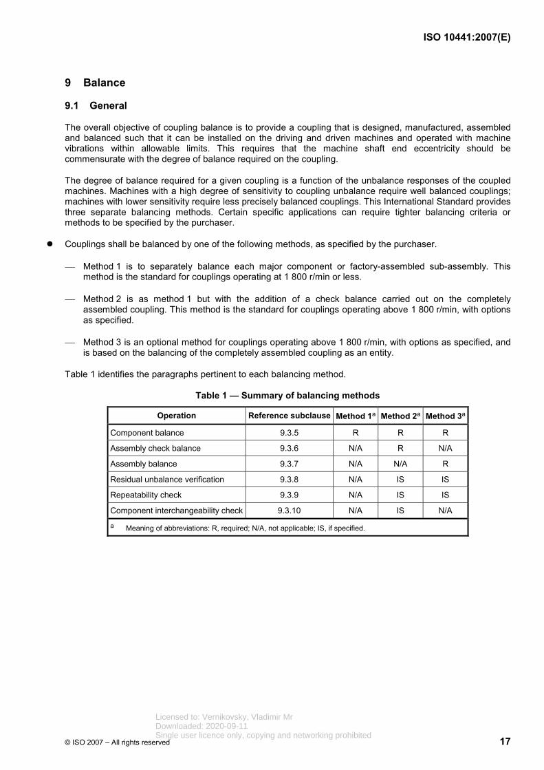
Table 1 identifies the paragraphs pertinent to each balancing method.
Table 1 — Summary of balancing methods
Operation Reference subclause Method 1a Method 2a Method 3a
Component balance 9.3.5 R R R
Assembly check balance 9.3.6 N/A R N/A
Assembly balance 9.3.7 N/A N/A R
Residual unbalance verification 9.3.8 N/A IS IS
Repeatability check 9.3.9 N/A IS IS
Component interchangeability check 9.3.10 N/A IS N/A
a Meaning of abbreviations: R, required; N/A, not applicable; IS, if specified.
Licensed to: Vernikovsky, Vladimir MrDownloaded: 2020-09-11Single user licence only, copying and networking prohibited

ISO 10441:2007(E)
18 © ISO 2007 – All rights reserved
9.2 Balancing methods
9.2.1 Method 1 — Component balance
All components shall be individually balanced to the limits stated and the technique described in 9.3.5.
This method is illustrated in Figure 2.
Figure 2 — Component balance procedure
Licensed to: Vernikovsky, Vladimir MrDownloaded: 2020-09-11Single user licence only, copying and networking prohibited
ISO 10441:2007(E)
© ISO 2007 – All rights reserved 19
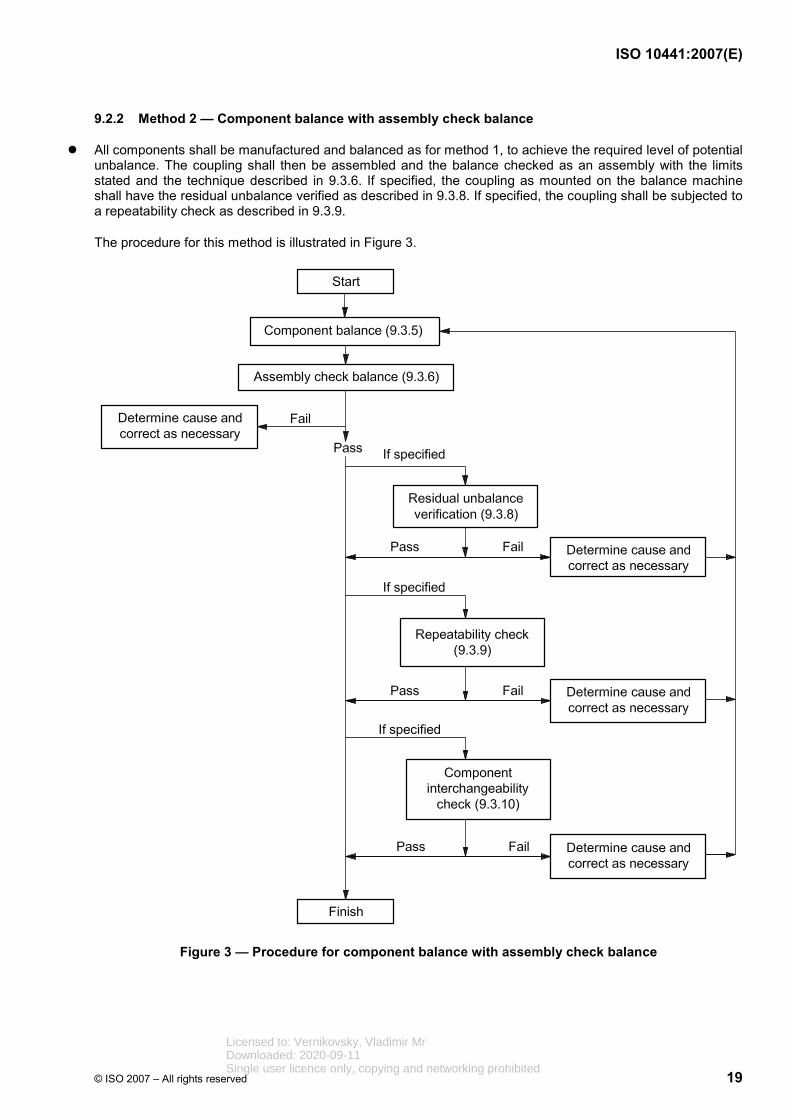
9.2.2 Method 2 — Component balance with assembly check balance
All components shall be manufactured and balanced as for method 1, to achieve the required level of potential unbalance. The coupling shall then be assembled and the balance checked as an assembly with the limits stated and the technique described in 9.3.6. If specified, the coupling as mounted on the balance machine shall have the residual unbalance verified as described in 9.3.8. If specified, the coupling shall be subjected to a repeatability check as described in 9.3.9.
The procedure for this method is illustrated in Figure 3.
Figure 3 — Procedure for component balance with assembly check balance
Licensed to: Vernikovsky, Vladimir MrDownloaded: 2020-09-11Single user licence only, copying and networking prohibited
ISO 10441:2007(E)
20 © ISO 2007 – All rights reserved
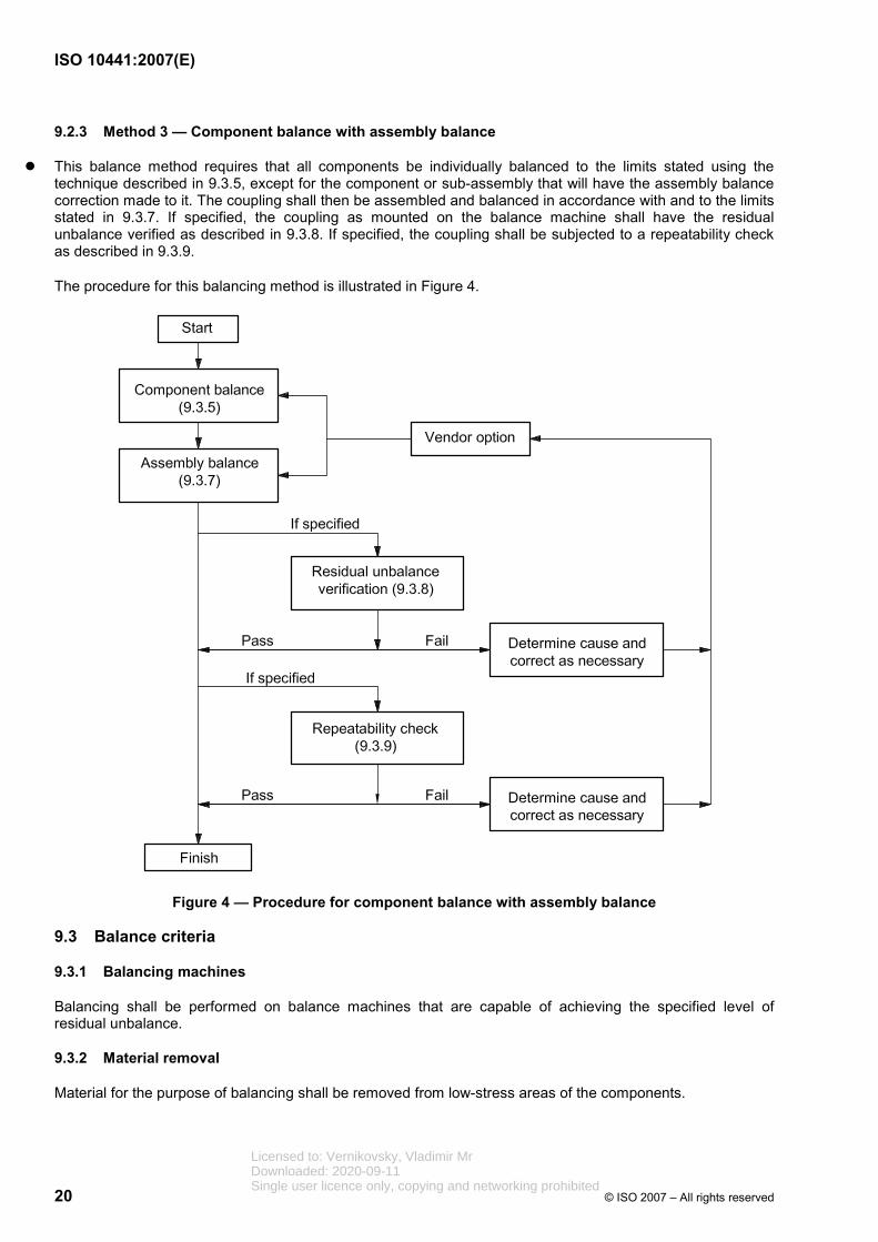
9.2.3 Method 3 — Component balance with assembly balance
This balance method requires that all components be individually balanced to the limits stated using the technique described in 9.3.5, except for the component or sub-assembly that will have the assembly balance correction made to it. The coupling shall then be assembled and balanced in accordance with and to the limits stated in 9.3.7. If specified, the coupling as mounted on the balance machine shall have the residual unbalance verified as described in 9.3.8. If specified, the coupling shall be subjected to a repeatability check as described in 9.3.9.
The procedure for this balancing method is illustrated in Figure 4.
Figure 4 — Procedure for component balance with assembly balance
9.3 Balance criteria
9.3.1 Balancing machines
Balancing shall be performed on balance machines that are capable of achieving the specified level of residual unbalance.
9.3.2 Material removal
Material for the purpose of balancing shall be removed from low-stress areas of the components.
Licensed to: Vernikovsky, Vladimir MrDownloaded: 2020-09-11Single user licence only, copying and networking prohibited

ISO 10441:2007(E)
© ISO 2007 – All rights reserved 21
9.3.3 Concentricity
Before balancing is started, the mounting surfaces of the component (the hub bore, sleeve pilot, and so forth) shall be aligned so that the component's geometric centre is concentric with the centre of rotation for balancing within 0,000 04 mm/mm (in/in) of mounting diameter or 6,4 µm (0,000 25 in), whichever is greater.
NOTE Determination of the geometric centre of rotation requires that the roundness of the component be identified. Once the roundness is identified, the geometric centre is then determined. This procedure differs from a conventional TIR reading in that a TIR reading does not directly compensate for roundness variations (for example, roundness variation due to jaw squeeze).
9.3.4 Fasteners
Each bolt, each nut and other similar components that require removal for normal field disassembly of the coupling, shall be mass balanced individually to a total tolerance of 0,05 % of the component's mass or 0,1 g (0,003 5 oz), whichever is greater.
9.3.5 Component balance
Couplings components shall be balanced by rotation. Each component, such as the hubs, sleeves, flexible elements, spacer, factory-assembled sub-assemblies, adapter plate(s), solo plate(s) and moment simulators, shall be balanced individually (except for the component or sub-assembly that is corrected as described in 9.3.7). All machining of components, except for keyway(s), shall be completed before balancing. The machining of keyway(s) prior to balancing is optional. Two-plane balancing is required for components or sub-assemblies with a length/diameter ratio greater than or equal to 1,0. Where the length/diameter ratio is less than 1,0, two-plane balancing is preferred but single-plane balancing is acceptable. Each component shall be balanced so that the level of residual unbalance, U, expressed in gram-millimetres (ounce-inches), for each balance plane does not exceed the greatest of the values determined by Equations (3) to (5):
2K mU
N⋅
= (3)
3U K m= ⋅ (4)
4U K= (5)
where
K2 is a constant, equal to 6 350 (4);
K3 is a constant, equal to 1,27 (0,000 8);
K4 is a constant, equal to 7,2 (0,01);
m is the mass, expressed in kilograms (pounds), of the component apportioned to one or the other of the balance planes so that the sum of the masses apportioned to the two planes equals the total mass of the component;
N is the maximum continuous operating speed, expressed in revolutions per minute.
Licensed to: Vernikovsky, Vladimir MrDownloaded: 2020-09-11Single user licence only, copying and networking prohibited

ISO 10441:2007(E)
22 © ISO 2007 – All rights reserved
9.3.6 Assembly check balance
Couplings balanced in accordance with 9.2.2 (component balance with assembly check balance) shall be assembled, the balance verified and the components shall be match marked. The residual unbalance, U, expressed in gram-millimetres (ounce-inches), for the randomly assembled coupling shall not exceed the greatest value determined by Equations (6) to (8):
5K mU
N⋅
= (6)
6U K m= ⋅ (7)
7U K= (8)
where
K5 is a constant, equal to 63 500 (40);
K6 is a constant, equal to 12,7 (0,008);
K7 is a constant, equal to 72 (0,1);
with the remaining variables the same as for Equations (3) to (5). Couplings that satisfy these criteria shall be match marked. Couplings that do not satisfy these criteria shall be inspected to determine the cause, which shall be corrected and the test shall be repeated. Trim balancing the assembly is not allowed.
9.3.7 Assembly balance
Couplings balanced in accordance with 9.2.3 (component balance with assembly balance) shall be assembly-balanced. For an assembly balance, coupling components or sub-assemblies shall be balanced in accordance with 9.3.5. The assembled coupling shall then be match-marked and two-plane balanced, with corrections being made only to the component or sub-assembly that was not previously balanced. The final residual unbalance of the assembled coupling in each of the two correction planes shall not exceed the greatest value determined by Equations (3) to (5).
NOTE Assembly balancing corrects for overall coupling unbalance caused by eccentricities of the pilot fits that are used to centre components during assembly. However, assembly balancing can prohibit the subsequent interchange of duplicate coupling components and can require that the entire coupling be maintained as a unit, except for the bolts and nuts.
9.3.8 Residual unbalance check
If specified, a residual unbalance check shall be performed on the assembled coupling. The residual unbalance check shall be performed after assembly balancing or assembly check balancing is complete and before the assembled coupling is removed from the balancing machine.
NOTE A procedure for a residual unbalance check is given in Annex I.
9.3.9 Repeatability check
If specified, the coupling shall be checked after the assembly balance or assembly check balance to ensure that the assembly balance can be repeated. The coupling shall be disassembled to the same extent required for normal field disassembly and remounted on the balance fixture or fixtures. The unbalance of the reassembled coupling shall then be measured on the balancing machine; the residual unbalance, U, expressed in gram-millimetres (ounce-inches), shall not exceed the greatest value determined by Equations (6) to (8).
Licensed to: Vernikovsky, Vladimir MrDownloaded: 2020-09-11Single user licence only, copying and networking prohibited

ISO 10441:2007(E)
© ISO 2007 – All rights reserved 23
9.3.10 Component interchangeability check
If specified and where interchangeable spare parts are to be supplied with the original coupling, a component interchangeability test shall be performed. After the coupling has been match-marked following an assembly check balance, it shall be disassembled to the same extent required for normal field disassembly and a major component, to be selected by the purchaser, shall be substituted and the coupling reassembled and remounted on the balance machine.
The unbalance of the coupling shall then be measured in the same manner and to the same criteria described in 9.3.9. The components shall be match-marked to identify proper positioning as applicable.
A major component shall normally be a rigid adapter, a flexible element sub-assembly, a spacer or a centre section containing flexible elements.
9.3.11 Balance mandrels
9.3.11.1 When balance mandrels are used, the mandrel shall have a surface roughness not exceeding 0,4 µm (16 microinches) arithmetic average (Ra) and shall exhibit no measurable eccentricity using an indicator graduated in 2,5 µm (0,000 1 in) increments.
Tapered spring mandrels shall not be used.
For components in which keyways have been machined prior to balance, inside crowned half keys or an equivalent compensating moment are required for proper balance, since mandrels are typically not keyed.
The mandrel mass should not exceed 25 % of the mass of the component or assembly being balanced.
9.3.11.2 The interference fit between a component and a mandrel shall not be less than 0,05 mm (0,002 in) or one quarter of the design fit between the component and the shaft, whichever is the lesser.
9.3.11.3 With the component mounted on the mandrel, the axial and radial phase related runout(s) (TIR) shall be recorded and shall not exceed 0,17 µm/mm (0,002 in/ft) of component diameter.
The location of this runout measurement should be at the same place as measured during disassembly and reassembly.
9.3.11.4 Components such as shaft end nuts, coupling hubs, etc., may be balanced on a vertical balancing machine.
9.4 Trim balance holes
If specified, threaded holes shall be provided in the coupling for trim balancing. The trim-balance holes should be capable of correcting for an unbalance, U, as given by Equation (9):
6U K m= ⋅ (9)
where
m is the mass, expressed in kilograms (pounds), of the component apportioned to one or the other of the balance planes so that the sum of the masses apportioned to the two planes equals the total mass of the component;
K6 is a constant, equal to 12,7 (0,008);
The number, size, depth and location of such holes shall be agreed upon by the purchaser and the vendor. The optimum hole location for keyed hubs is generally on the outboard faces of the hubs, midway between the inside and outside diameters of the hub barrel. The optimum location for keyless (hydraulically fitted) hubs is generally on the coupling flanges, between the bolt holes of the flange.
Licensed to: Vernikovsky, Vladimir MrDownloaded: 2020-09-11Single user licence only, copying and networking prohibited
ISO 10441:2007(E)
24 © ISO 2007 – All rights reserved
NOTE Because of eccentricity of the shaft end or incompletely filled keyways, trim balancing the rotor after the coupling hub has been mounted can be advisable. This practice normally precludes moving the hub to another rotor, unless balance is achieved by using balance holes as described in this subclause (9.4). When balance holes are used, the hub can always be returned to its original state of balance by removing the weights inserted into the holes.
10 Materials
10.1 Materials of construction shall be the manufacturer’s standard for the specified operating conditions, except as required or prohibited by the purchaser or by this International Standard.
10.2 The materials of construction of all major components shall be clearly stated in the vendor’s proposal. Materials shall be identified by reference to applicable International Standards, including the material grade. When no such designation is available, the vendor’s material specification, giving physical properties, chemical composition and test requirements, shall be included in the proposal.
10.3 The purchaser shall specify any corrosive agents present in the environment, including constituents that can cause stress corrosion cracking.
10.4 If a coupling operation in a corrosive environment is specified, either oil mist, a suitable coating or an inert gas purge can be required. The vendor shall advise the purchaser when material limitations demand such protection for the coupling.
10.5 Flexible elements shall be of corrosion-resistant material. If approved by the purchaser, flexible elements may be suitably coated to resist corrosion. The type of coating and its method of application shall be described by the vendor.
10.6 If specified, all other parts not covered by 10.5 shall be made from corrosion-resistant material or suitably coated.
10.7 All fasteners shall be of heat-treated steel, 510 MPa proof strength (for example, SAE J 429:1999, Grade 5), or stronger. If plated fasteners are used, they shall be treated properly to avoid cracking caused by hydrogen embrittlement.
11 Accessories
11.1 The purchaser shall specify who is to supply the necessary pumps, hoses and fittings, pressure gauges and other equipment required for the installation and removal of hydraulically fitted coupling hubs.
11.2 The vendor shall supply all special tools (that is tools that are not commercially available catalogue items) required for assembly and disassembly of the coupling, including jackscrews and other special devices required to separate closely piloted parts.
11.3 If specified by the purchaser, a two-piece stop-ring shall be provided to locate the advance (draw) of the hydraulically fitted coupling hub during installation. This stop-ring shall be designed to be clamped onto the shaft and shall be removable after the coupling is properly in place, whether installed in the shop or the field.
11.4 If specified by the purchaser, the vendor shall provide a puller for keyed coupling hubs.
11.5 If specified, the vendor shall supply a matched set of plug-and-ring gauges for each shaft-end taper.
These gauges shall meet the following requirements.
a) The hardness of the material of the gauge shall be greater than that of the shaft or coupling and not less than 45 HRC.
b) This plug-and-ring gauge set shall be verified with the machinery vendor's master plug and master ring gauges.
Licensed to: Vernikovsky, Vladimir MrDownloaded: 2020-09-11Single user licence only, copying and networking prohibited
ISO 10441:2007(E)
© ISO 2007 – All rights reserved 25
c) The plug-and-ring gauges shall meet the roundness, surface finish and contact requirements of this International Standard for coupling tapers.
d) The length of the ring-and-plug gauge shall at least be equal to the length of the coupling hub plus the advancement distance. The tools shall overlap the taper at each end.
e) Equipment drawings shall be reviewed for possible interference.
f) The gauges shall be marked “Gauge” in a non-critical location.
g) The storage preservation of these gauges shall satisfy the requirements of 12.5.4.
NOTE This gauge set is intended to become the master gauge set for the owner for use in inspection of both shaft and coupling taper.
11.6 If specified, the vendor shall supply a set of lapping tools in compliance with the following.
a) The lapping tools shall be softer than the shaft and hub.
b) Lapping tools shall overlap the taper at each end by a minimum of 12 mm.
c) Equipment drawings shall be reviewed for possible interference.
d) The lapping tools shall be marked “Lapping Tool” in a non-critical location.
e) The storage preservation of these tools shall satisfy the requirements of 12.5.4.
12 Manufacturing quality, inspection, testing and preparation for shipment
12.1 Manufacturing quality
12.1.1 The purchaser’s representative shall have access to the vendor’s quality programme for review.
12.1.2 Repair of defects by welding or plating in the torque-transmitting path shall not be undertaken without written authorization from the purchaser. Repair of other defects that do not affect the performance, reliability or safety of the coupling may be made at the discretion of the vendor.
12.1.3 Parts of duplicate couplings, except for meshing gear components, shall be manufactured within tolerances that permit interchangeability or replacement of parts in the field with minimal fitting; however, the assembly can require rebalancing after interchange of component parts.
12.1.4 The vendor shall remove all sharp edges of parts and components, with the exception of the threads.
12.1.5 Manufacturer’s markings, such as identification or match-marking, shall be on a low-stress area that does not affect the performance or integrity of the coupling.
12.2 Inspection and testing
12.2.1 The purchaser shall specify the extent of participation in the inspection and testing.
12.2.2 After advance notification to the vendor, the purchaser's representative shall have entry to all vendor and sub-vendor plants where manufacturing, testing or inspection of the equipment is in progress.
12.2.3 The vendor shall notify sub-vendors of the purchaser's inspection and testing requirements.
12.2.4 If shop inspection and testing have been specified, the purchaser and the vendor shall coordinate manufacturing hold points and inspector’s visits.
Licensed to: Vernikovsky, Vladimir MrDownloaded: 2020-09-11Single user licence only, copying and networking prohibited
ISO 10441:2007(E)
26 © ISO 2007 – All rights reserved
12.2.5 The purchaser shall specify the amount of advanced notification required for a witnessed or observed inspection or test.
For an observed inspection or test, the purchaser is notified of the timing of the inspection or test and the inspection or test is performed as scheduled if the purchaser or his representative is not present.
For a witnessed inspection or test, the purchaser is notified of the timing of the inspection or test and a hold is placed on the inspection or test until the purchaser or representative is in attendance.
12.2.6 Equipment, materials and utilities for the specified inspections and tests shall be provided by the vendor.
12.3 Inspection
12.3.1 It is the vendor’s responsibility to determine what tests and inspection procedures, in addition to any specified in this International Standard or by the purchaser, are necessary to ensure that materials and finished components are satisfactory for the service. Since the specification for the actual component being inspected depends on metallurgy, component configuration and method of manufacture, specific procedures and acceptance standards for the application should be covered by written documents, developed by the manufacturer for the specific application.
NOTE Standard tests and inspection techniques typically apply to a great variety of sizes, shapes, materials and widely varying examination requirements.
12.3.2 The vendor shall keep the following data available for at least five years for examination or reproduction by the purchaser or his representative upon request:
a) necessary certification of materials, such as mill test reports for all torque-transmitting components;
b) results of non-destructive tests;
c) results of documented tests and inspections, including fully identified records of all heat treatment and radiography;
d) balance data in accordance with Clause 9.
Periodic testing of the mechanical properties (such as ultimate tensile strength, yield strength, percentage elongation and percentage area reduction) of sample materials after heat treatment shall be performed at least twice annually and the results shall be documented.
12.3.3 The vendor shall keep data sufficient to enable the reproduction of a functionally equivalent coupling available for at least 20 years. These data should include a general arrangement drawing, parts list, material specification list and application data.
12.3.4 After final machining, all metallic torque-transmitting components, bolts and other major parts, with the exception of multiple-membrane diaphragms and discs, manufactured from cold rolled strip shall be inspected by wet magnetic-particle, fluorescent or dye penetrant methods. Indications of cracks or other injurious defects shall be the basis for rejection of the affected part. Certification of conformance is required.
12.3.5 All welds shall receive 100 % surface and subsurface inspection after final treatment. Magnetic-particle or dye-penetrant methods shall be used for surface inspection. Ultrasonic or radiographic methods shall be used for subsurface inspection. All weld-inspection procedures shall be agreed by the purchaser and the vendor.
12.4 Testing
12.4.1 If specified, couplings identified in 8.12.1 as having undamped response to external vibration shall be tested to verify the predicted natural frequency. The test technique shall be agreed by the purchaser and the vendor.
Licensed to: Vernikovsky, Vladimir MrDownloaded: 2020-09-11Single user licence only, copying and networking prohibited

ISO 10441:2007(E)
© ISO 2007 – All rights reserved 27
12.4.2 The purchaser's acceptance of shop tests does not constitute a waiver of the requirement to meet field-performance standards under specified operating conditions, and inspection by the purchaser does not relieve the vendor of his responsibilities.
12.5 Preparation for shipment
12.5.1 Before assembly and shipment, all surfaces of the coupling shall be cleaned and coated to prevent corrosion. Adequate instructions shall be provided for the removal of any temporary protective coating applied to the coupling components and any other preparation for operation. Any temporary protective coating that is applied to the bore of the hub shall have a tag indicating its existence and the recommended method of removal.
12.5.2 The purchaser shall specify the expected storage time and whether the storage location is to be indoors or outdoors.
12.5.3 The purchaser shall specify whether the packing to be provided is for domestic or export shipping.
12.5.4 Packing shall be adequate to prevent mechanical and corrosion damage during normal shipment and for the duration of the specified storage time.
12.5.5 Each coupling shall be properly identified by an item number and serial number stamped or etched on the coupling assembly (see 12.1.5). The container shall be marked with the information specified by the purchaser.
12.5.6 The vendor shall inscribe a serial number unique to the coupling on all of the coupling major separable parts. The vendor shall inscribe the recommended bolt torques on each flange. The purchaser may require the vendor to inscribe additional identifying markings, for example, markings to indicate equipment train or location of the coupling within the train.
13 Vendor data
13.1 General
13.1.1 The vendor shall provide the data detailed in 13.1.2. to 13.2. A detailed schedule for transmission of drawings, curves and data as agreed to at the time of the order, as well as the number and type of copies required by the purchaser, shall be supplied.
13.1.2 The data shall be identified on transmittal (cover) letters and in title blocks or pages with the following information:
a) purchaser/user's corporate name;
b) job/project number;
c) equipment name and item number;
d) purchase order number;
e) any other identification specified in the purchase order;
f) vendor's identifying shop-order number, serial number or other reference required to identify return correspondence completely.
13.1.3 If specified, the vendor shall attend the co-ordination meeting covering the connected equipment train and be prepared to discuss the following items:
a) purchase order, scope of supply and sub-vendor items;
b) data sheets; Licensed to: Vernikovsky, Vladimir MrDownloaded: 2020-09-11Single user licence only, copying and networking prohibited
ISO 10441:2007(E)
28 © ISO 2007 – All rights reserved
c) schedules for transmittal of drawings, production and testing;
d) inspection, expediting and testing;
e) review of applicable specifications and previously agreed exceptions to specifications;
f) design data for the coupling guard.
13.2 Proposals and contract data
13.2.1 General
The vendor's proposal shall include the information specified in items a) through g):
a) specific statement that the coupling and all its components are in strict accordance with this International Standard and the purchaser's specifications (if the system and its components are not in strict accordance, the vendor shall include a specific list of exceptions to the specifications that details and explains each deviation sufficiently to permit the purchaser to evaluate the offering);
b) copies of the purchaser's data sheets with complete vendor's information entered thereon;
c) typical cross-sectional drawings and literature;
d) when necessary, an itemized list of the special tools included in the offering;
e) any start-up, shut-down or operating restrictions required to protect the integrity of the coupling;
f) potential unbalance calculations, if specified; see 8.9.3;
g) if specified, a list of similar couplings installed and operating under analogous conditions.
13.2.2 Drawings
13.2.2.1 The purchaser shall state in the inquiry and in the order the number of prints and/or reproducible copies required and the timetable within which they are to be submitted by the vendor.
13.2.2.2 The purchaser shall promptly review the vendor's drawings when received; however, this review shall not constitute permission to deviate from any requirements in the order unless specifically agreed upon in writing. After the drawings have been reviewed, the vendor shall supply certified copies of the approved drawings in the quantity specified. Drawings shall be clearly legible and in accordance with ANSI Y14.2M.
13.2.2.3 The following information shall be provided on the coupling drawing(s). A copy of the finalized drawing shall be included with the shipment of the coupling. Typical drawings are not acceptable:
a) purchaser's order number (on every drawing);
b) purchaser's equipment item number (on every drawing);
c) make, type and size of the coupling;
d) mass of each part of the coupling and the mass of the entire assembled coupling;
e) mass and location of the centre of mass of each half coupling (the effective centre of mass of the half coupling is referenced from the equipment shaft end, with a positive location being beyond the shaft end and a negative location being within the shaft);
f) all principal overall outline, interface and other critical dimensions, including interface pilot diameters, gear pitch diameter, lengths, hub-to-hub and shaft-end spacing, hub bore details including keyways, hub-to-shaft interference fits, hub advances and axial float;
Licensed to: Vernikovsky, Vladimir MrDownloaded: 2020-09-11Single user licence only, copying and networking prohibited

ISO 10441:2007(E)
© ISO 2007 – All rights reserved 29
g) distance from centreline to centreline of the flexing elements;
h) if applicable, axial natural frequencies of flexible element couplings;
i) polar mass moment of inertia for each coupling half (including half of the spacer);
j) torsional spring constant, taking into consideration the entire length of the coupling between the points where the shafts enter the coupling hub on each end, which shall include a shaft penetration factor of 1/3 (or an alternative value based on the vendor's test data) and the expected accuracy or tolerance of these data. The calculation used to determine torsional spring constant shall conform to ANSI/AGMA 9004/9104 methods unless a more rigorous method, such as finite-element analysis or actual testing, is used;
NOTE The shaft-penetration factor is the portion of the shaft length within the confines of the coupling hub that is, for the purpose of calculating torsional rigidity, assumed to be free from restraint at the shaft-hub interface.
k) lateral natural frequency of the spacer, including assumptions that were used;
l) tightening and minimum prevailing torque (8.10.3 and 8.10.4) of all normally removable fasteners;
m) type and quantity of lubricant, and size and orientation of lubricant spray nozzles;
n) thread dimensions and trim-balancing hole dimensions;
o) materials of construction;
p) materials and outline dimensions of solo plate and/or moment simulator when supplied;
q) maximum permissible values of axial displacement and angular misalignment for continuous and transient operation;
r) description of match-mark locations and nomenclature;
s) continuous and peak torque rating and momentary torque limit;
t) for all hubs:
1) hub-to-shaft interference range,
2) hub draw-up range (for taper-bored fits),
3) torque capacity of hub-shaft interface (for keyless hubs only);
u) for flexible element couplings:
1) flexible-element lateral stiffness, that is, the ratio of the force to displacement while deflecting the coupling in a plane perpendicular to the coupling axis of rotation;
2) maximum axial force at maximum deflection or axial stiffness;
3) maximum bending moment or bending stiffness, that is, the force or bending moment required to angularly misalign a coupling to a specified angle while under torque load.
Licensed to: Vernikovsky, Vladimir MrDownloaded: 2020-09-11Single user licence only, copying and networking prohibited

ISO 10441:2007(E)
30 © ISO 2007 – All rights reserved
13.2.3 Data
13.2.3.1 The vendor shall provide completed data sheets.
13.2.3.2 The vendor shall make the following information available to the purchaser:
a) data required by mandate or purchaser decision as specified in 12.3.2 and 12.3.3;
b) certified balance records;
c) relationships as described in Clause A.5 as required.
13.2.3.3 The maximum enclosure temperature at the maximum continuous speed shall be calculated. It shall be agreed by the purchaser and the vendor who shall make these calculations. Enclosure data and ambient-temperature data at the coupling location shall be supplied by the purchaser.
13.2.3.4 The vendor shall supply a parts list for all equipment supplied. The list shall include pattern, stock or production drawing numbers and materials of construction. The list shall completely identify each part so that the purchaser can determine the interchangeability of the part with other couplings supplied by the same manufacturer. Standard purchased items shall be identified by the original vendor's name and part number. Materials shall be identified as specified in 10.2.
13.2.3.5 No more than five days after the actual shipment date, the vendor shall supply the required number of instruction manuals for the coupling provided by the vendor. The manuals shall include legible drawings of the specific equipment included (typical drawings are not acceptable), a parts list and completed data sheets. They shall include instructions covering installation, final tests and checks, start-up, shut-down, operating limits and operating and maintenance procedures. For flexible-element couplings, the manuals shall include pre-stretch or pre-compression values and instructions regarding the application of spacer shims. The manuals shall include instructions for the mounting and use of any devices, such as solo plates or moment simulators.
13.2.3.6 The vendor shall submit a supplementary list of spare parts other than those included in the original proposal. This supplementary list shall include recommended spare parts, cross-sectional or assembly-type drawings, parts numbers, materials, prices and delivery times. Parts numbers shall identify each part for purposes of interchangeability. Standard purchased items shall be identified by the original manufacturer's numbers.
Licensed to: Vernikovsky, Vladimir MrDownloaded: 2020-09-11Single user licence only, copying and networking prohibited
ISO 10441:2007(E)
© ISO 2007 – All rights reserved 31
Annex A (normative)
Torsional damping couplings and resilient couplings
A.1 General
A.1.1 The requirements of this annex apply to torsional damping and resilient couplings and replace the requirements in 8.1, except that the requirements of 8.1.4, 8.1.5 and 8.1.6 shall apply.
A.1.2 Torsional damping and resilient couplings are used in equipment trains in which potentially harmful torsional excitations occur during transient or continuous operation. Because of the unique, specialized nature of these couplings and the applications for which they are suited, they are treated in a tutorial manner in this annex.
A.1.3 The purchaser shall specify if it is necessary to use a resilient coupling.
A.2 Basic design
A.2.1 Torsional damping couplings and resilient couplings limit torque oscillations of coupled machinery by dissipating energy into one or more flexing elements. Generally, these couplings are applied to the lowest-speed shaft in an equipment train, and are, therefore, usually classified as low-speed. When some of the torsional natural frequencies of an equipment train fall below the running speed of the train (a normal occurrence), it is necessary that the train pass through these natural frequencies during start-up and again during normal or emergency shut-down.
A.2.2 Torsional damping couplings and resilient couplings are available with either metallic or elastomeric flexing elements. Some couplings with spring steel as the flexing element can be filled with oil to provide a high degree of viscous damping by oil displacement. Generally, couplings with elastomeric flexing elements exhibit lower torsional stiffness and higher damping capability than do those with metallic flexing elements. Torsional damping couplings and resilient couplings are usually used on the low-speed side of a drive-train and are often used in combination with another type of coupling (gear, disc, or diaphragm). This combination may be used for several reasons, such as to accommodate axial movement and to reduce the mass (usually on the shaft-end of the driven equipment).
If a resilient coupling is used in conjunction with a metallic flexible element, (disc or diaphragm), or gear or quill-shaft coupling, those parts shall be in accordance with the appropriate section of this International Standard.
A.2.3 Unless otherwise agreed, initial sizing shall be accomplished by multiplying the normal steady-state torque by 3,0 and comparing this to the peak capacity of the coupling. These couplings are usually sized based on transient/peak torques that are determined by doing a detailed system analysis. The peak capacity of the elastomeric flexible element of the coupling shall be greater than the calculated transient/peak torque by 1,15. The momentary torque limit of the elastomeric flexible element of the coupling shall be greater than the very infrequent high-transient torque. All other components (bolts, hubs, spacers) shall comply with the requirements of 7.2 and 7.3.
A.2.4 The coupling damping shall be sufficient to reduce torsional vibration stresses in the machinery train to a safe level.
A.2.5 The purchaser shall specify any material constraints regarding flexible elements.
A.2.6 The purchaser shall specify minimum requirements for torsional damping and the allowable range of torsional stiffness for the coupling.
Licensed to: Vernikovsky, Vladimir MrDownloaded: 2020-09-11Single user licence only, copying and networking prohibited

ISO 10441:2007(E)
32 © ISO 2007 – All rights reserved
A.2.7 The purchaser shall specify any restrictions regarding the use of elastomers in shear.
A.2.8 Couplings that use elastomers in compression shall be designed to accommodate the resultant Poisson expansion in the axial direction.
A.2.9 Elastomeric elements shall be designed to dissipate the required vibrational energy without overheating.
A.2.10 The purchaser shall specify whether the coupling is a single- or double-engagement type, based on misalignment requirements.
A.2.11 The purchaser shall specify whether the coupling is a spacer or non-spacer type, taking the maintenance requirements of the coupled equipment into consideration and shall specify the length of spacer, if required.
A.2.12 Fits shall be to the manufacturer’s standard to meet the balance and interface connection requirements. The requirements of 8.9 do not apply.
A.2.13 The surface finish of the components of the couplings may be to the manufacturer’s standard provided that the coupling meets the design requirements and balance requirements of this International Standard.
A.2.14 The lateral natural frequency (Nc) of that portion of the coupling between and including the resilient elements (or combination of resilient and flexing elements, if appropriate), assuming infinitely stiff supports, shall be at least two times the highest specified operating speed for the uniform-tube-equation methodology as specified in ANSI/AGMA 9004 or ANSI/AGMA 9104 or at least 1,5 times the highest specified operating speed, using a more rigorous analysis based on actual geometry (i.e. finite-element analysis). The purchaser and vendor shall agree who shall perform these calculations and the assumptions used.
NOTE The actual lateral frequency of the coupling is affected by the stiffness of any flange adapter(s) and shaft extension(s). The calculation to determine this actual number is complex. This subclause (A.2.14) establishes a default value to use when little else is known, such as during the proposal stages of a design.
A.2.15 Temperature, oscillatory torque and its frequency shall be included in the rating of the coupling as stated in 7.1.
A.3 Balance
A.3.1 Unless otherwise specified, the resilient coupling, including any part of a metallic flexible-element coupling or a gear coupling, shall be balanced by balancing the individual components to limits set in 9.3.5. Separate elastomeric, flexible elements shall be mass-balanced to a tolerance of 0,1 g (0,003 5 oz).
A.3.2 If specified, the coupling shall be check-balanced and/or assembly-balanced. Assembly-balance check limits and balance limits shall be agreed by the purchaser and the vendor.
A.4 Materials of construction
A.4.1 The materials of construction, including elastomers, shall be agreed by the purchaser and the vendor. The purchaser shall specify pertinent operating conditions (including environmental conditions), such as temperature, corrosiveness of the atmosphere and air-borne abrasives.
A.4.2 Hubs, sleeves and spacers shall preferably be forged. Welded spacers are acceptable. Ductile iron construction is permissible but grey cast-iron is not acceptable.
A.4.3 The requirements of Clause 10, except that of 10.5, shall apply.
Licensed to: Vernikovsky, Vladimir MrDownloaded: 2020-09-11Single user licence only, copying and networking prohibited

ISO 10441:2007(E)
© ISO 2007 – All rights reserved 33
A.5 Vendor's data
A.5.1 The vendor shall state the relationship between the coupling continuous torque, speed, the coupling maximum continuous angular misalignment and the coupling maximum continuous axial displacement as a function of temperature, oscillatory torque and its frequency, if the rated maximum values of each cannot be accepted simultaneously.
A.5.2 For couplings with non-linear torsional stiffness, the vendor shall supply a curve or tabulation of deflection versus torque and instantaneous values of equivalent viscous damping. Where applicable, the effects of temperature, speed and frequency of vibration shall be taken into consideration.
A.5.3 If specified, the vendor shall state the life expectancy of the elastomeric elements when they are operating at the specified conditions (including environmental conditions).
Licensed to: Vernikovsky, Vladimir MrDownloaded: 2020-09-11Single user licence only, copying and networking prohibited
ISO 10441:2007(E)
34 © ISO 2007 – All rights reserved
Annex B (normative)
Gear couplings
B.1 General
B.1.1 The requirements of this annex apply to gear couplings and replace the requirements of 8.1.
B.1.2 Gear couplings are not normally recommended for new applications. Possible exceptions are
⎯ when large axial displacements are not practical to accommodate with metallic flexible-element couplings (disc or diaphragms),
⎯ where the diameter of the coupling is restricted and a gear coupling, because of its high power density, is the only type of coupling that fits into the system.
B.1.3 The purchaser shall specify if it is necessary to use a gear coupling.
B.2 Coupling selection
B.2.1 The coupling shall be selected based on the equipment loading and shall be capable of transmitting the maximum steady-state torques, continuous cyclic torques and the maximum transient torques under all conditions of angular misalignment, axial displacement, speed and temperature, simultaneously, to which it will be subjected in service.
B.2.2 Unless otherwise specified, the gear coupling shall be rated using a service factor of 1,75 based on the steady-state selection torque and Equation (2).
NOTE This factor of 1,75 has been found by experience to be satisfactory for gear couplings in typical turbomachinery applications. It is different from the recommended service factor of 1,5 for metallic flexible-element couplings. The metallic flexible-element couplings are treated more precisely by having a coupling flexible-element factor of safety, for use in addition to the equipment service factor.
B.2.3 Where appropriate a reduced service factor may be applied as outlined in 6.8.
B.3 Coupling design
B.3.1 The purchaser shall specify the maximum axial displacements that the coupling is expected to experience, expressed as the amount and direction of the movement of the shaft ends toward or away from each other as the coupled machines go through their start-up, normal operation and shut-down cycle. These dimensions shall be given from the position of the machine under non-operating, ambient conditions. Unless otherwise specified, the total axial displacement the coupling shall be capable of accepting shall be not less than 6 mm (1/4 in). The purchaser shall specify limited-end-float design if required by the equipment train.
A limited-end-float coupling is one in which the axial displacement is positively prevented from exceeding a specific value.
B.3.2 All gear couplings shall be the double-engagement type.
B.3.3 The purchaser shall specify whether the coupling shall have the external teeth on the hub (constituting a flex-hub coupling) or on the spacer (sometimes referred to as a marine-type coupling).
B.3.4 The coupling design shall ensure that all components are positively centred. The gear meshes shall be centred at the crown diameter of the external teeth and at the root diameter of the internal teeth. The crown
Licensed to: Vernikovsky, Vladimir MrDownloaded: 2020-09-11Single user licence only, copying and networking prohibited

ISO 10441:2007(E)
© ISO 2007 – All rights reserved 35
clearance of the tooth diameter shall be the maximum clearance possible that maintains the specified balance. On flex-hub couplings, the crown clearance shall allow for radial stretch resulting from the hub-to-shaft interference fit.
The root diameter is the diameter of the root circle of the internal teeth.
B.3.5 For hubs in couplings to operate at speeds greater than 1 800 r/min, pilot fits at gear-coupling teeth shall be concentric to the bore within 0,000 08 mm/mm TIR (0,001 in/ft TIR) of diameter or 0,013 mm (0,000 5 in) TIR, whichever is greater. For couplings operating at 1 800 r/min or less, fits are required to meet only the balance tolerance.
B.3.6 For sleeves in couplings to operate at speeds greater than 1 800 r/min, pilot fits at gear coupling teeth shall be concentric to the rabbet within 0,000 08 mm/mm TIR (0,001 in/ft TIR) of diameter or 0,025 mm (0,001 in) TIR, whichever is greater. Pilot fits shall be round within 0,000 16 mm/mm TIR (0,002 in/ft TIR) of diameter or 0,038 mm (0,001 5 in) TIR, whichever is greater. For couplings operating at 1 800 r/min or less, fits are required to meet only the balance tolerance.
B.3.7 The involute tooth form shall be used. External teeth shall be relieved or chamfered at the tips and edges to provide the required misalignment capability and torque capacity. The amount of backlash in the mesh, that is the gear tooth circumferential clearance, shall be held to the minimum value commensurate with the vendor’s stated maximum permissible misalignment.
B.3.8 The hardness of the gear teeth shall be at least 45 on the Rockwell C (Rc) scale. The hardness of the teeth with the greater face width (generally the sleeve teeth) shall be greater than or equal to the hardness of the mating teeth.
B.3.9 If specified, couplings shall be designed for batch lubrication. Otherwise, couplings shall be designed for continuous lubrication.
B.3.10 To minimize the accumulation of foreign material and excessive temperature rise, continuously lubricated couplings shall be of flooded mesh design and designed to minimize the accumulation of sludge. Each gear mesh shall be fed separately with filtered oil. The purchaser shall specify the viscosity, pressure, temperature and degree of filtration of the oil supply (to be provided by others). The vendor shall state the rate of oil flow that the coupling requires.
B.4 Vendor data
The following data shall be supplied in addition to that required by Clause 13:
a) lube-oil and cooling-system requirements for the coupling, when applicable,
b) axial force at normal operating torque at the assumed coefficient of friction,
c) bending moment at normal operating torque and rated misalignment at the assumed coefficient of friction.
Licensed to: Vernikovsky, Vladimir MrDownloaded: 2020-09-11Single user licence only, copying and networking prohibited
ISO 10441:2007(E)
36 © ISO 2007 – All rights reserved
Annex C (normative)
Quill-shaft couplings
C.1 General
C.1.1 The requirements of this annex apply to quill-shaft couplings and replace the requirements of 8.1.
C.1.2 The purchaser shall specify whether a quill-shaft coupling shall be supplied.
C.1.3 Quill-shaft couplings shall not be used between two shafts that are both constrained by thrust bearings. However, quill-shaft couplings may be combined with one of the other types of coupling to overcome the inherent inability to accommodate axial displacement.
C.2 Coupling selection and design
C.2.1 The coupling shall be selected based on the equipment loading and shall be capable of transmitting the maximum steady-state torques, continuous cyclic torques and the maximum transient torques under all conditions of angular misalignment, speed and temperature, simultaneously, to which it will be subjected in service.
C.2.2 The purchaser shall specify the maximum misalignments the coupling is expected to experience during start-up, normal operation and shut-down of the coupled machines, normally expressed as parallel (or lateral) offset and/or angular misalignment between the coupled shafts. These values shall allow for all the known effects on the machines from thermal, pressure and dynamic forces.
C.2.3 The lateral natural frequency (Nc) of the coupling, assuming infinitely stiff supports, shall be at least two times the highest specified operating speed for the uniform tube equation methodology as specified in ANSI/AGMA 9004 or ANSI/AGMA 9014 or at least 1,5 times the highest specified operating speed using a more rigorous analysis based on actual geometry (i.e. finite-element analysis). The purchaser and vendor shall agree who shall perform these calculations and the assumptions used.
NOTE The actual lateral frequency of the coupling is affected by the stiffness of any flange adapter(s) and shaft extension(s). The calculation to achieve this actual number is complex. This subclause (C.2.3) establishes a default value to use when little else is known, such as in the proposal stages of a design.
C.2.4 Unless otherwise specified, the quill-shaft coupling shall be rated using a service factor of 1,5 based on the steady-state torque. See 6.6.
C.2.5 Unless otherwise specified, quill shafts shall have integral end flanges.
Licensed to: Vernikovsky, Vladimir MrDownloaded: 2020-09-11Single user licence only, copying and networking prohibited
ISO 10441:2007(E)
© ISO 2007 – All rights reserved 37
Annex D (informative)
Factors for metallic element couplings
D.1 Service factors
A service factor is applied to the normal operating torque of the connected equipment, in order to select a coupling. This service factor allows for various modes of off-design operation of the equipment, such as torsional oscillations, unequal load sharing, changes in the conditions of fluid or compressed gas, blade fouling or driver output at maximum conditions. It is a factor to account for unknown or little-understood changes in load that a coupling can experience. It is a factor applied to the equipment loading.
Once this service factor is selected, this service factor multiplied by the normal torque is then used to select the coupling based on catalogue published torque ratings for continuous operation.
In accordance with 6.10, 6.13, and 6.14, the torque capacity of a coupling-to-shaft hydraulically fitted, keyless juncture is required to be greater than the normal operating torque including a service factor of 1,75 applied and not less than 115 % of the maximum transient torque. The shaft-end diameter has a great influence on this torque capacity.
D.2 Factors of safety
The safety of the coupling design is covered by the coupling factors of safety.
The methods used by coupling manufacturers to rate a coupling for continuous operation are described in 7.1. This establishes the minimum fatigue factor of safety and the methods for applying them to recognized material properties (i.e. fatigue strength, yield strength and ultimate tensile strength). This methodology standardizes the basis for published continuous ratings, so that different manufacturers' ratings can be compared on a more equivalent basis.
In 7.2, the minimum factor of safety with respect to the material yield strength for transient and momentary coupling limits is described.
This International Standard does not address the details of the design, such as equations or analysis used to derive the stresses or how these stresses are combined. This information is often considered proprietary and, as such, is not normally made available to the purchaser except by special agreement. As to how these stresses are derived and combined, a certain level of confidence is required in each coupling manufacturer based on experience with their product.
D.3 Typical fatigue diagram
Figure D.1 is a typical fatigue diagram incorporating a modified Goodman line and a constant-life curve.
The fatigue factor of safety can be defined as the length of the line from the origin to either the modified Goodman line or the constant life curve, divided by the length of the line from the origin to the combined stresses point, i.e., the line segment 0 - 4 divided by the line segment 0 - 3 in Figure D.1.
The fatigue factor of safety is then compared to the minimum requirement outlined in 7.1 to determine whether it is acceptable.
NOTE This factor of safety is not related to a defined equipment operating point; it is for the combination of maximum ratings published in a catalogue or stated on the coupling contract drawing. The actual factor of safety for an equipment operating point is typically much greater.
Licensed to: Vernikovsky, Vladimir MrDownloaded: 2020-09-11Single user licence only, copying and networking prohibited
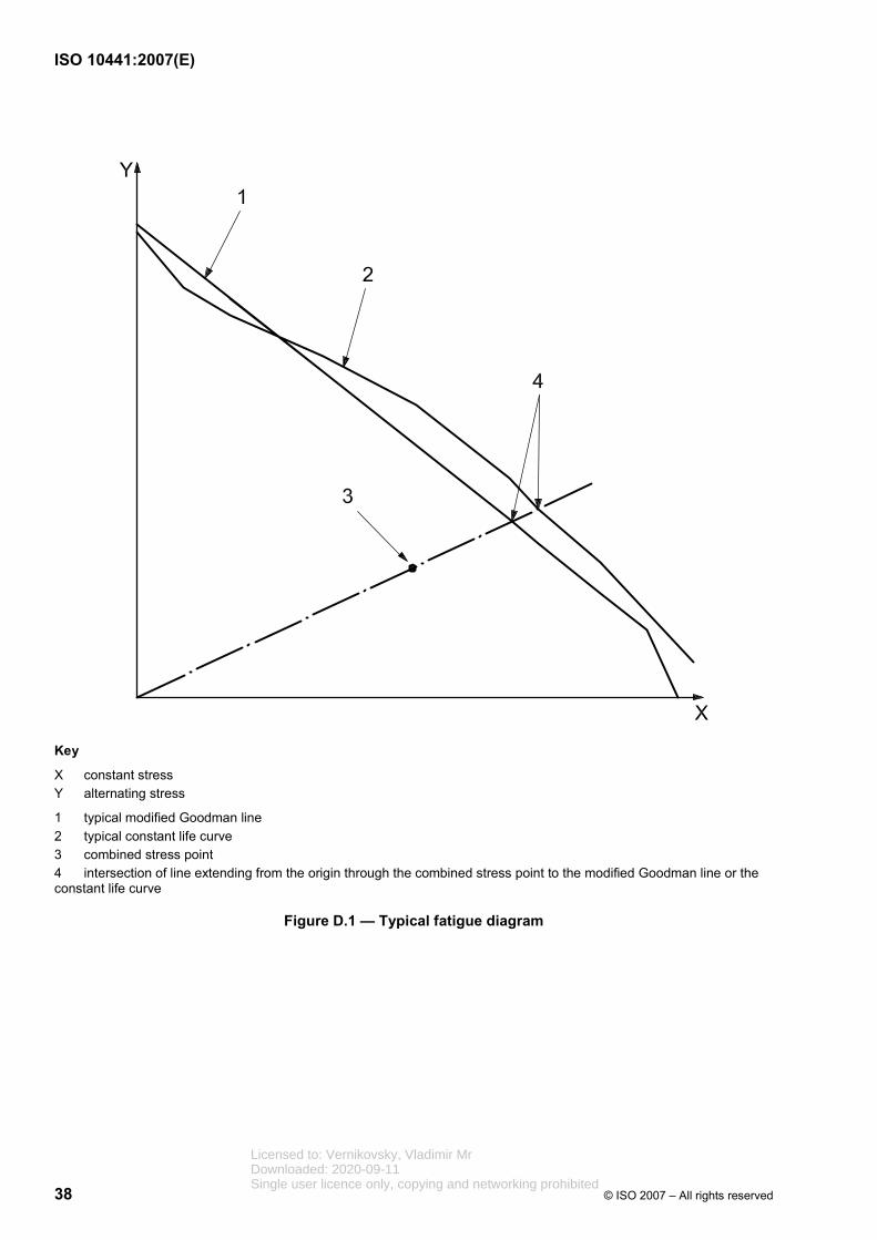
ISO 10441:2007(E)
38 © ISO 2007 – All rights reserved
Key
X constant stress Y alternating stress
1 typical modified Goodman line 2 typical constant life curve 3 combined stress point 4 intersection of line extending from the origin through the combined stress point to the modified Goodman line or the constant life curve
Figure D.1 — Typical fatigue diagram
Licensed to: Vernikovsky, Vladimir MrDownloaded: 2020-09-11Single user licence only, copying and networking prohibited
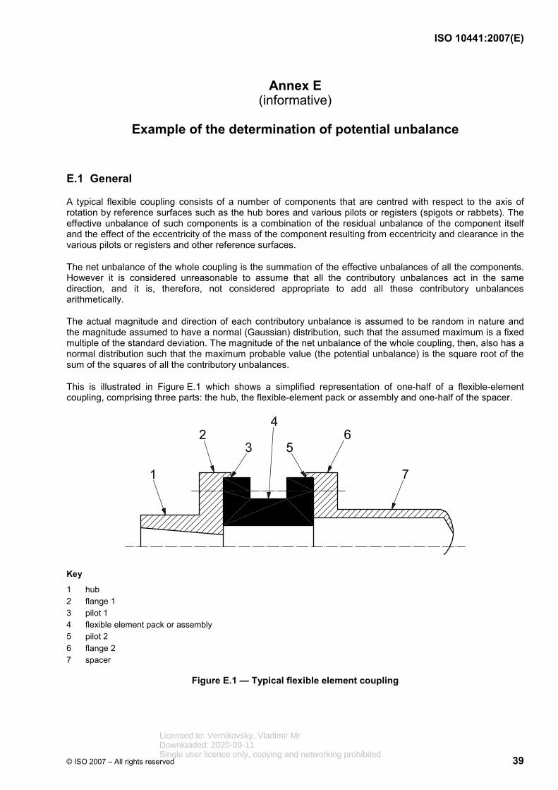
ISO 10441:2007(E)
© ISO 2007 – All rights reserved 39
Annex E (informative)
Example of the determination of potential unbalance
E.1 General
A typical flexible coupling consists of a number of components that are centred with respect to the axis of rotation by reference surfaces such as the hub bores and various pilots or registers (spigots or rabbets). The effective unbalance of such components is a combination of the residual unbalance of the component itself and the effect of the eccentricity of the mass of the component resulting from eccentricity and clearance in the various pilots or registers and other reference surfaces.
The net unbalance of the whole coupling is the summation of the effective unbalances of all the components. However it is considered unreasonable to assume that all the contributory unbalances act in the same direction, and it is, therefore, not considered appropriate to add all these contributory unbalances arithmetically.
The actual magnitude and direction of each contributory unbalance is assumed to be random in nature and the magnitude assumed to have a normal (Gaussian) distribution, such that the assumed maximum is a fixed multiple of the standard deviation. The magnitude of the net unbalance of the whole coupling, then, also has a normal distribution such that the maximum probable value (the potential unbalance) is the square root of the sum of the squares of all the contributory unbalances.
This is illustrated in Figure E.1 which shows a simplified representation of one-half of a flexible-element coupling, comprising three parts: the hub, the flexible-element pack or assembly and one-half of the spacer.
Key
1 hub 2 flange 1 3 pilot 1 4 flexible element pack or assembly 5 pilot 2 6 flange 2 7 spacer
Figure E.1 — Typical flexible element coupling
Licensed to: Vernikovsky, Vladimir MrDownloaded: 2020-09-11Single user licence only, copying and networking prohibited

ISO 10441:2007(E)
40 © ISO 2007 – All rights reserved
E.2 Main characteristics
Running speed: 5 000 r/min;
Masses: hub (mh): 10 kg;
flexible-element assembly (mf): 12 kg;
half-spacer (msp): 15 kg.
E.3 Balancing
The coupling is component-balanced as follows:
a) hub, balanced on a mandrel to ISO 1940-1:2003, grade 2.5:
1) maximum mandrel residual unbalance: 7 g·mm,
2) maximum eccentricity of mounting surface, eh: 10 µm,
3) maximum eccentricity of pilot 1 to bore, ei: 0 µm;
b) flexible-element assembly, locked and supported on a fixture at pilot 1 and balanced to ISO 1940-1:2003, grade 2.5:
1) maximum fixture residual unbalance: 7 g·mm,
2) maximum eccentricity of register (pilot 1) on fixture, ef: 5 µm,
3) diametral clearance at register on fixture: 0,
4) diametral clearance at hub connection (pilot 1): 0,
5) maximum eccentricity, e2, of pilot 1 to pilot 2: 10 µm;
c) spacer, balanced by rolling on outer surface of tube to ISO 1940-1:2003, grade 2.5:
1) maximum eccentricity, esp, of register to flexible assembly with respect to rolling surfaces: 5 µm,
2) clearance, csp, at register spacer-to-flexible element assembly (pilot 2): 10 µm;
d) bolting (both flanges): 12 (N) bolts on 200 mm pitch circle diameter (Db):
1) maximum diametral bolt-hole clearance, cb: 100 µm;
2) maximum variation in bolt-hole radius, Vr,bh: 100 µm;
3) mass, mb of each bolt: 50 g; max. variation (heaviest to lightest), Vm,b: 0,1 g.
4) mass, mnut, of each nut: 10 g; max. variation (heaviest to lightest): Vm,nut: 0,1 g.
NOTE ISO 1940-1:2003, grade 2.5, at 5 000⋅r/min represents a maximum unbalance of 5 g⋅mm/kg.
Licensed to: Vernikovsky, Vladimir MrDownloaded: 2020-09-11Single user licence only, copying and networking prohibited

ISO 10441:2007(E)
© ISO 2007 – All rights reserved 41
E.4 Contributory unbalance
The various contributory unbalances are listed in Table E.1.
Table E.1 — Contributory unbalance
Element Calculation Unbalance U
g·mm
U2 (g·mm)2
Residual unbalance of hub mh × 5 50 2 500
Unbalance of hub due to mandrel eccentricity
mh × eh 100 10 000
Unbalance due to residual unbalance of hub mandrel
— 7 49
Residual unbalance of flexible-element assembly
mf × 5 60 3 600
Unbalance of flex-element assembly due to fixture register eccentricity
mf × ef 60 3 600
Unbalance due to residual unbalance of flexible-element assembly fixture
— 7 49
Residual unbalance of half-spacer msp × 5 75 5 625
Unbalance of half-spacer due to eccentricity of register
msp × esp 75 5 625
Unbalance of flex-element assembly plus half-spacer plus flange 2 fasteners due to pilot 1 eccentricity
[mf + msp + N(mb + mnut)] × e1 277,2 76 839,84
Unbalance of half-spacer due to eccentricity of pilot 1 to pilot 2
msp × e2 150 22 500
Unbalance of half-spacer due to clearance at pilot 2
msp × csp/2 75 5 625
Flange 1 unbalance due to bolt and nut radial displacement ( ) b
b nut r,bh+ /1 000 2cN m m V N+ × ⎛ ⎞⎜ ⎟
⎝ ⎠31,2 973,44
Flange 2 unbalance due to nut and bolt radial displacement ( ) b
b nut r,bh+ /1 000 2cN m m V N+ × ⎛ ⎞⎜ ⎟
⎝ ⎠31,2 973,44
Flange 1 unbalance due to variation in mass of bolts b
m,b 2D NV × ×π
15,6 243,36
Flange 1 unbalance due to variation in mass of nuts b
m,b 2D NV × ×π
15,6 243,36
Flange 2 unbalance due to variation in mass of bolts b
m,b 2D NV × ×π
15,6 243,36
Flange 2 unbalance due to variation in mass of nuts b
m,b 2D NV × ×π
15,6 243,36
Total — 1 061,00 138 933,16
Licensed to: Vernikovsky, Vladimir MrDownloaded: 2020-09-11Single user licence only, copying and networking prohibited
ISO 10441:2007(E)
42 © ISO 2007 – All rights reserved
E.5 Potential unbalance
The potential unbalance, U, equals the square root of the sum of the squares per half coupling:
U = 138 933,16 = 373 g⋅mm.
Total mass of the half coupling is 37,36 kg for hub, flex element assembly, half the hardware and half of the spacer.
The mass displacement, mdis, of the principal inertia axis is then calculated as follows:
mdis = 373 × 106 /(1 000 × 1 000 × 37,36) = 9,98 µm (272 microinches)
In accordance with 8.9.3, a coupling operating at 5 000 r/min should not exceed ANSI/AGMA 9000-C90, Class 11, that is, a mass centre displacement of 13 µm (500 microinches). Therefore, the example coupling satisfies the requirement.
NOTE For the derivation of the equations used to calculate the various contributory unbalances and further information on the concept of potential unbalance, the user of this International Standard is referred to ANSI/AGMA 9000.
Licensed to: Vernikovsky, Vladimir MrDownloaded: 2020-09-11Single user licence only, copying and networking prohibited
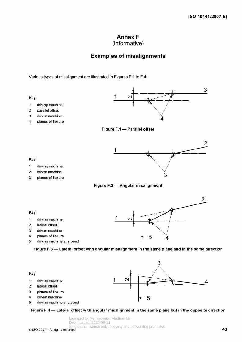
ISO 10441:2007(E)
© ISO 2007 – All rights reserved 43
Annex F (informative)
Examples of misalignments
Various types of misalignment are illustrated in Figures F.1 to F.4.
Key
1 driving machine 2 parallel offset 3 driven machine 4 planes of flexure
Figure F.1 — Parallel offset
Key
1 driving machine 2 driven machine 3 planes of flexure
Figure F.2 — Angular misalignment
Key
1 driving machine 2 lateral offset 3 driven machine 4 planes of flexure 5 driving machine shaft-end
Figure F.3 — Lateral offset with angular misalignment in the same plane and in the same direction
Key
1 driving machine 2 lateral offset 3 planes of flexure 4 driven machine 5 driving machine shaft-end
Figure F.4 — Lateral offset with angular misalignment in the same plane but in the opposite direction
Licensed to: Vernikovsky, Vladimir MrDownloaded: 2020-09-11Single user licence only, copying and networking prohibited
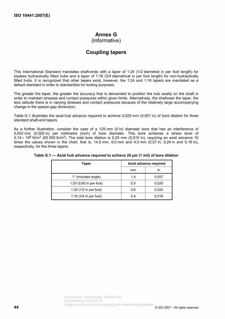
ISO 10441:2007(E)
44 © ISO 2007 – All rights reserved
Annex G (informative)
Coupling tapers
This International Standard mandates shaft-ends with a taper of 1:24 (1/2 diametral in per foot length) for keyless hydraulically fitted hubs and a taper of 1:16 (3/4 diametrical in per foot length) for non-hydraulically fitted hubs. It is recognized that other tapers exist, however, the 1:24 and 1:16 tapers are mandated as a default standard in order to standardize for tooling purposes.
The greater the taper, the greater the accuracy that is demanded to position the hub axially on the shaft in order to maintain stresses and contact pressures within given limits. Alternatively, the shallower the taper, the less latitude there is in varying stresses and contact pressures because of the relatively large accompanying change in the spacer-gap dimension.
Table G.1 illustrates the axial-hub advance required to achieve 0,025 mm (0,001 in) of bore dilation for three standard shaft-end tapers.
As a further illustration, consider the case of a 125 mm (5 in) diameter bore that has an interference of 0,002 mm (0,002 in) per millimetre (inch) of bore diameter. This bore achieves a stress level of 4,14 × 10⁸ N/m2 (60 000 lb/in2). The total bore dilation is 0,25 mm (0,010 in), requiring an axial advance 10 times the values shown in the chart, that is, 14,5 mm, 6,0 mm and 4,0 mm (0,57 in, 0,24 in and 0,16 in), respectively, for the three tapers.
Table G.1 — Axial hub advance required to achieve 25 µm (1 mil) of bore dilation
Axial advance required Taper
mm in
1° (included angle) 1,4 0,057
1:20 (0,60 in per foot) 0,5 0,020
1:24 (1/2 in per foot) 0,6 0,024
1:16 (3/4 in per foot) 0,4 0,016
Licensed to: Vernikovsky, Vladimir MrDownloaded: 2020-09-11Single user licence only, copying and networking prohibited

ISO 10441:2007(E)
© ISO 2007 – All rights reserved 45
Annex H (normative)
Coupling guards
H.1 Scope
This annex covers the minimum requirements for guards used with special-purpose couplings. This information is added as a convenience to the owner or the contractor in specifying the total requirements for the driving and driven equipment system. Coupling guards are usually supplied by the machinery vendor rather than by the manufacturer of the coupling. Therefore, this annex does not pertain to the requirements for special-purpose couplings, as such.
H.2 General requirements for all guards
H.2.1 The purchaser shall designate who coordinates and who is responsible for the supply of all coupling guards in the equipment train.
H.2.2 The purchaser shall specify the types of guards that are required.
H.2.3 Each coupling shall have a coupling guard that sufficiently encloses the coupling and shafts to prevent any personnel from accessing the rotating parts during operation of the equipment train.
H.2.4 The guard shall be readily removable for inspection and maintenance of the coupling without disturbance of the coupled machines.
H.2.5 The guard shall be constructed to be rigid enough to withstand a 90 kg (200 lb) static load with a deflection of not more than 0,000 5 times the unsupported length of the guard.
H.2.6 The guard shall comply with the requirements of any local codes or regulations, for example OHSA Standard 1910.219-O, or EN 953.
H.2.7 If specified, the guard shall be oil-tight.
H.2.8 The guard shall contain anti-swirl baffles as required to minimize the effects of windage.
H.2.9 If specified, the guard shall be fabricated from spark-resistant material, such as aluminium, aluminium alloys, copper or copper-based alloys. A description of the materials of construction shall be submitted to the purchaser for approval.
H.2.10 The guard shall include features to minimize the heat generated by the rotating components and have, as a minimum, a 25 mm (1 in) radial clearance between the maximum coupling outside diameter and the guard inside diameter. The vendor supplying the guard shall confirm the expected surface temperature of the guard. It is recommended that the maximum guard temperature should not exceed 70 °C (160 °F). If the guard temperature exceeds this value consideration should be given to providing personnel protection from contact with the guard.
H.3 Base-mounted guards
H.3.1 Guards that are fastened to the equipment foundation or baseplate shall be removable in one piece.
H.3.2 Base-mounted guards shall preferably be fabricated from a solid metal sheet or plate with no openings. Guards that are fabricated from expanded metal or perforated plate are acceptable, provided that the size of the opening is small enough to prevent entry by objects that are 10 mm (3/8 in) or larger in diameter. Guards of woven wire are unacceptable.
Licensed to: Vernikovsky, Vladimir MrDownloaded: 2020-09-11Single user licence only, copying and networking prohibited

ISO 10441:2007(E)
46 © ISO 2007 – All rights reserved
H.4 Fully enclosed guards
H.4.1 Fully enclosed guards shall preferably be cylindrical in shape and shall be axially split with provision at each end for connection to the coupled equipment. If a slip joint is required at one end of the guard, the joint shall be provided with two O-rings. Alternatively, expansion may be accommodated by using a flexible bellows or the equivalent.
H.4.2 If adapting flanges are required to mate the guard to the associated components of the equipment train, the vendor designated in H.2.1 shall be responsible for their design and supply.
H.4.3 Fully enclosed guards shall be oil-tight and provided with vent and drain connections. As a minimum, these vent and drain connections shall be DN 25 (NPS1) and, if specified, flanged.
H.4.4 If the guard is designed to cool the enclosure using air flow, there should be at least two baffled inlet air vents, located in a plane different from that of the exit air port(s). Note that the oil drain may also serve as the air exit port. This is so that air circulates throughout the enclosure. The air-exit area should be at least twice the combined inlet-vent area.
NOTE A technical paper by Calistrat and Munyon[4] provides guidelines for the design and evaluation of coupling guards for temperature conditions.
H.4.5 A threaded filter breather shall be supplied for attachment to the vent(s) unless otherwise specified. In applications where the vent is piped or included as part of the vent system for the equipment train, this connection shall be flanged, in which case the breather is not required. Flanged drain connections, as a minimum, shall be DN 25 (NPS1) and capable of handling the oil carryover from the coupled equipment. It is recommended that the drain connection be tangential to the enclosure outside diameter and conform to the coupling direction of rotation.
H.4.6 A baffle should also be installed along the enclosure over the exit port to prevent the oil from rotating around more than one revolution before exiting. In guards 900 mm (36 in) or longer, it can be necessary to have two drains, one at each end, in different planes than the inlet vents if air cooling is used.
H.4.7 If specified, the guard shall be fitted with a connection for purging with dry air or an inert gas.
NOTE This is necessary when unusually corrosive conditions exist.
H.4.8 If specified, the contract guard shall be used when the contract coupling is factory tested with the driver and driven equipment.
H.5 Guards for continuously lubricated couplings
H.5.1 In addition to the requirements listed in Clause H.4, the following shall apply to coupling guards for continuously lubricated couplings.
H.5.2 Each oil-spray nozzle shall be positively fastened to the guard in the proper orientation and the mounting shall ensure that this orientation is easily re-established if removal of the nozzle is required for maintenance. Friction clamping of nozzles or tubing in unacceptable.
H.5.3 Guards shall be designed to remain oil-tight for at least five years of operation. A flanged oil drain connection, DN 25 (NPS1) or larger in size, shall be provided for each guard.
H.5.4 If specified, a transparent window shall be provided to permit safe inspection of each oil spray while the coupling is in service.
H.6 Guards for instrumented couplings
In addition to requirements noted above, guards containing instrumentation such as torque meters shall be designed so that the internal temperature does not exceed the maximum allowable temperature of the enclosed instrumentation.
Licensed to: Vernikovsky, Vladimir MrDownloaded: 2020-09-11Single user licence only, copying and networking prohibited
ISO 10441:2007(E)
© ISO 2007 – All rights reserved 47
Annex I (informative)
Procedure for residual unbalance check
I.1 General
This annex describes a procedure that may be used to determine the residual unbalance in complete couplings. Although some balancing machines can be set up to read out the exact amount of unbalance, the calibration can be in error. The only sure method of determining the residual unbalance is to test the coupling with a known amount of unbalance.
I.2 Residual unbalance
Residual unbalance is the amount of unbalance remaining after balancing. Unless otherwise specified, residual unbalance shall be expressed in g·mm (oz·in).
I.3 Maximum allowable residual unbalance
I.3.1 The maximum allowable residual unbalance, U, per plane, shall be calculated in accordance with 9.3.6 or 9.3.7 as appropriate.
I.3.2 The mass apportioned to each balance plane shall be determined. It should not simply be assumed that the mass is equally divided between the two balance planes unless the coupling is truly symmetrical.
I.4 Residual unbalance check
I.4.1 General
I.4.1.1 When the balancing machine readings indicate that the coupling has been balanced within the specified tolerance, a residual-unbalance check shall be performed before the coupling is removed from the balancing machine.
I.4.1.2 To check the residual unbalance, a known trial mass is attached to the coupling in one balance plane, sequentially in six equally spaced angular positions (60° apart), each at the same radius. For each trial mass position, the balancing machine readings are tabulated and plotted on the polar graph using the procedure specified in I.4.2.
I.4.2 Procedure
I.4.2.1 Select a trial mass and radius that are equivalent to between one and two times the maximum allowable residual unbalance [e.g., if U is 488,4 g·mm (0,68 oz·in), the trial mass should cause 488,4 g⋅mm to 976,8 g⋅mm (0,68 oz⋅in to 1,36 oz⋅in) of unbalance]. This trial mass and radius shall be sufficient so that the resulting plot, as described in I.4.2.5, encompasses the origin of the polar plot.
I.4.2.2 Starting at a convenient reference position in one balance plane (i.e. last heavy spot), mark off the specified six radial positions (60° increments) around the coupling. Add the trial mass near the last known heavy spot for that plane. Verify that the balance machine is responding and is within the range and graph selected for taking the residual unbalance check.
I.4.2.3 Verify that the balancing machine is responding reasonably (i.e. no faulty sensors or displays). For example, if the trial mass is added to the last known heavy spot, the first meter reading should be at least twice as much as the last reading taken before the trial mass was added. A low or no meter reading generally indicates that the coupling is not balanced to the correct tolerance, the balancing machine is not sufficiently
Licensed to: Vernikovsky, Vladimir MrDownloaded: 2020-09-11Single user licence only, copying and networking prohibited
ISO 10441:2007(E)
48 © ISO 2007 – All rights reserved
sensitive or that a balancing machine fault exists (for example, a faulty pickup). Proceed, if this initial test is satisfactory.
I.4.2.4 Remove the trial mass and rotate it to the next trial position (that is, 60°, 120°, 180°, 240°, 300° and 360° from the initial trial mass position). Repeat the initial position as a check for repeatability and record the results on the residual-unbalance worksheet (see Tables I.1 and I.2). All verification shall be performed using only one sensitivity range on the balance machine.
I.4.2.5 Plot the balancing machine amplitude readout in each measurement plane versus the angular location of the trial mass (not the balancing-machine phase angle) on the polar chart and calculate the amount of residual unbalance (see the residual-unbalance worksheet in Tables I.1 and I.2).
The maximum reading occurs when the trial mass is placed at the coupling’s remaining heavy spot; the minimum reading occurs when the trial mass is placed opposite the coupling’s heavy spot (light spot). The plotted readings should form an approximate circle enclosing the origin of the polar chart. The balance-machine angular location readout should approximate the location of the trial weight. The maximum deviation (highest reading) is the heavy spot (represents the plane of the residual unbalance).
I.4.2.6 Repeat the steps described in I.4.2.1 through I.4.2.5 for each balance plane. If the specified maximum allowable residual unbalance has been exceeded in any balance plane, the coupling shall be balanced more precisely and checked again. If a balance correction is made in any balance plane, then the residual-unbalance check shall be repeated in all balance planes.
I.4.2.7 Where the coupling is balanced by mounting it on a mandrel and the mass of the mandrel is greater than 20 % of the mass of the coupling, the residual unbalance of the mandrel alone should be determined first. The residual unbalance of the coupling is then determined by deducting the residual unbalance of the mandrel vectorially from the residual unbalance of the mandrel plus coupling.
Licensed to: Vernikovsky, Vladimir MrDownloaded: 2020-09-11Single user licence only, copying and networking prohibited
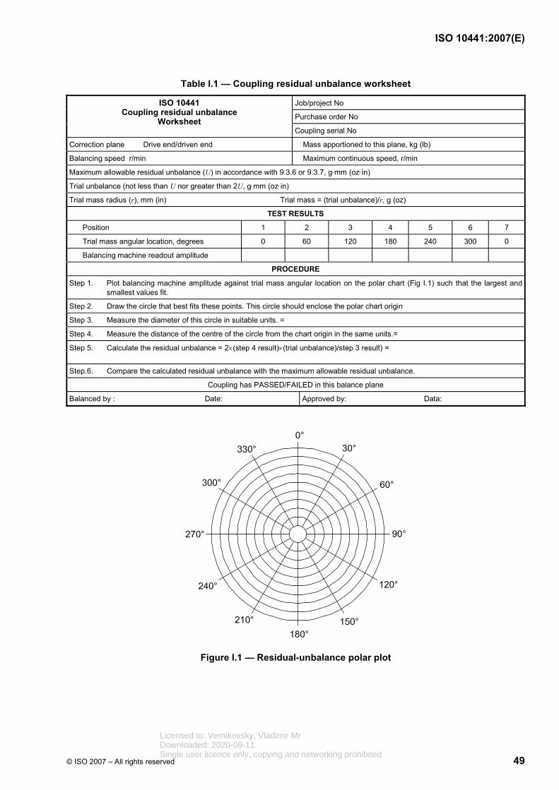
ISO 10441:2007(E)
© ISO 2007 – All rights reserved 49
Table I.1 — Coupling residual unbalance worksheet
Job/project No
Purchase order No
ISO 10441 Coupling residual unbalance
Worksheet Coupling serial No
Correction plane Drive end/driven end Mass apportioned to this plane, kg (lb)
Balancing speed r/min Maximum continuous speed, r/min
Maximum allowable residual unbalance (U) in accordance with 9.3.6 or 9.3.7, g⋅mm (oz⋅in)
Trial unbalance (not less than U nor greater than 2U, g⋅mm (oz⋅in)
Trial mass radius (r), mm (in) Trial mass = (trial unbalance)/r, g (oz)
TEST RESULTS
Position 1 2 3 4 5 6 7
Trial mass angular location, degrees 0 60 120 180 240 300 0
Balancing machine readout amplitude
PROCEDURE
Step 1. Plot balancing machine amplitude against trial mass angular location on the polar chart (Fig I.1) such that the largest and smallest values fit.
Step 2. Draw the circle that best fits these points. This circle should enclose the polar chart origin
Step 3. Measure the diameter of this circle in suitable units. =
Step 4. Measure the distance of the centre of the circle from the chart origin in the same units.=
Step 5. Calculate the residual unbalance = 2×(step 4 result)×(trial unbalance)/step 3 result) =
Step.6. Compare the calculated residual unbalance with the maximum allowable residual unbalance.
Coupling has PASSED/FAILED in this balance plane
Balanced by : Date: Approved by: Data:
Figure I.1 — Residual-unbalance polar plot
Licensed to: Vernikovsky, Vladimir MrDownloaded: 2020-09-11Single user licence only, copying and networking prohibited
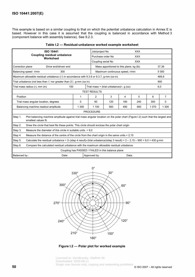
ISO 10441:2007(E)
50 © ISO 2007 – All rights reserved
This example is based on a similar coupling to that on which the potential unbalance calculation in Annex E is based. However in this case it is assumed that the coupling is balanced in accordance with Method 3 (component balance with assembly balance). See 9.2.3.
Table I.2 — Residual-unbalance worked example worksheet
Job/project No XXX
Purchase order No XXX
ISO 10441 Coupling residual unbalance
Worksheet Coupling serial No XXX
Correction plane Drive end/driven end Mass apportioned to this plane, kg (lb) 37,36
Balancing speed r/min 300 Maximum continuous speed, r/min 5 000
Maximum allowable residual unbalance (U) in accordance with 9.3.6 or 9.3.7, g⋅mm (oz⋅in) 469,9
Trial unbalance (not less than U nor greater than 2U, g⋅mm (oz⋅in) 900
Trial mass radius (r), mm (in) 150 Trial mass = (trial unbalance)/r, g (oz) 6,0
TEST RESULTS
Position 1 2 3 4 5 6 7
Trial mass angular location, degrees 0 60 120 180 240 300 0
Balancing machine readout amplitude 1 300 1 100 560 490 560 1 070 1 300
PROCEDURE
Step 1. Plot balancing machine amplitude against trial mass angular location on the polar chart (Figure I.2) such that the largest and smallest values fit.
Step 2. Draw the circle that best fits these points. This circle should enclose the polar chart origin
Step 3. Measure the diameter of this circle in suitable units. = 9,0
Step 4. Measure the distance of the centre of the circle from the chart origin in the same units.= 2,15
Step 5. Calculate the residual unbalance = 2×(step 4 result)×(trial unbalance)/step 3 result) = 2 × 2,15 × 900 = 9,0 = 430 g⋅mm
Step.6. Compare the calculated residual unbalance with the maximum allowable residual unbalance.
Coupling has PASSED / FAILED in this balance plane
Balanced by : Date: Approved by: Data:
Figure I.2 — Polar plot for worked example
Licensed to: Vernikovsky, Vladimir MrDownloaded: 2020-09-11Single user licence only, copying and networking prohibited
ISO 10441:2007(E)
© ISO 2007 – All rights reserved 51
Annex J (informative)
Coupling datasheets
J.1 Datasheets in SI units (2 pages)
Licensed to: Vernikovsky, Vladimir MrDownloaded: 2020-09-11Single user licence only, copying and networking prohibited
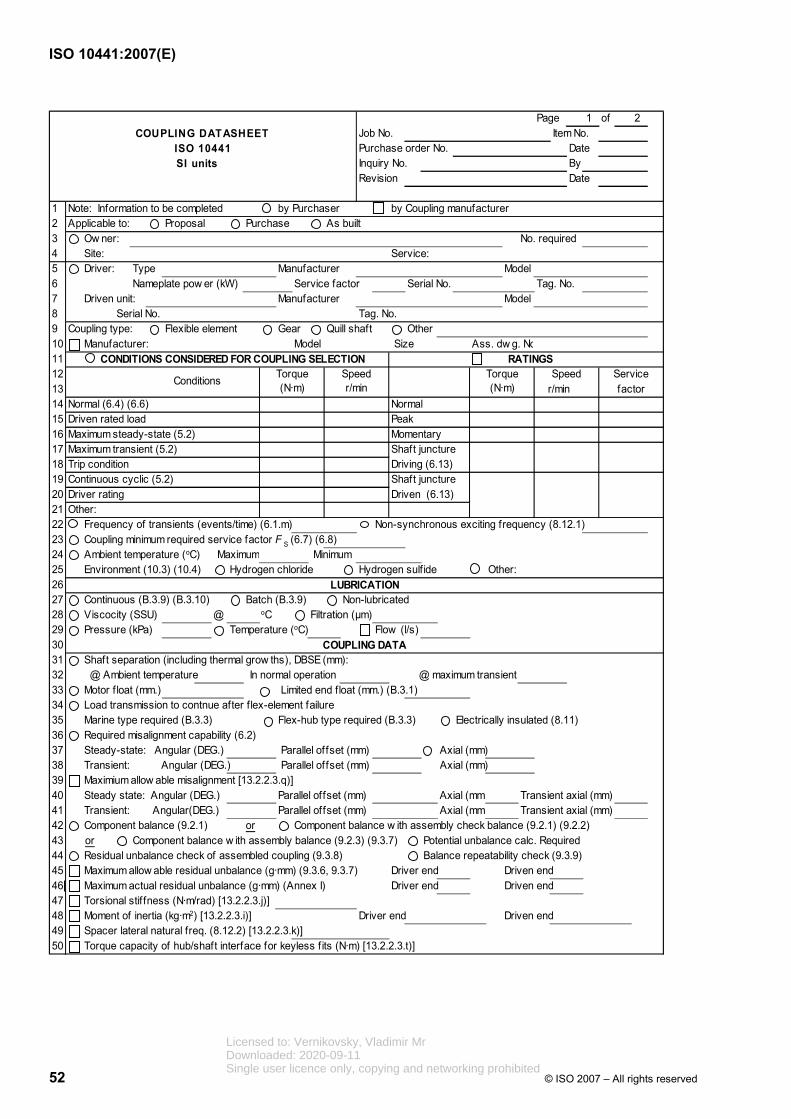
ISO 10441:2007(E)
52 © ISO 2007 – All rights reserved
Page 1 of 2COUPLING DATASHEET Job No. Item No.
ISO 10441 Purchase order No. Date SI units Inquiry No. By
Revision Date
1 Note: Information to be completed by Purchaser by Coupling manufacturer2 Applicable to: Proposal Purchase As built3 Ow ner: No. required4 Site: Service:5 Driver: Type Manufacturer Model6 Nameplate pow er (kW) Service factor Serial No. Tag. No.7 Driven unit: Manufacturer Model8 Serial No. Tag. No.9 Coupling type: Flexible element Gear Quill shaft Other10 Manufacturer: Model Size Ass. dw g. No11 CONDITIONS CONSIDERED FOR COUPLING SELECTION RATINGS12 Torque Speed Torque Speed Service13 r/min factor14 Normal (6.4) (6.6) Normal15 Driven rated load Peak16 Maximum steady-state (5.2) Momentary17 Maximum transient (5.2) Shaft juncture 18 Trip condition Driving (6.13)19 Continuous cyclic (5.2) Shaft juncture20 Driver rating Driven (6.13) 21 Other:22 Frequency of transients (events/time) (6.1.m) Non-synchronous exciting frequency (8.12.1)23 Coupling minimum required service factor F S (6.7) (6.8)24 Ambient temperature (oC) Maximum Minimum25 Environment (10.3) (10.4) Hydrogen chloride Hydrogen sulfide Other:26 LUBRICATION27 Continuous (B.3.9) (B.3.10) Batch (B.3.9) Non-lubricated28 Viscocity (SSU) @ oC Filtration (µm)29 Pressure (kPa) Temperature (oC) Flow (l/s)30 COUPLING DATA31 Shaft separation (including thermal grow ths), DBSE (mm):32 @ Ambient temperature In normal operation @ maximum transient33 Motor f loat (mm.) Limited end float (mm.) (B.3.1)34 Load transmission to contnue after flex-element failure 35 Marine type required (B.3.3) Flex-hub type required (B.3.3) Electrically insulated (8.11)36 Required misalignment capability (6.2)37 Steady-state: Angular (DEG.) Parallel offset (mm) Axial (mm)38 Transient: Angular (DEG.) Parallel offset (mm) Axial (mm)39 Maximium allow able misalignment [13.2.2.3.q)]40 Steady state: Angular (DEG.) Parallel offset (mm) Axial (mm. Transient axial (mm)41 Transient: Angular(DEG.) Parallel offset (mm) Axial (mm) Transient axial (mm)42 Component balance (9.2.1) or Component balance w ith assembly check balance (9.2.1) (9.2.2)43 or Component balance w ith assembly balance (9.2.3) (9.3.7) Potential unbalance calc. Required44 Residual unbalance check of assembled coupling (9.3.8) Balance repeatability check (9.3.9)45 Maximum allow able residual unbalance (g·mm) (9.3.6, 9.3.7) Driver end Driven end46 Maximum actual residual unbalance (g·mm) (Annex I) Driver end Driven end47 Torsional stif fness (N·m/rad) [13.2.2.3.j)]48 Moment of inertia (kg·m2) [13.2.2.3.i)] Driver end Driven end49 Spacer lateral natural freq. (8.12.2) [13.2.2.3.k)]50 Torque capacity of hub/shaft interface for keyless f its (N·m) [13.2.2.3.t)]
Conditions (N·m) r/min (N·m)
Licensed to: Vernikovsky, Vladimir MrDownloaded: 2020-09-11Single user licence only, copying and networking prohibited
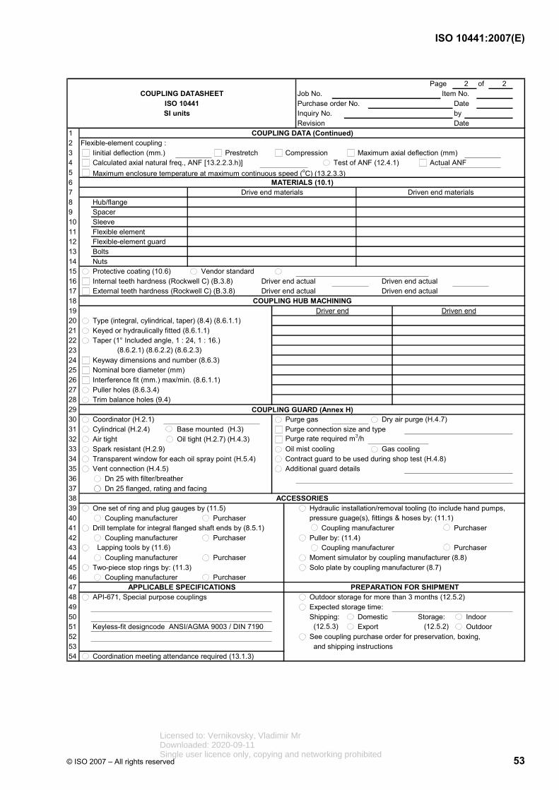
ISO 10441:2007(E)
© ISO 2007 – All rights reserved 53
Page 2 of 2COUPLING DATASHEET Job No. Item No.
ISO 10441 Purchase order No. Date SI units Inquiry No. by
Revision Date1 COUPLING DATA (Continued)2 Flexible-element coupling :3 Iinitial deflection (mm.) Prestretch Compression Maximum axial deflection (mm)4 Calculated axial natural freq., ANF [13.2.2.3.h)] Test of ANF (12.4.1) Actual ANF5 Maximum enclosure temperature at maximum continuous speed (oC) (13.2.3.3)6 MATERIALS (10.1)7 Drive end materials Driven end materials8 Hub/flange9 Spacer10 Sleeve11 Flexible element12 Flexible-element guard13 Bolts14 Nuts15 Protective coating (10.6) Vendor standard16 Internal teeth hardness (Rockwell C) (B.3.8) Driver end actual Driven end actual17 External teeth hardness (Rockwell C) (B.3.8) Driver end actual Driven end actual18 COUPLING HUB MACHINING19 Driver end Driven end20 Type (integral, cylindrical, taper) (8.4) (8.6.1.1)21 Keyed or hydraulically fitted (8.6.1.1)22 Taper (1° Included angle, 1 : 24, 1 : 16.)23 (8.6.2.1) (8.6.2.2) (8.6.2.3)24 Keyway dimensions and number (8.6.3)25 Nominal bore diameter (mm)26 Interference fit (mm.) max/min. (8.6.1.1)27 Puller holes (8.6.3.4)28 Trim balance holes (9.4)29 COUPLING GUARD (Annex H)30 Coordinator (H.2.1) Purge gas Dry air purge (H.4.7)31 Cylindrical (H.2.4) Base mounted (H.3) Purge connection size and type32 Air tight Oil tight (H.2.7) (H.4.3) Purge rate required m3/h33 Spark resistant (H.2.9) Oil mist cooling Gas cooling34 Transparent window for each oil spray point (H.5.4) Contract guard to be used during shop test (H.4.8)35 Vent connection (H.4.5) Additional guard details36 Dn 25 with filter/breather37 Dn 25 flanged, rating and facing38 ACCESSORIES39 One set of ring and plug gauges by (11.5) Hydraulic installation/removal tooling (to include hand pumps,40 Coupling manufacturer Purchaser pressure guage(s), fittings & hoses by: (11.1)41 Drill template for integral flanged shaft ends by (8.5.1) Coupling manufacturer Purchaser42 Coupling manufacturer Purchaser Puller by: (11.4)43 Coupling manufacturer Purchaser44 Coupling manufacturer Purchaser Moment simulator by coupling manufacturer (8.8)45 Two-piece stop rings by: (11.3) Solo plate by coupling manufacturer (8.7) 46 Coupling manufacturer Purchaser47 APPLICABLE SPECIFICATIONS PREPARATION FOR SHIPMENT48 API-671, Special purpose couplings Outdoor storage for more than 3 months (12.5.2)49 Expected storage time:50 Shipping: Domestic Storage: Indoor51 Keyless-fit designcode ANSI/AGMA 9003 / DIN 7190 (12.5.3) Export (12.5.2) Outdoor52 See coupling purchase order for preservation, boxing,53 and shipping instructions54 Coordination meeting attendance required (13.1.3)
Lapping tools by (11.6)
Licensed to: Vernikovsky, Vladimir MrDownloaded: 2020-09-11Single user licence only, copying and networking prohibited
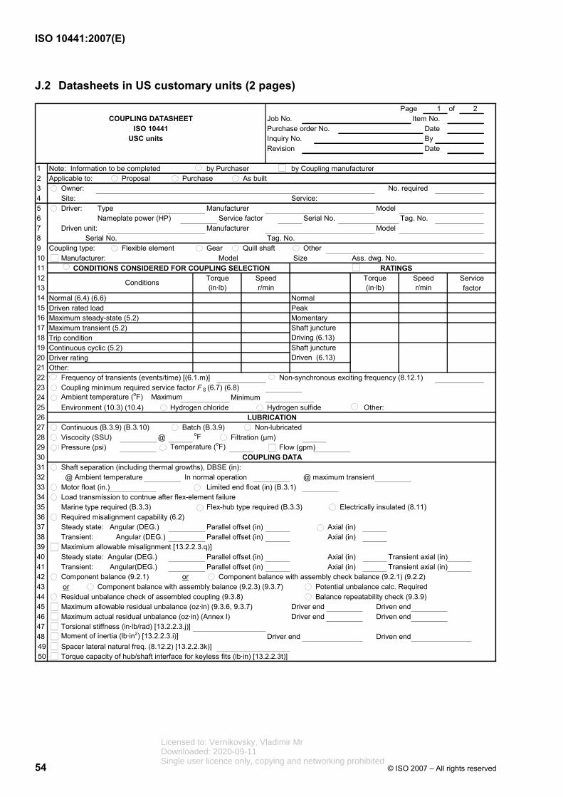
ISO 10441:2007(E)
54 © ISO 2007 – All rights reserved
J.2 Datasheets in US customary units (2 pages)
Page 1 of 2COUPLING DATASHEET Job No. Item No.
ISO 10441 Purchase order No. Date USC units Inquiry No. By
Revision Date
1 Note: Information to be completed by Purchaser by Coupling manufacturer2 Applicable to: Proposal Purchase As built3 Owner: No. required4 Site: Service:5 Driver: Type Manufacturer Model6 Nameplate power (HP) Service factor Serial No. Tag. No.7 Driven unit: Manufacturer Model8 Serial No. Tag. No.9 Coupling type: Flexible element Gear Quill shaft Other10 Manufacturer: Model Size Ass. dwg. No.11 CONDITIONS CONSIDERED FOR COUPLING SELECTION RATINGS12 Torque Speed Torque Speed Service13 factor14 Normal (6.4) (6.6) Normal15 Driven rated load Peak16 Maximum steady-state (5.2) Momentary17 Maximum transient (5.2) Shaft juncture 18 Trip condition Driving (6.13)19 Continuous cyclic (5.2) Shaft juncture20 Driver rating Driven (6.13) 21 Other:22 Frequency of transients (events/time) [(6.1.m)] Non-synchronous exciting frequency (8.12.1)23 Coupling minimum required service factor F S (6.7) (6.8)24 Ambient temperature (oF) Maximum Minimum25 Environment (10.3) (10.4) Hydrogen chloride Hydrogen sulfide Other:26 LUBRICATION27 Continuous (B.3.9) (B.3.10) Batch (B.3.9) Non-lubricated28 Viscocity (SSU) @ oF Filtration (µm)29 Pressure (psi) Temperature (oF) Flow (gpm)30 COUPLING DATA31 Shaft separation (including thermal growths), DBSE (in):32 @ Ambient temperature In normal operation @ maximum transient33 Motor float (in.) Limited end float (in) (B.3.1)34 Load transmission to contnue after flex-element failure 35 Marine type required (B.3.3) Flex-hub type required (B.3.3) Electrically insulated (8.11)36 Required misalignment capability (6.2)37 Steady state: Angular (DEG.) Parallel offset (in) Axial (in)38 Transient: Angular (DEG.) Parallel offset (in) Axial (in)39 Maximium allowable misalignment [13.2.2.3.q)]40 Steady state: Angular (DEG.) Parallel offset (in) Axial (in) Transient axial (in)41 Transient: Angular(DEG.) Parallel offset (in) Axial (in) Transient axial (in)42 Component balance (9.2.1) or Component balance with assembly check balance (9.2.1) (9.2.2)43 or Component balance with assembly balance (9.2.3) (9.3.7) Potential unbalance calc. Required44 Residual unbalance check of assembled coupling (9.3.8) Balance repeatability check (9.3.9)45 Maximum allowable residual unbalance (oz·in) (9.3.6, 9.3.7) Driver end Driven end46 Maximum actual residual unbalance (oz·in) (Annex I) Driver end Driven end47 Torsional stiffness (in·lb/rad) [13.2.2.3.j)]48 Moment of inertia (lb·in2) [13.2.2.3.i)] Driver end Driven end49 Spacer lateral natural freq. (8.12.2) [13.2.2.3k)]50 Torque capacity of hub/shaft interface for keyless fits (lb·in) [13.2.2.3t)]
r/min Conditions
(in·lb) r/min (in·lb)
Licensed to: Vernikovsky, Vladimir MrDownloaded: 2020-09-11Single user licence only, copying and networking prohibited

ISO 10441:2007(E)
© ISO 2007 – All rights reserved 55
Page 2 of 2COUPLING DATASHEET Job No. Item No.
ISO 10441 Purchase order No. Date USC units Inquiry No. by
Revision Date1 COUPLING DATA (Continued)2 Flexible-element coupling :3 Iinitial deflection (in.) Prestretch Compression Maximum axial deflection (in)4 Calculated axial natural freq., ANF [13.2.2.3.h)] Test of ANF (12.4.1) Actual ANF5 Maximum enclosure temperature at maximum continuous speed (oF) (13.2.3.3)6 MATERIALS (10.1)7 Drive end materials Driven end materials8 Hub/flange9 Spacer10 Sleeve11 Flexible element12 Flexible-element guard13 Bolts14 Nuts15 Protective coating (10.6) Vendor standard16 Internal teeth hardness (Rockwell C) (B.3.8) Driver end actual Driven end actual17 External teeth hardness (Rockwell C) (B.3.8) Driver end actual Driven end actual18 COUPLING HUB MACHINING19 Driver end Driven end20 Type (integral, cylindrical, taper) (8.4) (8.6.1.1)21 Keyed or hydraulically fitted (8.6.1.1)22 Taper (1 deg. Included angle, 1 : 24, 1 : 16.)23 (8.6.2.1) (8.6.2.2) (8.6.2.3)24 Keyway dimensions and number (8.6.3)25 Nominal bore diameter (in)26 Interference fit (in) max/min. (8.6.1.1)27 Puller holes (8.6.3.4)28 Trim balance holes (9.4)29 COUPLING GUARD (Annex H)30 Coordinator (H.2.1) Purge gas Dry air purge (H.4.7)31 Cylindrical (H.2.4) Base mounted (H.3) Purge connection size and type32 Air tight Oil tight (H.2.7) (H.4.3) Purge rate required (cfm)33 Spark resistant (H.2.9) Oil mist cooling Gas cooling34 Transparent window for each oil spray point (H.5.4) Contract guard to be used during shop test (H.4.8)35 Vent connection (H.4.5) Additional guard details36 1in NPT 25 with filter/breather37 1in flanged, rating and facing38 ACCESSORIES39 One set of ring and plug gauges by (11.5) Hydraulic installation/removal tooling (to include hand pumps,40 Coupling manufacturer Purchaser pressure guage(s), fittings & hoses by: (11.1)41 Drill template for integral flanged shaft ends by (8.5.1) Coupling manufacturer Purchaser42 Coupling manufacturer Purchaser Puller by: (11.4)43 Coupling manufacturer Purchaser44 Coupling manufacturer Purchaser Moment simulator by coupling manufacturer (8.8)45 Two-piece stop rings by: (11.3) Solo plate by coupling manufacturer (8.7) 46 Coupling manufacturer Purchaser47 APPLICABLE SPECIFICATIONS PREPARATION FOR SHIPMENT48 API-671, Special purpose couplings Outdoor storage for more than 3 months (12.5.2)49 Expected storage time:50 Shipping: Domestic Storage: Indoor51 Keyless-fit design code ANSI/AGMA 9003 / DIN 7190 (12.5.3) Export (12.5.2) Outdoor52 See coupling purchase order for preservation, boxing,53 and shipping instructions54 Coordination meeting attendance required (13.1.3)
Lapping tools by (11.6)
Licensed to: Vernikovsky, Vladimir MrDownloaded: 2020-09-11Single user licence only, copying and networking prohibited

ISO 10441:2007(E)
56 © ISO 2007 – All rights reserved
Bibliography
[1] ISO 1940-1:2003, Mechanical vibration — Balance quality requirements for rotors in a constant (rigid) state — Part 1: Specification and verification of balance tolerances
[2] EN 953, Safety of machinery — Guards — General requirements for the design and construction of fixed and movable guards5)
[3] OSHA 1910.219(o) - Machinery and Machine Guarding — Mechanical power-transmission apparatus6)
[4] CALISTRAT and MUNYON, “Design of Coupling Enclosures”, Proceedings of the Fourteenth Turbomachinery Symposium, The Turbomachinery Laboratory, Texas A&M University, College Station, Texas (1985)
[5] SAE J 429:1999, Mechanical and material requirements for externally threaded fasteners7)
[6] SHIGLEY, JOSEPH E., MISCHKE, CHARLES R., Mechanical Engineering Design, sixth edition
[7] ANSI/API 671, Special-Purpose Couplings for Petroleum, Chemical, and Gas Industry Services
5) Comité Européen de Normalisation, 36, rue de Stassart, Brussels, B-1050, Belgium.
6) Occupational Safety and Health Administration, 200 Constitution Avenue, Washington, D.C. 20210, USA
7) Society of Automotive Engineers, World Headquarters 400 Commonwealth Drive, Warrendale, PA 15096-0001 USA
Licensed to: Vernikovsky, Vladimir MrDownloaded: 2020-09-11Single user licence only, copying and networking prohibited

Licensed to: Vernikovsky, Vladimir MrDownloaded: 2020-09-11Single user licence only, copying and networking prohibited

ISO 10441:2007(E)
ICS 75.180.20 Price based on 56 pages
© ISO 2007 – All rights reserved
Licensed to: Vernikovsky, Vladimir MrDownloaded: 2020-09-11Single user licence only, copying and networking prohibited