internet telephony gateway - solwise ltd · this chapter shows you how to prepare for the internet...
TRANSCRIPT

Solwise Ltd.
Internet Telephony Gateway
Quick Installation Guide

VoIP
Notification is hereby given that Solwise Ltd. reserves the right to modify, change, update or revise this document from time to time as required without the prior obligation to notify any person, company or organization. Further, Solwise makes no warranty or representation, either express or implied, with respect to merchantability, or fitness of its products for a particular purpose.
Solwise Ltd. 13/15 Springfield Way Anlaby Hull HU10 6RJ UK
Tel 0845 458 4558 (local rate) Fax 0845 458 4559 Email [email protected] Http www.solwise.co.uk

ITG Quick Installation Guide
Trademarks Contents are subject to revise without prior notice. All trademarks belong to their respective owners.
FCC Warning This equipment has been tested and found to comply with the limits for a Class A digital device, pursuant to Part 15 of the FCC Rules. These limits are designed to provide reasonable protection against harmful interference when the equipment is operated in a commercial environment. This equipment generates, uses, and can radiate radio frequency energy and, if not installed and used in accordance with the Instruction manual, may cause harmful interference to radio communications. Operation of this equipment in a residential area is likely to cause harmful interference in which case the user will be required to correct the interference at his or her own expense.
CE-mark Warning This is a Class A product. In a domestic environment, this product may cause radio interference, in which case the user may be required to take adequate measures.
Revision QUICK INSTALLATION GUIDE Part No.: 06310021012

VoIP
TABLE OF CONTENTS
1. ABOUT THIS GUIDE ................................................................7 1.1 Before Start up..........................................................................7 1.2 Notation Conventions ...............................................................8
2. START UP PREPARATION.....................................................9 2.1 Console Interface......................................................................9 2.2 Network Interface...................................................................10
3. NETWORK CONFIGURATION............................................11 3.1 Static IP Address Environment ...............................................11 3.1.1 After the Network setup...................................13
3.2 Dynamic IP Address Environment .........................................14 3.2.1 Applying for a host name in the dynamic IP
environment .....................................................14 3.2.2 Dynamic IP address set up ...............................15
3.3 NAT environment ...................................................................17 4. DIAL PLAN SET UP ................................................................21
4.1 Concepts .................................................................................21 4.1.1 The Voice Port..................................................21 4.1.2 The dial plan ....................................................22
4.2 Console Configuration & Commands ....................................25 4.2.1 ‘atpm’ command...............................................25
5. CONFIGURAITON EXAMPLES...........................................31 5.1 The default dial-plans .............................................................31 5.2 ITG to ITG in the Static IP Address Environment..................33 5.3 ITG to ITG in the Dynamic IP Address Environment ............38 5.4 PBX related issues ..................................................................42 5.4.1 CP Tone Detection ...........................................42 5.4.2 Call Security.....................................................42

ITG Quick Installation Guide


ITG Quick Installation Guide 7
1. ABOUT THIS GUIDE
This Guide contains the following information:
Start Up Preparation: This chapter illustrates how to prepare for the Internet Telephony Gateway (ITG) set up through console interface or network interface.
Network Configuration: You will learn how to set up IP address for your ITG in various environment such as static IP address, dynamic IP address, and NAT environment.
Dial Plan Setup: We will provide necessary procedure and commands to guide you step by step for a typical dial plan set up.
Configuration Example: This chapter shows you how to use the default settings to start up your first call. Examples will be given to show you how an ITG may be working with telephony devices such as PBXs and phone sets.
1.1 Before Start up Before setting up your ITG the first time, you are required to have the following:
A PC that may run a terminal program such as Hyper Terminal, NetTerm, etc.
A console cable, where you may find it in the ITG package.
And later on, you are required to get familiar with your environment, your TCP/IP network and your phone systems.
Telnet may also be used for the set up. If you are familiar with the console command, you may also use Telnet to manage the ITG as well. The commands are all the same as that associated with the console interface.

VoIP 8
1.2 Notation Conventions This document uses the following conventions:
Examples that contain system prompts denote interactive sessions, indicating that the user enters commands at the prompt.
Different type styles and characters are used. These serve a variety of purposes as described below:
Convention Description boldface Commands and keywords are in
boldface. Bold Arial User input (anything you are expected to
type in) is set in bold Arial. italic Arguments for which you supply values. [ ] Elements in square brackets are optional. { x | y | z } Alternative but required elements are
grouped in braces ({ }) and separated by vertical bars ( | ).
[ x | y | z ] Optional alternative keywords are grouped in brackets ([ ]) and separated by vertical bars ( | ).
“string” A non-quoted set of characters. Do not use quotation marks around the string or the string will include the quotation marks.
<key> A key on the VT-100 terminal or terminal emulator. For example <Enter> denotes the Enter key.

ITG Quick Installation Guide 9
2.START UP PREPARATION
This chapter shows you how to prepare for the Internet Telephony Gateway (ITG) set up for your network and/or Internet. We divide this chapter into two sections, console interface and network Interface.
2.1 Console Interface 1) Connect your PC’s COM port to the console port of the
ITG using an RS-232 cable. 2) Start up your terminal program. Here, we use Hyper
Terminal as an example. 3) Set up the parameters as below for your COM port:
Baud rate: 19200 bps Data bit: 8 Parity Check: None Stop bit: 1 Flow Control: None
4) Power off and on the ITG, the terminal will prompt “Console>” to show it is ready!
Hint
If you cannot get any response from the terminal program after striking “enter” key several times, check and make sure the hardware COM-port you are connecting to is correct, i.e. COM1 or COM2. Then check the above parameters again.
It is recommended to quit Hyper Terminal and re-start again if this has occurred.

VoIP 10
2.2 Network Interface Since the ITG comes with a default IP address, you may use any PC to connect to either a hub or LAN segment where the ITG is, then follow the steps below:
1) Set up the PC with the IP address in the “192.168.0.x” IP domain, say, “192.168.0.2” with mask “255.255.255.0”
2) Start up the browser. In the address field, key in the address http://192.168.0.1. The pop-up screen should appear and prompt for user name and password. The default values are:
User name: eitg (all lower case) Password: 123
Now you are ready to perform the Network configuration set up described in the next chapter.

ITG Quick Installation Guide 11
3. NETWORK CONFIGURATION
We will show you the basic steps for a typical ITG connection in various environment. It includes static IP address environment, dynamic IP address environment, and NAT environment.
3.1 Static IP Address Environment There are several typical static IP address environment where the following procedure may apply, such as popular broadband application with ADSL or Cable network.
Under the console prompt, you may key in “net”. Your ITG will show you the available commands and information associated with the commands.
The command we will use are:
1) Console>net set ip 2) Console>net set gateway 3) Console>net set mask 4) Console>net show

VoIP 12
5) Console>set h323 dns_ip <IP address> (This is an option) 6) Console> config store 7) Restart your ITG
1) The command “net set ip” is used to set the IP address for the ITG. If you would like to set up the IP address to “211.20.96.2”, for example, you may type the command as below and press the <enter> key:
Console>net set ip 211.20.96.2<enter>
The ITG will prompt this change and you ought to restart the system to take effect the change. Press “Y” to change right away, and “N” to continue the set up. This will be effective at next system restart (or power off / on).
2) Use the “net set” command for gateway and mask parameters. You will need to consult with your network administrator for the appropriate value of these two parameters.
Console>net set mask 255.255.255.0 <enter>
Console>net set gateway 211.20.96.1 <enter>
Warning
Incorrect IP address, Mask, and Gateway will result in the ITG not being able to find the remote H.323 devices to make calls. Please make sure that the settings for this ITG are correct.
3) Key in the “net show” command to confirm the configuration
IP address: 211.20.96.2 Net mask: 255.255.255.0 Gateway: 211.20.96.1 User password: 123 HTTP Server state: Enable
Hint
Connection 10/100Mbps Auto-negotiation

ITG Quick Installation Guide 13
4) If the remote ITG that you will make connection with is with a host name, you should executive the following command in order to locate it on the network.
Console>set h323 dns_ip 168.95.1.1 <enter>
(Note: In this example we type in Hinet primary DNS Server IP address 168.95.1.1.)
5) Type the following command to store the above settings.
(Note: At this moment the console screen may display “please reboot…”. you may ignore it.)
Console>config store <enter>
6) Restart your ITG.
3.1.1 After the Network setup After restarting your ITG, it is recommended to perform a simple test by pining the network devices.
1) Ping your gateway. The command is shown in the following example.
Console>ping 211.20.96.1 <enter>
2) Ping any Internet host with host name www.yahoo.com
Console>ping www.yahoo.com <enter>

VoIP 14
Note: In order to ping a host name successfully, you should perform the “set h323 dns_ip IP_address” command shown above.
If the above test message contains “xxx.xxx.xxx.xxx is alive”, it means the ITG is well connected to the network and also to the Internet.
3.2 Dynamic IP Address Environment In this section we will show you how to obtain a valid host name in the dynamic IP environment first, followed by the way to set up a typical ITG connection in the dynamic IP address environment via built-in PPPoE, DHCP, and DDNS clients.
3.2.1 Applying for a host name in the dynamic IP environment
First, it is required to apply for a DDNS host name from http://www.dyndns.org for the ITG. (For example, the name you may obtain is mary01.dyndns.org for the ITG.) mary01.dyndns.org is applied for the ITG.
If you have already obtained a valid host name with your user name and password from the dynamic DNS server such as www.dyndns.org, you may skip the following and go to Section 3.2.2 directly.
1) Go to the dyndns web page
www.dyndns.org
2) Click “Sign Up Now”
3) Click “Agree” on Acceptable User Policy.
4) Create NIC User Account

ITG Quick Installation Guide 15
Example:
User Name: Mary
Email Address: [email protected]
Password: hbear
Click “Create Account”
5) Wait for DYNDNS email for confirmation of your account.
6) Go to the www.dyndns.org web page again
7) Click “login”
8) Type in your user name and password
9) Click “Dynamic DNS” and “Add New Host”
10) Type in ‘New Host Name’ and select ‘dyndns.org’
For example: mary01.dyndns.org
11) Click “Add Host” if another host name is needed and go to Step 10, otherwise the host name application is done.
3.2.2 Dynamic IP address set up Here we’d like to introduce commands used in the dynamic IP address environment.
A) PPPoE (for the ADSL connection)
1) net set pppoe on: turn on PPPoE service.
2) net set pppoe user_name my_name
insert user name provided by ISP
(Note: Please consult with your ISP for the correct user name. For example you should type in [email protected] and for some other ISP you may not need to type in the information after “@”.)
3) net set pppoe pw password
insert password provided by ISP

VoIP 16
4) net set pppoe fix_ip ip_address
(Note: This command is an option and may be used where you are assigned a fixed IP address by your ISP even in the dynamic IP address environment.)
insert the static IP address provided by your ISP
5) net show pppoe: display PPPoE status
B) DHCP (May be applied for the cable connection)
1) net set dhcp on: turn on DHCP service
C) DDNS service
1) net set dyndns on: turn on the DDNS client
2) net show dyndns: display DDNS client setting
3) set dyndns add serv_name host_name user_name password
add the DDNS name applied from dyndns.org
(Note: You should only fill in the DNS server name in serv_name and we only support www.dyndns.org at this moment so fill in “dyndns”. Also, Please fill in the host name before dyndns.org. For example, fill in mary01, if your full host name is mary01.dyndns.org. user_name and password are those that you have registered with your DNS server.)
Follow the example in Section 3.2.1.
set dyndns add dyndns mary01 mary hbear
4) net show dyndns: display DDNS configuration

ITG Quick Installation Guide 17
5) config store 6) Restart your ITG.
At this time the following message should appear on your console screen ‘Account <host name> (example: mary01).dyndns.org updates successfully’. You are ready to go to the next section. Otherwise check your set up procedure for Step 1) to 5) above.
3.3 NAT environment In this section we will provide a basic procedure for your ITG which is connected with a NAT Router and in the private IP address environment. In the following set up we assume that your NAT router supports both PPPoE and Dynamic DNS service.
1. Follow you NAT router set up procedure and enable PPPoE by entering User Name, Password, and Host Name that you have applied from www.dyndns.org, say. Your Host Name is
mary01.dyndns.org.
2. Turn on the advanced setting for you NAT router.
Enable connect on Demand, Set Idle Time Out to 0 minute, then click “Save All”.
3. Set up DDNS service for you NAT router.
Enter DDNS User Name and Password.
Enter DDNS Server Name and Host Name.
Then click “Save”.
4. At this time you should check your NAT router WAN connect status to make sure it is valid by the ping command, for example.

VoIP 18
C:\> ping 168.95.1.1 (for Hinet connection)
(Note: This command is executed under MS-DOS prompt)
5. Set the DMZ
(Note: If you can’t find this feature in your NAT router, you should go to the next step to set up your virtual server.)
Enter the DMZ setting as the following:
Enable IP address 192.168.0.5 as the DMZ IP address
6. Set up the Virtual Server and Web Server. (Option)
Set the virtual server for Web Server and Telnet.
Set the IP to 192.168.0.5 (for an example).
Then click “Save”.
7. Set the Customer Definable Virtual Server. (option)
Enter the Virtual Server settings as the following:
Enable IP address 192.168.0.5
TCP Internal port range from 1000 to 5000
External port range from 1000 to 5000
Click “Add”
Enable IP address 192.168.0.5
UDP Internal port range from 30000 to 31000
External port range from 30000 to 31000
Click “Add”
8. Now you are advised to follow the IP address set up for you ITG the same as that in Section 3.1, for the static IP address environment.

ITG Quick Installation Guide 19
Note:The fixed IP address you will key in should be identical to that of which you set the IP address for the DMZ in your NAT router above, say “192.168.0.5”
1) net set ip ip_address <enter>
(Note: This ip_address should be the same as that set for the DMZ, say 192.168.0.5)
2) net set mask net_mask <enter>
3) net set gateway ip_address <enter>
(Note: The ip_address for the “gateway” here should be identical to that for the LAN port associated with the NAT router.)
4) net show <enter> 5) set h323 dns_ip ip_address <enter>
9. Perform the following command on your remote ITG.
set h323 nat_call on <enter> 10. config store <enter>
11. Now perform the following command on your local ITG to make sure your DMZ settings are correct.
Console> net show <enter>
Console>net show
******************* Net Parameters *******************
Configured IP address = 192.168.0.5.
Configured IP subnet mask = 255.255.255.0.
Default gateway IP address = 192.168.0.1.
Current active IP address = 192.168.0.5.
Current active subnet mask = 255.255.255.0.
IP precedence = 0 0 0 0
Ethernet MAC address = 00-50-2d-00-1c-fb
Ethernet speed setting = 10/100 Mbps auto-negotiation
USER password = eitg
HTTP server state = off
******************************************************

VoIP 20
12. Restart your ITG.
13.Type the following command to make sure the WAN connection for your ITG is working normally.
Console> ping 168.95.1.1 <enter> (Note: This ping command is executed on the
console screen.)
14. You are ready to perform the Dial Plan Set Up described in the next chapter.

ITG Quick Installation Guide 21
4. DIAL PLAN SET UP
This chapter shows you the basic concept and commands to help you configure your ITG through the console port. It includes ITG voice port, Dial Plan, and console commands. All the commands used through the console port should be the same for those if you use telnet to set up the ITG.
4.1 Concepts 4.1.1 The Voice Port There are two types of voice port, FXO (Foreign eXchange Office) and FXS (Foreign eXchange Station). You should locate them at the labels of the RJ-11 ports.
Hint
Ear and Mouth (E&M) module is also available for 8-port ITG model. Please consult with your local dealer, if you are interested in the E&M module. In this guide, we will focus on FXO and FXS only.
FXO port The FXO port allows the connection with a device that is associated with a phone number and can generate a ring signal; say 316, or 408-1234. So the only connections for FXO port will be to your local PSTN Line or one of the analog extension line associated with your PBX system.
When your FXO port connects to a PSTN Line, the VoIP call can be made to the local number (408-1234). Or, vise versa you may make a VoIP call through the phone number 408-1234.
FXO
408 -1234
316
VoIP 22
The same is applied to a PBX system. You are required to know which extension number will be assigned to the FXO port. Your PBX users will need to know this number to make a VoIP call.
Hint
The FXO port cannot connect to a device such as telephone or fax machine since they do not provide any phone number / extension and cannot generate any ring signal. If you connect those to the FXO port, you may hear nothing once you pick up the handset.
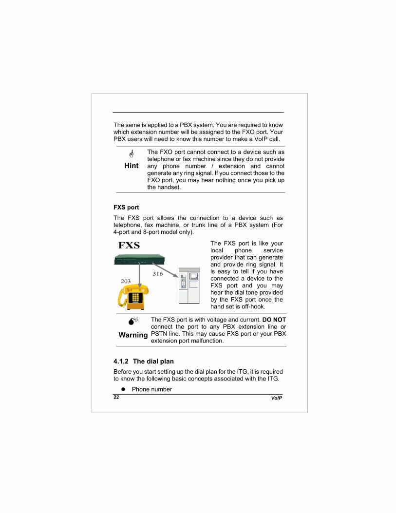
FXS port The FXS port allows the connection to a device such as telephone, fax machine, or trunk line of a PBX system (For 4-port and 8-port model only).
The FXS port is like your local phone service provider that can generate and provide ring signal. It is easy to tell if you have connected a device to the FXS port and you may hear the dial tone provided by the FXS port once the hand set is off-hook.
Warning
The FXS port is with voltage and current. DO NOT connect the port to any PBX extension line or PSTN line. This may cause FXS port or your PBX extension port malfunction.
4.1.2 The dial plan Before you start setting up the dial plan for the ITG, it is required to know the following basic concepts associated with the ITG.
Phone number
FXS
203316

ITG Quick Installation Guide 23
Hunt Group ID
Destination ID
Destination
1) Phone Number
The “Phone number” associated with the ITG is a set of digits. You may look at that as an area code associated with your phone number. This number will only map to one Hunt Group in this example. You may reference to Section 5 for more details regarding configuration and Dial Plan examples.
Number Hunt GroupOne To One
‘408’ ‘10’ 2) Hunt Group ID
The “Hunt Group ID” here is an interpreter between phone number and Destination ID. The ITG phone table will be based on the number you dial to find the related hunt group. So, different numbers may map to the same hunt group. A Hunt group consists of at least one Destination ID. It means that when a call is placed the first available Line Destination ID will be connected.
Hunt Group Destination ID One To One
‘10’ ‘10’
Hint
In this guide, we will only set up one Hunt Group to one Destination.
This will be convenient for you to trace the relations.

VoIP 24
3) Destination ID and Destination The “Destination ID” here is an interpreter between Hunt Group and physical Destination. Hunt Groups may map to the same destination ID.
The destination is either a physical port or a remote IP address that ITG should make a call to. Each Destination ID maps to a physical destination. There are two types of physical destination.
A physical port on the ITG, i.e. the FXO/FXS port
A H.323 VoIP gateway with a fixed IP address or a host name.
Destination ID Destination One To One ‘1’ ‘0’ ‘10’ ‘mary01.dyndns.org’
Hint
In this guide, we will use a dial plan table as below for illustration purpose. Number
Hunt Group
Dest. ID
Destination
201
1
1
0

ITG Quick Installation Guide 25
408
10
10
mary01.dyndns.org
‘201’ is a default number, ‘408’ is a new number we will add onto the table.
4.2 Console Configuration & Commands To start up the console management, we will show you some often used console commands first.
The major command for the dial plan set up is “atpm”.
The following will show you how to set up your dial plan using the command “atpm”.
Hint
Key in ‘atpm’ command without any parameters first and it will prompt the available parameters for your quick reference.
Warning
After power on the ITG, all the information such as dial plan, port settings in the flash memory will be copied to the memory.
If you have made any changes to it, you are required to restore new records from memory back to the flash memory so you do not loss it when power on occurs.
4.2.1 ‘atpm’ command For setting up your ITG the first time, you may use the following command lists to check all your current tables.
1) atpm alist ; show you the phone number or address table

VoIP 26
2) atpm hlist ; show you the hunt group table
3) atpm dlist ; show you the destination table
1) atpm alist After key in the command ‘atpm alist’ you will find the default table as below: (Note: For a 2-port ITG model)
Address Entry
Hunt Group ID
Min Digits
Max Digits
Prefix Strip
Prefix Address
201 1 0 3 3 None 202 2 0 3 3 None
Min Digits/Max Digits: Once the handset is off hook and you start to dial, the ITG will wait for the digits before it looks up the Hunt Group. For example, if the Maximum Digits are 2 and you dial “201”, before you press “1” the ITG already starts up the process.
Hint
Some times, limit the maximum digits will speed up the call process by the ITG.
Also, if you would like to control the long distance calls through your FXO port, say Internet call through your PBX to make an International call with phone number “011-886-3-5679728”. You set the max. digits to cut the dial.
Prefix Strip/ Address: As any phone system, your phone number is set according to “country code- area code- local number” .For example ‘886-3-5679728’. In a local area, you don’t need to receive the number ‘886-3’. The Prefix Strip here is to strip out dial. The preset number of digits for you, the prefix Address is to add the predefined number of digits to the number for you.
For example: Prefix Strip 4 digits

ITG Quick Installation Guide 27
886-3-5679728 ITG 5679728 Remote ITG
In this example your ITG will stripe ‘886 3’ before sending the number ‘5679728’ to the remote ITG.
To add prefix number 5679 to the digits,
728 ITG 5679-728 Remote ITG
In this example the local ITG will add ‘5679’ then send ‘5679728’ to the remote ITG.
Warning
If you think your dial plan is correct but couldn’t reach the destination, you may want to check if you’ve stripped out or addressed more digits to your number incorrectly.
2) atpm hlist Now, let’s use the command “atpm hlist” to display the Hunt Group table.
Console>atpm hlist <enter>
Hunt Group Type # of Dest. ID Dest. ID1 2 1 1 2 2 1 2
Type 1 is to hunt for the next available port and Type 2 is for the first available one. The default value is “2”, and “# of Dest. ID” is the amount of Destination ID in this hunt group.
Hunt Group Type # of Dest. ID Dest. ID10 2 1 10 11 2 2 11 1
This example shows that Hunt Group 11 has two destinations.
3) atpm dlist The command “atpm dlist” is to display the Destinations
Console>atpm dlist <enter>

VoIP 28
Dest. ID Mode Destination 1 Local 0 2 Local 1
It has two types of Mode, Local and Remote. Local is the physical ports on your ITG. If your ITG is a 2-port model, it will display as above. Remote means that the target is a H.323 device.
Dest. ID Mode Destination 10 H.323 211.20.96.5 11 dns mary01.dyndns.org
Now, let’s add some phone numbers to the ITG. The commands we will used are:
4) atpm req : request for database update
5) atpm aadd : add a new phone number
6) atpm hadd : add a new Hunt Group
7) atpm dadd : add a new Destination
8) atpm done : close the database
9) atpm store : save the changes from memory to the flash memory.
4) atpm req
Accompany with the command ‘atpm done’ both commands are used to inform the ITG that we are going to make changes to the phone system or complete the changes.
Hint
Without this request command, you will fail in using the following three commands.

ITG Quick Installation Guide 29
Warning
During the ‘atpm req’ set up period, all the connection and dial process will be torn down. It is strongly recommended that you do not connect your ITG to the network before executing this command!
5) atpm aadd
With this command you may add a new phone number to the ITG. For example, add a number ‘408’ to the ITG where hunt group is 10 and we want to strip ‘408’ 3 digit.
Console>atpm aadd 408 3 6 10 3 <enter>
The number 3 and 6 are the minimum digits and maximum digits. (The allowed range is between 0 and 16)
6) atpm hadd
When adding a phone number, hadd is used to add a new Hunt Groups. For example, let’s add a new Hunt Group 10 and its destination to 10, the command is:
Console>atpm hadd 10 2 10 <enter>
The number 2 hers is the hunt type. We suggest that you use this default number.
7) atpm dadd
Here we intend to add a physical port or a physical H.323 gateway. For example, let’s add a new destination to the IP address ‘211.20.96.5’ to Destination ID, 10.
Console>atpm dadd 10 h323 211.20.96.5 <enter>

VoIP 30
The parameter H323 here is to tell the ITG the destination is a H.323 gateway. If you know its host name, you may do the following:
Console>atpm dadd 11 dns mary01.dyndns.org <enter>
8) atpm done
This command is used to inform your ITG to close the Dial Plan database.
9) atpm store
This command is used to store all your settings from memory to the flash memory. Without this command, all the settings will disappear if you power off the ITG.

ITG Quick Installation Guide 31
5.CONFIGURAITON EXAMPLES
5.1 The default dial-plans Before any configuration set up, your ITG should have the following basic information. Network: IP : 192.168.0.1 Mask: : 255.255.255.0 Gateway : 0.0.0.0
Dial Plan:
No. Hunt Group
Dest. ID
Dest.
201 1 1 0 (local port #1) 202 2 2 1 (local port #2) 203 3 3 2 204 4 4 3 20X X X (x-1)
(X is from 1 to 8, and it varies depending on your ITG model)
If your ITG’s two FXS ports are connected to two telephones, say port 1 and port 2 respectively, just pick up phone 1 and dial ‘202’, phone 2 should ring. 202 ITG local
port #2 )))
Hint
You may also check the LED indicators on the ITG. When it rings, the related LED should flash. After you pick up the handset, it should remain on and off
h th h i h k
FXS
201 202

VoIP 32
when the phone is on hook.
Now let’s test your ITG that is equipped with FXO interface. Assume you have one extension line with your PBX system, say, 316 as the extension number, we connect this line to ITG’s port 1 (FXO port), then connect a telephone phone set to port 3 (for example) of the ITG.
FXO
316
FXS
203
100
Pick up your extension handset, for example, 100 and dial ‘316’. After one ring, you should hear a dial tone. Now press ‘203’ then the telephone connected to the ITG’s FXS port should ring.
Hint
If you do not hear the dial tone, please check the line impedance of your PBX. For an ITG with FXO port, you should find a Guide for setting the appropriate line impedance in your package. Please set it up accordingly to adjust your FXO port.

ITG Quick Installation Guide 33
Now let’s make a call to your extension. Pick up the handset connected to the FXS port and dial ‘201’, you should hear a dial tone (This means that ITG picks up the line connected to your PBX). Then dial ‘100’, your extension handset should ring right away.
Hint
This guide only uses the default values. Once you are familiar with the dial plan set up, you may design your own. You may set it up with only one digit, ‘1’ and ‘100’ rings.
5.2 ITG to ITG in the Static IP Address
Environment The previous section shows you how to test your ITG without modifying any settings. This section will show you how to connect two ITGs together and make VoIP calls. Assume that we have a second ITG, say ITG B, with the default setting as well. Now, let’s set up the IP address to, e.g. ‘192.168.0.2’ and connect it to ITG A with the following three steps. Step 1.
ITG B:
Console>net set ip 192.168.0.2 <enter> and restart. ITG B
Step2. Connect ITG A and ITG B to the same Ethernet switch or hub.
Step3.
ITG A:
Console>ping 192.168.0.2 <enter> ; ping ITG B Ping (192.168.0.2) 56 data byte 192.168.0.2 is alive

VoIP 34
ITG B: Console>ping 192.168.0.1 <enter> ; ping ITG A
Ping (192.168.0.1) 56 data byte 192.168.0.1 is alive
After these three steps, both ITGs may find each other on the same network. Now let’s set up the remote H.323 gateway for each other.
ITG A: Console>atpm req <enter> Console>atpm aadd 02 2 5 10 2 <enter> Console>atpm hadd 10 2 10 <enter> Console>atpm dadd 10 h323 192.168.0.2 <enter> Console>atpm done <enter> Console>atpm store <enter> ITG B: Console>atpm req <enter> Console>atpm aadd 01 2 5 10 2 <enter> Console>atpm hadd 10 2 10 <enter> Console>atpm dadd 10 h323 192.168.0.1 <enter> Console>atpm done <enter>
Console>atpm store <enter>
The dial plan for these two ITGs should add a new record after the above commands.
ITG A:
No. Hunt Group Dest. ID Dest. 02 10 10 192.168.0.2
ITG B:
No. Hunt Group Dest. ID Dest. 01 10 10 192.168.0.1

ITG Quick Installation Guide 35
Now, once ITG A gets a dialed number “02” it will direct the call to ITG B. The same is to ITG B, ‘01’ will map to ITG A without a doubt.
ITGA
203
ITGB
203
01 02
Assume both ITGs have a FXS port on port#3 with a phone set connected. To call each others.
ITG A:
Pick up handset and dial “02203”, where ‘02’ points to ITG B and ‘203’ for port 3 of ITG B. The phone attached to ITG B should ring.
ITG B:
Pick up the handset and dial “01203”, where ‘01’ points to ITG A and ‘203’ is designated for port 3 of ITG A. The phone attached to ITG A should ring.
Hint
In this example, we assign to each ITG with a unique number. You may treat that number as an area code. Each ITG represents a different area.
ITG A is with area code 01 and ITG B is with code 02. So. If you have more, you may assign to the next ITG with, 03, 04, etc.

VoIP 36
Hint
If you can not hear the ring signal, please do make sure of the following: 1) Both ITG can ping each other 2) You are connected to a correct port. In this
example, it should be the FXS port. Also the phone number will be “20X” where X corresponds to the location of the port.
3) Make sure you’ve stripped the number in the command “atpm aadd” correctly.
We may continue to use the configuration mentioned in Section 4.1 for PBX connections.
316
100
ITGA
203
ITG B
203
01 02
201
ITG A:
The users at ext. 100 wants to make a call to ITG B, 203. What we need to do is to pick up the handset with extension ‘100’ and dial ‘316’. After you hear the dial tone again, dial ’02-203’. Then, the phone attached to ITG B should ring.
ITG B:
If users at ITG B want to make a call to ext 100 through ITG A, one should dial, ’01-201’ where the PBX line is connect to port 1. After hearing the dial tone, just dial the extension number ‘100’.

ITG Quick Installation Guide 37
Hint
Imagine how we use the PBX with our extension handset. We pick up the handset and dial any extension number directly to your co-workers, and dial ‘0’ or ‘9’ to make a call to PSTN network.
The same is with ITG B, after you dial “01-201”, you can do the same thing because “01201” connects you to the extension handset 316. In this scenario the handset with extension 203 connected to ITG B may also be looked as an extension of the PBX.
After all of above, your ITG should perform normally. Let’s do the following two things:
A) Convert the IP address, Mask, and Gateway to your network that can access the Internet. Do the same thing to your second, and third ITG so they may connect to the Internet as well.
B) Check the bandwidth, and the router. Normally, if you can ping each other, it means that they should talk to each other via VoIP calls.
Warning
Please make sure your router will not block the IP port. The port used for ITG with the default settings are: TCP: 1024 ~5000 UDP: 30000 ~31000
Warning
The average bandwidth for each channel is from 12kbps to 16kbps by default. In a heavy traffic network, the available bandwidth between two nodes may affect the voice quality.

VoIP 38
5.3 ITG to ITG in the Dynamic IP Address Environment
The previous section shows the steps regarding how to set up a typical ITG-to-ITG connection in the static IP address environment without modifying any settings. This section we will show you how to connect two ITGs in a dynamic IP address environment via built-in PPPoE, DHCP, and DDNS clients.
Assuming there is a second ITG, say ITG B, located on site B with default settings. First of all, it is required to apply for a DDNS host name from http://www.dyndns.org for ITGs on site A and site B. (For example, the names are mary01.dyndns.org for ITG on site A, and mary02.dyndns.org for ITG on site B.)
mary01.dyndns.org is applied for ITG on site A,
mary02.dyndns.org is applied for ITG on site B.
Other parameters on this topology : ITG on site A has PPPoE, and DDNS clients enabled
ITG on site B has DHCP, and DDNS clients enabled.
Network topology can be shown as follows:

ITG Quick Installation Guide 39
ITG configuration (ADSL PPPoE connection) on site A: PPPoE section:
Please fill in username/ password obtained from ISP.
net set pppoe on <enter> net set pppoe user_name my_name <enter>net set pppoe pw my_password <enter>
DDNS Name:mary02.dyndns.org
(216.94.170.66)
DDNS Name:mary01.dyndns.org
(61.155.107.86)Area 886 Area 408
408
886

VoIP 40
DDNS client section:
Dialplan settings: Create an address entry for ITG on site B
ITG configuration (cable connection) on site B: DHCP section:
.
DNS server section: DNS server settings will not take effect till system reboot.
atpm req <enter> atpm dadd 408 dns mary02.dyndns.org <enter>atpm hadd 408 2 408 <enter> atpm aadd 408 2 8 408 3 <enter> atpm done <enter> atpm store <enter>
set dyndns add dyndns mary01 my_name my_password <enter>
config store <enter>
net reset <enter>
net set dhcp on <enter> then press ”y” or use command net reset to rebooting
set h323 dns_ip 168.95.1.1 <enter>
config activate <enter> config store <enter>

ITG Quick Installation Guide 41
DDNS client section
Please fill in username and password obtained from ISP.
Dialplan section: Create an address entry for ITG on site A
After these modifications, users on site A are able to dial “408 + telephone number” to call users on site B to have voice conversation. Users on site B are able to have voice communication by dialing number “886 + telephone number” toward users on site A. (Please note that there is a Max digits (8) limitation of dial string in this case, users may modify this parameter to meet different needs.)
Warning
If calls can not be made, please check: a. connectivity between ITGs is correct. (This
may be checked via ping command in ITG.)
b. DDNS name is correctly updated.
set dyndns add dyndns mary02 username password <enter>
config store <enter>
net reset <enter>
atpm req <enter> atpm dadd 886 dns mary01.dyndns.org <enter> atpm hadd 886 2 886 <enter> atpm aadd 886 2 8 886 3 <enter> atpm done <enter> atpm store <enter>

VoIP 42
5.4 PBX related issues There are some issues related to PBX system. There are: 1) CP (Call Progress) Tone detection, and 2) Call Security
5.4.1 CP Tone Detection You may encounter a problem when your call goes to PBX via a VoIP connection, the caller may already hang up the phone but the PBX port is still active.
The cause of this problem may be due to the CP tone mismatch. The ITG can not understand the Tone from PBX. So it still considers the line is on and never hangs up.
Once this happened, you may find a technical document provided by your vendor to fix this problem.
5.4.2 Call Security
The ITG is a standard H.323 VoIP gateway that will allow any standard H.323 device to make a VoIP call to it. That means no matter where you are, once you have a H.323 device such as another ITG, or a software package such as Microsoft NetMeeting, you may make a call to this ITG any time once it connects to the Internet.
If the ITG is only equipped with FXS port, that should be okay, but once it is connected with PBX or PSTN, you are opening a phone line for any Internet users to make a call. For example, you may have an International call to Europe though an ITG in Singapore even you are in Hong Kong.
To prevent this from happening, you are required to do the following:
1) Restrict the line’s right to use. For example, if the line goes to an extension line, ask the PBX manager to restrict this line from dialing to certain numbers. Or ask the PSTN provider to limit the line usage as well.

ITG Quick Installation Guide 43
2) Re-check the dial table. Check the dial plan table that only allows certain numbers may make calls. That is, remove the unnecessary numbers and restrict the maximum digit or prefix the allowed number inside ITG instead of allowing users dial the number herself /himself.

VoIP 44
This page is intentionally left blank!
