interrupt shearing test for evaluating effect of large … shearing test for evaluating effect of...
TRANSCRIPT

Interrupt Shearing Test for Evaluating Effect of Large Shear Deformationon Evolution of Microstructure into Ultrafine Grains
Jun Yanagimoto1, Sumio Sugiyama1, Shuji Kawando2,+ and Akira Yanagida3
1Institute of Industrial Science, The University of Tokyo, Tokyo 153-8505, Japan2Graduate School of Engineering, The University of Tokyo, Tokyo 153-8505, Japan3Department of Mechanical Engineering, Tokyo Denki University, Tokyo 101-8457, Japan
A new physical simulation method for evaluating the effect of shear deformation on the evolution of a microstructure is proposed. Thismethod utilizes a high-speed compression testing machine and is capable of simulating the formation of fine grained steels in the transformationroute. The outline of the proposed method, which is based on shearing and named the ‘interrupt shearing test’, is presented. The result of thepreliminary application of the newly proposed test at an elevated temperature is shown. It becomes clear that the large shear deformationreproduced by the proposed method is capable of producing fine grained steels with a grain size of around 2 µm surrounded by high angle grainboundaries (HAGBs), although controlled cooling immediately after plastic deformation to accelerate transformation into finer grains is notapplied in the present test. [doi:10.2320/matertrans.MD201119]
(Received July 28, 2011; Accepted September 12, 2011; Published November 2, 2011)
Keywords: interrupt shearing test, physical simulation, severe shear deformation, ultrafine grained steel, niobium microalloyed steel,accerelated transformation, microstructure analysis
1. Introduction
There are strong social demands on lightweight con-structions, such as lightweight vehicles and efficient heatexchangers, to realize the efficient use of energy. High-strength structural metals with high specific tensile strengthsare indispensable for realizing the above lightweight con-structions, and the future environmentally conscious societynecessitates these metals with fewer alloying elements. Onepromising method that meets the above social demands is theuse of a metal with an ultrafine grained structure, such asa bulk nanostructured metal. Such a metal should havesufficient elongation as well as sufficient weldability, becauseit will be part of a lightweight construction after metalforming, such as sheet metal forming, and cold forging andwelding.
A marked number of investigations on the formation ofa bulk nanostructured metal by using a severe plasticdeformation (SPD) process have been performed,15) andmost of them use nonferrous alloys with diversified chemicalcompositions and various alloying elements. At the sametime, steel still occupies the largest share as a structure metal,and this situation will continue for the time being. In fact,aiming at producing ultrafine grained steels, several inves-tigations on the SPD of steel have been performed over thepast decade.68) There are two process routes that produceultrafine grained ferritic steels, namely, ferrite recrystalliza-tion and transformation routes, as is shown in Fig. 1.9) As forthe first recrystallization route, warm shape rolling and otherSPD processes are utilized, and ultrafine grained steels with agrain size of 1 µm are successfully generated.1013) A smallernumber of investigations are performed for the transforma-tion route, but a high-speed controlled rolling or multistagecompression process is used to generate ultrafine grainedplain carbon steels with a grain size of around 1µm.1416) Thefirst route is promising for obtaining finer grains because the
grain growth rate is lower at a lower temperature, but, as isusual in high strength metals, ultrafine grains that includemany dislocations may deteriorate formability. Grain refine-ment thorough accelerated transformation from deformedaustenite is promising for the formation of fine-grainedsteels.17) However, the formation of ultrafine grains by thetransformation route is more difficult owing to the largerdriving force for the change in microstructure in the austenitestate at an elevated temperature. Thus, rather few inves-tigations are performed to generate nanostructured steelsby the SPD process in the transformation route.11,18) Todetermine the process conditions for the formation ofnanostructured steels in the transformation route, detailedinvestigations by physical simulation and numerical analysiswill be required.
At present, hot compression test is widely used toreproduce the evolution of microstructure in hot formingprocess. Compressive deformation is the accumulation ofshear deformation in a macroscopic viewpoint as is explainedby G. I. Taylor19) and, furthermore, the effect of sheardeformation on grain refinement is attracting more attentionbut is not still sufficiently clarified. Torsion test is capable ofvalidating the effect of shear deformation to microstructureevolution, but requires a special testing machine and strainrate is limited.20) A new physical simulation method for
Austenite
SPD
Cooling
UFG FerriteFerrite
SPD
UFG Ferrite
Transformation route
Ferrite recrystallization route
Cooling
Fig. 1 Two routes of grain refinement of ferritic steels.
+Graduate Student, The University of Tokyo
Materials Transactions, Vol. 53, No. 1 (2012) pp. 2 to 7Special Issue on Advanced Materials Science in Bulk Nanostructured Metals©2011 The Japan Institute of Metals

evaluating the effect of shear deformation on the evolution ofa microstructure is proposed. This method utilizes a high-speed compression testing machine and is capable ofsimulating the formation of fine grained steels in thetransformation route. As the proposed test utilizes the high-speed compression testing machine, controlled shear defor-mation with high strain rate can be easily imposed on thespecimen. The outline of the proposed method, which isbased on shearing and named the ‘interrupt shearing test’, ispresented in this paper. The result of the preliminaryapplication of the newly proposed test at an elevatedtemperature reveals that a large shear deformation resultsin fine grained steels with a grain size of around 2µmsurrounded by high-angle grain boundaries (HAGBs) whosemisorientation angle exceeds 15 degree, even under aircooling conditions after plastic deformation.
2. Experimental Procedure
2.1 Construction of interrupt shearing testThe high-speed hot forming simulator14) used in the
physical simulation is shown in Fig. 2. This equipment iscapable of simulating high-speed multistage deformations,such as tandem hot strip rolling, with the highest ram speedof 4000mm·s¹1 and the minimum interpass time of 0.3 s. Ifthe specimen height is 12mm, which is the standard size ofthe specimen for compression by the hot forming simulator,the maximum strain rate exceeds 300 s¹1, which covers thedeformation rate range in high-speed tandem hot strip rolling.The controlling system for temperature is also shown inFig. 2. By comparing the target temperature history andthe actual one measured by a thermocouple welded to acontrolling point of the steel sheet, and controlling theelectric current of the induction heating unit by the PIDalgorithm, the temperature of the controlling point of the steelsheet, where the thermocouple is welded, is expected tofollow the target temperature history.
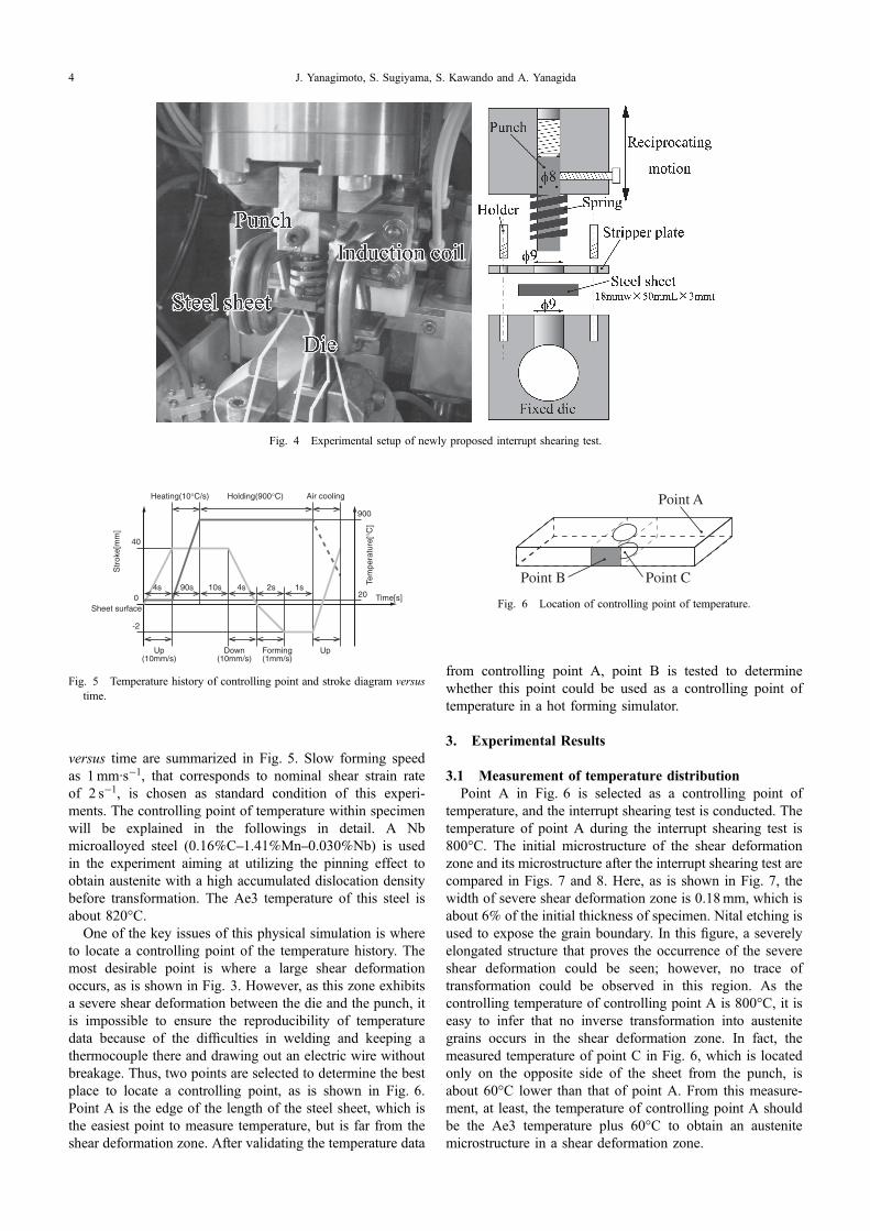
Aiming at imposing a large amount of shear deformationon a steel sheet, the new physical simulation method, that is,the interrupt shearing test, has been developed on the basisof a shearing process, by which a large amount of sheardeformation can be imposed on the steel specimen, as isshown in Fig. 3. To realize the shear deformation inside thehot forming simulator shown in Fig. 3, an experimental setupof the punch and die is newly designed and installed in the
experimental chamber of the hot forming simulator, as isshown in Fig. 4. This method is based on shearing, butdeformation is terminated before breaking the steel. Byinterrupting shear deformation with the predetermined strokeof the punch and the gap between the punch and the die, thetarget shear deformation is applied, and shear bands anddislocations could be introduced into the metal as steelsheets at an elevated temperature. The subsequent controlledcooling is expected to realize the accelerated transformationinto fine grained ferrite-pearlite structures because of theelevated driving force of transformation and increases in thenumbers of nucleation sites and their activities for trans-formation.
2.2 Experimental conditionsThe interrupt shearing test in a hole section is conducted in
this investigation. As is shown in Fig. 4, the punch diameteris 8mm and the die hole diameter is 9mm. Thus, the gapbetween the die and the punch ¦c in Fig. 3, which is arepresentative parameter in the interrupt shearing test, is0.5mm. The sheet thickness h and final punch stroke ¦h are3mm and 2mm, respectively; thus, the nominal shear strain£, defined by,
£ ¼ �h
�c; ð1Þ
under these physical simulation conditions is 4, which isin the severe plastic deformation (SPD) range. The sheetlength and width are 18mm and 50mm, respectively. Thetemperature history of a controlling point and stroke diagram
Punch
Die
Steel sheet
Induction coilThermocouple
PIDcontroller
Electric current of induction heating
t(s)
T(°C) Targettemperature
Spring
Control signal
Stripper plate
Fig. 2 Schematic view of high-speed multistage hot forming simulator and its controlling system for temperature.
Shear deformation zone
Material flow
Δc
Δh
Fig. 3 Local deformation induced by industrial shearing.
Interrupt Shearing Test for Evaluating Effect of Shear Deformation 3
versus time are summarized in Fig. 5. Slow forming speedas 1mm·s¹1, that corresponds to nominal shear strain rateof 2 s¹1, is chosen as standard condition of this experi-ments. The controlling point of temperature within specimenwill be explained in the followings in detail. A Nbmicroalloyed steel (0.16%C1.41%Mn0.030%Nb) is usedin the experiment aiming at utilizing the pinning effect toobtain austenite with a high accumulated dislocation densitybefore transformation. The Ae3 temperature of this steel isabout 820°C.
One of the key issues of this physical simulation is whereto locate a controlling point of the temperature history. Themost desirable point is where a large shear deformationoccurs, as is shown in Fig. 3. However, as this zone exhibitsa severe shear deformation between the die and the punch, itis impossible to ensure the reproducibility of temperaturedata because of the difficulties in welding and keeping athermocouple there and drawing out an electric wire withoutbreakage. Thus, two points are selected to determine the bestplace to locate a controlling point, as is shown in Fig. 6.Point A is the edge of the length of the steel sheet, which isthe easiest point to measure temperature, but is far from theshear deformation zone. After validating the temperature data
from controlling point A, point B is tested to determinewhether this point could be used as a controlling point oftemperature in a hot forming simulator.
3. Experimental Results
3.1 Measurement of temperature distributionPoint A in Fig. 6 is selected as a controlling point of
temperature, and the interrupt shearing test is conducted. Thetemperature of point A during the interrupt shearing test is800°C. The initial microstructure of the shear deformationzone and its microstructure after the interrupt shearing test arecompared in Figs. 7 and 8. Here, as is shown in Fig. 7, thewidth of severe shear deformation zone is 0.18mm, which isabout 6% of the initial thickness of specimen. Nital etching isused to expose the grain boundary. In this figure, a severelyelongated structure that proves the occurrence of the severeshear deformation could be seen; however, no trace oftransformation could be observed in this region. As thecontrolling temperature of controlling point A is 800°C, it iseasy to infer that no inverse transformation into austenitegrains occurs in the shear deformation zone. In fact, themeasured temperature of point C in Fig. 6, which is locatedonly on the opposite side of the sheet from the punch, isabout 60°C lower than that of point A. From this measure-ment, at least, the temperature of controlling point A shouldbe the Ae3 temperature plus 60°C to obtain an austenitemicrostructure in a shear deformation zone.
Fig. 4 Experimental setup of newly proposed interrupt shearing test.
Holding(900°C) Air coolingHeating(10°C/s)
10s 1s
40
-2
Str
oke[
mm
]
090s 2s4s4s
Tem
pera
ture
[°C
]
900
20 Time[s]Sheet surface
Forming(1mm/s)
Down(10mm/s)
Up(10mm/s)
Up
Fig. 5 Temperature history of controlling point and stroke diagram versustime.
Point CPoint B
Point A
Fig. 6 Location of controlling point of temperature.
J. Yanagimoto, S. Sugiyama, S. Kawando and A. Yanagida4

3.2 Fine grained structures after hot interrupt shearingtest
From the above measurements, it was clarified that thetemperature of a controlling point should exceed 820°C plus60°C. Thus, the target temperature is selected as 900°C andthe temperature of point B, which is closer to the sheardeformation zone, is selected as a controlling point. Themacroscopic view of the steel sheet after the interruptshearing test is shown in Fig. 9. The boundary misorientationmap of the shear deformation zone and that of an adjacentzone with a small plastic deformation are compared inFig. 10. Scope of field in EBSD (electron backscatterdiffraction) analysis is 200 µm © 200 µm and step size is
0.5 µm. IPF in Fig. 11 shows that typical transformedmicrostructure with random orientation is obtained afterinterrupt shearing test. It is clear that shear deformationpromotes grain refinement, and grains are equiaxed duringtransformation. Also, these boundary misorientation mapsshow that almost all grain boundaries are high-angle ones.The linear intercept measurement of the structure shows thatthe grain size of the shear deformation zone lies between1.8 µm and 2.7 µm. As is shown in Fig. 5, a fine grainedmicrostructure composed of HAGBs is obtained, even thoughno accelerated cooling is applied to the steel sheet after theinterrupt shearing test. This result may indicate that a steelstructure with several hundred nanometer ferrite-pearlite-bainite grains could be obtained after the optimization ofthe cooling conditions immediately after shear deformation,which is reproduced by the newly developed physicalsimulation method. This is a challenging target for the steelsheets, and, in order to reach this goal, we should seek thebest combination of process parameters, such as plasticdeformation and transient change in temperature,21,22) thatcould be obtained by the physical simulation methodproposed in this paper.
4. Conclusion
A new physical simulation method for evaluating the effectof shear deformation on the formation of a nanostructuredmetal is proposed in this paper. As the proposed methodutilizes a high-speed hot forming simulator, microstructureevolution at an elevated temperature could be quantitativelyexamined, including the grain refinement of steels into finegrained ones via transformation. The preliminary applicationof the proposed method to niobium steel shows that amicrostructure with an average grain size of 2 µm andHAGBs is generated in the shear deformation zone, even
(a) (b)
Fig. 8 Initial microstructure (left) and microstructure of shear deformation zone after interrupt shearing test.
Fig. 9 Macroscopic view of steel sheet after interrupt shearing test.Fig. 7 Macroscopic view of shear deformation zone.
Interrupt Shearing Test for Evaluating Effect of Shear Deformation 5

though no controlled cooling to accelerate transformationinto fine grains is applied in the test. Further investigationsare required to obtain nanostructured steel with a grain size ofseveral hundred nanometers by the newly developed physicalsimulation method.
Acknowledgement
This study was financially supported by a Grant-in-Aidfor Scientific Research on Innovative Area, “BulkNanostructured Metals”, through MEXT, Japan (contractNo. 22102005).
REFERENCES
1) A. Azushima, R. Kopp, A. Korhonen, D. Y. Yang, F. Micari, G. D.Lahoti, P. Groche, J. Yanagimoto, N. Tsuji, A. Rosochowski and A.Yanagida: CIRP Ann. Manuf. Technol. 57 (2008) 716735.
2) R. Z. Valiev, R. K. Islamgaliev and I. V. Alexandrov: Prog. Mater. Sci.45 (2000) 103189.
3) For example, R. Z. Valiev: Mater. Sci. Forum 503504 (2006) 310.4) B. Cherukuri, T. S. Nedkova and R. Srinivasan: Mater. Sci. Eng. A
410411 (2005) 394397.5) T. C. Lowe: JOM 58 (2006) 2832.6) N. Tsuji, Y. Saito, S. H. Lee and Y. Minamino: Adv. Eng. Mater. 5
(2003) 338344.7) K. T. Park, S. Y. Han, D. H. Shin, Y. K. Lee, K. J. Lee and K. S. Lee:
Reference zone without plastic deformation
Shear deformation zone
Shear deformation zoneReference zone without plastic deformation
15°5°2°
180°15°5°
Boundaries: Rotation AngleMin Max
50μm50μm
Fig. 10 Comparison of boundary misorientation map of shear deformation zone and that of adjacent zone without plastic deformation.
Shear deformation zone
50μm 50μm 50μm
ND(Normal Direction) RD(Reference Direction) TD(Transverse Direction) RD
TD
EBSD coordinate system
ND
Fig. 11 Comparison of inverse pole figure map of shear deformation zone.
J. Yanagimoto, S. Sugiyama, S. Kawando and A. Yanagida6

ISIJ Int. 44 (2004) 10571062.8) A. Yanagida, K. Joko and A. Azushima: J. Mater. Process. Tech. 201
(2008) 390394.9) S. Torizuka: Bull. Iron Steel Inst. Jpn. 10 (2005) 188195.10) Y. Hagiwara, M. Niikura, M. Shimotomai, Y. Abe and Y. Shirota:
J. JSTP 42 (2001) 402407.11) S. Torizuka, K. Nagai and A. Sato: J. JSTP 42 (2001) 287292.12) T. Inoue, S. Torizuka and K. Nagai: Tetsu-to-Hagané 86 (2000) 793
800.13) S. Torizuka, T. Inoue and K. Nagai: Tetsu-to-Hagané 86 (2000) 801
806.14) J. Yanagimoto, Y. Kobayashi and A. Yanagida: Steel Res. Int. 78
(2007) 812817.15) M. Etou, S. Fukushima, T. Sasaki, Y. Haraguchi, K. Miyata, M. Wakita,
T. Tomida, N. Imai, M. Yoshida and Y. Okada: ISIJ Int. 48 (2008)11421147.
16) T. Tomida, N. Imai, K. Miyata, S. Fukushima, M. Yoshida, M. Wakita,M. Etou, T. Sasaki, Y. Haraguchi and Y. Okada: ISIJ Int. 48 (2008)11481157.
17) I. Tamura: Trans. ISIJ. 27 (1987) 763779.18) T. Yamashita, S. Torizuka and K. Nagai: ISIJ Int. 43 (2003) 18331841.19) H. Takahashi: Polycrystal Plasticity, (Corona Publishing Co., 1999)
pp. 6869.20) H. Beladi, G. L. Kelly, A. Shokouhi and P. D. Hodgeson: Mater. Sci.
Eng. A 367 (2004) 152161.21) Y. Adachi, T. Tomida and S. Hinotani: Tetsu-to-Hagané 85 (1999) 620
627.22) M. Koiwa: Materia Japan 50 (2011) 5562.
Interrupt Shearing Test for Evaluating Effect of Shear Deformation 7