interskytm system technical overview - new era · pdf fileshiron satellite communications inc....
TRANSCRIPT
Shiron Satellite Communications Inc. Business Confidential
Technical Overview Page 1 of 38 Revision 0.0
Satellite Communications
InterSKYTM System Technical Overview
Presented by:
Shiron Satellite Communications
Contact: Mr. Victor Klejman Telephone: +1-31-896-9373 Facsimile: +1-301-896-9353 E-Mail: [email protected]
March 2002
This document and the information contained in it is proprietary and confidential information of Shiron Satellite Communications (1996) Ltd. No person is allowed to copy, reprint, reproduce or publish any part of it, nor disclose its content to others, make any use of it, unless with the prior express written authorization of Shiron and then only to the extent authorized.

Shiron Satellite Communications Inc. Business Confidential
Technical Overview Page 2 of 38 Revision 0.0
Table of Contents 1 Introduction ....................................................................................................................................................... 4
1.1 Advantages of choosing Shiron InterSKYTM
Integration ................................................................................ 4 1.2 Shiron History................................................................................................................................................. 4 2 General ............................................................................................................................................................... 5
3 General Overview.............................................................................................................................................. 8 3.1 System Description ......................................................................................................................................... 8
3.1.1 DAMA......................................................................................................................................................... 8 3.1.2 BOD............................................................................................................................................................ 9
3.2 InterSKYTM
System Topology......................................................................................................................... 9 4 System configuration....................................................................................................................................... 10 4.1 Hub configuration ......................................................................................................................................... 10 4.2 InterSKY
TM
Remote Gateway........................................................................................................................ 11 4.2.1 Remote Gateway Hardware...................................................................................................................... 12 4.2.2 InterSKY
TM
Remote Network Management Agent (RNMA) .................................................................. 13 4.2.3 End User Configurations.......................................................................................................................... 14
5 General Principle of Operation...................................................................................................................... 16 5.1 Access Method and Basic BOD Operation................................................................................................... 16
5.1.1 System Physical Layout ............................................................................................................................ 16 5.1.2 Bandwidth Management ........................................................................................................................... 16 5.1.3 Connection Channel Assignment.............................................................................................................. 17 5.1.4 Bandwidth on Demand Operation............................................................................................................ 17 5.1.5 Disconnection Process ............................................................................................................................. 17
5.2 Management.................................................................................................................................................. 17 6 VOIP Description ............................................................................................................................................ 18 6.1 Bandwidth Calculations ................................................................................................................................ 18 6.2 FXO .............................................................................................................................................................. 18 6.3 FXS ............................................................................................................................................................... 19 6.4 E1 Connections ............................................................................................................................................. 20 6.5 Voice Quality ................................................................................................................................................ 20
6.5.1 Equipment Sound Quality Enhancements................................................................................................. 20 6.5.2 Voice Quality and Data Traffic ................................................................................................................ 21 6.5.3 Satellite Delay........................................................................................................................................... 21
7 Hub: Detailed Description .............................................................................................................................. 21 7.1 Standard Master Rack Components .............................................................................................................. 21
7.1.1 Network Management System (NMS) Server............................................................................................ 22 7.1.2 Transponder Setup.................................................................................................................................... 22 7.1.3 Traffic Network Management Agent (TNMA) Server ............................................................................... 22 7.1.4 IP Encapsulator (IPE) .............................................................................................................................. 23 7.1.5 KVM Switch .............................................................................................................................................. 23 7.1.6 Ethernet Switch......................................................................................................................................... 23 7.1.7 Master IF Splitter ..................................................................................................................................... 23

Shiron Satellite Communications Inc. Business Confidential
Technical Overview Page 3 of 38 Revision 0.0
7.1.8 Master RS-485 Splitter ............................................................................................................................. 23 7.2 Traffic Rack � IS-DM60R ............................................................................................................................ 23
7.2.1 Ethernet Hub ............................................................................................................................................ 24 7.2.2 Receiver RS-485 Splitter........................................................................................................................... 24 7.2.3 Receiver IF Splitter................................................................................................................................... 24 7.2.4 Demodulator Shelf.................................................................................................................................... 24 7.2.5 DM-384 FDMA Demodulator .................................................................................................................. 25
7.3 Equipment Options ....................................................................................................................................... 25 7.3.1 Accounting and Billing ............................................................................................................................. 25 7.3.2 Voice Over IP ........................................................................................................................................... 26 7.3.3 Gatekeeper................................................................................................................................................ 26 7.3.4 Carrier Class VOIP .................................................................................................................................. 26 7.3.5 VPN........................................................................................................................................................... 27 7.3.6 Protocol Accelerator ................................................................................................................................ 27 7.3.7 Cache........................................................................................................................................................ 28 7.3.8 Video Conference ..................................................................................................................................... 29 7.3.9 Legacy Protocol Support .......................................................................................................................... 31
7.4 System Security............................................................................................................................................. 31 8 Specifications ................................................................................................................................................... 33 8.1 System........................................................................................................................................................... 33 8.2 Forward Link (Outbound)............................................................................................................................. 33 8.3 Hub................................................................................................................................................................ 33 8.4 Receiver ........................................................................................................................................................ 33
8.4.1 DM384...................................................................................................................................................... 33 8.5 Remote Gateway........................................................................................................................................... 35
8.5.1 Indoor Unit ............................................................................................................................................... 35 8.5.2 Transmitter � RG-384B ............................................................................................................................ 35 8.5.3 Receiver .................................................................................................................................................... 35 8.5.4 Outdoor Unit ............................................................................................................................................ 35
8.6 Environmental Conditions (Hub and Remote Units) .................................................................................... 35 8.7 Outdoor Unit ................................................................................................................................................. 36 9 General System Requirements and Functionality Overview ...................................................................... 36 9.1 Compliance Certification .............................................................................................................................. 36 9.2 Outdoor Unit Power...................................................................................................................................... 36 9.3 Reliability & Redundancy............................................................................................................................. 36 9.4 Redundant elements: ..................................................................................................................................... 37 9.5 Redundant Hub ............................................................................................................................................. 37 9.6 Control .......................................................................................................................................................... 37 9.7 Monitoring .................................................................................................................................................... 37 9.8 Maintainability .............................................................................................................................................. 37

Shiron Satellite Communications Inc. Business Confidential
Technical Overview Page 4 of 38 Revision 0.0
1 Introduction Shiron Satellite Communications is pleased to offer a turnkey system for the supply of Two-Way broadband communications. Shiron is continuously developing advanced broadband satellite systems to allow reliable, efficient communications at a low cost for the growing IP base market. The Shiron proposal is based on the company�s own developed and commercially available InterSKY
TM system. The InterSKY
TM system has an extensive customer base with leading satellite service providers. Shiron�s proposal is fully compliant to the RFP, meeting all requirements and in some cases, exceeding them.
1.1 Advantages of choosing Shiron InterSKYTM
Integration The Shiron proposal offers many advantages including:
1. No development needed: System is already available through other major service providers and has mature market base
2. Cost effective: Forward DVB carrier & Return carrier share the same resources 3. Fast delivery schedule allows for fast deployment 4. Turnkey system uses Shiron as single primary supplier 5. Reliable & cost-effective integration 6. Modular and scalable solution for current and future needs 7. Company dedicated to the continuous development of IP based products via satellite
1.2 Shiron History Shiron Satellite Communications is engaged in the development, integration, manufacture and sale of state-of-the-art satellite communication systems. Shiron was the first company to develop and offer a line of satellite L-band modems in both variable and burst capabilities. The modems implement the latest in DSP technology, algorithms, FPGA, and direct digital synthesizer components, all on a dual compact digital board. Since Shiron introduced these modems, other satellite communication companies have invoked the L-band philosophy, which became a standard for all VSAT and Broadband systems. L-band technology was embraced for its reliability and cost.

Shiron Satellite Communications Inc. Business Confidential
Technical Overview Page 5 of 38 Revision 0.0
Figure 1. Shiron SR256L L-band Modulator / Demodulator Digital Cards The modems were designed for VSATs and Hub stations for variety of online applications such as voice, data, and video. The L-band modem provides full support to the outdoor Remote Frequency Terminal (RFT). Shiron also introduced a low cost VSAT for satellite networks using low cost Block up-Converters that use L-band IF input and convert to standard Ku-band or C-band frequencies. The development objectives of this project were successfully achieved by mid-1998. During the project, the company developed a proprietary innovative technology and a novel system architecture, which resulted in a significant cost reduction of the modem and the complete VSAT. Since 1997, Shiron has been engaged in the development and introduction of the Two-Way via Satellite Broadband Network System. Shiron was again the first company to commercially offer a Two-Way via satellite broadband network system that is fully IP based. The system incorporates the DVB-S / MPEG2 (Digital Video Broadcasting for Satellite / Moving Picture Experts Group) as the broadcasting waveform mechanism to allow multimedia streaming of Video, Data and Voice on a single wideband channel. The Return path, also via satellite, uses Shiron�s L-band modulator/ demodulator technology. Shiron has also developed its own Network Management System that uses a Bandwidth On Demand protocol with a DAMA (Demand Assigned Multiple Access) controller to efficiently use and control satellite frequency resources. The platform provides voice and data services (including Video Multicasting) for local and regional Internet Access & Service Providers (IAP, ISP), Small Businesses, and Shared Facilities in business campuses, universities, Local Area Networks (LAN) and Wide Area Networks (WAN). All LANs are connected under a star configuration to a central Hub that can share multiple users. The InterSKY
TM Remote Gateway uses a standard Ethernet connection protocol allowing easy installation under a LAN environment. The system can be easily integrated into the existing phone infrastructure to provide both the VoIP and data services required. The proposed system offers the subscriber an efficient, reliable, and cost effective solution in accessing multimedia services and eliminates the long delays in accessing the Internet.
2 General

Shiron Satellite Communications Inc. Business Confidential
Technical Overview Page 6 of 38 Revision 0.0
The InterSKYTM
system was designed from the beginning as a Two-Way via satellite fast Internet access system. The system�s superiority lies in its unique features, which are described below.
1. The InterSKYTM
system has a DVB-S compliant forward link from the InterSKYTM
Hub to the remote terminals, which enables multiplexing of TV and IP over the same signal and enables users to receive TV and IP with the same antenna and equipment. This allows customers to add the InterSKY
TM
Hub to existing Digital TV Hubs with marginal investment.
2. The InterSKYTM
Forward link data rates are between 2.0 - 72 Mbps. This enables the service provider to start with a network that leases small portions of the space segment and later expand the network with a simple NMS command.
3. The InterSKYTM
Return link from the RG-384B Remote Gateways is configured, on the fly, for data rates of 16-384 KBPS. This enables small enterprise connections as well as local ISP connections to the Internet backbone.
4. The InterSKYTM
Remote Gateway is designed to provide the basic routing features and capabilities needed to support Local Area Network users. The Remote Gateway can be connected to Ethernet hub, which enables multiple users to connect to the Internet
5. The InterSKYTM
Remote Gateway includes the latest technology in satellite communications such as an L-band IF interface, low cost Block Up-Converters, and standard DRO LNB units. This creates an exceptional price/performance ratio.
6. The InterSKYTM
system comes with a state-of-the-art Network Management System and provides Demand Assigned Multiple Access (DAMA) and Bandwidth On Demand (BOD).
7. The InterSKYTM
system measured data rates per un-accelerated TCP/IP session of 1-1.5MBPS. The user can have several TCP/IP sessions running on his computer all supporting these data rates.
8. The InterSKYTM
system delivers IP (Internet Protocol) over satellite, ensuring compatibility with any user application.
9. The InterSKYTM
system and Remote Gateways support multiple private and standard IP addresses. This provides flexibility in the network and resource allocation and design.
10. The InterSKYTM
system has been tested with the following applications: Netscape, Explorer, other browsers, FTP software, Video Conferencing, Voice over IP, Distance Learning, IP/TV, Real Video/Audio, VPN, IPSEC, PC Anywhere and others. The system�s open network design allows it to deliver any IP based application.
11. The InterSKYTM
system supports Multicasting to the Remote Gateways.
12. The InterSKYTM
network was designed to support QoS on both the Forward and Return links with flexible capabilities.
13. The InterSKYTM
system can be provided with accounting and billing software.
14. For the Voice Over IP user a Gatekeeper provides authentication of calls. It also provides the pre-paid calling card administrative capabilities.
15. The InterSKYTM
system is the focal point of Shiron efforts, thus ensuring future advanced features and capabilities.

Shiron Satellite Communications Inc. Business Confidential
Technical Overview Page 7 of 38 Revision 0.0
There are several other unique features, but we believe that the list provided above will lead you to the conclusion that the InterSKY
TM
system provides the most advanced and complete solution in the market today.
In this document we have provided a technical description (high level) of the InterSKYTM
system.
InboundBOD/FDMA
Internet Backbone
Router
DemodulatorBank
100BaseT
NMS TNMAIPE
VOIP &PBX
GateKeeper
DVB-S
Modulator
Hub
Corporate HeadQuarters
Branch Office #2VOIP (FXS) and Data
PSTN
Dedicated IP Leased Line Branch Office #1VOIP (FXO) and Data
Figure 2: InterSKY
TM
Corporate Data and VOIP System - General View

Shiron Satellite Communications Inc. Business Confidential
Technical Overview Page 8 of 38 Revision 0.0
3 General Overview
3.1 System Description InterSKY
TM is a Two-Way Communications System via Satellite that provides Fast Internet and Interactive Multimedia, as well as a wide variety of IP applications. The InterSKY
TM
system enables end-users and service providers to bypass terrestrial communication bottlenecks, thus a fast and reliable solution. The InterSKY
TM
system supports all IP transport protocols: TCP/IP, UDP/IP, unicast and multicast addressing. Integrating the Remote Gateway units with base-stations of a Wireless-Data system can extend the range and capability of the remote units to provide service to users located up to 13 KM from the remote units. This implementation is especially useful in suburban and rural scenarios, as the price per single user is dramatically reduced by connecting to a wireless remote unit instead of connecting to an InterSKY
TM
Remote Gateway. There are additional solutions (e.g. EDSL for building connectivity for residential users) to maximize the full performance of the Remote Gateway and to reduce price per user. Shiron will plan for each scenario the optimum solution to achieve the above goals. The wireless-satellite integrated system is useful also in buildings shared by many individual users. A partial list of applications that have been actually tested within the InterSKY
TM
system includes Internet access - TCP/IP, FTP, HTTP, Voice over IP, IP/TV, Real Video/Audio, Distance Learning, VPN, IPSEC, protocol accelerators, and more. The InterSKY
TM
system may be configured as a one-way via satellite, with a terrestrial return link, or a hybrid system. The InterSKY
TM
is a star configuration system. It is comprised of a central Hub and remote terminals, called Remote Gateways, which enable Two-Way communication. InterSKY
TM
enables multiple users to enjoy multimedia applications at unprecedented speeds. Its Forward link DVB-S/MPEG-2 technology can transmit data rates between 2-72 Mbps. A Remote Gateway can handle traffic of 15 Mbps, processing up to 1.1 Mbps per TCP/IP session and more, if accelerated. The Return path from the Remote Gateway to the central Hub, also via satellite, offers data rates of up to 384Kbps and optional rates of up to 2 Mbps for each terminal. Using the DVB-S technology for the Forward link enhances the efficiency of the space segment usage because of the natural feature of broadcasting information to multiple users. The InterSKY
TM
Network Management System (NMS) enables dynamic channel assignment of the Return channels for each Remote Gateway by using Demand Assigned Multiple Access (DAMA), and Bandwidth On Demand (BOD).
3.1.1 DAMA DAMA may be thought of as trunking in the frequency spectrum. The advantage of a DAMA system is that there is no need to assign each terminal its own frequency. Rather, there is a pool of available frequencies that are assigned according to need.

Shiron Satellite Communications Inc. Business Confidential
Technical Overview Page 9 of 38 Revision 0.0
3.1.2 BOD BOD is Shiron Satellite Communications unique application that goes beyond the abilities of DAMA. BOD is based on a combination of software agents that measure the instantaneous bandwidth required by a Remote Gateway. Bounded by a pre-configured range, the Return channel bandwidth allocated to each terminal is dynamically assigned according to the current requirement of the Remote Gateway. By further controlling the power and frequency of each of the Remote Gateways, the system maximizes the efficiency of satellite resource utilization. InterSKY
TM
supports IP QoS (Quality of Service) to maximize the performance of the applications that are of highest priority to the system manager.
3.2 InterSKYTM
System Topology The system is shown in Figure-2. The system consists of a central Hub and Remote Gateways. The Remote Gateways are located at the users� premises. The Hub includes the IF output subsystem, the Return channel subsystem, and the controls. Additional equipment may be connected to the central LAN to provide the features and applications unique to the customer. The Remote Gateway provides Internet Protocol (IP) connectivity. Its interface to the outside world is a standard 10/100Base-T network interface card. The Remote Gateway can be connected to all Ethernet based equipment.

Shiron Satellite Communications Inc. Business Confidential
Technical Overview Page 10 of 38 Revision 0.0
4 System configuration
4.1 Hub configuration General architecture of the Hub is shown in Figure 3.
Main Ethernet Switch
NMS
Hot Swap Redundancy
Backbone
IP Encapsulator
Modulator
1:1 DVB ModulatorSubsystem
Modulator
IP Encapsulator
70 M
Hz
IF
Hot SwapRedundancy
DVB sub-system
NMS Bridge
Router
IP DataAccounting Server
Demodulator Rack
100B
aseT
HU
BSP
485R
L - BandIF from
MSTR
Rack
TNM
A
Return Channel subsystem
GatekeeperE1
PSTN
PBX
CarrierClass VOIPGateway
Cache
Figure 3 - InterSKY� Redundant Hub with Accounting and VOIP
The Hub�s main elements are:
1. DVB Subsystem � Responsible for broadcasting Forward data from Hub to remote terminals. The DVB sub-system converts IP packets to DVB-S format MPEG-2, modulates the baseband signal and transmits the signal (a single carrier) to all of the Remote Gateways. The DVB chain is available with redundant IP Encapsulators and modulators.
2. Return Channel Subsystem � Used in the Two-Way via satellite mode of operation.

Shiron Satellite Communications Inc. Business Confidential
Technical Overview Page 11 of 38 Revision 0.0
It consists of: - Demodulator Bank � Detects the received data from the Remote Gateways and converts it to IP
packets. - Traffic Network Management Agent (TNMA) � Controls the demodulator bank and forwards the
received IP packets to the backbone or another destination through the main Ethernet LAN Switch interface.
All units are modular, allowing for organic growth.
3. Network Management System (NMS) � Allocates satellite Return channels, authorizes users, controls system and satellite resources, monitors Remote Gateway activities, manages bandwidth allocation, provides automatic power control, etc. There are always two NMS units in a system: one is active and the other provides hot-standby backup.
The Hub may also contain a number of optional elements.
1. VOIP Equipment � When VOIP is employed the Hub usually contains a carrier class (E1) connection to the PSTN. Location of this equipment here allows the remotely located VOIP terminals to reach the telephone network with a �single hop�. A Gatekeeper unit will also be required. A Gatekeeper is also known as a Call Agent or Network Administrator. Its function is to identify, control, count and supervise the flow of traffic through the network gate, plus handling terminal and gateway registration, address resolution, bandwidth and admission control.
2. Data Accounting and Billing � These units keep track of all data, on a per IP address basis, that comes to and from the Internet backbone. Details of usage including the time, packet size, and application are stored. The data can be output in a number of formats for the generation of IP billing.
3. ISP Services Subsystem (optional � not shown) � An ISP must provide various types of services besides basic Internet connectivity. There are many ways of improving end-user performance including (but not limited to) server farms, cache, protocol accelerators, and IP Quality of Service. Each offers an improvement of throughput or response time with a different technique.
4. Data Security Subsystem (optional � not shown) � The specific type of data security equipment is intimately related to the end customer base. This equipment may consist of firewall security, virtual private networks (VPN), and multiple networks. Some of this equipment is located at the Hub and other at the remote sites.
5. Video Conference Subsystem (optional � not shown) � This equipment consists of PCs, screens, video cameras, and microphones. In general it is used to communicate with equipment located at remote sites.
6. Interactive Distance Learning Subsystem (optional � not shown) � For distance learning, the optimal place for locating both the necessary servers and the studio are at the Hub. A single system can provide the learning material for hundreds of classrooms and thousands of students.
7. E-business Subsystem (optional � not shown) � A server farm with e-business applications can be used to service both InterSKY
TM
system users and Internet users. The configuring of this equipment is closely related to the data security policy and ISP services.
8. Push Content Subsystem (optional � not shown) � The purpose of this subsystem is to deliver the same data simultaneously to multiple sites. The content can be either streaming data (IP/TV, web radio) or content (web pages, IP movies) to local cache servers. These are typically powerful servers with complex software.
4.2 InterSKYTM
Remote Gateway The RG-384 is shown in Figure 4.
Shiron Satellite Communications Inc. Business Confidential
Technical Overview Page 12 of 38 Revision 0.0
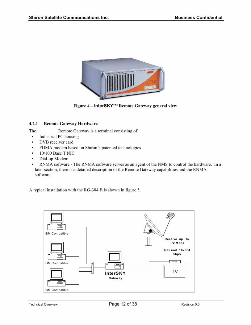
Figure 4 � InterSKY� Remote Gateway general view
4.2.1 Remote Gateway Hardware The
Remote Gateway is a terminal consisting of • Industrial PC housing • DVB receiver card • FDMA modem based on Shiron�s patented technologies • 10/100 Base T NIC • Dial-up Modem • RNMA software - The RNMA software serves as an agent of the NMS to control the hardware. In a
later section, there is a detailed description of the Remote Gateway capabilities and the RNMA software.
A typical installation with the RG-384 B is shown in figure 5.
TV
IBM Compatible
Receive up to 72 Mbps
Transmit 16- 384Kbps
InterSKYGateway
IBM Compatible
IBM Compatible

Shiron Satellite Communications Inc. Business Confidential
Technical Overview Page 13 of 39 Revision 0.0
Figure 5 � InterSKYTM
Remote Gateway on shared Video Carrier
The Remote Gateway is composed of indoor and outdoor units. The Remote Gateway Indoor Unit is an Industrial PC-based unit, including a DVB-S receiver for the outbound received signal, with a LAN processor, a satellite L-band modulator and supporting units such as power supply and 10MHz reference for the outdoor unit, Ethernet LAN with 10/100BaseT interface. The Remote Gateway is designed to receive data rates of 2-72 MBPS process up to 15 MBPS (data rate per unaccelerated TCP/IP session of up to 1 MBPS) and transmit data rates of up to 384 KBPS with the standard offering The Remote Gateway Outdoor Unit (ODU) consists of a Block Up Converter, a standard DRO LNB and an antenna. Two elements that manage the Return channel allocation reside in the Remote Gateway:
• RNMA � Remote Network Management Agent � software package that communicates with the NMS and receives the list of available FDMA channels.
• Traffic Analyzer � continuously measures the inbound traffic from users. When the traffic analyzer senses inbound traffic data sent by the users, it reports to the RNMA. The RNMA then requests a channel from the available channel list, with bandwidth according to the measured traffic. If the bandwidth measured by the traffic analyzer changes, the RNMA requests a new channel in accordance with the updated bandwidth. The modulator at the Remote Gateway uses advanced Digital Signal Processing (DSP) technology, housed on a compact digital board. The unique L-band interface (950-1525 MHz) reduces Remote Gateway cost and allows exceptional price-performance ratio.
4.2.2 InterSKYTM
Remote Network Management Agent (RNMA) The RNMA Software resides in the Remote Gateway. It controls the operation of the transmitter and receiver inside the Remote Gateway. It supports the initial connection to the network and monitors the activity of the LAN users. The RNMA enables the NMS to control the Remote Gateway. It continuously monitors the M&C messages broadcast over the DVB Forward channel by the NMS and acts accordingly.

Shiron Satellite Communications Inc. Business Confidential
Technical Overview Page 14 of 38 Revision 0.0
4.2.3 End User Configurations The Remote Gateway provides an RJ-45 Ethernet 100 Base-T output; this gives the unit very high flexibility. Within in a system, each terminal may be configured in a different manner. In most cases, the LAN equipment located at one Remote Gateway communicates directly either with equipment at the Hub or at another Remote Gateway.
4.2.3.1 VOIP For a system with Voice Over IP capabilities, the equipment at the remote site depends on the amount of voice traffic. If only a few call are required, and the local site does not have a PBX, then FSX equipment best suits the customer needs.
FXS IPExtensionsRemote Gateway
On one side a standard telephone connects directly to the FXS equipment. On the other side, the FXS equipment connects directly to the Remote Gateway LAN. However, this is not the only possible configuration. The VOIP portion of the terminal comes in multiple configurations to fit the needs of the site. The FXO and FXS units are available with these features and options:
• Embedded hardware design • 2 and 4 line options • 2 line unit with option to convert both lines to FXO or FXS • 1 or 2 Ethernet ports • Selectable codec • Selectable sampling rate
The basic carrier units comes with the following features:
• Embedded hardware design • E1/T1 selection • Supports all well known signaling protocols • Clock can be configured as master or slave • Versatile configuration
4.2.3.2 VPN

Shiron Satellite Communications Inc. Business Confidential
Technical Overview Page 15 of 38 Revision 0.0
The figure below shows a typical installation with a VPN appliance. The public leg of the device is connected to the Remote Gateway. In this case, the network device has two interfaces. One interface supports a secured network and the other does not. The networks can operate on registered public IP addresses, NAT, or the device can provide addresses using DHCP.
IP
Remote Gateway
Non-SecureDHCP
SecureNAT
VPN Applicance/Firewall
4.2.3.3 Videoconference IP based Video Conference equipment is another end user option. For decent quality audio and video, a bandwidth of between 128-256 KBPS is required. These data rates are within the working range of the Remote Gateway. Video Conferencing is a two-way application.

Shiron Satellite Communications Inc. Business Confidential
Technical Overview Page 16 of 38 Revision 0.0
IP BasedVideoconference Unit
RemoteGateway
TV Monitor
The specific equipment depends on the user requirements. The figure above shows videoconference equipment with a non-IP output. In this case, the videoconference feeds a television monitor.
5 General Principle of Operation
5.1 Access Method and Basic BOD Operation
5.1.1 System Physical Layout The Shiron InterSKY
TM
system is a star-based asymmetric network. On the outbound link, the InterSKY
TM
Hub transmits a shared TDM (Time Division Multiplexed) DVB-S (Digital Video Broadcasting � Satellite), MPEG-2 compatible signal at data rates of 2-72Mbps. All Remote Gateways receive the same signal. The outbound signal is used to transmit data pushed and pulled to/by the Remote Gateways, and to transmit control data to the Remote Gateways. On the inbound link, the Remote Gateway uses a SCPC (Single Channel Per Carrier) FDMA (Frequency Division Multiple Access) carrier with data rates of 16-384 KBPS for transmission of data and networking commands to the Hub. What is unique about the InterSKY
TM
system is that both the operating frequency and the bandwidth are dynamically assigned.
5.1.2 Bandwidth Management The NMS provides bandwidth management in an on-demand environment. Bandwidth management is provided on a single or multiple transponder basis. All space segment portions dedicated for Return channels are shared among the active users and are available for new demands. Sharing is based on an FDMA scheme where each Return channel has its own carrier frequency and bandwidth. The Return channel bandwidth can be any fraction of a transponder. The InterSKY
TM
system allows for the DVB carrier and the Return channels to be located on different transponders. Also, the return channel bandwidth can be in multiple non-contiguous segments.

Shiron Satellite Communications Inc. Business Confidential
Technical Overview Page 17 of 38 Revision 0.0
5.1.3 Connection Channel Assignment During system configuration, the start frequency and stop frequency to be used for Return channels is entered into the NMS. The NMS generates a list of connection channel. The list is broadcast over the DVB channel to all Remote Gateways. The frequency channels are assigned to each Remote Gateway by DAMA (Demand Assigned Multiple Access) only when actual data is sent from the users towards the Hub. The bandwidth of the channel is assigned according to the actual data rate that is measured and is dynamically adapted to the measured data rate. The initial channel assigned to each connection is according to the base system data rate, and then is modified according to the measured traffic. The system operator selects the base system rate according to the service provided. The base system rate is always an integer multiple of 16 KBPS. The RNMA monitors the users� requests for connection based on their measured traffic sensed by the traffic analyzer (no dialer is required), and chooses one of the free return traffic channels to transmit a connection initiation request to the InterSKY
TM
Hub NMS. The NMS then sends an acknowledgment command to the RNMA and updates the list of the free channels that are transmitted every 10 seconds to all of the Remote Gateways.
5.1.4 Bandwidth on Demand Operation If the RNMA senses traffic data rates that are equal or less to the already occupied channel, then the session continues with the same data rate. If the traffic analyzer senses output data that cannot be accommodated by Return channel, then it sends a request for additional bandwidth to the NMS. Assuming that the configuration parameters permit additional bandwidth allocation, the NMS allocates a frequency and new data rate to the Remote Gateway. The RNMA software reconfigures the modem to continue transmission on the newly assigned channel. Therefore, the data rates change dynamically during a connection based upon instantaneous needs.
5.1.5 Disconnection Process When the RNMA senses a total cessation of Return channel traffic, it sends a disconnect request message to the NMS. The NMS acknowledges the request. At this point, a number of actions occur. The Remote Gateway ceases transmission. The NMS adds the released bandwidth back into the free channel list making it available to other terminals. For more information, please see the accompanying white paper describing the advantages of the combination of FDMA, DAMA, and BOD over other access schemes.
5.2 Management Each element in systems is individually configurable. The InterSKY
TM
system is a closed loop system developed by Shiron. Once the Remote Gateway and Traffic Network Management Agent (TNMA) are initially configured, they are managed automatically by the NMS. For connection to a higher-level system, SNMP agents can be made available.

Shiron Satellite Communications Inc. Business Confidential
Technical Overview Page 18 of 38 Revision 0.0
6 VOIP Description
6.1 Bandwidth Calculations Both via satellite and via public Internet bandwidth are expensive commodities. The public telephone system allocates 64 KBPS for a call. In order to save bandwidth, VOIP equipment employs advanced compression and decompression algorithms. The following is a brief explanation of the data rate required to support Voice over IP. There are slight differences between vendors, however the general approach is the same. The G723.1 is the relevant standard for compression of voice calculation below VOIP packets are divided between the header and the data payload (compressed voice). The standard packet size is 118 bytes. Of this (depending on the vendor), the header is 40-46 bytes. The header is composed of four sections: IP header, UDP header, RTP header, and MLPPP header.
While some vendors send packets every 90 milliseconds (11.2 packets per second), others offer variable transmission rates of 30, 60, 90, and 120 milliseconds. Some equipment is auto-ranging in that it finds the optimal data rate for a given pipe. The data rate calculation for a packet sent every 90 millisecond is:
11.2 (packet/second) * 118 (bytes/packet) * 8 (bits/byte) = 10572.8 (bits/second) However, in practice the actual value is even lower due to silence suppression. In the event that one side is listening (no voice to transmit), the voice payload is significantly reduced. During silence the data rate may be as low as 6.7 KBPS. The Shiron Satellite Communications VoiceSky Gateway supports a return channel data rate of up to 384 KBPS. An E1 line contains thirty time slots of voice. Therefore, the Remote Gateway can transmit the VOIP data produced by a full E1. If less conversations are transmitted, than there is no problem for voice and data to share the same Remote Gateway.
6.2 FXO An FXO unit does not provide voltage; it imitates a telephone. An FXO unit provides a two-wire analog connection.
PBX
PSTN
PSTN
FXO#2
FXO#1
InterSKYSatellite IP
Network
IPExtensions IP

Shiron Satellite Communications Inc. Business Confidential
Technical Overview Page 19 of 38 Revision 0.0
The figure above shows a typical FXO VOIP connection at two locations. An FXO unit can either connect directly to the PSTN or it can connect to the PSTN with a PBX in the middle. The drawing also illustrates a simple rule: telephone equipment connects to telephone equipment and IP equipment to IP equipment. It should be noted that each FXO could communicate with almost unlimited number of other VoIP units. The limitation is essentially the number of locations operated by a single system owner. Typical FXO-FXO Data Flow and Operation The best way to understand how a VOIP network functions is to follow a call. A person calling from a telephone anywhere in the world dials the PSTN phone number connected to FXO #1. The FXO box answers the phone and generates a synthetic dial tone. The caller enters a code that defines another VoIP box (for simplicity only one box is shown in the drawing). The call then reaches FXO #2. FXO #2 connects the call to the PBX. At this time, the caller is given two options: he can either dial an extension or enter the digit used to access the PSTN. Multiple FXO units may be connected to a single PBX. The PBX can define a �hunting group� for multiple FXO access.
6.3 FXS FXS equipment is active; it supplies voltage to operate a telephone.
FXS IPExtensionsRemote Gateway
A telephone can be plugged directly into an FXS unit. The FXS unit cannot require a direct connection to either a PBX or the PSTN. When connected to a PBX, an FXS unit simulates a trunk of the telephone system. Typical FXS Data Flow and Operation One of the functions performed by a PBX is to determine the cheapest rate to call a specific destination. This is known as least cost routing (LCR). Based on predefined parameters, the PBX selects the trunk that will minimize the cost of the phone call.

Shiron Satellite Communications Inc. Business Confidential
Technical Overview Page 20 of 38 Revision 0.0
PSTN
FXS
PBX
Trunk
Trunk
IP
Remote Gateway
A person placing an outgoing call from an extension attached to the PBX will dial a number for outside access (typically �9� or some other digit) followed by the desired phone number. The PBX looks at the LCR table to analyze the number. It can either select the PSTN or the FXS equipment for carrying the call to its destination. The selection of PSTN or VoIP equipment is transparent to the person placing the call. Using the LCR table is not the only method for accessing the FXS connection. Alternately, the VoIP connection can be selected by assigning the FXS trunk a unique code. For example, a company that uses VoIP for intra-office communication would assign a prefix digit to access the outside offices. Please be aware that an FXS unit cannot call another FXS unit. It violates the principles of telephone network operation. However, an FXS unit can be matched with an FXO and an FXO can be matched with another FXO.
6.4 E1 Connections For digital PBX systems, an E1 can be connected to the VOIP equipment. This equipment can use any fraction of the E1 line according to configuration. The equipment communicates with the PBX through the digital signaling on the line.
6.5 Voice Quality All the technology may be interesting, but the important issue is the sound of the voice. There are many factors affecting voice quality, each in a different way.
6.5.1 Equipment Sound Quality Enhancements VoIP equipment does not simply transmit voice �as is.� Rather it combines multiple techniques to guarantee the sound quality. Compression and decompression is used to reduce the quantity of data transmitted. This allows data to pass through a smaller pipe, thereby increasing its success of reaching its destination. Echo cancellation is used to remove noise that is generated by reflection in phone lines. Jitter buffering combined with lost packet interpolation cancels out gaps that occur due to packet loss. Taken all together, VoIP equipment provides outstanding sound quality that is far better than that provided in many cases by cellular phones.

Shiron Satellite Communications Inc. Business Confidential
Technical Overview Page 21 of 38 Revision 0.0
6.5.2 Voice Quality and Data Traffic Voice over IP and other IP traffic co-exist on a single network and compete with one another for the available bandwidth. Proper network design is necessary in order to maintain the voice quality. IP Quality of Service is employed to provide the bandwidth required for the number of calls defined by the customer. The InterSKY
TM
system is compatible with industry standard QoS equipment. In the future, the Remote Gateway will have a native QoS agent to provide VoIP with the bandwidth it requires.
6.5.3 Satellite Delay It takes just over 250 milliseconds for a signal transmitted from earth to reach a geo-stationary satellite and to return to earth. In a conversation, a speaker anticipates a response. The round trip time is twice the delay of a single direction, a delay of over ½ second. In the system shown in Figure 2, the Hub has an Internet backbone connection for data communication: a leased line for IP communications with the corporate headquarters, and a PSTN connection for telephone services. A corporation consisting of a headquarters and branch offices use a satellite link for communications. The typical round trip (single hop) delay for a phone call made from the headquarters to a branch office is 600-700 milliseconds. A call from one branch office to another branch office (double hop) is twice as long. Despite this delay, our experience is that customers are very impressed by the sound quality. One of the factors affecting the quality of the voice is jitter. Jitter occurs because IP networks are connectionless. Calls placed between VoIP equipment within the InterSKY
TM
system are relatively free of the jitter present in the public Internet, resulting in a high quality voice transmission.
7 Hub: Detailed Description The InterSKY
TM
Hub, in its minimal configuration, consists of two 44U 19� racks: the Master Rack and a Traffic Rack. The Traffic Rack, or Demodulator Rack, is controlled by the Master Rack. Each Master Rack can control multiple, fully-equipped Traffic Racks. Additional equipment to support specific customer applications may also be located in the Hub
7.1 Standard Master Rack Components The Master Rack includes the components related to the NMS, M&C of the Demodulators at the Hub, Data Broadcasting, interfacing IF and networking. Following is a list of components for a standard Master Rack. The quantities for each product are specified in the Commercial Proposal.
• Fully wired Master Rack • NMS • TNMA • Control Server • IPE • Modulator • IF Redundancy Switch (optional) • Ethernet Switch • KVM Switch • Keyboard and Mouse

Shiron Satellite Communications Inc. Business Confidential
Technical Overview Page 22 of 38 Revision 0.0
• Monitor • IF Splitter and 10 MHz source • RS-485 Splitter • SR-256 Calibration Modem • Remote Gateway IDU
As is noted in the above list, the Hub is a combination of standard commercially available components and custom software and hardware. The sections below will describe the functions of the major components.
7.1.1 Network Management System (NMS) Server The NMS server runs the InterSKY
TM
Network Management Software. Two NMS Servers are configured to provide redundancy. The two NMS computers are identical in configuration and the same NMS software is installed. One unit is always active (Master) and the other is redundant (NMS Redundant). The NMS software includes a hot swap functionality, which ensures proper operation of the system even if the active NMS computer fails. While operating, the NMS continuously sends status information to the Redundant NMS to ensure its databases are matched to the NMS databases. The Redundant NMS monitors the messages coming from the active Master NMS. If the Redundant NMS does not receive a message from the NMS for a predefined period of time (about 15 sec), it concludes that the other NMS is malfunctioning. In such a case, the redundant NMS will replace the failed computer as the master unit. When the failed NMS returns to operation, it becomes the redundant unit. The following list is a short summary of the major NMS functions:
• Bandwidth On Demand (BOD) functionality • Real time bandwidth management • Receiver management in conjunction with TNMA units • User (Remote Gateway) data base • Processing remote sites requests (Connect/Disconnect) • Redundancy (Hot swap) • Monitoring active channels • Automatic Power Control (APC) of return carriers • Automatic Frequency Control (AFC) of return carriers • �Keep Alive� signaling to active Remote Gateways • Return Channel bandwidth accounting messages for RADIUS server • Logging user and system activities • Local system console
7.1.2 Transponder Setup The NMS supports multiple transponder network management. Transponder setup allows for any fractional part of a transponder to be assigned for use.
7.1.3 Traffic Network Management Agent (TNMA) Server The TNMA is responsible for the management and control of the receivers in the Hub. Each TNMA unit can support up to 120 demodulators via four RS-485 communication ports. The TNMA receives instructions from the NMS regarding the configuration of the demodulators. It then configures the demodulators and monitors their operation. The TNMA acts under orders received from the NMS.

Shiron Satellite Communications Inc. Business Confidential
Technical Overview Page 23 of 38 Revision 0.0
The TNMA also has routing capabilities. It forwards the IP packets received from the Remote Gateways to the central Hub LAN.
7.1.4 IP Encapsulator (IPE) The IPE connects to the InterSKY
TM
Hub LAN. It encapsulates IP data into DVB packets. The output format is a standard Digital Video Broadcasting (DVB) MPEG2 Transport Stream. The physical output can be either a parallel LVDS or an Asynchronous Serial Interface (ASI). The IPE links directly to a DVB modulator or to an optional DVB MUX (multiplexer). A DVB MUX is used when it is required to add a direct video transmission to the outbound carrier.
7.1.5 KVM Switch A keyboard, video, and mouse switch enables switching the 15� monitor, mouse, and keyboard between the computers housed in the Master Rack. Local control is available for Hub components.
7.1.6 Ethernet Switch An Ethernet switch connects the LAN of the InterSKY
TM
Hub. Each computer in the system is connected to the Ethernet switch via its Ethernet network interface card. The particular switch varies depending on the system. The switch selected is based on the customer requirements. There are small systems where a non-managed switch is sufficient. There are systems that require VLAN operation and hence a managed switch. There are systems with server farms that require IP Level 4 switching. The switch will be selected according to how many of the optional requirements are selected for use with the system.
7.1.7 Master IF Splitter The Master IF Splitter is a piece of equipment designed by Shiron for use in the system. It serves a number of functions.
• The splitter has the input for the L-band signal received from the antenna and LNB/PLL. • The received L-band signal is amplified and has ten outputs for distribution to the Receiver Racks. • The splitter provides DC Voltage and a 10 MHz signal of LNB/PLL if an external source is required. • The splitter contains a highly stable, ovenized crystal oscillator for 10 MHz clock generation. • The 10 MHz signal is amplified and has ten outputs for distribution to the Receiver Racks.
7.1.8 Master RS-485 Splitter SP-485M unit distributes the RS485 bus to the demodulator racks. The splitter is passive. The primary function of the splitter is to simplify wire organization.
7.2 Traffic Rack � IS-DM60R The IS-DM60R is the Traffic Rack and can accommodate up to 60 demodulators. Each demodulator supports one FDMA channel. The IS-DM60 includes six receiver shelves, and distribution units for RS485, IF 10MHz and Ethernet. Each shelf is a 6 U high and includes up to 10 receivers. A general view of a traffic shelf is shown in Figure 6.

Shiron Satellite Communications Inc. Business Confidential
Technical Overview Page 24 of 38 Revision 0.0
Figure 6 - Traffic (Receiver) Rack
7.2.1 Ethernet Hub An Ethernet hub is connected to each Demodulator Shelf. It transfers the IP packets transmitted by the Remote Gateways to the TNMA.
7.2.2 Receiver RS-485 Splitter SP-485R is a passive RS-485 splitter. It has two input ports and six output ports. Each input port is associated with one TNMA RS-485 output. Each output port connects to a Demodulator Shelf. Therefore, each input port controls up to thirty demodulators.
7.2.3 Receiver IF Splitter The SP-10IFR splitter has two inputs; one is for the L-band signal and the other for the 10 MHz signal. Both of these signals come from the SP-10IFM Master IF Splitter. The signals are amplified for distribution to the Demodulator Shelves in the rack.
7.2.4 Demodulator Shelf
The SH-10DM Demodulator Shelf contains up to ten DM-384 demodulators. Each shelf has a dipswitch for setting the RS-485 shelf address. The shelf aggregates the IP data from the demodulators and provides an Ethernet output. The demodulator shelf distributes the L-band, 10 MHz, and RS-485 M&C signals to the individual demodulators.

Shiron Satellite Communications Inc. Business Confidential
Technical Overview Page 25 of 38 Revision 0.0
1 2 310
4 5 6 7 8 9 Slot Positions
Figure 7 - Open Demodulator Shelf with Ten Demodulators
7.2.5 DM-384 FDMA Demodulator
The DM-384 is an FDMA demodulator developed by Shiron Satellite Communications. It is based on proprietary algorithms and hardware to provide the performance necessary to support IP traffic.
7.3 Equipment Options An almost endless number of network elements can be added to the system. Although some elements are unique to the Hub or the remote site, in many cases the equipment can be added at either location. The network elements mentioned here are available from numerous sources. Shiron Satellite Communications recommends specific products in each case. Shiron is responsible for the overall system integration and performance of elements ordered through Shiron. The following sections are only a partial list of equipment approved and tested by Shiron. This section concentrates on the equipment options. Another section is dedicated to the applications provided by the equipment described here.
7.3.1 Accounting and Billing Two network elements combine to provide accounting and billing information in the system. A bridging box views all packets that pass from the backbone to the system. This network element forwards a SYSLOG message to the accounting server for each packet passing through it. This message contains information including the source IP, destination IP, source protocol, destination protocol, and other parameters. A server running special software receives all of these messages. It then uses them to generate the statistics for the accounting and billing. The system operator has a wide selection of reports that can be generated from this information.

Shiron Satellite Communications Inc. Business Confidential
Technical Overview Page 26 of 38 Revision 0.0
The Accounting and Billing Servers are ordered according to the total number of simultaneously active sessions.
The system is also capable of keeping an exact log of the return channel space segment usage. The NMS generates RADIUS compatible messages with the
• Start time
• Stop time
• Data rate
• IP address
A server running RADIUS software tabulates the return channel activity of each Remote Gateway. This allows the system operator to generate billing according to the actual usage of a terminal. It also provides the system operator with an indication of the loading on each terminal.
7.3.2 Voice Over IP
Voice Over IP at the Hub often consists of more powerful equipment than at the remote sites. A PBX is usually present at the Hub. The particular equipment is selected according to the number of calls that need to be processed. The VOIP equipment may consist of FXO units with as few as four ports or carrier class units with multiple E1 connections.
In addition to the PSTN connection, the Gatekeeper is normally located at the Hub. This unit provides both policy and accounting information for every remotely located VOIP unit.
As with other equipment at the Hub, the sizing of the VOIP equipment is related to the call traffic of the customer. The equipment purchased must be sized to meet both the initial need and the future call traffic requirements.
7.3.3 Gatekeeper The Gatekeeper is a Windows NT based computer. It manages various databases. The Gatekeeper keeps a record of all calls with information including:
• Call Source • Call Destination • Time of day • Call duration
The Gatekeeper is responsible for the numbering plan. Another primary function of the unit is to provide authentication of the caller.
7.3.4 Carrier Class VOIP A Carrier Class, high-density gateway, can support multiple T1/E1 connections per chassis. These units form a multi-protocol system that supports H.323, SIP, and MGCP. The Carrier Class unit is based on redundant architecture with no single point of failure. The unit is web manageable with a Java based interface. Normally, the

Shiron Satellite Communications Inc. Business Confidential
Technical Overview Page 27 of 38 Revision 0.0
7.3.5 VPN
VPN equipment is only one aspect of the network system security. The recommended virtual private networking equipment that is recommended is hardware based for maximum throughput and lowest operating system vulnerability.
As with other equipment at the Hub, selecting the proper VPN equipment depends on a number of factors. A basic factor is the number of simultaneous tunnels. Each remotely located VPN unit creates a tunnel with the unit at the central site. If only three customers require VPN connectivity (as described in the Network Segmentation Case Study) then a small inexpensive VPN unit can be installed at the Hub. However, if this is only an initial requirement, then the Hub VPN hardware should be sufficient to handle the future needs.
7.3.6 Protocol Accelerator Protocol Accelerators come in many varieties. Since most Protocol Accelerators are based on proprietary realizations and since there is not standard for Protocol Accelerators one must be very careful in comparison and selection. A Protocol Accelerator that gives stellar performance with one application may have no effect on a second application and may cause the failure of a third application. Therefore, the selection of a Protocol Accelerator is a very sensitive issue.
7.3.6.1 Enhanced TCP and Pre-fetching The most common Internet activities are
• HTTP (web browsing), • FTP (file download), and • POP3 (mail reception).
Invisible to users and the standard applications used (such as MS Internet Explorer, Netscape Communicator, MS Outlook) the protocol accelerator recommended by Shiron substitutes the TCP protocol with a highly efficient and reliable UDP based protocol that is especially designed to be used over high delay and loss intensive networks (e.g. satellite or radio links). In addition you can configure the accelerator to encrypt and compress all data during transmission resulting in an overall efficient and highly secure transmission service. Most application protocols used in today�s Internet are based on top of the TCP protocol. TCP is a well-designed protocol that is highly suitable to be used over low delay bi-directional terrestrial links. But over networks with high delay or with packet loss that is unrelated to network congestion, the use of TCP results in poor data throughput due to:
• The TCP window size algorithm (limiting the maximum throughput per round-trip-time), • The slow-start/congestion window algorithm (which drastically reduces the transmission bandwidth e.g. in case of a single packet loss), • The high back-channel bandwidth needed TCP generates an ACK packet at least for every second data packet received).
The protocol accelerator solution solves the above problems. It involves the installation of equipment and the configuration of existing tools. A proxy server with the accelerator software needs to be installed at the Hub. This box does most of the heavy work. Each Remote Gateway requires protocol accelerator companion client software. Licensing is required for each Remote Gateway that runs the software. Users on the LAN behind each Remote Gateway must configure their browser and mail readers to use the proxy settings. Once this is done, users will sense the improved performance.

Shiron Satellite Communications Inc. Business Confidential
Technical Overview Page 28 of 38 Revision 0.0
7.3.6.2 HTTP Acceleration Hardware There is a new type of accelerator available the specifically improves last mile performance. There are many causes of latency related to loading a web page. One of the major problems is related to the sessions opened between a browser and a web server. Some studies suggest that this can account for up to 80% of the delay associated with loading a web page. Cache will minimize the delay for making the information available however it does not solve the session issue. One solution to this problem is real-time web acceleration. A server of this type is positioned in front of the web servers to accelerate the overall performance. If there are no servers, it can be positioned before the router. This accelerator provides the following benefits:
• It provides a faster response time to the clients - 3 to 4 times; • It increases the capacity of servers by a factor of about 10x to 20x; • It decreases the amount of bandwidth necessary for the Web site - by about 50%.
Note that the last two benefits directly translate into cost-savings:
• Money saved on server resources due to increased server capacity; • Money saved on telecom lines due to the reduced bandwidth requirement.
It is easy to demonstrate a fast return on investment. How does real time acceleration work? The RT Accelerator offloads all the processing of TCP sessions and HTTP requests from the servers, and this normally consumes a lot of surfer resources. To do so, it maintains persistent TCP connections (using HTTP 1.1) both to the users and most importantly to the servers, so that when the thousands of HTTP requests are coming in, they can be transferred to the servers via a small number of pre-established persistent TCP connections. The server efficiency is thus extremely high because it does not have to bother to establish the TCP session; it just throws out the data on the 100Mb/s line. The RT Accelerator box then buffers the data, re-arranges it, and compresses it before sending it back to the user onto a persistent TCP connection again. Any standard browser compatible with HTTP 1.1 does the decompression. The consequence of all those techniques combined in the RT Accelerator provides an acceleration factor between 200% and 400% compared with the same Web site without the RT Accelerator. One final advantage of this accelerator is that it is totally transparent. Other types of accelerator techniques require both the configuration of parameters in all browsers and client licenses. This disadvantage of this accelerator is that it only accelerates HTTP sessions and not other types of IP traffic.
7.3.7 Cache
Cache is a technology that helps the system operator in many different ways. Cache increases the effective bandwidth of the Internet connection. Since cache stores previously retrieved information, the percent of cache hits is equivalent to the effective increase of the connection bandwidth. A second effect of cache is psychological. People want fast response to Internet requests. A cache hit reduces the time to provide information. Therefore, the end user feels better about the service that he is receiving and more likely to stay with the service.
Shiron recommends double caching when the system is used for ISP applications. A powerful cache placed at the Hub saves on backbone connectivity. Small appliance caches located at the Remote Gateways save on the return channel space segment, the DVB space segment, and the backbone bandwidth. These caches can be deployed individually and are independent of one another.

Shiron Satellite Communications Inc. Business Confidential
Technical Overview Page 29 of 38 Revision 0.0
Main Ethernet Switch
NMS
Hot Swap Redundancy
Backbone
IPEncapsulato
r
Modulator
1:1 DVBModulatorSubsystem
Modulator
IPEncapsulato
r
70 M
Hz
IF
Hot SwapRedundancy
Demodulator Rack
100B
aseT
HU
BSP
485R
L - BandIF fromM
STRR
ack
TNM
A
NMS
Cache
RouterIP
Remote Gateway
Cache
InterSKYSatellite IP
Network
As with other equipment at the Hub, the sizing of the cache devices is related to
• The sustained throughput that is related to the bandwidth of the backbone connection and the bandwidth of the space segment. • The number of TCP/IP connections that is determined by the number of simultaneous active end-user computers.
The specification of these parameters is necessary to determine the cache appliance that is right for the customer.
7.3.8 Video Conference
Videoconferencing exists both over telephones (usually ISDN) and over IP. The system operates with video over IP. This is a technology based on industry standards (H.323). Videoconference equipment requires bandwidth; normally it uses a data rate between 128-256 KBPS. Since the Remote Gateway operates at up to 384 KBPS, there is more than enough bandwidth for this application.
IP Videoconferencing is not to be confused with web cameras. Web cameras do not offer either the quality or the features of professional IP video equipment. Besides being able to transmit live video, it is also possible to snap a picture and have it sent to a central location.
In many applications a central site must support a large number of remotely located cameras. In this case, the central location requires a very high bandwidth connection. The Hub of the system provides exactly this feature.

Shiron Satellite Communications Inc. Business Confidential
Technical Overview Page 30 of 38 Revision 0.0
There are various things that inhibit effective videoconference deployment: • Management of a large number of video endpoints • Quality of Service • Bandwidth Demands • Network Integration
The equipment supplied and recommended by Shiron is capable of overcoming all of these inhibitors. An element specifically designed to manage multiple video endpoints is the heart of the system. It is used to configure the policy to guarantee the quality of service required by the specific application. It serves as a central location for reporting for all video and voice serves that are used. Besides the central site, there are two primary options for remote equipment configuration. There is no difference between the quality of the voice and data transmission and reception. However, there is a difference in the equipment cost and the operation training required in the configurations.
The configuration shown in the figure below uses an IP-based videoconference unit. Operators at the central site remotely control this unit. The operators can move the camera as well as zoom in and zoom out. When the operator digitally snaps a picture, it is automatically saved on the operator�s computer. A TV is used for the video and audio monitoring of the signal received from the central site. No special training is required for the staff at the remote location.
IP BasedVideoconference Unit
RemoteGateway
TV Monitor
Remote IP Based Video Conference Equipment
An alternate configuration uses a PC-based videoconference unit. The unit connects to a PC by the USB bus. A local operator controls this unit; the operator can move the camera as well as zoom in and zoom out. When the operator digitally snaps a picture, it is both saved on the local computer and transmitted to the central site. The PC monitor is also the monitor for the video signal received from the central site. Special training is required for the staff at the remote location.

Shiron Satellite Communications Inc. Business Confidential
Technical Overview Page 31 of 38 Revision 0.0
RemoteGateway
USB-PCVideoconference Unit
Remote PC Based Video Conference Equipment
7.3.9 Legacy Protocol Support The system is an IP system over Ethernet. Many legacy protocols are not IP based or they do not Ethernet based. However, this does not represent a problem. Ever since the advent of IP over Ethernet there have been devices that convert existing protocols and interfaces to this format. Routers, besides supporting routing protocols, often serve the function of converting from one protocol to another. The following is a partial list of the protocols and interfaces for the system:
• X.25 o X.25 DTE o X.25 Switching (DCE) o RFC 877/1356 (IP) o X.25 Translation, CUG, NUI Support o MX.25 Multidrop
• ISDN o U: ANSI T1.601 1992 (2B1Q) o S/T: ITU I.430 o LAPD: ITU Q.921 Compliant o Q.931 Dial Support
• Frame Relay o Frame Relay DTE with Traffic Fairness o Frame Relay Switching (DCE) o Frame Relay Annex G o Frame Relay RFC 1490 (IP/IPX/Apple Talk) o Local Management Interface o BECN, CIR, BC Support o FRF 12
Information about other protocols is available upon request.
7.4 System Security System security is not something that will be solved by installing a single specific device; there is no panacea. System security is a combination of network planning, security devices, on going maintenance, and customer requirements. Topics such as measures for data encryption, network intrusion detection, and denial of service attacks are only part of the picture.

Shiron Satellite Communications Inc. Business Confidential
Technical Overview Page 32 of 38 Revision 0.0
This section will touch on some of the aspects of network protection; it is not intended to be a definitive work on IP network security. However, it should be clear that the network security requirements is not the same at all customer sites. E-Commerce has a different set of requirements from operating ISP POPs that is different than the requirements of Interactive Distance Learning. Therefore, this section will present some principles of network security since there are not enough details to perform full network design at this time.

Shiron Satellite Communications Inc. Business Confidential
Technical Overview Page 33 of 38 Revision 0.0
8 Specifications
8.1 System Network Type Two-way or One-way, Interactive, Star Topology Data Transport Protocols TCP/IP, UDP/IP and Multicast Monitor & Control Protocol SNMP-based via LAN Interface RF Range C, Extended C, Ku, Extended Ku Number of Active Remote Gateways 1000 per Hub Active Remote Gateways per Hub Depends on Hub architecture, 1000 per each NMS IP Applications Support All IP Based Applications
8.2 Forward Link (Outbound) Transmitted Signal Standard DVB-S/ MPEG-2, Broadcast Access TDM Broadband Data Rate 1.5 up to 72 MBPS for code rate 7/8,
Up to 62.2MBPS for code rate ¾, Up to 41.5MBPS for code rate 1/2
Data Throughput • Per unaccelerated TCP/IP Session 1.1 Mbps for Windows NT, 1.6Mbps for Win 95/98/2000 • Per accelerated TCP/IP Over 4 MPBS, limited by bandwidth and servers
8.3 Hub IP Encapsulator Input Interface Ethernet 10/100BaseT (Auto-detect) Transmission Protocol DVB-S/ MPEG-2, Broadcast Modulator IF frequency 70 ± 18 MHz or 140 ± 36 MHz Modulation QPSK (as per DVB-S) Coding RS (204,188) and Convolutional (as per DVB-S) Signal Level 0 ÷ -20 dBm
8.4 Receiver
8.4.1 DM384 IF Range 950-1525 MHz Access FDMA Modulation QPSK (SQRT Raised Cosine alpha=0.35) M & C Interface RS485 Decoding Convolutional Code R=1/2, 3/4Viterbi Decoding Channel Rate 16-256 KBPS Information Rate 16-384 KBPS Input L-Band Signal Level -65 to -35 dBm Max. Composite 0 dBm or +47 dBc

Shiron Satellite Communications Inc. Business Confidential
Technical Overview Page 34 of 38 Revision 0.0
AC Power 95 to 260VAC, 50/60 Hz Mechanical Installation 19� Racks Decoding Convolutional Code R=1/2, 3/4Viterbi Decoding Channel Rate 16-256 KBPS Information Rate 16-384 KBPS

Shiron Satellite Communications Inc. Business Confidential
Technical Overview Page 35 of 38 Revision 0.0
8.5 Remote Gateway
8.5.1 Indoor Unit AC Power 95 to 260 VAC, 50/60 Hz, 150 Watts LAN Interface Ethernet (IEEE 802.3) Operating System Windows NT L-Band Input Connector F-Connector, 75 Ohm L-Band Output Connector N-type, 50 Ohm Dimensions 483 x 442 x 178 (W x D x H) mm
8.5.2 Transmitter � RG-384B IF Range L-band (950-1525 MHz) Access FDMA, DAMA & Bandwidth On-Demand Modulation QPSK (SQRT Raised Cosine, alpha=0.35) Coding Convolutional Code R=1/2, 3/4 Channel Rate 16-256 KSPS Information Rate 16-384 KBPS in 16 Kb/s Resolution Signal Level -25 to -3 dBm Data Interface Input/Output Ethernet, 10/100BaseT, Autodetect Transmission Type Continuous
8.5.3 Receiver Data throughput per terminal 15 Mbps IF Range L-band (950-2150 MHz) Access DVB/S Modulation QPSK (as per DVB-S) Signal Level -65 to -35 dBm
8.5.4 Outdoor Unit RF Frequency Band C, Extended C, Ku, Extended Ku Transmit level C-band: 2÷8 Watt, Ku band: 0.5÷4 Watt Higher power available Receiver Low-cost Standard DRO LNB Power Supply 24 VDC, Supplied via RF Cable Frequency Reference 10 MHz, Supplied via RF Cable
8.6 Environmental Conditions (Hub and Remote Units) Indoor Unit Operating Temperature 0° to +40° C Storage Temperature -25° to +85° C Humidity 5% to 95% Non-Condensing Altitude Up to 10,000 Feet

Shiron Satellite Communications Inc. Business Confidential
Technical Overview Page 36 of 38 Revision 0.0
8.7 Outdoor Unit Operating Temperature -40° to +55° C Storage Temperature -40° to +70° C Relative humidity Up to 100% Altitude Up to 10,000 Feet Standard Compliance FCC, CE, UL Standard Conform DVB-S, IESS-308, ETSI TBR 28
9 General System Requirements and Functionality Overview
9.1 Compliance Certification Shiron Satellite Communications has received a Compliance Certification for UL and CE approval for its SR256L L-band modem, on which the Remote Gateway is based. The Remote Gateway has been declared to be CE compliant and has received UL and FCC (Part 15, Subpart B, Class B) approval.
9.2 Outdoor Unit Power The Indoor and Outdoor RF equipment is connected by a RG6 and a RJ8 coaxial cable. The Indoor unit supplies the RF signal, DC power, and 10 MHz clock to be carried out to the Block Up Converter through a single high resistance cable. The Rx cable handles only the signal and provides 14 VDC to power the LNB.
9.3 Reliability & Redundancy The following is a list of the major components and their associated MTBF. The calculations are based on a serial model, which assumes that any failure of any component results in a system failure. This is the worst-case state.
( )∑ +++=
n
MTBFλλλ .....
1
21
MTBF --- Mean Time Between Failures;
iλ --- The predicted failure rate of the component i, for operation conditions Component MTBF (hours) Ku-band BUC 65,000 C-band BUC 65,000 C-band LNB DRO 100,000 Ku-band LNB DRO 100,000 RG 384B 30,000 NMS Server 65,000 DVB Modulator 70,000

Shiron Satellite Communications Inc. Business Confidential
Technical Overview Page 37 of 38 Revision 0.0
IP - Encapsulator 70,000 DM-384 Demodulator 365,000 Demodulator Shelf 295,000
9.4 Redundant elements: Redundant Hub: NMS, TNMA, DVB Chain Redundant remote route (terrestrial connection via modem and local ISP)
9.5 Redundant Hub The following describes the architecture of the access subsystem of the main Hub (with redundancy). The NMS and the redundant NMS are the heart of the BOD system. Redundancy of 1:1 is supported by means of hot swap controlled by a software watchdog timer. Each TNMA supports 120 demodulators. A TNMA and the demodulators attached to it make a cluster. To get an effective redundancy, one additional cluster is added above the required number to operate the system. In case of TNMA failure, the NMS will assign the corresponding traffic to available demodulators related to other TNMAs. Demodulator redundancy is achieved by assigning traffic from a malfunction demodulator to another free demodulator. Again, free demodulators must be kept in order to enable the redundancy. DVB broadcast chain redundancy is achieved by adding an additional DVB transmit chain. Each chain consists of an IP Encapsulator and modulator. A separate control PC and an IF 1:1 switch control the switch over process.
9.6 Control The Remote Gateway comes with the following Monitor & Control Access channels:
1. The NMS actively controls the Remote Gateway over the DVB channel 2. Via Satellite using a pcANYWHERE software 3. PSTN modem
9.7 Monitoring The InterSKY
TM Network Management System provides continuous monitoring and health checks of the system. The NMS continuously monitors signal strength, Eb/No measurements, power control, and transmission control and channel and user conditions.
9.8 Maintainability The Remote Gateway is easily maintained and all components can be easily replaced. The unit comes with diagnostic software that allows the technician to closely monitor the health of the system and capture any deviances from the recommended specifications.

Shiron Satellite Communications Inc. Business Confidential
Technical Overview Page 38 of 38 Revision 0.0
1. The complete system installation requires a standard VOM and a laptop computer. Shiron supplies
all the necessary software to allow full control of the unit 2. The BUC can be disconnected and tested in less than 5 minutes
3. The Indoor unit can be replaced and configured in less than 30 minutes