intertex firewall (sip proxy) installation and configuration · objectworld communications ... are...
TRANSCRIPT
Objectworld Communications Corp. • 308 Legget Drive • Ottawa, ON • Canada • K2K 1Y6 • T: 613-599-9698 • F: 613-599-7457 •www.objectworld.com
Intertex Firewall (SIP Proxy)
Installation and Configuration
TN047
March 07
P a g e | 2
Objectworld Communications Corp. • 308 Legget Drive • Ottawa, ON • Canada • K2K 1Y6 • T: 613-599-9698 • F: 613-599-7457 •www.objectworld.com
Table of Contents 1 Introduction ................................................................................................................................................... 4
2 Network Address Translation (NAT) ............................................................................................................. 5
3 Typical SIP Trunking Network Diagram ........................................................................................................ 6
4 Objectworld UC Server .................................................................................................................................. 7
4.1 Preparation ........................................................................................................................................... 7
4.2 Configuring SIP Trunking .................................................................................................................... 7
4.2.1 Select Gateway Type ........................................................................................................................ 8
4.2.2 Select Provider ................................................................................................................................. 9
4.2.3 Change ITSP Settings - Signaling .................................................................................................... 9
4.2.4 Change ITSP Settings - Registration ............................................................................................. 11
4.2.5 Change ITSP Settings – Routing and Outbound Proxy ................................................................. 12
4.2.6 Change Gateway Details and Submit ............................................................................................ 13
4.3 Other UC Server Documentation References .................................................................................... 14
4.3.1 Administrator Manual - Section 3.7 - Managing identities .......................................................... 14
4.3.2 Administrator Manual - Section 3.10 - Managing communication systems ............................... 14
5 Intertex Firewall ........................................................................................................................................... 15
5.1 Intertex Operational Modes .............................................................................................................. 15
5.1.1 Router Mode .................................................................................................................................. 15
5.1.2 LAN SIParator Mode ....................................................................................................................... 16
5.2 Network Topologies .......................................................................................................................... 16
5.2.1 Intertex - Router Mode .................................................................................................................. 16
5.2.2 Intertex - LAN SIParator Mode ....................................................................................................... 17
5.3 Licensing ............................................................................................................................................ 17
5.4 Configuration ..................................................................................................................................... 18
5.4.1 Network Configuration .................................................................................................................. 19
5.4.2 Enabling SIP Services ..................................................................................................................... 21
5.4.3 LAN SIParator Mode ....................................................................................................................... 22
5.5 SIP Trunking with Registrations ........................................................................................................ 23
5.5.1 What is a REGISTER?....................................................................................................................... 23
5.5.2 How It Applies to SIP Trunking ..................................................................................................... 23
5.6 SIP Trunking without Registrations .................................................................................................. 24
5.6.1 Static Domain Forwarding ............................................................................................................. 24
5.7 DNS Considerations ........................................................................................................................... 26
5.7.1 Using a Public DNS ........................................................................................................................ 27
5.7.2 Split DNS Configuration ................................................................................................................ 28
6 Troubleshooting .......................................................................................................................................... 29
P a g e | 3
Objectworld Communications Corp. • 308 Legget Drive • Ottawa, ON • Canada • K2K 1Y6 • T: 613-599-9698 • F: 613-599-7457 •www.objectworld.com
6.1 Intertex Tools .................................................................................................................................... 29
6.1.1 Log Settings ................................................................................................................................... 29
6.1.2 Syslog Server .................................................................................................................................. 30
7 Glossary ....................................................................................................................................................... 31
P a g e | 4
Objectworld Communications Corp. • 308 Legget Drive • Ottawa, ON • Canada • K2K 1Y6 • T: 613-599-9698 • F: 613-599-7457 •www.objectworld.com
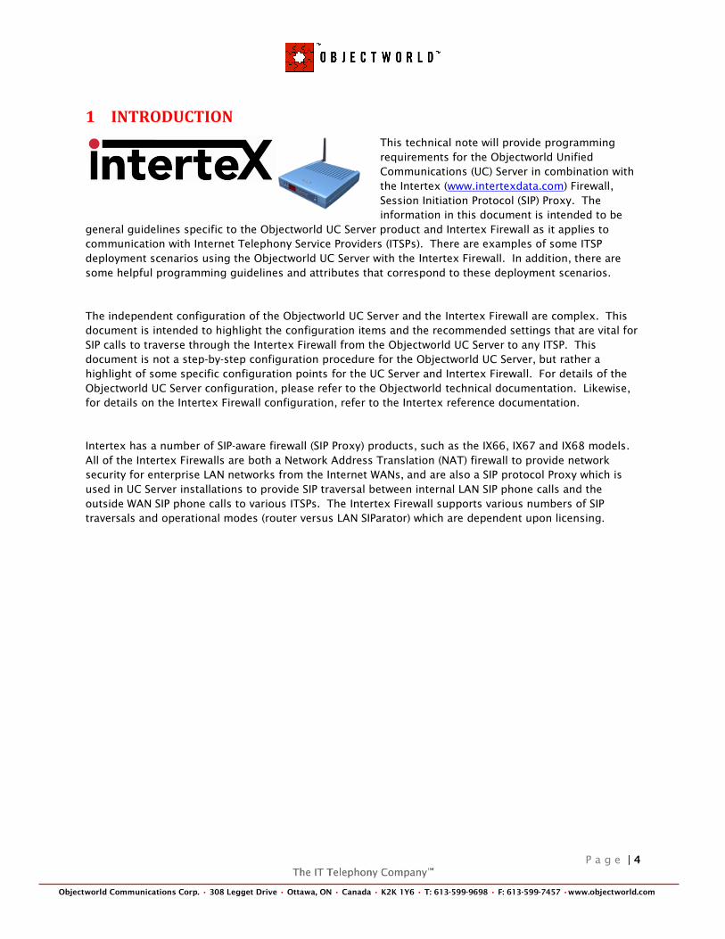
1 INTRODUCTION
This technical note will provide programming
requirements for the Objectworld Unified
Communications (UC) Server in combination with
the Intertex (www.intertexdata.com) Firewall,
Session Initiation Protocol (SIP) Proxy. The
information in this document is intended to be
general guidelines specific to the Objectworld UC Server product and Intertex Firewall as it applies to
communication with Internet Telephony Service Providers (ITSPs). There are examples of some ITSP
deployment scenarios using the Objectworld UC Server with the Intertex Firewall. In addition, there are
some helpful programming guidelines and attributes that correspond to these deployment scenarios.
The independent configuration of the Objectworld UC Server and the Intertex Firewall are complex. This
document is intended to highlight the configuration items and the recommended settings that are vital for
SIP calls to traverse through the Intertex Firewall from the Objectworld UC Server to any ITSP. This
document is not a step-by-step configuration procedure for the Objectworld UC Server, but rather a
highlight of some specific configuration points for the UC Server and Intertex Firewall. For details of the
Objectworld UC Server configuration, please refer to the Objectworld technical documentation. Likewise,
for details on the Intertex Firewall configuration, refer to the Intertex reference documentation.
Intertex has a number of SIP-aware firewall (SIP Proxy) products, such as the IX66, IX67 and IX68 models.
All of the Intertex Firewalls are both a Network Address Translation (NAT) firewall to provide network
security for enterprise LAN networks from the Internet WANs, and are also a SIP protocol Proxy which is
used in UC Server installations to provide SIP traversal between internal LAN SIP phone calls and the
outside WAN SIP phone calls to various ITSPs. The Intertex Firewall supports various numbers of SIP
traversals and operational modes (router versus LAN SIParator) which are dependent upon licensing.
P a g e | 5
Objectworld Communications Corp. • 308 Legget Drive • Ottawa, ON • Canada • K2K 1Y6 • T: 613-599-9698 • F: 613-599-7457 •www.objectworld.com
2 NETWORK ADDRESS TRANSLATION (NAT)
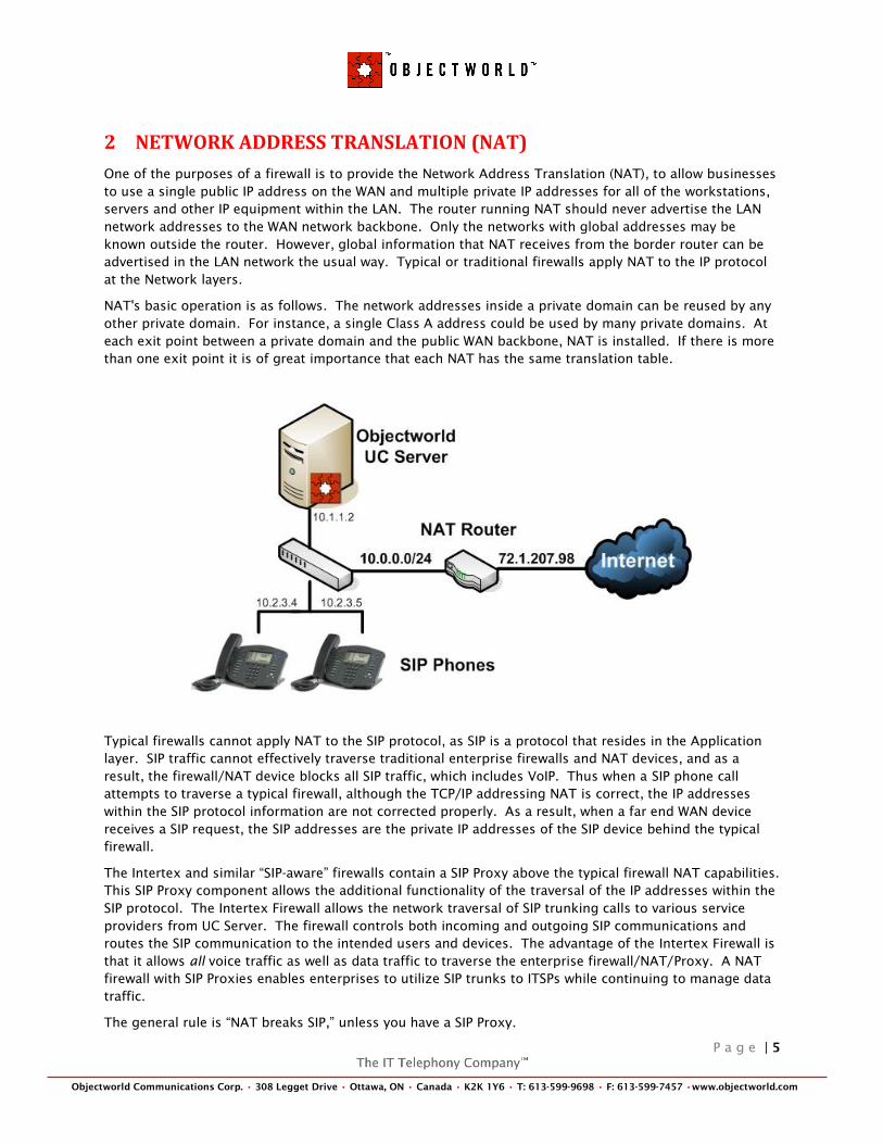
One of the purposes of a firewall is to provide the Network Address Translation (NAT), to allow businesses
to use a single public IP address on the WAN and multiple private IP addresses for all of the workstations,
servers and other IP equipment within the LAN. The router running NAT should never advertise the LAN
network addresses to the WAN network backbone. Only the networks with global addresses may be
known outside the router. However, global information that NAT receives from the border router can be
advertised in the LAN network the usual way. Typical or traditional firewalls apply NAT to the IP protocol
at the Network layers.
NAT's basic operation is as follows. The network addresses inside a private domain can be reused by any
other private domain. For instance, a single Class A address could be used by many private domains. At
each exit point between a private domain and the public WAN backbone, NAT is installed. If there is more
than one exit point it is of great importance that each NAT has the same translation table.
Typical firewalls cannot apply NAT to the SIP protocol, as SIP is a protocol that resides in the Application
layer. SIP traffic cannot effectively traverse traditional enterprise firewalls and NAT devices, and as a
result, the firewall/NAT device blocks all SIP traffic, which includes VoIP. Thus when a SIP phone call
attempts to traverse a typical firewall, although the TCP/IP addressing NAT is correct, the IP addresses
within the SIP protocol information are not corrected properly. As a result, when a far end WAN device
receives a SIP request, the SIP addresses are the private IP addresses of the SIP device behind the typical
firewall.
The Intertex and similar ―SIP-aware‖ firewalls contain a SIP Proxy above the typical firewall NAT capabilities.
This SIP Proxy component allows the additional functionality of the traversal of the IP addresses within the
SIP protocol. The Intertex Firewall allows the network traversal of SIP trunking calls to various service
providers from UC Server. The firewall controls both incoming and outgoing SIP communications and
routes the SIP communication to the intended users and devices. The advantage of the Intertex Firewall is
that it allows all voice traffic as well as data traffic to traverse the enterprise firewall/NAT/Proxy. A NAT
firewall with SIP Proxies enables enterprises to utilize SIP trunks to ITSPs while continuing to manage data
traffic.
The general rule is ―NAT breaks SIP,‖ unless you have a SIP Proxy.
P a g e | 6
Objectworld Communications Corp. • 308 Legget Drive • Ottawa, ON • Canada • K2K 1Y6 • T: 613-599-9698 • F: 613-599-7457 •www.objectworld.com
3 TYPICAL SIP TRUNKING NETWORK DIAGRAM
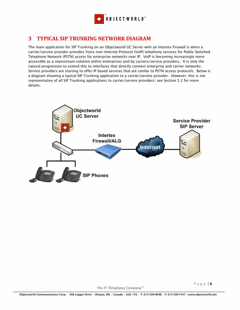
The main application for SIP Trunking on an Objectworld UC Server with an Intertex Firewall is when a
carrier/service provider provides Voice over Internet Protocol (VoIP) telephony services for Public Switched
Telephone Network (PSTN) access for enterprise networks over IP. VoIP is becoming increasingly more
accessible as a mainstream solution within enterprises and by carriers/service providers. It is only the
natural progression to extend this to interfaces that directly connect enterprise and carrier networks.
Service providers are starting to offer IP based services that are similar to PSTN access protocols. Below is
a diagram showing a typical SIP Trunking application to a carrier/service provider. However, this is not
representative of all SIP Trunking applications to carrier/service providers; see Section 5.2 for more
details.

P a g e | 7
Objectworld Communications Corp. • 308 Legget Drive • Ottawa, ON • Canada • K2K 1Y6 • T: 613-599-9698 • F: 613-599-7457 •www.objectworld.com
4 OBJECTWORLD UC SERVER
The information in this section is intended to be general guidelines specific to the Objectworld UC Server
as it applies to the SIP Trunking application and solution using an Intertex Firewall. It is intended to
highlight the configuration items and the recommended settings that are vital for a SIP Trunking call to
traverse through the Intertex Firewall from the SIP Trunking perspective.
4.1 Preparation
Before you begin, the Objectworld UC Server requires some basic information prior to any SIP Trunking
operation. The carrier/service provider typically provides a document listing their connection information
and your account details. Ensure you have the following information:
Required:
The IP address or Fully Qualified Domain Name (FQDN) of the service provider‘s SIP Trunking
Server
The port number (the default is 5060) for the service provider‘s SIP Trunking server
The SIP Trunk Account Number assigned by the service provider
If applicable:
The Registration Authentication Username and Password
The FQDN or IP address of the outbound proxy server and the port number
Any ENUM prefix (+) that is being added to all incoming calls
When using FQDNs, the Objectworld UC Server will require access to a DNS Server on the Intranet and/or
the Internet Public DNS Server will resolve to the service provider‘s domain name.
4.2 Configuring SIP Trunking
Either in the first installation of UC Server or in the Gateway view of the Administration section of UC
Client, you can add an ITSP gateway. The following instructions explain how to set up an ITSP gateway on
UC Server.
1. From the Gateway view on the UC Client, right-click, and select New Gateway to begin configuring
an ITSP Gateway.

P a g e | 8
Objectworld Communications Corp. • 308 Legget Drive • Ottawa, ON • Canada • K2K 1Y6 • T: 613-599-9698 • F: 613-599-7457 •www.objectworld.com
When selecting New Gateway, the Add Gateway Wizard is started.
2. Click Next to add an ITSP.
4.2.1 Select Gateway Type
In the Add Gateway Wizard there are several options to choose from, For SIP Trunking, select
Internet Telephony Service Provider (ITSP).
P a g e | 9
Objectworld Communications Corp. • 308 Legget Drive • Ottawa, ON • Canada • K2K 1Y6 • T: 613-599-9698 • F: 613-599-7457 •www.objectworld.com
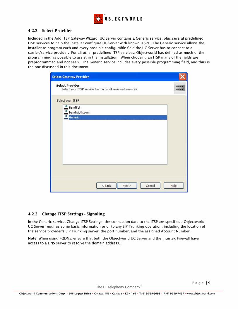
4.2.2 Select Provider
Included in the Add ITSP Gateway Wizard, UC Server contains a Generic service, plus several predefined
ITSP services to help the installer configure UC Server with known ITSPs. The Generic service allows the
installer to program each and every possible configurable field the UC Server has to connect to a
carrier/service provider. For all other predefined ITSP services, Objectworld has defined as much of the
programming as possible to assist in the installation. When choosing an ITSP many of the fields are
preprogrammed and not seen. The Generic service includes every possible programming field, and thus is
the one discussed in this document.
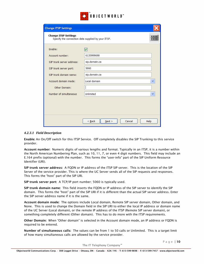
4.2.3 Change ITSP Settings - Signaling
In the Generic service, Change ITSP Settings, the connection data to the ITSP are specified. Objectworld
UC Server requires some basic information prior to any SIP Trunking operation, including the location of
the service provider‗s SIP Trunking server, the port number, and the assigned Account Number.
Note: When using FQDNs, ensure that both the Objectworld UC Server and the Intertex Firewall have
access to a DNS server to resolve the domain address.
P a g e | 10
Objectworld Communications Corp. • 308 Legget Drive • Ottawa, ON • Canada • K2K 1Y6 • T: 613-599-9698 • F: 613-599-7457 •www.objectworld.com
4.2.3.1 Field Description
Enable: An On/Off switch for this ITSP Service. Off completely disables the SIP Trunking to this service
provider.
Account number: Numeric digits of various lengths and format. Typically in an ITSP, it is a number within
the North American Numbering Plan, such as 10, 11, 7, or even 4 digit numbers. This field may include an
E.164 prefix (optional) with the number. This forms the ―user-info‖ part of the SIP Uniform Resource
Identifier (URI).
SIP trunk server address: A FQDN or IP address of the ITSP SIP server. This is the location of the SIP
Server of the service provider. This is where the UC Server sends all of the SIP requests and responses.
This forms the ―host‖ part of the SIP URI.
SIP trunk server port: A TCP/IP port number; 5060 is typically used.
SIP trunk domain name: This field inserts the FQDN or IP address of the SIP server to identify the SIP
domain. This forms the ―host‖ part of the SIP URI if it is different than the actual SIP server address. Enter
the SIP server address name if it is the same.
Account domain mode: The options include Local domain, Remote SIP server domain, Other domain, and
None. This is used to change the Domain field in the SIP URI to either the local IP address or domain name
of the UC Server (Local domain), or the remote IP address of the ITSP (Remote SIP server domain), or
something completely different (Other domain). This has to do more with the ITSP requirements.
Other Domain: When ―Other domain‖ is selected in the Account domain mode, an IP address or FQDN is
required to be entered.
Number of simultaneous calls: The values can be from 1 to 50 calls or Unlimited. This is a target limit
of how many simultaneous calls are allowed by the service provider.
P a g e | 11
Objectworld Communications Corp. • 308 Legget Drive • Ottawa, ON • Canada • K2K 1Y6 • T: 613-599-9698 • F: 613-599-7457 •www.objectworld.com
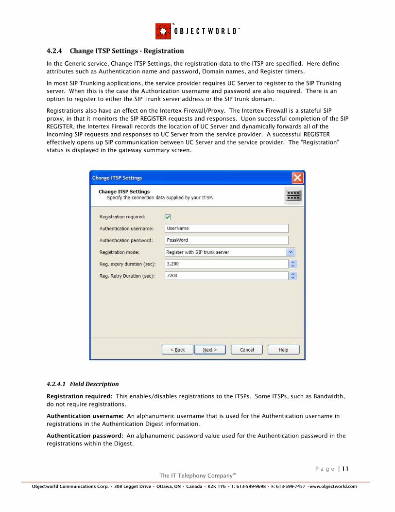
4.2.4 Change ITSP Settings - Registration
In the Generic service, Change ITSP Settings, the registration data to the ITSP are specified. Here define
attributes such as Authentication name and password, Domain names, and Register timers.
In most SIP Trunking applications, the service provider requires UC Server to register to the SIP Trunking
server. When this is the case the Authorization username and password are also required. There is an
option to register to either the SIP Trunk server address or the SIP trunk domain.
Registrations also have an effect on the Intertex Firewall/Proxy. The Intertex Firewall is a stateful SIP
proxy, in that it monitors the SIP REGISTER requests and responses. Upon successful completion of the SIP
REGISTER, the Intertex Firewall records the location of UC Server and dynamically forwards all of the
incoming SIP requests and responses to UC Server from the service provider. A successful REGISTER
effectively opens up SIP communication between UC Server and the service provider. The ―Registration‖
status is displayed in the gateway summary screen.
4.2.4.1 Field Description
Registration required: This enables/disables registrations to the ITSPs. Some ITSPs, such as Bandwidth,
do not require registrations.
Authentication username: An alphanumeric username that is used for the Authentication username in
registrations in the Authentication Digest information.
Authentication password: An alphanumeric password value used for the Authentication password in the
registrations within the Digest.
P a g e | 12
Objectworld Communications Corp. • 308 Legget Drive • Ottawa, ON • Canada • K2K 1Y6 • T: 613-599-9698 • F: 613-599-7457 •www.objectworld.com
Registration mode: When Register with SIP trunk server is enabled, UC Server attempts to register to the
address in the SIP trunk server address field. When Register with SIP trunk domain is enabled, UC Server
attempts to register to the SIP trunk domain address.
Reg. Expiry duration (sec): Sets the Expiry duration on registrations. The Max = 7200 seconds, Min = 10
seconds, and the Default = 3600 seconds.
Reg. Retry duration (sec): If the registration fails, the retry duration refers to how long a wait time until
UC Server tries to register again. The Max = 9600 seconds, Min = 10 seconds, and the Default = 7200
seconds.
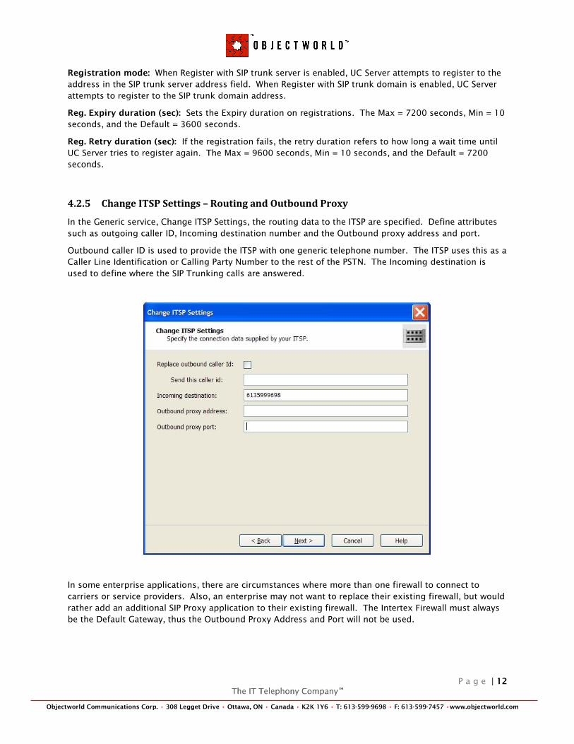
4.2.5 Change ITSP Settings – Routing and Outbound Proxy
In the Generic service, Change ITSP Settings, the routing data to the ITSP are specified. Define attributes
such as outgoing caller ID, Incoming destination number and the Outbound proxy address and port.
Outbound caller ID is used to provide the ITSP with one generic telephone number. The ITSP uses this as a
Caller Line Identification or Calling Party Number to the rest of the PSTN. The Incoming destination is
used to define where the SIP Trunking calls are answered.
In some enterprise applications, there are circumstances where more than one firewall to connect to
carriers or service providers. Also, an enterprise may not want to replace their existing firewall, but would
rather add an additional SIP Proxy application to their existing firewall. The Intertex Firewall must always
be the Default Gateway, thus the Outbound Proxy Address and Port will not be used.
P a g e | 13
Objectworld Communications Corp. • 308 Legget Drive • Ottawa, ON • Canada • K2K 1Y6 • T: 613-599-9698 • F: 613-599-7457 •www.objectworld.com
4.2.5.1 Field Description
Replace outbound caller ID: This value can be either On or Off. This option enables UC Server to
replace/substitute the caller ID with a defined value.
Send this caller ID: This number only can be entered. This is a form of Calling Party Number (CPN)
substitution. This changes the number of the extension number calling, to a general access number or
other defined value.
Incoming destination: This number only can be entered. This is where the incoming dialed number is
defined. This changes the ―user-info‖ of the SIP URI within the Contact Header of the SIP requests.
Outbound proxy address: Enter an IP address or FQDN of the outbound proxy. An outbound proxy is
used when there is a different way out of the network, other than the default gateway.
Outbound proxy port: Enter a port number; usually 5060 is used. This is the port number of the
outbound proxy. An outbound proxy is used when there is a different way out of the network, other than
the default gateway.
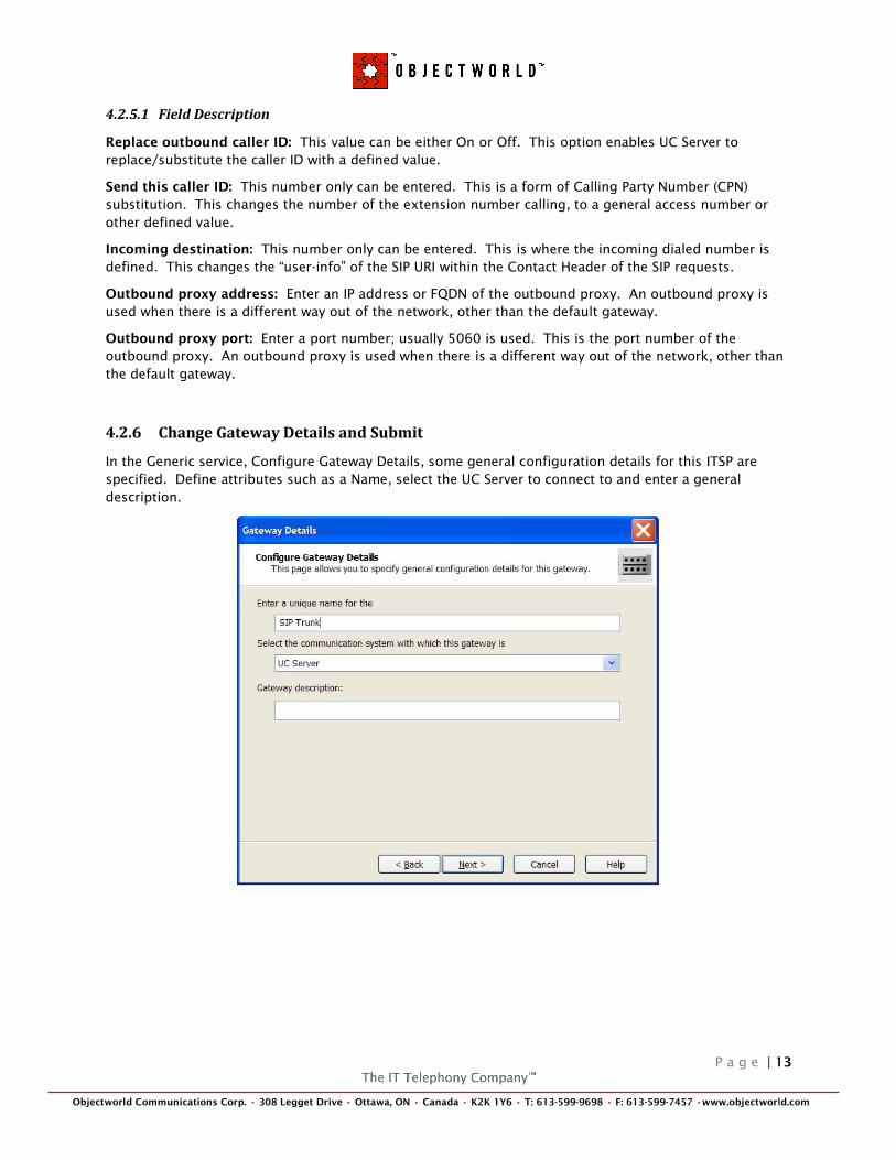
4.2.6 Change Gateway Details and Submit
In the Generic service, Configure Gateway Details, some general configuration details for this ITSP are
specified. Define attributes such as a Name, select the UC Server to connect to and enter a general
description.
P a g e | 14
Objectworld Communications Corp. • 308 Legget Drive • Ottawa, ON • Canada • K2K 1Y6 • T: 613-599-9698 • F: 613-599-7457 •www.objectworld.com
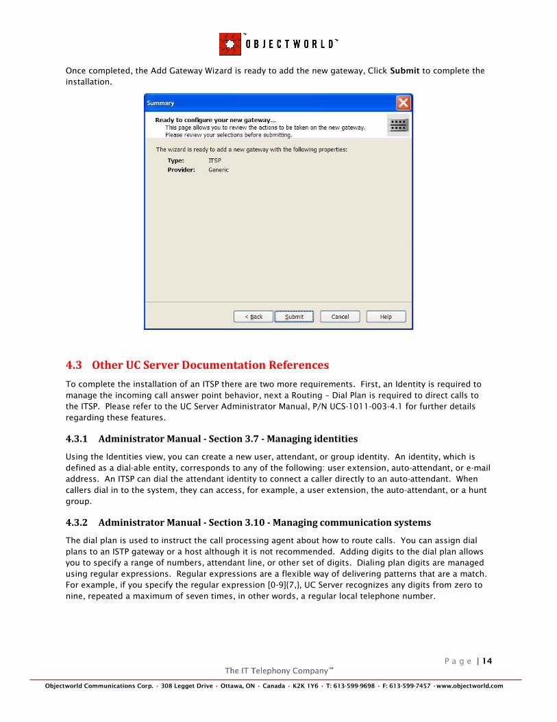
Once completed, the Add Gateway Wizard is ready to add the new gateway, Click Submit to complete the
installation.
4.3 Other UC Server Documentation References
To complete the installation of an ITSP there are two more requirements. First, an Identity is required to
manage the incoming call answer point behavior, next a Routing – Dial Plan is required to direct calls to
the ITSP. Please refer to the UC Server Administrator Manual, P/N UCS-1011-003-4.1 for further details
regarding these features.
4.3.1 Administrator Manual - Section 3.7 - Managing identities
Using the Identities view, you can create a new user, attendant, or group identity. An identity, which is
defined as a dial-able entity, corresponds to any of the following: user extension, auto-attendant, or e-mail
address. An ITSP can dial the attendant identity to connect a caller directly to an auto-attendant. When
callers dial in to the system, they can access, for example, a user extension, the auto-attendant, or a hunt
group.
4.3.2 Administrator Manual - Section 3.10 - Managing communication systems
The dial plan is used to instruct the call processing agent about how to route calls. You can assign dial
plans to an ISTP gateway or a host although it is not recommended. Adding digits to the dial plan allows
you to specify a range of numbers, attendant line, or other set of digits. Dialing plan digits are managed
using regular expressions. Regular expressions are a flexible way of delivering patterns that are a match.
For example, if you specify the regular expression [0-9]{7,}, UC Server recognizes any digits from zero to
nine, repeated a maximum of seven times, in other words, a regular local telephone number.
P a g e | 15
Objectworld Communications Corp. • 308 Legget Drive • Ottawa, ON • Canada • K2K 1Y6 • T: 613-599-9698 • F: 613-599-7457 •www.objectworld.com
5 INTERTEX FIREWALL
The information in this section is intended to be general guidelines specific to the Intertex Firewall
products as it applies to Objectworld‘s UC Server connectivity to carrier/service provider SIP Trunking.
The configuration of Intertex Firewall is complex. This section provides information specific to UC Server
and Intertex settings when configuring for use with a service provider. For more details of the Intertex
Firewall configuration, please refer to the Intertex reference documentation.
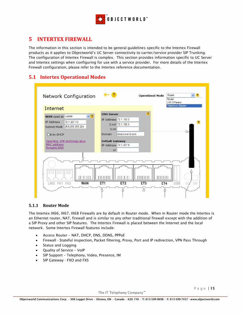
5.1 Intertex Operational Modes
5.1.1 Router Mode
The Intertex IX66, IX67, IX68 Firewalls are by default in Router mode. When in Router mode the Intertex is
an Ethernet router, NAT, firewall and is similar to any other traditional firewall except with the addition of
a SIP Proxy and other SIP features. The Intertex Firewall is placed between the Internet and the local
network. Some Intertex Firewall features include:
Access Router – NAT, DHCP, DNS, DDNS, PPPoE
Firewall - Stateful inspection, Packet filtering, Proxy, Port and IP redirection, VPN Pass Through
Status and Logging
Quality of Service – VoIP
SIP Support – Telephony, Video, Presence, IM
SIP Gateway - FXO and FXS

P a g e | 16
Objectworld Communications Corp. • 308 Legget Drive • Ottawa, ON • Canada • K2K 1Y6 • T: 613-599-9698 • F: 613-599-7457 •www.objectworld.com
5.1.2 LAN SIParator Mode
Intertex also offers a purchasable option called LAN SIParator to change the operational mode of the
Intertex firewall. The LAN SIParator mode is only visible if the option has been purchased; the purpose of
this mode is to allow for SIP and RTP proxy, thus allowing SIP clients behind a non-SIP-aware firewall to
connect to the Internet. The Intertex Firewall is placed behind an existing firewall for proper operation.
The Intertex‘s WAN port becomes an UPLINK port and should be connected to the existing local network.
The ET1-ET4 ports on the Intertex become a switched hub allowing connections of network devices to the
existing local network.
5.2 Network Topologies
The Intertex Firewall and SIParator can be connected to your network in different ways, depending on the
network requirements.
5.2.1 Intertex - Router Mode
In this configuration, the Intertex Firewall must have a public IP address on the WAN interface, while the
rest are connected to the internal network. Internal SIP users and devices must configure the firewall as
the default gateway.
Configuration Steps:
1. By default the Intertex Firewall is in Router mode.
2. To ensure Router mode, select Network under Configuration from the front page.
3. Select Router under the Operational Mode drop down list.
4. Press Save.
P a g e | 17
Objectworld Communications Corp. • 308 Legget Drive • Ottawa, ON • Canada • K2K 1Y6 • T: 613-599-9698 • F: 613-599-7457 •www.objectworld.com
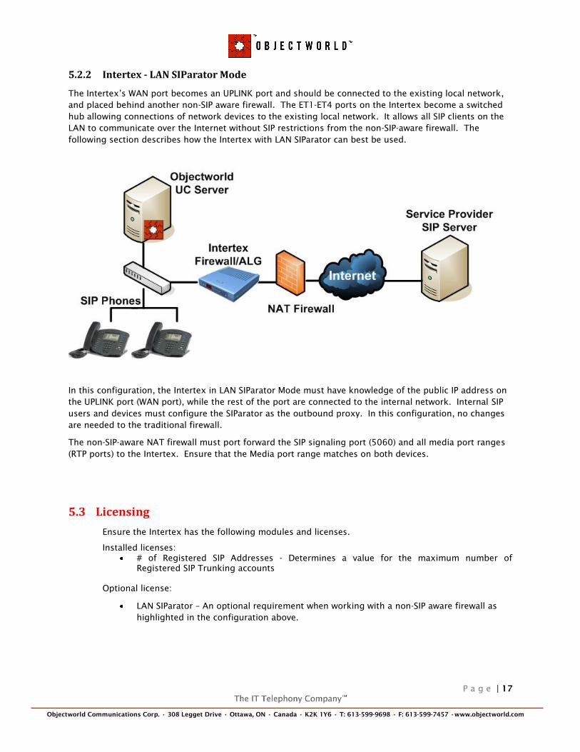
5.2.2 Intertex - LAN SIParator Mode
The Intertex‘s WAN port becomes an UPLINK port and should be connected to the existing local network,
and placed behind another non-SIP aware firewall. The ET1-ET4 ports on the Intertex become a switched
hub allowing connections of network devices to the existing local network. It allows all SIP clients on the
LAN to communicate over the Internet without SIP restrictions from the non-SIP-aware firewall. The
following section describes how the Intertex with LAN SIParator can best be used.
In this configuration, the Intertex in LAN SIParator Mode must have knowledge of the public IP address on
the UPLINK port (WAN port), while the rest of the port are connected to the internal network. Internal SIP
users and devices must configure the SIParator as the outbound proxy. In this configuration, no changes
are needed to the traditional firewall.
The non-SIP-aware NAT firewall must port forward the SIP signaling port (5060) and all media port ranges
(RTP ports) to the Intertex. Ensure that the Media port range matches on both devices.
5.3 Licensing
Ensure the Intertex has the following modules and licenses.
Installed licenses:
# of Registered SIP Addresses - Determines a value for the maximum number of
Registered SIP Trunking accounts
Optional license:
LAN SIParator – An optional requirement when working with a non-SIP aware firewall as
highlighted in the configuration above.
P a g e | 18
Objectworld Communications Corp. • 308 Legget Drive • Ottawa, ON • Canada • K2K 1Y6 • T: 613-599-9698 • F: 613-599-7457 •www.objectworld.com
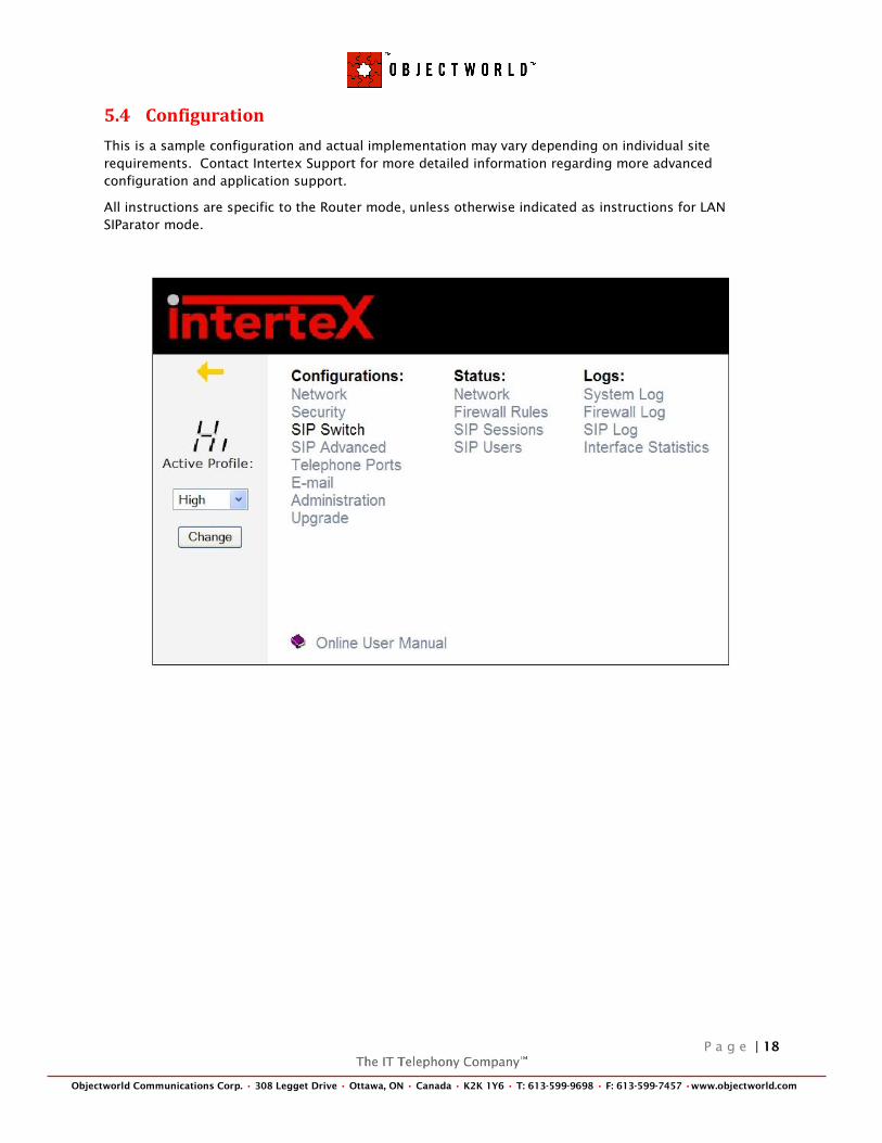
5.4 Configuration
This is a sample configuration and actual implementation may vary depending on individual site
requirements. Contact Intertex Support for more detailed information regarding more advanced
configuration and application support.
All instructions are specific to the Router mode, unless otherwise indicated as instructions for LAN
SIParator mode.
P a g e | 19
Objectworld Communications Corp. • 308 Legget Drive • Ottawa, ON • Canada • K2K 1Y6 • T: 613-599-9698 • F: 613-599-7457 •www.objectworld.com
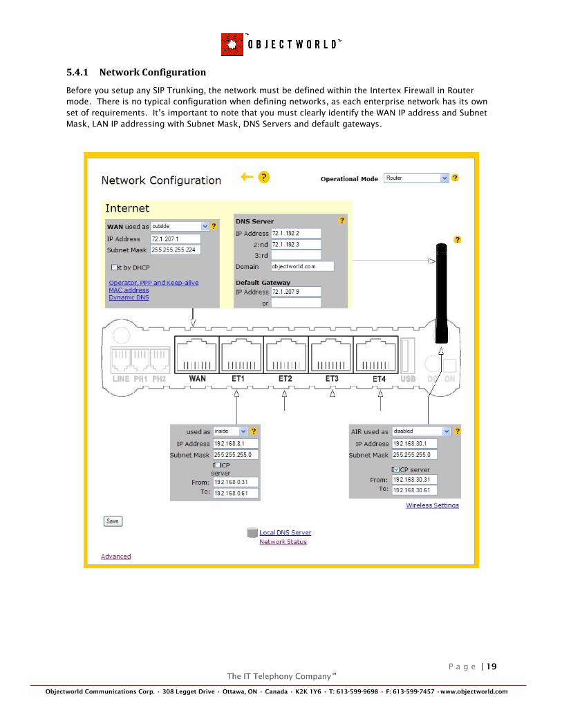
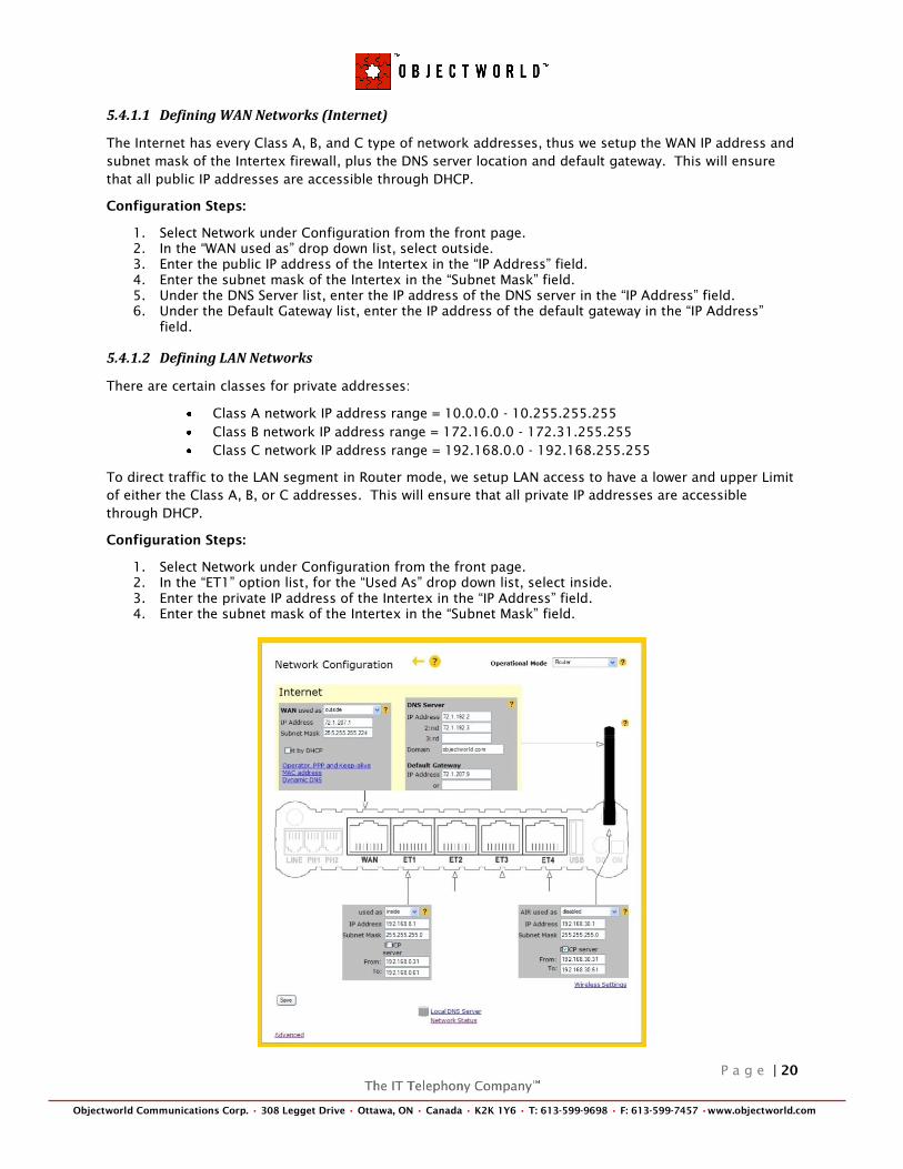
5.4.1 Network Configuration
Before you setup any SIP Trunking, the network must be defined within the Intertex Firewall in Router
mode. There is no typical configuration when defining networks, as each enterprise network has its own
set of requirements. It‘s important to note that you must clearly identify the WAN IP address and Subnet
Mask, LAN IP addressing with Subnet Mask, DNS Servers and default gateways.
P a g e | 20
Objectworld Communications Corp. • 308 Legget Drive • Ottawa, ON • Canada • K2K 1Y6 • T: 613-599-9698 • F: 613-599-7457 •www.objectworld.com
5.4.1.1 Defining WAN Networks (Internet)
The Internet has every Class A, B, and C type of network addresses, thus we setup the WAN IP address and
subnet mask of the Intertex firewall, plus the DNS server location and default gateway. This will ensure
that all public IP addresses are accessible through DHCP.
Configuration Steps:
1. Select Network under Configuration from the front page.
2. In the ―WAN used as‖ drop down list, select outside.
3. Enter the public IP address of the Intertex in the ―IP Address‖ field.
4. Enter the subnet mask of the Intertex in the ―Subnet Mask‖ field.
5. Under the DNS Server list, enter the IP address of the DNS server in the ―IP Address‖ field.
6. Under the Default Gateway list, enter the IP address of the default gateway in the ―IP Address‖
field.
5.4.1.2 Defining LAN Networks
There are certain classes for private addresses:
Class A network IP address range = 10.0.0.0 - 10.255.255.255
Class B network IP address range = 172.16.0.0 - 172.31.255.255
Class C network IP address range = 192.168.0.0 - 192.168.255.255
To direct traffic to the LAN segment in Router mode, we setup LAN access to have a lower and upper Limit
of either the Class A, B, or C addresses. This will ensure that all private IP addresses are accessible
through DHCP.
Configuration Steps:
1. Select Network under Configuration from the front page.
2. In the ―ET1‖ option list, for the ―Used As‖ drop down list, select inside.
3. Enter the private IP address of the Intertex in the ―IP Address‖ field.
4. Enter the subnet mask of the Intertex in the ―Subnet Mask‖ field.
P a g e | 21
Objectworld Communications Corp. • 308 Legget Drive • Ottawa, ON • Canada • K2K 1Y6 • T: 613-599-9698 • F: 613-599-7457 •www.objectworld.com
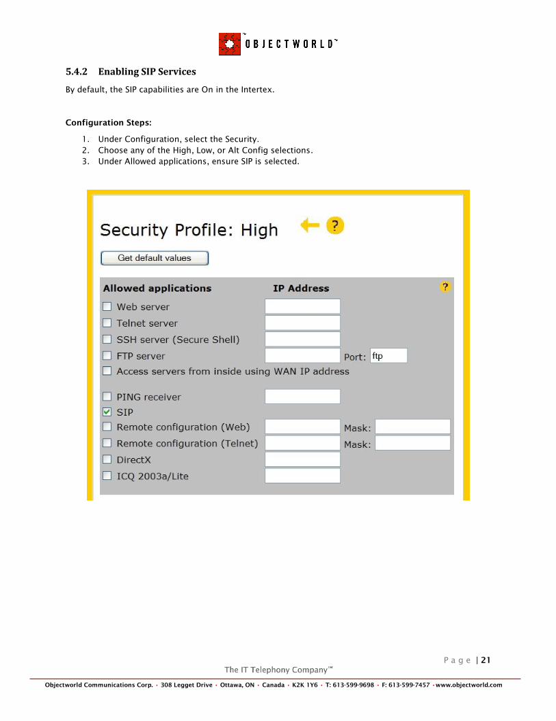
5.4.2 Enabling SIP Services
By default, the SIP capabilities are On in the Intertex.
Configuration Steps:
1. Under Configuration, select the Security.
2. Choose any of the High, Low, or Alt Config selections.
3. Under Allowed applications, ensure SIP is selected.
P a g e | 22
Objectworld Communications Corp. • 308 Legget Drive • Ottawa, ON • Canada • K2K 1Y6 • T: 613-599-9698 • F: 613-599-7457 •www.objectworld.com
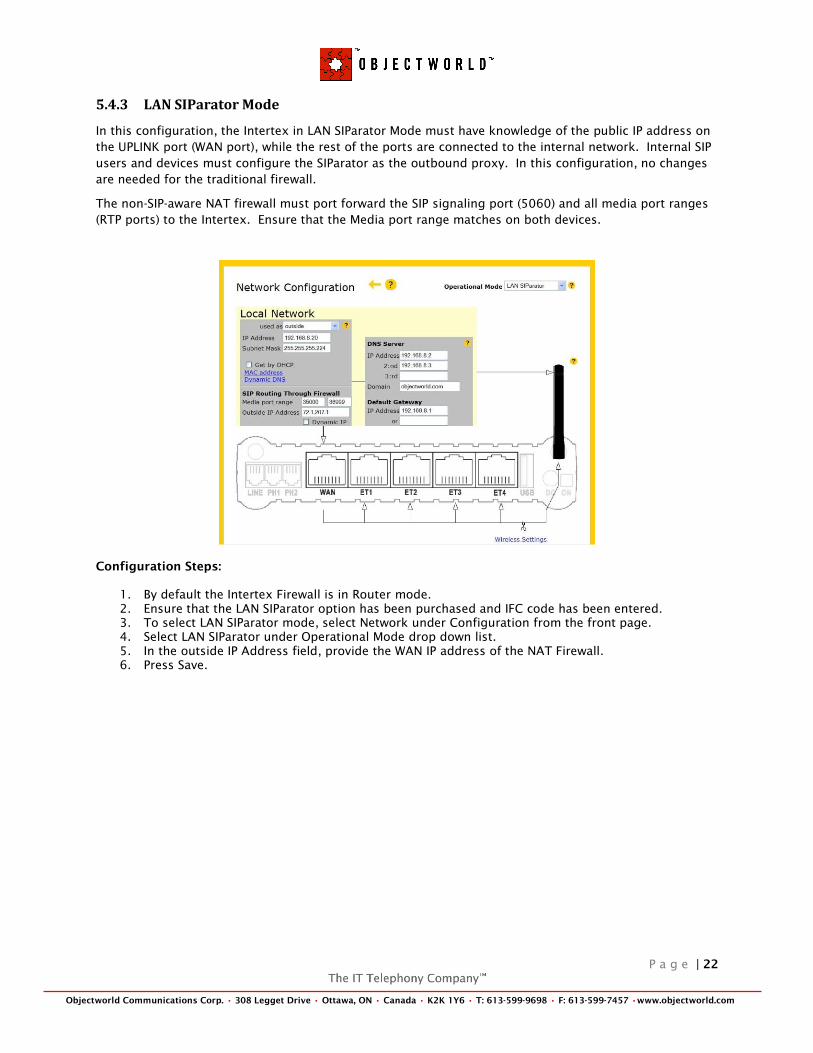
5.4.3 LAN SIParator Mode
In this configuration, the Intertex in LAN SIParator Mode must have knowledge of the public IP address on
the UPLINK port (WAN port), while the rest of the ports are connected to the internal network. Internal SIP
users and devices must configure the SIParator as the outbound proxy. In this configuration, no changes
are needed for the traditional firewall.
The non-SIP-aware NAT firewall must port forward the SIP signaling port (5060) and all media port ranges
(RTP ports) to the Intertex. Ensure that the Media port range matches on both devices.
Configuration Steps:
1. By default the Intertex Firewall is in Router mode.
2. Ensure that the LAN SIParator option has been purchased and IFC code has been entered.
3. To select LAN SIParator mode, select Network under Configuration from the front page.
4. Select LAN SIParator under Operational Mode drop down list.
5. In the outside IP Address field, provide the WAN IP address of the NAT Firewall.
6. Press Save.

P a g e | 23
Objectworld Communications Corp. • 308 Legget Drive • Ottawa, ON • Canada • K2K 1Y6 • T: 613-599-9698 • F: 613-599-7457 •www.objectworld.com
5.5 SIP Trunking with Registrations
5.5.1 What is a REGISTER?
What is a REGISTER and how does it work?
For outgoing SIP requests, only a SIP proxy is needed. Incoming SIP requests need a mechanism that
keeps track of the local users so that SIP requests can be relayed to the right machine and user. The
Registrar keeps track of the local users by mapping the SIP address (SIP URI) and the Contact IP address
contained in the REGISTER. This is particularly important when NAT is used, since no SIP Registrar on the
outside will know the IP addresses on the internal networks.
The Intertex Firewalls manage user registrations, allowing the SIP module to keep track of where to send
incoming session requests. It is also possible to make restrictions on which users are allowed to register
and/or from where they can register. You can also monitor which users are currently registered. The
integrated Registrar can be the main registrar or only be a passive registrar, monitoring and storing
information from registration done at an outside registrar. In both cases, the Registrar keeps the required
information to locate users inside the firewall. Each registration has a timeout after which it is removed
unless the client extends it.
5.5.2 How It Applies to SIP Trunking
In the SIP Trunking scenario, the Objectworld UC Server REGISTERs a SIP URI of the SIP Trunk with the
carrier/service provider. Contained in the REGISTER, is the PSTN Telephone number and Domain/IP
Address of the service provider or enterprise, which forms the SIP URI, example:
sip:[email protected] or sip:[email protected]. Also contained in the REGISTER is any
Authentication username and password.
As the REGISTER is sent from UC Server to the carrier/service provider, the Intertex Firewall monitors and
dynamically records the status of the registration for further incoming SIP Signaling between UC Server
and the carrier/service provider. The Intertex Firewall remembers the Transport Protocol used
(UDP/TCP/TLS), the internal network IP address for the Objectworld UC Server (Contact Header), and the
SIP URI that was registered. As the registration is monitored by the Intertex Firewall, any subsequent
incoming SIP signaling from the external carrier/service provider traverses to the internally located UC
Server.
It is important to note that the main Registrar within Intertex Firewall is not used. The account UserID,
Domain, Authentication Username and Password information within the Intertex main Registrar are not
used. The ―Local SIP Domains‖ (or FQDN) programmed in the User Database are different than the Domain
Name used by the Objectworld UC Server.
Instead, the Intertex is a passive registrar, monitoring and storing information from registrations done at
an outside registrar. The Intertex Firewall will perform a Domain Lookup when it sees a request for a
domain that is not its own and forwards the SIP requests/responses to UC Server.
One caveat, when UC Server REGISTERs with a specific SIP URI, but the service provider sends SIP requests
and responses to a different SIP URI, one that does not match the SIP URI in the UC Server REGISTER, then a
Static Domain Forwarding is required to ensure the service provider‘s SIP requests and responses traverse
the firewall. If this is the case follow the next section ―SIP Trunking without Registrations.‖
No configuration is required on the Intertex, as the Intertex Firewall monitors and records the registrations
between UC Server and the service provider for the purpose of routing SIP messages to the appropriate
server.
Note: In the SIP Switch configuration, ensure that ―Use as SIP Server for Domain‖ must not be the same SIP
domain as UC Server.
P a g e | 24
Objectworld Communications Corp. • 308 Legget Drive • Ottawa, ON • Canada • K2K 1Y6 • T: 613-599-9698 • F: 613-599-7457 •www.objectworld.com
5.6 SIP Trunking without Registrations
In this scenario, the carrier/service provider does not require registration and authentication. Without a
REGISTER, the Intertex Firewall does not have any means to determine the location of the Objectworld UC
Server for incoming SIP signaling. On the Intertex there is only one option to overcome this problem. It is
recommended that a static domain forwarding registration is created.
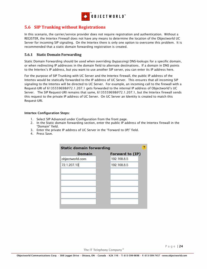
5.6.1 Static Domain Forwarding
Static Domain Forwarding should be used when overriding (bypassing) DNS-lookups for a specific domain,
or when redirecting IP addresses in the domain field to alternate destinations. If a domain in DNS points
to the Intertex‘s IP address, but you want to use another SIP server, you can enter its IP address here.
For the purpose of SIP Trunking with UC Server and the Intertex firewall, the public IP address of the
Intertex would be statically forwarded to the IP address of UC Server. This ensures that all incoming SIP
signaling to the Intertex will be directed to UC Server. For example, an incoming call to the firewall with a
Request-URI of [email protected] gets forwarded to the internal IP address of Objectworld‘s UC
Server. The SIP Request-URI remains that same, [email protected], but the Intertex firewall sends
this request to the private IP address of UC Server. On UC Server an Identity is created to match this
Request-URI.
Intertex Configuration Steps:
1. Select SIP Advanced under Configuration from the front page.
2. In the Static domain forwarding section, enter the public IP address of the Intertex firewall in the
―Domain‖ field.
3. Enter the private IP address of UC Server in the ―Forward to (IP)‖ field.
4. Press Save.
P a g e | 25
Objectworld Communications Corp. • 308 Legget Drive • Ottawa, ON • Canada • K2K 1Y6 • T: 613-599-9698 • F: 613-599-7457 •www.objectworld.com
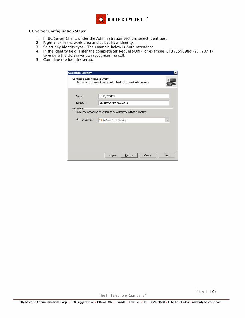
UC Server Configuration Steps:
1. In UC Server Client, under the Administration section, select Identities.
2. Right click in the work area and select New Identity.
3. Select any identity type. The example below is Auto Attendant.
4. In the Identity field, enter the complete SIP Request-URI (For example, [email protected])
to ensure the UC Server can recognize the call.
5. Complete the Identity setup.
P a g e | 26
Objectworld Communications Corp. • 308 Legget Drive • Ottawa, ON • Canada • K2K 1Y6 • T: 613-599-9698 • F: 613-599-7457 •www.objectworld.com
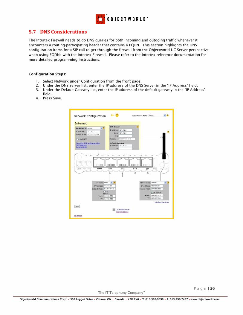
5.7 DNS Considerations
The Intertex Firewall needs to do DNS queries for both incoming and outgoing traffic whenever it
encounters a routing-participating header that contains a FQDN. This section highlights the DNS
configuration items for a SIP call to get through the firewall from the Objectworld UC Server perspective
when using FQDNs with the Intertex Firewall. Please refer to the Intertex reference documentation for
more detailed programming instructions.
Configuration Steps:
1. Select Network under Configuration from the front page.
2. Under the DNS Server list, enter the IP address of the DNS Server in the ―IP Address‖ field.
3. Under the Default Gateway list, enter the IP address of the default gateway in the ―IP Address‖
field.
4. Press Save.
P a g e | 27
Objectworld Communications Corp. • 308 Legget Drive • Ottawa, ON • Canada • K2K 1Y6 • T: 613-599-9698 • F: 613-599-7457 •www.objectworld.com
5.7.1 Using a Public DNS
In a scenario where the Intertex must use a public DNS Server, the Intertex Firewall has a table/function to
take care of this. This configuration assumes that all DNS servers (regardless of location) in the
environment resolve domain names to the same IP addresses (for example, this is NOT a split-DNS
configuration).
The Objectworld UC Server is located on a NAT‘d network, and DNS queries for the FQDN of the
Objectworld UC Server should point to the external IP address of the Intertex Firewall. The Objectworld UC
Server on the LAN should be ―authoritative‖ for that domain name and respond to SIP requests using that
name when received. This means that the Objectworld UC Server must have a host name and a domain
name. These names should be the same as the DNS name of the external WAN port of the Intertex
Firewall.
We will use an example of the FQDN ―objectworld.com‖, where it publicly resolves to the external WAN IP
of the Intertex. If the Intertex received a request for ―objectworld.com‖, it would look it up and it would
resolve to itself. Therefore, there would be a loop. Instead, under Configuration, in the SIP Advanced
section, you can use the "Static domain forwarding" table. There, you can specify that if the Intertex gets a
request for a particular domain, it won't look it up; it will send it to the IP address and port listed in the
table. It is like a static DNS table.
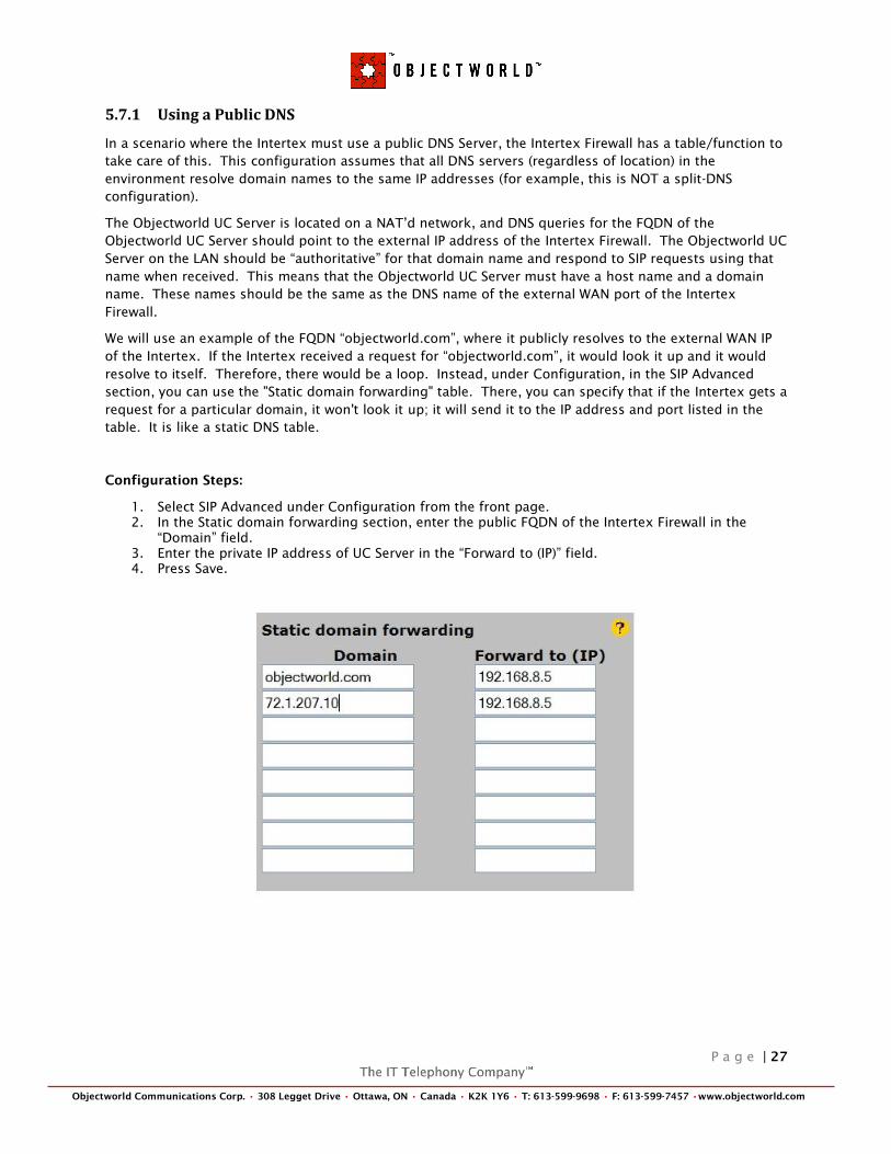
Configuration Steps:
1. Select SIP Advanced under Configuration from the front page.
2. In the Static domain forwarding section, enter the public FQDN of the Intertex Firewall in the
―Domain‖ field.
3. Enter the private IP address of UC Server in the ―Forward to (IP)‖ field.
4. Press Save.
P a g e | 28
Objectworld Communications Corp. • 308 Legget Drive • Ottawa, ON • Canada • K2K 1Y6 • T: 613-599-9698 • F: 613-599-7457 •www.objectworld.com
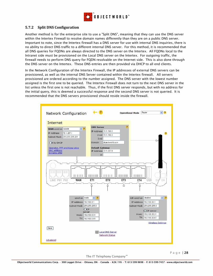
5.7.2 Split DNS Configuration
Another method is for the enterprise site to use a "Split DNS", meaning that they can use the DNS server
within the Intertex Firewall to resolve domain names differently than they are on a public DNS server.
Important to note, since the Intertex firewall has a DNS server for use with internal DNS inquiries, there is
no ability to direct DNS traffic to a different internal DNS server. For this method, it is recommended that
all DNS queries for FQDNs are always directed to the DNS server on the Intertex. All FQDNs local to the
Intranet side must be provisioned on the Local DNS server on the Intertex. For outgoing traffic, the
firewall needs to perform DNS query for FQDN resolvable on the Internet side. This is also done through
the DNS server on the Intertex. These DNS entries are then provided via DHCP to all end clients.
In the Network Configuration of the Intertex Firewall, the IP addresses of external DNS servers can be
provisioned, as well as the internal DNS Server contained within the Intertex firewall. All servers
provisioned are ordered according to the number assigned. The DNS server with the lowest number
assigned is the first one to be queried. The Intertex Firewall does not turn to the next DNS server in the
list unless the first one is not reachable. Thus, if the first DNS server responds, but with no address for
the initial query, this is deemed a successful response and the second DNS server is not queried. It is
recommended that the DNS servers provisioned should reside inside the firewall.

P a g e | 29
Objectworld Communications Corp. • 308 Legget Drive • Ottawa, ON • Canada • K2K 1Y6 • T: 613-599-9698 • F: 613-599-7457 •www.objectworld.com
6 TROUBLESHOOTING
6.1 Intertex Tools
The Intertex Firewalls have excellent troubleshooting tools. Included in the Intertex Firewall are Log
Viewers, and Syslog Server capabilities.
6.1.1 Log Settings
The Intertex Firewall log viewer is an easy way to see Firewall related messages, such as denial of services
issues. The SIP Log Viewer is a good way to see SIP protocol related messages. These logs are a good way
to see the SIP signaling between UC Server and the service provider. These logs can quickly show the
messages between devices. The logs will show the SIP traffic on all interfaces/ports of the Intertex
Firewall. Also, when SIP Debug Messages are turned On, the Intertex will give more detailed information
as to why there are errors in certain messages or what actions it took given the information it has.
Firewall Log Settings
SIP Logs Settings
P a g e | 30
Objectworld Communications Corp. • 308 Legget Drive • Ottawa, ON • Canada • K2K 1Y6 • T: 613-599-9698 • F: 613-599-7457 •www.objectworld.com
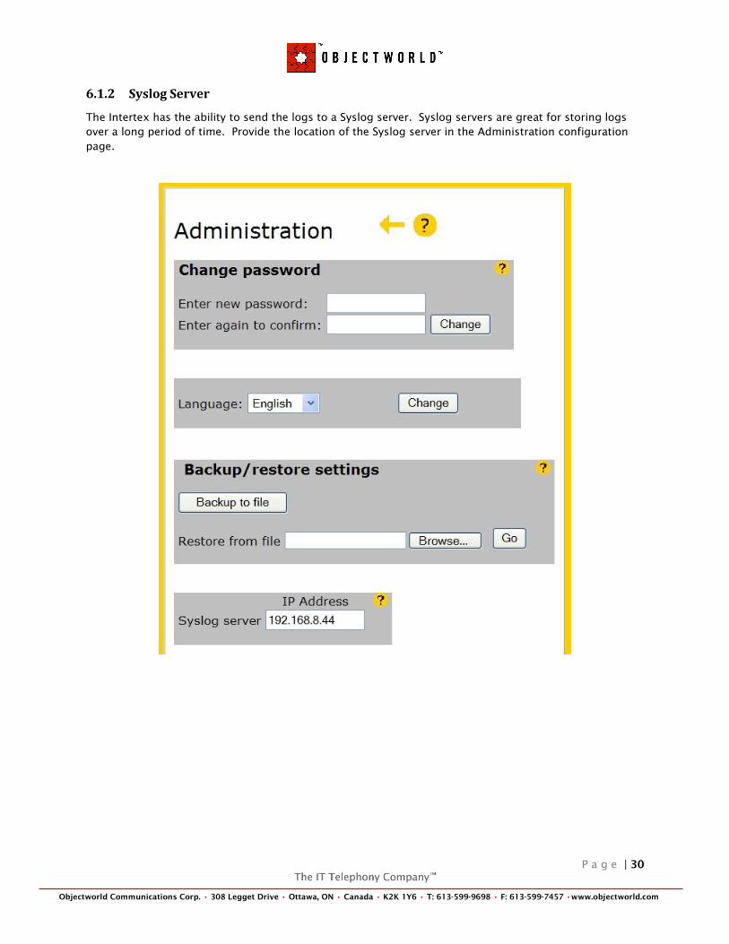
6.1.2 Syslog Server
The Intertex has the ability to send the logs to a Syslog server. Syslog servers are great for storing logs
over a long period of time. Provide the location of the Syslog server in the Administration configuration
page.

P a g e | 31
Objectworld Communications Corp. • 308 Legget Drive • Ottawa, ON • Canada • K2K 1Y6 • T: 613-599-9698 • F: 613-599-7457 •www.objectworld.com
7 GLOSSARY
ALG Application Layer Gateway (also known as Application-Level Gateway) consists of a
security component that augments a firewall or NAT employed in a computer network. It
allows legitimate application data to pass through the security checks of the firewall that
would have otherwise restricted the traffic for not meeting its limited filter criteria.
Carrier A telephone company (or telco) provides telecommunications services such as telephony
and data communications.
DNS The domain name system (DNS) stores and associates many types of information with
domain names, but most importantly, it translates domain names (computer host names)
to IP addresses.
Domain A group of networked computers that share a common communications address.
Enterprise A company organized for commercial purposes; a business firm.
ENUM TElephone NUmber Mapping is a suite of protocols to unify the telephone numbering
system E.164 with the Internet addressing system DNS by using an indirect lookup
method, to obtain NAPTR records. The records are stored in a DNS database.
FQDN An unambiguous domain name that specifies the node's position in the DNS tree
hierarchy absolutely. To distinguish a FQDN from a regular domain name, a trailing
period is added, for example, somehost.example.com. A FQDN differs from a regular
domain name by its absoluteness; a suffix will not be added.
IP Address A unique address that devices use in order to identify and communicate with each other
on a computer network utilizing the Internet Protocol (IP) standard— in simpler terms, a
computer address.
ISP An Internet Service Provider (also called Internet Access Provider) is a business or
organization that provides consumers with access to the Internet and related services.
ITSP An Internet Telephony Service Provider offers an Internet data service for making
telephone calls using VoIP (Voice over IP) technology.
LAN A local area network is a computer network covering a small geographic area, such as a
home, office, or a group of buildings.
Proxy A proxy server is a computer that offers a computer network service to allow clients to
make indirect network connections to other network services.
PSTN The public switched telephone network is the network of the world's public circuit-
switched telephone networks, in much the same way that the Internet is the network of
the world's public IP-based packet-switched networks. Originally a network of fixed-line
analog telephone systems, the PSTN is now almost entirely digital, and includes mobile as
well as fixed telephones.
Port A software port is a virtual data connection that can be used by programs to exchange
data directly, instead of going through a file or other temporary storage location. The
most common of these are TCP and UDP ports which are used to exchange data between
computers on the Internet.
NAT The process of Network Address Translation (also known as network masquerading,
native address translation or IP-masquerading) involves re-writing the source and/or
destination addresses of IP packets as they pass through a router or firewall.
P a g e | 32
Objectworld Communications Corp. • 308 Legget Drive • Ottawa, ON • Canada • K2K 1Y6 • T: 613-599-9698 • F: 613-599-7457 •www.objectworld.com
RTP Real-time Transport Protocol defines a standardized packet format for delivering audio
and video over the Internet.
Service Provider See ISP, ITSP, or Carrier.
SIP Session Initiation Protocol is an application-layer control (signaling) protocol for creating,
modifying, and terminating sessions with one or more participants. These sessions
include Internet telephone calls, multimedia distribution, and multimedia conferences.
SIP Trunking SIP Trunking is the mechanism used to interconnect SIP enabled PBX's and/or SIP User
Agents to each other to establish voice sessions between each other over an IP network.
Utilizing the now universal SIP standard for signaling, SIP Trunking has emerged as a
viable alternative to legacy (TDM) and fixed-line circuits for the establishment and
transmission of voice communications.
SRTP The Secure Real-time Transport Protocol (or SRTP) defines a profile of RTP (Real-time
Transport Protocol), intended to provide encryption, message authentication and integrity,
and replay protection to the RTP data in both unicast and multicast applications.
Syslog A standard for forwarding log messages in an IP network. The term "syslog" is often used
for both the actual syslog protocol, as well as the application or library sending syslog
messages. The syslog protocol is a very simplistic protocol; the syslog sender sends a
small textual message (less than 1024 bytes) to the syslog receiver.
TCP The Transmission Control Protocol is a virtual circuit protocol that is one of the core
protocols of the Internet protocol suite, often simply referred to as TCP/IP. Using TCP,
applications on networked hosts can create connections to one another, over which they
can exchange streams of data using Stream Sockets. The protocol guarantees reliable and
in-order delivery of data from sender to receiver.
TDM Time-division multiplexing (TDM) is a type of digital or (rarely) analog multiplexing in
which two or more signals or bit streams are transferred apparently simultaneously as
sub-channels in one communication channel, but physically are taking turns on the
channel. The time domain is divided into several recurrent timeslots of fixed length, one
for each sub-channel. A sample, byte or data block of sub-channel 1 is transmitted during
timeslot 1, sub-channel 2 during timeslot 2, and so on. One TDM frame consists of one
timeslot per sub-channel. After the last sub-channel the cycle starts all over again with a
new frame, starting with the second sample, byte or data block from sub-channel 1, and
so on.
TLS Transport Layer Security and its predecessor, Secure Sockets Layer (SSL), are
cryptographic protocols which provide secure communications on the Internet for such
things as web browsing, e-mail, Internet faxing, and other data transfers.
UDP The User Datagram Protocol is one of the core protocols of the Internet protocol suite.
Using UDP, programs on networked computers can send short messages sometimes
known as datagrams (using Datagram Sockets) to one another. UDP is sometimes called
the Universal Datagram Protocol.
WAN Wide area network is a computer network that covers a broad geographical area (that is,
any network whose communications links across metropolitan, regional, or national
boundaries). Or, less formally, a network that uses routers and public communications
links.