introducing feedback control to first...
TRANSCRIPT
Session 2161
Introducing Feedback Control to First Year Engineering Students using LabVIEW
Samuel Daniels, Dave Harding, Mike Collura
School of Engineering & Applied Science University of New Haven
Abstract This paper discusses the introduction of basic feedback control concepts and applications specifically selected for first year engineering & applied science students. These activities are introduced in the second half of a first semester class that is part of a sequence of first and second year courses used to develop a strong foundation for programs in various engineering disciplines. This sequence of courses uses a Multidisciplinary Engineering Foundation Spiral1 in the form of a four-semester sequence of engineering courses, matched closely with the development of students’ mathematical sophistication and analytical capabilities and integrated with coursework in the sciences. Introduction Feedback control is one of many common multidisciplinary areas covered by the new curriculum where engineering topics are presented in the spiral from five key areas or pillars: electrical circuits, thermodynamics/fluid mechanics, material balances, structural mechanics and systems. Unlike the traditional approach, each of the foundation courses includes a mix of these topics, presented in a variety of disciplinary contexts. A solid background is developed by touching key concepts at several points along the spiral in different courses, adding depth and sophistication at each pass. Each foundation course also stresses the development of several essential skills, such as problem-solving, oral and written communication, the design process, teamwork, project management, computer analysis methods, laboratory investigation, data analysis and model development. In addition to providing a broad engineering background, this sequence of multidisciplinary courses develops the foundation for building substantial depth in key areas of importance for engineering students. The first semester freshman course that includes feedback control is EAS 109, “Project Planning and Development” (2 semester credits). This course focuses on the development of project management skills using project-based activities to excite and motivate freshman. This paper will present the feedback control projects tied to the development of good project development skills, and provide a review of the concepts introduced including proportional, integral & differential control. The course is broken down into two major projects during the semester. A
“Proceedings of the 2005 American Society for Engineering Education Annual Conference & Exposition Copyright © 2005, American Society for Engineering Education”
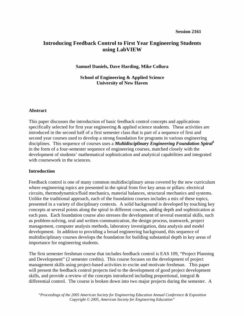
manufacturing floor simulation involving the entire class2 and smaller group-based controls projects that use classical control experiments: solar tracking, water level control, salinity control, temperature control of a chamber. For the control experiments, the system behavior is observed rather than modeled and the control is performed with National Instruments equipment and LabVIEW graphical programming language. Students first develop a basic level of competency in the LabVIEW g-code, and then use simple programming techniques to develop an application-oriented understanding of feedback control. Control is an integral part of many engineering and applied science majors in the school of engineering and applied science at the University of New Haven. Each major has specific control courses that emphasize different aspects relevant to their individual disciplines. Some require specialized control courses (chemical, electrical & computer engineering) while other majors have special topics within courses or electives that emphasize control of engineering systems. The typical approach to teaching controls involves the system modeling approach prior to hands-on applications, if any. Typical prerequisites include differential equations and a system modeling & analysis course in one of the primary areas: thermo-fluids, mechanics, and electrical circuits. While the literature provides a great many examples of applied feedback control experience used to enhance the standard system analysis & design of a control system, the exposure to control issues without the prerequisite system modeling are less common. For example, the multidisciplinary freshman course sequence at the University of Notre Dame introduces control concepts using an acid neutralization reactor.3 In the spiral curriculum approach to teaching controls as a component of the systems pillar, we reduce the classic Bloom’s taxonomy4 approach to three categories E.A.S. (explore, analyze, synthesize). For example, Bloom’s first three categories (knowledge, comprehension & application) are combined into explore with the other categories similarly combined. The controls content of EAS109 serves the explore stage of student development while the first semester sophomore course, modeled after the conservation principles course at Rose-Hulman5, teaches students to model (analyze) general system problems. The second semester thermo-fluids, structures and circuits courses, taught concurrently with differential equations, provide a more detailed system modeling approach. Later, discipline specific courses will focus on applications of the system modeling and control in a traditional manner. It is our hope that the systematic development of control principles and applications will enhance the upper level classes and allow for a significantly improvement in student understanding and capabilities. LabVIEW Graphical Programming National Instruments LabVIEW provides an easy to understand graphical environment for teaching basic feedback control without the obligatory system modeling and analysis. For freshman, the intent is to provide an extremely motivational hands-on experience with feedback control as a first layer of the spiral curriculum. Basic open and closed loop control is easily accomplished with a standard “while” loop in LabVIEW and a “shift register” which carries values from one iteration step to the next. Figure 1 shows a sample proportional control loop. A sensor is read from an analog input subroutine or VI(virtual instrument) is then compared to a set point value. The difference is
“Proceedings of the 2005 American Society for Engineering Education Annual Conference & Exposition Copyright © 2005, American Society for Engineering Education”
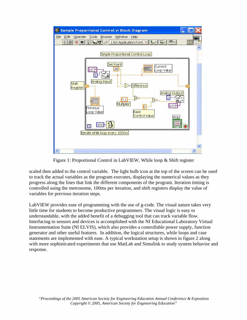
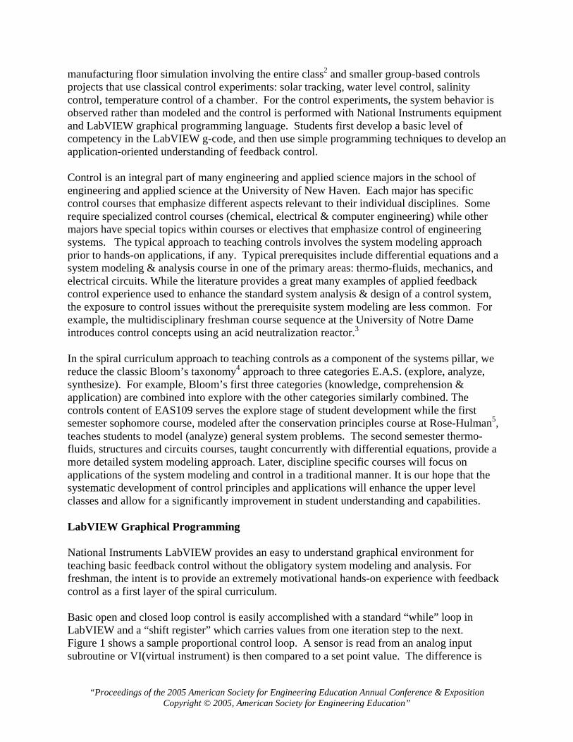
Figure 1: Proportional Control in LabVIEW, While loop & Shift register scaled then added to the control variable. The light bulb icon at the top of the screen can be used to track the actual variables as the program executes, displaying the numerical values as they progress along the lines that link the different components of the program. Iteration timing is controlled using the metronome, 100ms per iteration, and shift registers display the value of variables for previous iteration steps. LabVIEW provides ease of programming with the use of g-code. The visual nature takes very little time for students to become productive programmers. The visual logic is easy to understandable, with the added benefit of a debugging tool that can track variable flow. Interfacing to sensors and devices is accomplished with the NI Educational Laboratory Virtual Instrumentation Suite (NI ELVIS), which also provides a controllable power supply, function generator and other useful features. In addition, the logical structures, while loops and case statements are implemented with ease. A typical workstation setup is shown in figure 2 along with more sophisticated experiments that use MatLab and Simulink to study system behavior and response.
“Proceedings of the 2005 American Society for Engineering Education Annual Conference & Exposition Copyright © 2005, American Society for Engineering Education”
Figure 2: NI ELVIS Station & Quanser Solar Tracking System
Building to PID control via LabVIEW programming The challenge of taking freshman first semester students from no previous exposure to controls to the application of feedback control is actually quite straightforward. Students have an intuitive understanding of system behavior and response; and have an enormous enthusiasm for interesting challenges. The approach used can be broken down into a few simple steps. First, use the DAQ (data acquisition) interface to acquire simple measurements, showing the ease of interfacing to external devices with NI ELVIS & LabVIEW. Using the virtual instruments available with the NI ELVIS system, digital multi-meter and oscilloscope, provide an obvious starting point. Building a simple program to collect and chart data illustrates the wiring needed to interface to the analog input channels using the breadboard and wiring of the analog output to the NI ELVIS DMM illustrates computer control of analog voltage output. At this point, the students are familiar with the physical interface and the basic capabilities of LabVIEW. At this point, the basic concepts of feedback control are introduced. Students calibrate a simple thermistor in a voltage dividing circuit and develop a mathematical model of the behavior. The thermistor circuit and LabVIEW program are used to develop a digital thermometer for later use with the thermal chamber project. The students also setup an optical encoder using an emitter, receiver and encoding wheel. With the encoder wheel tied to the same DC motors used in the manufacturing and robotics projects at the beginning of the semester, they learn how to wire the encoding system, convert the pulse signal to an RPM, and eventually use the rpm to control the voltage of the motor. At first, an open loop control program is developed to set the rpm of the motor using a voltage vs. rpm calibration curve. Then a feedback control loop is established using the RPM from the encoder, a set point for the rpm and simple proportional control shown in figure 3. Students then develop a proportional and integral controller, figure 4, adding the proportionally scaled difference in RPM to the control voltage from the previous time step. Note that the upper half of each VI controls the DC power supply.
“Proceedings of the 2005 American Society for Engineering Education Annual Conference & Exposition Copyright © 2005, American Society for Engineering Education”
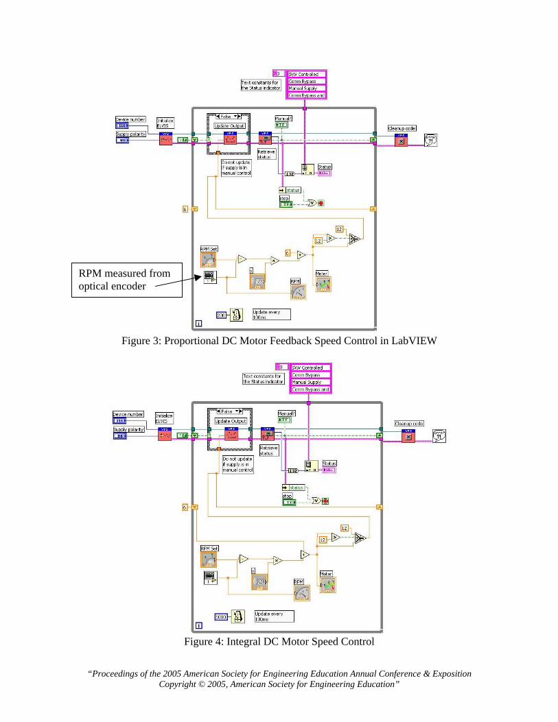
RPM measured from optical encoder
Figure 3: Proportional DC Motor Feedback Speed Control in LabVIEW
Figure 4: Integral DC Motor Speed Control
“Proceedings of the 2005 American Society for Engineering Education Annual Conference & Exposition Copyright © 2005, American Society for Engineering Education”
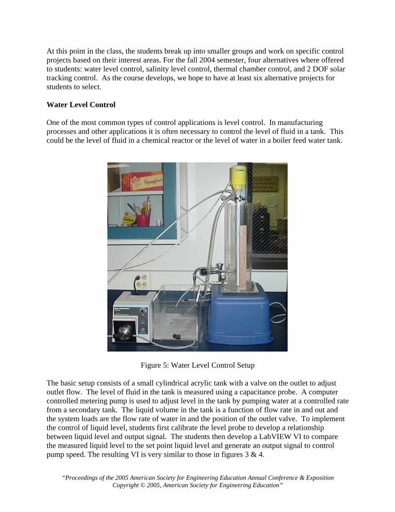
At this point in the class, the students break up into smaller groups and work on specific control projects based on their interest areas. For the fall 2004 semester, four alternatives where offered to students: water level control, salinity level control, thermal chamber control, and 2 DOF solar tracking control. As the course develops, we hope to have at least six alternative projects for students to select. Water Level Control One of the most common types of control applications is level control. In manufacturing processes and other applications it is often necessary to control the level of fluid in a tank. This could be the level of fluid in a chemical reactor or the level of water in a boiler feed water tank.
Figure 5: Water Level Control Setup The basic setup consists of a small cylindrical acrylic tank with a valve on the outlet to adjust outlet flow. The level of fluid in the tank is measured using a capacitance probe. A computer controlled metering pump is used to adjust level in the tank by pumping water at a controlled rate from a secondary tank. The liquid volume in the tank is a function of flow rate in and out and the system loads are the flow rate of water in and the position of the outlet valve. To implement the control of liquid level, students first calibrate the level probe to develop a relationship between liquid level and output signal. The students then develop a LabVIEW VI to compare the measured liquid level to the set point liquid level and generate an output signal to control pump speed. The resulting VI is very similar to those in figures 3 & 4.
“Proceedings of the 2005 American Society for Engineering Education Annual Conference & Exposition Copyright © 2005, American Society for Engineering Education”
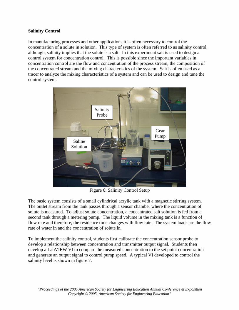
Salinity Control In manufacturing processes and other applications it is often necessary to control the concentration of a solute in solution. This type of system is often referred to as salinity control, although, salinity implies that the solute is a salt. In this experiment salt is used to design a control system for concentration control. This is possible since the important variables in concentration control are the flow and concentration of the process stream, the composition of the concentrated stream and the mixing characteristics of the system. Salt is often used as a tracer to analyze the mixing characteristics of a system and can be used to design and tune the control system.
SalinityProbe
GearPump
Saline Solution
Figure 6: Salinity Control Setup
The basic system consists of a small cylindrical acrylic tank with a magnetic stirring system. The outlet stream from the tank passes through a sensor chamber where the concentration of solute is measured. To adjust solute concentration, a concentrated salt solution is fed from a second tank through a metering pump. The liquid volume in the mixing tank is a function of flow rate and therefore, the residence time changes with flow rate. The system loads are the flow rate of water in and the concentration of solute in. To implement the salinity control, students first calibrate the concentration sensor probe to develop a relationship between concentration and transmitter output signal. Students then develop a LabVIEW VI to compare the measured concentration to the set point concentration and generate an output signal to control pump speed. A typical VI developed to control the salinity level is shown in figure 7.
“Proceedings of the 2005 American Society for Engineering Education Annual Conference & Exposition Copyright © 2005, American Society for Engineering Education”
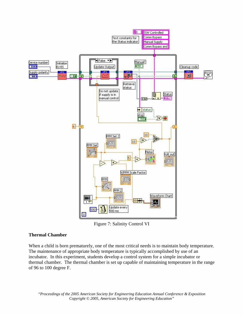
Figure 7: Salinity Control VI
Thermal Chamber When a child is born prematurely, one of the most critical needs is to maintain body temperature. The maintenance of appropriate body temperature is typically accomplished by use of an incubator. In this experiment, students develop a control system for a simple incubator or thermal chamber. The thermal chamber is set up capable of maintaining temperature in the range of 96 to 100 degree F.
“Proceedings of the 2005 American Society for Engineering Education Annual Conference & Exposition Copyright © 2005, American Society for Engineering Education”
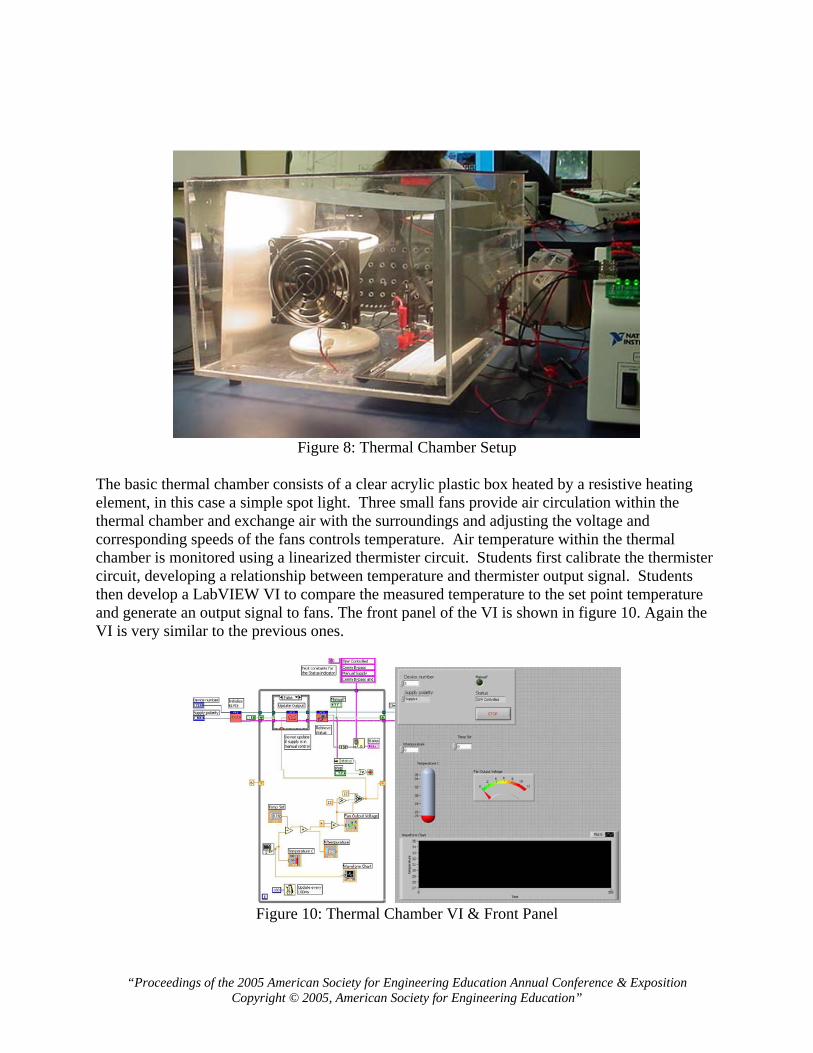
Figure 8: Thermal Chamber Setup
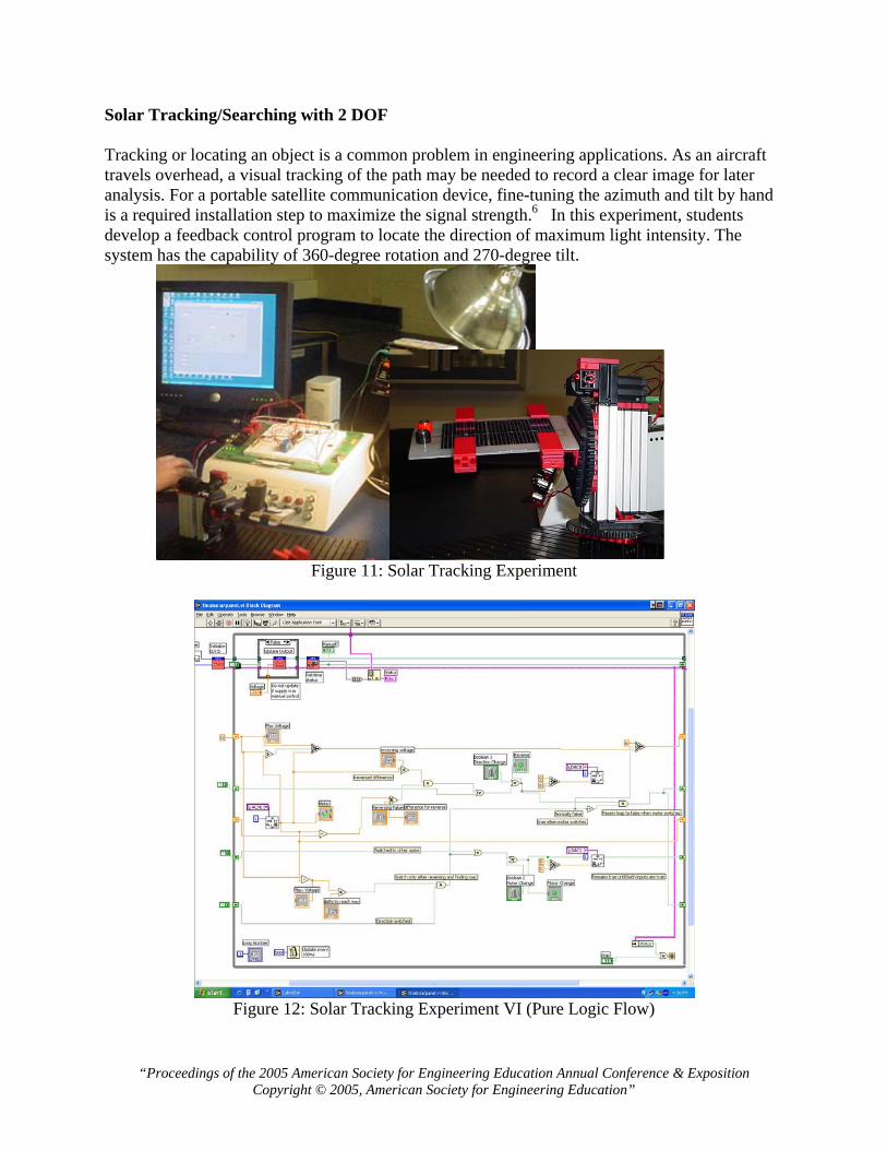
The basic thermal chamber consists of a clear acrylic plastic box heated by a resistive heating element, in this case a simple spot light. Three small fans provide air circulation within the thermal chamber and exchange air with the surroundings and adjusting the voltage and corresponding speeds of the fans controls temperature. Air temperature within the thermal chamber is monitored using a linearized thermister circuit. Students first calibrate the thermister circuit, developing a relationship between temperature and thermister output signal. Students then develop a LabVIEW VI to compare the measured temperature to the set point temperature and generate an output signal to fans. The front panel of the VI is shown in figure 10. Again the VI is very similar to the previous ones.
Figure 10: Thermal Chamber VI & Front Panel
“Proceedings of the 2005 American Society for Engineering Education Annual Conference & Exposition Copyright © 2005, American Society for Engineering Education”
Solar Tracking/Searching with 2 DOF Tracking or locating an object is a common problem in engineering applications. As an aircraft travels overhead, a visual tracking of the path may be needed to record a clear image for later analysis. For a portable satellite communication device, fine-tuning the azimuth and tilt by hand is a required installation step to maximize the signal strength.6 In this experiment, students develop a feedback control program to locate the direction of maximum light intensity. The system has the capability of 360-degree rotation and 270-degree tilt.
Figure 11: Solar Tracking Experiment
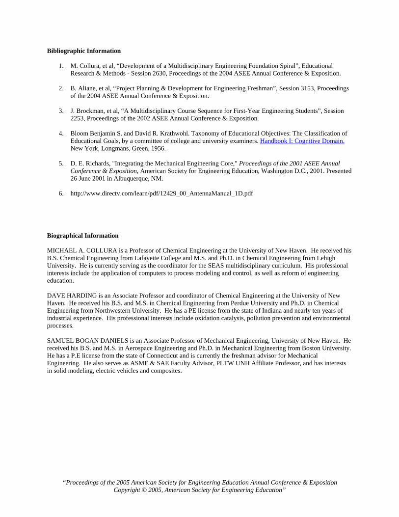
Figure 12: Solar Tracking Experiment VI (Pure Logic Flow)
“Proceedings of the 2005 American Society for Engineering Education Annual Conference & Exposition Copyright © 2005, American Society for Engineering Education”
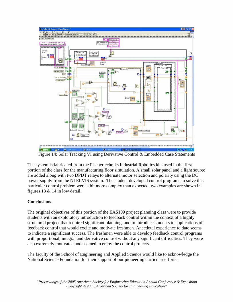
Figure 14: Solar Tracking VI using Derivative Control & Embedded Case Statements
The system is fabricated from the Fischertechniks Industrial Robotics kits used in the first portion of the class for the manufacturing floor simulation. A small solar panel and a light source are added along with two DPDT relays to alternate motor selection and polarity using the DC power supply from the NI ELVIS system. The student developed control programs to solve this particular control problem were a bit more complex than expected, two examples are shown in figures 13 & 14 in low detail. Conclusions The original objectives of this portion of the EAS109 project planning class were to provide students with an exploratory introduction to feedback control within the context of a highly structured project that required significant planning, and to introduce students to applications of feedback control that would excite and motivate freshmen. Anecdotal experience to date seems to indicate a significant success. The freshmen were able to develop feedback control programs with proportional, integral and derivative control without any significant difficulties. They were also extremely motivated and seemed to enjoy the control projects. The faculty of the School of Engineering and Applied Science would like to acknowledge the National Science Foundation for their support of our pioneering curricular efforts.
“Proceedings of the 2005 American Society for Engineering Education Annual Conference & Exposition Copyright © 2005, American Society for Engineering Education”
Bibliographic Information
1. M. Collura, et al, “Development of a Multidisciplinary Engineering Foundation Spiral”, Educational Research & Methods - Session 2630, Proceedings of the 2004 ASEE Annual Conference & Exposition.
2. B. Aliane, et al, “Project Planning & Development for Engineering Freshman”, Session 3153, Proceedings
of the 2004 ASEE Annual Conference & Exposition.
3. J. Brockman, et al, “A Multidisciplinary Course Sequence for First-Year Engineering Students”, Session 2253, Proceedings of the 2002 ASEE Annual Conference & Exposition.
4. Bloom Benjamin S. and David R. Krathwohl. Taxonomy of Educational Objectives: The Classification of
Educational Goals, by a committee of college and university examiners. Handbook I: Cognitive Domain. New York, Longmans, Green, 1956.
5. D. E. Richards, "Integrating the Mechanical Engineering Core," Proceedings of the 2001 ASEE Annual
Conference & Exposition, American Society for Engineering Education, Washington D.C., 2001. Presented 26 June 2001 in Albuquerque, NM.
6. http://www.directv.com/learn/pdf/12429_00_AntennaManual_1D.pdf
Biographical Information MICHAEL A. COLLURA is a Professor of Chemical Engineering at the University of New Haven. He received his B.S. Chemical Engineering from Lafayette College and M.S. and Ph.D. in Chemical Engineering from Lehigh University. He is currently serving as the coordinator for the SEAS multidisciplinary curriculum. His professional interests include the application of computers to process modeling and control, as well as reform of engineering education. DAVE HARDING is an Associate Professor and coordinator of Chemical Engineering at the University of New Haven. He received his B.S. and M.S. in Chemical Engineering from Perdue University and Ph.D. in Chemical Engineering from Northwestern University. He has a PE license from the state of Indiana and nearly ten years of industrial experience. His professional interests include oxidation catalysis, pollution prevention and environmental processes. SAMUEL BOGAN DANIELS is an Associate Professor of Mechanical Engineering, University of New Haven. He received his B.S. and M.S. in Aerospace Engineering and Ph.D. in Mechanical Engineering from Boston University. He has a P.E license from the state of Connecticut and is currently the freshman advisor for Mechanical Engineering. He also serves as ASME & SAE Faculty Advisor, PLTW UNH Affiliate Professor, and has interests in solid modeling, electric vehicles and composites.
“Proceedings of the 2005 American Society for Engineering Education Annual Conference & Exposition Copyright © 2005, American Society for Engineering Education”