introduction 1-1 chapter 1: computer networks and the internet 1.1 what is the internet? 1.2 network...
TRANSCRIPT
Introduction 1-1
Chapter 1: Computer networks and the Internet
1.1 What is the Internet?1.2 Network edge
end systems, access networks, links
1.3 Network core circuit switching, packet switching, network structure
1.4 Network performance evaluationDelay, loss and throughput in packet-switched networks
1.5 Protocol layers, service models1.6 Networks under attack: security1.7 History
Introduction 1-2
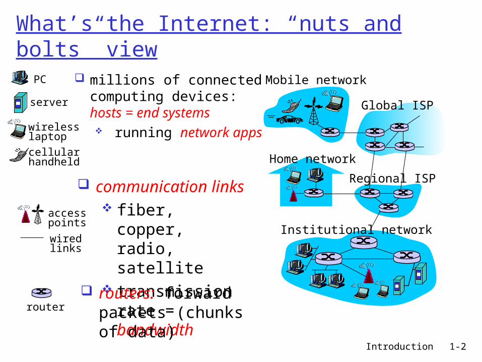
What’s the Internet: “nuts and bolts” view
millions of connected computing devices: hosts = end systems running network
apps Home network
Institutional network
Mobile network
Global ISP
Regional ISP
router
PC
server
wirelesslaptop
cellular handheld
wiredlinks
access points
communication links fiber, copper,
radio, satellite transmission
rate = bandwidth
routers: forward packets (chunks of data)
Introduction 1-3
Packet switching versus circuit switching
great for bursty data resource sharing simpler, no call setup
excessive congestion: packet delay and loss protocols needed for reliable data transfer,
congestion control Q: How to provide circuit-like behavior?
bandwidth guarantees needed for audio/video apps
still an unsolved problem (chapter 7)
Is packet switching a “slam dunk winner?”
Q: human analogies of reserved resources (circuit switching) versus on-demand allocation (packet-switching)?
Introduction 1-4
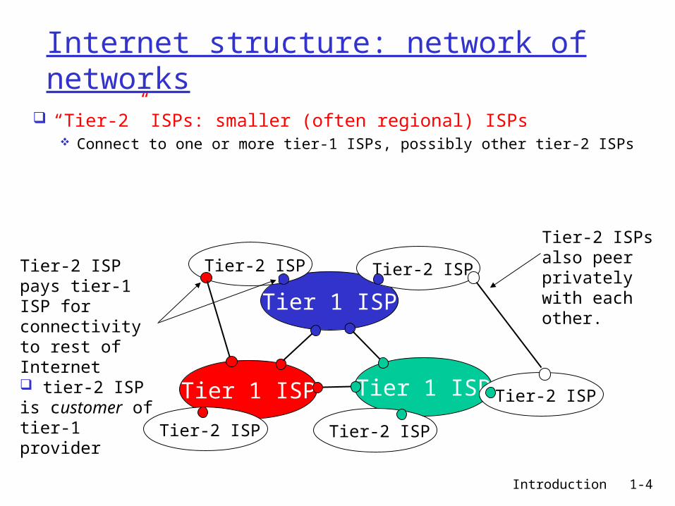
Internet structure: network of networks
“ Tier-2” ISPs: smaller (often regional) ISPs Connect to one or more tier-1 ISPs, possibly other tier-2 ISPs
Tier 1 ISP
Tier 1 ISP
Tier 1 ISP
Tier-2 ISPTier-2 ISP
Tier-2 ISP Tier-2 ISP
Tier-2 ISP
Tier-2 ISP pays tier-1 ISP for connectivity to rest of Internet tier-2 ISP is customer oftier-1 provider
Tier-2 ISPs also peer privately with each other.

Introduction 1-5
Internet structure: network of networks
“ Tier-3” ISPs and local ISPs last hop (“access”) network (closest to end systems)
Tier 1 ISP
Tier 1 ISP
Tier 1 ISP
Tier-2 ISPTier-2 ISP
Tier-2 ISP Tier-2 ISP
Tier-2 ISP
localISPlocal
ISPlocalISP
localISP
localISP Tier 3
ISP
localISP
localISP
localISP
Local and tier- 3 ISPs are customers ofhigher tier ISPsconnecting them to rest of Internet

Introduction 1-6
Internet structure: network of networks
a packet passes through many networks!
Tier 1 ISP
Tier 1 ISP
Tier 1 ISP
Tier-2 ISPTier-2 ISP
Tier-2 ISP Tier-2 ISP
Tier-2 ISP
localISPlocal
ISPlocalISP
localISP
localISP Tier 3
ISP
localISP
localISP
localISP

Introduction 1-7
How do loss and delay occur?packets queue in router buffers packet arrival rate to link exceeds output link
capacity packets queue, wait for turn
A
B
packet being transmitted (delay)
packets queueing (delay)
free (available) buffers: arriving packets dropped (loss) if no free buffers

Introduction 1-8
Delay in packet-switched networks3. Transmission delay: R=link bandwidth
(bps) L=packet length (bits) time to send bits into
link = L/R
4. Propagation delay: d = length of physical
link s = propagation speed in
medium (~2x10⁸ m/sec) propagation delay = d/s
A
B
propagation
transmission
nodalprocessing queueing
Note: s and R are very different quantities!

Introduction 1-9
Nodal delay
dproc = processing delay typically a few microsecs or less
dqueue = queuing delay depends on congestion
dtrans = transmission delay = L/R, significant for low-speed links
dprop = propagation delay a few microsecs to hundreds of msecs
proptransqueueprocnodal ddddd

Introduction 1-10
Queueing delay (revisited)
R=link bandwidth (bps) L=packet length (bits) a=average packet
arrival rate
traffic intensity = La/R
La/R ~ 0: average queueing delay small La/R -> 1: delays become large La/R > 1: more “work” arriving than can
be serviced, average delay infinite!

Introduction 1-11
Packet loss
queue (aka buffer) preceding link in buffer has finite capacity
packet arriving to full queue dropped (aka lost)
lost packet may be retransmitted by previous node, by source end system, or not at allA
B
packet being transmitted
packet arriving tofull buffer is lost
buffer (waiting area)

Introduction 1-12
Throughput
throughput: rate (bits/time unit) at which bits transferred between sender/receiver instantaneous: rate at given point in time average: rate over longer period of time
server, withfile of F bits
to send to client
link capacity
Rs bits/sec
link capacity
Rc bits/sec pipe that can carry
fluid at rate
Rs bits/sec)
pipe that can carryfluid at rate
Rc bits/sec)
server sends bits
(fluid) into pipe

Introduction 1-13
Throughput (more)
Rs < Rc What is average end-end throughput?
Rs bits/sec Rc bits/sec
Rs > Rc What is average end-end throughput?
Rs bits/sec Rc bits/sec
link on end-end path that constrains end-end throughput
bottleneck link

Introduction 1-14
Why layering?
Dealing with complex systems: explicit structure allows identification,
relationship of complex system’s pieces layered reference model for discussion
modularization eases maintenance, updating of system change of implementation of layer’s service
transparent to rest of system e.g., change in gate procedure doesn’t
affect rest of system layering considered harmful?

Introduction 1-15
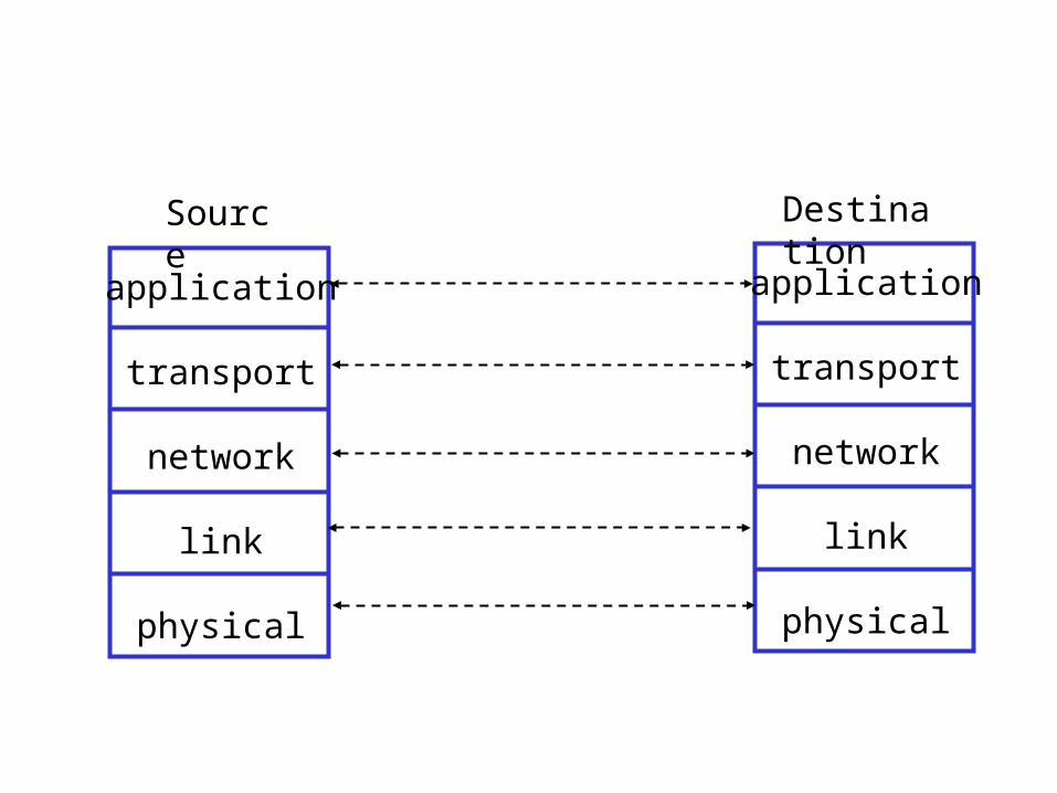
Internet protocol stack application: supporting network
applications FTP, SMTP, HTTP
transport: process-process data transfer TCP, UDP
network: routing of datagrams from source to destination IP, routing protocols
link: data transfer between neighboring network elements PPP, Ethernet
physical: bits “on the wire”
application
transport
network
link
physical

Introduction 1-16
ISO/OSI reference model presentation: allow applications
to interpret meaning of data, e.g., encryption, compression, machine-specific conventions
session: synchronization, checkpointing, recovery of data exchange
Internet stack “missing” these layers! these services, if needed, must
be implemented in application needed?
application
presentation
session
transport
network
link
physical
application
transport
network
link
physical
application
transport
network
link
physical
Source Destination

Introduction 1-18
sourceapplicatio
ntransportnetwork
linkphysical
HtHn M
segment Ht
datagram
destination
application
transportnetwork
linkphysical
HtHnHl M
HtHn M
Ht M
M
networklink
physical
linkphysical
HtHnHl M
HtHn M
HtHn M
HtHnHl M
router
switch
Encapsulationmessage M
Ht M
Hn
frame

5: DataLink Layer 5-19
A day in the life: scenario
Comcast network 68.80.0.0/13
Google’s network 64.233.160.0/19 64.233.169.105
web server
DNS server
school network 68.80.2.0/24
browser
web page
5: DataLink Layer 5-20
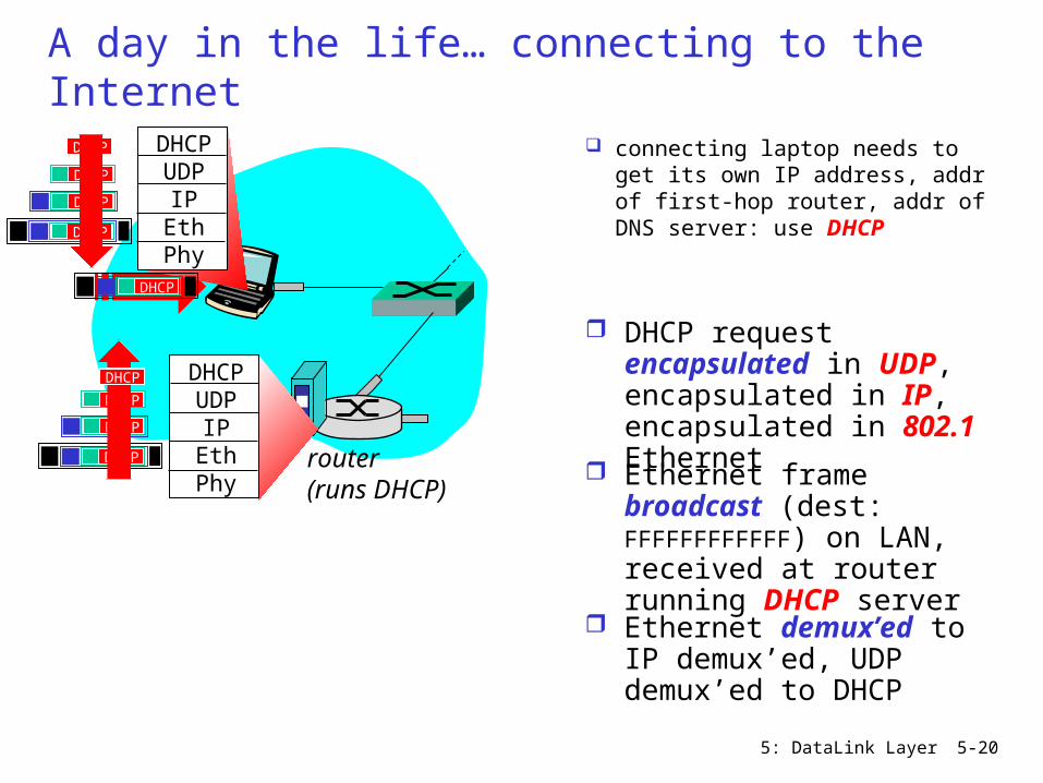
A day in the life… connecting to the Internet
connecting laptop needs to get its own IP address, addr of first-hop router, addr of DNS server: use DHCP
router(runs DHCP)
DHCPUDP
IPEthPhy
DHCP
DHCP
DHCP
DHCP
DHCP
DHCPUDP
IPEthPhy
DHCP
DHCP
DHCP
DHCPDHCP
DHCP request encapsulated in UDP, encapsulated in IP, encapsulated in 802.1 Ethernet Ethernet frame broadcast (dest: FFFFFFFFFFFF) on LAN, received at router running DHCP server
Ethernet demux’ed to IP demux’ed, UDP demux’ed to DHCP
5: DataLink Layer 5-21
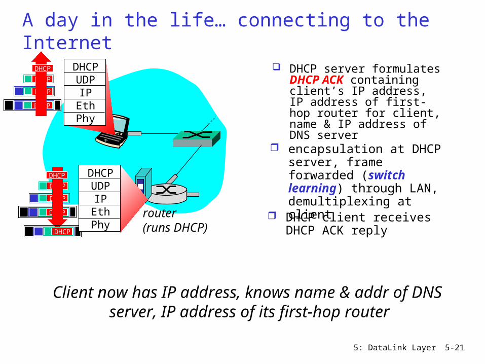
A day in the life… connecting to the Internet
DHCP server formulates DHCP ACK containing client’s IP address, IP address of first-hop router for client, name & IP address of DNS server
router(runs DHCP)
DHCPUDP
IPEthPhy
DHCP
DHCP
DHCP
DHCP
DHCPUDP
IPEthPhy
DHCP
DHCP
DHCP
DHCP
DHCP
encapsulation at DHCP server, frame forwarded (switch learning) through LAN, demultiplexing at client
Client now has IP address, knows name & addr of DNS server, IP address of its first-hop router
DHCP client receives DHCP ACK reply
5: DataLink Layer 5-22
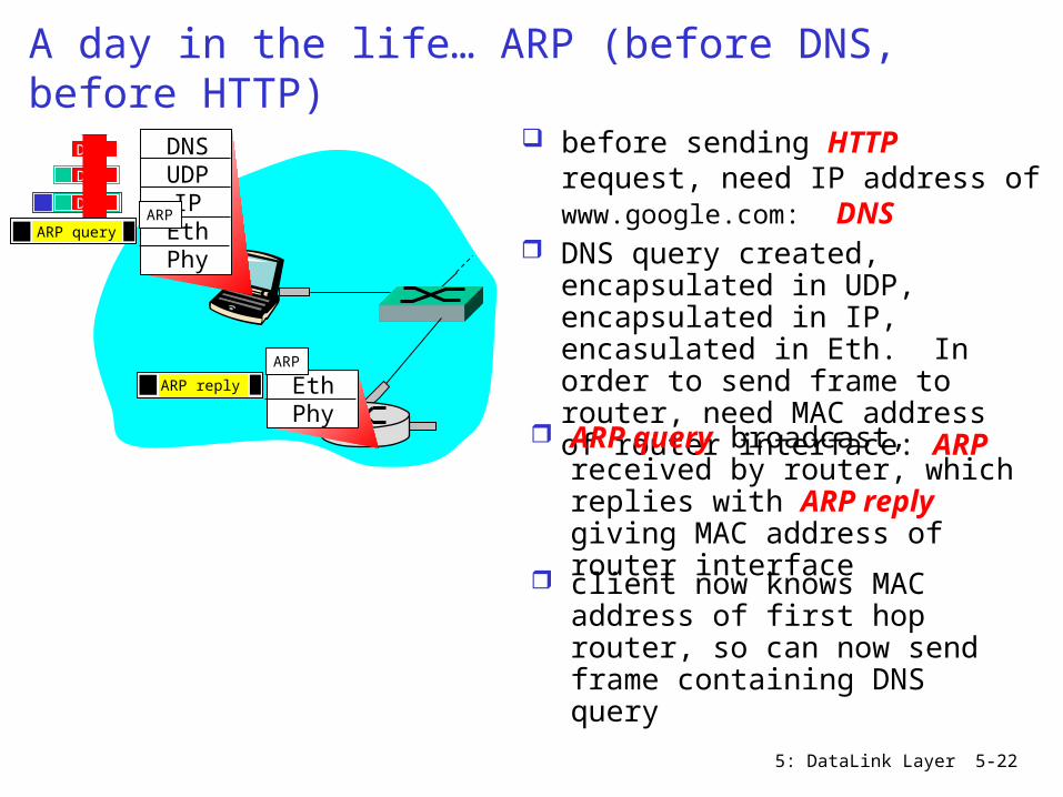
A day in the life… ARP (before DNS, before HTTP)
before sending HTTP request, need IP address of www.google.com: DNS
DNSUDP
IPEthPhy
DNS
DNS
DNS
DNS query created, encapsulated in UDP, encapsulated in IP, encasulated in Eth. In order to send frame to router, need MAC address of router interface: ARP
ARP query broadcast, received by router, which replies with ARP reply giving MAC address of router interface client now knows MAC address of first hop router, so can now send frame containing DNS query
ARP query
EthPhy
ARP
ARP
ARP reply

5: DataLink Layer 5-23
A day in the life… using DNS
DNSUDP
IPEthPhy
DNS
DNS
DNS
DNS
DNS
IP datagram containing DNS query forwarded via LAN switch from client to 1st hop router
IP datagram forwarded from campus network into comcast network, routed (tables created by RIP, OSPF, IS-IS and/or BGP routing protocols) to DNS server
demux’ed to DNS server DNS server replies to
client with IP address of www.google.com
Comcast network 68.80.0.0/13
DNS server
DNSUDP
IPEthPhy
DNS
DNS
DNS
DNS

5: DataLink Layer 5-24
A day in the life… TCP connection carrying HTTP
HTTPTCPIP
EthPhy
HTTP
to send HTTP request, client first opens TCP socket to web server
TCP SYN segment (step 1 in 3-way handshake) inter-domain routed to web server
TCP connection established!
64.233.169.105
web server
SYN
SYN
SYN
SYN
TCPIP
EthPhy
SYN
SYN
SYN
SYNACK
SYNACK
SYNACK
SYNACK
SYNACK
SYNACK
SYNACK
web server responds with TCP SYNACK (step 2 in 3-way handshake)

5: DataLink Layer 5-25
A day in the life… HTTP request/reply
HTTPTCPIP
EthPhy
HTTP
HTTP request sent into TCP socket
IP datagram containing HTTP request routed to www.google.com
IP datgram containing HTTP reply routed back to client
64.233.169.105
web server
HTTPTCPIP
EthPhy
web server responds with HTTP reply (containing web page)
HTTP
HTTP
HTTPHTTP
HTTP
HTTP
HTTP
HTTP
HTTP
HTTP
HTTP
HTTP
HTTP
web page finally (!!!) displayed

5: DataLink Layer 5-26
Addressing: routing to another LAN
R
1A-23-F9-CD-06-9B
222.222.222.220111.111.111.110
E6-E9-00-17-BB-4B
CC-49-DE-D0-AB-7D
111.111.111.112
111.111.111.111
A74-29-9C-E8-FF-55
222.222.222.221
88-B2-2F-54-1A-0F
B222.222.222.222
49-BD-D2-C7-56-2A
walkthrough: send datagram from A to B via R assume A knows B’s IP address
two ARP tables in router R, one for each IP network (LAN)

5: DataLink Layer 5-27
A creates IP datagram with source A, destination B A uses ARP to get R’s MAC address for 111.111.111.110 A creates link-layer frame with R's MAC address as dest,
frame contains A-to-B IP datagram A’s NIC sends frame R’s NIC receives frame R removes IP datagram from Ethernet frame, sees its
destined to B R uses ARP to get B’s MAC address R creates frame containing A-to-B IP datagram sends to B
R
1A-23-F9-CD-06-9B
222.222.222.220
111.111.111.110
E6-E9-00-17-BB-4B
CC-49-DE-D0-AB-7D
111.111.111.112
111.111.111.111
A74-29-9C-E8-FF-55
222.222.222.221
88-B2-2F-54-1A-0F
B222.222.222.222
49-BD-D2-C7-56-2A
S.IP: 111.111.111.111
D.IP:222.222.222.222
S.MAC: 74-29-9C-E8-FF-55
D.MAC: E6-E9-00-17-BB-4B
S.IP: 111.111.111.111
D.IP:222.222.222.222
S.MAC: 1A-23-F9-CD-06-9B
D.MAC: 49-BD-D2-C7-56-2A

2: Application Layer 28
Chapter 2: Application layer
2.1 Principles of network applications
2.2 Web and HTTP HTTP: protocol design
and performance evaluation
2.3 FTP 2.4 Electronic Mail
SMTP, POP3, IMAP
2.5 DNS
2.6 P2P applications 2.7 Socket
programming with TCP 2.8 Socket
programming with UDP

Transport Layer 3-29
Chapter 3 Transport Layer
3.1 Transport-layer services
3.2 Multiplexing and demultiplexing
3.3 Connectionless transport: UDP
3.4 Principles of reliable data transfer
3.5 Connection-oriented transport: TCP segment structure reliable data transfer flow control connection
management
3.6 Principles of congestion control
3.7 TCP congestion control

Network Layer 4-30
Chapter 4: Network Layer
4. 1 Introduction 4.2 Virtual circuit
and datagram networks
4.3 What’s inside a router
4.4 IP: Internet Protocol Datagram format IPv4 addressing ICMP IPv6
4.5 Routing algorithms Link state Distance Vector Hierarchical routing
4.6 Routing in the Internet RIP OSPF BGP
4.7 Broadcast and multicast routing
5: DataLink Layer 5-31
Chapter 5: The Data Link Layer 5.1 Introduction and
services 5.2 Error detection and
correction 5.3Multiple access
protocols Channel Partitioning Random access
• CSMA/CD• ALOHA, Sloted ALOHA
Taking turns 5.4 Link-layer Addressing 5.5 Ethernet
5.6 Link-layer switches 5.7 PPP 5.8 Link virtualization:
MPLS 5.9 A day in the life of
a web request
6: Wireless and Mobile Networks 6-32
Chapter 6 Wireless and Mobile Networks
6.1 Introduction
Wireless 6.2 Wireless links,
characteristics CDMA
6.3 IEEE 802.11 wireless LANs (“wi-fi”) CSMA/CA
6.4 Cellular Internet Access architecture standards (e.g., GSM)
Mobility 6.5 Principles:
addressing and routing to mobile users
6.6 Mobile IP 6.7 Handling mobility
in cellular networks 6.8 Mobility and
higher-layer protocols
6.9 Summary

7: Multimedia Networking 7-33
Chapter 7 Multimedia Networking7.1 multimedia
networking applications
7.2 streaming stored audio and video
7.3 making the best out of best effort service
7.4 protocols for real-time interactive applications
RTP,RTCP,SIP
7.5 providing multiple classes of service
7.6 providing QoS guarantees
Chapter 8 Network Security
8.1 What is network security?8.2 Principles of cryptography8.3 Message integrity
8.5 Securing TCP connections: SSL8.6 Network layer security: IPsec
8.8 Operational security: firewalls and IDS