introduction 1-1 chapter 1: introduction our goal: get “feel” and terminology more depth,...
Post on 19-Dec-2015
217 views
TRANSCRIPT

Introduction 1-1
Chapter 1: IntroductionOur goal: get “feel” and
terminology more depth, detail
later in course approach:
use Internet as example
Overview: what’s the Internet? what’s a protocol? network edge; hosts, access
net, physical media network core: packet/circuit
switching, Internet structure performance: loss, delay,
throughput protocol layers, service
models history
Introduction 1-2
Chapter 1: roadmap
1.1 What is the Internet?1.2 Network edge
end systems, access networks, links
1.3 Network core circuit switching, packet switching, network structure
1.4 Delay, loss and throughput in packet-switched networks
1.5 Protocol layers, service models1.7 History

Introduction 1-3
What’s the Internet: “nuts and bolts” view
millions of connected computing devices: hosts = end systems running network
apps Home network
Institutional network
Mobile network
Global ISP
Regional ISP
router
PC
server
wirelesslaptop
cellular handheld
wiredlinks
access points
communication links fiber, copper,
radio, satellite transmission
rate = bandwidth
routers: forward packets (chunks of data)

Introduction 1-4
“Cool” internet appliances
World’s smallest web serverhttp://www-ccs.cs.umass.edu/~shri/iPic.html
IP picture framehttp://www.ceiva.com/
Web-enabled toaster +weather forecaster
Internet phones

Introduction 1-5
What’s the Internet: “nuts and bolts” view protocols control sending,
receiving of msgs e.g., TCP, IP, HTTP, Skype,
Ethernet
Internet: “network of networks” loosely hierarchical public Internet versus
private intranet
Internet standards RFC: Request for comments IETF: Internet Engineering
Task Force
Home network
Institutional network
Mobile network
Global ISP
Regional ISP

Introduction 1-6
What’s the Internet: a service view communication
infrastructure enables distributed applications: Web, VoIP, email, games,
e-commerce, file sharing communication services
provided to apps: reliable data delivery
from source to destination
“best effort” (unreliable) data delivery

What’s a protocol?human protocols: “what’s the time?” “I have a question” introductions
… specific msgs sent… specific actions
taken when msgs received, or other events
network protocols: machines rather than
humans all communication
activity in Internet governed by protocols
protocols define format, order of msgs sent and
received among network entities, and actions taken on msg transmission, receipt

Introduction 1-8
What’s a protocol?a human protocol and a computer network protocol:
Hi
Hi
Got thetime?
2:00
TCP connection request
TCP connectionresponseGet http://www.awl.com/kurose-ross
<file>time

Introduction 1-9
Chapter 1: roadmap
1.1 What is the Internet?1.2 Network edge
end systems, access networks, links
1.3 Network core circuit switching, packet switching, network structure
1.4 Delay, loss and throughput in packet-switched networks
1.5 Protocol layers, service models1.7 History

Introduction 1-10
A closer look at network structure:
network edge: applications and hosts
access networks, physical media: wired, wireless communication links network core: interconnected
routers network of
networks

Introduction 1-11
The network edge: end systems (hosts):
run application programs e.g. Web, email at “edge of network”
client/server
peer-peer
client/server model client host requests,
receives service from always-on server
e.g. Web browser/server; email client/server peer-peer model:
minimal (or no) use of dedicated servers
e.g. Skype, BitTorrent

Introduction 1-12
Access networks and physical media
Q: How to connect end systems to edge router?
residential access nets institutional access
networks (school, company)
mobile access networks
Differentiation: bandwidth (bits per
second) of access network?
shared or dedicated?

Introduction 1-13
Residential access: point to point access
Dialup via modem up to 56Kbps direct access
to router (often less) Can’t surf and phone at
same time: can’t be “always on”
DSL: digital subscriber line deployment: telephone company (typically) up to 1 Mbps upstream (today typically < 256
kbps) up to 8 Mbps downstream (today typically < 1
Mbps)

Introduction 1-14
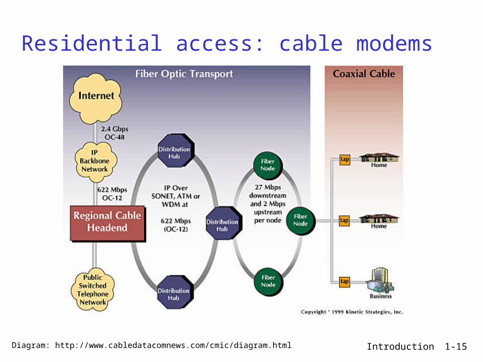
Residential access: cable modems
HFC: hybrid fiber coax asymmetric: up to 30Mbps downstream,
2 Mbps upstream network of cable and fiber attaches homes
to ISP router homes share access to router
deployment: available via cable TV companies
Introduction 1-15
Residential access: cable modems
Diagram: http://www.cabledatacomnews.com/cmic/diagram.html

Introduction 1-16
Cable Network Architecture: Overview
home
cable headend
cable distributionnetwork (simplified)
Typically 500 to 5,000 homes

Introduction 1-17
Cable Network Architecture: Overview
home
cable headend
cable distributionnetwork
server(s)

Introduction 1-18
Cable Network Architecture: Overview
home
cable headend
cable distributionnetwork (simplified)

Introduction 1-19
Cable Network Architecture: Overview
home
cable headend
cable distributionnetwork
Channels
VIDEO
VIDEO
VIDEO
VIDEO
VIDEO
VIDEO
DATA
DATA
CONTROL
1 2 3 4 5 6 7 8 9
FDM (more shortly):

Introduction 1-20
Company access: local area networks
company/univ local area network (LAN) connects end system to edge router
Ethernet: 100Mbps, 1Gbps,
10Gbps Ethernet modern configuration:
end systems connect into Ethernet switch
LANs: chapter 5

Introduction 1-21
Wireless access networks
shared wireless access network connects end system to router via base station aka “access
point”
wireless LANs: 802.11a/b/g (WiFi): 11 or 54
Mbps
wider-area wireless access provided by telco operator ~1Mbps over cellular system
(EVDO, HSDPA) next up (?): WiMAX (10’s Mbps)
over wide area: 20Mbps in real world now
basestation
mobilehosts
router

Introduction 1-22
Home networks
Typical home network components: DSL or cable modem router/firewall/NAT Ethernet wireless access point
wirelessaccess point
wirelesslaptops
router/firewall
cablemodem
to/fromcable
headend
Ethernet

Introduction 1-23
Physical Media
Bit: propagates betweentransmitter/rcvr pairs
physical link: what lies between transmitter & receiver
guided media: signals propagate in solid
media: copper, fiber, coax
unguided media: signals propagate freely,
e.g., radio
Twisted Pair (TP) two insulated copper
wires Category 3: traditional
phone wires, 10 Mbps Ethernet
Category 5: 100Mbps Ethernet

Introduction 1-24
Physical Media: coax, fiber
Coaxial cable: two concentric copper
conductors bidirectional broadband:
multiple channels on cable
HFC
Fiber optic cable: glass fiber carrying
light pulses, each pulse a bit
high-speed operation: high-speed point-to-point
transmission (e.g., 10’s-100’s Gps)
low error rate: repeaters spaced far apart ; immune to electromagnetic noise

Introduction 1-25
Physical media: radio
signal carried in electromagnetic spectrum
no physical “wire” bidirectional propagation
environment effects: reflection obstruction by objects interference
Radio link types: LAN (e.g., Wifi)
11Mbps, 54 Mbps
wide-area (e.g., cellular) 3G cellular: ~ 1 Mbps WiMAX: 20Mbps
satellite Kbps to 45Mbps channel
(or multiple smaller channels)
270 msec end-end delay

Introduction 1-26
Chapter 1: roadmap
1.1 What is the Internet?1.2 Network edge
end systems, access networks, links
1.3 Network core circuit switching, packet switching, network structure
1.4 Delay, loss and throughput in packet-switched networks
1.5 Protocol layers, service models1.7 History

mesh of interconnected routers
the fundamental question: how is data transferred through net? circuit switching:
dedicated circuit per call:
packet-switching: data sent thru net in discrete “chunks”
Introduction 1-27
The Network Core
telephone net

Introduction 1-28
Network Core: Circuit Switching
End-end resources reserved for “call”
link bandwidth, switch capacity
dedicated resources: no sharing
circuit-like (guaranteed) performance
call setup required

Introduction 1-29
Network Core: Circuit Switching
network resources (e.g., bandwidth) divided into “pieces”
pieces allocated to calls
resource piece idle if not used by owning call (no sharing)
dividing link bandwidth into “pieces” frequency division time division

Introduction 1-30
Circuit Switching: FDM and TDM
FDM
frequency
time
TDM
frequency
time
4 users
Example:

Introduction 1-31
Numerical example
How long does it take to send a file of 640,000 bits from host A to host B over a circuit-switched network? All links are 1.536 Mbps Each link uses TDM with 24 slots/sec 500 msec to establish end-to-end circuit
Let’s work it out! 640K / (1536K/24) + .5 = 10.5 sec

Introduction 1-32
Network Core: Packet Switching
each end-end data stream divided into packets
user A, B packets share network resources
each packet uses full link bandwidth
resources used as needed
resource contention: aggregate resource
demand can exceed amount available
congestion: packets queue, wait for link use
store and forward: packets move one hop at a time Node receives complete
packet before forwarding
Bandwidth division into “pieces”
Dedicated allocationResource reservation

Introduction 1-33
Packet Switching: Statistical Multiplexing
Sequence of A & B packets does not have fixed pattern, bandwidth shared on demand statistical multiplexing.
TDM: each host gets same slot in revolving TDM frame.
A
B
C100 Mb/sEthernet
1.5 Mb/s
D E
statistical multiplexing
queue of packetswaiting for output
link

Introduction 1-34
Packet-switching: store-and-forward
takes L/R seconds to transmit (push out) packet of L bits on to link at R bps
store and forward: entire packet must arrive at router before it can be transmitted on next link
delay = 3L/R (assuming zero propagation delay)
Example: L = 7.5 Mbits R = 1.5 Mbps transmission delay =
15 sec
R R RL
more on delay shortly …

Introduction 1-35
Packet switching versus circuit switching
1 Mb/s link each user:
100 kb/s when “active”
active 10% of time
circuit-switching: 10 users
packet switching: with 35 users,
probability > 10 active at same time is less than .0004
Packet switching allows more users to use network!
N users
1 Mbps link
Q: how did we get value 0.0004?

Introduction 1-36
Packet switching versus circuit switching
great for bursty data resource sharing simpler, no call setup
excessive congestion: packet delay and loss protocols needed for reliable data transfer,
congestion control Q: How to provide circuit-like behavior?
bandwidth guarantees needed for audio/video apps
still an unsolved problem (chapter 7)
Is packet switching a “slam dunk winner?”

Introduction 1-37
Internet structure: network of networks
roughly hierarchical at center: “tier-1” ISPs
E.g., Verizon, Sprint, AT&T, Cable and Wireless, national/international coverage
treat each other as equals
Tier 1 ISP
Tier 1 ISP
Tier 1 ISP
Tier-1 providers interconnect (peer) privately

Introduction 1-38
Tier-1 ISP: e.g., Sprint
…
to/from customers
peering
to/from backbone
….
………
POP: point-of-presence

Introduction 1-39
Internet structure: network of networks
“Tier-2” ISPs: smaller (often regional) ISPs Connect to one or more tier-1 ISPs, possibly other tier-2 ISPs E.g.: UUNet Europe, Singapore telecom
Tier 1 ISP
Tier 1 ISP
Tier 1 ISP
Tier-2 ISPTier-2 ISP
Tier-2 ISP Tier-2 ISP
Tier-2 ISP
Tier-2 ISP pays tier-1 ISP for connectivity to rest of Internet tier-2 ISP is customer oftier-1 provider
Tier-2 ISPs also peer privately with each other.

Introduction 1-40
Internet structure: network of networks
“Tier-3” ISPs and local ISPs last hop (“access”) network (closest to end systems) Tier-3: Turkish Telecom, Minnesota Regional Network
Tier 1 ISP
Tier 1 ISP
Tier 1 ISP
Tier-2 ISPTier-2 ISP
Tier-2 ISP Tier-2 ISP
Tier-2 ISP
localISPlocal
ISPlocalISP
localISP
localISP Tier 3
ISP
localISP
localISP
localISP
Local and tier- 3 ISPs are customers ofhigher tier ISPsconnecting them to rest of Internet

Introduction 1-41
Internet structure: network of networks
a packet passes through many networks!
Tier 1 ISP
Tier 1 ISP
Tier 1 ISP
Tier-2 ISPTier-2 ISP
Tier-2 ISP Tier-2 ISP
Tier-2 ISP
localISPlocal
ISPlocalISP
localISP
localISP Tier 3
ISP
localISP
localISP
localISP

Introduction 1-42
Chapter 1: roadmap
1.1 What is the Internet?1.2 Network edge
end systems, access networks, links
1.3 Network core circuit switching, packet switching, network structure
1.4 Delay, loss and throughput in packet-switched networks
1.5 Protocol layers, service models1.6 Networks under attack: security1.7 History

Introduction 1-43
How do loss and delay occur?packets queue in router buffers packet arrival rate to link exceeds output link
capacity packets queue, wait for turn
A
B
packet being transmitted (delay)
packets queueing (delay)
free (available) buffers: arriving packets dropped (loss) if no free buffers

Introduction 1-44
Four sources of packet delay
1. nodal processing: check bit errors determine output link
A
B
propagation
transmission
nodalprocessing queueing
2. queueing time waiting at output
link for transmission depends on
congestion level of router

Introduction 1-45
Delay in packet-switched networks3. Transmission delay: R=link bandwidth
(bps) L=packet length (bits) time to send bits into
link = L/R
4. Propagation delay: d = length of physical
link s = propagation speed in
medium (~2x10⁸ m/sec) propagation delay = d/s
A
B
propagation
transmission
nodalprocessing queueing
Note: s and R are very different quantities!

Introduction 1-46
Caravan analogy
cars “propagate” at 100 km/hr
toll booth takes 12 sec to service car (transmission time)
car~bit; caravan ~ packet Q: How long until caravan
is lined up before 2nd toll booth?
toll booth
toll booth
ten-car caravan
100 km
100 km
Time to “push” entire caravan through toll booth onto highway = 12*10 = 120 sec
Time for last car to propagate from 1st to 2nd toll both: 100km/(100km/hr)= 1 hr
A: 62 minutes

Introduction 1-47
Caravan analogy (more)
Cars now “propagate” at 1000 km/hr
Toll booth now takes 1 min to service a car
Q: Will cars arrive to 2nd booth before all cars serviced at 1st booth?
Yes! After 7 min, 1st car at 2nd booth and 3 cars still at 1st booth.
1st bit of packet can arrive at 2nd router before packet is fully transmitted at 1st router! See Ethernet applet at AWL
Web site
toll booth
toll booth
ten-car caravan
100 km
100 km

Introduction 1-48
Nodal delay
dproc = processing delay typically a few microsecs or less
dqueue = queuing delay depends on congestion, and usually dominates the nodal
delay
dtrans = transmission delay = L/R, significant for low-speed links
dprop = propagation delay a few microsecs to hundreds of msecs
proptransqueueprocnodal ddddd

Introduction 1-49
Queueing delay (revisited)
R=link bandwidth (bps) L=packet length (bits) a=average packet
arrival rate
traffic intensity = La/R
La/R ~ 0: average queueing delay small La/R -> 1: delays become large La/R > 1: more “work” arriving than can
be serviced, average delay infinite!

“Real” Internet delays and routes
What do “real” Internet delay & loss look like? Traceroute program: provides delay
measurement from source to router along end-end Internet path towards destination. For all i: sends three packets that will reach router i on path
towards destination router i will return packets to sender sender times interval between transmission and
reply.
Introduction 1-50
3 probes
3 probes
3 probes

“Real” Internet delays and routes
1 1890mpl-idf-vln-122.northwestern.edu (129.105.100.1) 0.287 ms 0.211 ms 0.193 ms 2 lev-mdf-6-vln-54.northwestern.edu (129.105.253.53) 0.431 ms 0.315 ms 0.321 ms 3 abbt-mdf-1-vln-902.northwestern.edu (129.105.253.222) 0.991 ms 0.950 ms 1.151 ms 4 abbt-mdf-4-ge-0-1-0.northwestern.edu (129.105.253.22) 1.659 ms 1.255 ms 1.520 ms 5 starlight-lsd6509.northwestern.edu (199.249.169.6) 1.713 ms 1.368 ms 1.278 ms 6 206.220.240.154 (206.220.240.154) 1.284 ms 1.204 ms 1.279 ms 7 206.220.240.105 (206.220.240.105) 2.892 ms 2.003 ms 2.808 ms 8 202.112.61.5 (202.112.61.5) 116.475 ms 196.663 ms 241.792 ms 9 sl-gw25-stk-1-2.sprintlink.net (144.223.71.221) 145.502 ms 150.033 ms 151.715 ms10 sl-bb21-stk-8-1.sprintlink.net (144.232.4.225) 166.762 ms 177.180 ms 166.235 ms11 sl-bb21-hk-2-0.sprintlink.net (144.232.20.28) 331.858 ms 340.613 ms 346.332 ms12 sl-gw10-hk-14-0.sprintlink.net (203.222.38.38) 346.842 ms 356.915 ms 366.916 ms13 sla-cent-3-0.sprintlink.net (203.222.39.158) 482.426 ms 495.908 ms 509.712 ms14 202.112.61.193 (202.112.61.193) 515.548 ms 501.186 ms 509.868 ms15 202.112.36.226 (202.112.36.226) 537.994 ms 561.658 ms 541.695 ms16 shnj4.cernet.net (202.112.46.78) 451.750 ms 263.390 ms 342.306 ms17 hzsh3.cernet.net (202.112.46.134) 349.855 ms 366.082 ms 380.849 ms18 zjufw.zju.edu.cn (210.32.156.130) 350.693 ms 394.553 ms 366.636 ms19 * * *20 * * *21 www.zju.edu.cn (210.32.0.9) 353.623 ms 397.532 ms 396.326 ms
traceroute: zappa.cs.nwu.edu to www.zju.edu.cnThree delay measurements from Zappa.cs.cs.nwu.edu to 1890mpl-idf-vln-
122.northwestern.edu
* means no reponse (probe lost, router not replying)
trans-oceaniclink

Introduction 1-52
Packet loss
queue (aka buffer) preceding link in buffer has finite capacity
packet arriving to full queue dropped (aka lost)
lost packet may be retransmitted by previous node, by source end system, or not at allA
B
packet being transmitted
packet arriving tofull buffer is lost
buffer (waiting area)

Introduction 1-53
Throughput
throughput: rate (bits/time unit) at which bits transferred between sender/receiver instantaneous: rate at given point in time average: rate over longer period of time
server, withfile of F bits
to send to client
link capacity
Rs bits/sec
link capacity
Rc bits/sec pipe that can carry
fluid at rate
Rs bits/sec)
pipe that can carryfluid at rate
Rc bits/sec)
server sends bits
(fluid) into pipe

Introduction 1-54
Throughput (more)
Rs < Rc What is average end-end throughput?
Rs bits/sec Rc bits/sec
Rs > Rc What is average end-end throughput?
Rs bits/sec Rc bits/sec
link on end-end path that constrains end-end throughput
bottleneck link

Introduction 1-55
Throughput: Internet scenario
10 connections (fairly) share backbone bottleneck link R
bits/sec
Rs
Rs
Rs
Rc
Rc
Rc
R
per-connection end-end throughput: min(Rc,Rs,R/10)
in practice: Rc or Rs is often bottleneck
Introduction 1-56
Chapter 1: roadmap
1.1 What is the Internet?1.2 Network edge
end systems, access networks, links
1.3 Network core circuit switching, packet switching, network structure
1.4 Delay, loss and throughput in packet-switched networks
1.5 Protocol layers, service models1.7 History

Introduction 1-57
Protocol “Layers”Networks are
complex! many “pieces”:
hosts routers links of various
media applications protocols hardware,
software
Question: Is there any hope of organizing structure of
network?
Or at least our discussion of networks?

Introduction 1-58
Organization of air travel
a series of steps
ticket (purchase)
baggage (check)
gates (load)
runway takeoff
airplane routing
ticket (complain)
baggage (claim)
gates (unload)
runway landing
airplane routing
airplane routing

Introduction 1-59
ticket (purchase)
baggage (check)
gates (load)
runway (takeoff)
airplane routing
departureairport
arrivalairport
intermediate air-trafficcontrol centers
airplane routing airplane routing
ticket (complain)
baggage (claim
gates (unload)
runway (land)
airplane routing
ticket
baggage
gate
takeoff/landing
airplane routing
Layering of airline functionality
Layers: each layer implements a service via its own internal-layer actions relying on services provided by layer below

Why layering?
Dealing with complex systems: Explicit structure allows identification,
relationship of complex system’s pieces layered reference model for discussion
Modularization eases maintenance, updating of system change of implementation of layer’s service
transparent to rest of system e.g., change in gate procedure doesn’t affect
rest of system Layering considered harmful?

Introduction 1-61
Internet protocol stack application: supporting network
applications FTP, SMTP, HTTP
transport: process-process data transfer TCP, UDP
network: routing of datagrams from source to destination IP, routing protocols
link: data transfer between neighboring network elements PPP, Ethernet
physical: bits “on the wire”
application
transport
network
link
physical

Introduction 1-62
ISO/OSI reference model presentation: allow applications
to interpret meaning of data, e.g., encryption, compression, machine-specific conventions
session: synchronization, checkpointing, recovery of data exchange
Internet stack “missing” these layers! these services, if needed, must
be implemented in application needed?
application
presentation
session
transport
network
link
physical

Introduction 1-63
sourceapplicatio
ntransportnetwork
linkphysical
HtHn M
segment Ht
datagram
destination
application
transportnetwork
linkphysical
HtHnHl M
HtHn M
Ht M
M
networklink
physical
linkphysical
HtHnHl M
HtHn M
HtHn M
HtHnHl M
router
switch
Encapsulationmessage M
Ht M
Hn
frame

Introduction 1-64
Chapter 1: roadmap
1.1 What is the Internet?1.2 Network edge
end systems, access networks, links
1.3 Network core circuit switching, packet switching, network structure
1.4 Delay, loss and throughput in packet-switched networks
1.5 Protocol layers, service models1.6 Networks under attack: security1.7 History

Introduction 1-65
Internet History
1961: Kleinrock - queueing theory shows effectiveness of packet-switching
1964: Baran - packet-switching in military nets
1967: ARPAnet conceived by Advanced Research Projects Agency
1969: first ARPAnet node operational
1972: ARPAnet public
demonstration NCP (Network Control
Protocol) first host-host protocol
first e-mail program ARPAnet has 15 nodes
1961-1972: Early packet-switching principles

Introduction 1-66
Internet History
1970: ALOHAnet satellite network in Hawaii
1974: Cerf and Kahn - architecture for interconnecting networks
1976: Ethernet at Xerox PARC
late70’s: proprietary architectures: DECnet, SNA, XNA
late 70’s: switching fixed length packets (ATM precursor)
1979: ARPAnet has 200 nodes
Cerf and Kahn’s internetworking principles: minimalism, autonomy -
no internal changes required to interconnect networks
best effort service model stateless routers decentralized control
define today’s Internet architecture
1972-1980: Internetworking, new and proprietary nets

Introduction 1-67
Internet History
1983: deployment of TCP/IP
1982: smtp e-mail protocol defined
1983: DNS defined for name-to-IP-address translation
1985: ftp protocol defined
1988: TCP congestion control
new national networks: Csnet, BITnet, NSFnet, Minitel
100,000 hosts connected to confederation of networks
1980-1990: new protocols, a proliferation of networks

Introduction 1-68
Internet History
Early 1990’s: ARPAnet decommissioned
1991: NSF lifts restrictions on commercial use of NSFnet (decommissioned, 1995)
early 1990s: Web hypertext [Bush 1945,
Nelson 1960’s] HTML, HTTP: Berners-Lee 1994: Mosaic, later
Netscape late 1990’s:
commercialization of the Web
Late 1990’s – 2000’s: more killer apps: instant
messaging, P2P file sharing
network security to forefront
est. 50 million host, 100 million+ users
backbone links running at Gbps
1990, 2000’s: commercialization, the Web, new apps

Introduction 1-69
Internet History
2007: ~500 million hosts Voice, Video over IP P2P applications: BitTorrent
(file sharing) Skype (VoIP), PPLive (video)
more applications: YouTube, gaming
wireless, mobility

Introduction 1-70
Introduction: SummaryCovered a “ton” of
material! Internet overview what’s a protocol? network edge, core,
access network packet-switching
versus circuit-switching
Internet structure performance: loss,
delay, throughput layering, service models history
You now have: context, overview,
“feel” of networking more depth, detail
to follow!