introduction to combined heat and power - cummins inc. chp... · introduction to combined heat and...
TRANSCRIPT

PowerHour webinar series for consulting engineersExperts you trust. Excellence you count on.
Introduction to Combined Heat and Power
November 8, 2016 11:00 PST / 2:00 EST
(1PDH issued by Cummins)

Welcome!
PowerHour is designed to help our engineer partners to…
Keep up to date on products, technology, and codes and standards development
Interact with Cummins experts and gain access to ongoing technical support
Participate at your convenience, live or on-demand
Earn PDH
Technical tips:
Audio is available through teleconference, or your computer (don’t forget to unmute)
You are in “listen only” mode throughout the event
Use the WebEx Q&A Panel to submit questions, comments, and feedback
throughout the event. We will provide sufficient Q&A time after presentation
If you lose audio, get disconnected, or experience a poor connection, please
disconnect and reconnect
Report technical issues using the WebEx Q&A Panel, or email
PowerHour Experts you trust. Excellence you count on.
Meet your panelists
3PowerHour Experts you trust. Excellence you count on.
Emiliano Pantner,
Senior Application Engineer, EIT
Cummins presenter: Cummins facilitator:Tom Bakritzes,
Global Sales Training Manager
Your local Cummins contacts:
AZ, ID, NM, NV: Carl Knapp ([email protected]), Rocky Mountain Region
CO, MT, ND, UT, WY: Joe Pekarek ([email protected]), Rocky Mountain Region
IL, IA, NE, SD: John Kilinskis ([email protected]), Central Region
WI, MN, ND: Michael Munson ([email protected]), Central Region
MO, KS: Earnest Glaser ([email protected]), Central Region
TX: Scott Thomas ([email protected]), Gulf Region
FL, GA, NC: Robert Kelly ([email protected]), South Region
IN, KY, OH, TN, WV: Thomas Stadulis ([email protected]), East Region
West Canada: Rick Smith ([email protected])
For other states and territories, email [email protected] or visit http://power.cummins.com/sales-service-locator
Course Objectives
Participants will be able to:
Define CHP project concepts and terminology to discuss
customer CHP opportunities
Identify economic, design, and operational criteria to
propose different CHP configurations and equipment
Identify the key tools and data required to create
informed CHP feasibility studies

CHP Overview
CHP, Combined Heat and Power
– The utilization of both heat and electric energy from a Genset
– Also known as Co-generation or Co-Gen
• US EPA uses the term Co-generation
CHP is not a new technology
– Used in Thomas Edison’s first electric generating plant in 1891
– Used in industrial, institution, and municipal applications today
Cogeneration systems can provide hot water, steam, chilled water,
or all 3 simultaneously

CHP Benefits
Energy efficiency
– Could reach 90% global efficiency
Financial savings
– Energy cost savings
– Attractive return on investment (ROI)
– Potential incentives for fuel efficiency and emissions reduction benefits of CHP
Environmental
– Reduced environmental footprint
• Reduction in CO2, NOx, and particulates compared to central power plant
– Higher efficiency means better conservation of natural resources
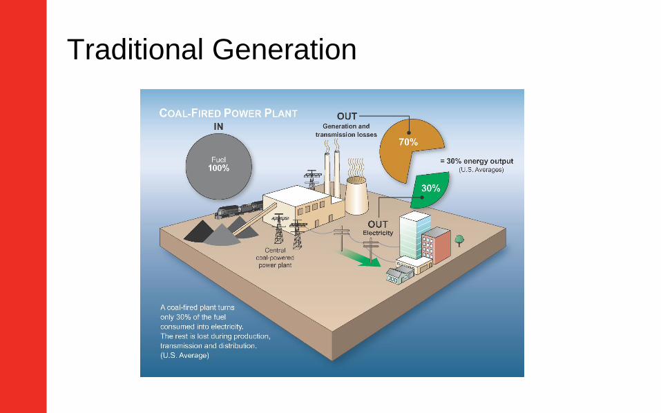
Traditional Generation
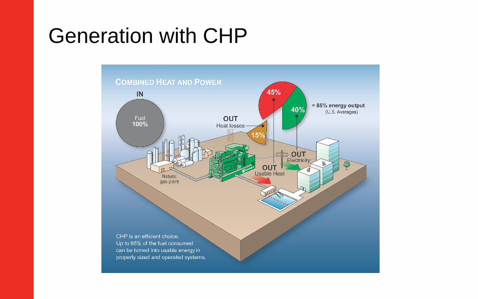
Generation with CHP
Application Considerations
Electrical loads
– Sufficient base electrical load or export capability
Thermal loads
– Sufficient equipment or process that can use the heat energy
Balance between electrical and thermal loads is critical for optimum
CHP performance
– Available heat energy is dependent on the electrical output
– If not balanced, either the excess heat must be dumped or the excess
electrical power exported.
Heat Energy Sources
When to use each heat source?
Heat source temperatures
– Low temperature (LT), or after cooler circuit (~ 40-60 °C, 104-140 °F)
– High temperature (HT), or jacket water circuit (~90-110 °C, 194-230 °F)
– Exhaust (~450-550 °C, 842-1022 °F)
Typical heat uses and components
– Steam production Boiler (exhaust)
– Hot water EGHE, Engine Cooling HX (exhaust and/or HT, LT)
• LT circuit sometimes used as pre-heat to prevent thermal shock
– Cold water Chiller (exhaust and/or HT)

Simplified CHP Schematic
Required Information
Customer
Electrical load profile
Thermal load profile
– Heat transfer media
• Steam, water, oil, etc.
– Process temperatures
• Input and output
– Process flowrates
Cummins (Datasheet)
Genset kW rating
Thermal energy from each
heat source
Heat source flowrates
temperatures

Sample Data Sheet
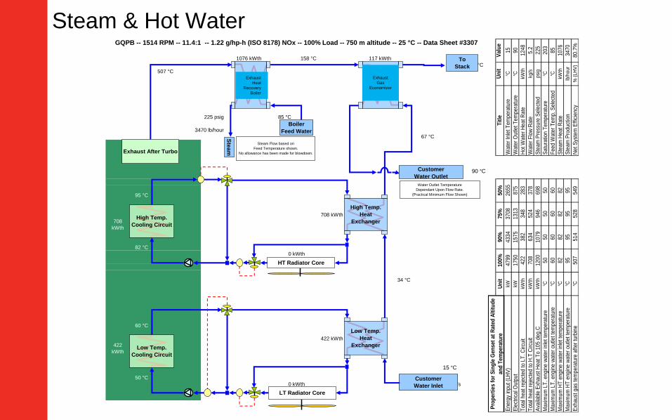
158 °C 117 kWth
120 °C
507 °C
85 °C
67 °C
73 °C
5.2 kg/s
95 °C
708 kWth
708
kWth
82 °C
34 °C
60 °C
422 kWth
422
kWth
50 °C 15 °C
5.2 kg/s
3470 lb/hour
0 kWth
0 kWth
GQPB -- 1514 RPM -- 11.4:1 -- 1.22 g/hp-h (ISO 8178) NOx -- 100% Load -- 750 m altitude -- 25 °C -- Data Sheet #3307
1076 kWth
225 psig
203 °C
Exhaust After Turbo
Low Temp.
Cooling Circuit
Low Temp.
Heat
Exchanger
LT Radiator Core
High Temp.
Cooling Circuit
High Temp.
Heat
Exchanger
HT Radiator Core
Exhaust Gas
Boiler &
Economizer
Exhaust
Gas Heat
Exchanger
To
Stack
Boiler
Feed Water
Ste
am
Customer
Water Inlet
Customer
Water Outlet
Water Outlet Temperature
Dependant Upon Flow Rate.
(Practical Minimum Flow Shown)
Steam Flow based on
Feed Temperature shown.
No allowance has been made for blowdown.
Un
it100%
90%
75%
50%
Un
itV
alu
e
kW4799
4334
3708
2655
°C15
kW1750
1575
1313
875
°C90
kWth
422
382
348
283
kWth
1248
kWth
708
634
524
378
kg/s
5.2
kWth
1200
1079
946
698
psi
g225
°C50
50
50
50
°C203
°C60
60
60
60
°C85
°C82
82
82
82
kWth
1076
°C95
95
95
95
lb/h
our
3470
°C507
514
528
549
% (
LH
V)
80.7
%
Maxi
mum
HT
eng
ine w
ate
r outle
t te
mpera
ture
Ste
am
Pro
du
ctio
n
Exh
aust
gas
tem
pera
ture
aft
er
turb
ine
Net
Sys
tem
Eff
icie
ncy
Maxi
mum
LT
. eng
ine w
ate
r outle
t te
mpera
ture
Fee
d W
ate
r T
em
p.
Sele
cted
Maxi
mum
HT
eng
ine w
ate
r in
let
tem
pera
ture
Ste
am
Heat
Ra
te
Ava
ilable
Exh
aust
Heat
To 1
05 d
eg
.CS
team
Pre
ssure
Sele
cted
Maxi
mum
LT
. eng
ine w
ate
r in
let
tem
pera
ture
Sa
tura
tion T
em
pe
ratu
re
Tota
l heat
reje
cted t
o L
T.
Circu
itH
ot
Wate
r H
eat
Rate
Tota
l heat
reje
cted t
o H
.T C
ircu
itW
ate
r F
low
Rate
Energ
y in
put
(LH
V)
Wa
ter
Inle
t T
em
pe
ratu
re
Ele
ctrica
l Outp
ut
Wa
ter
Ou
tlet
Tem
pera
ture
Pro
pert
ies f
or
Sin
gle
Gen
set
at
Rate
d A
ltit
ud
e
an
d T
em
pera
ture
Tit
le
Exhaust
Gas
Economizer
Exhaust
Heat
Recovery
Boiler
15 °C
90 °C
Steam & Hot Water
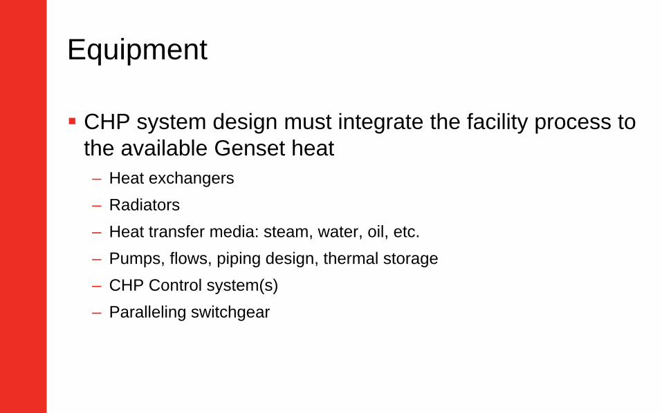
Equipment
CHP system design must integrate the facility process to
the available Genset heat
– Heat exchangers
– Radiators
– Heat transfer media: steam, water, oil, etc.
– Pumps, flows, piping design, thermal storage
– CHP Control system(s)
– Paralleling switchgear
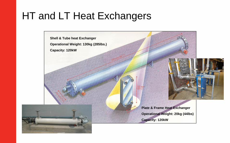
HT and LT Heat Exchangers
Shell & Tube heat Exchanger
Operational Weight: 130kg (285lbs.)
Capacity: 120kW
Plate & Frame Heat Exchanger
Operational Weight: 20kg (44lbs)
Capacity: 120kW
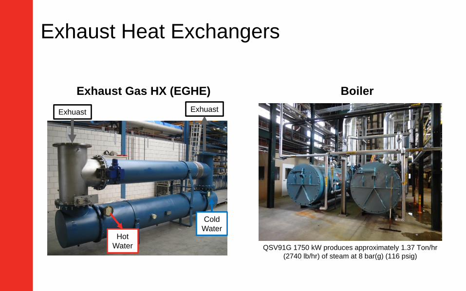
Exhaust Heat Exchangers
Exhaust Gas HX (EGHE) Boiler
Exhuast Exhuast
Cold
WaterHot
Water QSV91G 1750 kW produces approximately 1.37 Ton/hr
(2740 lb/hr) of steam at 8 bar(g) (116 psig)
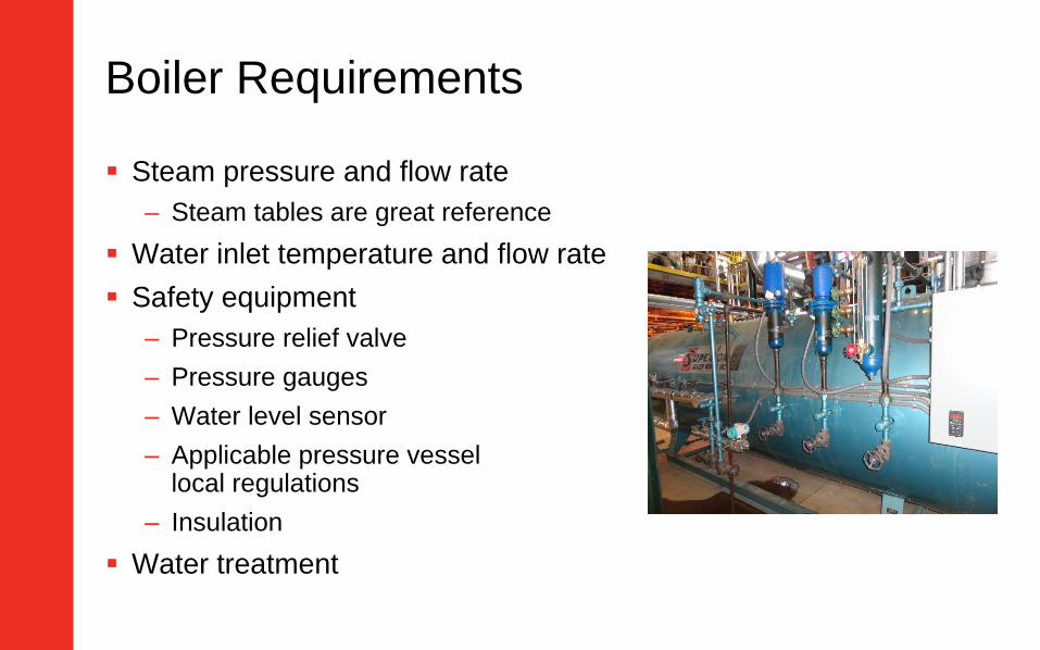
Boiler Requirements
Steam pressure and flow rate
– Steam tables are great reference
Water inlet temperature and flow rate
Safety equipment
– Pressure relief valve
– Pressure gauges
– Water level sensor
– Applicable pressure vessellocal regulations
– Insulation
Water treatment

Utilizing the Exhaust
Equipment using exhaust as heat source must be bypassed during
engine start-up
Water, or heat transfer media, must be running through heat
exchanging equipment before start-up
Having a common exhaust pipe will affect heat output when not all
engines are running
– Affects heat exchanging equipment size
Valve, bypass pipe, non-common exhaust, control, purging
After-treatment equipment must be installed upstream heat
exchangers/boilers
– After-treatment has a specific temperature operating range
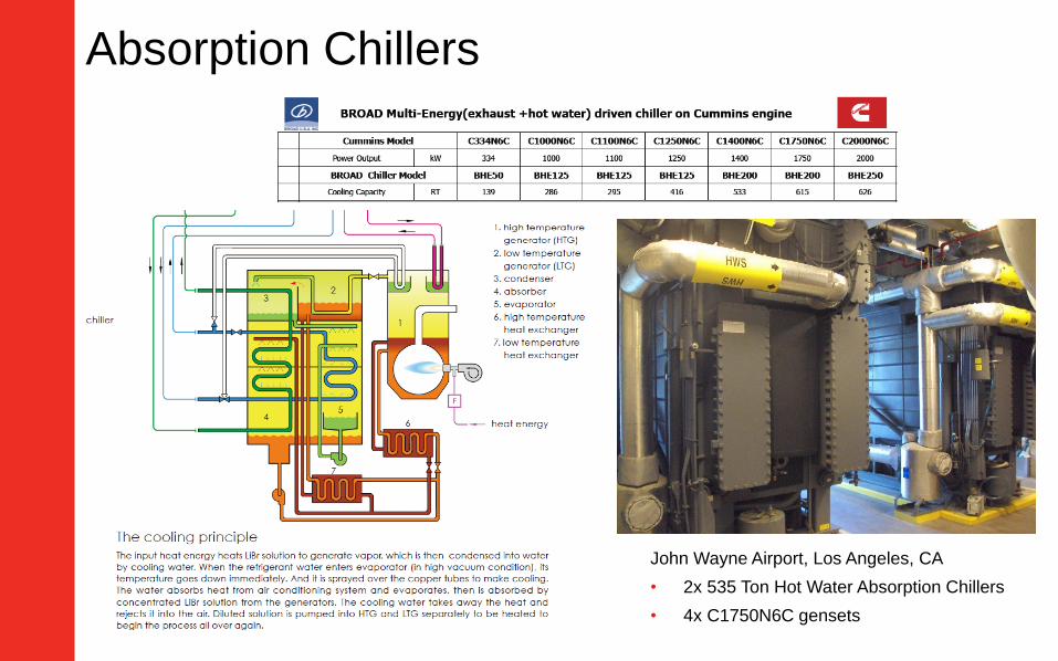
Absorption Chillers
John Wayne Airport, Los Angeles, CA
• 2x 535 Ton Hot Water Absorption Chillers
• 4x C1750N6C gensets
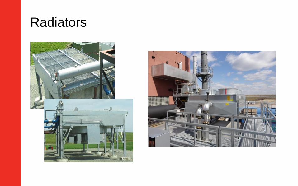
Radiators

General Installation Considerations
Pressure & temperature indicators
Thermostatic valves
– Better temperature control
– Higher efficiency
– Lower temperature to the cooling circuit affects heat energy output, temp, flow rate
Pipe insulation
Pumps need to be installed before heat exchanging equipment
– Pressure relief valve needs to be installed right after pump outlet to protect downstream equipment
Isolation valves are recommended for each equipment for better serviceability
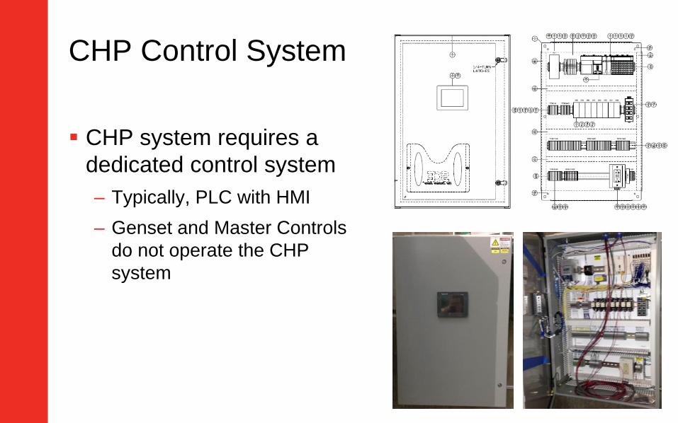
CHP Control System
CHP system requires a
dedicated control system
– Typically, PLC with HMI
– Genset and Master Controls
do not operate the CHP
system
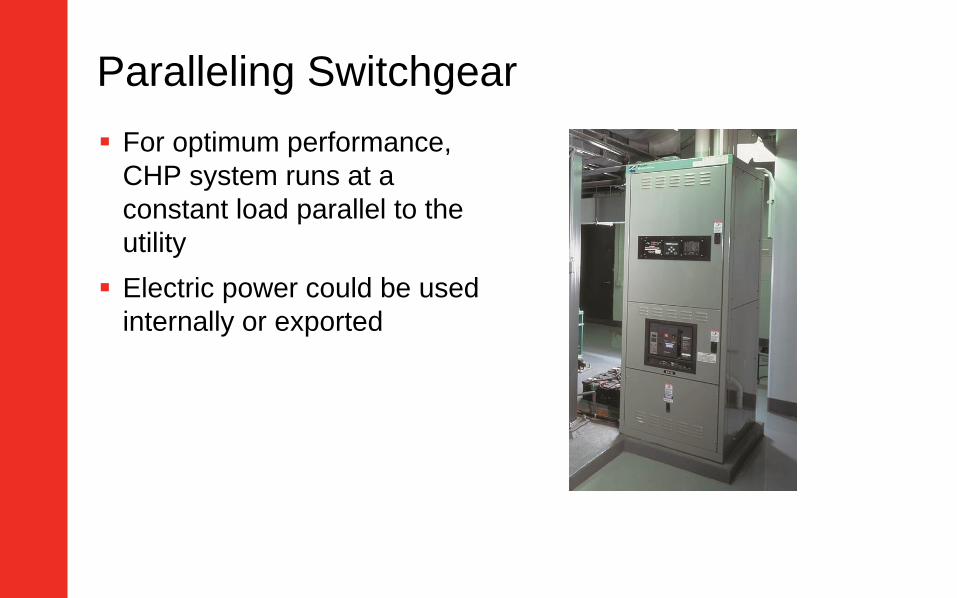
Paralleling Switchgear
For optimum performance,
CHP system runs at a
constant load parallel to the
utility
Electric power could be used
internally or exported
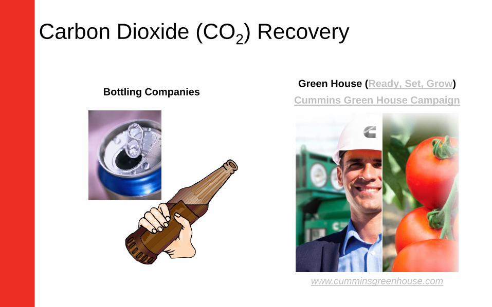
Carbon Dioxide (CO2) Recovery
Bottling CompaniesGreen House (Ready, Set, Grow)
Cummins Green House Campaign
www.cumminsgreenhouse.com

Boiler
CO2
Recovery
Plant
HT
Radiator
Bottling
Plant
Chiller
92 C70 m3/h
75 C
458 C4x 11,772
kg/h(47,088 kg/h)
30 C122 m3/h (total)
16 C or lower
4x 3,475 kg/h(13,900 kg/h)
458 C4x 8,297 kg/h(33,188 kg/h)
Exhaust
Exhaust
HEX
65 C4x 78.3 L/min(313.2 L/min)
18-20 bar to be stored in liquid tanks
Reduced to 12 bar max for line process
4x 807.5 kg/h(3230 kg/h) @ 7bar
?? C
1096 kW
Dry
Cooling
1750 kWe
Exhaust
Steam
Chilled
Water
CO2
Silencer
92 C70 m3/h
80 C
29 C117 m3/h
36 C
Bottling Company Example
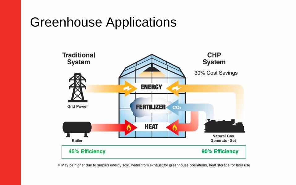
Greenhouse Applications
May be higher due to surplus energy sold, water from exhaust for greenhouse operations, heat storage for later use
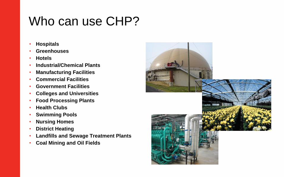
Who can use CHP?
• Hospitals
• Greenhouses
• Hotels
• Industrial/Chemical Plants
• Manufacturing Facilities
• Commercial Facilities
• Government Facilities
• Colleges and Universities
• Food Processing Plants
• Health Clubs
• Swimming Pools
• Nursing Homes
• District Heating
• Landfills and Sewage Treatment Plants
• Coal Mining and Oil Fields
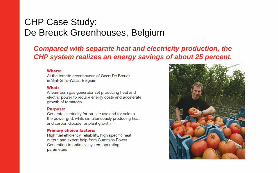
CHP Case Study: De Breuck Greenhouses, Belgium
Compared with separate heat and electricity production, the
CHP system realizes an energy savings of about 25 percent.
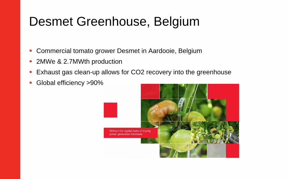
Desmet Greenhouse, Belgium
Commercial tomato grower Desmet in Aardooie, Belgium
2MWe & 2.7MWth production
Exhaust gas clean-up allows for CO2 recovery into the greenhouse
Global efficiency >90%
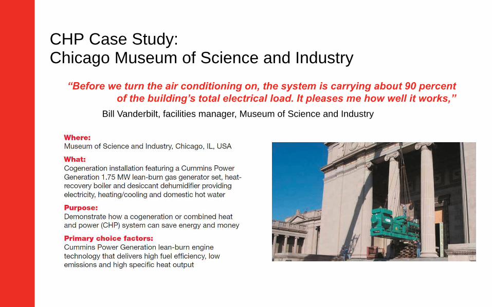
CHP Case Study: Chicago Museum of Science and Industry
“Before we turn the air conditioning on, the system is carrying about 90 percent
of the building’s total electrical load. It pleases me how well it works,”
Bill Vanderbilt, facilities manager, Museum of Science and Industry
Facility evaluation for CHP
1. Have all reasonable steps been taken to reduce both electric and heat energy
consumption?
2. Is the base electrical load of the facility greater than an available Genset
continuous rating?
3. Is the thermal load of the facility greater than the available thermal energy from
the Genset?
4. Is the duration of simultaneous need for heating/cooling and electric power greater
than 6000 hours/year?
5. Are electric rates high in relation to NG rates?
6. Is the site suitable for installation of a co-gen system?
7. Is reliability of electric service a major economic concern?
8. Has an economic analysis been done?
Summary
CHP can provide several advantages including energy
efficiency, reduced environmental footprint, and financial
savings
Start by understanding site energy use – both heat and
electricity
CHP system design depends on energy utilization, customer
processes, site considerations, and Genset characteristics
Contact Cummins Power Generation for assistance in
performing facility evaluation and ROI analysis
Q&A
Type your questions, comments, feedback in the WebEx
Q&A box. We will get to as many questions as we can
We will publish consolidated FAQ along with
presentation and webinar recording on
powersuite.cummins.comYour local Cummins contacts:
AZ, ID, NM, NV: Carl Knapp ([email protected]), Rocky Mountain Region
CO, MT, ND, UT, WY: Joe Pekarek ([email protected]), Rocky Mountain Region
Northern IL, IA: John Kilinskis ([email protected]), Central Region
UP of MI, MN, East ND, WI: Michael Munson ([email protected]), Central Region
NB, SD, West MO, KS: Earnest Glaser ([email protected]), Central Region
South IL, East MO: Jeff Yates ([email protected]), Central Region
TX: Scott Thomas ([email protected]), Gulf Region
FL, GA, SC, NC and Eastern TN: Robert Kelly ([email protected]), South Region
NY, NJ, CT, PA, MD: Charles Attisani ([email protected] ): East Region
CA, HI: Brian E Pumphrey ([email protected])
WA, OR, AK: Tom Tomlinson ([email protected])
For other states and territories, email [email protected] or visit http://power.cummins.com/sales-service-locator

Closing
Watch out for a follow-up email including– A Link to webinar recording and presentation
– A PDH Certificate
Visit powersuite.cummins.com for – PowerHour webinar recording, presentation and FAQ archive
– Other Cummins Continuing Education programs
– Sizing and spec development tool
Please contact Mohammed Gulam if you have any questions related
to the PowerHour webinar ([email protected])