introduction to distributed generation
TRANSCRIPT

7/27/2019 Introduction to Distributed Generation
http://slidepdf.com/reader/full/introduction-to-distributed-generation 1/21
An Introduction toDistributed GenerationInterconnection
107061 03/04

7/27/2019 Introduction to Distributed Generation
http://slidepdf.com/reader/full/introduction-to-distributed-generation 2/21
An Introduction to Distributed Generation Interconnection
— Table of Contents —
An Introduction to Distributed Generation Interconnection
How to use this manual . . . . . . . . . . . . . . . . . . . . . . . . . . . . . . . . . . . . . . . . . . . 4
Introduction to Distributed Generation . . . . . . . . . . . . . . . . . . . . . . . . . . . . . . . . 4
Forms of Distributed Generation . . . . . . . . . . . . . . . . . . . . . . . . . . . . . . . . . . . 5-7
Distributed Generation technologies that require a Supplied Fuel
1. Microturbines
2. Fuel Cells
3. Stirling Engines4. Internal Combustion Reciprocating Engines
Distributed Generation technologies that do not require a Supplied Fuel . . . . . . . 8
1. Solar or Photovoltaic2. Wind
Inverter vs. Non-Inverter Technologies . . . . . . . . . . . . . . . . . . . . . . . . . . . . . . . . 9
Air Permitting a Distributed Resource . . . . . . . . . . . . . . . . . . . . . . . . . . . . . . . . 10
Electrical Interconnection of Distributed Generation . . . . . . . . . . . . . . . . . . . 10-14General Design RequirementsDistributed Generation Equipment Protection
Commissioning and Utility Acceptance Testing of Distributed Generation . . . . . . 15
Distributed Generation using Bio-fuels and the impact of Siloxanes . . . . . . . . . . 16
Distributed Resources operating as CHP or Trigeneration . . . . . . . . . . . . . . . . . . 17
Glossary of Distributed Resource Terms . . . . . . . . . . . . . . . . . . . . . . . . . . . . 19-21

7/27/2019 Introduction to Distributed Generation
http://slidepdf.com/reader/full/introduction-to-distributed-generation 3/21
An Introduction to Distributed Generation Interconnection
— Appendices —
An Introduction to Distributed Generation Interconnection
Appendix 1: Wisconsin Distributed Generation Interconnection Guidelines
Appendix 2: PSCW Standard Distributed Generation Application Form (Generation 20kW or less)
Appendix 3: PSCW Distributed Generation Application Form (Generation of Greater than 20kW to 15MW)
Appendix 4: PSCW D. G. Interconnection Agreement (20kW or less)
Appendix 5: PSCW D. G. Interconnection Agreement (20kW to 15MW)
Appendix 6: Alliant Energy-WPL Tariff, PARALLEL GENERATION - (in Excess of 20kW) ELECTRIC
Appendix 7: Alliant Energy-WPL Tariff, PARALLEL GENERATION - (20kW OR LESS) ELECTRIC
Appendix 8: Alliant Energy Technical Guidelines for Interconnection of Parallel-OperaGeneration Connected to the Distribution System
Appendix 9: Alliant Energy Distributed Generation Interconnection Request Form
Appendix 10: Alliant Energy Master Interconnection Agreement

7/27/2019 Introduction to Distributed Generation
http://slidepdf.com/reader/full/introduction-to-distributed-generation 4/21
How to use this manual
In conjunction with the accompanying video presentation, the purpose of this manual is to provide anoverview of the technologies and issues involved in the design, utilization and interconnection ofDistributed Generation (DG) to the utility grid.
The U.S. Department of Energy (DOE) commissioned the development of this manual and the accompanying video due to the growing market for DG, the relative newness of some of the generation tech
nology, and the importance of correct interconnection with the electric grid. Its purpose is to provide aoverview to those who are considering using the technology, or to those who may be in a position toinspect or to approve the installation of such technology.
The manual and video are results of a collaborative effort from the U.S. DOE, the State of WisconsinDivision of Energy, Alliant Energy, and Unison Solutions. Neither this manual nor the video are meant be a comprehensive study of Distributed Generation, but rather an overview with which to create famiiarity with the subject matter and the relevant issues.
As always, consult local authorities to receive the information appropriate to each project. Ordinancespermitting policies and regulations may vary by installation, technology, locality, utility and state. (See
References section for sources of information.) Actual project requirements may differ from what isoffered in this manual.
Introduction
In general terms, Distributed Generation (DG) is any type of electrical generator or static inverterproducing alternating current that (a) has the capability of parallel operation with the utility distributionsystem, or (b) is designed to operate separately from the utility system and can feed a load that can a
be fed by the utility electrical system. A distributed generator is sometimes referred to simply as “genetor”.
Distributed generators include induction and synchronous electrical generators as well as any typeof electrical inverter capable of producing A/C power. An Emergency or Standby Generation System idesigned so as to never electrically interconnect or operate in parallel with the utility system. AnInterconnected Generation System is any generator or generation system that can parallel (or has thepotential to be paralleled via design or normal operator control), either momentarily or on acontinuous basis, with the utility system.
The term Distributed Generation is sometimes used interchangeably with the term Distributed
Resources (DR). But DR is intended to encompass non generating technologies such as power storadevices like batteries and flywheels in addition to generators, while DG is limited to small scale (lessthan 20 MW) electrical generation located close to point of use. Unlike central power plant generationDG often utilizes the waste heat from the generation process as an additional form of energy for spacor process heating, dehumidification, or for cooling through absorption refrigeration.

7/27/2019 Introduction to Distributed Generation
http://slidepdf.com/reader/full/introduction-to-distributed-generation 5/21
Forms of Distributed Generation
Distributed Generation technologies that require a Supplied Fuel
1. Microturbines:Microturbines are scaled down turbine engines with integrated generators and power electronics.They are generally characterized by having only one rapidly moving part (moving at 100,000rpm) supported either by air- or liquid-lubricated bearings. The microturbine generates high-fre-
quency AC power that is rectified by a power electronics package into utility grid-quality, three-phase 400-480v AC power. Microturbines can operate on a wide variety of gaseous and liquidfuels, and have extremely low emissions of nitrogen oxides. Electrical efficiency of microturbinesis in the 25-30 percent range. Although the latest combined cycle gas turbines can achievemaximum output efficiencies nearing 60 percent, the US Environmental Protection Agency andthe Department of Energy notes that average power plant efficiency in the country is 34 percent.Since 5-10 percent of that is lost in transmission and distribution, the national average mayactually be about the same as that of on-site microturbines without heat recovery.
Ancillary heat from microturbines can be used on-site for water and space heating, processdrying, food processing and absorption chilling. Doing so delivers a total system efficiency of at
least 70 percent, and use of the exhaust stream for process drying, greenhouse heating/CO2supplementation and similar tasks yields efficiencies exceeding 90 percent.
Capstone MicroTurbine, 60kW
Capstone MicroTurbine, 30kW

7/27/2019 Introduction to Distributed Generation
http://slidepdf.com/reader/full/introduction-to-distributed-generation 6/21
2. Fuel Cells:A fuel cell is an electromechanical engine. It harnesses the energy released when hydrogen andoxygen combine. This reaction produces electricity, heat and water. Fuel cells produce almost nopollutants and have no moving parts.
In principle, a fuel cell operates like a battery. However,a fuel cell does not run down or require recharging.It will produce energy in the form of electricity and heat
as long as fuel is supplied.
The hydrogen needed for reaction in a fuel cell istypically produced from hydrogen rich fuels suchas natural gas, propane, or methane from biogasrecovery. These hydrogen rich fuels are run througha fuel "reformer" that converts the fuel from its originalcomposition to hydrogen and to carbon dioxide.
3. Stirling Engines:Robert Stirling originally patented “A New Type of Air Engine with Economizer” in 1816.TheStirling engine is also known as an "external combustion engine.” Combustion in the form of asteady flame takes place outside of the sealed chamber or cylinder.The Stirling engine runscleaner and more efficiently than an internal combustion engine.
The Stirling engine derives its power from heating and cooling a gas inside a sealed chamberwith a piston. When the gas is heated, it will expand and build pressure within the sealed cham-ber; thus pushing a piston out. When the gas cools, it will contract and pull the piston in. Theeconomizer, now known as a regenerator, stores heat between the hot and cold cycles.
Proton Exchange Membrane (PEM) Fuel Cell

7/27/2019 Introduction to Distributed Generation
http://slidepdf.com/reader/full/introduction-to-distributed-generation 7/21
4. Internal Combustion Reciprocating Engines:The most common internal-combustion engine is the piston-type.The confined space in whichcombustion occurs is called a cylinder. In each cylinder a piston slides up and down. Oneend of a connecting rod is attached to the bottom of the piston by a joint; the other end ofthe rod clamps around a bearing onone of the throws of a crankshaft; thereciprocating (up-and-down) motionsof the piston rotate the crankshaft,which is connected by suitablegearing or directly to a generator.
Reciprocating Engine/Generator
STM Stirling Engine/Generator (Beta version), 25 kW External View
STM Stirling Engine/Generator (Beta version), 25 kW
Case Open

7/27/2019 Introduction to Distributed Generation
http://slidepdf.com/reader/full/introduction-to-distributed-generation 8/21
Distributed Generation technologies that do not require a Supplied Fuel
1. Solar or Photovoltaic:A solar or photovoltaic (PV) cell is made of special materials called semiconductors, an exampleof which is silicon crystal. The photovoltaic cell is designed to convert light energy into electriccurrent. It is a specially constructed diode, which is an electronic component with positively andnegatively charged fields that force the movement of electric current in only one direction.Theborder between the negative and positive fields is called the diode junction.
When light strikes the cell's exposed active surface, a portion of the light energy is absorbed bythe semiconductor material. The energy knocks electrons loose from their positive and negativesites in the silicon crystal, allowing them to flow freely. Some of the electrons have sufficient ener-gy to cross the diode junction and cannot return to positions on the other side of the junctionwithout passing through an external circuit. This flow of electrons is called current, and by placingmetal contacts on the top and bottom of the photovoltaic cell, current can be drawn off for exter-nal use. Since the current obtained from these devices is small and the voltage is low, they mustbe connected in large series-parallel arrays (solar panels) if useful amounts of energy are to beconverted. Practical devices of this kind are about 10 percent to 15 percent efficient.
2.Wind:Modern wind energy systems consist of three basic components: a tower on which the windturbine is mounted; a rotor (with blades) that is turned by the wind; and the nacelle.The nacelleis the capsule-shaped component which houses the equipment, including the generator thatconverts the mechanical energy in the spinning rotor into electricity. Rotor blades need to be lightand strong in order to be aerodynamically efficient and to withstand prolonged use in high winds.
The rotor, which spins when driven by the wind, supports blades that are designed to capturekinetic energy from the wind. Nearly all-modern wind turbines have rotors that spin about anaxis parallel to the ground.The spinning rotor turns a shaft, which converts the wind's energyinto mechanical power. In turn, the shaft drives the generator, which converts mechanical energyinto electricity.
Typical Solar-PhotovoltaicInstallation

7/27/2019 Introduction to Distributed Generation
http://slidepdf.com/reader/full/introduction-to-distributed-generation 9/21
Inverter vs. Non-Inverter TechnologiesMost microturbines, wind generators, and photovoltaicsystems use inverters. An inverter converts DC voltage
and current into AC voltage and current, via powerelectronics and microprocessors.The inverter systemalso provides most of the protective relay functions and
automatically synchronizes with the voltage and frequency from the electric grid, eliminating theneed for discrete relays for voltage and frequency protection. The power electronics can be usedfor power factor correction and provide greater flexibility than non-inverter systems.
Most reciprocating engine-powered generators are non-inverter. As such, they require adefined engine speed to drive a synchronous or induction generator to deliver 60 Hz AC power.In contrast to inverter systems, protective relay functions must be external.
Typical Wind Generation Installation
Capstone MicroTurbine Inverter Assembly

7/27/2019 Introduction to Distributed Generation
http://slidepdf.com/reader/full/introduction-to-distributed-generation 10/21
Air Permitting a Distributed ResourceThe hourly emission rates for all criteria air pollutants must be analyzed and the constructionpermit threshold levels calculated for each DR project.These calculations are made using themanufacturer's data and U.S. Environmental Protection Agency emission factors. In addition, theannual emission rate for these pollutants must be included in the permitting process to the stateor federal agency that has jurisdiction. The emissions from many distributed generation systemsare low enough that there are currently no air pollution control permitting requirements. However,it is recommended that an environmental engineering firm be engaged to manage the permitting
process on larger distributed generation installations.
Electrical Interconnection of Distributed Generation
General Design Requirements:The interconnection and equipment requirements listed in the following sections are typical andapplicable to most distributed resources interconnected for parallel operation with the distributionsystem.
Distributed Generation Equipment Protection:Protection and safety devices are intended to provide protection for the distribution system,electric provider workers, other electric provider customers, and the general public. Protectiondevices will ensure that the fault current supplied by the distributed generator is interrupted if afault on the distribution system occurs. When a fault occurs and a distribution breaker trips, it willbe necessary to disconnect a distributed generator. Automatic reclosing is utilized on distributionsystems to clear temporary faults.The installer must ensure that the distributed generator isdisconnected from the distribution system before automatic reclosing. Protection devices willalso prevent reclosing an out-of-synch distributed generator with the distribution system.The installer is responsible for protecting its distributed generation equipment in such a mannerthat distribution system faults such as outages, short circuits, automatic reclosing of distribution
circuits or other disturbances do not damage the distributed generation equipment.Theequipment protection also prevents the distributed generation from adversely affecting thedistribution system's capability of providing reliable service to other customers.
Equipment Circuit Breakers:Equipment circuit breakers on the generator side of the point of interconnection must be capableof interrupting maximum available fault current.

7/27/2019 Introduction to Distributed Generation
http://slidepdf.com/reader/full/introduction-to-distributed-generation 11/21
Compliance with Codes:The distributed generator and interconnection installation must meet all applicable national, state,local (including construction), and safety codes.
For example, working space or clearances for electrical equipment operating at 480 volts,requiring examination, service or maintenance while energized, need:
• 3 feet minimum clearance from exposed live parts or the enclosure opening to no live or
grounded parts on the other side.• 3.5 feet minimum clearance from exposed live parts or the enclosure opening to a grounded
surface on the other side. Concrete, brick or tile walls are considered grounded.
• 4 feet minimum clearance for exposed live parts on both sides of the work space,
• The width of the working space in front of the electrical equipment shall be the width of theequipment or 30 inches, whichever is greater.
• The height of the working space shall be clear and extend from grade to at least 6.5 feet.
480 v Interconnection point requiring proper clearance
7/27/2019 Introduction to Distributed Generation
http://slidepdf.com/reader/full/introduction-to-distributed-generation 12/21
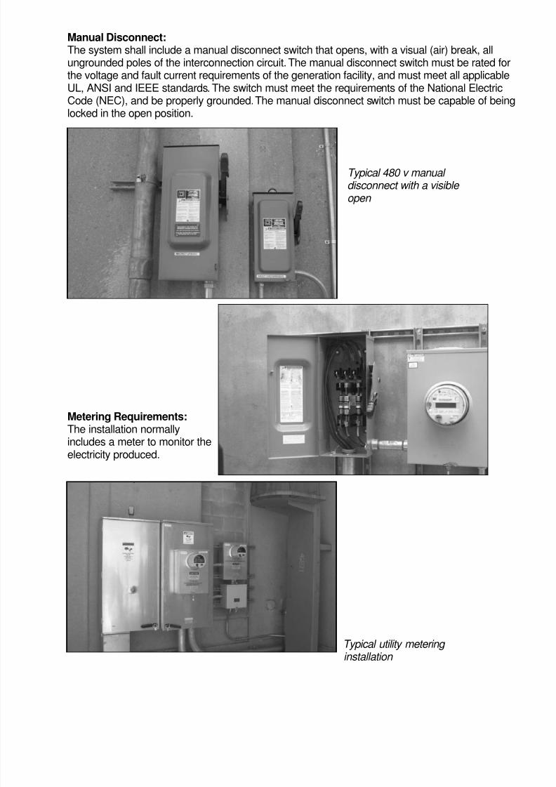
Manual Disconnect:The system shall include a manual disconnect switch that opens, with a visual (air) break, allungrounded poles of the interconnection circuit. The manual disconnect switch must be rated forthe voltage and fault current requirements of the generation facility, and must meet all applicableUL, ANSI and IEEE standards. The switch must meet the requirements of the National ElectricCode (NEC), and be properly grounded.The manual disconnect switch must be capable of beinglocked in the open position.
Metering Requirements:The installation normallyincludes a meter to monitor theelectricity produced.
Typical utility metering installation
Typical 480 v manual disconnect with a visible open

7/27/2019 Introduction to Distributed Generation
http://slidepdf.com/reader/full/introduction-to-distributed-generation 13/21
Grounding:Proper grounding is required between the distributed generation and the distribution system toprovide an adequate fault current path. Grounding practices shall be in conformance with IEEEStd.142-1991.
Islanding:Islanding occurs when distributed generation becomes separated from the main generation
source on a distribution system, yet continues to independently serve a portion of the distributionsystem. Distributed generation must be equipped with protective hardware and/or softwaredesigned to prevent the generator from being connected to a de-energized distribution system.Islanding is not allowed under most guidelines.
Power Quality:Power quality defines the limits of DC injection, voltage flicker, harmonics, immunity protection,and surge capability. The distributed generation should not create system voltage disturbances.
Synchronizing Distributed Generation:The installed equipment must be synchronized with the distribution system.
Automatic Interrupting Device:Distributed generation must include an automatic interrupting device that is listed with a nationallyrecognized testing laboratory, and is rated to interrupt available fault (short circuit) current.Theinterrupting device shall be tripped by any of the required protective functions.
Protection Functions:Protective system requirements for distributed generation are influenced by many factorsincluding:
• Type and size of the power source
• Voltage level of the interconnection
• Location of the distributed generation on the circuit
• Distribution transformer
• Expansion plans of the site
Typical Interrupting Device that is tripped by a protective relays

7/27/2019 Introduction to Distributed Generation
http://slidepdf.com/reader/full/introduction-to-distributed-generation 14/21
• Distribution system configuration
• Available fault current
• Load that can remain connected to the distributed generation under isolated conditions
• Amount of existing distributed generation on the local distribution system.
Protective system requirements can vary. As a result, it is impossible to standardize protectionrequirements strictly according to any single criteria, such as generator size. The specific
protection for each parallel interconnection must be individually determined for each installation.
It is therefore important that the local electric provider must be involved at the earliest possibledate, prior to the purchase of protection equipment, to determine any specific protectionrequirements.
Power Factor:The power factor of the distributed generation interface, as measured at the point of commoncoupling, shall be greater than 0.9 (leading or lagging).
Dedicated Transformer:
Larger distributed generation (typically over 20 kW) may be required to be isolated from othercustomers supplied by the same transformer. This would be accomplished by use of a dedicatedpower transformer connecting to the distribution system. The primary purpose of the dedicatedtransformer is to ensure that (a) the generator cannot become isolated at the secondary voltagelevel with a small amount of other customer's load, and (b) the generator does not contribute anysignificant fault current to other customer's electrical systems. It also helps to block any voltagefluctuation or harmonics produced by the distributed generator
Anti-islanding Test:The anti-islanding test requires that the unit shut down upon sensing the loss of power on thedistribution system.The test is to be conducted with the generation as close to its full output as
possible.
Synchronism Check:This function blocks out-of-phase closing and also prevents closing and energizing a dead lowvoltage bus by the generator.
Under-voltage:This function must be adjustable from 70-90 percent nominal service voltage and have timedelay to override system transients and clearing of external faults. All phase voltages shall bemonitored with an under-voltage relay to provide maximum tripping reliability for three phasegenerators.
Negative Sequence Current:This function should have a long setting time and low voltage pickup setting to detect transformeroverloads due to unbalanced feeder loads.
Over-current:This function serves as the main over current protection and is set to coordinate with thedistributed generation protection and any protection on the local load.
7/27/2019 Introduction to Distributed Generation
http://slidepdf.com/reader/full/introduction-to-distributed-generation 15/21
Over-voltage:This function must be adjustable from 105-120 percent nominal service voltage and have adefinite time delay to override system transients. Phase voltages must be monitored with anover-voltage function to provide maximum tripping reliability for three phase generators.
Under-frequency:An under frequency function with single set point of 59.3 Hz and 10 cycles definite time delayis typical.
Over-frequency:An over-frequency function with a single set point of 60.5 Hz and 10 cycles definite time is typical.
Commissioning and Utility Acceptance Testing of Distributed GenerationBefore parallel operation with the utility system, the installation typically must be witnessed andinspected by the utility. This could include:
• The acceptance testing of all relays according to the utilities minimumrequirements.
• The placement of in-service relay taps according to settings.• The operability of the protective equipment including relays, circuit breakers and
communication channels.
• The phasing and synchronizing checks of all related equipment.
• The anti-islanding test requires that the unit shutdown upon sensing the loss ofpower on the distribution system. Either removing the customer meter or opening adisconnection switch, while the generator is operating, can simulate this.
Type Testing:Type test results must be certified by a nationally recognized test organization. Distributed gener-
ation paralleling equipment that is certified to have met the applicable type testing requirementsof UL1741 (IEEE 929-2000) shall be acceptable for connection to thedistribution system.
Note that interconnection protection is defined at the point of interconnection. Therefore, voltage,frequency and current values used for interconnection protection must be monitored at the pointof interconnection. In some cases, a generator may be located an appreciable distance from thepoint of common coupling.
The use of pre-certified (type tested) paralleling equipment does not automatically qualify thedistributed resource for interconnection to the distribution system at any selected point of inter-
connection. An interconnection review must be performed to determine the compatibility ofthe distributed resource with the distribution system capabilities at the selected point ofinterconnection.
7/27/2019 Introduction to Distributed Generation
http://slidepdf.com/reader/full/introduction-to-distributed-generation 16/21
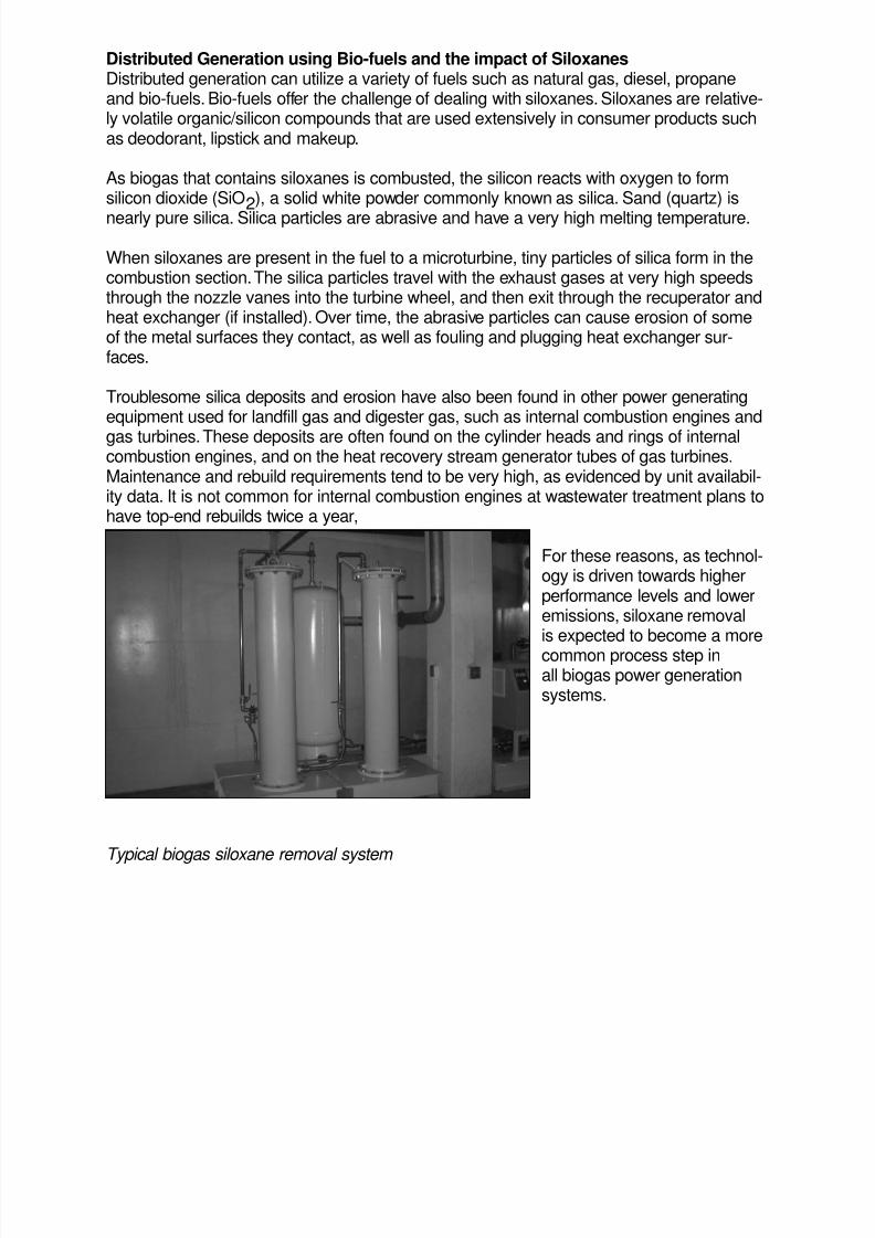
Distributed Generation using Bio-fuels and the impact of SiloxanesDistributed generation can utilize a variety of fuels such as natural gas, diesel, propaneand bio-fuels. Bio-fuels offer the challenge of dealing with siloxanes. Siloxanes are relative-ly volatile organic/silicon compounds that are used extensively in consumer products suchas deodorant, lipstick and makeup.
As biogas that contains siloxanes is combusted, the silicon reacts with oxygen to formsilicon dioxide (SiO2), a solid white powder commonly known as silica. Sand (quartz) is
nearly pure silica. Silica particles are abrasive and have a very high melting temperature.
When siloxanes are present in the fuel to a microturbine, tiny particles of silica form in thecombustion section.The silica particles travel with the exhaust gases at very high speedsthrough the nozzle vanes into the turbine wheel, and then exit through the recuperator andheat exchanger (if installed). Over time, the abrasive particles can cause erosion of someof the metal surfaces they contact, as well as fouling and plugging heat exchanger sur-faces.
Troublesome silica deposits and erosion have also been found in other power generatingequipment used for landfill gas and digester gas, such as internal combustion engines and
gas turbines.These deposits are often found on the cylinder heads and rings of internalcombustion engines, and on the heat recovery stream generator tubes of gas turbines.Maintenance and rebuild requirements tend to be very high, as evidenced by unit availabil-ity data. It is not common for internal combustion engines at wastewater treatment plans tohave top-end rebuilds twice a year,
For these reasons, as technol-ogy is driven towards higherperformance levels and loweremissions, siloxane removalis expected to become a more
common process step inall biogas power generationsystems.
Typical biogas siloxane removal system
7/27/2019 Introduction to Distributed Generation
http://slidepdf.com/reader/full/introduction-to-distributed-generation 17/21
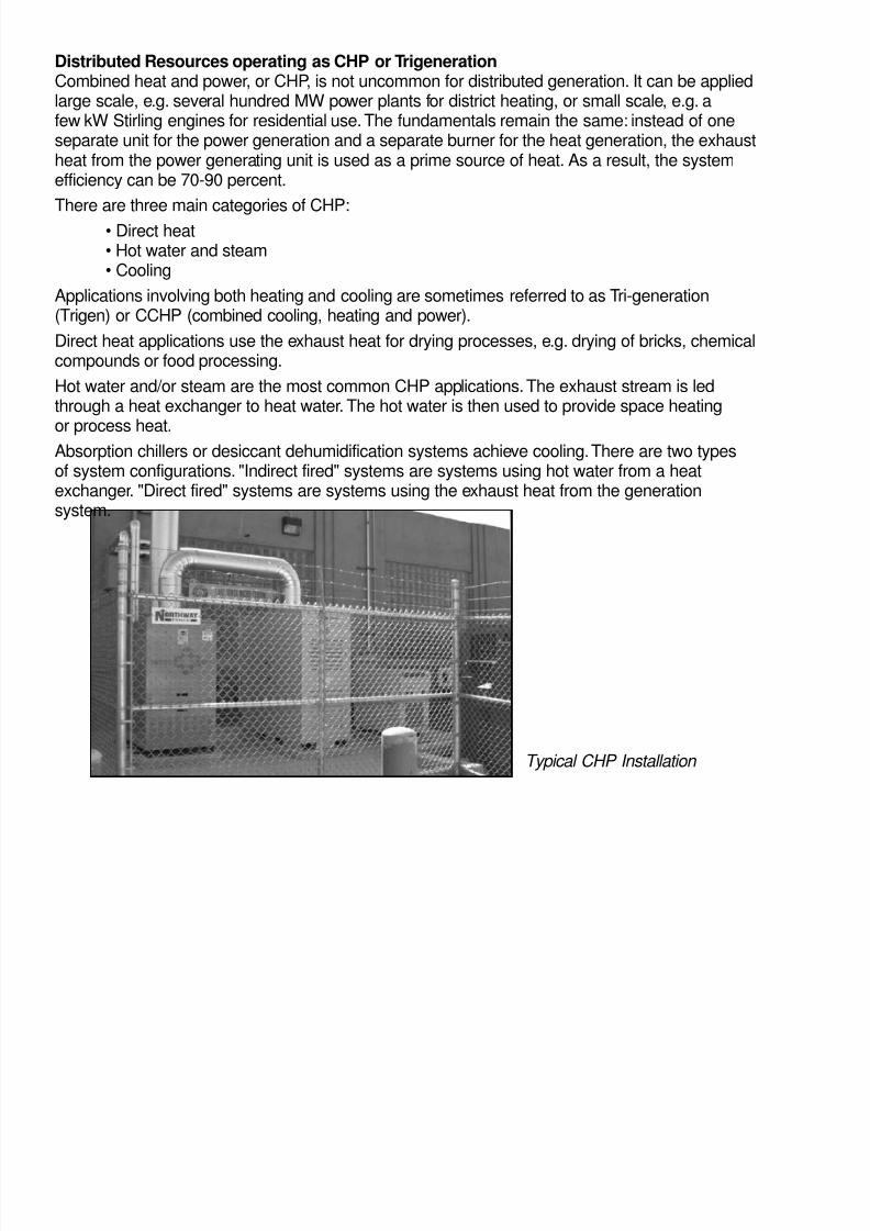
Distributed Resources operating as CHP or TrigenerationCombined heat and power, or CHP, is not uncommon for distributed generation. It can be appliedlarge scale, e.g. several hundred MW power plants for district heating, or small scale, e.g. afew kW Stirling engines for residential use.The fundamentals remain the same: instead of oneseparate unit for the power generation and a separate burner for the heat generation, the exhaustheat from the power generating unit is used as a prime source of heat. As a result, the systemefficiency can be 70-90 percent.
There are three main categories of CHP:
• Direct heat• Hot water and steam• Cooling
Applications involving both heating and cooling are sometimes referred to as Tri-generation(Trigen) or CCHP (combined cooling, heating and power).
Direct heat applications use the exhaust heat for drying processes, e.g. drying of bricks, chemicalcompounds or food processing.
Hot water and/or steam are the most common CHP applications.The exhaust stream is ledthrough a heat exchanger to heat water. The hot water is then used to provide space heating
or process heat.Absorption chillers or desiccant dehumidification systems achieve cooling.There are two typesof system configurations. "Indirect fired" systems are systems using hot water from a heatexchanger. "Direct fired" systems are systems using the exhaust heat from the generationsystem.
Typical CHP Installation

7/27/2019 Introduction to Distributed Generation
http://slidepdf.com/reader/full/introduction-to-distributed-generation 18/21
ConclusionDistributed generation is becoming an increasing important part of the power infrastructure.The advantages of increased power reliability, higher energy efficiency when waste heat isutilized, and the elimination of electric grid transmission and distribution losses, are all driving
the installation of DG. As the number of installations grows, it is important that safety throughthe compliance to all local and national codes remains the key focus of the installation.
Exhaust heat being recovered from
Capstone MicroTurbines
Exhaust heat from MicroTurbines being transferred to hot water in a heat exchanger

7/27/2019 Introduction to Distributed Generation
http://slidepdf.com/reader/full/introduction-to-distributed-generation 19/21
Glossary of Distributed Resource Terms
Aerobic: In the presence of oxygen.
Aerobic Digester: A system used to break down biological wastes by microorganisms in thepresence of oxygen. This method of waste treatment usually has a high-energy input.
AGA: American Gas Association
Anaerobic: In the absence of oxygen
Anaerobic Digester: A container that holds biological wastes, such as manure, in an environ-ment without oxygen. Microorganisms growing in this environment produce methane and otherproducts.
Baseload: The amount of electric power delivered or required continuously.
Biogas: Gas formed from the breakdown of organic material.
Btu: British Thermal Unit. Heating value typically expressed as the amount contained in onecubic foot of a gaseous fuel.
Co-firing: The use of a fuel, other than the principal fuel, to augment of generation of power atthe facility.
Cogeneration: The optimizing of fuel efficiency by generating and utilizing both electrical andthermal energy.
Combustion turbine: See gas turbine.
Digester Gas: A gas containing methane produced from anaerobic digestion of animal or otherorganic wastes.
Distributed Resources (DR): Energy resources that provide either generation, energy storageor demand side management.
Distributed Generation (DG): Small-scale generation that provides electric power at a sitecloser to a customer than a central generation facility. A unit can be connected directly to acustomer's facility or directly to a utility's transmission or distribution system.
Fuel Cell: Energy conversion devices that react hydrogen (H2) or high-quality (hydrogen-rich)
fuels like methane and oxygen into electric current (and heat) without combustion.
Gas Turbine: A rotary engine similar to a jet engine usually fired with natural gas.
Grid: The electric power industry infrastructure of interconnected electrical systems and servicesthat provide power to all users.
IEEE: Institute of Electrical and Electronic Engineers
IEEE 1547: National interconnection standard approved in 2003

7/27/2019 Introduction to Distributed Generation
http://slidepdf.com/reader/full/introduction-to-distributed-generation 20/21
Interconnection: The connection between the distribution line and the customer. Disconnectionand overcurrent protection are required.
Kilowatt (kW): A unit of power equal to 1000 watts or about 1.34 horsepower.
Kilowatt-hour (kWh): A unit of work or energy equal to that expended by one kilowatt in onehour.
Methane: The combustible gas produced by anaerobic digesters. The gas produced by adigester will normally have between 55 percent and 85 percent of the heating value of naturalgas.
Megawatt (MW): One million watts.
Megawatthour (MWh): A unit of work or energy equal to that expanded by one Megawatt in onehour.
Microturbine: A small turbine, similar to a jet engine, capable of operating on a variety ofgaseous and liquid fuels, which is connected to an electric generator.
NEC: United States National Electric Code
NEMA: National Electrical Manufacturers Association
NFPA: National Fire Protection Association
Net Metering: An arrangement where customers can offset their consumption and sell and extraenergy generated at the same rate they pay. The energy quantity is determined by bi-directionalmetering that registers electrical flow in both directions.
Photovoltaic Cell (PV): Converts sunlight directly into electricity with a semiconductor junctionsuch as a diode.
Power Quality (PQ): PQ is the concept of powering and grounding sensitive electronic equip-ment in a manner that is suitable to the operation of that equipment. For retail service, the servicevoltage shall not vary by more than five percent above or below the standard voltage.
Reciprocating Engine: Another name for an internal combustion engine. The engine can bespark of combustion ignition and may use a variety of petroleum or bio based fuels.
Sour-gas: A general term that refers to digester or landfill gases and may also be usedfor some types of petroleum gas. Generally means that the gas contains high levels of hydrogensulfide.
Stirling Engine: An external combustion engine that converts heat from a variety of sources intomechanical energy that can be used to generate electricity.
Substation: A transformer location where the power from transmission lines is stepped down involtage to the distribution lines.

7/27/2019 Introduction to Distributed Generation
http://slidepdf.com/reader/full/introduction-to-distributed-generation 21/21
Transfer Switch: Allows power to flow from only one source, utility or generator, to a load.Eliminates the possibility of a dangerous interconnection.
UPS: Uninterruptible Power Supply. A device that typically uses stored energy to maintaincontinuous delivery of power to a load during a failure of a primary source.
Watt: A unit of power of the rate of doing work (1/746 horsepower).
Wind Turbines: A wind generation system that converts wind power into mechanical power thatis used to generate electric power.
Wind Farm: A group of wind turbines in close proximity.
ReferencesNFPA (National Fire Protection Association)
Contact Information: www.nfpa.orgPH: 617-770-3000
NEC (United States National Electric Code)Contact Information: www.nfpa.org
PH: 617-770-3000
NEMA (National Electrical Manufacturers Association)Contact Information: www.nema.org
PH: 703-841-3200
IEEE (Institute of Electrical and Electronic Engineers)Contact Information: www.ieee.org
PH: 212-419-7900
AGA (American Gas Association)Contact Information: www.aga.com
PH: 202-824-7000