introduction to inroads for photogrammetry to... · training guide. office of design policy &...
TRANSCRIPT

Training Guide
Office of Design Policy & Support
Introduction to InRoads for Photogrammetry
**InRoads Select Series 2**
Developed By Office of Design Policy & Support Product Version InRoads Suite – Select Series 2 Edition
Document Revision Version _1.1 Release Date 07-15-13
Introduction to InRoads- Photogrammetry InRoads Lab SS2 - Revisions
Lab Revisions - 1
Revisions Revision History
Date Revision Number By Section Description 02-01-13 1.00 CB-HC-JB ALL ALL
07-15-13 1.1 CB-HC-JB Lab 1,2 & 7
Revised data import process from AMSA to
import of Photogrammetry
Graphics from DGN File.

Introduction to InRoads- Photogrammetry InRoads Lab SS2 -Table of Contents
Lab Table of Contents - 1
Table of Contents Introduction to InRoads for Photogrammetry Cover ....................................................... Cover Revisions ............................................................................................................... Lab Revisions-1 Introduction .....................................................................................................Lab Introduction-1 Lab 1 Start InRoads and Set Project Defaults ................................................................ Lab 1-1 Lab 2 Create Surface Project............................................................................................ Lab 2-1 Lab 3 Resolving Crossing Segments ................................................................................. Lab 3-1 Lab 4 Create an Exterior Mapping Boundary ................................................................ Lab 4-1 Lab 5 Import the Exterior Boundary............................................................................... Lab 5-1 Lab 6 Resolve DTM Errors ............................................................................................... Lab 6-1 Lab 7 Final Processing of the Mapping Surface ............................................................. Lab 7-1

Introduction to InRoads- Photogrammetry InRoads Lab SS2 - Blank Page
Lab Blank Page - 1
This Page Left Intentionally Blank

Introduction to InRoads- Photogrammetry InRoads Lab SS2- Introduction
Lab Introduction - 1
Introduction Objective Photogrammetry utilizes measurements obtained from aerial photography and stereo plotters to generate digital map data that contains man-made and natural terrain features which are referenced to the State Plane Coordinate System of Georgia. This data is then submitted to Survey Data Engineers as planimetric MicroStation (.DGN) files and topographic 3D mapping Digital Terrain Model (.DTM) files in InRoads. The digital mapping data is used as a database in the development of highway project plans. The objectives of this tutorial are to:
• Create an InRoads Mapping Project to GDOT Standards • Demonstrate the process required to create an InRoads DTM database • Import the 3D photogrammetric DGN data into the database • Process the photogrammetric data in the database • Create/generate the files which are to be submitted as deliverables to the end user
Introduction to InRoads- Photogrammetry InRoads Lab SS2 - Introduction
Lab Introduction - 2
Lab Format Standards In the following labs, user input and action will be displayed in bold type. You will be instructed to either type-in information, click on a command or button, or press a particular key or function button. When instructed to click on something, you will need to press on the left mouse button and then release it. When instructed to double-click, you will need to quickly press the left mouse button twice in rapid succession and then release it. Additionally, the symbol is used to designate successive pull down menus. ie. FileSave. If the lab asks you to press a particular key on the keyboard -- Key strokes will be displayed in < > brackets (ie. <CTRL> or <F4>). The lab format will be as follows: Step Number
The top line will display the instructions or the user input. The user actions will be displayed in the format described above. The bottom line will be in italics and will indicate the system response. It will also display some additional information regarding the process you have just performed.
Note:
Each step of the lab depends on a previous step, so please read everything carefully and DO NOT skip any steps.
InRoads and MicroStation Delineation In the following labs, the user will be working in both the InRoads Design Software and the MicroStation CADD Software. The InRoads Software is the database in which the photogrammetry and surveying data is created and processed. The MicroStation CADD Software is used for the viewing and manipulation of graphics derived from InRoads. In order to differentiate between the two software(s) (so that the user can identify in which software to perform the required steps) the following symbolization will be utilized:
InRoads Software User performs steps in InRoads MicroStation Software User performs steps in MicroStation
Introduction to InRoads- Photogrammetry InRoads SS2 - Lab 1
Lab1-1
Lab 1 Start InRoads and Set Project Defaults
Objective The recommended File Structure for InRoads is a Project Folder (which is named for the PI # of the Project – Example: 1234567) located as a sub-folder under C:\InRoads Data – Example: C:\InRoads Data\1234567). The Project Files are then located in a Photogrammetry sub-folder under the PI # – Example: C:\InRoads Data\1234567\Photogrammetry This Project Folder contains the individual InRoads Data Files. Some Examples of InRoads Data Files are: 1. .DTM ------ (Digital Terrain Model File) – contains Surface data 2. .FWD ------ (Survey File) – contains Field Survey data 3. .ALG------- (Geometry File) – contains Geometric Point, Horizontal and Vertical data 4. .IRD ------- (Roadway Design File) – contains the Design Surface data 5. .RWK------ (Project File) – contains project data for InRoads files in ASCII format 6. .ITL-------- (InRoads Template File) – contains InRoads Templates for cross-sections 7. .SDB------- (Drainage File) – contains the InRoads Storm and Sanitary data
The objective of Lab 1 is to:
• Create a Project Folder • Start InRoads • Set the InRoads Project Defaults • Set Survey Default Preferences • Set the InRoads “Locks” • Add the Application and Variable Manager Add-Ins
It is highly recommended to backup the Project Folder (which contains these individual data files) after each work session to your Group Account on the GDOT Server if you are a GDOT Employee (or to an appropriate Business Server if you are a GDOT Consultant).
Introduction to InRoads- Photogrammetry InRoads SS2 - Lab 1
Lab1-2
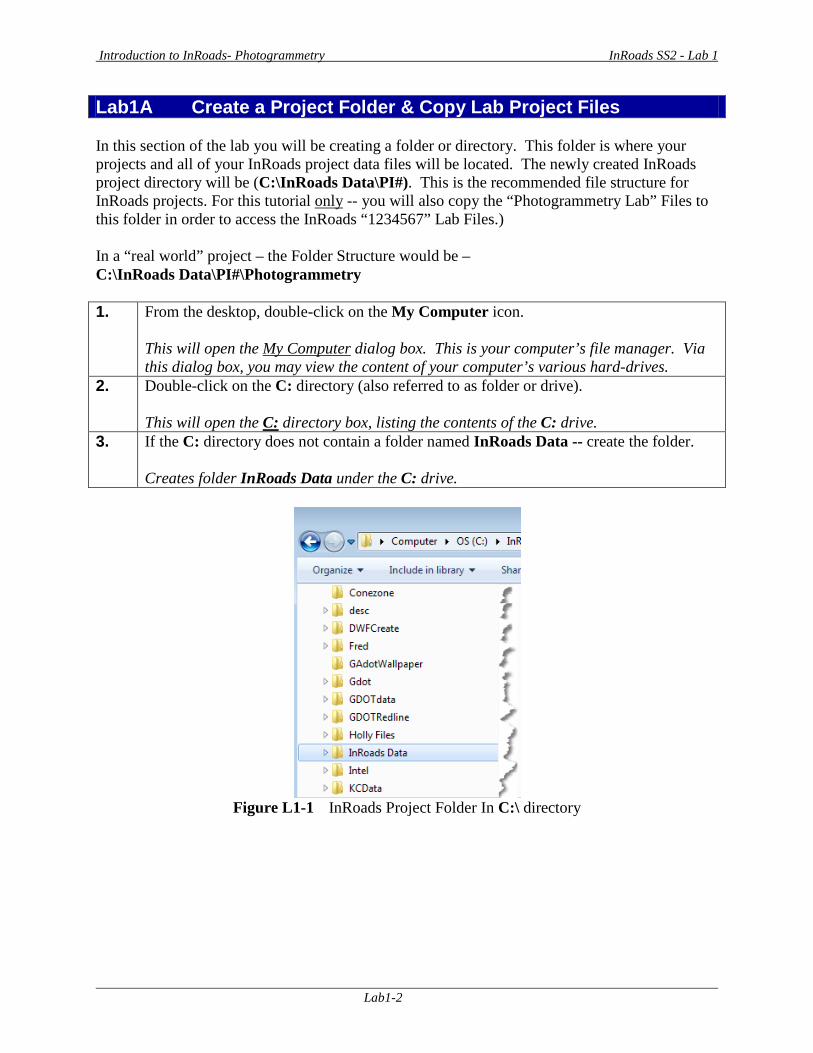
Lab1A Create a Project Folder & Copy Lab Project Files In this section of the lab you will be creating a folder or directory. This folder is where your projects and all of your InRoads project data files will be located. The newly created InRoads project directory will be (C:\InRoads Data\PI#). This is the recommended file structure for InRoads projects. For this tutorial only -- you will also copy the “Photogrammetry Lab” Files to this folder in order to access the InRoads “1234567” Lab Files.) In a “real world” project – the Folder Structure would be – C:\InRoads Data\PI#\Photogrammetry 1. From the desktop, double-click on the My Computer icon.
This will open the My Computer dialog box. This is your computer’s file manager. Via this dialog box, you may view the content of your computer’s various hard-drives.
2. Double-click on the C: directory (also referred to as folder or drive). This will open the C: directory box, listing the contents of the C: drive.
3. If the C: directory does not contain a folder named InRoads Data -- create the folder. Creates folder InRoads Data under the C: drive.
Figure L1-1 InRoads Project Folder In C:\ directory
Introduction to InRoads- Photogrammetry InRoads SS2 - Lab 1
Lab1-3
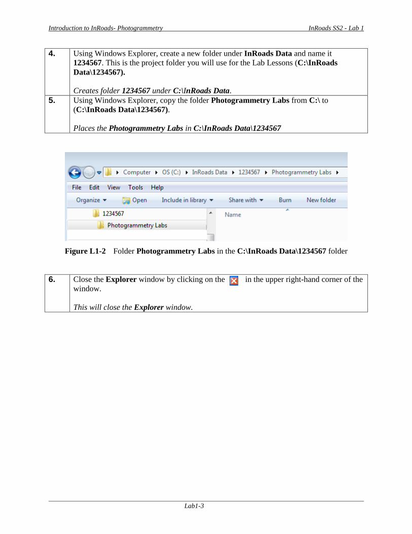
4. Using Windows Explorer, create a new folder under InRoads Data and name it 1234567. This is the project folder you will use for the Lab Lessons (C:\InRoads Data\1234567). Creates folder 1234567 under C:\InRoads Data.
5. Using Windows Explorer, copy the folder Photogrammetry Labs from C:\ to (C:\InRoads Data\1234567). Places the Photogrammetry Labs in C:\InRoads Data\1234567
Figure L1-2 Folder Photogrammetry Labs in the C:\InRoads Data\1234567 folder
6. Close the Explorer window by clicking on the in the upper right-hand corner of the window. This will close the Explorer window.
Introduction to InRoads- Photogrammetry InRoads SS2 - Lab 1
Lab1-4
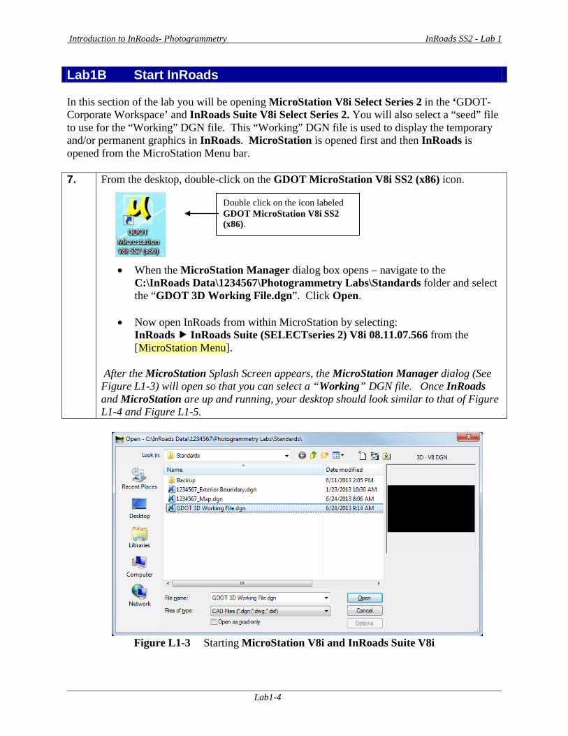
Lab1B Start InRoads In this section of the lab you will be opening MicroStation V8i Select Series 2 in the ‘GDOT-Corporate Workspace’ and InRoads Suite V8i Select Series 2. You will also select a “seed” file to use for the “Working” DGN file. This “Working” DGN file is used to display the temporary and/or permanent graphics in InRoads. MicroStation is opened first and then InRoads is opened from the MicroStation Menu bar. 7. From the desktop, double-click on the GDOT MicroStation V8i SS2 (x86) icon.
• When the MicroStation Manager dialog box opens – navigate to the C:\InRoads Data\1234567\Photogrammetry Labs\Standards folder and select the “GDOT 3D Working File.dgn”. Click Open.
• Now open InRoads from within MicroStation by selecting:
InRoads InRoads Suite (SELECTseries 2) V8i 08.11.07.566 from the [MicroStation Menu].
After the MicroStation Splash Screen appears, the MicroStation Manager dialog (See Figure L1-3) will open so that you can select a “Working” DGN file. Once InRoads and MicroStation are up and running, your desktop should look similar to that of Figure L1-4 and Figure L1-5.
Figure L1-3 Starting MicroStation V8i and InRoads Suite V8i
Double click on the icon labeled GDOT MicroStation V8i SS2 (x86).
Introduction to InRoads- Photogrammetry InRoads SS2 - Lab 1
Lab1-5
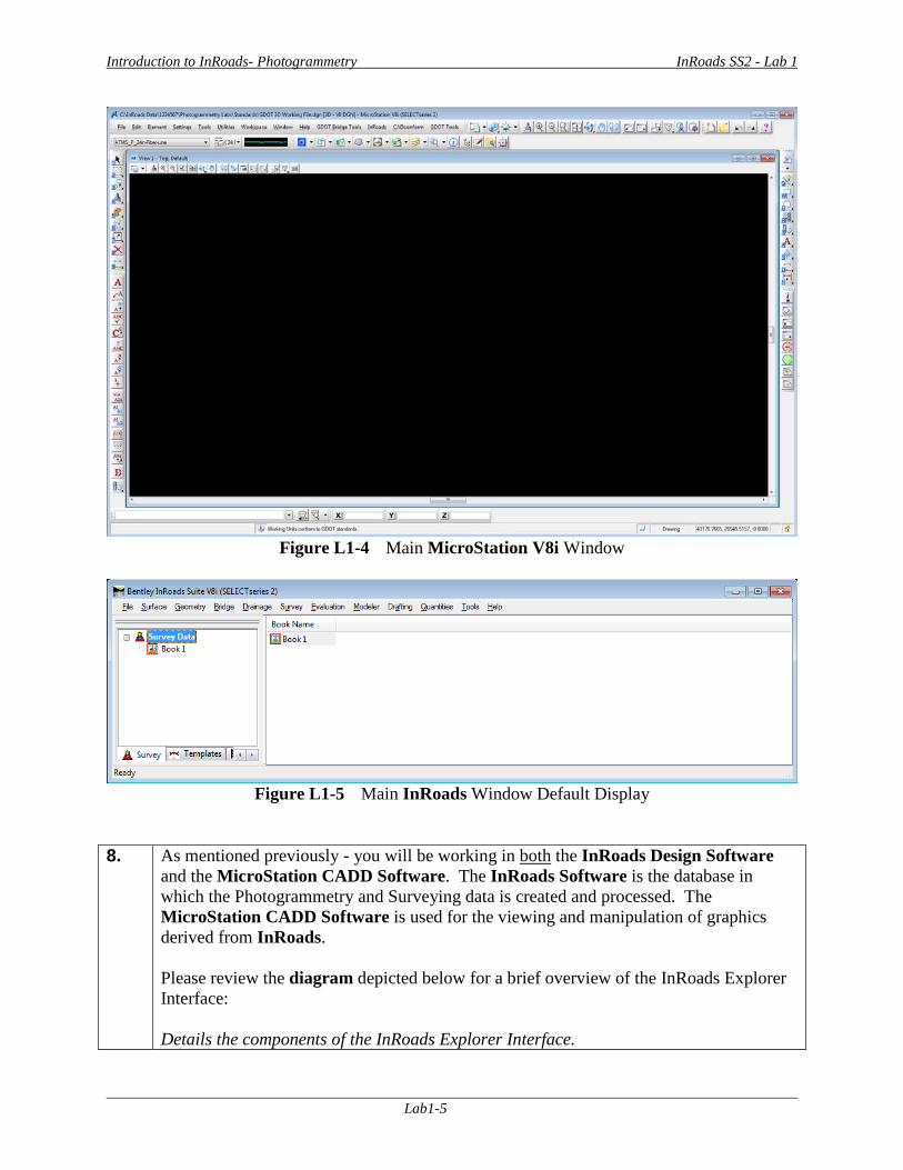
Figure L1-4 Main MicroStation V8i Window
Figure L1-5 Main InRoads Window Default Display
8. As mentioned previously - you will be working in both the InRoads Design Software
and the MicroStation CADD Software. The InRoads Software is the database in which the Photogrammetry and Surveying data is created and processed. The MicroStation CADD Software is used for the viewing and manipulation of graphics derived from InRoads. Please review the diagram depicted below for a brief overview of the InRoads Explorer Interface: Details the components of the InRoads Explorer Interface.
Introduction to InRoads- Photogrammetry InRoads SS2 - Lab 1
Lab1-6
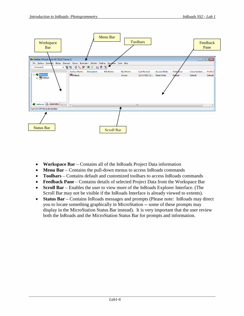
• Workspace Bar – Contains all of the InRoads Project Data information • Menu Bar – Contains the pull-down menus to access InRoads commands • Toolbars – Contains default and customized toolbars to access InRoads commands • Feedback Pane – Contains details of selected Project Data from the Workspace Bar • Scroll Bar – Enables the user to view more of the InRoads Explorer Interface. (The
Scroll Bar may not be visible if the InRoads Interface is already viewed to extents). • Status Bar – Contains InRoads messages and prompts (Please note: InRoads may direct
you to locate something graphically in MicroStation -- some of these prompts may display in the MicroStation Status Bar instead). It is very important that the user review both the InRoads and the MicroStation Status Bar for prompts and information.
Menu Bar Workspace
Bar Feedback
Pane
Status Bar Scroll Bar
Toolbars

Introduction to InRoads- Photogrammetry InRoads SS2 - Lab 1
Lab1-7
Lab1C Set InRoads Project Defaults The InRoads Project Defaults setting allows you to define the “default folder locations” for projects. A Project Default configuration can then be saved for each project so that multiple projects can be accessed. This configuration allows you to easily navigate between projects. Once the Project Folder locations are saved in the Configuration, the projects can then be accessed by selecting the appropriate Project Configuration Name. The Project Defaults also contains the location for selecting the standard GDOT InRoads Preference File (GDOT_Standard V8i_SS2.xin). 9. Click FileProject Defaults from the InRoads pull-down menu.
The Set Project Defaults dialog box appears. Each Project will require an individual setup as detailed in the following steps.
10. Click New and enter 1234567_Mapping in the New Configuration dialog box. Then click OK. The New Configuration dialog box will appear. After entering in the Project Name and clicking OK – a new configuration will be created that is named 1234567_Mapping.
11. Under the Default Preferences section - Click in the Preferences (*.xin): field and then click the Browse button to navigate to the following file: C:\InRoads Data\1234567\Photogrammetry Labs\Standards\GDOT_Standard V8i_SS2.xin. Select the GDOT_Standard V8i_SS2.xin file and click Open. The GDOT_Standard V8i_SS2.xin file is added as the Project Preference File.
12. Under the Default Directory Paths Section - Click in the Project Default Directory: field and then click the Browse button to navigate to the folder: C:\InRoads Data\1234567\Photogrammetry Labs\. Next - click Open. The Current Configuration for the 1234567 project will now default to the following path: C:\InRoads Data\1234567\Photogrammetry Labs.
Introduction to InRoads- Photogrammetry InRoads SS2 - Lab 1
Lab1-8
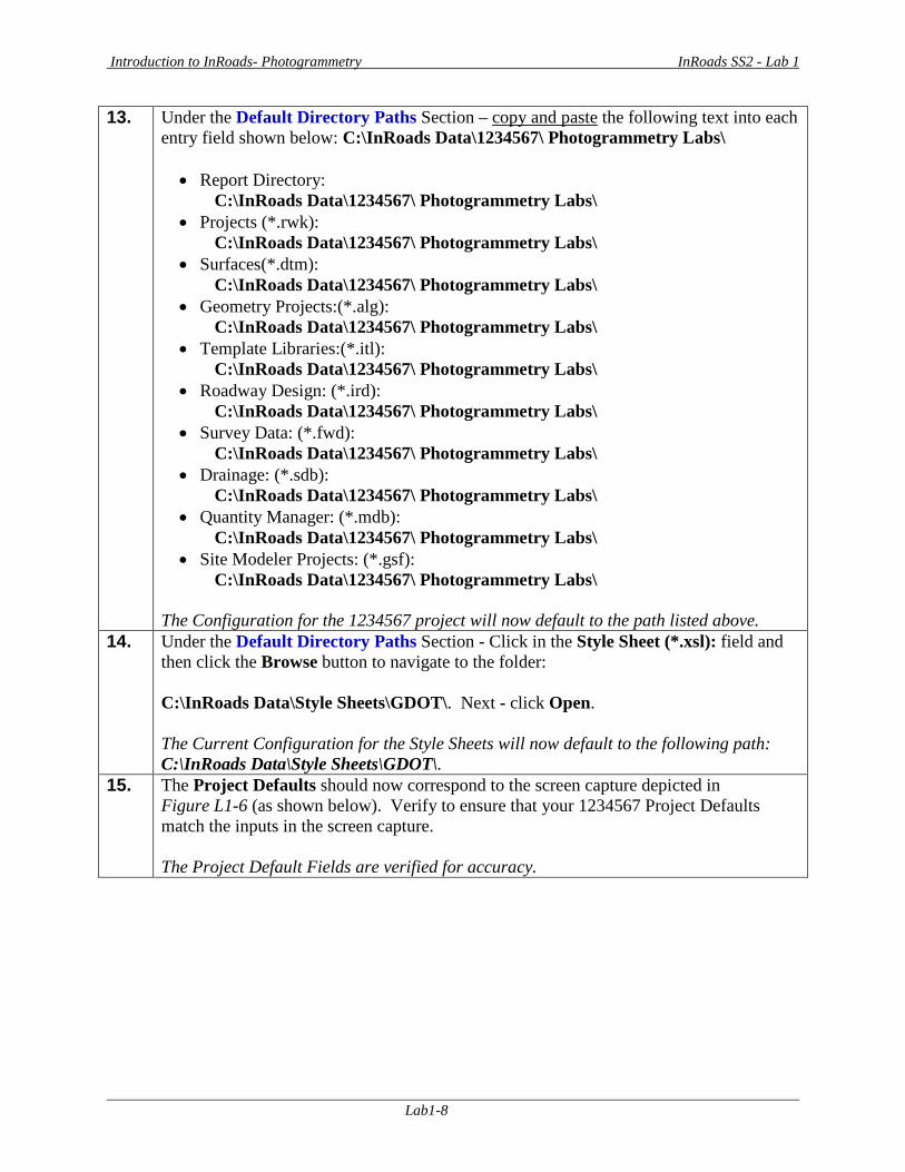
13. Under the Default Directory Paths Section – copy and paste the following text into each entry field shown below: C:\InRoads Data\1234567\ Photogrammetry Labs\ • Report Directory:
C:\InRoads Data\1234567\ Photogrammetry Labs\ • Projects (*.rwk):
C:\InRoads Data\1234567\ Photogrammetry Labs\ • Surfaces(*.dtm):
C:\InRoads Data\1234567\ Photogrammetry Labs\ • Geometry Projects:(*.alg):
C:\InRoads Data\1234567\ Photogrammetry Labs\ • Template Libraries:(*.itl):
C:\InRoads Data\1234567\ Photogrammetry Labs\ • Roadway Design: (*.ird):
C:\InRoads Data\1234567\ Photogrammetry Labs\ • Survey Data: (*.fwd):
C:\InRoads Data\1234567\ Photogrammetry Labs\ • Drainage: (*.sdb):
C:\InRoads Data\1234567\ Photogrammetry Labs\ • Quantity Manager: (*.mdb):
C:\InRoads Data\1234567\ Photogrammetry Labs\ • Site Modeler Projects: (*.gsf):
C:\InRoads Data\1234567\ Photogrammetry Labs\
The Configuration for the 1234567 project will now default to the path listed above. 14. Under the Default Directory Paths Section - Click in the Style Sheet (*.xsl): field and
then click the Browse button to navigate to the folder: C:\InRoads Data\Style Sheets\GDOT\. Next - click Open. The Current Configuration for the Style Sheets will now default to the following path: C:\InRoads Data\Style Sheets\GDOT\.
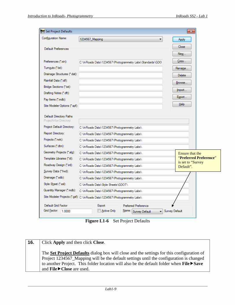
15. The Project Defaults should now correspond to the screen capture depicted in Figure L1-6 (as shown below). Verify to ensure that your 1234567 Project Defaults match the inputs in the screen capture. The Project Default Fields are verified for accuracy.
Introduction to InRoads- Photogrammetry InRoads SS2 - Lab 1
Lab1-9
Figure L1-6 Set Project Defaults
16. Click Apply and then click Close. The Set Project Defaults dialog box will close and the settings for this configuration of Project 1234567_Mapping will be the default settings until the configuration is changed to another Project. This folder location will also be the default folder when FileSave and FileClose are used.
Ensure that the “Preferred Preference” is set to “Survey Default”.
Introduction to InRoads- Photogrammetry InRoads SS2 - Lab 1
Lab1-10
Lab1D Set Survey Default Preferences The Survey Default Preferences must be loaded in InRoads in order to conform to standards for the processing of Mapping Projects. This is a very important step to ensure that standards are followed for any Photogrammetric data that will be processed. The Survey Default Preference loads the Precision Settings, Tolerances, Units and Formats, etc. Once the Survey Default Preference is loaded – the project will retain these settings each time the project is accessed. 17. Click File Project Options from the InRoads pull-down menu to access the Project
Options dialog box. The Project Options dialog box appears.
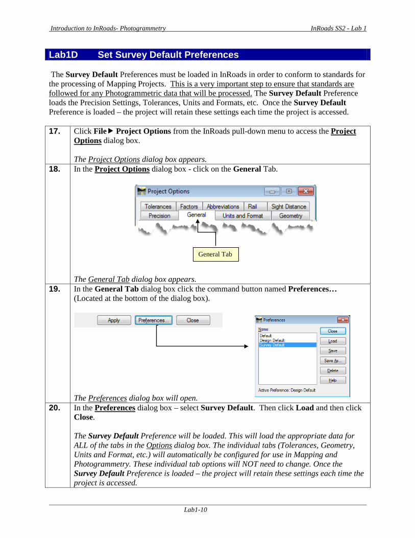
18. In the Project Options dialog box - click on the General Tab.
The General Tab dialog box appears.
19. In the General Tab dialog box click the command button named Preferences… (Located at the bottom of the dialog box).
The Preferences dialog box will open.
20. In the Preferences dialog box – select Survey Default. Then click Load and then click Close. The Survey Default Preference will be loaded. This will load the appropriate data for ALL of the tabs in the Options dialog box. The individual tabs (Tolerances, Geometry, Units and Format, etc.) will automatically be configured for use in Mapping and Photogrammetry. These individual tab options will NOT need to change. Once the Survey Default Preference is loaded – the project will retain these settings each time the project is accessed.
General Tab
Introduction to InRoads- Photogrammetry InRoads SS2 - Lab 1
Lab1-11
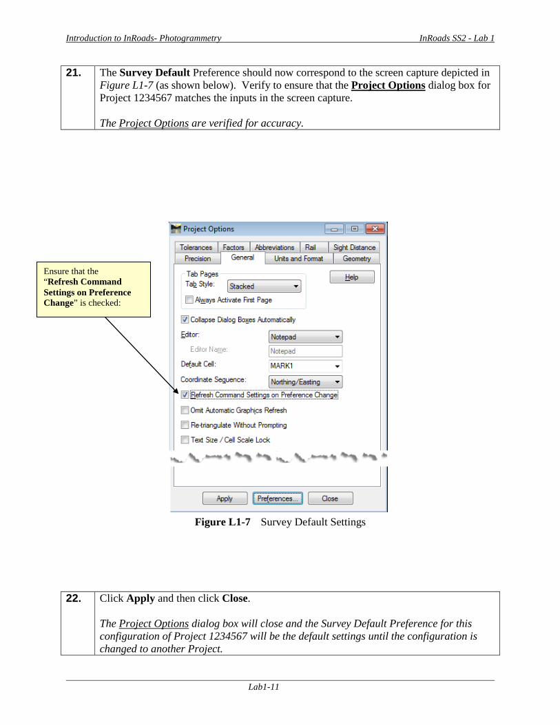
21. The Survey Default Preference should now correspond to the screen capture depicted in Figure L1-7 (as shown below). Verify to ensure that the Project Options dialog box for Project 1234567 matches the inputs in the screen capture. The Project Options are verified for accuracy.
Figure L1-7 Survey Default Settings
22. Click Apply and then click Close. The Project Options dialog box will close and the Survey Default Preference for this configuration of Project 1234567 will be the default settings until the configuration is changed to another Project.
Ensure that the “Refresh Command Settings on Preference Change” is checked:
Introduction to InRoads- Photogrammetry InRoads SS2 - Lab 1
Lab1-12
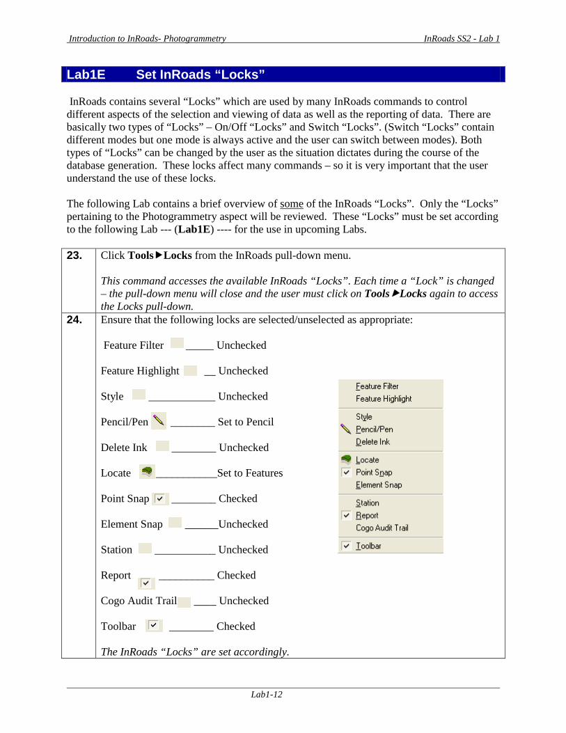
Lab1E Set InRoads “Locks” InRoads contains several “Locks” which are used by many InRoads commands to control different aspects of the selection and viewing of data as well as the reporting of data. There are basically two types of “Locks” – On/Off “Locks” and Switch “Locks”. (Switch “Locks” contain different modes but one mode is always active and the user can switch between modes). Both types of “Locks” can be changed by the user as the situation dictates during the course of the database generation. These locks affect many commands – so it is very important that the user understand the use of these locks. The following Lab contains a brief overview of some of the InRoads “Locks”. Only the “Locks” pertaining to the Photogrammetry aspect will be reviewed. These “Locks” must be set according to the following Lab --- (Lab1E) ---- for the use in upcoming Labs. 23. Click ToolsLocks from the InRoads pull-down menu.
This command accesses the available InRoads “Locks”. Each time a “Lock” is changed – the pull-down menu will close and the user must click on ToolsLocks again to access the Locks pull-down.
24. Ensure that the following locks are selected/unselected as appropriate: Feature Filter _____ Unchecked Feature Highlight __ Unchecked Style ____________ Unchecked Pencil/Pen ________ Set to Pencil Delete Ink ________ Unchecked Locate ___________Set to Features Point Snap ________ Checked Element Snap ______Unchecked Station ___________ Unchecked Report __________ Checked Cogo Audit Trail ____ Unchecked Toolbar ________ Checked The InRoads “Locks” are set accordingly.

Introduction to InRoads- Photogrammetry InRoads SS2 - Lab 1
Lab1-13
25. Following is a brief overview of the “Locks”: Feature Filter displays or obscures Surface Features based on a filter (also controls Survey Style Filter) Feature Highlight highlights the feature in plan view when selected from a list Style determines if a dialog box is displayed for a surface command or cross sections Pencil/Pen controls the redisplaying of Graphics Delete Ink allows redisplayed graphics to replace graphics in pen mode Locate controls if Locate Buttons snaps to Graphics or Features Point Snap controls the ability to snap to points in Geometry Project Element Snap controls the ability to snap to elements in Geometry Project Station controls the Stationing as it pertains to Cross Sections Report controls if Report is displayed or not displayed in a dialog box Cogo Audit Trail controls the reporting of coordinate geometry results to a text file Toolbar displays or turns off the Locks Toolbar Describes a “brief” overview of the InRoads “Locks”.
Introduction to InRoads- Photogrammetry InRoads SS2 - Lab 1
Lab1-14
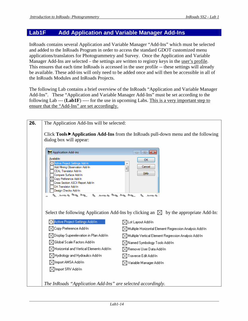
Lab1F Add Application and Variable Manager Add-Ins InRoads contains several Application and Variable Manager “Add-Ins” which must be selected and added to the InRoads Program in order to access the standard GDOT customized menu applications/translators for Photogrammetry and Survey. Once the Application and Variable Manager Add-Ins are selected – the settings are written to registry keys in the user’s profile. This ensures that each time InRoads is accessed in the user profile -- these settings will already be available. These add-ins will only need to be added once and will then be accessible in all of the InRoads Modules and InRoads Projects. The following Lab contains a brief overview of the InRoads “Application and Variable Manager Add-Ins”. These “Application and Variable Manager Add-Ins” must be set according to the following Lab --- (Lab1F) ---- for the use in upcoming Labs. This is a very important step to ensure that the “Add-Ins” are set accordingly. 26. The Application Add-Ins will be selected:
Click ToolsApplication Add-Ins from the InRoads pull-down menu and the following dialog box will appear:
Select the following Application Add-Ins by clicking an by the appropriate Add-In:
The InRoads “Application Add-Ins” are selected accordingly.
Introduction to InRoads- Photogrammetry InRoads SS2 - Lab 1
Lab1-15
27. Click OK to accept the settings and to close out of the dialog box. The Application Add-Ins dialog box will close and the selected Application Add-Ins will be available for use.
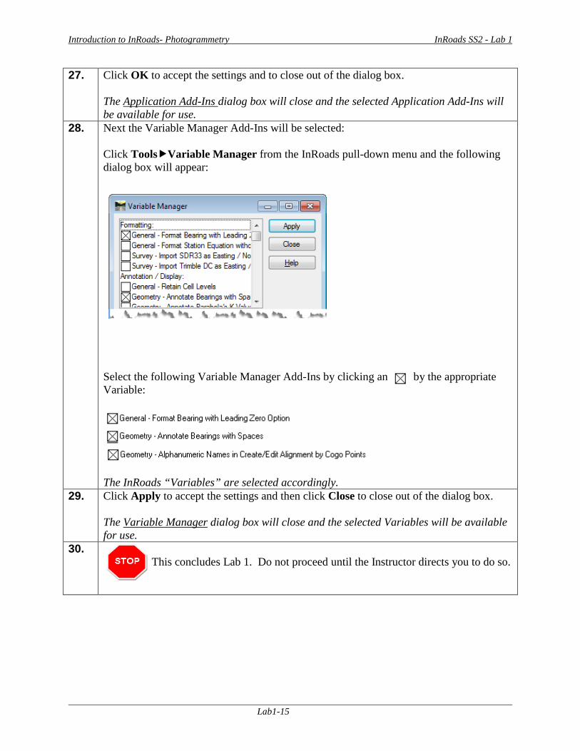
28. Next the Variable Manager Add-Ins will be selected: Click ToolsVariable Manager from the InRoads pull-down menu and the following dialog box will appear:
Select the following Variable Manager Add-Ins by clicking an by the appropriate Variable:
The InRoads “Variables” are selected accordingly.
29. Click Apply to accept the settings and then click Close to close out of the dialog box. The Variable Manager dialog box will close and the selected Variables will be available for use.
30. This concludes Lab 1. Do not proceed until the Instructor directs you to do so.

Introduction to InRoads - Photogrammetry InRoads SS2 – Lab 2
Lab2-1
Lab 2 Create Surface Project and Import
Mapping Data from MicroStation DGN File Objective An InRoads Surface Project (.DTM File) must be created and must be active in order to import in the Mapping Data from a MicroStation DGN File. In this tutorial, Project 1234567_Map.dtm (Surface File) will be created. This active database will be used to import, generate and process the Mapping data from Photogrammetry. InRoads contains an ImportSurface Advanced command which imports the Photogrammetric Data in the MicroStation DGN file into a format that is usable for InRoads. The Surface Advanced command imports the 3D DGN elements into InRoads based on the Level of the Features in MicroStation as well as the Level and Cell for Random Terrain Points. The 2D planimetric DGN elements are not imported into InRoads from the DGN file. After the elements are imported into InRoads as Surface Features, these Features are then processed and triangulated. The processing and triangulating of the Surface Data will be discussed in more detail in later Labs. The objective of Lab 2 is to:
• Create a Surface Database Project (Project 1234567_Map.dtm) • Save the Surface Database Project (Project 1234567_Map.dtm) • Import the Photogrammetric Elements from a MicroStation 3D DGN File
Introduction to InRoads - Photogrammetry InRoads SS2 – Lab 2
Lab2-2
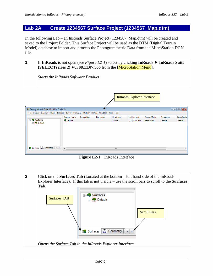
Lab 2A Create 1234567 Surface Project (1234567_Map.dtm) In the following Lab – an InRoads Surface Project (1234567_Map.dtm) will be created and saved to the Project Folder. This Surface Project will be used as the DTM (Digital Terrain Model) database to import and process the Photogrammetric Data from the MicroStation DGN file. 1. If InRoads is not open (see Figure L2-1) select by clicking InRoads InRoads Suite
(SELECTseries 2) V8i 08.11.07.566 from the [MicroStation Menu]. Starts the InRoads Software Product.
Figure L2-1 InRoads Interface
2. Click on the Surfaces Tab (Located at the bottom – left hand side of the InRoads Explorer Interface). If this tab is not visible – use the scroll bars to scroll to the Surfaces Tab. Opens the Surface Tab in the InRoads Explorer Interface.
InRoads Explorer Interface
Surfaces TAB
Scroll Bars
Introduction to InRoads - Photogrammetry InRoads SS2 – Lab 2
Lab2-3
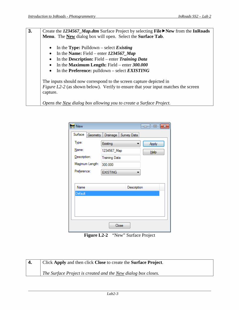
3. Create the 1234567_Map.dtm Surface Project by selecting FileNew from the InRoads Menu. The New dialog box will open. Select the Surface Tab.
• In the Type: Pulldown – select Existing • In the Name: Field – enter 1234567_Map • In the Description: Field – enter Training Data • In the Maximum Length: Field – enter 300.000 • In the Preference: pulldown – select EXISTING
The inputs should now correspond to the screen capture depicted in Figure L2-2 (as shown below). Verify to ensure that your input matches the screen capture. Opens the New dialog box allowing you to create a Surface Project.
Figure L2-2 “New” Surface Project
4. Click Apply and then click Close to create the Surface Project.
The Surface Project is created and the New dialog box closes.
Introduction to InRoads - Photogrammetry InRoads SS2 – Lab 2
Lab2-4
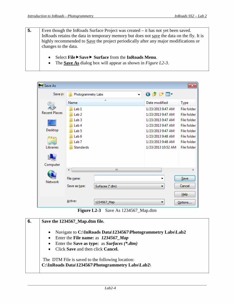
5. Even though the InRoads Surface Project was created – it has not yet been saved. InRoads retains the data in temporary memory but does not save the data on the fly. It is highly recommended to Save the project periodically after any major modifications or changes to the data.
• Select FileSave Surface from the InRoads Menu. • The Save As dialog box will appear as shown in Figure L2-3.
Figure L2-3 Save As 1234567_Map.dtm
6. Save the 1234567_Map.dtm file.
• Navigate to C:\InRoads Data\1234567\Photogrammetry Labs\Lab2 • Enter the File name: as 1234567_Map • Enter the Save as type: as Surfaces (*.dtm) • Click Save and then click Cancel.
The DTM File is saved to the following location: C:\InRoads Data\1234567\Photogrammetry Labs\Lab2\
Introduction to InRoads - Photogrammetry InRoads SS2 – Lab 2
Lab2-5
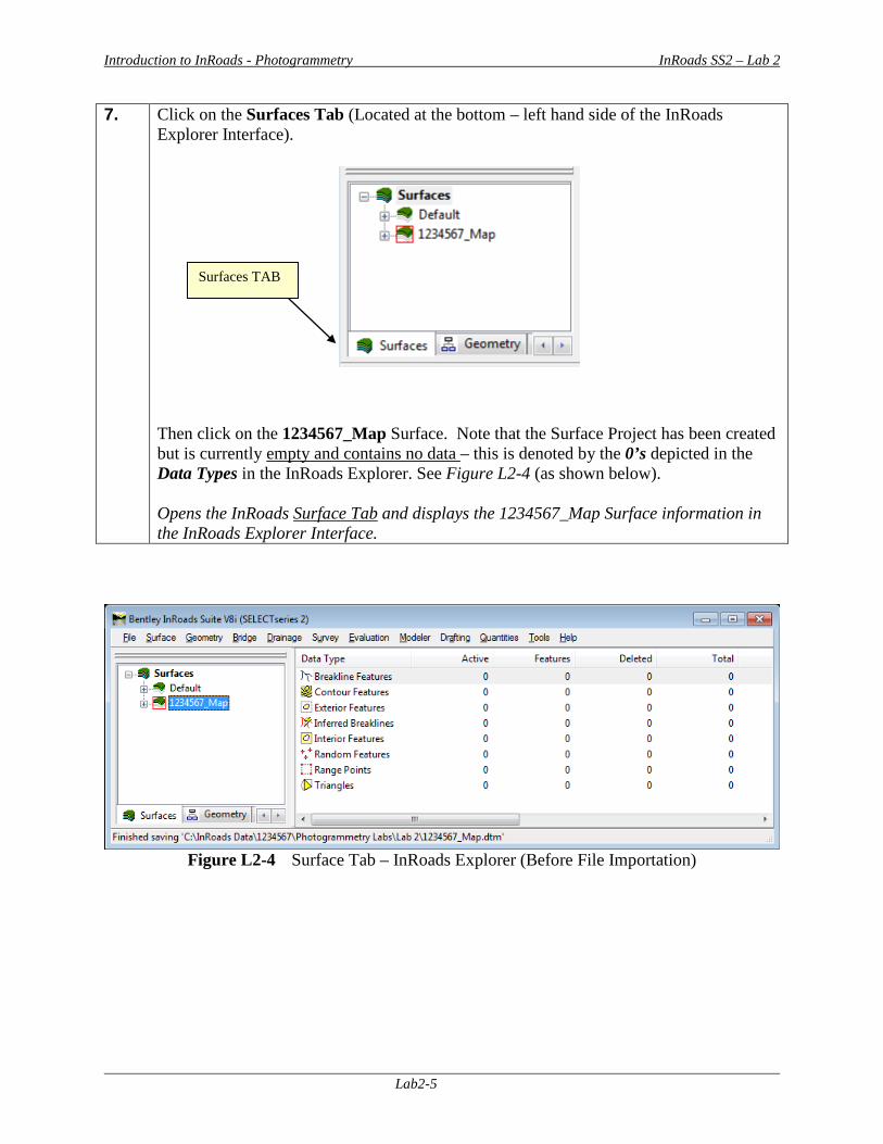
7. Click on the Surfaces Tab (Located at the bottom – left hand side of the InRoads Explorer Interface). Then click on the 1234567_Map Surface. Note that the Surface Project has been created but is currently empty and contains no data – this is denoted by the 0’s depicted in the Data Types in the InRoads Explorer. See Figure L2-4 (as shown below). Opens the InRoads Surface Tab and displays the 1234567_Map Surface information in the InRoads Explorer Interface.
Figure L2-4 Surface Tab – InRoads Explorer (Before File Importation)
Surfaces TAB
Introduction to InRoads - Photogrammetry InRoads SS2 – Lab 2
Lab2-6
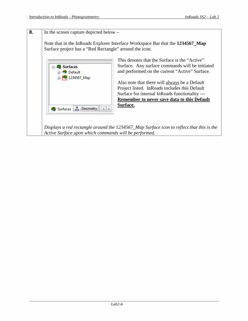
8. In the screen capture depicted below – Note that in the InRoads Explorer Interface Workspace Bar that the 1234567_Map Surface project has a “Red Rectangle” around the icon.
This denotes that the Surface is the “Active” Surface. Any surface commands will be initiated and performed on the current “Active” Surface. Also note that there will always be a Default Project listed. InRoads includes this Default Surface for internal InRoads functionality --- Remember to never save data to this Default Surface.
Displays a red rectangle around the 1234567_Map Surface icon to reflect that this is the Active Surface upon which commands will be performed.
Introduction to InRoads - Photogrammetry InRoads SS2 – Lab 2
Lab2-7
Lab 2B Import Mapping Data from the MicroStation DGN File In the following Lab – the 3D Photogrammetric Data from the Mapping DGN file will be imported into the 1234567_Map.dtm database by using the InRoads FileImportSurface Advanced command. After the DGN Data has been imported – the Surface Features will be saved to the 1234567_Map.dtm Surface Project. **Please Note:**
• In the following steps, you will be opening the 1234567_Map.dgn file. This is the file that is generated from Softcopy and contains both the 2D and 3D Photogrammetric DGN elements. Only the 3D elements will be imported into InRoads from this DGN file.
• Also, please ensure that you do not delete any elements in this DGN!! This is the original
DGN Mapping file that is generated from Softcopy. If the Data in this DGN file is ever deleted, the data will then have to be regenerated from the Mapping Software. Only delete data from the GDOT 3D Working File.dgn.
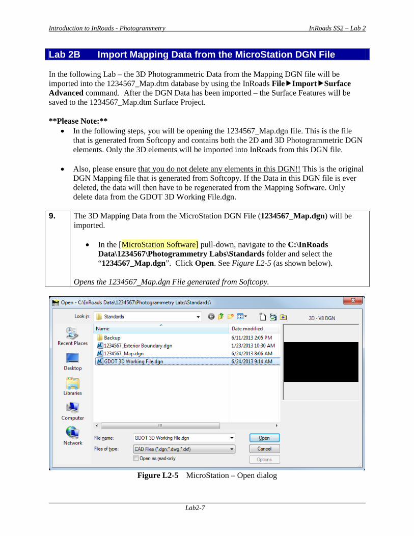
9. The 3D Mapping Data from the MicroStation DGN File (1234567_Map.dgn) will be
imported.
• In the [MicroStation Software] pull-down, navigate to the C:\InRoads Data\1234567\Photogrammetry Labs\Standards folder and select the “1234567_Map.dgn”. Click Open. See Figure L2-5 (as shown below).
Opens the 1234567_Map.dgn File generated from Softcopy.
Figure L2-5 MicroStation – Open dialog
Introduction to InRoads - Photogrammetry InRoads SS2 – Lab 2
Lab2-8
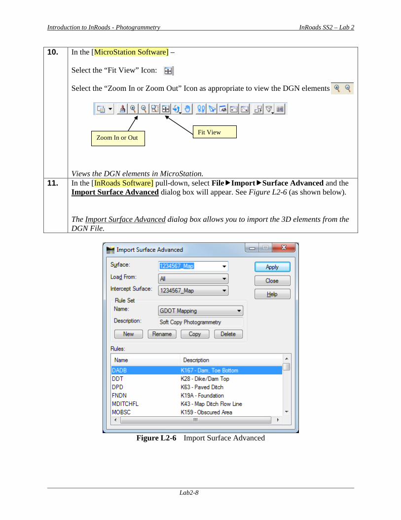
10. In the [MicroStation Software] – Select the “Fit View” Icon: Select the “Zoom In or Zoom Out” Icon as appropriate to view the DGN elements
Views the DGN elements in MicroStation.
11. In the [InRoads Software] pull-down, select FileImportSurface Advanced and the Import Surface Advanced dialog box will appear. See Figure L2-6 (as shown below). The Import Surface Advanced dialog box allows you to import the 3D elements from the DGN File.
Figure L2-6 Import Surface Advanced
Fit View Zoom In or Out
Introduction to InRoads - Photogrammetry InRoads SS2 – Lab 2
Lab2-9
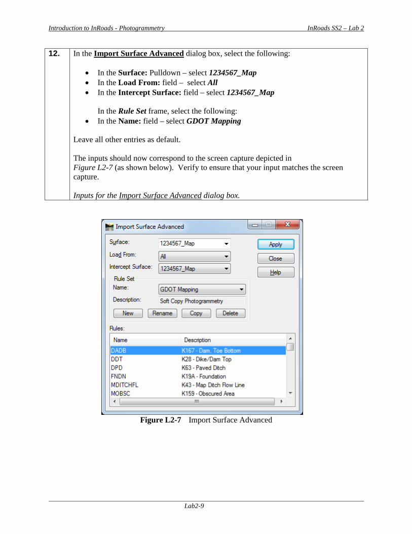
12. In the Import Surface Advanced dialog box, select the following:
• In the Surface: Pulldown – select 1234567_Map • In the Load From: field – select All • In the Intercept Surface: field – select 1234567_Map
In the Rule Set frame, select the following:
• In the Name: field – select GDOT Mapping Leave all other entries as default. The inputs should now correspond to the screen capture depicted in Figure L2-7 (as shown below). Verify to ensure that your input matches the screen capture. Inputs for the Import Surface Advanced dialog box.
Figure L2-7 Import Surface Advanced
Introduction to InRoads - Photogrammetry InRoads SS2 – Lab 2
Lab2-10
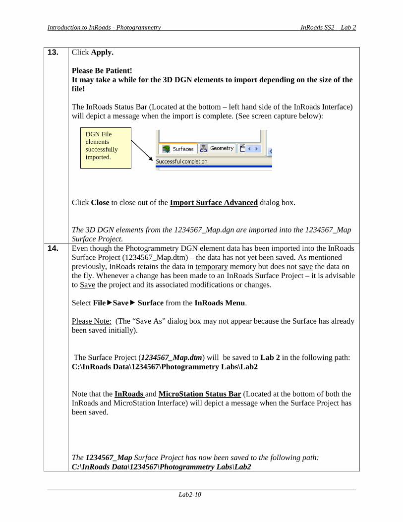
13. Click Apply. Please Be Patient! It may take a while for the 3D DGN elements to import depending on the size of the file! The InRoads Status Bar (Located at the bottom – left hand side of the InRoads Interface) will depict a message when the import is complete. (See screen capture below):
Click Close to close out of the Import Surface Advanced dialog box. The 3D DGN elements from the 1234567_Map.dgn are imported into the 1234567_Map Surface Project.
14. Even though the Photogrammetry DGN element data has been imported into the InRoads Surface Project (1234567_Map.dtm) – the data has not yet been saved. As mentioned previously, InRoads retains the data in temporary memory but does not save the data on the fly. Whenever a change has been made to an InRoads Surface Project – it is advisable to Save the project and its associated modifications or changes. Select FileSave Surface from the InRoads Menu. Please Note: (The “Save As” dialog box may not appear because the Surface has already been saved initially). The Surface Project (1234567_Map.dtm) will be saved to Lab 2 in the following path: C:\InRoads Data\1234567\Photogrammetry Labs\Lab2 Note that the InRoads and MicroStation Status Bar (Located at the bottom of both the InRoads and MicroStation Interface) will depict a message when the Surface Project has been saved. The 1234567_Map Surface Project has now been saved to the following path: C:\InRoads Data\1234567\Photogrammetry Labs\Lab2
DGN File elements successfully imported.
Introduction to InRoads - Photogrammetry InRoads SS2 – Lab 2
Lab2-11
15. IMPORTANT!! As mentioned previously, the 1234567_Map.dgn file which is generated from Softcopy should only be used to import the DGN elements into InRoads. After importing the data into InRoads, you will need to close out of this 1234567_Map DGN file and re-open the GDOT 3D Working File.dgn to perform any additional work in InRoads. If data is inadvertently deleted from the 1234567_Map.dgn, the data will then have to be regenerated from the Mapping Software. Only delete data from the GDOT 3D Working File.dgn.
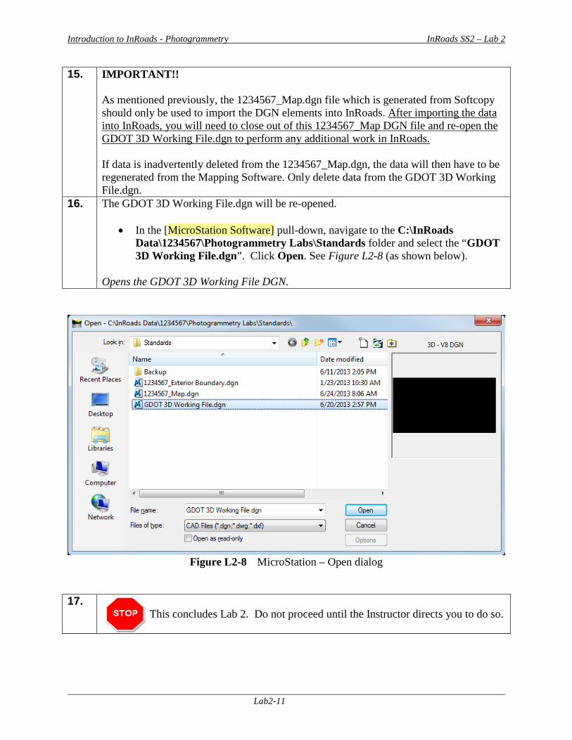
16. The GDOT 3D Working File.dgn will be re-opened.
• In the [MicroStation Software] pull-down, navigate to the C:\InRoads Data\1234567\Photogrammetry Labs\Standards folder and select the “GDOT 3D Working File.dgn”. Click Open. See Figure L2-8 (as shown below).
Opens the GDOT 3D Working File DGN.
Figure L2-8 MicroStation – Open dialog
17.
This concludes Lab 2. Do not proceed until the Instructor directs you to do so.


Introduction to InRoads - Photogrammetry InRoads SS2 – Lab 3
Lab3-1
Lab 3 Resolving Crossing Segments
Objective During the processing of the Photogrammetry data, situations can occur where breaklines may overlap or breaklines may cross at mismatched elevations. If these segment crossings are not resolved, erroneous point and breakline data may affect the triangulation and accuracy of the DTM (Digital Terrain Model). These crossings need to be addressed and resolved prior to the final creation of the DTM Surface to ensure that an accurate Surface Model is generated. A Surface must first be triangulated in order to resolve crossing segments. This is a preliminary triangulation only – the final creation and processing of the Existing DTM Surface will be discussed in later Labs. InRoads contains a View Crossing Segments command which not only views the crossing and/or overlaps but also generates a Crossing Segments report. InRoads also contains a Resolve Crossing Segments command which is an automated tool which can assist in the repairing of crossing and overlapping segments that have small differences in elevation. There are several tools and methods in InRoads to resolve crossing segments and mismatched elevations. The following Lab depicts one method of resolving this issue. The objective of Lab 3 is to:
• Create a “Preliminary” triangulated Surface to check for crossing segments • Utilize the View Crossing Segments command to determine the location of crossing
segments • Utilize the Resolve Crossing Segments command to assist in the resolution of
crossing segments
Introduction to InRoads - Photogrammetry InRoads SS2 – Lab 3
Lab3-2
Lab3A Create a “Preliminary” Triangulated Surface In this section of the lab you will be creating a “Preliminary” triangulated surface which will be utilized in resolving crossing breaklines. A triangulated surface must first exist in order to use the Crossing Segments commands. 1. Starting Clean
In order to ensure that you are working with a “clean” database – you will close MicroStation and InRoads if they are still running from a previous Lab: To CLOSE MicroStation and InRoads - Select FileExit from the [MicroStation Menu]. If any messages appear regarding the saving of projects – Select This closes BOTH the MicroStation and InRoads Software(s).
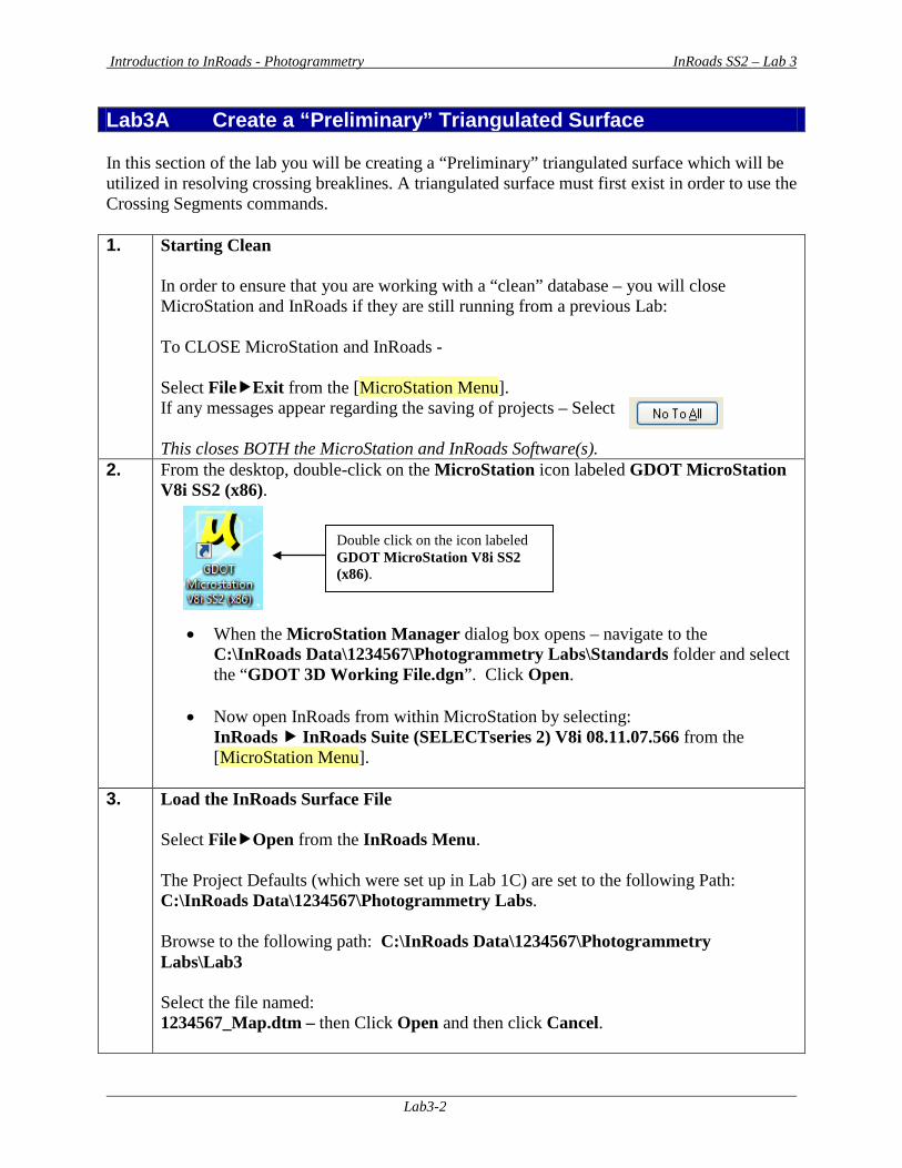
2. From the desktop, double-click on the MicroStation icon labeled GDOT MicroStation V8i SS2 (x86).
• When the MicroStation Manager dialog box opens – navigate to the C:\InRoads Data\1234567\Photogrammetry Labs\Standards folder and select the “GDOT 3D Working File.dgn”. Click Open.
• Now open InRoads from within MicroStation by selecting:
InRoads InRoads Suite (SELECTseries 2) V8i 08.11.07.566 from the [MicroStation Menu].
3. Load the InRoads Surface File
Select FileOpen from the InRoads Menu. The Project Defaults (which were set up in Lab 1C) are set to the following Path: C:\InRoads Data\1234567\Photogrammetry Labs. Browse to the following path: C:\InRoads Data\1234567\Photogrammetry Labs\Lab3 Select the file named: 1234567_Map.dtm – then Click Open and then click Cancel.
Double click on the icon labeled GDOT MicroStation V8i SS2 (x86).
Introduction to InRoads - Photogrammetry InRoads SS2 – Lab 3
Lab3-3
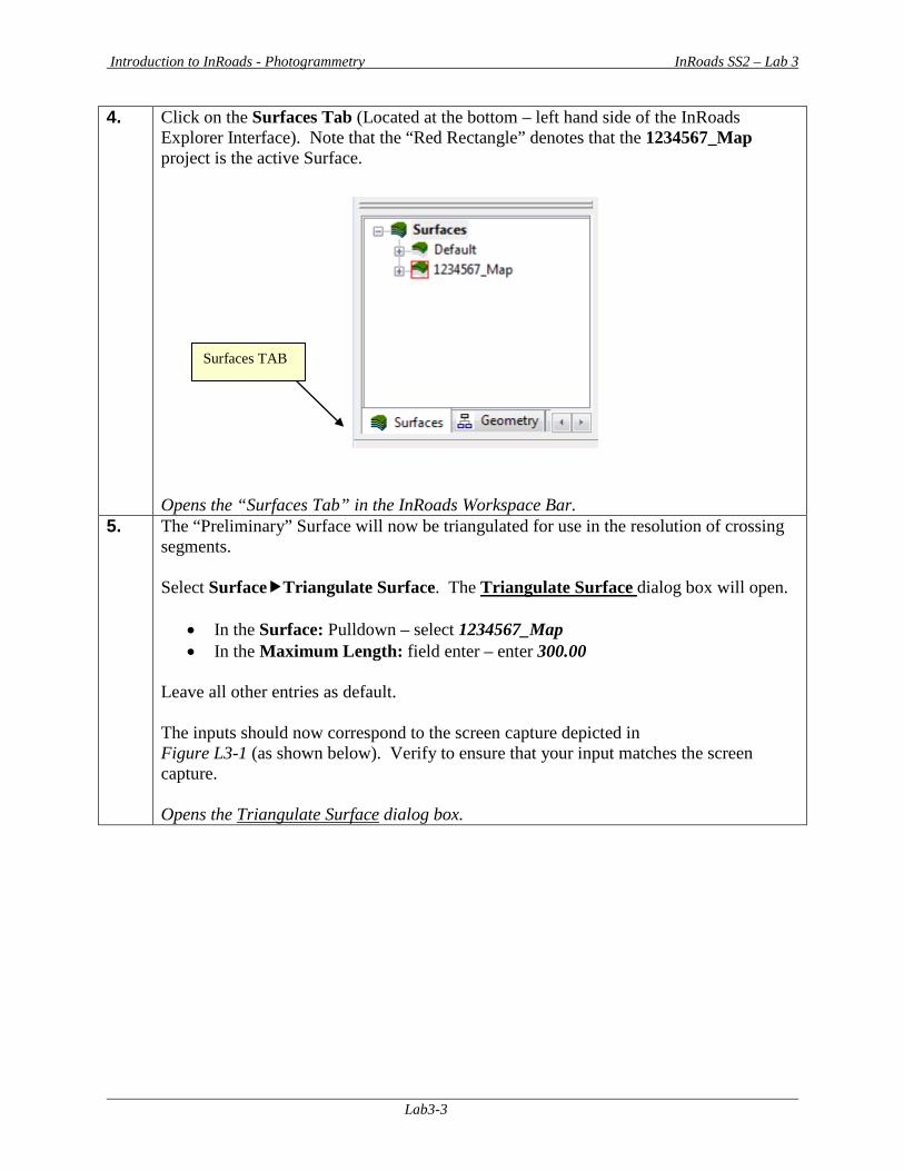
4. Click on the Surfaces Tab (Located at the bottom – left hand side of the InRoads Explorer Interface). Note that the “Red Rectangle” denotes that the 1234567_Map project is the active Surface. Opens the “Surfaces Tab” in the InRoads Workspace Bar.
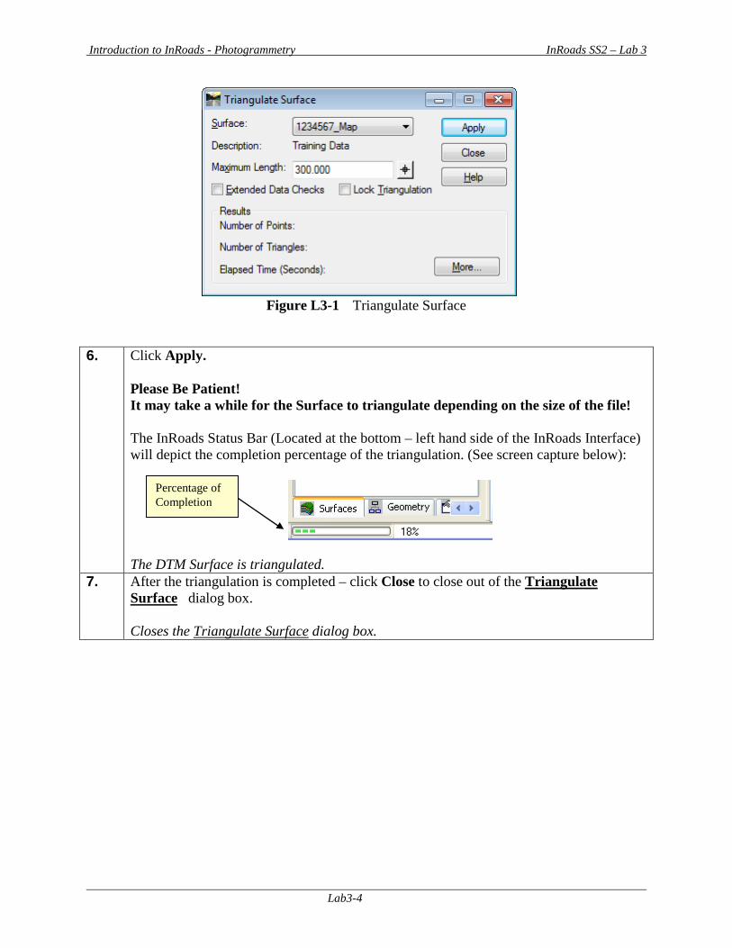
5. The “Preliminary” Surface will now be triangulated for use in the resolution of crossing segments. Select SurfaceTriangulate Surface. The Triangulate Surface dialog box will open.
• In the Surface: Pulldown – select 1234567_Map • In the Maximum Length: field enter – enter 300.00
Leave all other entries as default. The inputs should now correspond to the screen capture depicted in Figure L3-1 (as shown below). Verify to ensure that your input matches the screen capture. Opens the Triangulate Surface dialog box.
Surfaces TAB
Introduction to InRoads - Photogrammetry InRoads SS2 – Lab 3
Lab3-4
Figure L3-1 Triangulate Surface
6. Click Apply.
Please Be Patient! It may take a while for the Surface to triangulate depending on the size of the file! The InRoads Status Bar (Located at the bottom – left hand side of the InRoads Interface) will depict the completion percentage of the triangulation. (See screen capture below):
The DTM Surface is triangulated.
7. After the triangulation is completed – click Close to close out of the Triangulate Surface dialog box. Closes the Triangulate Surface dialog box.
Percentage of Completion
Introduction to InRoads - Photogrammetry InRoads SS2 – Lab 3
Lab3-5
Lab3B View Crossing Segments In the following Labs, the View Crossing Segments and the Resolve Crossing Segments commands will be used to eliminate certain segment crossings. (NOTE: Not all segment crossings will be resolved in this Lab.) The View Crossing Segments command requires a surface to be triangulated before using this utility. This utility can be used -- not only for the viewing of the crossing segments -- but also to generate a Report detailing information of the crossing segments. When using the View Crossing Segments command -- crossing segment points are represented by a Yellow X. Mismatched elevations are represented by a Red O. Basically there are two main types of crossing segments: overlaps and mismatched elevations. Overlaps: InRoads has a basic rule that the longest segment of two overlaps is dominant. Based on this rule InRoads automatically “ignores” the shorter segment during the triangulation process and triangulates according to the dominant breakline. The resolution of these overlaps is determined during the triangulation process. The Segment Crossings which have been resolved during the triangulation are represented by (a Yellow X). These segment crossings with (a Yellow X) can be ignored. Mismatched Elevations: Mismatched elevations occur when crossing breaklines have the same XY Coordinate but different elevations (Z). Minimal elevation differences (any elevation difference less than 0.020) can be repaired using the InRoads Resolve Crossing Segments command (Automatic Option). Any elevation differences that are greater than 0.020 must be manually repaired by using the InRoads Resolve Crossing Segments (Interactive Option). If a specific elevation needs to be modified to correct the crossing segment – the Surface Edit Feature Points command may be used. The Mismatched Elevations are represented by (a Red O). These must be resolved to ensure an accurate surface. The View Crossing Segments command is used to assist in determining the location of segment crossing points – both visually and in Report format. 8. Click ToolsLocks from the InRoads pull-down menu. Ensure that the Style Lock is
turned off. There should not be a check mark next to the Style Lock. Ensures that the Style Lock is turned off.
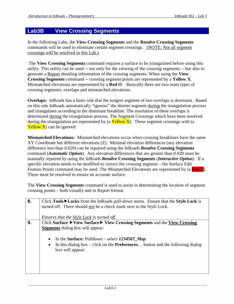
9. Click Surface View Surface View Crossing Segments and the View Crossing Segments dialog box will appear:
• In the Surface: Pulldown – select 1234567_Map • In this dialog box – click on the Preferences… button and the following dialog
box will appear:
Introduction to InRoads - Photogrammetry InRoads SS2 – Lab 3
Lab3-6
• In the dialog box – select the Preference of EXISTING. Then click Load and then click Close and the Preferences dialog box will close.
Leave all other entries as default. The inputs should now correspond to the screen capture depicted in Figure L3-2 (as shown below). Verify to ensure that your input matches the screen capture. Opens the View Crossing Segments dialog box
Figure L3-2 View Crossing Segments
*FYI: Segment Crossing Points and Mismatched elevations are both placed in MicroStation on the named level ‘ECON_E_Crossing-Breakline-Cell’. Segment Crossing Points are viewed with a yellow X and are controlled through ‘ByLevel’. Since ByLevel can only control one symbol at a time, the Mismatched elevations are not set up as ByLevel. Mismatched elevations will view as a red O and are manually set in the InRoads Text Symbology dialog which can be accessed by double clicking the Mismatched Elevation text under the Object heading. This information is provided to explain why one object says BYLEVEL and the other object has a red square in the View Crossing Segments dialog.
Introduction to InRoads - Photogrammetry InRoads SS2 – Lab 3
Lab3-7
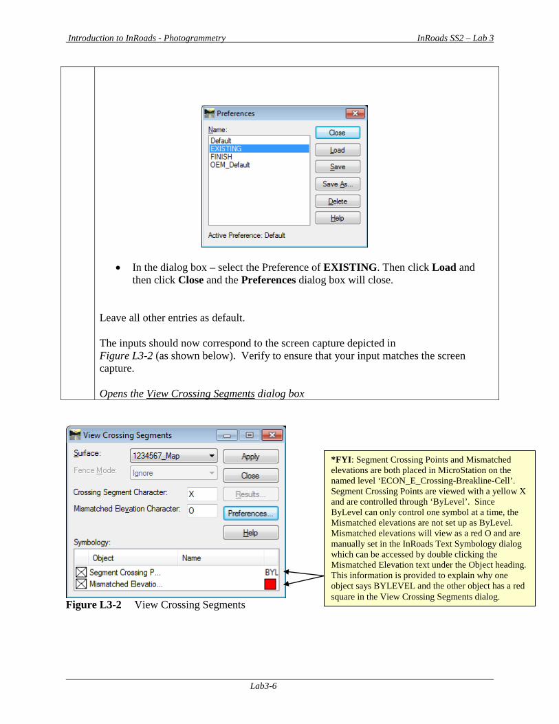
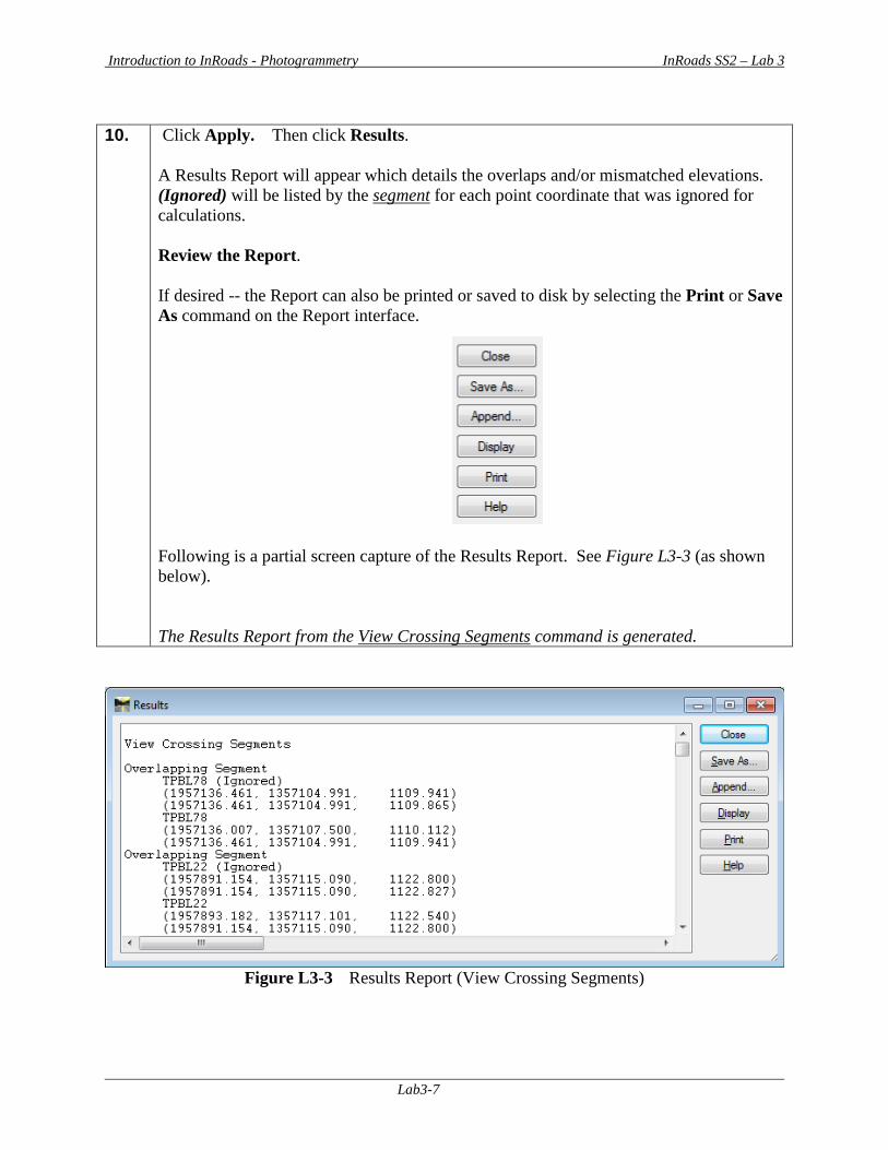
10. Click Apply. Then click Results.
A Results Report will appear which details the overlaps and/or mismatched elevations. (Ignored) will be listed by the segment for each point coordinate that was ignored for calculations. Review the Report. If desired -- the Report can also be printed or saved to disk by selecting the Print or Save As command on the Report interface. Following is a partial screen capture of the Results Report. See Figure L3-3 (as shown below). The Results Report from the View Crossing Segments command is generated.
Figure L3-3 Results Report (View Crossing Segments)
Introduction to InRoads - Photogrammetry InRoads SS2 – Lab 3
Lab3-8
11. In the “Results Report” – click Close. The View Crossing Segments dialog box should still be active. The View Crossing Segments Results Report is closed.
12. Click Close to close out of the View Crossing Segments dialog box. The next Lab will detail how to resolve the mismatched elevations. Closes the View Crossing Segments dialog box.
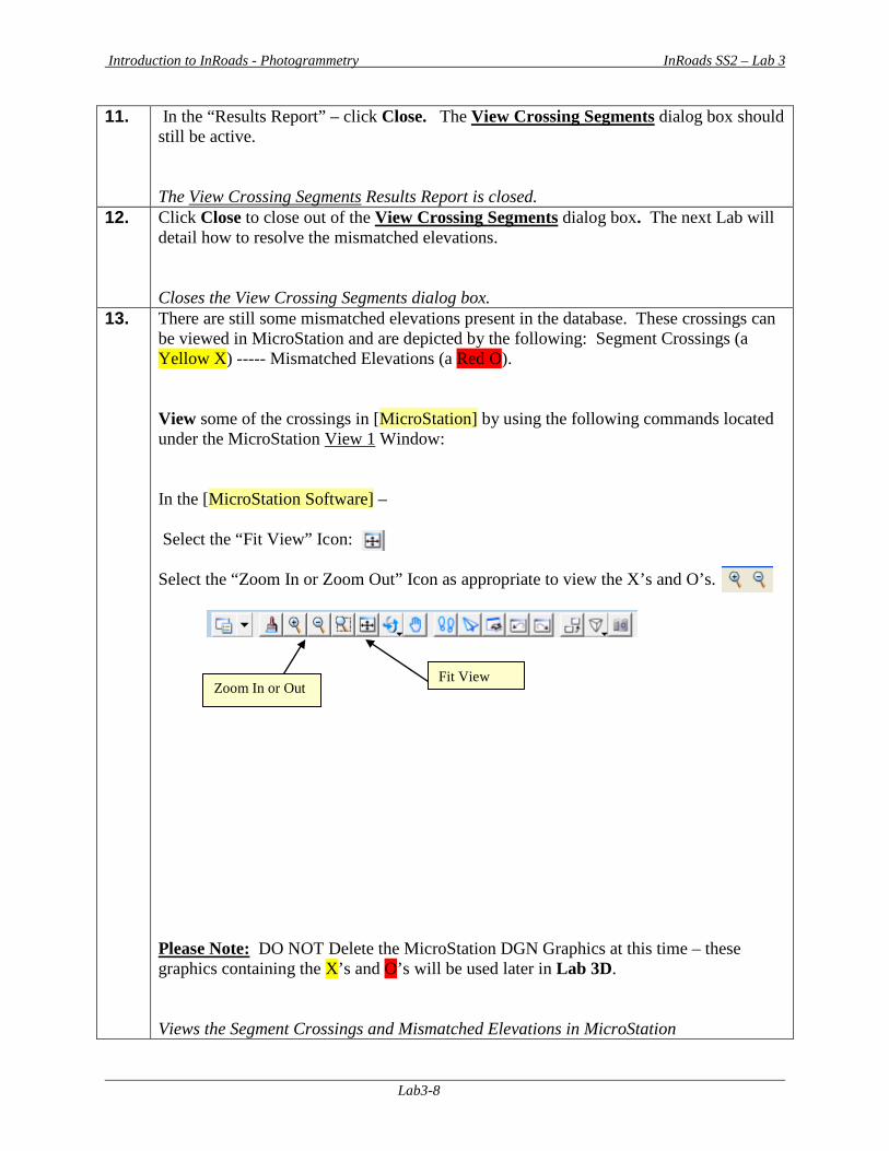
13. There are still some mismatched elevations present in the database. These crossings can be viewed in MicroStation and are depicted by the following: Segment Crossings (a Yellow X) ----- Mismatched Elevations (a Red O). View some of the crossings in [MicroStation] by using the following commands located under the MicroStation View 1 Window: In the [MicroStation Software] – Select the “Fit View” Icon: Select the “Zoom In or Zoom Out” Icon as appropriate to view the X’s and O’s.
Please Note: DO NOT Delete the MicroStation DGN Graphics at this time – these graphics containing the X’s and O’s will be used later in Lab 3D. Views the Segment Crossings and Mismatched Elevations in MicroStation
Fit View Zoom In or Out
Introduction to InRoads - Photogrammetry InRoads SS2 – Lab 3
Lab3-9
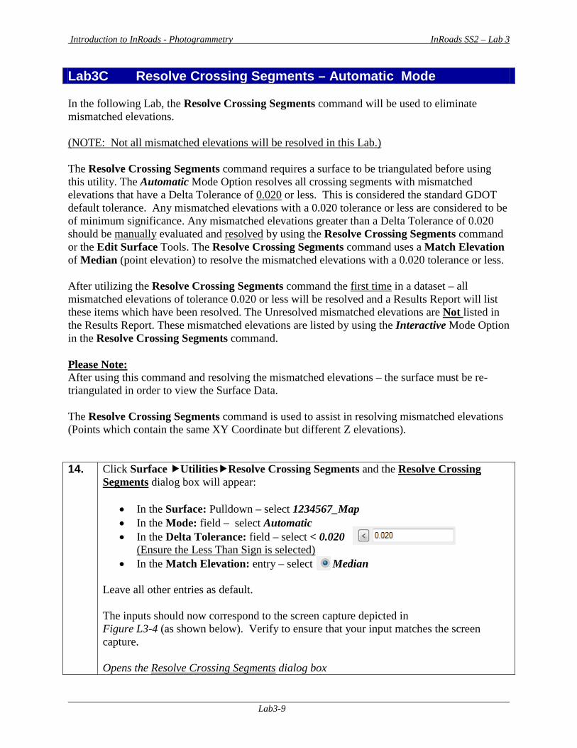
Lab3C Resolve Crossing Segments – Automatic Mode In the following Lab, the Resolve Crossing Segments command will be used to eliminate mismatched elevations. (NOTE: Not all mismatched elevations will be resolved in this Lab.) The Resolve Crossing Segments command requires a surface to be triangulated before using this utility. The Automatic Mode Option resolves all crossing segments with mismatched elevations that have a Delta Tolerance of 0.020 or less. This is considered the standard GDOT default tolerance. Any mismatched elevations with a 0.020 tolerance or less are considered to be of minimum significance. Any mismatched elevations greater than a Delta Tolerance of 0.020 should be manually evaluated and resolved by using the Resolve Crossing Segments command or the Edit Surface Tools. The Resolve Crossing Segments command uses a Match Elevation of Median (point elevation) to resolve the mismatched elevations with a 0.020 tolerance or less. After utilizing the Resolve Crossing Segments command the first time in a dataset – all mismatched elevations of tolerance 0.020 or less will be resolved and a Results Report will list these items which have been resolved. The Unresolved mismatched elevations are Not listed in the Results Report. These mismatched elevations are listed by using the Interactive Mode Option in the Resolve Crossing Segments command. Please Note: After using this command and resolving the mismatched elevations – the surface must be re-triangulated in order to view the Surface Data. The Resolve Crossing Segments command is used to assist in resolving mismatched elevations (Points which contain the same XY Coordinate but different Z elevations). 14. Click Surface UtilitiesResolve Crossing Segments and the Resolve Crossing
Segments dialog box will appear:
• In the Surface: Pulldown – select 1234567_Map • In the Mode: field – select Automatic • In the Delta Tolerance: field – select < 0.020
(Ensure the Less Than Sign is selected) • In the Match Elevation: entry – select Median
Leave all other entries as default. The inputs should now correspond to the screen capture depicted in Figure L3-4 (as shown below). Verify to ensure that your input matches the screen capture. Opens the Resolve Crossing Segments dialog box
Introduction to InRoads - Photogrammetry InRoads SS2 – Lab 3
Lab3-10
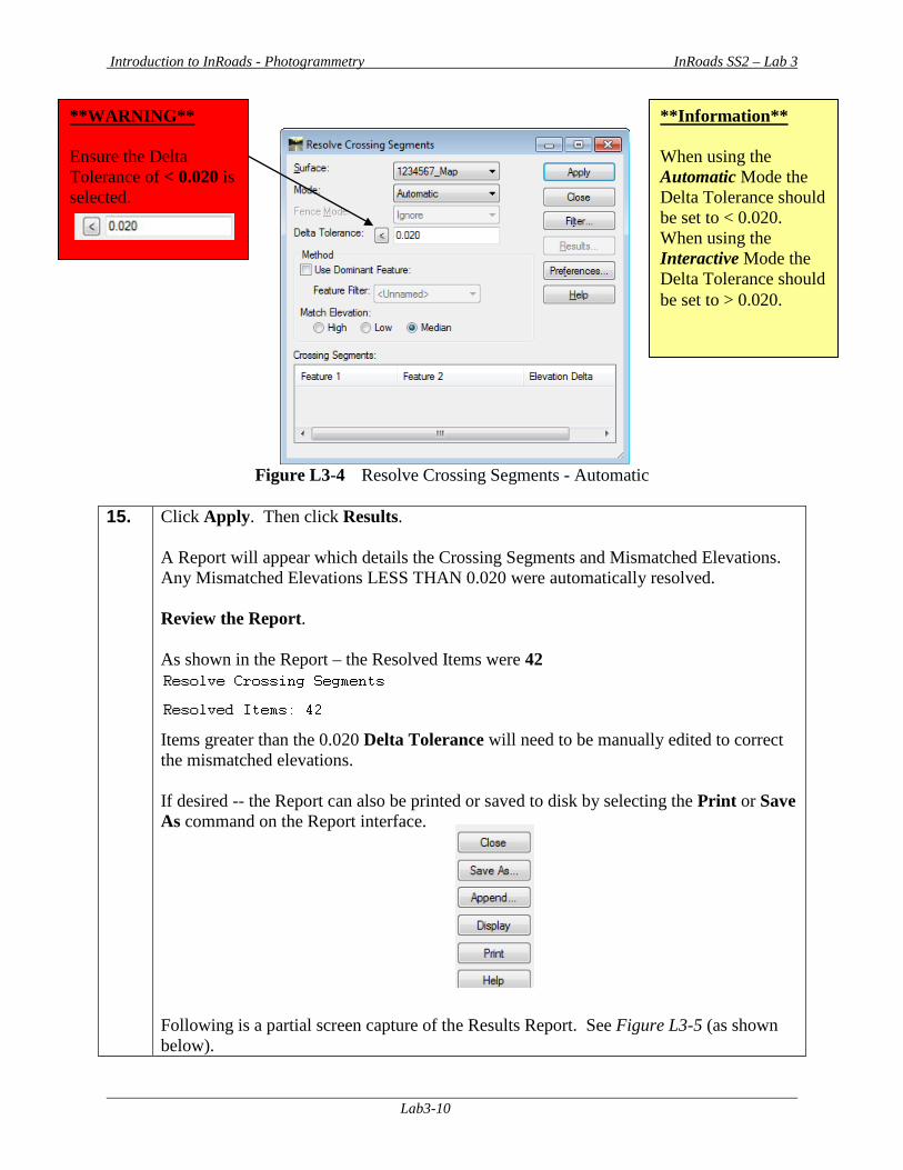
Figure L3-4 Resolve Crossing Segments - Automatic
15. Click Apply. Then click Results.
A Report will appear which details the Crossing Segments and Mismatched Elevations. Any Mismatched Elevations LESS THAN 0.020 were automatically resolved. Review the Report. As shown in the Report – the Resolved Items were 42
Items greater than the 0.020 Delta Tolerance will need to be manually edited to correct the mismatched elevations. If desired -- the Report can also be printed or saved to disk by selecting the Print or Save As command on the Report interface. Following is a partial screen capture of the Results Report. See Figure L3-5 (as shown below).
**WARNING** Ensure the Delta Tolerance of < 0.020 is selected.
**Information** When using the Automatic Mode the Delta Tolerance should be set to < 0.020. When using the Interactive Mode the Delta Tolerance should be set to > 0.020.
Introduction to InRoads - Photogrammetry InRoads SS2 – Lab 3
Lab3-11
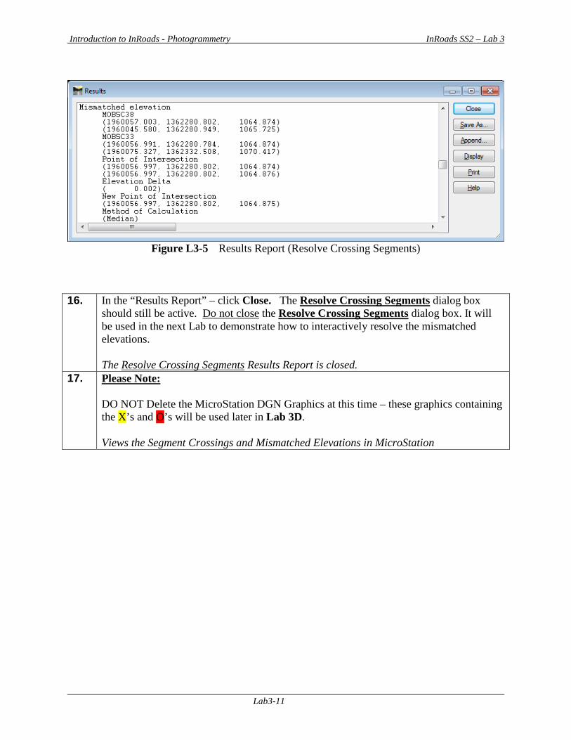
Figure L3-5 Results Report (Resolve Crossing Segments)
16. In the “Results Report” – click Close. The Resolve Crossing Segments dialog box
should still be active. Do not close the Resolve Crossing Segments dialog box. It will be used in the next Lab to demonstrate how to interactively resolve the mismatched elevations. The Resolve Crossing Segments Results Report is closed.
17. Please Note: DO NOT Delete the MicroStation DGN Graphics at this time – these graphics containing the X’s and O’s will be used later in Lab 3D. Views the Segment Crossings and Mismatched Elevations in MicroStation
Introduction to InRoads - Photogrammetry InRoads SS2 – Lab 3
Lab3-12
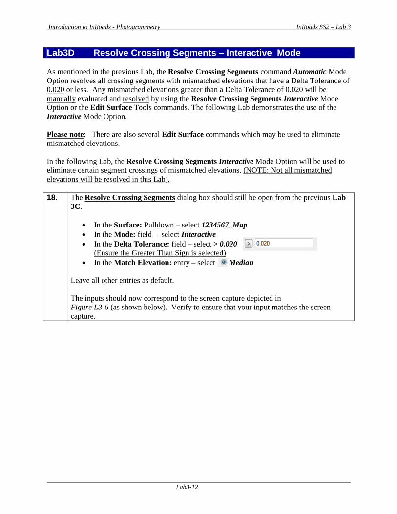
Lab3D Resolve Crossing Segments – Interactive Mode As mentioned in the previous Lab, the Resolve Crossing Segments command Automatic Mode Option resolves all crossing segments with mismatched elevations that have a Delta Tolerance of 0.020 or less. Any mismatched elevations greater than a Delta Tolerance of 0.020 will be manually evaluated and resolved by using the Resolve Crossing Segments Interactive Mode Option or the Edit Surface Tools commands. The following Lab demonstrates the use of the Interactive Mode Option. Please note: There are also several Edit Surface commands which may be used to eliminate mismatched elevations. In the following Lab, the Resolve Crossing Segments Interactive Mode Option will be used to eliminate certain segment crossings of mismatched elevations. (NOTE: Not all mismatched elevations will be resolved in this Lab). 18. The Resolve Crossing Segments dialog box should still be open from the previous Lab
3C.
• In the Surface: Pulldown – select 1234567_Map • In the Mode: field – select Interactive • In the Delta Tolerance: field – select > 0.020
(Ensure the Greater Than Sign is selected) • In the Match Elevation: entry – select Median
Leave all other entries as default. The inputs should now correspond to the screen capture depicted in Figure L3-6 (as shown below). Verify to ensure that your input matches the screen capture.
Introduction to InRoads - Photogrammetry InRoads SS2 – Lab 3
Lab3-13
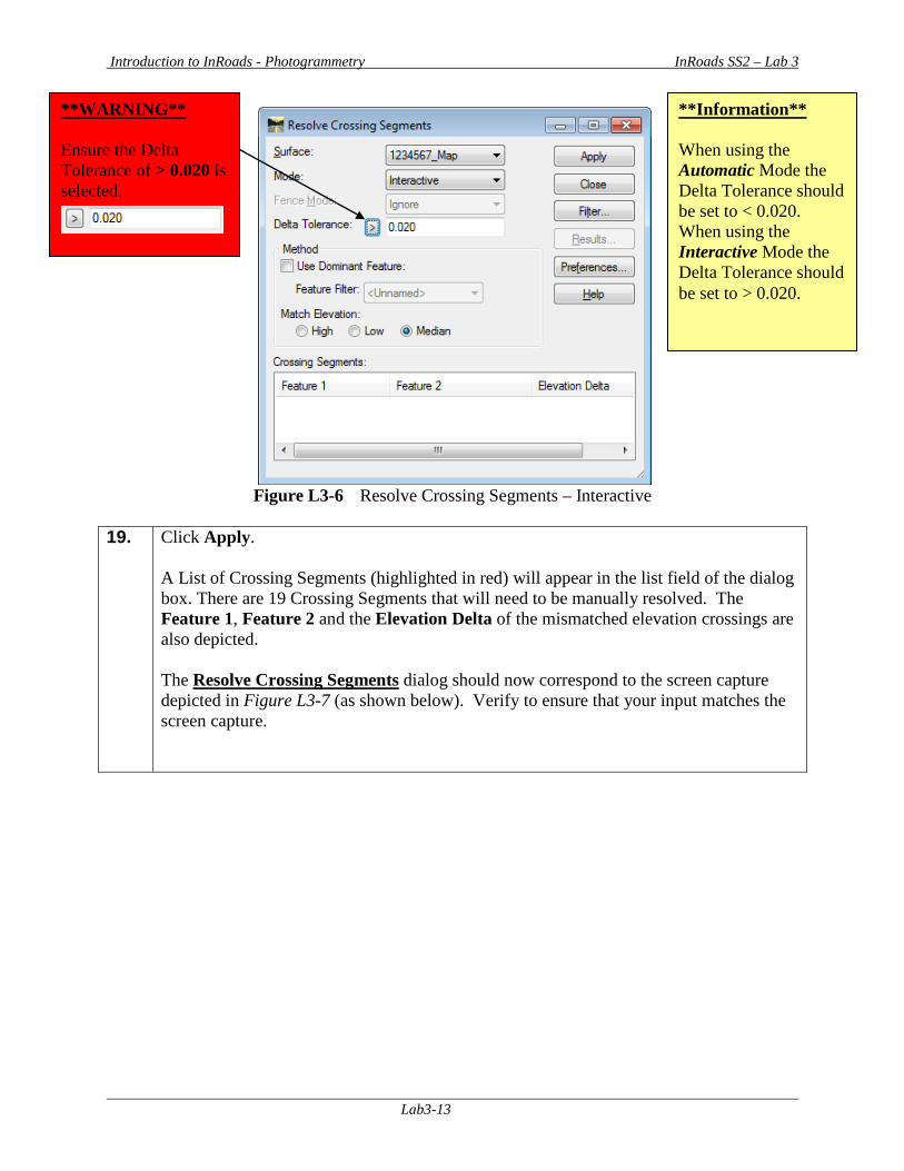
Figure L3-6 Resolve Crossing Segments – Interactive
19. Click Apply.
A List of Crossing Segments (highlighted in red) will appear in the list field of the dialog box. There are 19 Crossing Segments that will need to be manually resolved. The Feature 1, Feature 2 and the Elevation Delta of the mismatched elevation crossings are also depicted. The Resolve Crossing Segments dialog should now correspond to the screen capture depicted in Figure L3-7 (as shown below). Verify to ensure that your input matches the screen capture.
**WARNING** Ensure the Delta Tolerance of > 0.020 is selected.
**Information** When using the Automatic Mode the Delta Tolerance should be set to < 0.020. When using the Interactive Mode the Delta Tolerance should be set to > 0.020.
Introduction to InRoads - Photogrammetry InRoads SS2 – Lab 3
Lab3-14
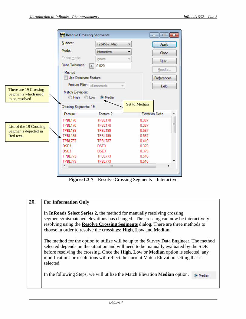
Figure L3-7 Resolve Crossing Segments – Interactive
20. For Information Only In InRoads Select Series 2, the method for manually resolving crossing segments/mismatched elevations has changed. The crossing can now be interactively resolving using the Resolve Crossing Segments dialog. There are three methods to choose in order to resolve the crossings: High, Low and Median. The method for the option to utilize will be up to the Survey Data Engineer. The method selected depends on the situation and will need to be manually evaluated by the SDE before resolving the crossing. Once the High, Low or Median option is selected, any modifications or resolutions will reflect the current Match Elevation setting that is selected. In the following Steps, we will utilize the Match Elevation Median option.
There are 19 Crossing Segments which need to be resolved.
Set to Median
List of the 19 Crossing Segments depicted in Red text.
Introduction to InRoads - Photogrammetry InRoads SS2 – Lab 3
Lab3-15
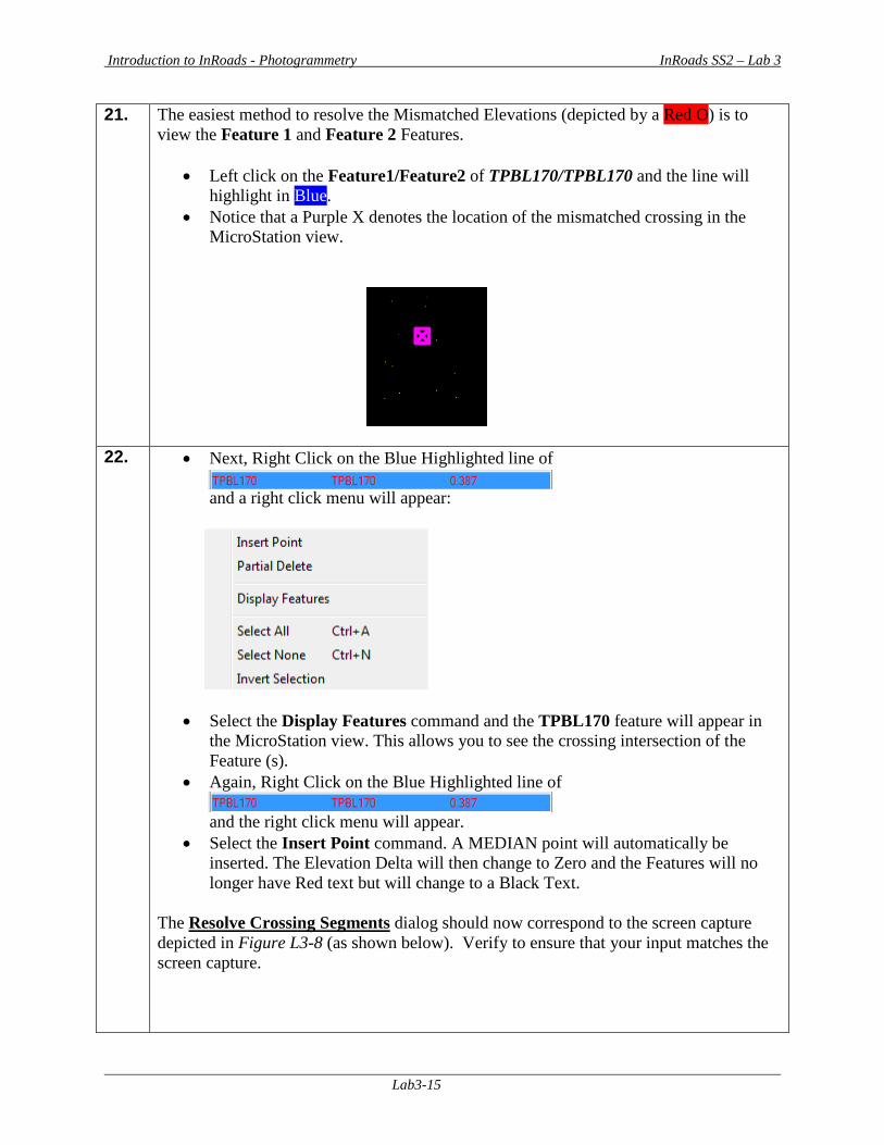
21. The easiest method to resolve the Mismatched Elevations (depicted by a Red O) is to view the Feature 1 and Feature 2 Features.
• Left click on the Feature1/Feature2 of TPBL170/TPBL170 and the line will highlight in Blue.
• Notice that a Purple X denotes the location of the mismatched crossing in the MicroStation view.
22. • Next, Right Click on the Blue Highlighted line of and a right click menu will appear:
• Select the Display Features command and the TPBL170 feature will appear in the MicroStation view. This allows you to see the crossing intersection of the Feature (s).
• Again, Right Click on the Blue Highlighted line of and the right click menu will appear.
• Select the Insert Point command. A MEDIAN point will automatically be inserted. The Elevation Delta will then change to Zero and the Features will no longer have Red text but will change to a Black Text.
The Resolve Crossing Segments dialog should now correspond to the screen capture depicted in Figure L3-8 (as shown below). Verify to ensure that your input matches the screen capture.
Introduction to InRoads - Photogrammetry InRoads SS2 – Lab 3
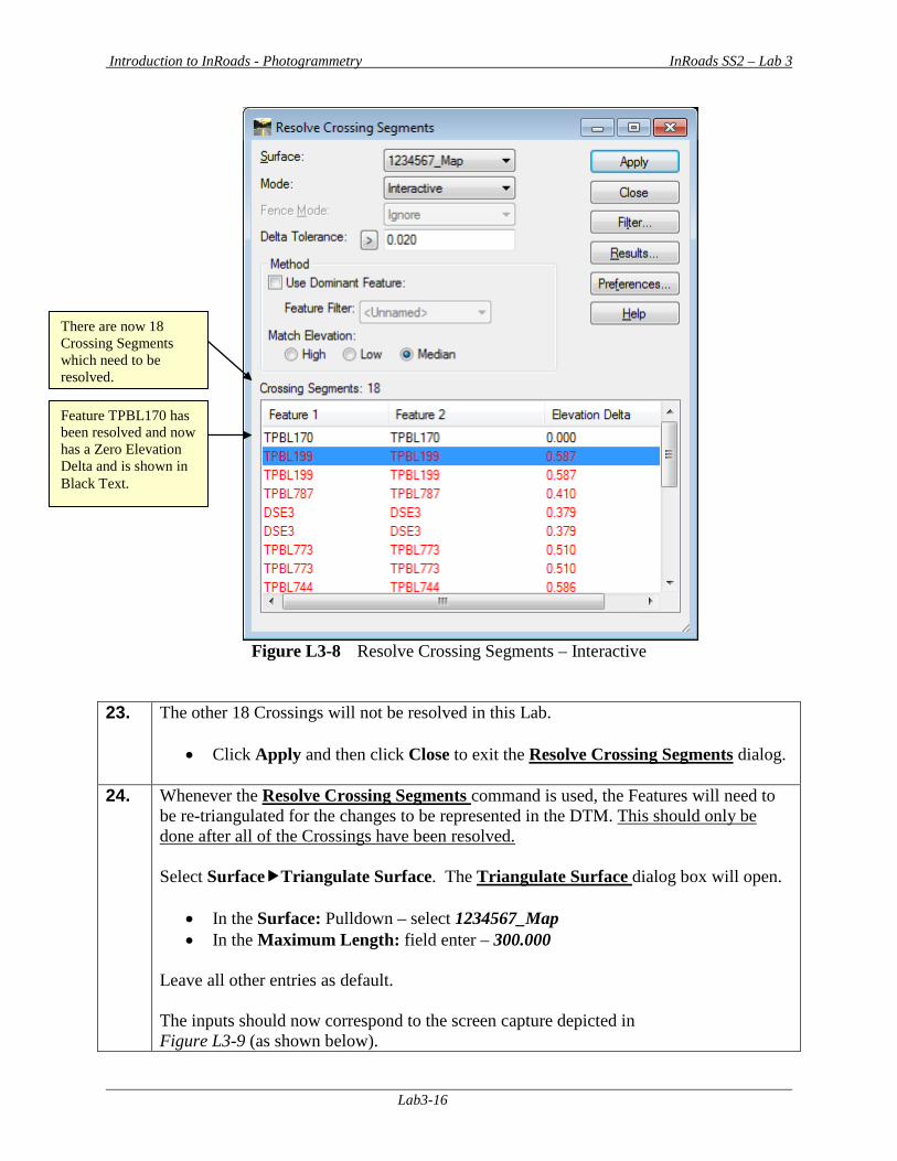
Lab3-16
Figure L3-8 Resolve Crossing Segments – Interactive
23. The other 18 Crossings will not be resolved in this Lab.
• Click Apply and then click Close to exit the Resolve Crossing Segments dialog.
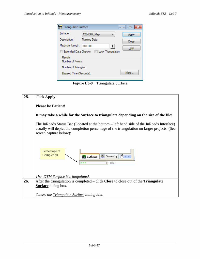
24. Whenever the Resolve Crossing Segments command is used, the Features will need to be re-triangulated for the changes to be represented in the DTM. This should only be done after all of the Crossings have been resolved. Select SurfaceTriangulate Surface. The Triangulate Surface dialog box will open.
• In the Surface: Pulldown – select 1234567_Map • In the Maximum Length: field enter – 300.000
Leave all other entries as default. The inputs should now correspond to the screen capture depicted in Figure L3-9 (as shown below).
There are now 18 Crossing Segments which need to be resolved.
Feature TPBL170 has been resolved and now has a Zero Elevation Delta and is shown in Black Text.
Introduction to InRoads - Photogrammetry InRoads SS2 – Lab 3
Lab3-17
Figure L3-9 Triangulate Surface
25. Click Apply.
Please be Patient! It may take a while for the Surface to triangulate depending on the size of the file! The InRoads Status Bar (Located at the bottom – left hand side of the InRoads Interface) usually will depict the completion percentage of the triangulation on larger projects. (See screen capture below):
The DTM Surface is triangulated.
26. After the triangulation is completed – click Close to close out of the Triangulate Surface dialog box. Closes the Triangulate Surface dialog box.
Percentage of Completion
Introduction to InRoads - Photogrammetry InRoads SS2 – Lab 3
Lab3-18
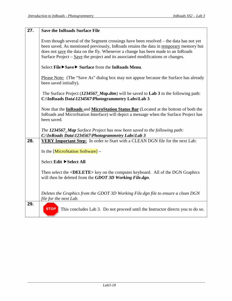
27. Save the InRoads Surface File Even though several of the Segment crossings have been resolved – the data has not yet been saved. As mentioned previously, InRoads retains the data in temporary memory but does not save the data on the fly. Whenever a change has been made to an InRoads Surface Project – Save the project and its associated modifications or changes. Select FileSave Surface from the InRoads Menu. Please Note: (The “Save As” dialog box may not appear because the Surface has already been saved initially). The Surface Project (1234567_Map.dtm) will be saved to Lab 3 in the following path: C:\InRoads Data\1234567\Photogrammetry Labs\Lab 3 Note that the InRoads and MicroStation Status Bar (Located at the bottom of both the InRoads and MicroStation Interface) will depict a message when the Surface Project has been saved. The 1234567_Map Surface Project has now been saved to the following path: C:\InRoads Data\1234567\Photogrammetry Labs\Lab 3
28. VERY Important Step: In order to Start with a CLEAN DGN file for the next Lab: In the [MicroStation Software] – Select Edit Select All Then select the <DELETE> key on the computer keyboard. All of the DGN Graphics will then be deleted from the GDOT 3D Working File.dgn. Deletes the Graphics from the GDOT 3D Working File.dgn file to ensure a clean DGN file for the next Lab.
29. This concludes Lab 3. Do not proceed until the Instructor directs you to do so.
Introduction to InRoads - Photogrammetry InRoads SS2 – Lab 4
Lab4-1
Lab 4 Create an Exterior Mapping Boundary
Objective After the Segment Crossings have been resolved – an Exterior Boundary (a Limit Line with Feature Style of (TOPO_E_TLIML) will be created to represent the bounds of the mapping data. This Exterior Boundary is also used in the trimming of extraneous triangles from the Mapping DTM Surface. During the creation of a DTM Surface, extraneous triangles (erroneous triangle data) will be generated which does not represent actual Surface data. A common situation where this occurs is at “T Intersections”. In order to remove these triangles (which represent inaccurate data) an Exterior Boundary is required. Although there are several methods to create an Exterior Mapping Boundary – the method depicted in the following Lab represents a common practice which will work for most situations. Due to the current InRoads Software functionality, InRoads requires that the Exterior Boundary be composed of existing surface data located just inside of the outer-most Feature Points represented in the DTM Project. In order to create the Exterior Boundary (and the exterior Boundary points) – a MicroStation SmartLine command can be used to digitize new points or connect existing points in MicroStation. This Boundary MUST be a complex shape (one continuous entity) so that the DTM triangulation will honor the limits of the Exterior Boundary. *Please Note the following InRoads Requirements:
• InRoads has a requirement that only ONE Exterior Boundary may be present in a DTM Project.
• The Exterior Boundary must be one continuous complex shape. • The Existing Feature Points (or new digitized points) on the exterior Boundary must be
located on the Existing Surface in order for the Boundary to trim triangles correctly. The Exterior Boundary will be draped on the Existing DTM Surface (in order to obtain point elevations) – so always ensure that the Boundary is located on actual surface data.
• If there are Obscured Areas on the outside of the Surface data – the Exterior Boundary must not include these areas inside of the Exterior Boundary.
• Interior Obscured Areas can be included inside the Exterior Boundary.
The objective of Lab 4 is to:
• Create an Exterior Mapping Boundary in MicroStation
Introduction to InRoads - Photogrammetry InRoads SS2 – Lab 4
Lab4-2
Lab4 Create an Exterior Mapping Boundary In this Lab you will be creating an Exterior Boundary which will represent the extents of the Mapping Data. This Exterior Boundary will be used in a later Lab to trim extraneous triangles from the Existing Surface Model. The majority of the Lab work for the generation of the Exterior Boundary will be performed in the [MicroStation Software]. The user will need to become familiar with MicroStation commands in order to successfully perform the steps to generate the Exterior Boundary. 1. Starting Clean
In order to ensure that you are working with a “clean” database – you will close MicroStation and InRoads if they are still running from a previous Lab: To CLOSE MicroStation and InRoads - Select FileExit from the [MicroStation Menu]. If any messages appear regarding the saving of projects – Select This closes BOTH the MicroStation and InRoads Software(s).
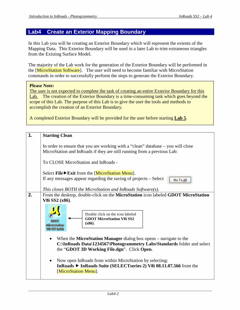
2. From the desktop, double-click on the MicroStation icon labeled GDOT MicroStation V8i SS2 (x86).
• When the MicroStation Manager dialog box opens – navigate to the C:\InRoads Data\1234567\Photogrammetry Labs\Standards folder and select the “GDOT 3D Working File.dgn”. Click Open.
• Now open InRoads from within MicroStation by selecting:
InRoads InRoads Suite (SELECTseries 2) V8i 08.11.07.566 from the [MicroStation Menu].
Please Note: The user is not expected to complete the task of creating an entire Exterior Boundary for this Lab. The creation of the Exterior Boundary is a time-consuming task which goes beyond the scope of this Lab. The purpose of this Lab is to give the user the tools and methods to accomplish the creation of an Exterior Boundary. A completed Exterior Boundary will be provided for the user before starting Lab 5.
Double click on the icon labeled GDOT MicroStation V8i SS2 (x86).
Introduction to InRoads - Photogrammetry InRoads SS2 – Lab 4
Lab4-3
3. Load the InRoads Surface File Select FileOpen from the InRoads Menu. The Project Defaults (which were set up in Lab 1C) are set to the following Path: C:\InRoads Data\1234567\Photogrammetry Labs. Browse to the following path: C:\InRoads Data\1234567\Photogrammetry Labs\Lab4 Select the file named: 1234567_Map.dtm Click Open and then click Cancel. The 1234567_Map.dtm Surface file will open.
4. Click ToolsLocks from the InRoads pull-down menu. Ensure that the following Locks are turned OFF. There should not be a check mark next to the following: Feature Filter Feature Highlight Style Delete Ink Element Snap Station This is an important step. Ensures that the appropriate Locks are turned OFF.
5. Click ToolsLocks from the InRoads pull-down menu. Ensure that the following Locks are set as indicated below: Pencil Lock is set to Pencil Locate Lock is set to Features Point Snap Lock is checked Report Lock is checked Toolbar Lock is checked This is an important step. Ensures that the appropriate Locks are turned ON.
Introduction to InRoads - Photogrammetry InRoads SS2 – Lab 4
Lab4-4
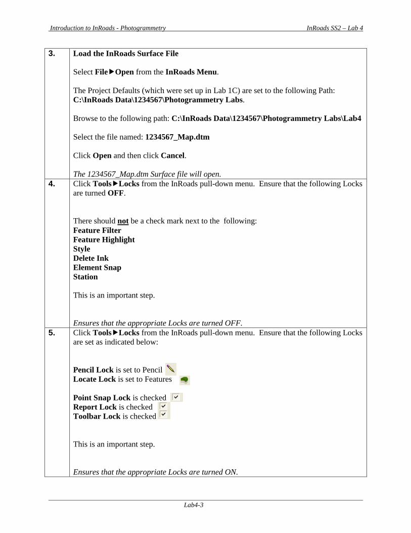
6. Click SurfaceView SurfaceFeatures from the InRoads pull-down menu and the View Features dialog box will appear.
• In the Surface: Pulldown – select 1234567_Map When the dialog is first opened – all of the Features in the Features: list will be highlighted in blue (Leave all of the features “highlighted blue). This will ensure that all Features are graphically viewed.
Leave all other entries as default. The inputs should now correspond to the screen capture depicted in Figure L4-1 (as shown below). Verify to ensure that your input matches the screen capture. Opens the View Features dialog box
Figure L4-1 View Features
7. Click Apply.
Please Be Patient! It may take a while for the Features to View depending on the size of the file! Views the 1234567_Map Features in MicroStation
Introduction to InRoads - Photogrammetry InRoads SS2 – Lab 4
Lab4-5
8. Click Close to close out of the View Features dialog box. Closes the View Features dialog box.
9. In order to create the Exterior Boundary – the user must become familiar with the appropriate settings and commands to utilize in MicroStation. A good resource for this information is the “MicroStation Help Files” which is located in the [MicroStation Menu] under HelpContents. Please refer to this resource for additional information. Refers to the location for the MicroStation “Help Files”.
10. For Information Only The following MicroStation options will assist the user in creating the Exterior Boundary. These may be turned on/off based on the situation and the user’s preference. Note: The user will be provided the steps to turn these options on/off later in this Lab.
A. AccuDraw should be turned off. (When turned on – the point is harder to select.) B. AccuSnap should be turned off (unless selecting a point). C. When selecting a point (if AccuSnap is turned on) - a “yellow will appear to
denote the point location. D. The Default Snap must be set to “Keypoint”. E. When selecting the point – do not use the tentative snap button to pick the point --
- select the point by LEFT clicking on the point! Initiates the appropriate MicroStation settings.
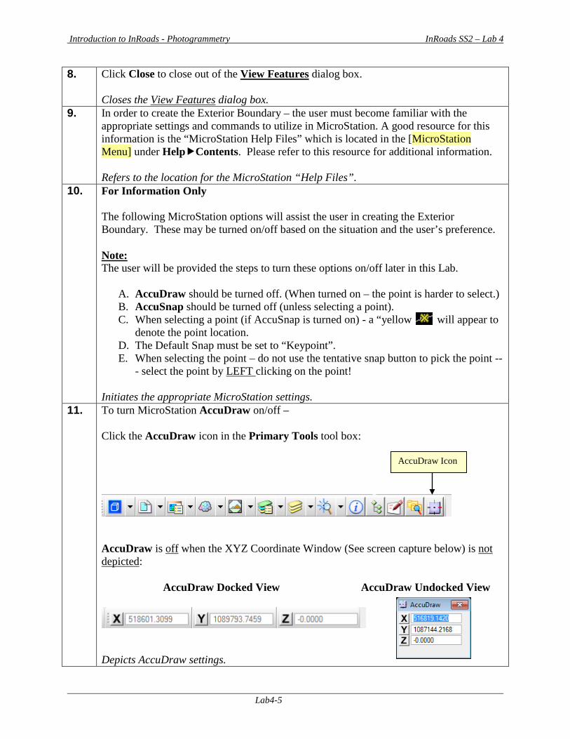
11. To turn MicroStation AccuDraw on/off – Click the AccuDraw icon in the Primary Tools tool box:
AccuDraw is off when the XYZ Coordinate Window (See screen capture below) is not depicted: AccuDraw Docked View AccuDraw Undocked View
Depicts AccuDraw settings.
AccuDraw Icon
Introduction to InRoads - Photogrammetry InRoads SS2 – Lab 4
Lab4-6
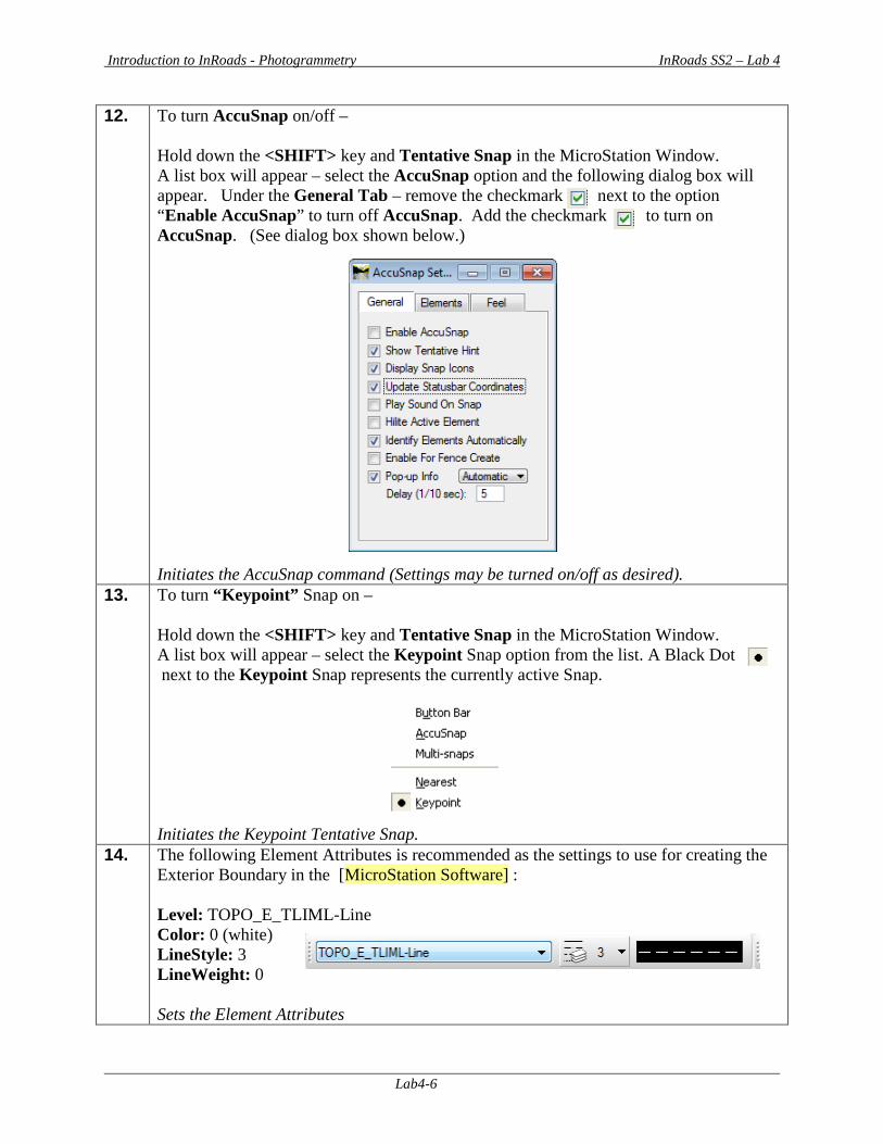
12. To turn AccuSnap on/off – Hold down the <SHIFT> key and Tentative Snap in the MicroStation Window. A list box will appear – select the AccuSnap option and the following dialog box will appear. Under the General Tab – remove the checkmark next to the option “Enable AccuSnap” to turn off AccuSnap. Add the checkmark to turn on AccuSnap. (See dialog box shown below.) Initiates the AccuSnap command (Settings may be turned on/off as desired).
13. To turn “Keypoint” Snap on – Hold down the <SHIFT> key and Tentative Snap in the MicroStation Window. A list box will appear – select the Keypoint Snap option from the list. A Black Dot next to the Keypoint Snap represents the currently active Snap. Initiates the Keypoint Tentative Snap.
14. The following Element Attributes is recommended as the settings to use for creating the Exterior Boundary in the [MicroStation Software] : Level: TOPO_E_TLIML-Line Color: 0 (white) LineStyle: 3 LineWeight: 0 Sets the Element Attributes
Introduction to InRoads - Photogrammetry InRoads SS2 – Lab 4
Lab4-7
15. For Information Only Since this is a “Working DGN File” and the Exterior Boundary is a temporary graphic – it does not matter what color, level, linestyle, etc. you select to create the Exterior Boundary. After importation of the boundary into InRoads – the temporary graphics will be deleted. The actual Exterior Boundary (after it is imported into InRoads) will automatically depict the correct Feature Style attributes - color, weight, level, etc. Sets the Element Attributes to use for the Exterior Boundary.
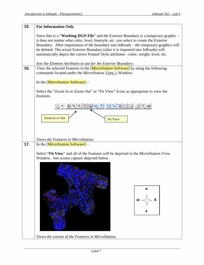
16. View the selected Features in the [MicroStation Software] by using the following commands located under the MicroStation View 1 Window: In the [MicroStation Software] – Select the “Zoom In or Zoom Out” or “Fit View” Icons as appropriate to view the Features.
Views the Features in MicroStation.
17. In the [MicroStation Software] – Select “Fit View” and all of the Features will be depicted in the MicroStation View Window. See screen capture depicted below. Views the extents of the Features in MicroStation.
Fit View Zoom In or Out
Introduction to InRoads - Photogrammetry InRoads SS2 – Lab 4
Lab4-8
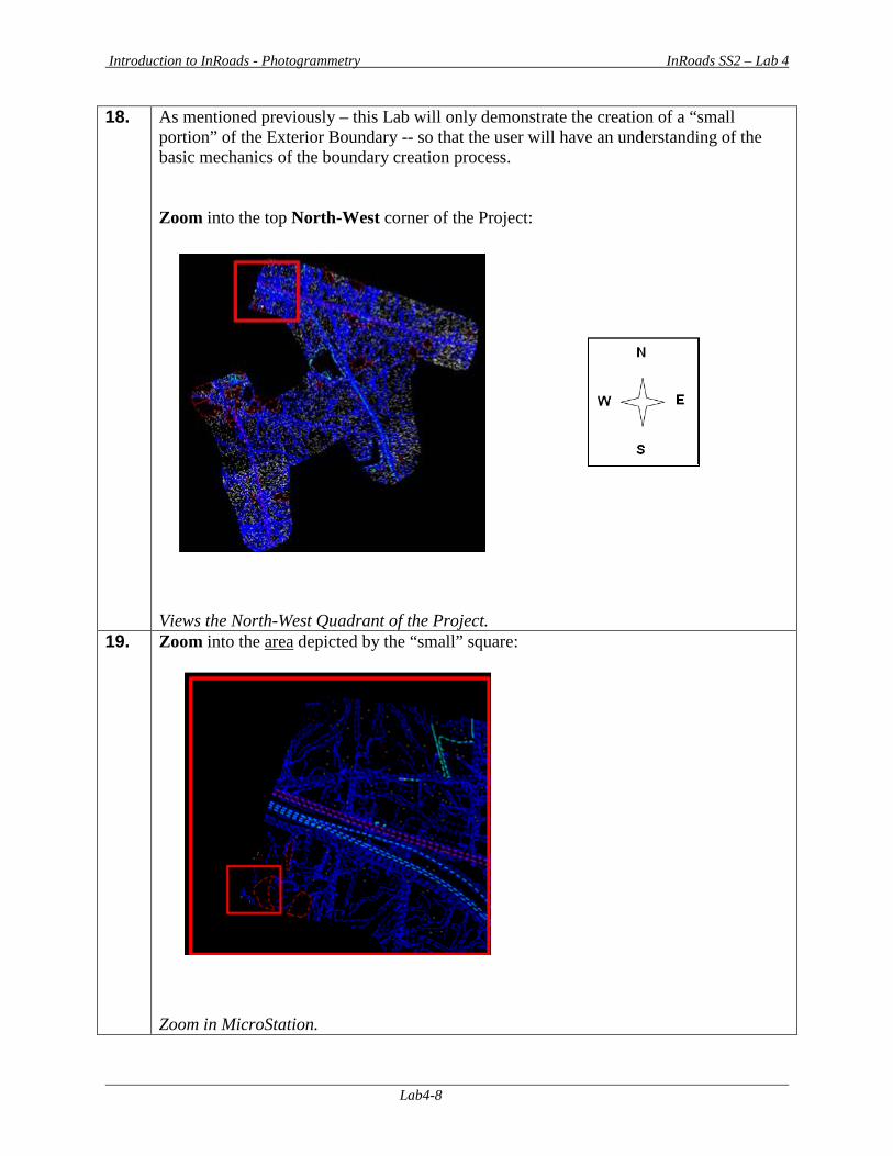
18. As mentioned previously – this Lab will only demonstrate the creation of a “small portion” of the Exterior Boundary -- so that the user will have an understanding of the basic mechanics of the boundary creation process. Zoom into the top North-West corner of the Project: Views the North-West Quadrant of the Project.
19. Zoom into the area depicted by the “small” square: Zoom in MicroStation.
Introduction to InRoads - Photogrammetry InRoads SS2 – Lab 4
Lab4-9
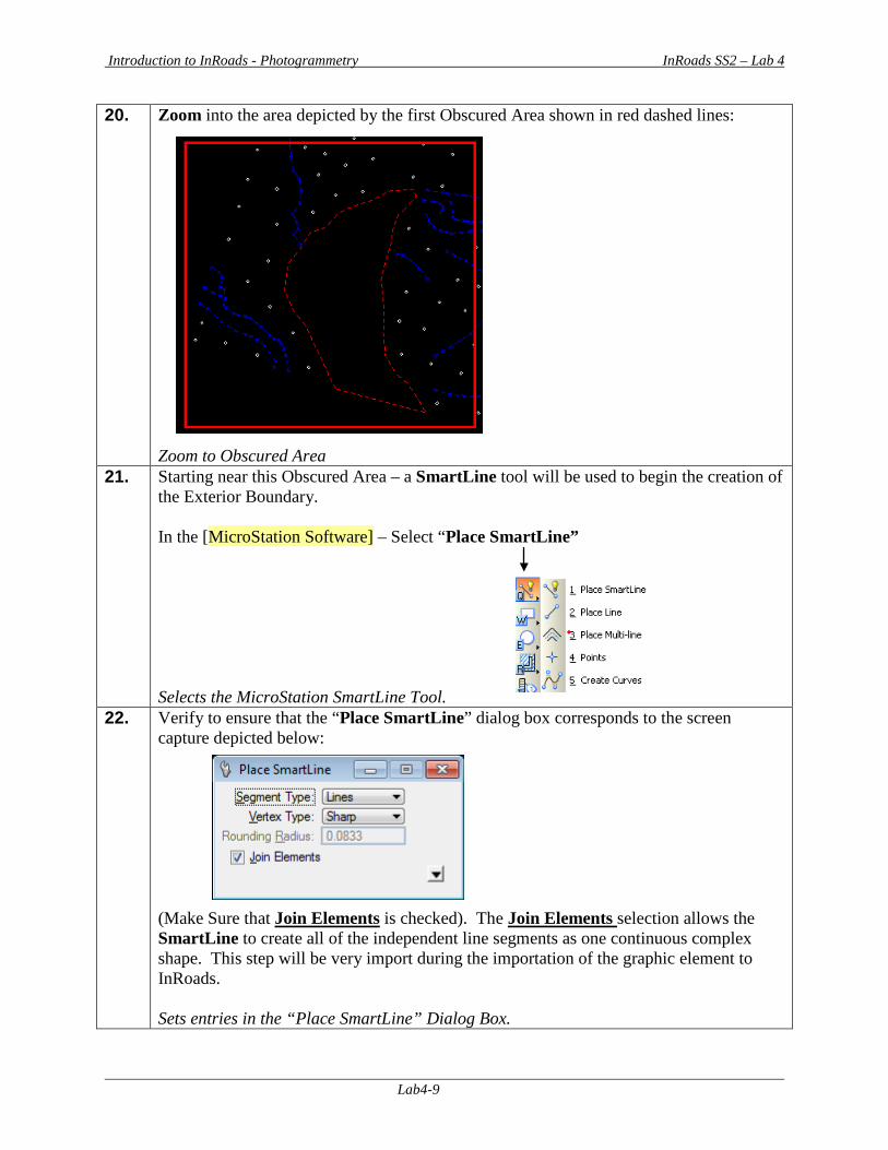
20. Zoom into the area depicted by the first Obscured Area shown in red dashed lines: Zoom to Obscured Area
21. Starting near this Obscured Area – a SmartLine tool will be used to begin the creation of the Exterior Boundary. In the [MicroStation Software] – Select “Place SmartLine” Selects the MicroStation SmartLine Tool.
22. Verify to ensure that the “Place SmartLine” dialog box corresponds to the screen capture depicted below: (Make Sure that Join Elements is checked). The Join Elements selection allows the SmartLine to create all of the independent line segments as one continuous complex shape. This step will be very import during the importation of the graphic element to InRoads. Sets entries in the “Place SmartLine” Dialog Box.
Introduction to InRoads - Photogrammetry InRoads SS2 – Lab 4
Lab4-10
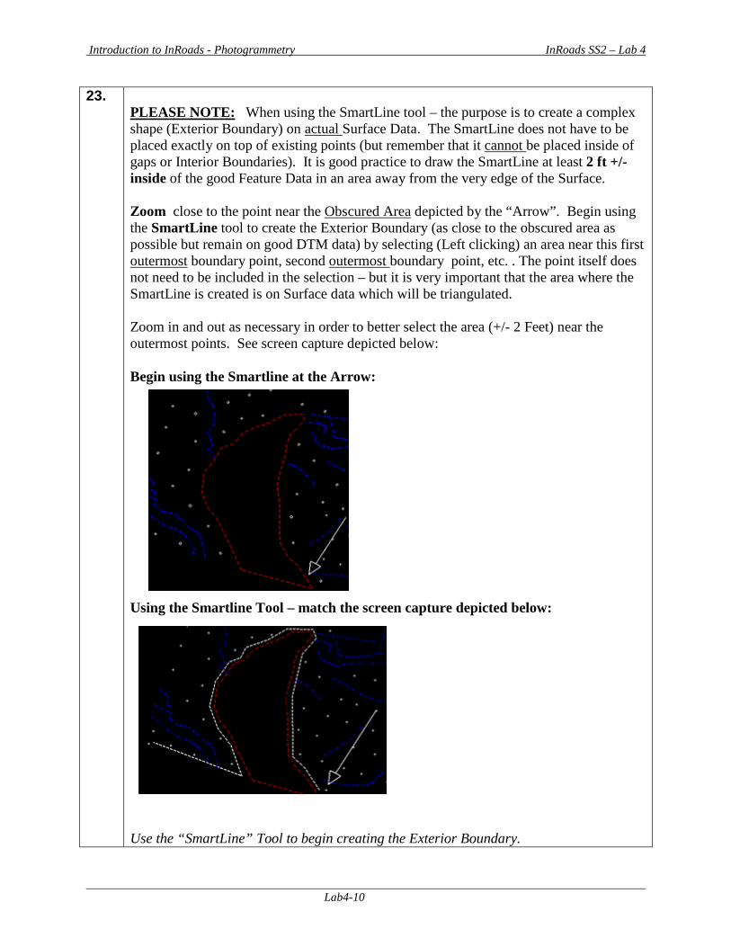
23. PLEASE NOTE: When using the SmartLine tool – the purpose is to create a complex shape (Exterior Boundary) on actual Surface Data. The SmartLine does not have to be placed exactly on top of existing points (but remember that it cannot be placed inside of gaps or Interior Boundaries). It is good practice to draw the SmartLine at least 2 ft +/- inside of the good Feature Data in an area away from the very edge of the Surface. Zoom close to the point near the Obscured Area depicted by the “Arrow”. Begin using the SmartLine tool to create the Exterior Boundary (as close to the obscured area as possible but remain on good DTM data) by selecting (Left clicking) an area near this first outermost boundary point, second outermost boundary point, etc. . The point itself does not need to be included in the selection – but it is very important that the area where the SmartLine is created is on Surface data which will be triangulated. Zoom in and out as necessary in order to better select the area (+/- 2 Feet) near the outermost points. See screen capture depicted below: Begin using the Smartline at the Arrow: Using the Smartline Tool – match the screen capture depicted below: Use the “SmartLine” Tool to begin creating the Exterior Boundary.
Introduction to InRoads - Photogrammetry InRoads SS2 – Lab 4
Lab4-11
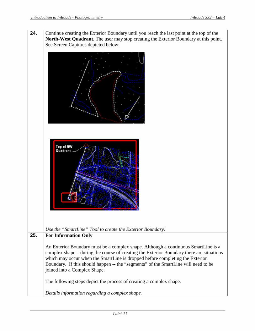
24. Continue creating the Exterior Boundary until you reach the last point at the top of the North-West Quadrant. The user may stop creating the Exterior Boundary at this point. See Screen Captures depicted below: Use the “SmartLine” Tool to create the Exterior Boundary.
25. For Information Only An Exterior Boundary must be a complex shape. Although a continuous SmartLine is a complex shape – during the course of creating the Exterior Boundary there are situations which may occur when the SmartLine is dropped before completing the Exterior Boundary. If this should happen -- the “segments” of the SmartLine will need to be joined into a Complex Shape. The following steps depict the process of creating a complex shape. Details information regarding a complex shape.
Introduction to InRoads - Photogrammetry InRoads SS2 – Lab 4
Lab4-12
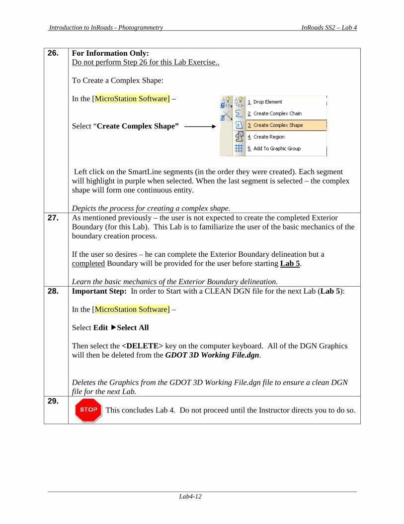
26. For Information Only: Do not perform Step 26 for this Lab Exercise.. To Create a Complex Shape: In the [MicroStation Software] – Select “Create Complex Shape” Left click on the SmartLine segments (in the order they were created). Each segment will highlight in purple when selected. When the last segment is selected – the complex shape will form one continuous entity. Depicts the process for creating a complex shape.
27. As mentioned previously – the user is not expected to create the completed Exterior Boundary (for this Lab). This Lab is to familiarize the user of the basic mechanics of the boundary creation process. If the user so desires – he can complete the Exterior Boundary delineation but a completed Boundary will be provided for the user before starting Lab 5. Learn the basic mechanics of the Exterior Boundary delineation.
28. Important Step: In order to Start with a CLEAN DGN file for the next Lab (Lab 5): In the [MicroStation Software] – Select Edit Select All Then select the <DELETE> key on the computer keyboard. All of the DGN Graphics will then be deleted from the GDOT 3D Working File.dgn. Deletes the Graphics from the GDOT 3D Working File.dgn file to ensure a clean DGN file for the next Lab.
29. This concludes Lab 4. Do not proceed until the Instructor directs you to do so.
Introduction to InRoads - Photogrammetry InRoads SS2 – Lab 5
Lab5-1
Lab 5 Import the Exterior Boundary
Objective After the Exterior Boundary has been created in MicroStation, the graphic complex shape will be imported into the InRoads Existing Surface Model. The Exterior Boundary will be given a Feature Style of TOPO_E_TLIML and will be tagged as Point Type of Exterior. This Exterior Boundary will be used to trim out extraneous (bogus) triangles from the Mapping DTM Surface. The following requirements must be met for the Exterior Boundary to import correctly. InRoads Requirements for Exterior Boundary Importation:
• InRoads has a requirement that only ONE Exterior Boundary may be present in a DTM Project.
• The Exterior Boundary must be one continuous complex shape. • The Existing Feature Points (or new digitized points) on the exterior Boundary must be
located on the Existing Surface in order for the Boundary to trim triangles correctly. The Exterior Boundary will be draped on the Existing DTM Surface (in order to obtain point elevations) – so always ensure that the Boundary is located on actual surface data.
A completed Exterior Boundary will be provided for Lab 5. This Boundary is a Complex Shape which was created in MicroStation by using the SmartLine Command. The objective of Lab 5 is to:
• Create a “Preliminary” triangulated Surface to “Drape” the Exterior Boundary • Merge the Exterior Boundary from a Reference File to the “Working DGN File” • Import the Exterior Boundary into InRoads
Please Note: Lab 5B was created for tutorial purposes only in order to have a “completed” Exterior Boundary already created for the user. In a “Real World” project -- the user would skip (Lab 5B). Only Lab 5A and Lab 5C would be applicable for production projects.

Introduction to InRoads - Photogrammetry InRoads SS2 – Lab 5
Lab5-2
Lab5A Create a “Preliminary” Triangulated Surface In this section of the lab you will be creating a “Preliminary” triangulated surface which will be used later in (Lab 5C) to “drape” the Exterior Boundary on in order to obtain point elevations (Delta Z). 1. Starting Clean
In order to ensure that you are working with a “clean” database – you will close MicroStation and InRoads if they are still running from a previous Lab: To CLOSE MicroStation and InRoads - Select FileExit from the [MicroStation Menu]. If any messages appear regarding the saving of projects – Select This closes BOTH the MicroStation and InRoads Software(s).
2. From the desktop, double-click on the MicroStation icon labeled GDOT MicroStation V8i SS2 (x86).
• When the MicroStation Manager dialog box opens – navigate to the C:\InRoads Data\1234567\Photogrammetry Labs\Standards folder and select the “GDOT 3D Working File.dgn”. Click Open.
• Now open InRoads from within MicroStation by selecting:
InRoads InRoads Suite (SELECTseries 2) V8i 08.11.07.566 from the [MicroStation Menu].
The MicroStation and InRoads Software(s) will open.
3. Load the InRoads Surface File Select FileOpen from the InRoads Menu. The Project Defaults (which were set up in Lab 1C) are set to the following Path: C:\InRoads Data\1234567\Photogrammetry Labs. Browse to the following path: C:\InRoads Data\1234567\Photogrammetry Labs\Lab5 Select the file named: 1234567_Map.dtm Click Open and then click Cancel.
Double click on the icon labeled GDOT MicroStation V8i SS2 (x86).
Introduction to InRoads - Photogrammetry InRoads SS2 – Lab 5
Lab5-3
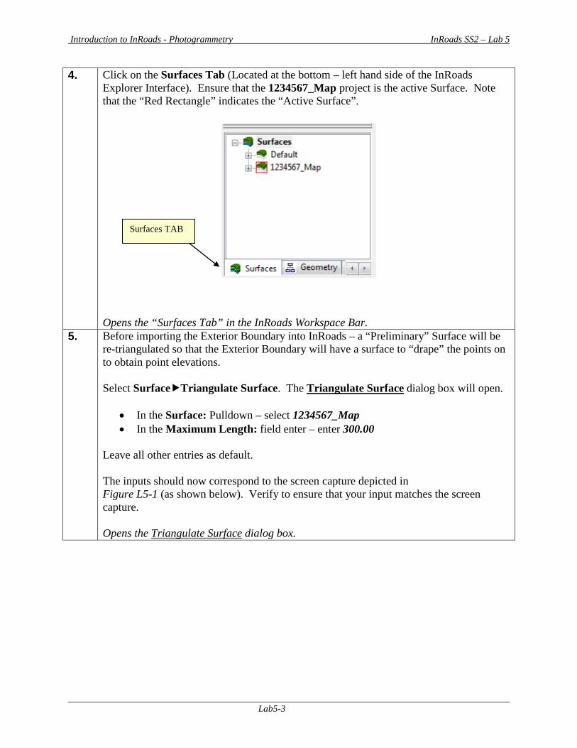
4. Click on the Surfaces Tab (Located at the bottom – left hand side of the InRoads Explorer Interface). Ensure that the 1234567_Map project is the active Surface. Note that the “Red Rectangle” indicates the “Active Surface”. Opens the “Surfaces Tab” in the InRoads Workspace Bar.
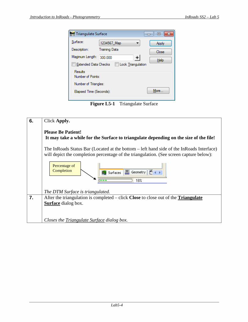
5. Before importing the Exterior Boundary into InRoads – a “Preliminary” Surface will be re-triangulated so that the Exterior Boundary will have a surface to “drape” the points on to obtain point elevations. Select SurfaceTriangulate Surface. The Triangulate Surface dialog box will open.
• In the Surface: Pulldown – select 1234567_Map • In the Maximum Length: field enter – enter 300.00
Leave all other entries as default. The inputs should now correspond to the screen capture depicted in Figure L5-1 (as shown below). Verify to ensure that your input matches the screen capture. Opens the Triangulate Surface dialog box.
Surfaces TAB
Introduction to InRoads - Photogrammetry InRoads SS2 – Lab 5
Lab5-4
Figure L5-1 Triangulate Surface
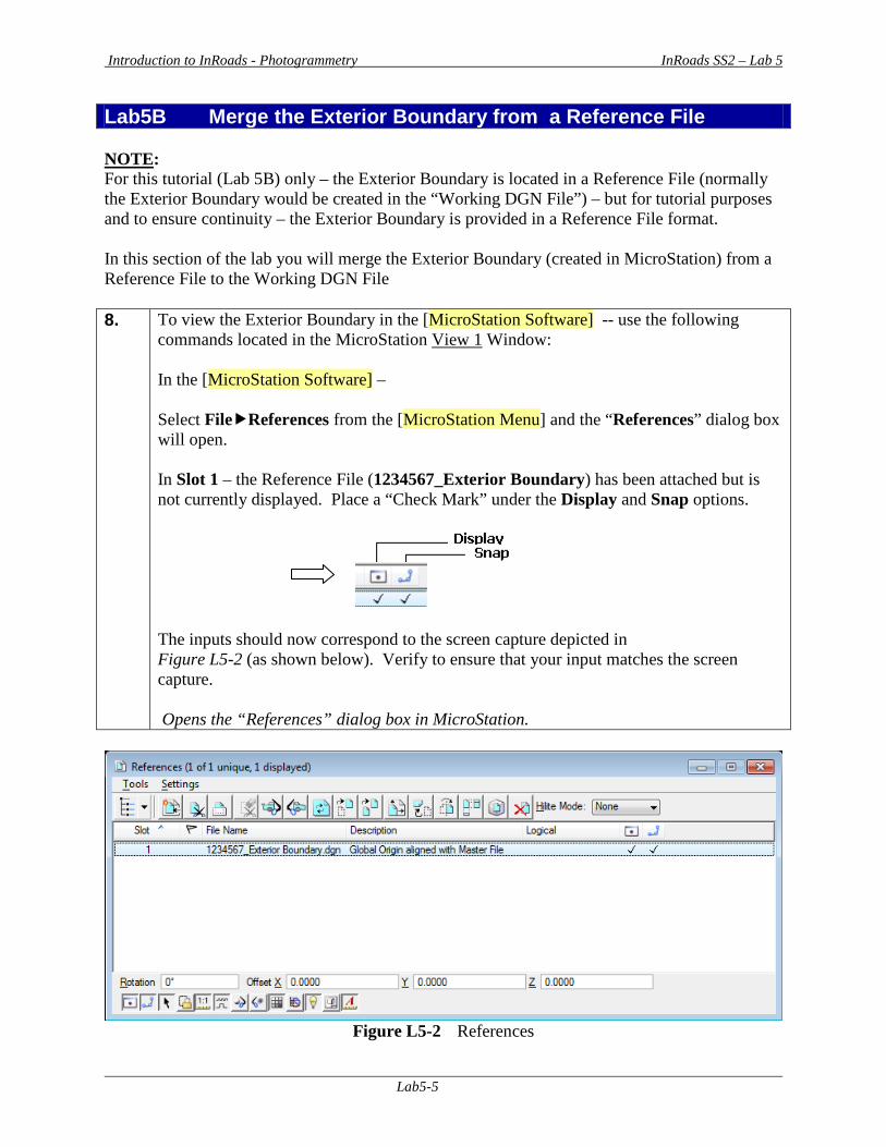
6. Click Apply. Please Be Patient! It may take a while for the Surface to triangulate depending on the size of the file! The InRoads Status Bar (Located at the bottom – left hand side of the InRoads Interface) will depict the completion percentage of the triangulation. (See screen capture below):
The DTM Surface is triangulated.
7. After the triangulation is completed – click Close to close out of the Triangulate Surface dialog box. Closes the Triangulate Surface dialog box.
Percentage of Completion
Introduction to InRoads - Photogrammetry InRoads SS2 – Lab 5
Lab5-5
Lab5B Merge the Exterior Boundary from a Reference File NOTE: For this tutorial (Lab 5B) only – the Exterior Boundary is located in a Reference File (normally the Exterior Boundary would be created in the “Working DGN File”) – but for tutorial purposes and to ensure continuity – the Exterior Boundary is provided in a Reference File format. In this section of the lab you will merge the Exterior Boundary (created in MicroStation) from a Reference File to the Working DGN File 8. To view the Exterior Boundary in the [MicroStation Software] -- use the following
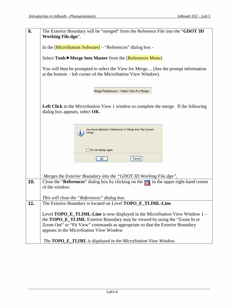
commands located in the MicroStation View 1 Window: In the [MicroStation Software] – Select FileReferences from the [MicroStation Menu] and the “References” dialog box will open. In Slot 1 – the Reference File (1234567_Exterior Boundary) has been attached but is not currently displayed. Place a “Check Mark” under the Display and Snap options. The inputs should now correspond to the screen capture depicted in Figure L5-2 (as shown below). Verify to ensure that your input matches the screen capture. Opens the “References” dialog box in MicroStation.
Figure L5-2 References
Introduction to InRoads - Photogrammetry InRoads SS2 – Lab 5
Lab5-6
9. The Exterior Boundary will be “merged” from the Reference File into the “GDOT 3D Working File.dgn”. In the [MicroStation Software] – “References” dialog box - Select ToolsMerge Into Master from the [References Menu]. You will then be prompted to select the View for Merge… (See the prompt information at the bottom – left corner of the MicroStation View Window). Left Click in the MicroStation View 1 window to complete the merge. If the following dialog box appears, select OK. Merges the Exterior Boundary into the “GDOT 3D Working File.dgn”.
10. Close the “References” dialog box by clicking on the in the upper right-hand corner of the window. This will close the “References” dialog box.
11. The Exterior Boundary is located on Level TOPO_E_TLIML-Line. Level TOPO_E_TLIML-Line is now displayed in the MicroStation View Window 1 – the TOPO_E_TLIML Exterior Boundary may be viewed by using the “Zoom In or Zoom Out” or “Fit View” commands as appropriate so that the Exterior Boundary appears in the MicroStation View Window The TOPO_E_TLIML is displayed in the MicroStation View Window.
Introduction to InRoads - Photogrammetry InRoads SS2 – Lab 5
Lab5-7
Lab5C Import the Exterior Boundary (TLIML) into InRoads In this section of the lab you will be importing the Exterior Boundary (the complex shape created in MicroStation) into the 1234567_Map.dtm Surface Project. The Exterior Boundary will be draped onto the triangulated surface in order to obtain point elevations (Delta Z). The Exterior Boundary will then be available for trimming of the extraneous triangles from the DTM Surface. (On a side note: The Interior Boundaries – TOPO_E_MOBSC Feature Style ---- Obscured Areas are tagged internally by InRoads to automatically be obscured. There is no extra step in the obscuring of interior areas of the DTM – these extraneous triangles are already trimmed). 12. In the [MicroStation Software] –
Select the “Zoom In or Zoom Out” or “Fit View” Icons as appropriate to view the Exterior Boundary.
13. Import the Exterior Boundary into InRoads In the InRoads Software: Select FileImportSurface from the InRoads Menu. The Import Surface dialog box will open. Select the “From Graphics” Tab.
• In the Surface: Pulldown – select 1234567_Map • In the Load From: Pulldown – select Single Element • In the Elevations: Pulldown – select Drape Surface • In the Intercept Surface: Pulldown – select 1234567_Map
In the Features Area of the dialog box:
• In the Seed Name: field – type the word MBOUNDARY (all upper case letters -- it is case sensitive)
• In the Feature Style: Pulldown – select TOPO_E_TLIML • In the Point Type: Pulldown – select Exterior • In the Duplicate Names: radio button – select Rename • In the Exclude from Triangulation: check box –
(Make sure there is NO Check Mark)
Leave all other entries as default. The inputs should now correspond to the screen capture depicted in Figure L5-3 (as shown below). Verify to ensure that your input matches the screen capture exactly. Opens the Import Surface dialog box allowing you to import an Exterior Boundary.
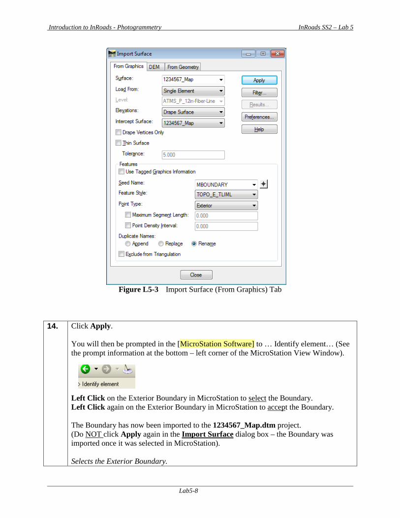
Introduction to InRoads - Photogrammetry InRoads SS2 – Lab 5
Lab5-8
Figure L5-3 Import Surface (From Graphics) Tab
14. Click Apply. You will then be prompted in the [MicroStation Software] to … Identify element… (See the prompt information at the bottom – left corner of the MicroStation View Window). Left Click on the Exterior Boundary in MicroStation to select the Boundary. Left Click again on the Exterior Boundary in MicroStation to accept the Boundary. The Boundary has now been imported to the 1234567_Map.dtm project. (Do NOT click Apply again in the Import Surface dialog box – the Boundary was imported once it was selected in MicroStation). Selects the Exterior Boundary.
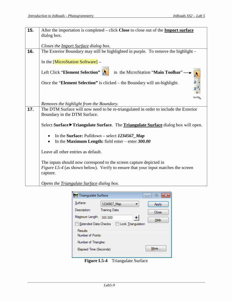
Introduction to InRoads - Photogrammetry InRoads SS2 – Lab 5
Lab5-9
15. After the importation is completed – click Close to close out of the Import surface dialog box. Closes the Import Surface dialog box.
16. The Exterior Boundary may still be highlighted in purple. To remove the highlight – In the [MicroStation Software] – Left Click “Element Selection” in the MicroStation “Main Toolbar” Once the “Element Selection” is clicked – the Boundary will un-highlight. Removes the highlight from the Boundary.
17. The DTM Surface will now need to be re-triangulated in order to include the Exterior Boundary in the DTM Surface. Select SurfaceTriangulate Surface. The Triangulate Surface dialog box will open.
• In the Surface: Pulldown – select 1234567_Map • In the Maximum Length: field enter – enter 300.00
Leave all other entries as default. The inputs should now correspond to the screen capture depicted in Figure L5-4 (as shown below). Verify to ensure that your input matches the screen capture. Opens the Triangulate Surface dialog box.
Figure L5-4 Triangulate Surface
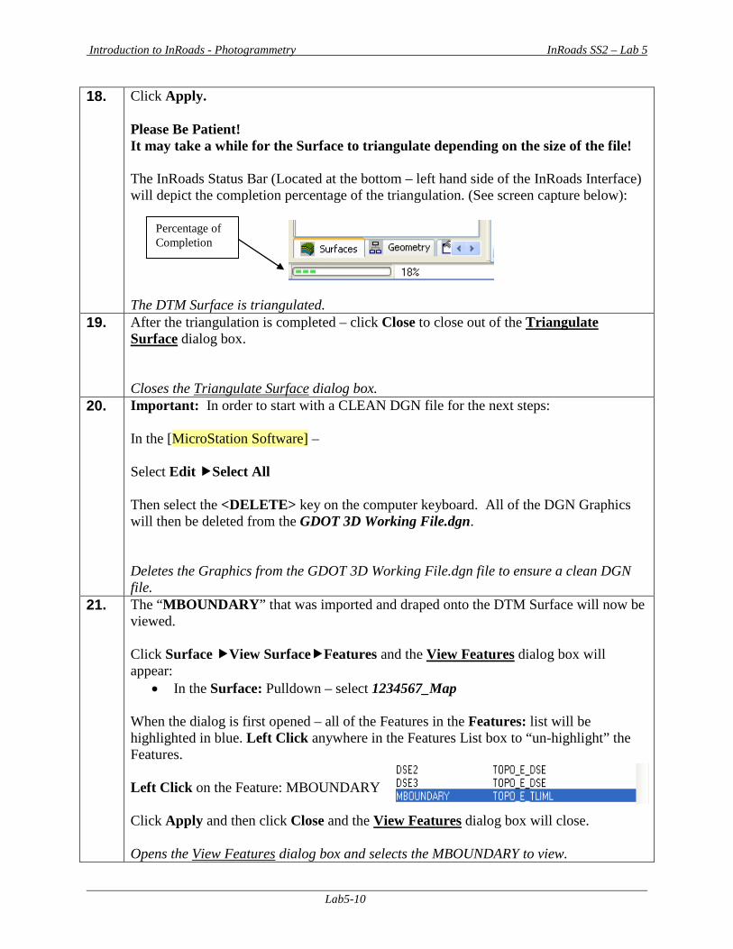
Introduction to InRoads - Photogrammetry InRoads SS2 – Lab 5
Lab5-10
18. Click Apply. Please Be Patient! It may take a while for the Surface to triangulate depending on the size of the file! The InRoads Status Bar (Located at the bottom – left hand side of the InRoads Interface) will depict the completion percentage of the triangulation. (See screen capture below):
The DTM Surface is triangulated.
19. After the triangulation is completed – click Close to close out of the Triangulate Surface dialog box. Closes the Triangulate Surface dialog box.
20. Important: In order to start with a CLEAN DGN file for the next steps: In the [MicroStation Software] – Select Edit Select All Then select the <DELETE> key on the computer keyboard. All of the DGN Graphics will then be deleted from the GDOT 3D Working File.dgn. Deletes the Graphics from the GDOT 3D Working File.dgn file to ensure a clean DGN file.
21. The “MBOUNDARY” that was imported and draped onto the DTM Surface will now be viewed. Click Surface View SurfaceFeatures and the View Features dialog box will appear:
• In the Surface: Pulldown – select 1234567_Map
When the dialog is first opened – all of the Features in the Features: list will be highlighted in blue. Left Click anywhere in the Features List box to “un-highlight” the Features. Left Click on the Feature: MBOUNDARY Click Apply and then click Close and the View Features dialog box will close. Opens the View Features dialog box and selects the MBOUNDARY to view.
Percentage of Completion
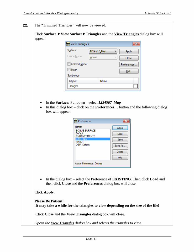
Introduction to InRoads - Photogrammetry InRoads SS2 – Lab 5
Lab5-11
22. The “Trimmed Triangles” will now be viewed. Click Surface View SurfaceTriangles and the View Triangles dialog box will appear:
• In the Surface: Pulldown – select 1234567_Map • In this dialog box – click on the Preferences… button and the following dialog
box will appear:
• In the dialog box – select the Preference of EXISTING. Then click Load and then click Close and the Preferences dialog box will close.
Click Apply. Please Be Patient! It may take a while for the triangles to view depending on the size of the file! Click Close and the View Triangles dialog box will close. Opens the View Triangles dialog box and selects the triangles to view.
Introduction to InRoads - Photogrammetry InRoads SS2 – Lab 5
Lab5-12
23. In the [MicroStation Software] – Select the “Zoom In or Zoom Out” or “Fit View” commands as appropriate to view the MBOUNDARY and the triangles. NOTICE: When reviewing the DTM Surface – note that the Interior Boundaries have already been obscured in the DTM. The following is not a required step: But -- if desired - the TOPO_E_MOBSC Features may be viewed as well by using the Surface View SurfaceFeatures command and selecting the MOBSC Features (Obscured Feature Style) to view. Views the MBOUNDARY and triangles.
24. Save the InRoads Surface File Even though the Exterior Boundary has been imported into InRoads – the data has not yet been saved. As mentioned previously, InRoads retains the data in temporary memory but does not save the data on the fly. Whenever a change has been made to an InRoads Surface Project – Save the project and its associated modifications or changes. Select FileSave Surface from the InRoads Menu. Please Note: (The “Save As” dialog box may not appear because the Surface has already been saved initially). The Surface Project (1234567_Map.dtm) will be saved to Lab 5 in the following path: C:\InRoads Data\1234567\Photogrammetry Labs\Lab5 Note that the InRoads and MicroStation Status Bar (Located at the bottom of both the InRoads and MicroStation Interface) will depict a message when the Surface Project has been saved. The 1234567_Map Surface Project has now been saved to the following path: C:\InRoads Data\1234567\Photogrammetry Labs\Lab5
Introduction to InRoads - Photogrammetry InRoads SS2 – Lab 5
Lab5-13
25. Important Step: In order to Start with a CLEAN DGN file for the next Lab (Lab 6): In the [MicroStation Software] – Select Edit Select All Then select the <DELETE> key on the computer keyboard. All of the DGN Graphics will then be deleted from the GDOT 3D Working File.dgn. Deletes the Graphics from the GDOT 3D Working File.dgn file to ensure a clean DGN file for the next Lab.
26. This concludes Lab 5. Do not proceed until the Instructor directs you to do so.

Introduction to InRoads - Photogrammetry InRoads SS2 – Lab 6
Lab6-1
Lab 6 Resolve DTM Errors
Objective After the Exterior Boundary has been incorporated into the DTM – the final processing of the DTM Surface can begin. The Exterior and Interior Boundaries have already been included into the DTM to ensure that all of the appropriate extraneous triangles and obscured areas are trimmed and/or obscured. The Crossing Segments have also been resolved. The next step in the process is to review the DTM Surface to ensure that there is no erroneous or “bad” data included in the DTM. This review will determine if there are any elevations that are incorrect or bad shots that were picked up. The DTM will be reviewed in a 3D environment as a “shaded model” to assist in the resolutions of any “spikes” or erroneous data. This Lab will examine the process of resolving any “spikes” or bad data in the DTM Surface and review/resolve any crossing segments which may have been introduced when the Exterior Boundary was incorporated, etc. The objective of Lab 6 is to:
• Review the DTM Surface as a shaded 3D model and check for any erroneous or “bad” data.
• Resolve any “spikes” or incorrect Mapping Data • Review to ensure that no segment crossings have been introduced in the Surface
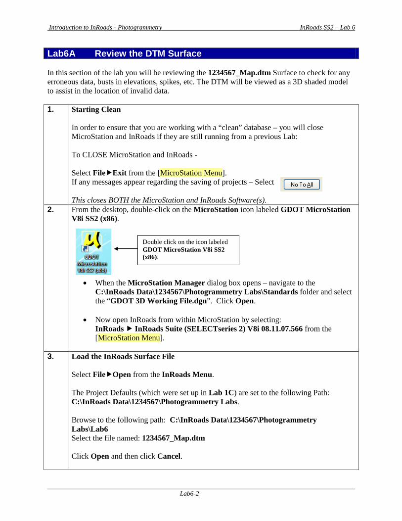
Introduction to InRoads - Photogrammetry InRoads SS2 – Lab 6
Lab6-2
Lab6A Review the DTM Surface In this section of the lab you will be reviewing the 1234567_Map.dtm Surface to check for any erroneous data, busts in elevations, spikes, etc. The DTM will be viewed as a 3D shaded model to assist in the location of invalid data. 1. Starting Clean
In order to ensure that you are working with a “clean” database – you will close MicroStation and InRoads if they are still running from a previous Lab: To CLOSE MicroStation and InRoads - Select FileExit from the [MicroStation Menu]. If any messages appear regarding the saving of projects – Select This closes BOTH the MicroStation and InRoads Software(s).
2. From the desktop, double-click on the MicroStation icon labeled GDOT MicroStation V8i SS2 (x86).
• When the MicroStation Manager dialog box opens – navigate to the C:\InRoads Data\1234567\Photogrammetry Labs\Standards folder and select the “GDOT 3D Working File.dgn”. Click Open.
• Now open InRoads from within MicroStation by selecting:
InRoads InRoads Suite (SELECTseries 2) V8i 08.11.07.566 from the [MicroStation Menu].
3. Load the InRoads Surface File
Select FileOpen from the InRoads Menu. The Project Defaults (which were set up in Lab 1C) are set to the following Path: C:\InRoads Data\1234567\Photogrammetry Labs. Browse to the following path: C:\InRoads Data\1234567\Photogrammetry Labs\Lab6 Select the file named: 1234567_Map.dtm Click Open and then click Cancel.
Double click on the icon labeled GDOT MicroStation V8i SS2 (x86).
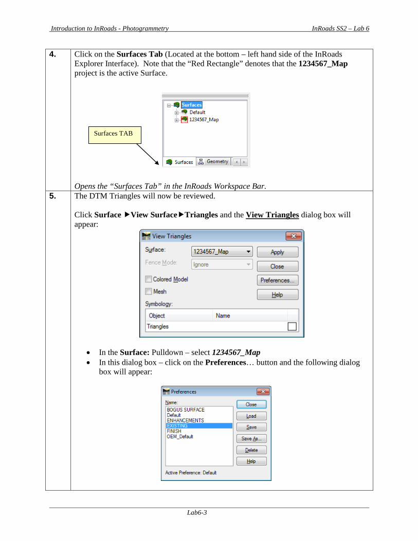
Introduction to InRoads - Photogrammetry InRoads SS2 – Lab 6
Lab6-3
4. Click on the Surfaces Tab (Located at the bottom – left hand side of the InRoads Explorer Interface). Note that the “Red Rectangle” denotes that the 1234567_Map project is the active Surface. Opens the “Surfaces Tab” in the InRoads Workspace Bar.
5. The DTM Triangles will now be reviewed. Click Surface View SurfaceTriangles and the View Triangles dialog box will appear:
• In the Surface: Pulldown – select 1234567_Map • In this dialog box – click on the Preferences… button and the following dialog
box will appear:
Surfaces TAB

Introduction to InRoads - Photogrammetry InRoads SS2 – Lab 6
Lab6-4
• In the dialog box – select the Preference of EXISTING. Then click Load and
then click Close and the Preferences dialog box will close. Click Apply. Please Be Patient! It may take a while for the triangles to view depending on the size of the file! (See the Example screen capture depicted below in Figure L6-1). Opens the View Triangles dialog box and selects the triangles to view.
Figure L6-1 Wireframe Triangles
6. Click Close and the View Triangles dialog box will close.
Closes the View Triangles dialog box.
7. In order to review the DTM Surface – the user must become familiar with the appropriate settings and commands to utilize in MicroStation. A good resource for this information is the “MicroStation Help Files” which is located in the [MicroStation Menu] under HelpContents. Please refer to this resource for additional information. Refers to the location for the MicroStation “Help Files”.
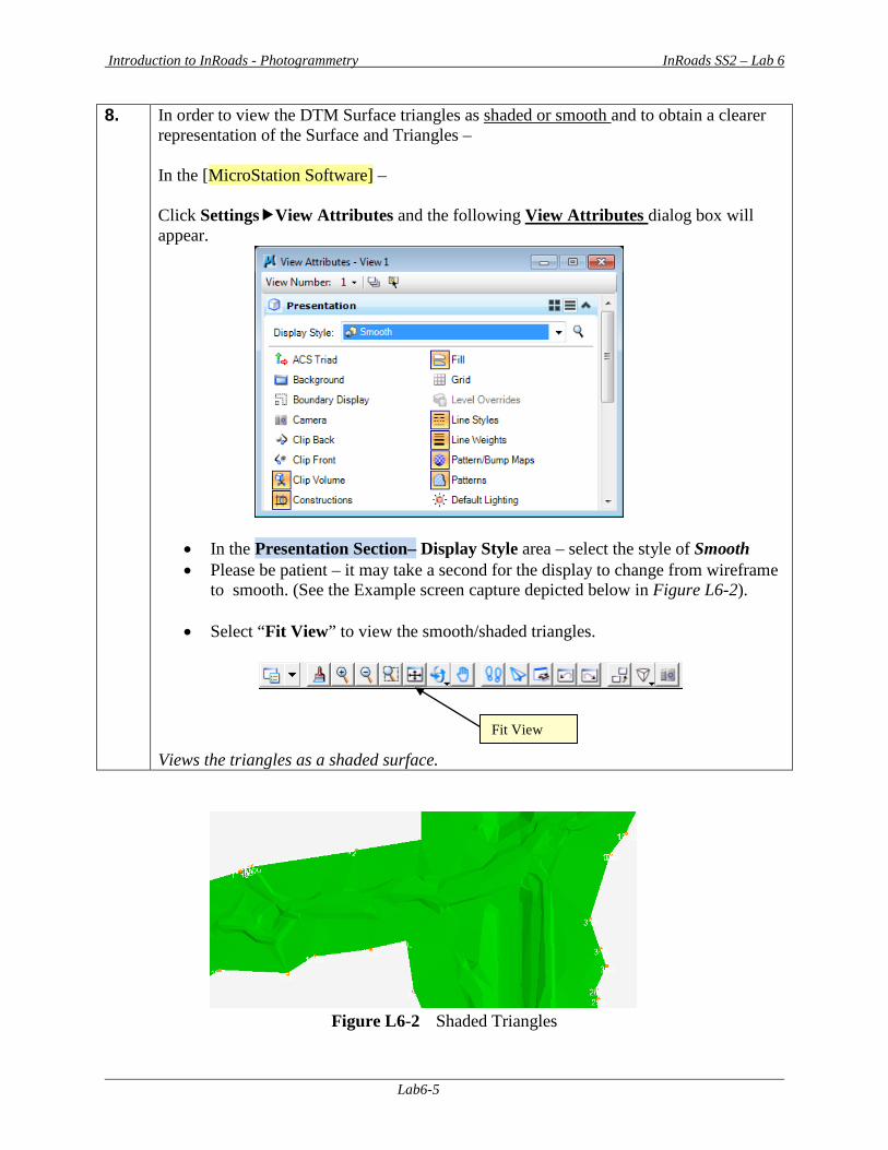
Introduction to InRoads - Photogrammetry InRoads SS2 – Lab 6
Lab6-5
8. In order to view the DTM Surface triangles as shaded or smooth and to obtain a clearer representation of the Surface and Triangles – In the [MicroStation Software] – Click SettingsView Attributes and the following View Attributes dialog box will appear.
• In the Presentation Section– Display Style area – select the style of Smooth • Please be patient – it may take a second for the display to change from wireframe
to smooth. (See the Example screen capture depicted below in Figure L6-2).
• Select “Fit View” to view the smooth/shaded triangles.
Views the triangles as a shaded surface.
Figure L6-2 Shaded Triangles
Fit View
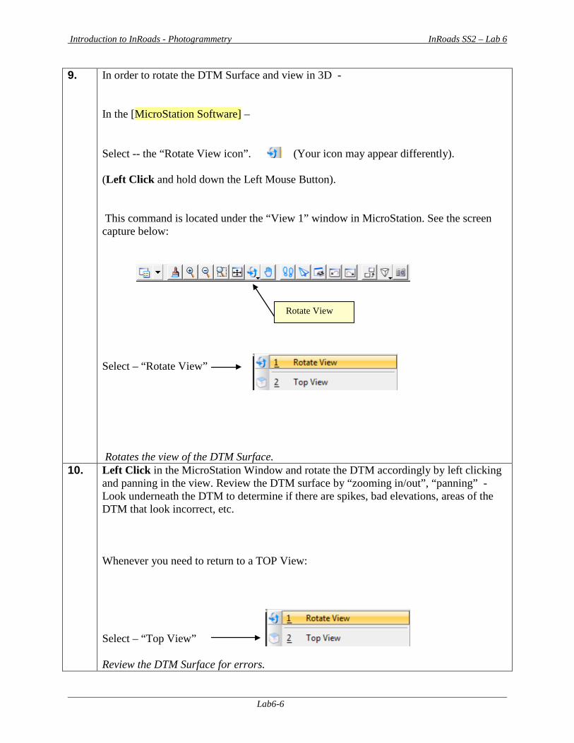
Introduction to InRoads - Photogrammetry InRoads SS2 – Lab 6
Lab6-6
9. In order to rotate the DTM Surface and view in 3D - In the [MicroStation Software] – Select -- the “Rotate View icon”. (Your icon may appear differently). (Left Click and hold down the Left Mouse Button). This command is located under the “View 1” window in MicroStation. See the screen capture below:
Select – “Rotate View” Rotates the view of the DTM Surface.
10. Left Click in the MicroStation Window and rotate the DTM accordingly by left clicking and panning in the view. Review the DTM surface by “zooming in/out”, “panning” - Look underneath the DTM to determine if there are spikes, bad elevations, areas of the DTM that look incorrect, etc. Whenever you need to return to a TOP View: Select – “Top View” Review the DTM Surface for errors.
Rotate View
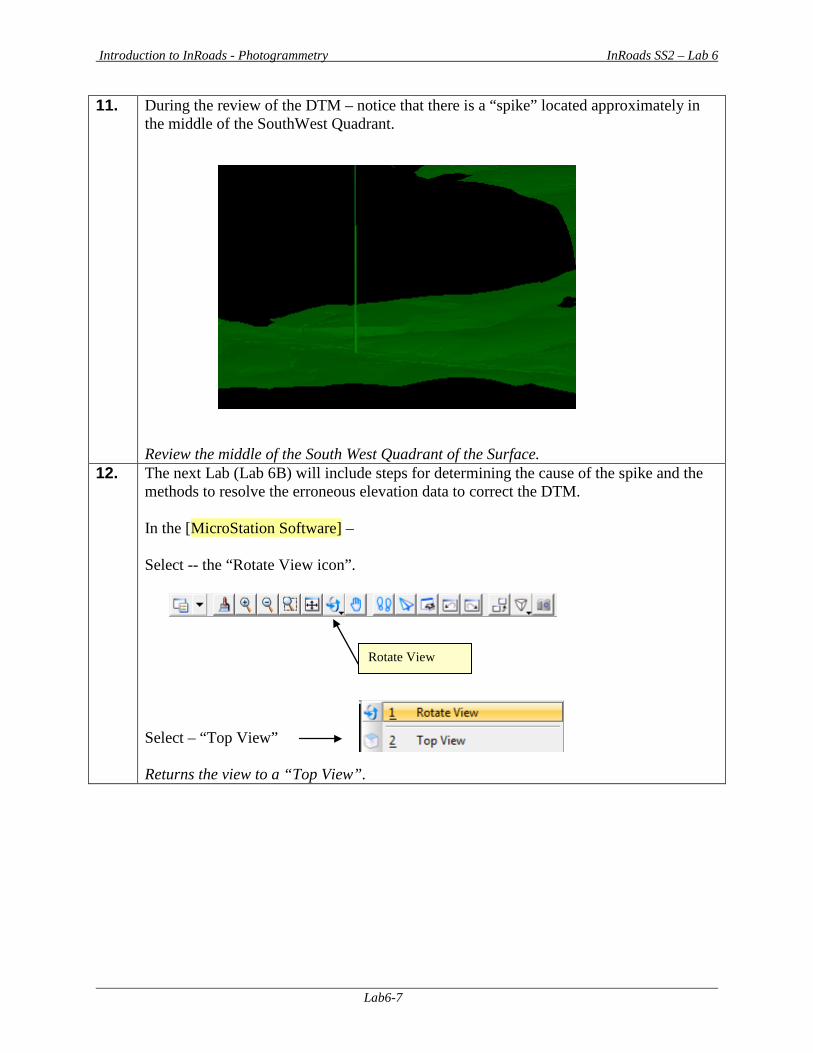
Introduction to InRoads - Photogrammetry InRoads SS2 – Lab 6
Lab6-7
11. During the review of the DTM – notice that there is a “spike” located approximately in the middle of the SouthWest Quadrant. Review the middle of the South West Quadrant of the Surface.
12. The next Lab (Lab 6B) will include steps for determining the cause of the spike and the methods to resolve the erroneous elevation data to correct the DTM. In the [MicroStation Software] – Select -- the “Rotate View icon”.
Select – “Top View” Returns the view to a “Top View”.
Rotate View
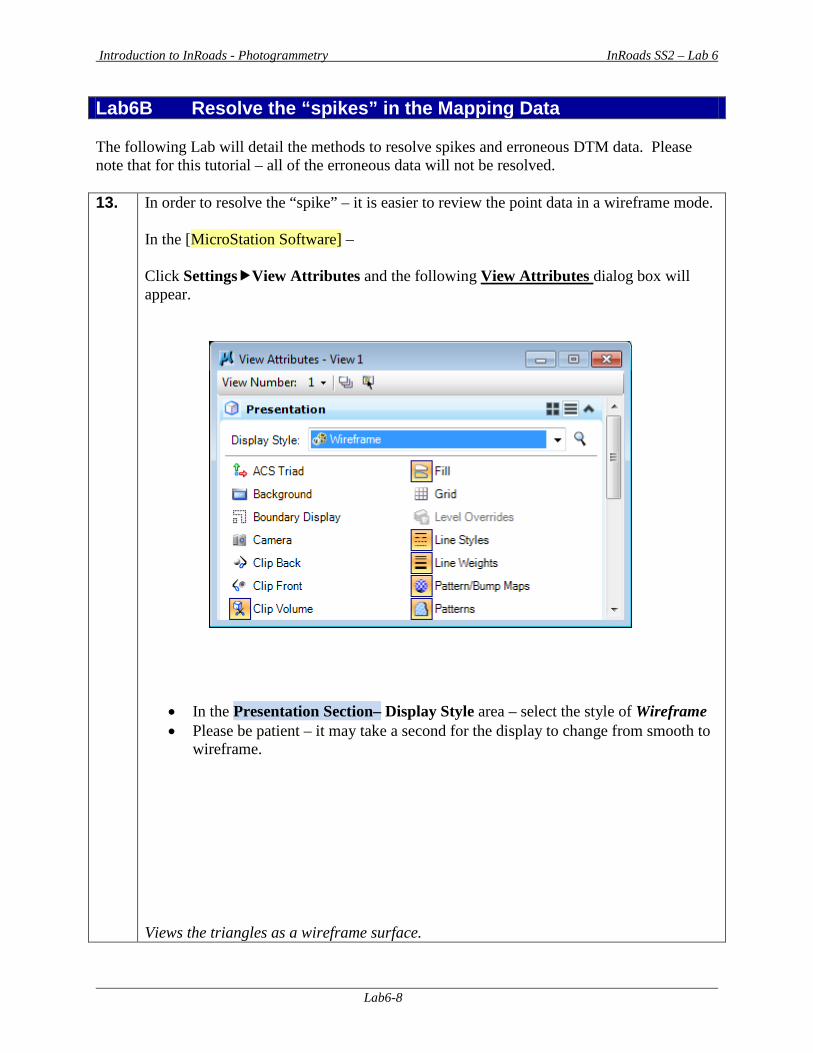
Introduction to InRoads - Photogrammetry InRoads SS2 – Lab 6
Lab6-8
Lab6B Resolve the “spikes” in the Mapping Data The following Lab will detail the methods to resolve spikes and erroneous DTM data. Please note that for this tutorial – all of the erroneous data will not be resolved. 13. In order to resolve the “spike” – it is easier to review the point data in a wireframe mode.
In the [MicroStation Software] – Click SettingsView Attributes and the following View Attributes dialog box will appear.
• In the Presentation Section– Display Style area – select the style of Wireframe • Please be patient – it may take a second for the display to change from smooth to
wireframe. Views the triangles as a wireframe surface.
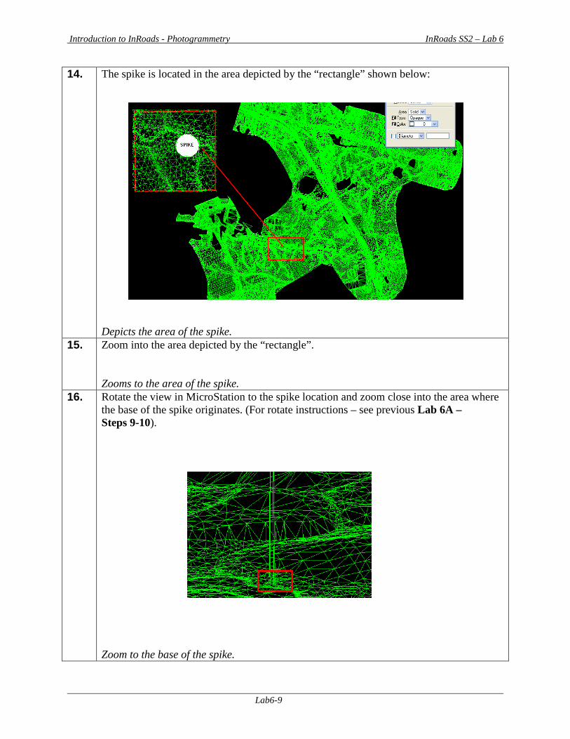
Introduction to InRoads - Photogrammetry InRoads SS2 – Lab 6
Lab6-9
14. The spike is located in the area depicted by the “rectangle” shown below: Depicts the area of the spike.
15. Zoom into the area depicted by the “rectangle”. Zooms to the area of the spike.
16. Rotate the view in MicroStation to the spike location and zoom close into the area where the base of the spike originates. (For rotate instructions – see previous Lab 6A – Steps 9-10). Zoom to the base of the spike.
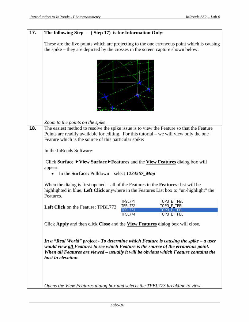
Introduction to InRoads - Photogrammetry InRoads SS2 – Lab 6
Lab6-10
17. The following Step --- ( Step 17) is for Information Only: These are the five points which are projecting to the one erroneous point which is causing the spike – they are depicted by the crosses in the screen capture shown below: Zoom to the points on the spike.
18. The easiest method to resolve the spike issue is to view the Feature so that the Feature Points are readily available for editing. For this tutorial – we will view only the one Feature which is the source of this particular spike: In the InRoads Software: Click Surface View SurfaceFeatures and the View Features dialog box will appear:
• In the Surface: Pulldown – select 1234567_Map
When the dialog is first opened – all of the Features in the Features: list will be highlighted in blue. Left Click anywhere in the Features List box to “un-highlight” the Features. Left Click on the Feature: TPBL773 Click Apply and then click Close and the View Features dialog box will close. In a “Real World” project - To determine which Feature is causing the spike – a user would view all Features to see which Feature is the source of the erroneous point. When all Features are viewed – usually it will be obvious which Feature contains the bust in elevation. Opens the View Features dialog box and selects the TPBL773 breakline to view.
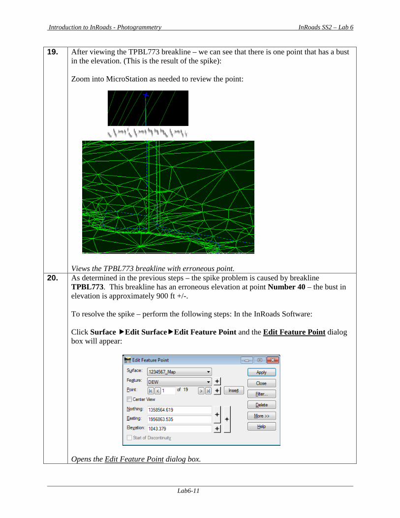
Introduction to InRoads - Photogrammetry InRoads SS2 – Lab 6
Lab6-11
19. After viewing the TPBL773 breakline – we can see that there is one point that has a bust in the elevation. (This is the result of the spike): Zoom into MicroStation as needed to review the point: Views the TPBL773 breakline with erroneous point.
20. As determined in the previous steps – the spike problem is caused by breakline TPBL773. This breakline has an erroneous elevation at point Number 40 – the bust in elevation is approximately 900 ft +/-. To resolve the spike – perform the following steps: In the InRoads Software: Click Surface Edit SurfaceEdit Feature Point and the Edit Feature Point dialog box will appear:
Opens the Edit Feature Point dialog box.
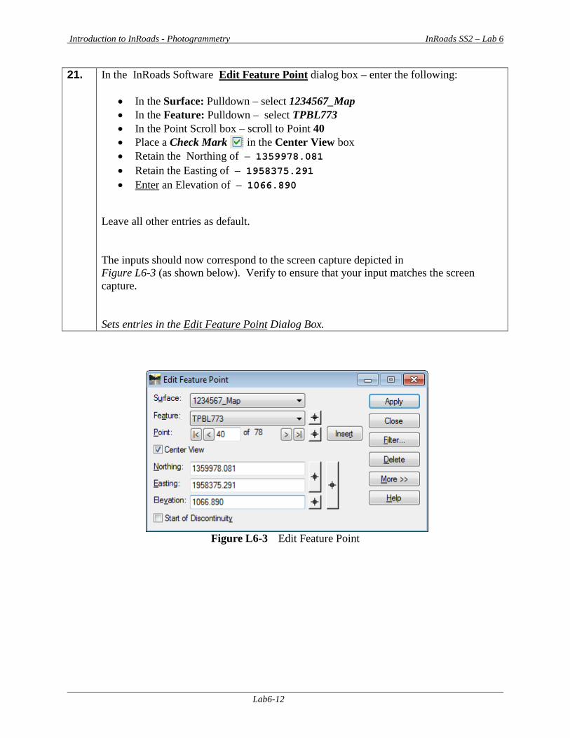
Introduction to InRoads - Photogrammetry InRoads SS2 – Lab 6
Lab6-12
21. In the InRoads Software Edit Feature Point dialog box – enter the following:
• In the Surface: Pulldown – select 1234567_Map • In the Feature: Pulldown – select TPBL773 • In the Point Scroll box – scroll to Point 40 • Place a Check Mark in the Center View box • Retain the Northing of – 1359978.081 • Retain the Easting of – 1958375.291 • Enter an Elevation of – 1066.890
Leave all other entries as default. The inputs should now correspond to the screen capture depicted in Figure L6-3 (as shown below). Verify to ensure that your input matches the screen capture. Sets entries in the Edit Feature Point Dialog Box.
Figure L6-3 Edit Feature Point
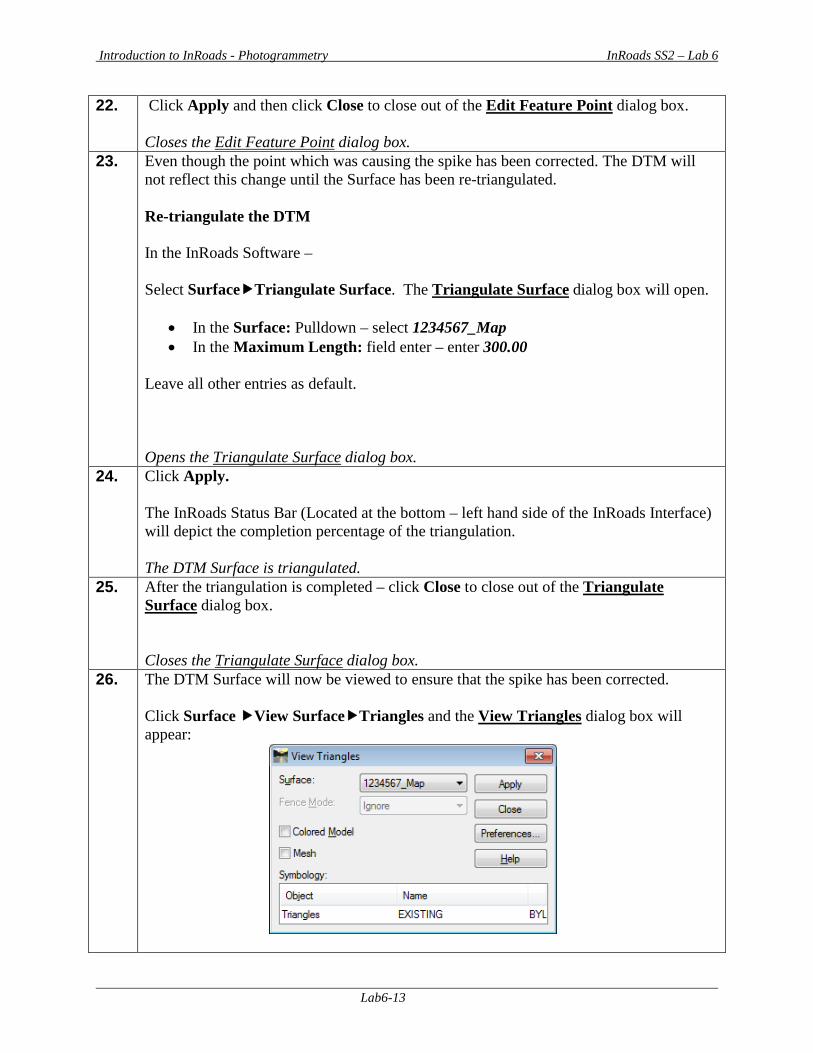
Introduction to InRoads - Photogrammetry InRoads SS2 – Lab 6
Lab6-13
22. Click Apply and then click Close to close out of the Edit Feature Point dialog box. Closes the Edit Feature Point dialog box.
23. Even though the point which was causing the spike has been corrected. The DTM will not reflect this change until the Surface has been re-triangulated. Re-triangulate the DTM In the InRoads Software – Select SurfaceTriangulate Surface. The Triangulate Surface dialog box will open.
• In the Surface: Pulldown – select 1234567_Map • In the Maximum Length: field enter – enter 300.00
Leave all other entries as default. Opens the Triangulate Surface dialog box.
24. Click Apply. The InRoads Status Bar (Located at the bottom – left hand side of the InRoads Interface) will depict the completion percentage of the triangulation. The DTM Surface is triangulated.
25. After the triangulation is completed – click Close to close out of the Triangulate Surface dialog box. Closes the Triangulate Surface dialog box.
26. The DTM Surface will now be viewed to ensure that the spike has been corrected. Click Surface View SurfaceTriangles and the View Triangles dialog box will appear:
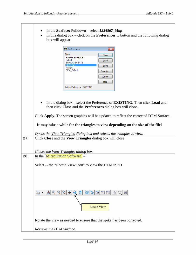
Introduction to InRoads - Photogrammetry InRoads SS2 – Lab 6
Lab6-14
• In the Surface: Pulldown – select 1234567_Map • In this dialog box – click on the Preferences… button and the following dialog
box will appear:
• In the dialog box – select the Preference of EXISTING. Then click Load and then click Close and the Preferences dialog box will close.
Click Apply. The screen graphics will be updated to reflect the corrected DTM Surface. It may take a while for the triangles to view depending on the size of the file! Opens the View Triangles dialog box and selects the triangles to view.
27. Click Close and the View Triangles dialog box will close. Closes the View Triangles dialog box.
28. In the [MicroStation Software] – Select -- the “Rotate View icon” to view the DTM in 3D.
Rotate the view as needed to ensure that the spike has been corrected. Reviews the DTM Surface.
Rotate View
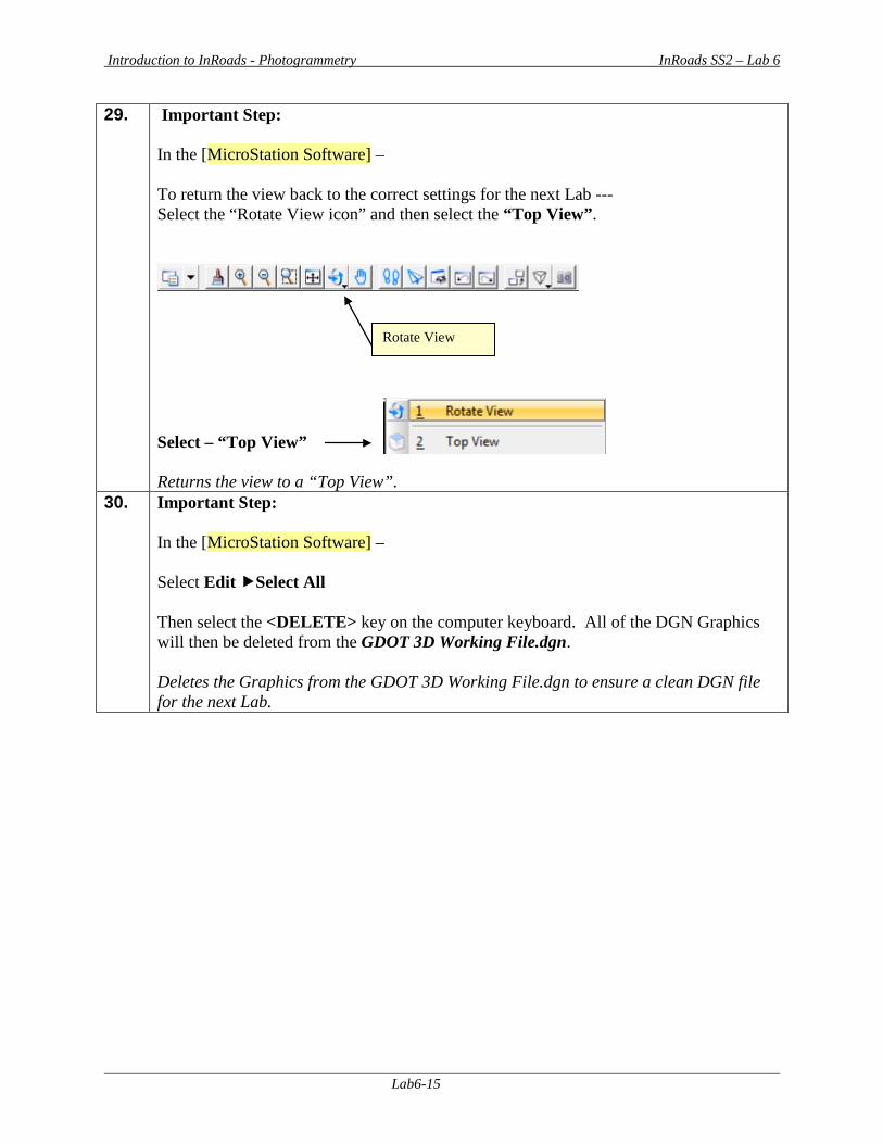
Introduction to InRoads - Photogrammetry InRoads SS2 – Lab 6
Lab6-15
29. Important Step: In the [MicroStation Software] – To return the view back to the correct settings for the next Lab --- Select the “Rotate View icon” and then select the “Top View”.
Select – “Top View” Returns the view to a “Top View”.
30. Important Step: In the [MicroStation Software] – Select Edit Select All Then select the <DELETE> key on the computer keyboard. All of the DGN Graphics will then be deleted from the GDOT 3D Working File.dgn. Deletes the Graphics from the GDOT 3D Working File.dgn to ensure a clean DGN file for the next Lab.
Rotate View
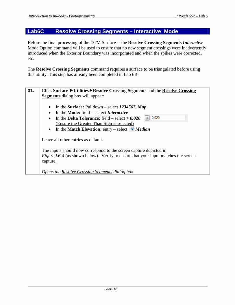
Introduction to InRoads - Photogrammetry InRoads SS2 – Lab 6
Lab6-16
Lab6C Resolve Crossing Segments – Interactive Mode Before the final processing of the DTM Surface -- the Resolve Crossing Segments Interactive Mode Option command will be used to ensure that no new segment crossings were inadvertently introduced when the Exterior Boundary was incorporated and when the spikes were corrected, etc. The Resolve Crossing Segments command requires a surface to be triangulated before using this utility. This step has already been completed in Lab 6B. 31. Click Surface UtilitiesResolve Crossing Segments and the Resolve Crossing
Segments dialog box will appear:
• In the Surface: Pulldown – select 1234567_Map • In the Mode: field – select Interactive • In the Delta Tolerance: field – select > 0.020
(Ensure the Greater Than Sign is selected) • In the Match Elevation: entry – select Median
Leave all other entries as default. The inputs should now correspond to the screen capture depicted in Figure L6-4 (as shown below). Verify to ensure that your input matches the screen capture. Opens the Resolve Crossing Segments dialog box
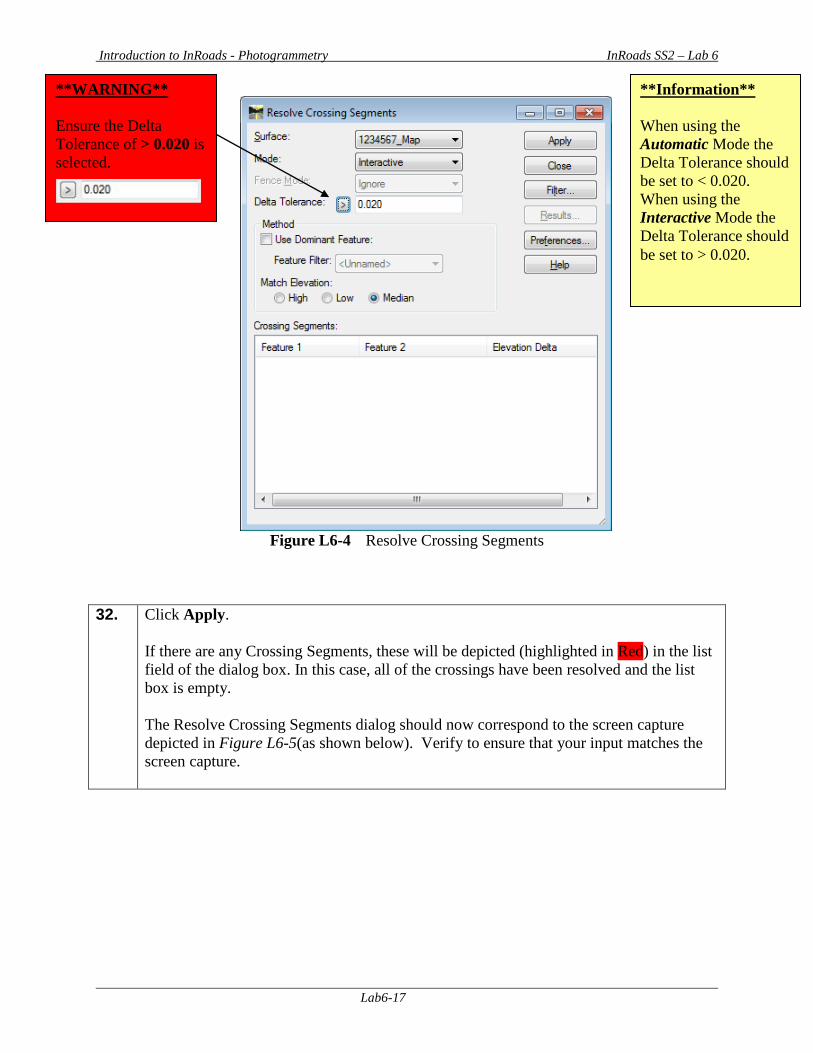
Introduction to InRoads - Photogrammetry InRoads SS2 – Lab 6
Lab6-17
Figure L6-4 Resolve Crossing Segments
32. Click Apply. If there are any Crossing Segments, these will be depicted (highlighted in Red) in the list field of the dialog box. In this case, all of the crossings have been resolved and the list box is empty. The Resolve Crossing Segments dialog should now correspond to the screen capture depicted in Figure L6-5(as shown below). Verify to ensure that your input matches the screen capture.
**WARNING** Ensure the Delta Tolerance of > 0.020 is selected.
**Information** When using the Automatic Mode the Delta Tolerance should be set to < 0.020. When using the Interactive Mode the Delta Tolerance should be set to > 0.020.
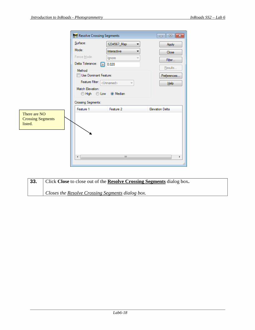
Introduction to InRoads - Photogrammetry InRoads SS2 – Lab 6
Lab6-18
33. Click Close to close out of the Resolve Crossing Segments dialog box.
Closes the Resolve Crossing Segments dialog box.
There are NO Crossing Segments listed.
Introduction to InRoads - Photogrammetry InRoads SS2 – Lab 6
Lab6-19
34. In a “Real World” project - if Crossing Segments had been introduced – the user could refer back to Lab 3 for detailed Resolve Crossing Segments information and then proceed with the steps accordingly before final processing of the DTM. Save the InRoads Surface File Even though the “spikes” and errors have been corrected – the data has not yet been saved. InRoads retains the data in temporary memory but does not save the data on the fly. When a change has been made to an InRoads Surface Project – Save the project. Select FileSave Surface from the InRoads Menu. Please Note: (The “Save As” dialog box may not appear because the Surface has already been saved initially). The Surface Project (1234567_Map.dtm) will be saved to Lab 6 in the following path: C:\InRoads Data\1234567\Photogrammetry Labs\Lab6 Note that the InRoads and MicroStation Status Bar (Located at the bottom of both the InRoads and MicroStation Interface) will depict a message when the Surface Project has been saved. The 1234567_Map Surface Project has now been saved to the following path: C:\InRoads Data\1234567\Photogrammetry Labs\Lab6
35. Important Step: In order to Start with a CLEAN DGN file for the next Lab (Lab 7): In the [MicroStation Software] – Select Edit Select All Then select the <DELETE> key on the computer keyboard. All of the DGN Graphics will then be deleted from the GDOT 3D Working File.dgn. Deletes the Graphics from the GDOT 3D Working File.dgn file to ensure a clean DGN file for the next Lab.
36. This concludes Lab 6. Do not proceed until the Instructor directs you to do so.

Introduction to InRoads - Photogrammetry InRoads SS2 – Lab 7
Lab7-1
Lab 7 Final Processing of the Mapping Surface
Objective The DTM Surface data has been verified and all database errors have been corrected in the previous Lab. The next step is the completion of the final processing of the DTM Surface. The DTM Surface will be re-triangulated and compressed (which will release memory slots that contain deleted data). The Topographical Mapping DGN file generated from Softcopy will be included along with the processed DTM Surface as the final deliverables for submission to the District Survey Data Engineers. The Final Deliverables include the following:
• A processed DTM Surface file (PI#_Map.dtm) • A topographical DGN file (PI#_Map.dgn) • DGN Plot Files (.pdf) • Mapping Photographs • A Roll Plot of the topographical DGN data (if required) • A Photogrammetry Quality Assurance Checklist Document
The objective of Lab 7 is to:
• Process a completed DTM Surface File • Generate the deliverables for submission to the Districts.
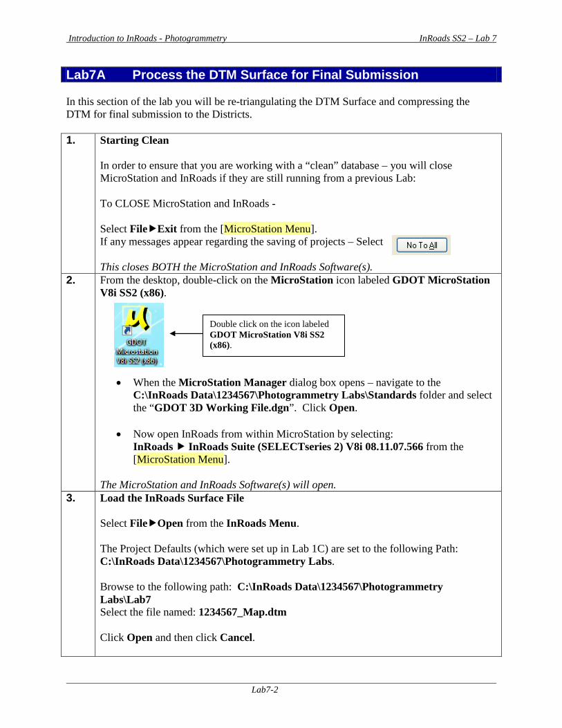
Introduction to InRoads - Photogrammetry InRoads SS2 – Lab 7
Lab7-2
Lab7A Process the DTM Surface for Final Submission In this section of the lab you will be re-triangulating the DTM Surface and compressing the DTM for final submission to the Districts. 1. Starting Clean
In order to ensure that you are working with a “clean” database – you will close MicroStation and InRoads if they are still running from a previous Lab: To CLOSE MicroStation and InRoads - Select FileExit from the [MicroStation Menu]. If any messages appear regarding the saving of projects – Select This closes BOTH the MicroStation and InRoads Software(s).
2. From the desktop, double-click on the MicroStation icon labeled GDOT MicroStation V8i SS2 (x86).
• When the MicroStation Manager dialog box opens – navigate to the C:\InRoads Data\1234567\Photogrammetry Labs\Standards folder and select the “GDOT 3D Working File.dgn”. Click Open.
• Now open InRoads from within MicroStation by selecting:
InRoads InRoads Suite (SELECTseries 2) V8i 08.11.07.566 from the [MicroStation Menu].
The MicroStation and InRoads Software(s) will open.
3. Load the InRoads Surface File Select FileOpen from the InRoads Menu. The Project Defaults (which were set up in Lab 1C) are set to the following Path: C:\InRoads Data\1234567\Photogrammetry Labs. Browse to the following path: C:\InRoads Data\1234567\Photogrammetry Labs\Lab7 Select the file named: 1234567_Map.dtm Click Open and then click Cancel.
Double click on the icon labeled GDOT MicroStation V8i SS2 (x86).
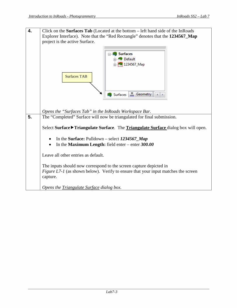
Introduction to InRoads - Photogrammetry InRoads SS2 – Lab 7
Lab7-3
4. Click on the Surfaces Tab (Located at the bottom – left hand side of the InRoads Explorer Interface). Note that the “Red Rectangle” denotes that the 1234567_Map project is the active Surface. Opens the “Surfaces Tab” in the InRoads Workspace Bar.
5. The “Completed” Surface will now be triangulated for final submission. Select SurfaceTriangulate Surface. The Triangulate Surface dialog box will open.
• In the Surface: Pulldown – select 1234567_Map • In the Maximum Length: field enter – enter 300.00
Leave all other entries as default. The inputs should now correspond to the screen capture depicted in Figure L7-1 (as shown below). Verify to ensure that your input matches the screen capture. Opens the Triangulate Surface dialog box.
Surfaces TAB
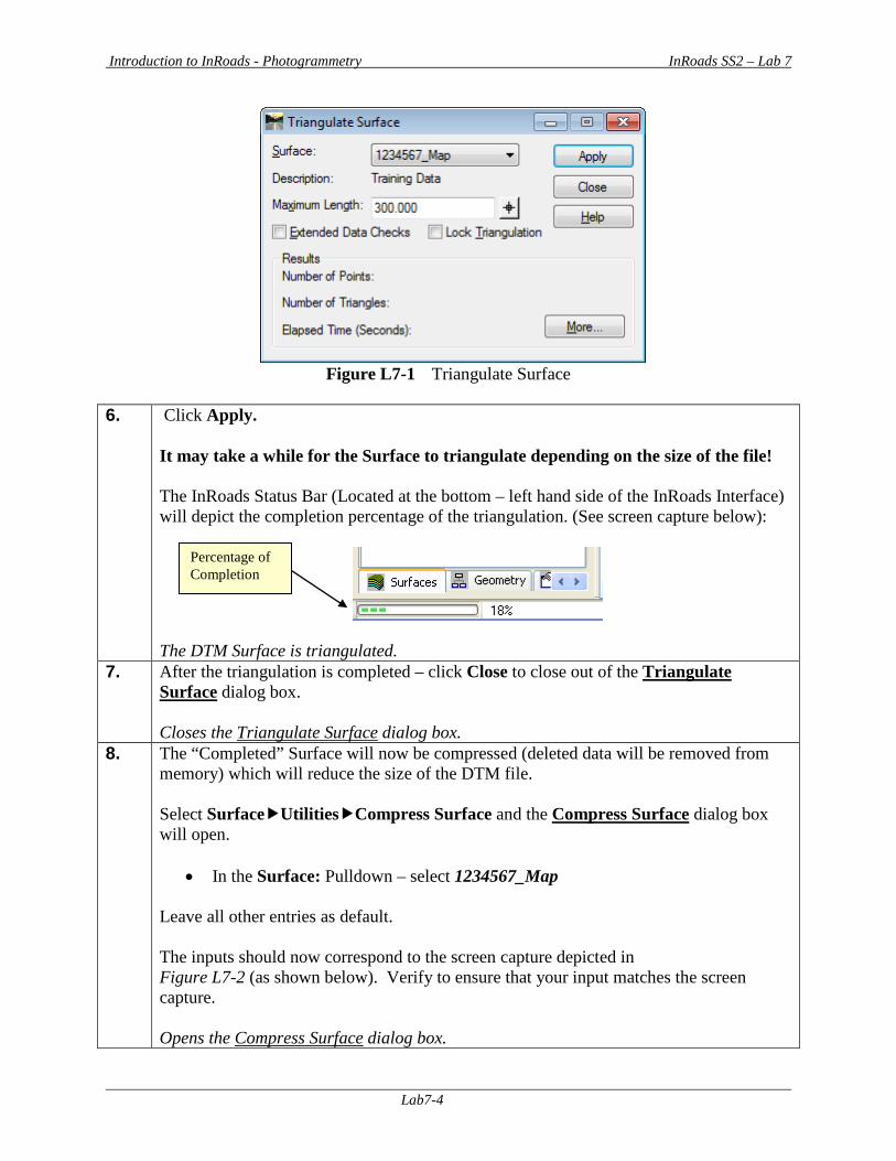
Introduction to InRoads - Photogrammetry InRoads SS2 – Lab 7
Lab7-4
Figure L7-1 Triangulate Surface
6. Click Apply.
It may take a while for the Surface to triangulate depending on the size of the file! The InRoads Status Bar (Located at the bottom – left hand side of the InRoads Interface) will depict the completion percentage of the triangulation. (See screen capture below):
The DTM Surface is triangulated.
7. After the triangulation is completed – click Close to close out of the Triangulate Surface dialog box. Closes the Triangulate Surface dialog box.
8. The “Completed” Surface will now be compressed (deleted data will be removed from memory) which will reduce the size of the DTM file. Select SurfaceUtilitiesCompress Surface and the Compress Surface dialog box will open.
• In the Surface: Pulldown – select 1234567_Map
Leave all other entries as default. The inputs should now correspond to the screen capture depicted in Figure L7-2 (as shown below). Verify to ensure that your input matches the screen capture. Opens the Compress Surface dialog box.
Percentage of Completion
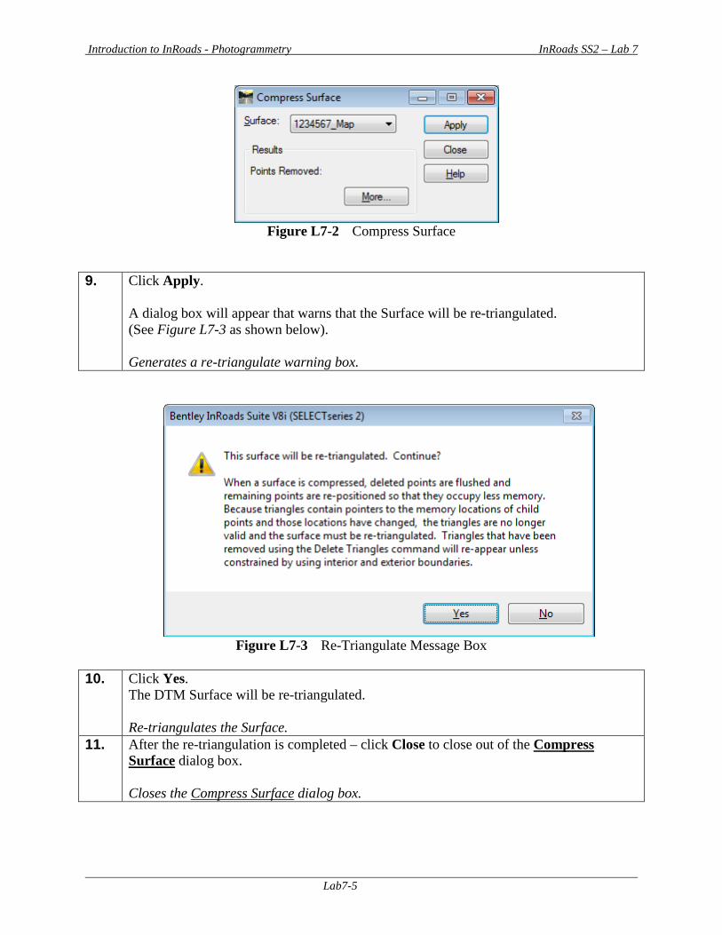
Introduction to InRoads - Photogrammetry InRoads SS2 – Lab 7
Lab7-5
Figure L7-2 Compress Surface
9. Click Apply.
A dialog box will appear that warns that the Surface will be re-triangulated. (See Figure L7-3 as shown below). Generates a re-triangulate warning box.
Figure L7-3 Re-Triangulate Message Box
10. Click Yes.
The DTM Surface will be re-triangulated. Re-triangulates the Surface.
11. After the re-triangulation is completed – click Close to close out of the Compress Surface dialog box. Closes the Compress Surface dialog box.

Introduction to InRoads - Photogrammetry InRoads SS2 – Lab 7
Lab7-6
12. Save the InRoads Surface File After re-triangulating and compressing the DTM Surface – the data will need to be saved. As mentioned previously, InRoads retains the data in temporary memory but does not save the data on the fly. Whenever a change has been made to an InRoads Surface Project – Save the project and its associated modifications or changes. Select FileSave Surface from the InRoads Menu. Please Note: (The “Save As” dialog box may not appear because the Surface has already been saved initially). The Surface Project (1234567_Map.dtm) will be saved to Lab 7 in the following path: C:\InRoads Data\1234567\Photogrammetry Labs\Lab7 Note that the InRoads and MicroStation Status Bar (Located at the bottom of both the InRoads and MicroStation Interface) will depict a message when the Surface Project has been saved. The 1234567_Map Surface Project has now been saved to the following path: C:\InRoads Data\1234567\Photogrammetry Labs\Lab7
13. The 1234567_Map.dtm Surface Project is now ready for submittal to the District. This file will be sent to the District SDE as a completed Surface Project. This .DTM file replaces the CAiCE .SRV file format. The DTM file contains all of the Features (random points, breaklines, borders, obscured features, etc.) that used to be contained in the CAICE .SRV File. The DTM Surface is already triangulated for the SDE so that he can begin adding the field enhancements. The 1234567_Map.dtm file is processed and submitted to the District.
Introduction to InRoads - Photogrammetry InRoads SS2 – Lab 7
Lab7-7
Lab7B Generate the Deliverables The DTM Surface has been processed (1234567_Map.dtm) and the Topo DGN file (1234567_Map.dgn) has been created from Softcopy. The Office of Design Policy and Support/Location Bureau will submit the following information to the Districts either by delivery of a CD or submittal on a Network Share:
The Final Deliverables include the following:
• A processed DTM Surface file (1234567_Map.dtm) • A topographical DGN file (1234567_Map.dgn) • DGN Plot Files (1234567_Map1.pdf, 1234567_Map2.pdf, etc.) • Mapping Photographs • A Roll Plot of the topographical DGN data (if required) • A Photogrammetry Quality Assurance Checklist Document
End This concludes the Tutorials and the Labs.

Notes