introduction to optical burst switching - tlm.unavarra.es fileÁrea de ingeniería telemática...
TRANSCRIPT
Área de Ingeniería Telemática
Introduction toOptical Burst Switching
Area de Ingeniería Telemáticahttp://www.tlm.unavarra.es
Área de Ingeniería Telemática
LANs

2/41
Áre
a de
Inge
nier
ía T
elem
átic
aCampus-wide LAN
Acceso
Distribución
CoreServidores
Laye
r 2
Área de Ingeniería Telemática
WANs

4/41
Áre
a de
Inge
nier
ía T
elem
átic
aWANs

5/41
Áre
a de
Inge
nier
ía T
elem
átic
aWANs

6/41
Áre
a de
Inge
nier
ía T
elem
átic
aWANs

7/41
Áre
a de
Inge
nier
ía T
elem
átic
aWANs

8/41
Áre
a de
Inge
nier
ía T
elem
átic
aWANs
9/41
Áre
a de
Inge
nier
ía T
elem
átic
aWANs
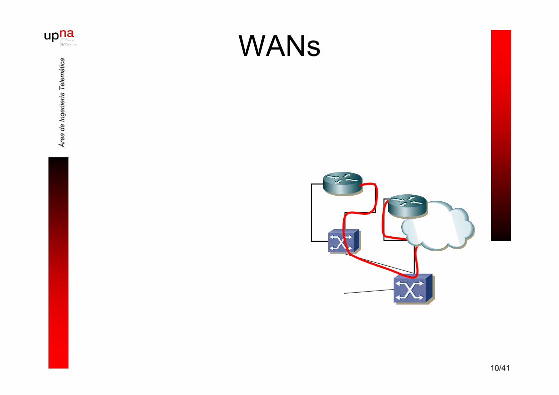
10/41
Áre
a de
Inge
nier
ía T
elem
átic
aWANs

11/41
Áre
a de
Inge
nier
ía T
elem
átic
aWANs

12/41
Áre
a de
Inge
nier
ía T
elem
átic
aWANs
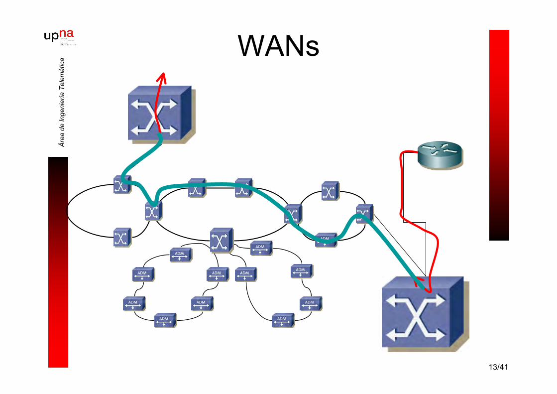
13/41
Áre
a de
Inge
nier
ía T
elem
átic
aWANs

14/41
Áre
a de
Inge
nier
ía T
elem
átic
aWANs

15/41
Áre
a de
Inge
nier
ía T
elem
átic
a… back to square one

16/41
Áre
a de
Inge
nier
ía T
elem
átic
a… back to square one
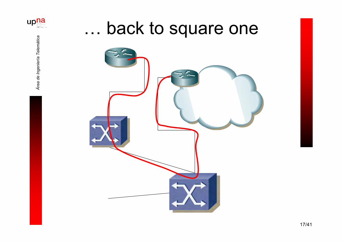
17/41
Áre
a de
Inge
nier
ía T
elem
átic
a… back to square one

18/41
Áre
a de
Inge
nier
ía T
elem
átic
a… back to square one
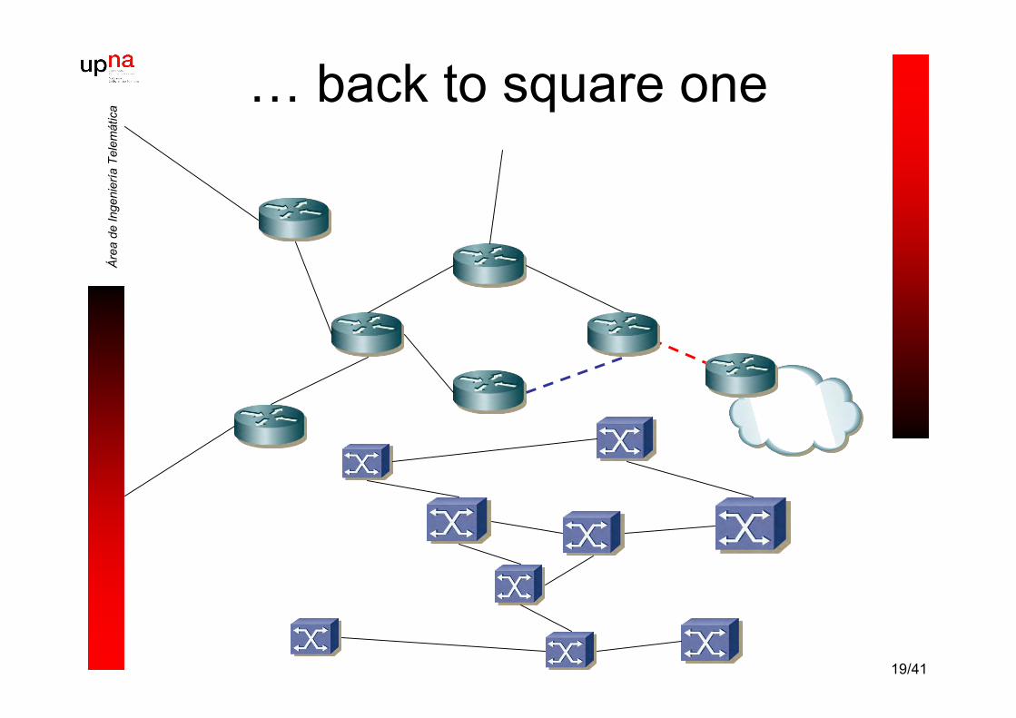
19/41
Áre
a de
Inge
nier
ía T
elem
átic
a… back to square one
20/41
Áre
a de
Inge
nier
ía T
elem
átic
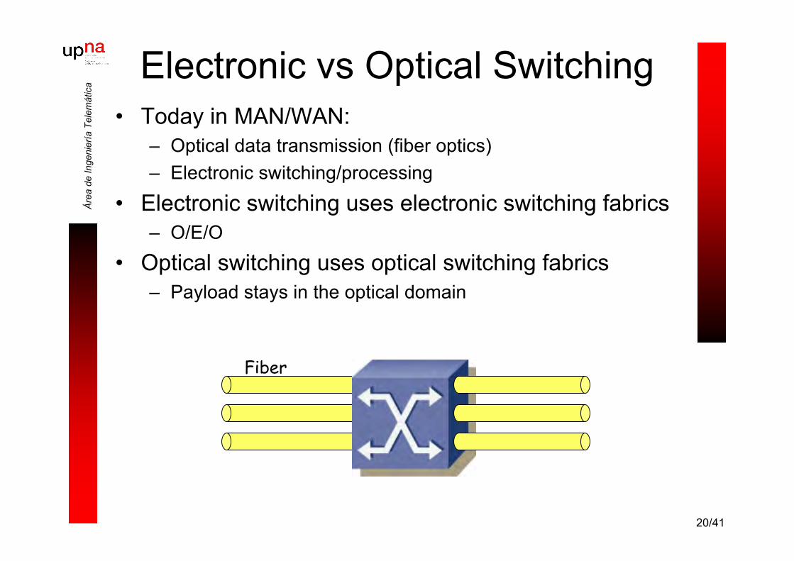
aElectronic vs Optical Switching
• Today in MAN/WAN:– Optical data transmission (fiber optics)– Electronic switching/processing
• Electronic switching uses electronic switching fabrics– O/E/O
• Optical switching uses optical switching fabrics– Payload stays in the optical domain
Fiber
21/41
Áre
a de
Inge
nier
ía T
elem
átic
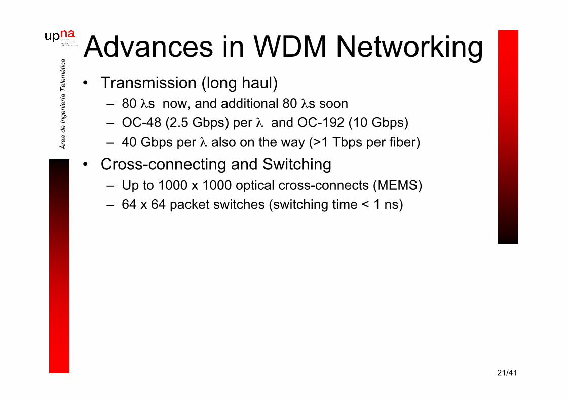
aAdvances in WDM Networking• Transmission (long haul)
– 80 λs now, and additional 80 λs soon– OC-48 (2.5 Gbps) per λ and OC-192 (10 Gbps)– 40 Gbps per λ also on the way (>1 Tbps per fiber)
• Cross-connecting and Switching– Up to 1000 x 1000 optical cross-connects (MEMS)– 64 x 64 packet switches (switching time < 1 ns)
22/41
Áre
a de
Inge
nier
ía T
elem
átic
aCaveats of OEO Switching
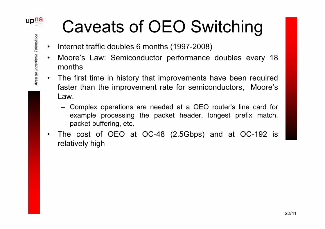
• Internet traffic doubles 6 months (1997-2008)• Moore’s Law: Semiconductor performance doubles every 18
months• The first time in history that improvements have been required
faster than the improvement rate for semiconductors, Moore’sLaw.– Complex operations are needed at a OEO router's line card for
example processing the packet header, longest prefix match,packet buffering, etc.
• The cost of OEO at OC-48 (2.5Gbps) and at OC-192 isrelatively high

23/41
Áre
a de
Inge
nier
ía T
elem
átic
aCircuit Switching
• Two-way (request and acknowledge)• RTT = tens of ms• Long setup delays• Suitable for smooth traffic and QoS
guarantees due to fixed bandwidthallocation
• Inefficient for bursty (data) traffic– Wasted bandwidth during off/low-traffic
periods– Overhead due to frequent set-up/release
Connect
Optical path
time
Tsetup
ACK

24/41
Áre
a de
Inge
nier
ía T
elem
átic
a Wavelength Routing
• Lightpath (or λ path) is like a circuit• λ-path specific pros and cons:
– Very coarse granularity (OC-48 and above)– Limited # of wavelengths (thus # of lightpaths)– No aggregation (merge of λs) inside the core
• traffic grooming at the edge can be complex/inflexible– Mature OXC technology (msec switching time)
• Current state of the art

25/41
Áre
a de
Inge
nier
ía T
elem
átic
aPacket Switching
• A packet contains a header (e.g., addresses) and thepayload (variable or fixed length)– Can be sent without circuit set-up delay– Statistic sharing of link bandwidth among packets with
different source/destination
• Store-and-forward at each node– Buffers a packet, processes its header, and sends it to the
next hop
• One-way process

26/41
Áre
a de
Inge
nier
ía T
elem
átic
aOptical Packet Switching
• Optical packet consists of a header and a payload• Packet header is processed all-optically at each node
and switched to the next hop
+ Statistical multiplexing of data+ Suitable for bursty traffic
- Requires fast switching speeds (nanoseconds)- Stringent synchronization requirements- Lack of optical memory- More viewed as a longer term solution

27/41
Áre
a de
Inge
nier
ía T
elem
átic
aOBS Approach
• Main design objectives– Decreasing complexity of OPS– Statistical multiplexing in optical domain– Buffer-less network– User data travels transparently as an optical signal and cuts
through the switches at very high rates
• Solution– Sending a header to temporarily reserve a wavelength path– After that, sending an optical burst (a block of IP packets)
through the network
• Thanks to the great variability in the duration ofbursts, the OBS can be viewed as lying betweenOPS (one-way reservation) and WS networks (two-way reservation)

28/41
Áre
a de
Inge
nier
ía T
elem
átic
a
Nodo troncal (OXC)Nodo frontera
FEC1
FECn
Varias fibrasVarias λs por fibra
OBS: Tipos de nodosFrontera (edge)• Agrupan paquetes en ráfagas• Envían las ráfagas a la red• Desensamblan ráfagas
Troncal (core)• Procesan la señalización• Conmutan las ráfagas en el
dominio óptico• Resuelven la contienda

29/41
Áre
a de
Inge
nier
ía T
elem
átic
aOBS: Señalización
BCP
Ráfa
ga
TOXC
Camino óptico deorigen a destino
• Se envía con anterioridad a laráfaga
• Por un canal diferente• Se procesa electrónicamente• Separación temporal suficiente
para crear un caminoconmutado
• Sin confirmación (TAG):– Ráfaga de 100KB a 10Gbps: 80
µs de transmisión– 200Km: 1ms de propagación
• Tell-and-Wait (TAW)
tiempo
Tsetup
30/41
Áre
a de
Inge
nier
ía T
elem
átic
a
BCP
Ráfa
ga
TOXC
IBT
Reservatiempo
BCP BCP
Reserva
TOXC
TOXC
Tsetup
Ráfa
ga Reserva Ráfa
ga
Tsetup Tsetup
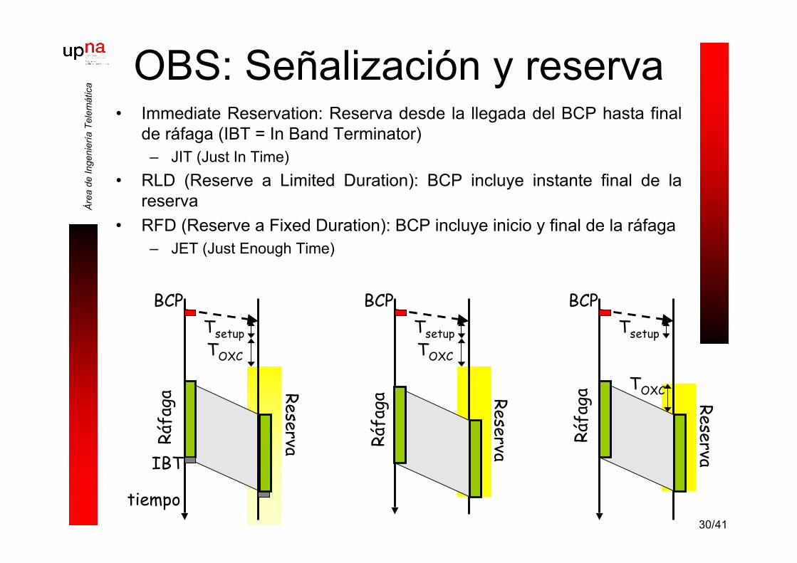
OBS: Señalización y reserva• Immediate Reservation: Reserva desde la llegada del BCP hasta final
de ráfaga (IBT = In Band Terminator)– JIT (Just In Time)
• RLD (Reserve a Limited Duration): BCP incluye instante final de lareserva
• RFD (Reserve a Fixed Duration): BCP incluye inicio y final de la ráfaga– JET (Just Enough Time)

31/41
Áre
a de
Inge
nier
ía T
elem
átic
aOBS: Conmutador
• Switch Control Unit• Optical Cross Connect
OXC
SCU
• Canales de control• Canales de datos
32/41
Áre
a de
Inge
nier
ía T
elem
átic
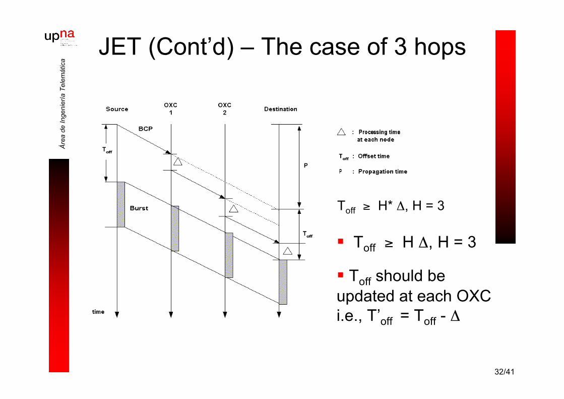
aJET (Cont’d) – The case of 3 hops
Toff ≥ H Δ, H = 3
Toff should beupdated at each OXCi.e., T’off = Toff - Δ
Toff ≥ H* Δ, H = 3

33/41
Áre
a de
Inge
nier
ía T
elem
átic
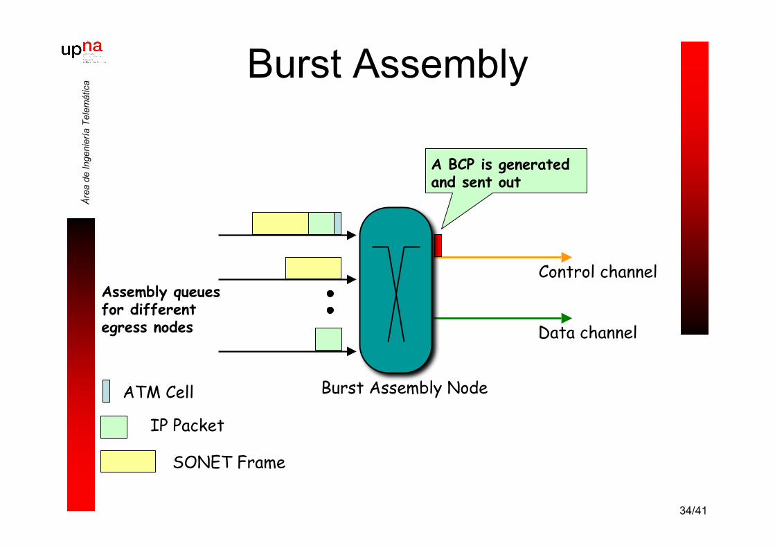
aBurst Assembly
Burst Assembly Node
Assembly queuesfor differentegress nodes Data channel
Control channel
ATM Cell
SONET Frame
IP Packet
Time or lengththreshold is reached
34/41
Áre
a de
Inge
nier
ía T
elem
átic
aBurst Assembly
A BCP is generatedand sent out
Burst Assembly Node
Assembly queuesfor differentegress nodes Data channel
Control channel
ATM Cell
SONET Frame
IP Packet

35/41
Áre
a de
Inge
nier
ía T
elem
átic
aBurst Assembly
Burst Assembly Node
Assembly queuesfor differentegress nodes Data channel
Control channel
ATM Cell
SONET Frame
IP Packet
36/41
Áre
a de
Inge
nier
ía T
elem
átic
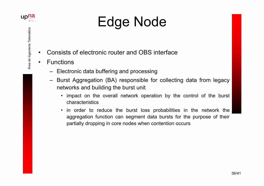
aEdge Node
• Consists of electronic router and OBS interface• Functions
– Electronic data buffering and processing– Burst Aggregation (BA) responsible for collecting data from legacy
networks and building the burst unit• impact on the overall network operation by the control of the burst
characteristics• in order to reduce the burst loss probabilities in the network the
aggregation function can segment data bursts for the purpose of theirpartially dropping in core nodes when contention occurs

37/41
Áre
a de
Inge
nier
ía T
elem
átic
aEdge Node
– Setting up the pre-transmission offset time• in simple fixed offset scheme, the offset time is
calculated as a sum of the total processing times at allthe intermediate hops
• offset time is one of the crucial OBS network parameterssince its incorrect estimation has impact on data lost
– Sending the control packet– Sending the burst
38/41
Áre
a de
Inge
nier
ía T
elem
átic
a
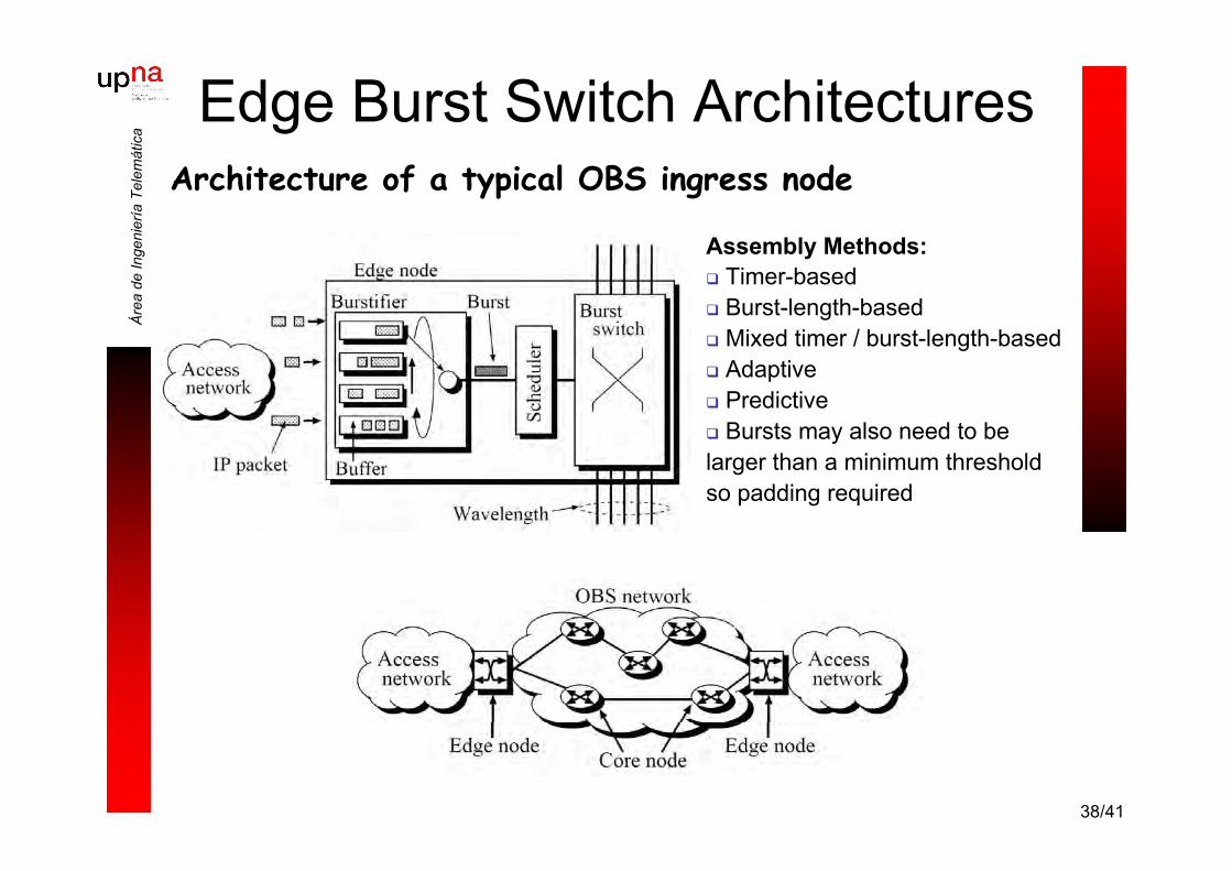
Architecture of a typical OBS ingress node
Assembly Methods: Timer-based Burst-length-based Mixed timer / burst-length-based Adaptive Predictive Bursts may also need to belarger than a minimum thresholdso padding required
Edge Burst Switch Architectures

39/41
Áre
a de
Inge
nier
ía T
elem
átic
a
• Hardware requirements– O/E/O conversion for header processing– λ-conversion– Switching speeds fast enough– M ports, c wavelengths per port; Mc x Mc switch– Eventually optical “buffering” (FDLs)
• Por construcción las FDLs normalmente presentan un retardo múltiplode un valor básico “D”
• Operation– Processing of incoming control packets (electronically) and sending
it to the next node that lays on the routing path– Contention resolution (by a proper scheduling algorithm)
Core Node
20D 21D 2nDConmutadoressensibles a λ
40/41
Áre
a de
Inge
nier
ía T
elem
átic
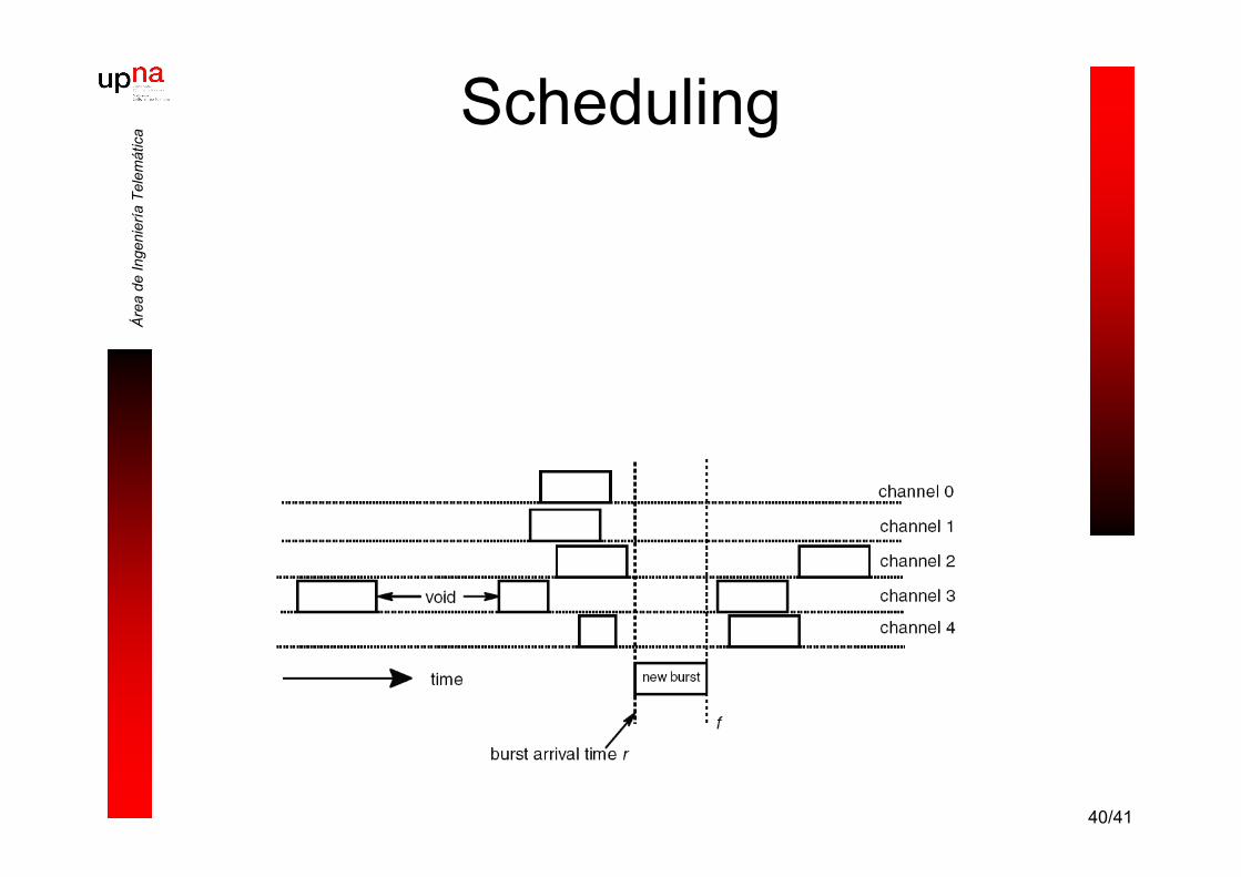
aScheduling

41/41
Áre
a de
Inge
nier
ía T
elem
átic
aLecturas
• T. Battestilli and H. Perros. An introduction to optical burst switching.IEEE Communications Magazine, 41(8):S10–S15, August 2003.
• C. Qiao and M. Yoo. Optical burst switching (obs) - a new paradigm foran optical internet. Journal of High-Speed Networks, 8(1), 1999.
• Y. Chen, C. Qiao, and X. Yu. Optical burst switching: A new area inoptical networking research. IEEE Network, 18(3):16–23, May/June2004.
• S. Verma, H. Chaska, and R. Ravikanth. Optical burst switching: aviable solution for terabit ip backbone. IEEE Network, 14(6):48–53,Nov./Dec. 2000.