intrusion-tolerant replication under …yairamir/jonkirsch_thesis.pdfin fall 2008, i had the...
TRANSCRIPT
INTRUSION-TOLERANT REPLICATION UNDER ATTACK
by
Jonathan Kirsch
A dissertation submitted to The Johns Hopkins University inconformity with the requirements for
the degree of Doctor of Philosophy.
Baltimore, Maryland
February, 2010
c© Jonathan Kirsch 2010
All rights reserved
Abstract
Much of our critical infrastructure is controlled by large software systems whose participants
are distributed across the Internet. As our dependence on these critical systems continues to grow,
it becomes increasingly important that they meet strict availability and performance requirements,
even in the face of malicious attacks, including those that are successful in compromising parts of the
system. This dissertation presents the first replication protocols capable of guaranteeing correctness,
availability, and good performance even when some of the servers are compromised, enabling the
construction of highly available and highly resilient systems for our critical infrastructure.
Prior to this work, intrusion-tolerant replication protocols were designed to perform well in
fault-free executions, and this is how they were evaluated.In this dissertation we point out that many
state-of-the-art protocols are vulnerable to significant performance degradation by a small number
of malicious processors. We define a new performance-oriented correctness criterion,BOUNDED-
DELAY , against which intrusion-tolerant replication protocolscan be evaluated. Protocols that meet
BOUNDED-DELAY are required to provide a consistent level of performance, even when the system
is under attack by an adversary that controls some of the processors.
We present Prime, an intrusion-tolerant replication protocol that meetsBOUNDED-DELAY and
thus offers a stronger performance guarantee under attack than previous state-of-the-art protocols.
An evaluation of a prototype implementation shows that Prime performs competitively with existing
ii
protocols in fault-free executions and achieves an order ofmagnitude performance improvement in
under-attack executions in 4-server and 7-server configurations.
Using Prime as a building block, we show how to design and implement an attack-resilient,
large-scale intrusion-tolerant replication system for wide-area networks. The system is hierarchical
and is suited to deployments consisting of several wide-area sites, each with a cluster of replication
servers. We present three mechanisms for attack-resilientand efficient inter-site communication,
which enable the system to perform well in bandwidth-constrained wide-area networks without
making it susceptible to performance degradation caused bymalicious servers. Our results provide
evidence that it is possible to construct highly resilient,large-scale survivable systems that perform
well even when some of the servers (and some entire sites) arecompromised.
Advisor: Yair Amir
Readers: Randal BurnsBrian Coan
iii
Acknowledgements
I am deeply indebted to my advisor, Yair Amir, for taking a chance on me in spite of the obstacles
we would have to overcome together. Yair fostered an environment of openness and collaboration
that helped make the lab such a special place to work. I thank him for opening many doors for me
during my time at Johns Hopkins and for teaching me the importance of the big picture. I will carry
his lessons with me as I move to the next phase of my career.
I am profoundly grateful to two amazing colleagues, researchers, and friends, John Lane and
Brian Coan, with whom I collaborated on all aspects of this dissertation. I thank John for being a
role model to me from the very beginning and for his wisdom andpatience. His ability to know
something about everything continues to inspire me to learnas much as I can each day. Brian Coan,
my mentor during my two summers at Telcordia Technologies, is the type of researcher I hope to
become. His feedback over the years, especially his attention to detail and his urge to simplify
and clarify, has improved my work immeasurably. I also thankhim for serving on my GBO and
dissertation committees.
I am thankful to the many other people with whom I collaborated over the last five and a half
years. I thank Claudiu Danilov for teaching me a great deal during my first years at Hopkins. The
warmth and enthusiasm he exuded during my initial visit to the lab immediately put me at ease and
made me know I would feel comfortable here. I also thank DannyDolev, whose dedication and help
iv

during his visit to the lab in 2005 made the Steward system possible. Danny’s level of patience and
persistence is something I strive to emulate. Thanks also toCristina Nita-Rotaru, for her support
and advice over the years; John Schultz, for the countless hours he spent working with me on fault-
tolerant replication systems; Josh Olsen and David Zage, for their help making Steward a reality;
and Marina Blanton, for collaborating with me on the secret handshakes work.
I wish to thank a number of faculty members at Johns Hopkins for their help and support. Thanks
to Randal Burns, for serving on my GBO and dissertation committees and for his help during the
Transaction Processing Systems course; Giuseppe Ateniese, for collaborating with me on one of my
qualifying projects and for serving on my GBO committee; Andreas Terzis, whose kindness helped
convince me to come to Hopkins; and Robert Rynasiewicz, for chairing my GBO committee.
I am grateful for the support of a number friends associated with the Distributed Systems and
Networks lab. I thank Raluca Musaloiu-Elefteri for helping me keep a positive perspective on
things, for keeping the lab running smoothly, and for her support in the days leading up to our
defenses. Thanks to Nilo Rivera for always being willing to listen to me ramble about Byzantine
fault tolerance and for offering his insight. I thank Michael Kaplan for his friendship during the first
two years, for working with me in the Distributed Systems andSecurity and Privacy courses, and
for making sure we took the time to have some fun once in a while. I also wish to thank Ciprian
Tutu, Jacob Green, Jonathan Stanton, Michal Miskin-Amir, and the other great people with whom I
have interacted over the years.
In Fall 2008, I had the privilege to spend a month working withthe Navigators Distributed
Systems Research Team at the University of Lisboa, Portugal. I wish to thank Paulo Verıssimo,
Miguel Correia, Alysson Bessani, Paulo Sousa, Antonio Casimiro, Henrique Moniz, Giuliana San-
tos Veronese, Monica Dixit, and Wagner Dantas for making myfirst trip to Europe an enjoyable
one.
v

Over the last five years, I had the pleasure to be part of Ketzev, the Jewish a cappella group
at Johns Hopkins. I am grateful to the members of Ketzev for allowing me to pursue my passion
for singing even as a graduate student and for helping me to escape the pressures of exams and
paper writing. I cherish the many friendships I have made. I also want to thank the students of the
Distributed Systems, Advanced Distributed Systems, and Intermediate Programming courses for
making our interactions so enjoyable.
I am indebted to Arvind Krishnamurthy and Michael J. Fischer, two of my professors at Yale,
for encouraging me to pursue graduate study and for agreeingto work with me as I was learning
what computer science was all about.
I will forever be grateful to my girlfriend and best friend, Kari Sepelyak. I can’t imagine having
gone through this process without her. I am so fortunate to have found someone who truly under-
stands me. Her sensitivity and love have made each day since I’ve known her more special than the
last. I thank her for being such a good one. I also want to thankKari’s parents, Nancy and Bob, and
her brothers, Chris and Jaime, for making me feel so at home during my many visits to Delaware.
Last but not least, I want to thank my parents, Robert and Barbara, and my siblings, Jamie,
Jennifer, and Matthew, for their endless and unconditionalsupport over the years. I would be lost
without their guidance and love.
During my time at Hopkins I received support from the DefenseAdvanced Research Projects
Agency (contract FA8750-04-2-0232) and the National Science Foundation (grants 0430271 and
0716620).
vi
Contents
Abstract ii
Acknowledgements iv
List of Tables xii
List of Figures xiii
List of Algorithms xv
1 Introduction 1
1.1 Contributions of the Dissertation . . . . . . . . . . . . . . . . . .. . . . . . . . . 3
1.1.1 A New Way of Thinking about Intrusion-Tolerant Replication . . . . . . . 4
1.1.2 Prime: Intrusion-Tolerant Replication Under Attack. . . . . . . . . . . . 7
1.1.3 An Attack-Resilient Architecture for Large-Scale Intrusion-Tolerant Repli-
cation . . . . . . . . . . . . . . . . . . . . . . . . . . . . . . . . . . . . . 9
1.2 Dissertation Organization . . . . . . . . . . . . . . . . . . . . . . . .. . . . . . . 11
1.3 Related Work . . . . . . . . . . . . . . . . . . . . . . . . . . . . . . . . . . . . .12
1.3.1 Benign Fault-Tolerant State Machine Replication . . .. . . . . . . . . . . 13
1.3.2 Intrusion-Tolerant State Machine Replication . . . . .. . . . . . . . . . . 14
vii
1.3.3 Intrusion-Tolerant Group Communication . . . . . . . . . .. . . . . . . . 18
1.3.4 Intrusion-Tolerant Replication for Wide-Area Networks . . . . . . . . . . 19
1.3.5 State Machine-Based Logical Machines . . . . . . . . . . . . .. . . . . . 21
1.3.6 Attack-Resilient Intrusion-Tolerant Replication .. . . . . . . . . . . . . . 22
1.3.7 Intrusion Tolerance in a Hybrid Failure Model . . . . . . .. . . . . . . . 24
2 Background 27
2.1 Threshold Digital Signatures . . . . . . . . . . . . . . . . . . . . . .. . . . . . . 27
2.2 Erasure-Resilient Coding . . . . . . . . . . . . . . . . . . . . . . . . .. . . . . . 29
2.3 Intrusion-Tolerant Reliable Broadcast . . . . . . . . . . . . .. . . . . . . . . . . 29
3 Performance Under Attack: A Case Study 32
3.1 BFT Overview . . . . . . . . . . . . . . . . . . . . . . . . . . . . . . . . . . . . 33
3.2 Attack 1: Pre-Prepare Delay . . . . . . . . . . . . . . . . . . . . . . . .. . . . . 34
3.3 Attack 2: Timeout Manipulation . . . . . . . . . . . . . . . . . . . . .. . . . . . 36
4 The Prime Replication Protocol 37
4.1 System Model and Service Properties . . . . . . . . . . . . . . . . .. . . . . . . 39
4.1.1 Safety Properties . . . . . . . . . . . . . . . . . . . . . . . . . . . . . .. 40
4.1.2 Liveness and Performance Properties . . . . . . . . . . . . . .. . . . . . 41
4.1.3 Practical Considerations . . . . . . . . . . . . . . . . . . . . . . .. . . . 44
4.2 Prime: Design and Overview . . . . . . . . . . . . . . . . . . . . . . . . .. . . . 46
4.2.1 Separating Dissemination from Ordering . . . . . . . . . . .. . . . . . . 46
4.2.2 Ordering Strategies . . . . . . . . . . . . . . . . . . . . . . . . . . . .. . 47
4.2.3 Mapping Strategies to Sub-Protocols . . . . . . . . . . . . . .. . . . . . . 50
4.3 Prime: Technical Details . . . . . . . . . . . . . . . . . . . . . . . . . .. . . . . 52
viii
4.3.1 The Client Sub-Protocol . . . . . . . . . . . . . . . . . . . . . . . . .. . 52
4.3.2 The Preordering Sub-Protocol . . . . . . . . . . . . . . . . . . . .. . . . 54
4.3.3 The Global Ordering Sub-Protocol . . . . . . . . . . . . . . . . .. . . . . 57
4.3.4 The Reconciliation Sub-Protocol . . . . . . . . . . . . . . . . .. . . . . . 60
4.3.5 The Suspect-Leader Sub-Protocol . . . . . . . . . . . . . . . . .. . . . . 64
Mechanism 1: Reporting the LatestPO-SUMMARY Messages . . . . . . . . 65
Mechanism 2: Measuring the Turnaround Time . . . . . . . . . . . . . .. 66
Mechanism 3: The Distributed Monitoring Protocol . . . . . . . .. . . . . 68
Correctness Proofs . . . . . . . . . . . . . . . . . . . . . . . . . . . . . . 73
4.3.6 The Leader Election Sub-Protocol . . . . . . . . . . . . . . . . .. . . . . 75
4.4 The Prime View Change Protocol . . . . . . . . . . . . . . . . . . . . . .. . . . 77
4.4.1 Background: BFT’s View Change Protocol . . . . . . . . . . . .. . . . . 77
4.4.2 Motivation and Protocol Overview . . . . . . . . . . . . . . . . .. . . . . 78
4.4.3 Detailed Protocol Description . . . . . . . . . . . . . . . . . . .. . . . . 80
4.5 Proof Sketch of Bounded-Delay . . . . . . . . . . . . . . . . . . . . . .. . . . . 84
4.6 Performance Evaluation . . . . . . . . . . . . . . . . . . . . . . . . . . .. . . . . 85
4.7 Prime Summary . . . . . . . . . . . . . . . . . . . . . . . . . . . . . . . . . . . .93
5 An Attack-Resilient Architecture for Large-Scale Intrusion-Tolerant Replication 94
5.1 System Model . . . . . . . . . . . . . . . . . . . . . . . . . . . . . . . . . . . . .97
5.2 Background: A Customizable Replication Architecture .. . . . . . . . . . . . . . 100
5.3 Building an Attack-Resilient Architecture . . . . . . . . . .. . . . . . . . . . . . 101
5.3.1 Making Each Piece Attack Resilient . . . . . . . . . . . . . . . .. . . . . 102
5.3.2 Design Dependencies Among the Pieces . . . . . . . . . . . . . .. . . . . 103
5.3.3 Choosing the State Machine Replication Protocols . . .. . . . . . . . . . 104
ix
5.4 Attack-Resilient Logical Links . . . . . . . . . . . . . . . . . . . .. . . . . . . . 106
5.4.1 Erasure Encoding-Based Logical Link . . . . . . . . . . . . . .. . . . . . 108
Blacklisting Servers that Send Invalid Parts . . . . . . . . . . . .. . . . . 111
5.4.2 Hub-Based Logical Link . . . . . . . . . . . . . . . . . . . . . . . . . .. 116
5.4.3 Dependable Forwarder-Based Logical Link . . . . . . . . . .. . . . . . . 119
5.4.4 Discussion . . . . . . . . . . . . . . . . . . . . . . . . . . . . . . . . . . 123
5.5 Putting It All Together . . . . . . . . . . . . . . . . . . . . . . . . . . . .. . . . 125
5.5.1 Handling Non-Determinism in the Global Instance of Prime . . . . . . . . 129
5.6 Service Properties . . . . . . . . . . . . . . . . . . . . . . . . . . . . . . .. . . . 130
5.6.1 Safety Properties . . . . . . . . . . . . . . . . . . . . . . . . . . . . . .. 130
5.6.2 Liveness and Performance Properties . . . . . . . . . . . . . .. . . . . . 131
Achieving Bounded Logical Machine Processing Time . . . . . . .. . . . 133
Supporting Prime’s Virtual Traffic Classes . . . . . . . . . . . . . .. . . . 135
5.7 Performance Evaluation . . . . . . . . . . . . . . . . . . . . . . . . . . .. . . . . 139
5.7.1 Testbed and Network Setup . . . . . . . . . . . . . . . . . . . . . . . .. 140
5.7.2 Test Configurations . . . . . . . . . . . . . . . . . . . . . . . . . . . . .. 141
5.7.3 Evaluation . . . . . . . . . . . . . . . . . . . . . . . . . . . . . . . . . . 142
5.8 Attack-Resilient Architecture Summary . . . . . . . . . . . . .. . . . . . . . . . 146
6 Conclusions 148
Bibliography 150
A Design of an Attack on a Decentralized Intrusion-TolerantReplication Protocol 161
A.1 RITAS Overview . . . . . . . . . . . . . . . . . . . . . . . . . . . . . . . . . . .162
A.2 Designing an Adversary . . . . . . . . . . . . . . . . . . . . . . . . . . . .. . . 165
x
A.3 A Building Block: The Stagger Attack . . . . . . . . . . . . . . . . .. . . . . . . 166
A.4 Attack Part 1: Causing Divergence of MVC Inputs . . . . . . . .. . . . . . . . . 167
A.5 Attack Part 2: Pushing Multi-Valued Consensus Towards⊥ . . . . . . . . . . . . . 172
Vita 174
xi
List of Tables
4.1 Traffic class of each Prime message type. . . . . . . . . . . . . . .. . . . . . . . 534.2 Summary of Prime’s view change protocol. . . . . . . . . . . . . .. . . . . . . . 81
5.1 Summary of Logical Link Protocols. . . . . . . . . . . . . . . . . . .. . . . . . . 123
A.1 The Stagger Attack on Bracha’s Reliable Broadcast protocol. . . . . . . . . . . . . 167
xii
List of Figures
3.1 Common-case operation of the BFT algorithm whenf = 1. . . . . . . . . . . . . 33
4.1 Terminology used by the Preordering sub-protocol. . . . .. . . . . . . . . . . . . 564.2 Fault-free operation of Prime (f = 1). . . . . . . . . . . . . . . . . . . . . . . . . 604.3 Operation of Prime with a malicious leader that performswell enough to avoid being
replaced (f = 1). . . . . . . . . . . . . . . . . . . . . . . . . . . . . . . . . . . . 664.4 Throughput of Prime and BFT as a function of the number of clients in a 7-server
configuration. Servers were connected by 50 ms, 10 Mbps links. . . . . . . . . . . 884.5 Latency of Prime and BFT as a function of the number of clients in a 7-server
configuration. Servers were connected by 50 ms, 10 Mbps links. . . . . . . . . . . 884.6 Throughput of Prime and BFT as a function of the number of clients in a 4-server
configuration. Servers were connected by 50 ms, 10 Mbps links. . . . . . . . . . . 894.7 Latency of Prime and BFT as a function of the number of clients in a 4-server
configuration. Servers were connected by 50 ms, 10 Mbps links. . . . . . . . . . . 894.8 Throughput of Prime as a function of the number of clientsin a 7-server, local-area
network configuration. . . . . . . . . . . . . . . . . . . . . . . . . . . . . . . .. 904.9 Latency of Prime as a function of the number of clients in a7-server, local-area
network configuration. . . . . . . . . . . . . . . . . . . . . . . . . . . . . . . .. 904.10 Throughput of BFT in under-attack executions as a function of the number of clients
in a 7-server, local-area network configuration. . . . . . . . . .. . . . . . . . . . 924.11 Latency of BFT in under-attack executions as a functionof the number of clients in
a 7-server, local-area network configuration. . . . . . . . . . . .. . . . . . . . . . 92
5.1 An example erasure encoding-based logical link, withf = 1. . . . . . . . . . . . 1095.2 Intuition behind the correctness of the erasure encoding-based logical link. In this
example,f = 2. The adversary can block at mostf virtual links by corruptingservers in the sending site andf virtual links by corrupting servers in the receivingsite. . . . . . . . . . . . . . . . . . . . . . . . . . . . . . . . . . . . . . . . . . . 110
5.3 Network configuration of the hub-based logical link. . . .. . . . . . . . . . . . . 1165.4 Internal organization of a server in the attack-resilient architecture when the de-
pendable forwarder-based logical link is deployed. . . . . . .. . . . . . . . . . . 1265.5 Internal organization of a server in the attack-resilient architecture when the erasure
encoding- or hub-based logical link is deployed. . . . . . . . . .. . . . . . . . . . 128
xiii

5.6 Throughput of the attack-resilient architecture as a function of the number of clientsin a 7-site configuration. Each site had 7 servers. Sites wereconnected by 50 ms,10 Mbps links. . . . . . . . . . . . . . . . . . . . . . . . . . . . . . . . . . . . . 144
5.7 Latency of the attack-resilient architecture as a function of the number of clientsin a 7-site configuration. Each site had 7 servers. Sites wereconnected by 50 ms,10 Mbps links. . . . . . . . . . . . . . . . . . . . . . . . . . . . . . . . . . . . . 144
5.8 Isolating the throughput obtained when using the hub-based logical links. . . . . . 1455.9 Isolating the latency obtained when using the hub-basedlogical links. . . . . . . . 145
A.1 The RITAS protocol stack. . . . . . . . . . . . . . . . . . . . . . . . . . .. . . . 162
xiv
List of Algorithms
1 Bracha’s Asynchronous Reliable Broadcast Protocol . . . . .. . . . . . . . . . . 31
2 Prime Reconciliation Procedure . . . . . . . . . . . . . . . . . . . . . .. . . . . 61
3 Suspect-Leader Distributed Monitoring Protocol . . . . . . .. . . . . . . . . . . . 72
4 Blacklisting Protocol for the Attack-Resilient Architecture . . . . . . . . . . . . . 115
5 Attacking the RITAS Atomic Broadcast Protocol . . . . . . . . . .. . . . . . . . 169
xv
Chapter 1
Introduction
Much of our critical infrastructure is controlled by large software systems whose participants
are distributed across the Internet. These systems supporta diverse set of important applications,
ranging from tools for e-commerce to the Supervisory Control and Data Acquisition (SCADA)
systems that control the power grid. As our dependence on these systems continues to grow, it
becomes increasingly important that they meet strict availability and performance requirements,
even in the face of malicious attacks, including those that are successful in compromising parts of
the system. This dissertation is about how to design and implement large-scale, survivable systems
that guarantee correctness, availability, and good performance even when some of the machines are
compromised.
The most common approach taken today to securing our critical systems is to build asecurity
fortressaround them, protecting them with layers of defenses built from well-known and widely
used security technologies, such as firewalls and access control mechanisms. The machines inside
the security fortress are assumed (and trusted) to be correct, and the goal is to protect the machines
on the inside from attackers on the outside. While critical systems may have operated exclusively on
private networks in the past, thus affording them some degree of protection from external attackers,
1
many of them are now connected to the Internet (e.g., [8, 75])and are vulnerable to a range of
threats that may not have been considered when the systems were originally designed. Given that
thousands of machines are compromised on the Internet each day [3], it seems likely that some of the
attacks will be able to breach the fortress walls of even those critical systems specifically designed
with security in mind. In addition, insider attacks, such asfrom disgruntled employees who take
advantage of existing security vulnerabilities, are becoming more and more common [48, 66] and
are a growing source of machine compromise. Such attacks do not need to breach the fortress walls
at all: the attacker already has the credentials to access the system, and the power to abuse them.
In order to bring the fault tolerance capabilities of critical systems in line with our requirements,
a great deal of research has been done on building systems that areintrusion-tolerant[80]. Intrusion-
tolerant systems can continue functioning even if part of the system is compromised. The design
of intrusion-tolerant systems is motivated by the assumption that it is not possible to enumerate all
of the potential attacks on a system that can be mounted by compromised machines. Therefore,
the system should be designed in a model that assumes as little as possible about the way in which
faulty components can fail. The Byzantine failure model [52], in which a faulty processor can
deviate from its protocol specification arbitrarily, is thus a good fit for the intrusion tolerance setting,
encapsulating failures ranging from hardware malfunctions to software bugs to actual compromises
by intelligent attackers.
Over the last decade,intrusion-tolerant replicationhas emerged as a promising technique for
building highly available, survivable systems. In order toprovide fault tolerance and high avail-
ability, a group of server replicas coordinate to provide a service; the replicated service acts like a
centralized implementation but has the desirable propertythat it will continue to operate correctly
as long as enough of the servers follow the protocol specification (i.e., are not Byzantine). This
dissertation focuses on a particular type of replication, known asstate machine replication[49,73].
2
In the state machine approach, the servers establish a totalorder on operations submitted by clients,
and they execute the operations in the same order to ensure consistency.
Starting with Castro and Liskov’s BFT protocol [31] in 1999 and continuing to the present,
(e.g., [47, 53, 56, 84]), there has been a great deal of progress made in designing high performance
intrusion-tolerant replication protocols that can achieve high throughput, on the order of thousands
of update operations per second, on local-area networks. Inparallel, our own work on the Stew-
ard system [18, 19] showed how to leverage a hierarchical architecture to scale intrusion-tolerant
replication to large numbers of servers organized in several sites distributed across the Internet.
The hierarchical architecture reduces the number of wide-area messages fromO(N2), whereN
is the number of servers in the system, toO(S2), whereS is the number of sites in the system.
Given that intrusion-tolerant replication protocols tendto have high message complexity (requir-
ing several rounds of all-to-all exchanges), this greatly improves performance compared to flat (i.e.,
non-hierarchical) architectures in bandwidth-constrained wide-area networks. Building on the ideas
developed in Steward, we also developed a customizable architecture for wide-area replication [16]
that allows one to deploy either benign fault-tolerant or intrusion-tolerant protocols within each site
and on the wide area, enabling one to trade performance for fault tolerance based on perceived risk.
1.1 Contributions of the Dissertation
This dissertation makes several contributions. First, it proposes a new way of thinking about
intrusion-tolerant replication. Before this work, intrusion-tolerant replication protocols were de-
signed to meet safety (consistency) and liveness (eventualprogress). We point out, through analysis
and experimental evaluation, that many existing protocols, despite being correct according to safety
and liveness, are vulnerable to significant performance degradation by Byzantine servers. We intro-
duce a new, performance-oriented correctness criterion for evaluating intrusion-tolerant replication
3
systems, calledBOUNDED-DELAY . Systems that meetBOUNDED-DELAY are required to provide
consistent performance in all executions, whether or not there are actually Byzantine faults. We
present Prime, a new intrusion-tolerant replication protocol that meetsBOUNDED-DELAY and is the
first protocol to guarantee a meaningful level of performance even when some of the servers are
Byzantine. Finally, we present an architecture suitable for scaling attack-resilient intrusion-tolerant
replication to large wide-area deployments.
We now describe each contribution in more detail.
1.1.1 A New Way of Thinking about Intrusion-Tolerant Replication
Before the work presented in this dissertation, intrusion-tolerant replication protocols were eval-
uated against two standard correctness criteria:safetyandliveness. Safety means that correct servers
do not make inconsistent ordering decisions, while liveness means that each update to the replicated
state is eventually executed. Most intrusion-tolerant replication protocols (and all of the protocols
referenced above) are designed to maintain safety in all executions, even when the network delivers
messages with arbitrary delay. This is a desirable propertybecause it implies that an attacker cannot
cause inconsistency by violating network-related timing assumptions. The well-known FLP impos-
sibility result [41] implies that no asynchronous Byzantine agreement protocol can always be both
safe and live, and thus these systems ensure liveness only during periods of sufficient synchrony and
connectivity [39] or in a probabilistic sense [22,65].
When the network is sufficiently stable and there are no Byzantine faults, intrusion-tolerant
replication systems can satisfy much stronger performanceguarantees than liveness; as noted above,
many systems have been evaluated in such benign executions and achieve throughputs of thousands
of update operations per second. Prior to this work, it has been a less common practice to assess the
performance of intrusion-tolerant replication systems when some of the processors actually exhibit
4
Byzantine faults. In this dissertation we point out that in many systems, a small number of Byzantine
processors can degrade performance to a level far below whatwould be achievable with only correct
processors. Specifically, the Byzantine processors can cause the system to make progress at an
extremely slow rate, even when the network is stable and could support much higher throughput.
While “correct” in the traditional sense (both safety and liveness are met), systems vulnerable to
such performance degradation are of limited practical use in adversarial environments.
We experienced this problem firsthand in 2005, when DARPA conducted a red team experiment
on our Steward system. Steward survived all of the tests according to the metrics of safety and
liveness, and most attacks did not impact performance. However, in one experiment, we observed
that the system was slowed down to twenty percent of its potential performance. After analyzing
the attack, we found that we could slow the system down to roughly one percent of its potential
performance. This experience led us to a new way of thinking about intrusion-tolerant replication
systems. We concluded that liveness is a necessary but insufficient correctness criterion for achiev-
ing high performance when the system actually exhibits Byzantine faults. This dissertation argues
that new,performance-orientedcorrectness criteria, and protocols that meet them, are needed to
achieve a practical solution for intrusion-tolerant replication.
Preventing the type of performance degradation experienced by Steward requires addressing
what we call aByzantine performance failure. Previous work on intrusion tolerance has focused
on mitigating Byzantine failures in the value domain (wherea faulty processor tries to subvert the
protocol by sending incorrect or conflicting messages) and the time domain (where messages from a
faulty processor do not arrive within protocol timeouts, ifat all). Processors exhibiting performance
failures operate arbitrarily but correctly enough to avoidbeing suspected as faulty. They can send
valid messages slowly but without triggering protocol timeouts; re-order or drop certain messages,
both of which could be caused by a faulty network; or, with malicious intent, take one of a number
5
of possible actions that a correct processor in the same circumstances might take. Thus, processors
exhibiting performance failures are correct in the value and time domains yet have the potential
to significantly degrade performance. The problem is magnified in wide-area networks, where
timeouts tend to be large and it may be difficult to determine what type of performance should
be expected. Note that a performance failure is not a new failure mode; rather, it is a strategy taken
by an adversary that controls one or more Byzantine processors.
In order to better understand the challenges associated with building intrusion-tolerant replica-
tion protocols that can resist performance failures, we analyzed existing protocols to assess their
vulnerability to performance degradation by malicious servers. We observed that most of the pro-
tocols (e.g., [16, 19, 31, 47, 53, 56, 84]) share a common feature: they rely on an elected leader to
coordinate the agreement protocol. We call such protocolsleader based. We found that leader-
based protocols are vulnerable to performance degradationcaused by a malicious leader. This is the
same type of vulnerability uncovered by the red team experiment on Steward, where the leader of
the local agreement protocol in the site that coordinates the wide-area agreement protocol reduced
performance by delaying its outgoing messages. In Chapter 3, we demonstrate the vulnerability of
existing leader-based protocols to performance degradation by providing a detailed attack analysis
of Castro and Liskov’s BFT protocol [31], an intrusion-tolerant replication protocol that performs
well in fault-free executions. We present experimental results validating the analysis in Section 4.6.
Not all intrusion-tolerant replication protocols rely on aleader for coordination. Some protocols
[22, 29, 58] are more decentralized, relying on messages from enough correct processors to drive
progress. Such protocols typically do not make any synchrony assumptions at all, guaranteeing
liveness with probability 1 and using randomization to circumvent the FLP impossibility result.
Since they do not rely on a leader, these decentralized protocols are not vulnerable to the same types
of protocol-based attacks as leader-based protocols. For this reason, they are generally believed to
6
be harder to attack than leader-based protocols, with the offset being that normal-case performance
tends to be lower, as the protocols require more messages andmore communication steps than
leader-based protocols.
Although this dissertation focuses on mitigating performance failures in leader-based intrusion-
tolerant replication protocols, we show, in Appendix A, that even decentralized protocols may be
vulnerable to performance degradation by faulty servers incertain settings. We outline a theoretical
attack on the atomic broadcast protocol used in the Randomized Intrusion-tolerant Asynchronous
Services (RITAS) [58] protocol stack. While it is an open question whether this attack can success-
fully degrade performance in practice, the design of the attack suggests that even protocols believed
to be relatively immune to slowdown caused by Byzantine processors should be deployed with the
potential threat of performance failures in mind.
1.1.2 Prime: Intrusion-Tolerant Replication Under Attack
Based on the understanding gained from the red team experiment on Steward and our attack
analysis of existing leader-based intrusion-tolerant replication protocols, we worked to address two
main problems:
1. Developing meaningful performance-oriented metrics for evaluating intrusion-tolerant repli-
cation protocols.
2. Designing protocols that perform well according to the new metrics, even when the system is
under attack.
Although our ultimate goal was to design a large-scale system that could perform well un-
der attack (thus addressing the performance vulnerabilityuncovered in our work on Steward and
providing a solution for building large-scale critical systems), we began by first developing a flat
7
intrusion-tolerant replication protocol, suitable for small-scale deployments on local- and wide-area
networks, that can resist performance failures. The resultof this effort is the Prime replication
protocol [17], which we present in Chapter 4. Prime is the first intrusion-tolerant state machine
replication protocol capable of making a meaningful performance guarantee even when some of the
servers are Byzantine.
Prime meets a new, performance-oriented correctness criterion, calledBOUNDED-DELAY . In-
formally, BOUNDED-DELAY bounds the latency between a correct server receiving a client operation
and the correct servers executing the operation. The bound is a function of the network delays be-
tween the correct servers in the system. This is a much stronger performance guarantee than the
eventual execution promised by existing liveness criteria. We formally defineBOUNDED-DELAY ,
and the level of network stability required to meet it, in Section 4.1.
Like many existing intrusion-tolerant replication protocols, Prime is leader based. Unlike exist-
ing protocols, Prime bounds the amount of performance degradation that can be caused by the faulty
servers, including by a malicious leader. Two main insightsmotivate Prime’s design. First, most
protocol steps should not depend on messages from the faultyservers in order to complete. This
prevents the faulty servers from delaying these steps beyond the time it would take if only correct
servers were participating in the protocol. Second, the leader should be given as little responsibility
as possible and should require a predictable amount of resources to fulfill its role as leader. In Prime,
the resources required by the leader to do its job as leader are bounded as a function of the number
of servers in the system and are independent of the offered load. The result is that the performance
of the few protocol steps that do depend on the (potentially malicious) leader can be effectively
monitored by the non-leader servers. Intuitively, the leader has “no excuse” for not doing its job in a
timely manner. The non-leader servers compute a threshold level of acceptable performance, which
is a function of current network latencies, against which they judge the leader. The protocol guar-
8
antees that a leader will be replaced unless it meets this threshold level of performance. We present
experimental results evaluating the performance of Prime in fault-free and under-attack executions.
Our results demonstrate that Prime performs competitivelywith existing intrusion-tolerant replica-
tion protocols in fault-free configurations and that Prime performs an order of magnitude better in
under-attack executions in the 4-server and 7-server configurations tested.
1.1.3 An Attack-Resilient Architecture for Large-Scale Intrusion-Tolerant Replica-tion
Since the introduction of Prime in 2008, several new protocols have been developed that con-
tinue to investigate how to provide stronger performance guarantees than liveness even when some
of the servers exhibit Byzantine faults. We call such protocols attack resilient. The Aardvark pro-
tocol of Clement et al. [34] can guarantee meaningful throughputs over sufficiently long periods,
and it suggests important system engineering techniques that can significantly improve robustness
to flooding-based attacks. The Spinning protocol of Veronese et al. [83] further explores the terrain,
constantly rotating the leader to prevent the system from settling on a malicious leader that degrades
performance.
Despite their attack resilience, this new generation of intrusion-tolerant replication protocols,
including Prime, employ flat architectures that are not wellsuited to the large-scale wide-area de-
ployments needed by our critical infrastructure systems. Thus, what was needed was a way to unify
our work on hierarchical intrusion-tolerant replication systems, which only guarantee safety and
liveness but which can scale to large numbers of servers, with our work on Prime, which shows
how to resist performance degradation in a small-scale setting. The result of this effort is an attack-
resilient architecture for large-scale intrusion-tolerant replication, which we describe in Chapter 5.
Our system builds on our work on the customizable replication architecture presented in [16],
using a hierarchy to reduce wide-area message complexity. The system is suited to wide-area de-
9
ployments consisting of several sites, each with a cluster of replication servers, all of which partici-
pate in a system-wide replication protocol. Unfortunately, achieving system-wide attack resilience
is not as simple as deploying attack-resilient protocols ineach level of the hierarchy (i.e., within
each site and on the wide area). As we demonstrate, a criticalcomponent of the system that must
be hardened against performance degradation is the mechanism by which two sites communicate,
which we call thelogical link protocol. The logical link protocol defines which physical machines
pass wide-area messages on behalf of the site and to which machines they send. The performance
of many wide-area replication systems is constrained by thelimited wide-area bandwidth between
sites. Therefore, the challenge is to build a logical link that is attack resilientandthat uses wide-area
bandwidth efficiently so that performance remains acceptably high both when the system does and
does not exhibit Byzantine faults. Existing approaches achieve one but not the other: Having many
servers send on behalf of the site (e.g., [27,60]) masks the behavior of faulty senders but can be in-
efficient, while having one elected server pass messages on behalf of the site (e.g., [16]) is efficient
but vulnerable to performance degradation when the server is faulty.
If each site had access to a hardened forwarding device capable of sending wide-area messages
exactly once and in a timely manner, it would be relatively straightforward to achieve attack re-
silience while using wide-area bandwidth efficiently. However, if the compromise of such a device
can cause inconsistency in the replicated service (as in [78]), then deploying such a trusted for-
warder can improve performance but potentially decrease the system’s robustness. Therefore, we
explore the design space of how to build efficient, attack-resilient logical linkswithout increasing
the system’s vulnerability to safety violations. In essence, we consider how close one can get to the
benefits of a trusted forwarder without suffering its drawbacks.
We explore the trade-offs of deploying three logical link protocols, each offering different levels
of performance and requiring different assumptions about the environment. The first approach is
10
an erasure encoding-based logical link that does not require any special components or additional
assumptions but which has the highest bandwidth overhead ofthe three protocols we consider. The
second approach demonstrates that by equipping each site with a broadcast Ethernet hub (where
each local server receives a copy of any message that passes through the hub), one can significantly
improve throughput both in fault-free and under-attack executions. The third approach shows that
by assuming each correct site has access to a simple forwarding device capable of counting and
sending messages, the system can achieve optimal wide-areabandwidth usage without decreasing
robustness. Because of the cryptographic protection (i.e., threshold signatures) used on inter-site
messages, the compromise of the simple forwarding devices cannot lead to safety violations, al-
though it can impact performance negatively.
We discuss the trade-offs and practicality of the logical links and evaluate their performance
in a prototype implementation, both in fault-free and under-attack scenarios. Our results provide
evidence that it is possible to construct a large-scale wide-area replication system that achieves rea-
sonable performance under attack, and that leveraging simple additional components implementing
fairly limited functionality can significantly improve theperformance of a fault-tolerant distributed
system. We note that all three logical link protocols are generic and can be of use in any application
where sets of machines need to pass messages to each other in an attack-resilient way. Thus, they
may shed some insight relevant to constructing intrusion-tolerant systems that goes beyond state
machine replication.
1.2 Dissertation Organization
The remainder of the dissertation is organized as follows.
• Section 1.3 places Prime and the attack-resilient architecture in the context of related work
on benign and Byzantine fault-tolerant replication systems.
11

• Chapter 2 provides background on three protocols used by Prime and the attack-resilient
architecture: a threshold digital signature protocol, an erasure-resilient coding scheme, and
an intrusion-tolerant reliable broadcast protocol.
• Chapter 3 provides a detailed attack analysis of Castro and Liskov’s BFT protocol, demon-
strating the vulnerability of existing leader-based replication protocols to performance degra-
dation by a malicious leader.
• Chapter 4 describes the Prime replication protocol and specifies the new performance guar-
antee,BOUNDED-DELAY , that it meets.
• Chapter 5 presents the attack-resilient architecture for large-scale intrusion-tolerant replica-
tion.
• Chapter 6 concludes the dissertation and summarizes its contributions.
• Appendix A outlines a theoretical attack on the RITAS atomicbroadcast protocol [58].
1.3 Related Work
Replication is a widely used technique for improving the availability and performance of client-
server systems. The protocols considered in this dissertation use a particular type of replication,
known asstate machine replication. The state machine approach was popularized by Lamport [49]
and Schneider [73]. The premise is that a group of server replicas coordinate to assign a total order
to operations submitted by clients. Assuming the servers begin in the same initial state and the state
transitions resulting from applying the operations are deterministic, the servers will proceed through
exactly the same sequence of states and will remain consistent with one another.
The utility of the state machine approach is greatly reducedwhen replica faults are strongly
correlated. For example, if replicas share a common vulnerability, then if an attacker is able to
12
compromise one machine, it is likely that the attacker can compromise another. To cope with this
problem, replicas should be deployed with sufficient diversity to reduce the correlation of faults. In
the N-version programming approach [21], multiple teams implement the same abstract specifica-
tion (potentially with different programming languages, for different operating systems, etc.) in the
hopes that the implementations will not suffer the same vulnerabilities. Newer approaches [4, 61]
aim to reduce the cost of creating diverse implementations by automatically creating functionally-
equivalent programs based on techniques such as compiler transformations or run-time software
translation.
1.3.1 Benign Fault-Tolerant State Machine Replication
State machine replication has a rich history in the benign fault-tolerant setting, where the proto-
cols provide safety and liveness in spite of processor crashes and recoveries and network partitions
and merges.
Leslie Lamport’s Paxos algorithm [50,51] uses an elected leader to coordinate the ordering pro-
tocol. The leader proposes the order in which to execute client operations, and the servers agree
upon the proposed ordering. If the leader is suspected to have failed, the non-leader servers elect a
new leader and run aview changeprotocol to ensure that the new leader respects the orderingdeci-
sions made in previous views. The protocol requires2f + 1 servers to toleratef benign faults, and
it assumes that a static membership of servers participate in the protocol. Oki and Liskov’s View-
stamped Replication protocol [62] takes an approach similar to Paxos in the context of distributed
transactions.
Several state machine replication protocols have been introduced that are built above a group
communication system substrate (e.g., [13, 20]). These protocols build on the ordered multicast
and membership properties of the group communication system to achieve efficient replication.
13
The COReL protocol of Keidar and Dolev [44, 45] uses the primary component approach, where
members of a single network component can continue globallyordering new messages when a
network partition occurs. It uses the Agreed Delivery service of the Extended Virtual Synchrony
[59] semantics to locally order the messages within the component, and then it uses a separate round
of acknowledgements to achieve a global ordering on the locally ordered messages. Given sufficient
network stability and connectivity, any majority of servers can make forward progress, regardless
of past failures.
The Congruity replication protocol of Amir [15] uses the Safe Delivery service of Extended
Virtual Synchrony to limit the need for synchronous disk writes and remove the need for server-
level acknowledgements per action. Instead, only the initiator of an action needs to sync it to disk,
and there are no end-to-end acknowledgements during normal-case operation. The cost of this
performance improvement is that in rare cases, when all servers in the primary component crash
before any of them could install a new membership, it can be necessary to communicate with every
member of the last primary component before a new one can be formed.
1.3.2 Intrusion-Tolerant State Machine Replication
Lamport, Shostak, and Pease [52] introduced the well-knownByzantine Generals problem, an
abstraction for the problem of achieving agreement among a group of processors where some of
them may send conflicting values to different processors. Ina solution to the Byzantine Generals
problem, a commanding general sends an order to the lieutenant generals such that all correct lieu-
tenants execute the same order, and if the commander is correct, the non-faulty lieutenants execute
the commander’s order. The authors demonstrate that at least 3f + 1 generals are needed to tolerate
f faults. They propose an algorithm that solves the problem assuming a synchronous network.
Castro and Liskov’s BFT [31] was the first Byzantine fault-tolerant state machine replication
14
protocol to guarantee safety in the presence of asynchrony (as long as no more thanf out of3f + 1
servers are faulty) and to achieve high throughputs in fault-free executions. The protocol relies
on message authentication codes instead of digital signatures for authentication, reducing its com-
putational overhead. BFT also shows how to use proactive recovery techniques to recover failed
replicas, preserving safety even when more thanf failures occur over the life of the system, as long
as no more thanf failures occur within a small enough window of time. Like Paxos, BFT relies on
an elected leader to coordinate the ordering protocol. We describe BFT in more detail in Chapter 3,
where we provide an analysis of how it performs when some of the servers (including the leader)
exhibit Byzantine faults.
The BASE system of Rodrigues et al. [70] addresses an important limitation of state machine
replication protocols. Since replicas proceed through exactly the same sequence of states, replicas
with the same deterministic software bug will all fail. In addition, since operations are required
to be deterministic, special techniques must be used to replicate applications where some state
changes may be non-deterministic (such as those where servers base an action on their current
local clock value). BASE builds an abstraction on top of BFT,allowing replicas to run different
implementations (which may not suffer the same set of software errors) as long as they conform to
a common abstract specification. Non-deterministic behaviors can also be handled by forcing them
to conform to the abstract specification.
Yin et al. [84] show how to separate the agreement component of a Byzantine fault-tolerant
replication protocol (which is responsible for ordering client operations) from the execution com-
ponent (which is responsible for applying operations to, and maintaining, the replicated state). This
approach reduces the number of required execution replicasfrom 3f + 1 to 2f + 1 (while still
requiring3f + 1 agreement replicas). The system remains safe as long as fewer than one-third of
the agreement replicas are compromised and no more than halfof the execution replicas are com-
15

promised. The system also builds a privacy firewall that improves confidentiality by forcing data to
pass throughf + 1 replicas before it is released onto the network.
Martin and Alvisi [56] show how to reduce the number of roundsneeded for reaching Byzantine
consensus from three to two by using5f + 1 replicas. They also prove that using5f + 1 replicas
is optimal for two-step consensus in the Byzantine setting.Although the protocol increases the
number of replicas compared to three-step protocols such asBFT, it can be useful in environments
where low latency is critical.
The Zyzzyva protocol of Kotla et al. [47] reduces the latencyof client operations in fault-free
executions by allowing servers to speculatively execute anoperation before knowing its final place in
the total order. Although the state of the servers may diverge temporarily, the client is still provided
with the strong consistency semantics of a state machine that executes operations in a linearizable
order [30,43]. Replies contain a digest of the server’s state at the time that it executed the operation;
the client can use a collection of replies to determine if theoperation will eventually commit and
can therefore be accepted. The Scrooge protocol [74] also uses speculative execution to improve
performance, requiring2f + 2b replicas to toleratef faults, out of which onlyb ≤ f are Byzantine;
the remaining faulty replicas can be unresponsive but not malicious. The replicas agree on a replier
quorum of servers, which are responsible for returning replies to clients. If a member of the replier
quorum is faulty or unresponsive, the client triggers the replicas to agree on a new quorum.
A different way to achieve Byzantine fault-tolerant state machine replication is to use a quorum-
based approach, where the protocol is driven by a client thatsends its operation to a quorum of
servers. The operation is only executed at these servers, which reply to the client. The quorum-
based approach avoids the need for the servers to run an agreement protocol before replying to the
client. The Q/U protocol of Abd-El-Malek et al. [10] requires 5f + 1 replicas to toleratef faults
and can achieve increased throughput as the number of servers increases, but it is vulnerable to
16
performance degradation when write contention occurs. In malicious environments, faulty clients
that fail to back off properly can therefore degrade performance. The HQ protocol of Cowling et
al. [37] uses a lightweight quorum-based protocol during normal-case operation and then uses BFT
to resolve contention when it arises. HQ requires3f + 1 servers to toleratef faults. Since it uses
BFT to resolve contention, it is vulnerable to the same typesof attacks presented in Chapter 3.
The protocols described above are all deterministic, relying on certain synchrony conditions to
hold in order to circumvent the FLP impossibility result [41]. A different approach to circumventing
the impossibility result is to rely on randomization. Such protocols typically do not require any
synchrony assumptions, but they are only guaranteed to terminate with probability 1. Randomized
protocols are more resilient than the partially-synchronous leader-based protocols to network-based
attacks.
Ben-Or [22] and Rabin [65] proposed randomized Byzantine fault-tolerant agreement protocols
for solving the consensus problem. Ben-Or’s protocol assumes each processor has access to a
local coin that it can use to generate random bits, while Rabin’s protocol assumes each processor
shares a common sequence of random bits, distributed in advance by a trusted dealer. Cachin et
al. [28] showed how to use threshold cryptography to avoid the problem that the sequence of bits
may eventually be exhausted. Ben-Or’s approach requires inexpensive cryptography but has a high
expected number of rounds, while Rabin-style protocols terminate in a constant expected number
of rounds but rely on more heavyweight computations.
Two systems have been built that provide a stack of intrusion-tolerant protocols based on a ran-
domized Byzantine fault-tolerant agreement protocol. TheSINTRA system of Cachin and Por-
tiz [29] provide a randomized binary consensus protocol using a threshold cryptographic coin-
tossing scheme [28] to implement a distributed shared coin.SINTRA contains deterministic proto-
cols for multi-valued consensus, atomic broadcast, and secure causal atomic broadcast that use the
17
binary consensus protocol as a primitive. The RITAS protocol stack [58] provides a binary consen-
sus protocol in the Ben-Or style (i.e., with local coins) andthen builds protocols for multi-valued
consensus, vector consensus, and atomic broadcast on top ofit. We describe RITAS in more detail
in Appendix A, where we outline an attack on its atomic broadcast protocol.
1.3.3 Intrusion-Tolerant Group Communication
The Rampart toolkit [67, 68] provides a Byzantine fault-tolerant group communication service,
providing protocols for group membership, reliable multicast, and atomic multicast. In the atomic
multicast protocol, a chosen sequencer processor periodically broadcasts the order in which to atom-
ically deliver messages that have been reliably multicast.The remaining processors follow the
sequencer’s decisions. If a group member believes the sequencer is faulty, it requests that the se-
quencer be removed from the group membership. The Prime protocol presented in Chapter 4 takes a
somewhat similar approach to establishing a total order, whereby the dissemination of client opera-
tions is separated from the ordering of client operations, and an elected leader proposes an ordering
upon which the servers agree. However, whereas Prime guarantees safety in all asynchronous ex-
ecutions, Rampart guarantees safety only when at least two-thirds of the members of the current
view are correct. Because asynchrony can cause correct group members to be removed from the
membership, Rampart depends on synchrony for safety.
The SecureRing group communication protocols [46] provideservices for group membership
and ordered multicast in the face of Byzantine failures. Theprotocols in SecureRing are based on
the benign fault-tolerant Totem single-ring protocol [14], which passes a token around a logical ring
established on the group members. The total order is achieved via a sequence number contained in
the token. In SecureRing, the token is digitally signed and contains digests of the messages initiated
by the processor holding the token. Like Rampart, SecureRing relies on a Byzantine fault detector
18
to remove faulty processors from the group membership. Safety is only guaranteed to hold in those
executions in which each time the protocol installs a new membership, that membership has fewer
than one-third Byzantine processors.
Drabkin et al. [38] propose a Byzantine fault-tolerant group communication system based on
JazzEnsemble, a variant of the Ensemble system [42]. The system relies on fuzzy mute and fuzzy
verbose failure detectors to suspect and remove processorsbelieved to be exhibiting performance
failures (e.g., when their degree of slowness crosses a given threshold or when they are observed
to send messages that should not be sent according to the protocol specification). Each layer in
the protocol stack can determine how to handle notificationsfrom the failure detector. The system
does not specify how to set the slowness threshold used for detecting mute processors. In contrast,
Prime provides an explicit mechanism for determining when to suspect a malicious leader, based on
measuring the current network conditions.
1.3.4 Intrusion-Tolerant Replication for Wide-Area Networks
The challenge in scaling intrusion-tolerant replication to large wide-area deployments is the high
message complexity of the protocols; most require several rounds of all-to-all exchanges, which can
become prohibitively expensive as the number of replicas increases, especially given that wide-area
bandwidth tends to be limited.
The Steward system [18, 19] was the first to scale Byzantine fault-tolerant replication to large,
multi-site deployments by leveraging a hierarchical architecture. Steward runs local agreement
protocols in each site to convert the physical machines in the site into a trusted logical machine.
A single benign fault-tolerant protocol (similar to Paxos [50, 51]) runs among the logical machines
over the wide-area network. The system can tolerate the Byzantine failure off out of 3f + 1
serversin each site. Steward’s hierarchical architecture reduces wide-area complexity fromO(N2),
19
whereN is the number of servers in the system, toO(S2), whereS is the number of sites in the
system. In order to mask Byzantine behavior in each site and prevent faulty local servers from
misrepresenting the site’s decisions, each wide-area message in Steward carries a threshold digital
signature. A server that verifies the correctness of the threshold signature is assured that at least
one correct server agreed with the content of the message. Weprovide background on threshold
signatures (which are also used in our attack-resilient architecture) in Chapter 2.
Because Steward runs a benign fault-tolerant wide-area protocol, it is unable to tolerate entire
site compromises (i.e., where more thanf servers in a site are compromised). In some environments,
faults within a site may be highly correlated (e.g., when themachines are all under the control of
a malicious administrator), and thus it becomes important to be able to guarantee correctness even
when the failure assumptions in some of the sites are violated. Unfortunately, it is not straightfor-
ward to modify Steward so that it runs a Byzantine fault-tolerant wide-area protocol instead of a
benign fault-tolerant one, because the protocol is monolithic: the local- and wide-area protocols are
intertwined. To address this shortcoming the customizablereplication architecture in [16] uses a
two-level hierarchy in which the local and global protocolsare cleanly separated. This enables one
to deploy a Byzantine fault-tolerant wide-area protocol ifso desired. The separation is achieved by
locally ordering all wide-area protocol events (using a local state machine replication protocol). In
contrast, Steward was optimized to only locally order events when necessary, making the protocol
more efficient but the system less customizable.
Our attack-resilient architecture (presented in Chapter 5) builds on ideas used by Steward and
the customizable replication architecture. In particular, we adopt the use of threshold signatures,
and we use logical machines built by running local state machine replication protocols. The key
contribution of the attack-resilient architecture is in presenting efficient techniques for inter-site
communication even when some of the servers are Byzantine.
20

The ShowByz system of Rodrigues et al. [71] supports a large wide-area deployment consisting
of many replicated objects. ShowByz adjusts the BFT quorum size to decrease the likelihood that
the fault assumptions of any replicated group are violated;that is, each group can tolerate a higher
fraction of Byzantine faults. The cost of tolerating a larger fraction of Byzantine faults is that the
protocol is less live. To address this issue, the system usesa primary-backup approach. The primary
group speculatively executes each operation, and the operation only becomes definitive when the
backup group has copied the new state from the primary group.
1.3.5 State Machine-Based Logical Machines
The concept of building logical machines out of collectionsof untrusted components, used by
the customizable replication architecture and our attack-resilient architecture, has been well studied
in the literature (e.g., [27, 64, 72, 79]). We describe threeexamples here. Schlichting and Schnei-
der [72] describe how to build k-fail-stop processors, which are composed of several potentially
Byzantine processors. The logical k-fail-stop processor will behave correctly (or will appear to
crash cleanly) as long as no more thank of the constituent processors are Byzantine.
The Delta-4 system of Powell et al. [64] builds an intrusion-tolerant architecture in which po-
tentially replicated software components are interconnected by a constructed dependable communi-
cation system. The system converts the replicas into a logical unit via the state machine approach.
Each potentially Byzantine host is equipped with a fail-silent communication processor known as a
Network Attachment Controller (NAC). Communication amongthe replicated entities is performed
using the NACs. The fail-silent nature of the NACs allows forefficient communication among the
replicated entities. In contrast, our attack-resilient architecture attempts to build efficient techniques
for logical machine communication in which the constituententities can be Byzantine. The de-
pendable forwarder-based logical link protocol presentedin Section 5.4.3 uses a device that, like
21
the NAC, is relied upon to be correct and should be built to give this reliance sufficient coverage.
However, unlike the NACs, the dependable forwarders are notassumed to be fail silent; the system
maintains safety even if the dependable forwarders are compromised.
The Voltan system of Brasileiro et al. [27] builds a logical machine out of two potentially Byzan-
tine processors. The logical machine has the property that it either works correctly (when both con-
stituent processors are correct) or it becomes silent (if one of the processors detects the failure of
the other). Valid messages sent by the logical machine are doubly signed (i.e., signed by both pro-
cessors). The logical machine may emit singly-signed messages, which can be detected as faulty by
other logical machines. Machines sent between logical machines are transmitted redundantly—each
processor sends a copy of the message to both processors in the receiving logical machine.
1.3.6 Attack-Resilient Intrusion-Tolerant Replication
Aiyer et al. [11] proposed the BAR model (Byzantine, Altruistic, Rational) for designing coop-
erate services whose participants span multiple administrative domains. The model defines three
classes of processors. Rational processors participate inthe system and may deviate from the speci-
fied protocol if it is to their benefit; Byzantine processors may deviate from the protocol arbitrarily;
and altruistic processors always adhere to the protocol, even if it would be rational to deviate from
it. The authors point out that a Byzantine leader in a BFT-like protocol can avoid being replaced
by ordering messages just fast enough so that correct servers do not suspect it. We make a similar
observation in Chapter 3, where we describe an attack on BFT.Clement et al. provide a primer for
how to build distributed services in the BAR model in [33].
Singh et al. [77] present a simulation environment for evaluating the performance of Byzantine
fault-tolerant replication protocols under adverse networking conditions such as low bandwidth,
high latency, and high packet loss. They test the performance of several protocols under such con-
22
ditions but where processors exhibit benign rather than Byzantine faults. Their results demonstrate
that certain protocols react to such imperfect operating conditions differently. This dissertation fo-
cuses on the related but different problem of how to build protocols that perform well when the
network is sufficiently stable but some of the servers may exhibit Byzantine faults.
The Aardvark system of Clement et al. [34] proposes buildingrobustByzantine fault-tolerant
replication systems that sacrifice some normal-case performance in order to ensure that performance
remains acceptably high when the system exhibits Byzantinefailures. Aardvark aims to guarantee
that over sufficiently long periods, system throughput remains within a constant factor of what it
would be if only correct servers were participating in the protocol. It achieves this by gradually
increasing the level of work expected from the current leader, which ensures that view changes
eventually take place. Aardvark guarantees high throughput when the system is saturated, but indi-
vidual client operations may have higher latency (e.g., if they are introduced during the grace period
that begins any view with a faulty primary). As explained in Chapter 4, the approach to resisting
performance attacks in Prime is quite different from the approach taken by Aardvark. Prime aims
to guarantee that there exists a time after whicheveryclient operation known to correct servers will
be executed in a timely manner, limiting the leader’s responsibilities in order to enforce timeliness
exactly where it is needed. The system eventually settles onleaders that provide good performance.
Aardvark employs several system engineering techniques that can be used to improve robustness
to certain types of attacks. For example, it isolates network resources to mitigate flooding-based
attacks, and it dedicates a separate network interface cardfor receiving client operations to prevent
the effects of faulty clients from impacting agreements already in progress. Although we do not
discuss these techniques in this dissertation, they can also be applied to Prime.
The Spinning protocol of Veronese et al. [83] takes the notion of forcing the leader to be replaced
a step further. Spinning replaces the leader whenever it orders a single batch of operations. If the
23
leader of the current view does not act quickly enough, the other servers run a merge operation
to terminate its view and safely move to the next one. Since faulty leaders repeatedly have an
opportunity to cause delay, the protocol blacklists leaders whose view results in a merge operation.
Blacklisted servers will be skipped over when deciding which server should be the next leader.
1.3.7 Intrusion Tolerance in a Hybrid Failure Model
Verıssimo [81] formalized the notion of a hybrid failure model for distributed systems in which
different parts of the system operate under different failure and timing assumptions. Those compo-
nents that operate under stronger assumptions are calledwormholes.
Correia et al. [35] present an intrusion-tolerant reliablemulticast protocol that makes use of the
Trusted Timely Computing Base (TTCB), a security kernel assumed to exhibit only crash faults.
The TTCBs are synchronous and communicate over a synchronous control channel; the rest of the
system is completely asynchronous. The reliable multicastprotocol makes use of an agreement
service of the TTCB. By using wormholes, the system reduces the number of processors required
for intrusion-tolerant reliable multicast from3f + 1 to f + 2.
Survivable Spread [78] provides an intrusion-tolerant replication service for wide-area networks,
where at least one node per site is assumed to be impenetrable. Any number of other daemons
within the site can be Byzantine. This represents an alternative approach to scaling intrusion-tolerant
replication to wide-area networks to the one used in Stewardand the customizable architecture (and
adopted for our attack-resilient architecture); the latter systems do not assume any impenetrable
components. Survivable Spread’s trusted entities are responsible for detecting malicious behavior
within their local sites and excluding replicas from the membership if they behave in an inconsistent
manner. The system uses a hub within each site to enforce broadcast-only intra-site traffic, which
allows faulty servers that send inconsistent messages to bedetected. Our attack-resilient architecture
24
can also make use of a hub in one of the logical link protocols (see Section 5.4.2). The hub allows
a single message sent from one site to reach all servers in a remote site. It also allows local servers
to monitor outgoing messages to potentially optimize the use of wide-area bandwidth.
In Survivable Spread, the trusted entities are responsiblefor all inter-site communication. Since
they are assumed not to be compromised, they can mask malicious behavior within the site and
prevent it from being observed in other sites. Our attack-resilient architecture takes a more general
approach to overcoming the problem of efficient inter-site communication. The erasure encoding-
based logical link protocol (see Section 5.4.1) does not require any special components but is less
efficient than using trusted entities to pass inter-site messages. The attack-resilient architecture can
also be configured to make use of use dependable forwarders, which are simple devices relied upon
to pass messages correctly. However, whereas the safety of Survivable Spread can be violated if
the trusted forwarders are compromised, the compromise of our dependable forwarders can impact
performance but not safety.
Correia et al. [36] developed a wormhole-based intrusion-tolerant state machine replication pro-
tocol. Using wormholes enables one to reduce the number of replicas from3f + 1 to 2f + 1 to
toleratef Byzantine faults. The protocol makes use of a Trusted Multicast Ordering (TMO) service
that runs between trusted components that can only crash andthat have synchronized clocks. When
a processor wants to atomically multicast a message, it sends it over an asynchronouspayload net-
work and also provides a hash of the message to the TMO. When the TMOreceives enough copies
of the hash, it assigns an ordering to the message. The local TMO components at each processor
communicate via a synchronouscontrol network. As explained in Chapter 5, our attack-resilient
architecture can be configured to use dependable forwardingdevices which, like the TMO, perform
an action after receiving enough copies of a message (or the hash of the message, in the case of the
TMO). Our dependable forwarders send a message over the wide-area network when they receive
25
enough copies of it. The critical difference is that the dependable forwarders can be compromised
without violating the safety of the replication service, whereas the wormhole-based protocol can
become inconsistent if the wormholes do not act as specified.
The RAM system of Mao et al. [55] provides a state machine replication service in a multi-site
environment. It deploys one server in each site and assumes the Mutually Suspicious Domains
model, where the server and clients in each site trust each other but need to protect themselves
against faulty behavior from entities in other sites. RAM assumes each server is equipped with a
trusted attested append-only memory device (as described in [32]) that only signs outgoing mes-
sages if their content is valid, preventing the server from exhibiting two-faced behavior. This allows
for an efficient replication protocol requiring only two wide-area message delays in failure-free
executions.
Bessani et al. [23] build a protection service for critical infrastructure systems. When a message
passes from an unprotected to a protected realm, it must be approved byf + 1 replicas to ensure
that it conforms to policy. Each replica has access to a trusted component that stores a shared
symmetric key. The component will only generate a message authentication code on a message
when it collectsf+1 copies from different replicas. The system also uses a hub toallow messages to
be received by all replicas without modifying legacy components. Our attack-resilient architecture
can be configured to make use of hub in order to enable more efficient wide-area communication.
The EBAWA protocol of Veronese et al. [82] uses a trusted component known as a Unique
Sequential Identifier Generator (USIG) to provide an intrusion-tolerant replication service. The
USIG assigns unique, monotonically increasing, and contiguous sequence numbers to messages
and generates a certificate of correctness that can be verified by other USIGs. EBAWA is based on
the Spinning protocol [83] but reduces the number of replicas needed to toleratef Byzantine faults
from 3f + 1 to 2f + 1 by using trusted components.
26

Chapter 2
Background
This chapter provides background on three protocols used asbuilding blocks in Prime and the
attack-resilient architecture. Section 2.1 describes a threshold signature scheme, which is used by
each site in the attack-resilient architecture to generatesigned messages whose content was assented
to by at least one correct local server, even when there may beup tof faulty servers participating
in the generation of the message. Section 2.2 briefly describes the Maximum Distance Separable
erasure-resilient coding scheme used by both Prime and the attack-resilient architecture. Section 2.3
presents a protocol for asynchronous intrusion-tolerant reliable broadcast, which is used for state
dissemination during Prime’s view change protocol.
2.1 Threshold Digital Signatures
The intuition behind a threshold digital signature scheme is that it allows a set of processors to
use a shared private key without any individual processor actually knowing the key. In a(k, n)
threshold signature scheme, any set ofk out of n processors can coordinate to generate a valid
digital signature, while any set of fewer thank processors is unable to generate a valid signature.
The private key is divided inton key shares, where each processor knows one key share. To signa
27

message,m, each processor uses its key share to generate apartial signatureon m. Any processor
that collectsk partial signatures can combine them to form a threshold signature onm. The result-
ing threshold signature is the same signature that would be generated by an entity that knows the
shared private key. A threshold signature scheme is a valuable primitive in Byzantine environments
because, whenk ≥ f + 1, wheref is the maximum number of processors that may be Byzantine,
generating a threshold signature on a message implies that at least one correct processor agreed to
send a partial signature on the message and attests that the content of the message is valid.
Our work assumes a threshold signature scheme with an additional important property, called
verifiable secret sharing[40]. In schemes that exhibit verifiable secret sharing, thekey share dis-
tributed to each processor can be used to create a proof that apartial signature was generated cor-
rectly. We leverage the fact that partial signatures are verifiable by using the proofs to blacklist
Byzantine processors that submit invalid partial signatures (which can cause the combining to fail
and the resultant signature to be invalid). The combinationof a digitally-signed partial signature and
an invalid proof of correctness constitutes a proof of corruption that can be shared among the correct
processors. Subsequent partial signatures from blacklisted processors are ignored, preventing them
from repeatedly disrupting threshold signature generation.
Our prototype systems of Prime and the attack-resilient architecture make use of the OpenTC
implementation [7] of Shoup’s RSA threshold digital signature scheme [76]. The threshold signa-
tures generated from the Shoup scheme are standard RSA signatures [69], which can be verified
using the public key corresponding to the divided private key. The scheme assumes a trusted dealer
to divide the private key and securely distribute the initial key shares, after which the dealer is no
longer needed. The Shoup scheme provides verifiable secret sharing.
28
2.2 Erasure-Resilient Coding
An (m,n, b, r) erasure-resilient coding scheme maps a message consistingof m parts, eachb
bits long, to an encoding consisting ofn parts, eachb bits long, such that anyr parts can be decoded
to recover the original message. A scheme is said to be a Maximum Distance Separable (MDS)
code [54] whenr = m. Our implementation uses the MDS Cauchy-based Reed-Solomon erasure
encoding presented in [25].
Our protocols make use of MDS codes in two contexts. First, Prime’s Reconciliation sub-
protocol (see Section 4.3.4) uses MDS codes to efficiently send a message known by2f +1 servers
(at leastf + 1 of which are correct) to a set of receivers that may not have received the message.
The message is encoded into2f + 1 parts,f + 1 of which are sufficient to recover the original
message. Since at leastf +1 of the senders are correct, the receiver is guaranteed to receive enough
parts. The second context in which we use MDS codes is in two ofthe logical link protocols of the
attack-resilient architecture (see Section 5.4). In orderto efficiently pass messages between wide-
area sites, each server in the sending site passes part of themessage to a peer server in the receiving
site. The protocols guarantee that enough parts are successfully received to be able to recover the
original message.
2.3 Intrusion-Tolerant Reliable Broadcast
This section describes an asynchronous intrusion-tolerant reliable broadcast protocol. The pro-
tocol was first presented by Bracha [26] in 1984 and is used as part of the RITAS intrusion-tolerant
protocol stack of Moniz et al. [58].
The protocol requiresn ≥ 3f + 1 processors to toleratef Byzantine faults. The messages
used in thejth reliable broadcast from processori are tagged with a reliable broadcast identifier,
29
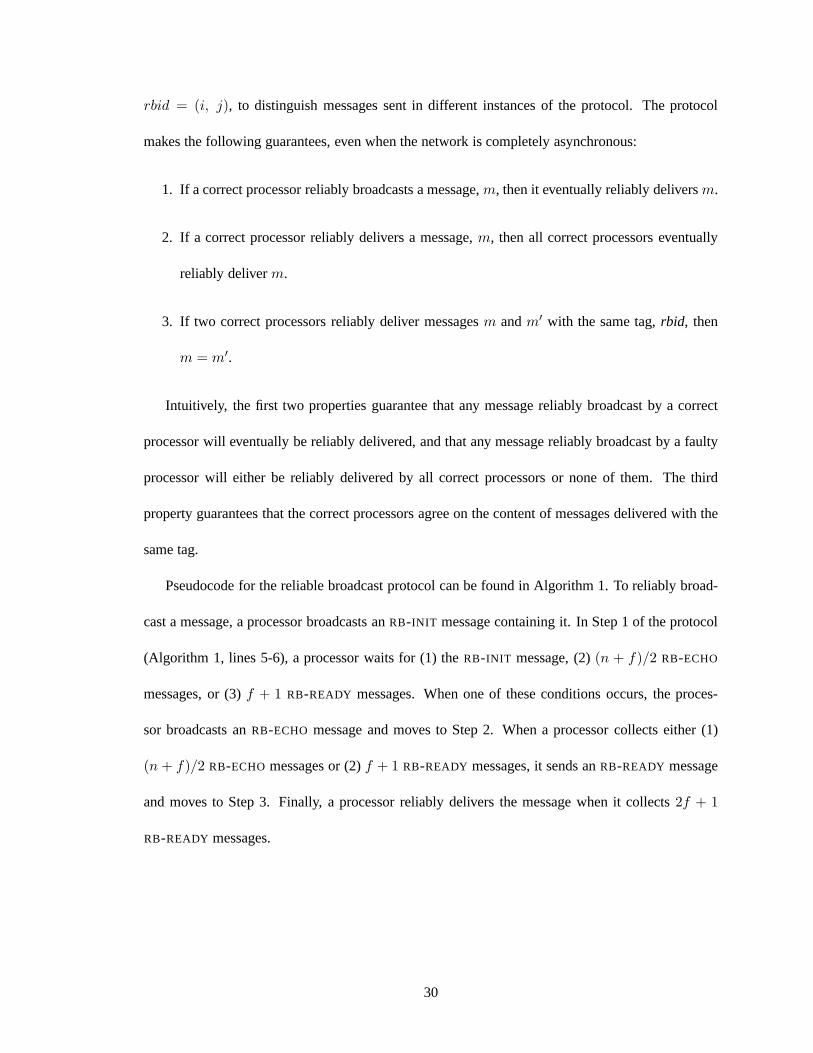
rbid = (i, j), to distinguish messages sent in different instances of theprotocol. The protocol
makes the following guarantees, even when the network is completely asynchronous:
1. If a correct processor reliably broadcasts a message,m, then it eventually reliably deliversm.
2. If a correct processor reliably delivers a message,m, then all correct processors eventually
reliably deliverm.
3. If two correct processors reliably deliver messagesm andm′ with the same tag,rbid, then
m = m′.
Intuitively, the first two properties guarantee that any message reliably broadcast by a correct
processor will eventually be reliably delivered, and that any message reliably broadcast by a faulty
processor will either be reliably delivered by all correct processors or none of them. The third
property guarantees that the correct processors agree on the content of messages delivered with the
same tag.
Pseudocode for the reliable broadcast protocol can be foundin Algorithm 1. To reliably broad-
cast a message, a processor broadcasts anRB-INIT message containing it. In Step 1 of the protocol
(Algorithm 1, lines 5-6), a processor waits for (1) theRB-INIT message, (2)(n + f)/2 RB-ECHO
messages, or (3)f + 1 RB-READY messages. When one of these conditions occurs, the proces-
sor broadcasts anRB-ECHO message and moves to Step 2. When a processor collects either(1)
(n + f)/2 RB-ECHO messages or (2)f + 1 RB-READY messages, it sends anRB-READY message
and moves to Step 3. Finally, a processor reliably delivers the message when it collects2f + 1
RB-READY messages.
30
Algorithm 1 Bracha’s Asynchronous Reliable Broadcast Protocol
1: // Step 0 (Performed by sender only)2: Broadcast:〈RB-INIT , rbid, m〉3:
4: // Step 15: Upon receivingone〈RB-INIT , rbid, m〉message, or(n + f)/2 〈RB-ECHO, rbid, m〉messages,
or (f + 1) 〈RB-READY, rbid, m〉messages6: Broadcast:〈RB-ECHO, rbid, m〉7:
8: // Step 29: Upon receiving (n + f)/2 〈RB-ECHO, rbid, m〉 messages, or(f + 1) 〈RB-READY, rbid, m〉
messages10: Broadcast:〈RB-READY, rbid, m〉11:
12: // Step 313: Upon receiving(2f + 1) 〈RB-READY, rbid, m〉messages14: Reliably deliverm
31
Chapter 3
Performance Under Attack:
A Case Study
This chapter presents a theoretical analysis of Castro and Liskov’s BFT protocol [31], a leader-
based intrusion-tolerant state machine replication protocol, when under attack. We chose BFT
because (1) it is a common protocol to which other Byzantine-resilient protocols are often compared,
(2) many of the attacks that can be applied to BFT (and the corresponding lessons learned) also apply
to other leader-based protocols, and (3) its implementation was publicly available. BFT achieves
high throughput in fault-free executions or when servers exhibit only benign faults. Section 3.1
provides background on BFT. Sections 3.2 and 3.3 then describe two attacks that can be used to
significantly degrade its performance when under attack. Wepresent experimental results validating
the analysis in Section 4.6.
32
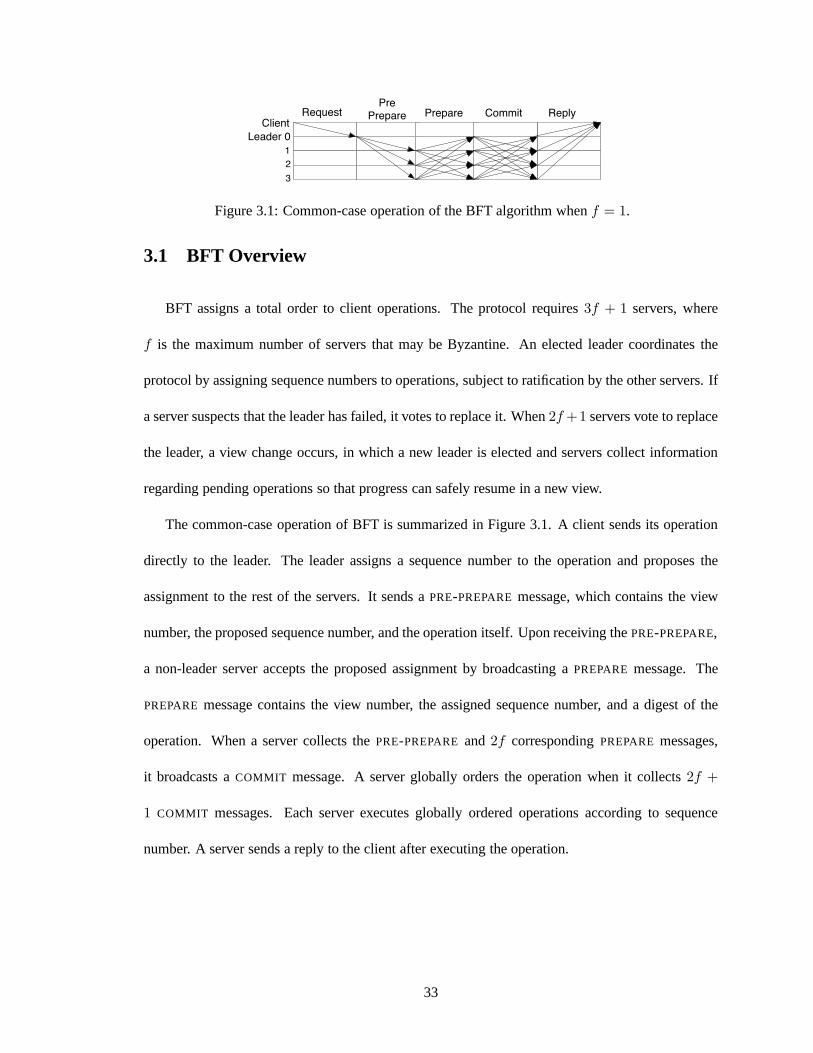
PrePrepare Prepare Commit
ClientRequest Reply
Leader 0
1
2
3
Figure 3.1: Common-case operation of the BFT algorithm whenf = 1.
3.1 BFT Overview
BFT assigns a total order to client operations. The protocolrequires3f + 1 servers, where
f is the maximum number of servers that may be Byzantine. An elected leader coordinates the
protocol by assigning sequence numbers to operations, subject to ratification by the other servers. If
a server suspects that the leader has failed, it votes to replace it. When2f +1 servers vote to replace
the leader, a view change occurs, in which a new leader is elected and servers collect information
regarding pending operations so that progress can safely resume in a new view.
The common-case operation of BFT is summarized in Figure 3.1. A client sends its operation
directly to the leader. The leader assigns a sequence numberto the operation and proposes the
assignment to the rest of the servers. It sends aPRE-PREPAREmessage, which contains the view
number, the proposed sequence number, and the operation itself. Upon receiving thePRE-PREPARE,
a non-leader server accepts the proposed assignment by broadcasting aPREPAREmessage. The
PREPAREmessage contains the view number, the assigned sequence number, and a digest of the
operation. When a server collects thePRE-PREPARE and2f correspondingPREPAREmessages,
it broadcasts aCOMMIT message. A server globally orders the operation when it collects2f +
1 COMMIT messages. Each server executes globally ordered operations according to sequence
number. A server sends a reply to the client after executing the operation.
33
3.2 Attack 1: Pre-Prepare Delay
A malicious leader can introduce latency into the global ordering path simply by waiting some
amount of time after receiving a client operation before sending it in aPRE-PREPAREmessage. The
amount of delay a leader can add without being detected as faulty is dependent on (1) the way in
which non-leaders place timeouts on operations they have not yet executed and (2) the duration of
these timeouts.
A malicious leader can ignore operations sent directly by clients. If a client’s timeout expires
before receiving a reply to its operation, it broadcasts theoperation to all servers, which forward the
operation to the leader. Each non-leader server maintains aFIFO queue of pending operations (i.e.,
those operations it has forwarded to the leader but has not yet executed). A server places a timeout
on the execution of the first operation in its queue; that is, it expects to execute the operation within
the timeout period. If the timeout expires, the server suspects the leader is faulty and votes to replace
it. When a server executes the first operation in its queue, itrestarts the timer if the queue is not
empty. Note that a server does not stop the timer if it executes a pending operation that is not the first
in its queue. The duration of the timeout is dependent on its initial value (which is implementation
and configuration dependent) and the history of past view changes. Servers double the value of their
timeout each time a view change occurs. The specification of BFT does not provide a mechanism
for reducing timeout values.
BFT’s queuing mechanism ensures fairness by guaranteeing that each operation is eventually or-
dered. However, it also allows the leader to significantly delay the ordering of an operation without
being replaced. To retain its role as leader, the leader mustpreventf +1 correct servers from voting
to replace it. Thus, assuming a timeout value ofT, a malicious leader can use the following attack:
(1) Choose a set,S, of f + 1 correct servers, (2) For each serveri ∈ S, maintain a FIFO queue of
the operations forwarded byi, and (3) For each such queue, send aPRE-PREPAREcontaining the
34
first operation on the queue everyT− ǫ time units. This guarantees that thef + 1 correct servers in
S execute the first operation on their queue each timeout period. If these operations are all different,
the fastest the leader would need to introduce operations isat a rate off + 1 per timeout period. In
the worst case, thef + 1 servers would have identical queues, and the leader could introduce one
operation per timeout.
This attack exploits the fact that non-leader servers placetimeouts only on the first operation in
their queues. To understand the ramifications of placing a timeout onall pending operations, we
consider a hypothetical protocol that is identical to BFT except that non-leader servers place a time-
out on all pending operations. Suppose non-leader serveri simultaneously forwardsn operations to
the leader. If serveri sets a timeout on alln operations, theni will suspect the leader if the system
fails to executen operations per timeout period. Since the system has a maximal throughput, ifn
is sufficiently large,i will suspect a correct leader. The fundamental problem is that correct servers
have no way to assess the rate at which a correct leader can coordinate the global ordering.
Recent protocols attempt to mitigate thePRE-PREPAREattack by rotating the leader (an idea
suggested in [11]). The Aardvark protocol [34] forces the current leader to eventually be replaced
by gradually requiring it to meet higher and higher throughput demands. The Spinning protocol
[83] rotates the leader with each batch of operations. Whilethese protocols allow good long-term
throughput and avoid the scenario in which a faulty leader can degrade performance indefinitely,
they do not guarantee that individual operations will be ordered in a timely manner. Prime takes
a different approach, guaranteeing that the system eventually settles on a leader that is forced to
propose an ordering onall operations in a timely manner. To meet this requirement, theleader
needs only a bounded amount of incoming and outgoing bandwidth, independent of the offered
load, which would not be the case if servers placed a timeout on all operations in BFT. As explained
in Section 4.2, Prime bounds the amount of bandwidth required by the leader to propose a timely
35
ordering on all operations by separating the disseminationof the operations from their ordering.
3.3 Attack 2: Timeout Manipulation
One of the main benefits of BFT is that it ensures safety regardless of synchrony assumptions.
The authors justify the need for this property by noting thatdenial of service attacks can be used by
a malicious adversary to violate timing assumptions. Whilea denial of service attack cannot impact
safety, it can be used to increase the timeout value used to detect a faulty leader. During the attack,
the timeout doubles with each view change. If the adversary stops the attack when a malicious
server is the leader, then that leader will be able to slow thesystem down to a throughput of roughly
f + 1 operations per timeoutT , whereT is potentially very large, using the attack described in the
previous section. This vulnerability stems from the inability of BFT to reduce the timeout and adapt
to the network conditions after the system stabilizes.
One might try to overcome this problem in several ways, such as by resetting the timeout to
its default value when the system reaches a view in which progress occurs, or by adapting the
timeout using a multiplicative increase and additive decrease mechanism. In the former approach,
if the timeout is set too low originally, then it will be resetjust when it reaches a large enough
value. This may cause the system to experience long periods during which new operations cannot
be executed, because leaders (even correct ones) continue to be suspected until the timeout becomes
large enough again. The latter approach may be more effective but will be slow to adapt after
periods of instability. As explained in Section 4.3.5, Prime adapts to changing network conditions
and dynamically determines an acceptable level of timeliness based on the current latencies between
correct servers. As stated in Section 4.1, it does so by requiring a slightly stronger degree of network
synchrony for certain key messages.
36
Chapter 4
The Prime Replication Protocol
This chapter presents the Prime replication protocol [17].Prime is the first intrusion-tolerant
state machine replication protocol to guarantee a meaningful level of performance even when some
of the servers exhibit Byzantine faults. This is joint work with Yair Amir, Brian Coan, and John
Lane.
Prime provides a state machine replication service that canbe used to replicate any deterministic
application. The protocol requires at least3f+1 servers, wheref is the maximum number of servers
that may be faulty. Clients submit operations to the servers. An elected leader, chosen dynamically
from among the servers, proposes the order in which the operations should be executed, and the
servers agree on the proposed ordering. By executing the operations in the same order, the servers
remain consistent with one another.
The main challenge that Prime overcomes is limiting the amount of performance degradation
that can be caused by a malicious leader. Prime guarantees that only a leader that assigns an
ordering—in a timely manner and on an ongoing basis—to all client operations known to correct
servers can avoid being replaced. This ensures that the latency of any operation can only be delayed
by a bounded amount of time, and it mitigates attempts by the leader to decrease throughput. In
37
Prime, the amount of delay that can be added by the leader is a function of the current network
delays between the correct servers in the system. These delays cannot be controlled by the faulty
servers. This allows Prime to meet a new performance guarantee, calledBOUNDED-DELAY , when
the system is under attack.
Another challenge that Prime addresses is preventing performance degradation in theview
changeprotocol, which runs when the servers decide to replace a leader they suspect to be faulty.
The view change protocol allows execution to resume safely under the coordination of a new leader
by making sure enough information is exchanged to ensure that decisions made in the new view re-
spect decisions already made in previous views. Previous systems rely on the newly elected leader
to coordinate the view change protocol. We present a new viewchange protocol that takes a differ-
ent approach, relying on the leader only to send a single message that terminates the protocol. This
step is monitored by the non-leader servers using the same technique used to ensure that the leader
proposes a timely ordering during normal-case operation.
The remainder of this chapter is presented as follows. Section 4.1 presents our system model
and describes the service properties that Prime provides. In particular, it defines theBOUNDED-
DELAY correctness property and describes the level of synchrony needed from the network in order
to meet it. Section 4.2 presents an overview of Prime, focusing on the key features of its design and
how they mitigate attempts to cause performance degradation. Section 4.3 describes the technical
details of Prime. The Prime view change protocol is presented in Section 4.4. Section 4.5 sketches
the proof that Prime meetsBOUNDED-DELAY . Section 4.6 evaluates the performance of Prime in
fault-free and under-attack executions. Finally, Section4.7 summarizes the contributions of this
chapter.
38
4.1 System Model and Service Properties
We consider a system consisting ofN servers andM clients, which communicate by passing
messages. Each server is uniquely identified from the setR = {1, 2, . . . , N}, and each client is
uniquely identified from the setS = {N + 1, N + 2, . . . , N + M}. We let the set ofprocessors
be the union of the set of clients and the set of servers. We assume a Byzantine fault model in
which processors are eithercorrect or faulty; correct processors follow the protocol specification
exactly, while faulty processors can deviate from the protocol specification arbitrarily by sending
any message at any time, subject to the cryptographic assumptions stated below. We assume that
N ≥ 3f +1, wheref is an upper bound on the number of servers that may be faulty. For simplicity,
we describe the protocol for the case whenN = 3f + 1. Any number of clients may be faulty.
We assume an asynchronous network, in which message delay for any message is unbounded.
The system meets our safety criteria in all executions in which f or fewer servers are faulty. The
system guarantees our liveness and performance propertiesonly in subsets of the executions in
which message delay satisfies certain constraints. For someof our analysis, we will be interested
in the subset of executions that model Diff-Serv [24] with two traffic classes. To facilitate this
modeling, we allow each correct processor to designate eachmessage that it sends as eitherTIMELY
or BOUNDED.
All messages sent between processors are digitally signed.We denote a message,m, signed
by processori as 〈m〉σi. We assume that digital signatures are unforgeable withoutknowing a
processor’s private key. We also make use of a collision-resistant hash function,D, for computing
message digests. We denote the digest of messagem as D(m). We assume it is computationally
infeasible to find two distinct messages,m andm′, such that D(m) = D(m′).
A client submits anoperationto the system by sending it to one or more servers. Operationsare
classified as read-only (queries) and read/write (updates). Each client operation is signed. There
39
exists a function,Client, known to all processors, that maps each operation to a single client. We say
that an operation,o, is valid if it was signed by the client with identifierClient(o). Correct clients
wait for the reply to their current operation before submitting the next operation. Textually identical
operations are considered multiple instances of the same operation.
Each server produces a sequence of operations,{o1, o2, . . .}, as its output. The output reflects
the order in which the server executes client operations. When a server outputs an operation, it
sends a reply containing the result of the operation to the client.
4.1.1 Safety Properties
The safety properties in Prime constrain the sequence of operations output by correct servers
and define the semantics for replies to operations submittedby correct clients. We now state the
properties.
DEFINITION 4.1.1 Safety-S1: In all executions in whichf or fewer servers are faulty, the output
sequences of two correct servers are identical, or one is a prefix of the other.
DEFINITION 4.1.2 Safety-S2:In all executions in whichf or fewer servers are faulty, each oper-
ation appears in the output sequence of a correct server at most once.
DEFINITION 4.1.3 Safety-S3:In all executions in whichf or fewer servers are faulty, each oper-
ation in the output sequence of a correct server is valid.
Safety-S1implies that operations are totally ordered at correct servers. As in BFT [31], an
optimistic protocol can be used to respond to queries without totally ordering them. The optimistic
protocol may fail if there are concurrent updates, in which case the query can be resubmitted as an
update operation and totally ordered.
40

Server replies for operations submitted by correct clientsare correct according to linearizability
[43], as modified to cope with faulty clients in [30]; we referto this modified semantics asModified-
Linearizability. We say that an operation isinvokedwhen it is first submitted by a client, and it
completeswhen it is output byf + 1 servers. Modified-Linearizability holds for an execution,E,
when the results returned by the service for operations submitted by correct clients are equivalent
to the results returned in some execution,S, in which (1) the operations are atomically executed in
sequence one at a time, and (2) this sequence respects the precedence ordering of non-concurrent
operations inE (i.e., where one operation completes before the next one is invoked). This notion is
captured in the following safety property:
DEFINITION 4.1.4 Safety-S4:In all executions in whichf or fewer servers are faulty, replies for
operations submitted by correct clients satisfy Modified-Linearizability.
4.1.2 Liveness and Performance Properties
Like existing leader-based Byzantine fault-tolerant replication protocols, Prime guarantees live-
ness only in executions in which the network eventually meets certain stability conditions. The
level of stability needed in Prime differs from the level of stability commonly assumed in Byzantine
fault-tolerant replication systems (e.g., [31,34,47]). To facilitate a comparison between the required
stability properties, we specify the following two degreesof synchrony,Eventual-Synchrony[39]
andBounded-Variance. Both are parameterized by a traffic class,T , and a set of processors,S, for
which the stability property holds.Bounded-Varianceis also parameterized by a network-specific
constant,K, that bounds the variance.
DEFINITION 4.1.5 Eventual-Synchrony(T , S): Any message in traffic classT sent from server
s ∈ S to serverr ∈ S will arrive within some unknown bounded time.
41
DEFINITION 4.1.6 Bounded-Variance(T , S, K): For each pair of servers, s and r, in S, there exists
a value, MinLat(s, r), unknown to the servers, such that if s sends a message in traffic class T to r,
it will arrive with delay∆s,r, where MinLat(s, r)≤ ∆s,r ≤ Min Lat(s, r)∗K.
We also make use of the following definition:
DEFINITION 4.1.7 A stable setis a set of correct servers,Stable, such that|Stable| ≥ 2f + 1. We
refer to the members ofStableas thestable servers.
Using the above synchrony specifications, we now define threenetwork stability properties:
DEFINITION 4.1.8 Stability-S1: Let Tall be a traffic class containing all messages. Then there
exists a stable set, Stable, and a time,t, after which Eventual-Synchrony(Tall , Stable) holds.
DEFINITION 4.1.9 Stability-S2: Let Ttimely be a traffic class containing all messages designated
as TIMELY . Then there exists a stable set, Stable, a network-specific constant,KLat, and a time,t,
after which Bounded-Variance(Ttimely , Stable,KLat) holds.
DEFINITION 4.1.10 Stability-S3: Let Ttimely andTbounded be traffic classes containing messages
designated asTIMELY andBOUNDED, respectively. Then there exists a stable set, Stable, a network-
specific constant,KLat, and a time,t, after which Bounded-Variance(Ttimely , Stable,KLat) and
Eventual-Synchrony(Tbounded , Stable) hold.
Note that although the three stability properties are defined as holding from some point on-
ward, in practice we are interested in making statements about the performance and liveness of the
replication systems during periods when the stability properties hold for sufficiently long.
We now specify the liveness guarantees made by existing protocols (using BFT as a representa-
tive example), as well as the one made by Prime:
42
DEFINITION 4.1.11 BFT-LIVENESS: If Stability-S1holds for a stable set,S, and no more thanf
servers are faulty, then if a server inS receives an operation from a correct client, the operation
will eventually be executed by all servers inS.
DEFINITION 4.1.12 PRIME-LIVENESS: If Stability-S2holds for a stable set,S, and no more than
f servers are faulty, then if a server inS receives an operation from a correct client, the operation
will eventually be executed by all servers inS.
Note that the levels of stability needed forBFT-LIVENESS andPRIME-LIVENESS (i.e.,Stability-
S1andStability-S2) are incomparable.BFT-LIVENESS requires a weaker degree of synchrony for
all protocol messages, whilePRIME-LIVENESS requires a stronger degree of synchrony but only
for certain messages; the other messages can arrive completely asynchronously. We discuss the
practical considerations of this difference below.
We now specify a new performance guarantee that Prime meets,calledBOUNDED-DELAY :
DEFINITION 4.1.13 BOUNDED-DELAY : If Stability-S3holds for a stable set,S, and no more than
f servers are faulty, then there exists a time after which the latency between a server inS receiving
a client operation and all servers inS executing that operation is upper bounded.
As we explain in Section 4.5, in Prime, the upper bound is equal to 6L∗bounded +2KLatL
∗timely +
∆, whereL∗timely is the maximum message delay between two stable servers forTIMELY messages;
L∗bounded is the maximum message delay between two stable servers forBOUNDED messages;KLat
is the network-specific constant from Definition 4.1.10; and∆ is an implementation-specific con-
stant accounting for aggregation delays. Intuitively, thetotal latency for the operation is derived
from at most 6 rounds in whichBOUNDED messages are sent, 2 rounds in whichTIMELY messages
are sent, and a constant accounting for aggregation delays.
43

4.1.3 Practical Considerations
We believeStability-S3, which Prime requires to guaranteeBOUNDED-DELAY , can be made
to hold in practical networks. In well-provisioned local-area networks, network delay is often
predictable and queuing is unlikely to occur. To assess the feasibility of meetingStability-S3on
bandwidth-constrained wide-area networks, we must consider the characteristics of theTIMELY
andBOUNDED traffic classes. In Prime, messages in theBOUNDED traffic class account for almost
all of the traffic and assumeEventual-Synchrony, the level of synchrony commonly assumed in
Byzantine fault-tolerant replication systems. Delay is likely to be bounded as long as there is suf-
ficient bandwidth. Once the links become saturated (as the offered load increases), the delay may
become dominated by queuing time.
Messages in theTIMELY traffic class requireBounded-Variance, a stronger degree of synchrony,
but they are only sent periodically and are of small bounded size. On wide-area networks, one could
use a quality of service mechanism such as Diff-Serv [24], with one low-volume class forTIMELY
messages and a second class forBOUNDED messages, to giveStability-S3sufficient coverage, pro-
vided enough bandwidth is available to pass theTIMELY messages without queuing. The required
level of bandwidth is tunable and independent of the offeredload; it is based only on the number of
servers in the system and the rate at which the periodic messages are sent. Thus, in a well-engineered
system,Bounded-Varianceshould hold for messages in theTIMELY traffic class, regardless of the
offered load, because the amount of resources required forTIMELY messages does not grow as the
load increases.
Of course, a Byzantine processor could attempt to flood the network with eitherBOUNDED or
TIMELY messages. This attack can be overcome either by policing thetraffic from processors or by
using sender-specific quality of service classes (as in [63]), allocating a certain amount of resources
to each sender.
44
As noted above, the degree of stability needed for liveness in Prime (i.e.,Stability-S2) is incom-
parable with the degree of stability needed in BFT (i.e.,Stability-S1). In Prime, the only messages
that require synchrony for liveness are those sent in theTIMELY traffic class, which have small
bounded size. In particular, messages that disseminate client operations (which account for the sig-
nificant majority of the traffic) can arrive completely asynchronously. Nevertheless, theTIMELY
messages require a stronger degree of synchrony thanEventual-Synchrony. On the other hand, mes-
sages in BFT require a weaker degree of synchrony for liveness, but this synchrony is assumed to
hold for all protocol messages, including those that disseminate client operations.
In theory, it is possible for a strong network adversary capable of controlling the network vari-
ance to construct scenarios in which BFT is live and Prime is not. These scenarios occur when the
variance forTIMELY messages becomes greater thanKLat, yet the delay is still bounded. This can
be made less likely to occur in practice by increasingKLat, although at the cost of giving a faulty
leader more leeway to cause delay (as explained in Section 4.3.5).
In practice, while the bound on message delay required by BFTand similar protocols can be met
as long as the offered load is finite (i.e., by doubling timeouts until they are long enough), the actual
bound in bandwidth-constrained environments may be dominated by queuing delays, rather than the
actual network latency. To ensure liveness in such protocols, the leader may need enough time to
push throughall offered operations. Increasing the timeout to this degree gives a faulty leader the
power to cause delay. In contrast, sinceStability-S2is only required to hold for a small number of
bounded-size messages, the bound that it implies is more likely to reflect the actual network delays,
allowing the bound to be met while still achieving good performance under attack.
Finally, we remark that resource exhaustion denial of service attacks may causeStability-S3
to be violated for the duration of the attack. Such attacks fundamentally differ from the attacks
that are the focus of this dissertation, where malicious leaders can slow down the system without
45
triggering defense mechanisms (see Chapter 3). Recent work[34] has demonstrated that resource
isolation techniques can be effective in mitigating the impact of flooding-based attacks mounted
by faulty servers and clients. In [34], each pair of servers is connected by a dedicated wire, and a
server uses several network interface cards (one for each server, and a single card for all clients) for
communication. Pending messages are read based on a round-robin scheduling mechanism across
the network interface cards. Handling resource exhaustionattacks at the system-wide level is a
difficult problem that is orthogonal and complementary to the solution strategies considered in this
work.
4.2 Prime: Design and Overview
From a performance perspective, the main goal of Prime is to bound the amount of time between
when a client operation is first received by a correct server and when all of the correct servers execute
the operation, assuming the network is well behaved. In order to meet this goal, Prime is designed so
that a correct leader can propose an ordering on an arbitrarynumber of operations using a bounded
amount of bandwidth and processing resources. The bound is afunction of the number of servers
in the system and is independent of the offered load. Becausethe level of work required from the
leader to propose an ordering on operations is bounded, the non-leader servers can more easily (and
more effectively) judge the leader’s performance. When theleader is seen either to be failing to do
its job or to be doing its job too slowly, it is replaced.
4.2.1 Separating Dissemination from Ordering
In existing leader-based protocols, the ordering of clientoperations is coupled with the dissem-
ination of the operations. For example, in BFT, the leader’sPRE-PREPAREmessages contain a set
of operations and a sequence number indicating where in the global order the operations should be
46
ordered. As the offered load increases, the leader must do more and more work to ensure that opera-
tions are ordered without delay: It must generate an increasing number ofPRE-PREPAREmessages,
and it requires an increasing amount of both incoming and outgoing bandwidth to receive and push
out the operations. This makes it difficult for the non-leader servers to determine how long it should
take between sending an operation to the leader and seeing that the leader has proposed an ordering
on the operation. This difficulty is especially pronounced in bandwidth-constrained environments,
such as wide-area networks, where a correct leader simply might not be able to disseminate opera-
tions quickly enough because it lacks the bandwidth resources. The usual approach to overcoming
this uncertainty is to double the timeout placed on the leader so that correct leaders will eventually
be given enough time and will not be suspected, guaranteeingliveness. However, as noted in Chap-
ter 3, a faulty leader can exploit this uncertainty to delay the ordering of operations and go slower
than it should.
Prime takes a significant departure from existing leader-based protocols by completely separat-
ing the tasks of operation dissemination and operation ordering. In fact, the leader does not even
need to receive a client operation before it can propose an ordering on it. As the offered load in-
creases in Prime, the amount of work required by the leader toensure that operations are ordered
in a timely manner remains the same. The separation of dissemination and ordering allows us to
bound the amount of resources needed by the leader, which in turn enables fine-grained monitoring
of the leader’s performance.
4.2.2 Ordering Strategies
Our overall strategy for establishing a global order on client operations is to have each server
incrementally construct a server-specific ordering of those client operations that it receives. As part
of this server-specific ordering, each server assumes responsibility for disseminating the operations
47

to the other servers. The only thing that the leader must do tobuild the global ordering of client
operations is to incrementally construct an interleaving of the server-specific orderings. In more
detail, the leader constructs the global order by periodically specifying for each server a (possibly
empty) window of additional operations from that server’s server-specific order to add to the global
order. The specified window always starts with the earliest operation from each server that has not
yet been added to the global order.
There are three main challenges in implementing this strategy in the presence of Byzantine
faults. First, the servers must have a way to force the leaderto emit global ordering messages at a
fast enough rate. Second, the servers must be able to verify that each time the leader does expand
the global order it includes the latest operations that havebeen given a server-specific order by each
server. This prevents a malicious leader from intentionally extending the time between when an
operation has been given a server-specific order and when theoperation is assigned a global order.
Third, the leader must only be allowed to extend the global order with operations known widely
enough among the correct servers so that eventually all correct servers will be able to learn what the
operations are. This prevents correct servers from being expected to execute operations known only
by the malicious servers, since such operations may be impossible to recover.
Prime overcomes these challenges while making the leader’sjob of interleaving the server-
specific orderings require only a bounded amount of resources. Each server periodically broadcasts
a bounded-sizesummary messagethat indicates how much of each server’s server-specific ordering
this server has learned about. To extend the global order with the latest operations that have been
given a server-specific order, a correct leader simply needsto periodically send anorderingmessage
containing the most recent summary message from each server. The servers agree on a total order
(across failures) for the leader’s ordering messages. Uponlearning of an ordering message’s place in
the total order, the servers can deterministically map the set of summaries contained in the ordering
48
message to a set of operations which (1) have not already beenoutput in the global order and (2) are
known widely enough among the correct servers so that they can be recovered if necessary. These
operations can then be executed in some deterministic order.
Because the job of extending the global order requires a small, bounded amount of work, the
non-leader servers can effectively monitor the leader’s performance. When a non-leader server
sends a summary message to the leader, it can expect the leader’s next ordering message to reflect
at least as much information about the server-specific orderings as is contained in the summary.
A correct leader’s job is made easy—it simply needs to adopt the summary message if it reflects
more information about the server-specific orderings than what the leader currently knows about.
The non-leader servers measure the round-trip times to eachother to determine how long it should
take between sending a summary to the leader and receiving a corresponding ordering message; we
call this theturnaround timeprovided by the leader. Prime moves on to the next candidate leader
whenever the current leader fails to provide a fast turnaround time (i.e., to propose a timely ordering
on summaries).
Note that there is a distinction between the amount of resources needed by the leader to extend
the global ordering and the amount of resources needed by theleader to disseminate operations from
its own clients. The former is bounded and independent of theoffered load; the latter necessarily in-
creases as more clients send their operations to the leader.As explained below, messages critical to
ensuring timely ordering are sent in theTIMELY traffic class. The leader must be engineered to pro-
cessTIMELY messages as quickly as possible. In general, a well-designed leader should prioritize
its duties as leader above the duties required of leaders andnon-leaders alike (e.g., disseminating
client operations).
49
4.2.3 Mapping Strategies to Sub-Protocols
We now briefly describe how the strategies outlined in the previous section are mapped to sub-
protocols in Prime. Complete technical details are provided in Sections 4.3 and 4.4.
Client Sub-Protocol: The Client sub-protocol defines how a client injects an operation into the
system and collects replies from servers once the operationhas been executed.
Preordering Sub-Protocol: The Preordering sub-protocol implements the server-specific or-
derings that are later interleaved by the leader to construct the global ordering. The sub-protocol
has three main functions. First, it is used to disseminate to2f + 1 servers each client operation that
will ultimately be globally ordered. Second, it is used to bind each operation to a uniquepreorder
identifier, (i, seq), whereseq is the position of the operation in serveri’s server-specific ordering;
we say that a serverpreordersan operation when it learns the operation’s unique binding.Third,
the Preordering sub-protocol summarizes each server’s knowledge of the server-specific orderings
by generating summary messages. A summary generated by server i contains a value,x, for each
serverj such thatx is the longest gap-free prefix of the server-specific ordering generated byj that
is known toi.
Global Ordering Sub-Protocol: The Global Ordering sub-protocol runs periodically and is
used to incrementally extend the global order. The sub-protocol is coordinated by the current leader
and, like BFT [31], establishes a total order onPRE-PREPARE messages. Instead of sending a
PRE-PREPAREmessage containing client operations (or even operation identifiers) like in BFT, the
leader in Prime sends aPRE-PREPAREmessage that contains a vector of at most3f + 1 summary
messages, each from a different server. The summaries contained in the totally ordered sequence of
PRE-PREPAREmessages induce a total order on the preordered operations.
To ensure that client operations known only to faulty processors will not be globally ordered, we
define an operation aseligible for executionwhen the collection of summaries in aPRE-PREPARE
50
message indicate that the operation has been preordered by at least2f+1 servers.1 An operation that
is eligible for execution is known to enough correct serversso that all correct servers will eventually
be able to execute it, regardless of the behavior of faulty servers and clients. Totally ordering a
PRE-PREPAREextends the global order to include those operations that become eligible for the first
time.
Reconciliation Sub-Protocol: The Reconciliation sub-protocol proactively recovers globally
ordered operations known to some servers but not others. Because correct servers can only exe-
cute the gap-free prefix of globally ordered operations, this prevents faulty servers from blocking
execution at some correct servers by intentionally failingto disseminate operations to them. The
intuition behind the problem that motivates the Reconciliation sub-protocol is that although the
Global Ordering sub-protocol guarantees that at least2f + 1 servers have preordered any operation
that becomes eligible for execution, it does not guaranteewhichcorrect servers have preordered a
particular eligible operation. It should be clear that the Global Ordering sub-protocol could not be
modified to require3f + 1 servers to preorder an operation before it becomes eligible, because the
faulty servers might never acknowledge preordering any operations. Therefore, without a reconcil-
iation mechanism, each malicious server could block execution atf correct servers by not sending
an operation to them. Whenf ≥ 3, all correct servers could be blocked, because the number of
servers that could be blocked (f2) would exceed the number of correct servers (2f + 1).
Suspect-Leader Sub-Protocol: Since the leader has to do a bounded amount of work, inde-
pendent of the offered load, to extend the global ordering (i.e., to emit the nextPRE-PREPARE), a
mechanism is needed to ensure that it actually does so. In Suspect-Leader, the servers measure the
round-trip times to each other in order to compute two values. The first is an acceptable turnaround
time that the leader should provide, computed as a function of the latencies between the correct
1We could make an operation eligible for execution whenf + 1 servers have preordered it, but this would make theReconciliation sub-protocol less efficient.
51

servers in the system. The second is a measure of the turnaround time actually being provided by
the leader since its election. The Suspect-Leader sub-protocol guarantees that a leader will be re-
placed unless it provides an acceptable turnaround time to at least one correct server, and that at least
f +1 correct servers will not be suspected (thus ensuring that the protocol is not overly aggressive).
Leader Election Sub-Protocol: When the current leader is suspected to be faulty by enough
servers, the non-leader servers vote to elect a new leader. Leaders are elected by simple rotation,
where the next potential leader is the server with the next server identifier modulo the total number
of servers. Each leader election is associated with a uniqueview number; the resulting configuration,
in which one server is the leader and the rest are non-leaders, is called aview.
View Change Sub-Protocol: When a new leader is elected, the servers run the View Change
sub-protocol to preserve safety across views and to allow monitoring of the new leader’s perfor-
mance to resume without undue delay.
4.3 Prime: Technical Details
This section describes the technical details of the sub-protocols presented in Section 4.2.3. We
defer a discussion of Prime’s View Change sub-protocol until Section 4.4. Table 4.1 lists the mes-
sage types used in each sub-protocol, along with their traffic class and whether they are required to
have synchrony (as specified in Section 4.1) for the system toguarantee liveness.
4.3.1 The Client Sub-Protocol
A client, c, injects an operation into the system by sending a〈CLIENT-OP, o, seq, c〉σc message,
whereo is the operation andseq is a client-specific sequence number, incremented each timethe
client submits an operation, used to ensure exactly-once semantics. The client sets a timeout, during
52
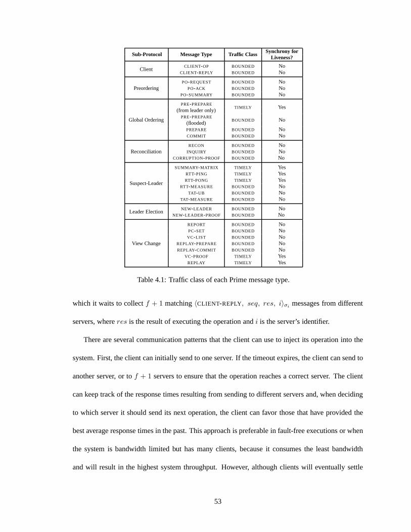
Sub-Protocol Message Type Traffic ClassSynchrony for
Liveness?
ClientCLIENT-OP BOUNDED No
CLIENT-REPLY BOUNDED No
PreorderingPO-REQUEST BOUNDED No
PO-ACK BOUNDED NoPO-SUMMARY BOUNDED No
Global Ordering
PRE-PREPARETIMELY Yes
(from leader only)PRE-PREPARE
BOUNDED No(flooded)PREPARE BOUNDED NoCOMMIT BOUNDED No
ReconciliationRECON BOUNDED No
INQUIRY BOUNDED NoCORRUPTION-PROOF BOUNDED No
Suspect-Leader
SUMMARY-MATRIX TIMELY YesRTT-PING TIMELY YesRTT-PONG TIMELY Yes
RTT-MEASURE BOUNDED NoTAT-UB BOUNDED No
TAT-MEASURE BOUNDED No
Leader ElectionNEW-LEADER BOUNDED No
NEW-LEADER-PROOF BOUNDED No
View Change
REPORT BOUNDED NoPC-SET BOUNDED No
VC-LIST BOUNDED NoREPLAY-PREPARE BOUNDED NoREPLAY-COMMIT BOUNDED No
VC-PROOF TIMELY YesREPLAY TIMELY Yes
Table 4.1: Traffic class of each Prime message type.
which it waits to collectf + 1 matching〈CLIENT-REPLY, seq, res, i〉σimessages from different
servers, whereres is the result of executing the operation andi is the server’s identifier.
There are several communication patterns that the client can use to inject its operation into the
system. First, the client can initially send to one server. If the timeout expires, the client can send to
another server, or tof + 1 servers to ensure that the operation reaches a correct server. The client
can keep track of the response times resulting from sending to different servers and, when deciding
to which server it should send its next operation, the clientcan favor those that have provided the
best average response times in the past. This approach is preferable in fault-free executions or when
the system is bandwidth limited but has many clients, because it consumes the least bandwidth
and will result in the highest system throughput. However, although clients will eventually settle
53
on servers that provide good performance, any individual operation might be delayed if the client
communicates with a faulty server.
To ensure that an operation is introduced by a server in a timely manner, the client can initially
send itsCLIENT-OP message tof + 1 servers. This prevents faulty servers from causing delay
but may result in the operation being orderedf + 1 times. This is safe, because servers use the
sequence number in theCLIENT-OP message to ensure that the operation is executed exactly once.
While providing low latency, this communication pattern may result in lower system throughput
because the system does more work per client operation. For this reason, this approach is preferable
for truly time-sensitive operations or when the system has only a small number of clients.
Finally, we also note that when clients and servers are located on the same machine and hence
share fate, the client can simply send theCLIENT-OP to its local server. In this case, the client can
wait for a single reply: If the client’s server is correct, then the client obtains a correct reply, while
if the client’s server is faulty, the client is considered faulty.
4.3.2 The Preordering Sub-Protocol
As described in Section 4.2.3, the Preordering sub-protocol binds each client operation to a
unique preorder identifier. The preorder identifier consists of a pair of integers,(i, seq), where
i is the identifier of the server that introduces the operationfor preordering, andseq is apreorder
sequence number, a local variable ati incremented each time it introduces an operation for preorder-
ing. Note that the preorder sequence number corresponds to serveri’s server-specific ordering.
Operation Dissemination and Binding: Upon receiving a client operation,o, serveri broad-
casts a〈PO-REQUEST, seqi, o, i〉σimessage. ThePO-REQUESTdisseminates the client’s operation
and proposes that it be bound to the preorder identifier(i, seqi). When a server,j, receives thePO-
REQUEST, it broadcasts a〈PO-ACK, i, seqi, D(o), j〉σjmessage if it has not previously received
54
a PO-REQUESTfrom i with preorder sequence numberseqi.
A set consisting of aPO-REQUESTand2f matchingPO-ACK messages from different servers
constitutes apreorder certificate. The preorder certificate proves that the preorder identifier (i, seqi)
is uniquely bound to client operationo. We say that a server that collects a preorder certificate
preordersthe corresponding operation. The Preordering sub-protocol guarantees that if two servers
bind operationso ando′ to preorder identifier(i, seqi), theno = o′.
Summary Generation and Exchange: Each correct server maintains a local vector,Preorder-
Summary[], indexed by server identifier. At correct serverj, PreorderSummary[i] contains the
maximum sequence number,n, such thatj has preordered all operations bound to preorder identi-
fiers(i, seq), with 1 ≤ seq ≤ n. For example, if server 1 hasPreorderSummary[]= {2, 1, 3, 0},
then server 1 has preordered the client operations bound to preorder identifiers(1, 1) and (1, 2)
from server 1,(2, 1) from server 2,(3, 1), (3, 2), and(3, 3) from server 3, and the server has not
yet preordered any operations introduced by server 4.
Each correct server periodically broadcasts the current state of itsPreorderSummaryvector.
Specifically, serveri broadcasts a〈PO-SUMMARY, vec, i〉σimessage, wherevec is serveri’s local
PreorderSummaryvector. Note that thePO-SUMMARY message serves as a cumulative acknowl-
edgement for preordered operations and is a short representation of every operation the sender has
contiguously preordered (i.e., with no holes) from each server. This type of message is sometimes
called an ARU, or “all received up to,” vector [12].
A key property of the Preordering sub-protocol is that if an operation is introduced for preorder-
ing by a correct server, the faulty servers cannot delay the time at which the operation is cumulatively
acknowledged (inPO-SUMMARY messages) by at least2f + 1 correct servers. This property holds
because the rounds are driven by message exchanges between correct servers.
Each correct server stores the mostup-to-dateandconsistentPO-SUMMARY messages that it
55

Let m1 = 〈PO-SUMMARY, vec1, i〉σi
Let m2 = 〈PO-SUMMARY, vec2, i〉σi
1. m1 is at least as up-to-date asm2 when
• (∀j ∈ R)[vec1[j] ≥ vec2[j]].
2. m1 is more up-to-date thanm2 when
• m1 is at least as up to date asm2, and
• (∃j ∈ R)[vec1[j] > vec2[j]].
3. m1 andm2 areconsistentwhen
• m1 is at least as up to date asm2, or
• m2 is at least as up to date asm1.
Figure 4.1: Terminology used by the Preordering sub-protocol.
has received from each server; these terms are defined formally in Figure 4.1. Intuitively, two
PO-SUMMARY messages from serveri, containing vectorsvec andvec′, are consistent if either all
of the entries invec are greater than or equal to the corresponding entries invec′, or vice versa.
Note that correct servers will never send inconsistentPO-SUMMARY messages, since entries in the
PreorderSummaryvector never decrease. Therefore, a pair of inconsistentPO-SUMMARY messages
from the same server constitutes proof that the server is malicious. Each correct server,i, maintains
a Blacklistdata structure that stores the server identifiers of any servers from whichi has collected
inconsistentPO-SUMMARY messages. We explain the importance of maintaining this blacklist when
we describe the Suspect-Leader sub-protocol in Section 4.3.5.
The collectedPO-SUMMARY messages are stored in a local vector,LastPreorderSummaries[],
indexed by server identifier. In Section 4.3.3, we show how the leader uses the contents of its own
LastPreorderSummariesvector to propose an ordering on preordered operations. In Section 4.3.5,
we show how the non-leaders’LastPreorderSummariesvectors determine what they expect to see
in the leader’s ordering messages, thus allowing them to monitor the leader’s performance.
56
4.3.3 The Global Ordering Sub-Protocol
Protocol Description: Like BFT, the Global Ordering sub-protocol uses three message rounds:
PRE-PREPARE, PREPARE, andCOMMIT. In BFT, thePRE-PREPAREmessages contain and propose
a global order on client operations. In Prime, thePRE-PREPAREmessages contain and propose a
global order onsummary matrices. Each summary matrix is a vector of3f + 1 PO-SUMMARY
messages. The term “matrix” is used because eachPO-SUMMARY message sent by a correct server
itself contains a vector, with each entry reflecting the operations that the server has preordered from
each server. Thus, rowi in summary matrixsm (denotedsm[i]) either contains aPO-SUMMARY
message generated and signed by serveri, or a specialemptyPO-SUMMARY message, containing a
null vector of length3f + 1, indicating that the server has not yet collected aPO-SUMMARY from
serveri. When indexing into a summary matrix, we letsm[i][j] serve as shorthand forsm[i].vec[j].
Observe that, by definition, each server’sLastPreorderSummariesvector is a summary matrix.
A correct leader,l, of view v periodically broadcasts a〈PRE-PREPARE, v, seq, sm, l〉σlmes-
sage, whereseq is a global sequence number (analogous to the one assigned toPRE-PREPARE
messages in BFT) andsm is the leader’sLastPreorderSummariesvector. When correct serveri
receives a〈PRE-PREPARE, v, seq, sm, l〉σlmessage, it takes the following steps. First, serveri
checks eachPO-SUMMARY message in the summary matrix to see if it is consistent with what i
has in itsLastPreorderSummariesvector. Any server whosePO-SUMMARY is inconsistent is added
to i’s Blacklist. Second,i decides if it will respond to thePRE-PREPARE message using similar
logic to the corresponding round in BFT. Specifically,i responds to the message if (1)v is the
current view number and (2)i has not already processed aPRE-PREPAREin view v with the same
sequence number but different content. Ifi decides to respond to thePRE-PREPARE, it broadcasts
a 〈PREPARE, v, seq, D(sm), i〉σlmessage, wherev andseq correspond to the fields in thePRE-
PREPAREandD(sm) is a digest of the summary matrix found in thePRE-PREPARE. A set consisting
57

of aPRE-PREPAREand2f matchingPREPAREmessages constitutes aprepare certificate. Upon col-
lecting a prepare certificate, serveri broadcasts a〈COMMIT, v, seq, D(sm), i〉 message. We say
that a serverglobally ordersa PRE-PREPAREwhen it collects2f + 1 COMMIT messages that match
thePRE-PREPARE.
Obtaining a Global Order on Client Operations: At any time at any correct server, the
current outcome of the Global Ordering sub-protocol is a totally ordered stream ofPRE-PREPARE
messages:T = 〈T1, T2, . . . , Tx〉. The stream at one correct server may be a prefix of the stream at
another correct server, but correct servers do not have inconsistent streams.
We now explain how a correct server obtains a total order on client operations from its current
local value ofT . Let mat be a function that takes aPRE-PREPAREmessage and returns the sum-
mary matrix that it contains. LetM , a function fromPRE-PREPAREmessages to sets of preorder
identifiers, be defined as:
M(Ty) = {(i, seq) : i ∈ R ∧ seq ∈ N ∧ |{j : j ∈ R ∧mat(Ty)[j][i] ≥ seq}| ≥ 2f + 1}
Observe that any preorder identifier inM(Ty) has been associated with a specific operation by
at least2f + 1 servers, of which at leastf + 1 are correct. The Preordering sub-protocol guarantees
that this association is unique. As we describe in Section 4.3.4, any operation inM(Ty) is known to
enough correct servers so that in any sufficiently stable execution, any correct server that does not
yet have the operation will eventually receive it. Note alsothat sincePO-SUMMARY messages are
cumulative acknowledgements, ifM(Ty) contains a preorder identifier(i, seq), thenM(Ty) also
contains all preorder identifiers of the form(i, seq′) for 1 ≤ seq′ < seq.
Let L be a function that takes as input a set of preorder identifiers, P , and outputs the elements
of P ordered lexicographically by their preorder identifiers, with the first element of the preorder
identifier having the higher significance. Letting|| denote concatenation and\ denote set difference,
the final total order on clients operations is obtained by:
58
C1 = L(M(T1))
Cq = L(M(Tq) \M(Tq−1))
C = C1 || C2 || . . . || Cx
Intuitively, when aPRE-PREPAREis globally ordered, it expands the set of preordered operations
that are eligible for execution to include all operationso for which the summary matrix in thePRE-
PREPAREproves that at least2f + 1 servers have preorderedo. Thus, the set difference operation
in the definition of theCq components causes only those operations that have not already become
eligible for execution to be executed.
Pre-Prepare Flooding: We now make a key observation about the Global Ordering sub-
protocol: If all correct servers receive a copy of aPRE-PREPAREmessage, then there is nothing the
faulty servers can do to prevent thePRE-PREPAREfrom being globally ordered in a timely manner.
Progress in thePREPARE and COMMIT rounds is based on collecting sets of2f + 1 messages.
Therefore, since there are at least2f + 1 correct servers, the correct servers are not dependent on
messages from the faulty servers to complete the global ordering.
We leverage this property by having a correct server broadcast aPRE-PREPAREupon receiving
it for the first time. This guarantees that all correct servers receive thePRE-PREPAREwithin one
round from the time that the first correct server receives it,after which no faulty server can delay the
correct servers from globally ordering it. The benefit of this approach is that it forces a malicious
leader to delay sending aPRE-PREPAREto all correct servers in order to add unbounded delay to
the Global Ordering sub-protocol. As described in Section 4.3.5, the Suspect-Leader sub-protocol
results in the replacement of any leader that fails to send a timely PRE-PREPARE to at least one
correct server. This property, combined withPRE-PREPAREflooding, will be used to ensure timely
ordering. We note that in practice, the rate at which the leader sendsPRE-PREPAREmessages can
59
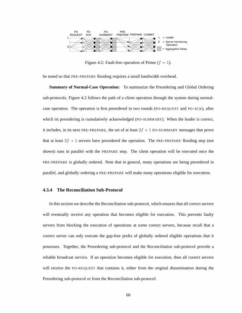
POREQUEST
POACK
POSUMMARY
PREPREPARE PREPARE COMMIT
L
Aggregation Delay
L = Leader
=S
S = Server Introducing Operation
Figure 4.2: Fault-free operation of Prime (f = 1).
be tuned so thatPRE-PREPAREflooding requires a small bandwidth overhead.
Summary of Normal-Case Operation: To summarize the Preordering and Global Ordering
sub-protocols, Figure 4.2 follows the path of a client operation through the system during normal-
case operation. The operation is first preordered in two rounds (PO-REQUESTandPO-ACK), after
which its preordering is cumulatively acknowledged (PO-SUMMARY). When the leader is correct,
it includes, in its nextPRE-PREPARE, the set of at least2f + 1 PO-SUMMARY messages that prove
that at least2f + 1 servers have preordered the operation. ThePRE-PREPAREflooding step (not
shown) runs in parallel with thePREPAREstep. The client operation will be executed once the
PRE-PREPARE is globally ordered. Note that in general, many operations are being preordered in
parallel, and globally ordering aPRE-PREPAREwill make many operations eligible for execution.
4.3.4 The Reconciliation Sub-Protocol
In this section we describe the Reconciliation sub-protocol, which ensures that all correct servers
will eventually receive any operation that becomes eligible for execution. This prevents faulty
servers from blocking the execution of operations at some correct servers, because recall that a
correct server can only execute the gap-free prefix of globally ordered eligible operations that it
possesses. Together, the Preordering sub-protocol and theReconciliation sub-protocol provide a
reliable broadcast service. If an operation becomes eligible for execution, then all correct servers
will receive thePO-REQUEST that contains it, either from the original dissemination during the
Preordering sub-protocol or from the Reconciliation sub-protocol.
60

Algorithm 2 Prime Reconciliation Procedure
1: // Code run at serveri upon receivingPRE-PREPAREwith global sequence numberseq2: pp← 〈PRE-PREPARE, *, seq, sm, l〉σl
3: if seq > 1 then4: pp′← 〈PRE-PREPARE, *, seq − 1, *, l′〉σl′
5: else6: pp′ ← dummyPRE-PREPAREwhose summary matrix contains3f + 1 emptyPO-SUMMARY
messages (each containing a null vector).7: for all preorder identifiers(j, k) in L(M(pp) \M(pp′)) do8: c← 09: for x = 1 to N do
10: if sm[x][j] ≥ k then // Serverx is capable of reconciling(j, k)11: c← c + 112: if x = i and c ≤ 2f + 1 then13: req = 〈PO-REQUEST, k, *, j〉σj
14: part← ErasureEncodedPart(req, c) // Send thecth part15: for r = 1 to N do16: if LastPreorderSummaries[r][j] < k then17: Send to serverr: 〈RECON, j, k, c, part, i〉σi
Protocol Details: Pseudocode for Prime’s reconciliation procedure is contained in Algorithm
2. Conceptually, the Reconciliation sub-protocol operates on the totally ordered sequence of opera-
tions defined by the total orderC = C1 || C2 || . . . || Cx (see Section 4.3.3). Recall that eachCj
is a sequence of preordered operations that became eligiblefor execution with the global ordering
of ppj, the PRE-PREPAREglobally ordered with global sequence numberj. From the wayCj is
created, for each preordered operation(i, seq) in Cj , there exists a set,Ri,seq, of at least2f + 1
servers whosePO-SUMMARY messages cumulatively acknowledged(i, seq) in ppj. The Reconcili-
ation sub-protocol operates by having2f +1 deterministically chosen servers inRi,seq senderasure
encoded partsof the PO-REQUESTcontaining(i, seq) to those servers that have not cumulatively
acknowledged preordering it.
Letting t be the total number of bits in thePO-REQUESTto be sent, Prime uses an(f + 1, 2f +
1, t/(f + 1), f + 1) Maximum Distance Separable erasure-resilient coding scheme (see Section
2.2); that is, thePO-REQUEST is encoded into2f + 1 parts, each1/(f + 1) the size of the original
message, such that anyf + 1 parts are sufficient to decode. Each of the2f + 1 servers inRi,seq
61
sends one part. Since at mostf servers are faulty, this guarantees that a correct server will receive
enough parts to be able to decode thePO-REQUEST.
We note that the only reason the Reconciliation sub-protocol erasure encodes thePO-REQUEST
is for efficiency. The protocol would still work correctly ifeach server inRi,seq sent the entire
PO-REQUEST to each server that has not yet cumulatively acknowledged it. However, this would
consume much more bandwidth and would reduce performance.
The servers run the reconciliation procedure speculatively, when they first receive aPRE-
PREPAREmessage, rather than when they globally order it. This proactive approach allows op-
erations to be recovered in parallel with the remainder of the Global Ordering sub-protocol.
Analysis: Since a correct server will not send a reconciliation message unless at least2f + 1
servers have cumulatively acknowledged the correspondingPO-REQUEST, reconciliation messages
for a given operation are sent to a maximum off servers. Assuming an operation size ofsop,
the2f + 1 erasure encoded parts have a total size of(2f + 1)sop/(f + 1). Since these parts are
sent to at mostf servers, the amount of reconciliation data sent per operation across all links is at
mostf(2f + 1)sop/(f + 1) < (2f + 1)sop. During the Preordering sub-protocol, an operation is
sent to between2f and3f servers, which requires at least2fsop. Therefore, reconciliation uses
approximately the same amount of aggregate bandwidth as operation dissemination. Note that a
single server needs to send at most one reconciliation part per operation, which guarantees that at
leastf + 1 correct servers share the cost of reconciliation.
Blacklisting Faulty Servers: Faulty servers may try to disrupt the reconciliation procedure
by sendingRECON messages that contain invalid erasure encoded parts. An erasure encoded part
is not individually verifiable; it does not contain a proof that it was correctly generated. Therefore,
the Reconciliation sub-protocol requires a mechanism to prevent faulty servers from causing correct
servers to expend computational resources to try to find a setof f + 1 erasure encoded parts that
62
can be decoded to the desired message.
Before describing how we cope with this problem, we note thatonly PO-REQUEST messages
with valid digital signatures can be preordered, because a correct server sends aPO-ACK only after
verifying the correctness of thePO-REQUEST’s digital signature. Since only operations that have
been preordered are cumulatively acknowledged, only validPO-REQUESTmessages will potentially
need to be reconciled. This implies that a correct server candetermine if a decoding succeeded by
verifying the signature on the resultantPO-REQUEST.
The Reconciliation sub-protocol uses a blacklisting mechanism to prevent faulty servers from
repeatedly disrupting the decoding process. The blacklisting protocol ensures that each faulty server
can disrupt the decoding process at most once before it is blacklisted. Subsequent messages from
blacklisted servers are ignored.
Upon detecting a failed decoding, serveri broadcasts an〈INQUIRY, j, k, decodedSet, i〉 mes-
sage, where(j, k) is the preorder identifier of the correspondingPO-REQUESTanddecodedSetis
the set off + 1 signedRECON messages that resulted in the failed decoding. When correctserver
s ∈ Rj,k receives anINQUIRY message fromi, it examines thedecodedSetand compares it to the
parts that it generated to determine if any of the parts are actually invalid. If all of the parts are valid,
then serveri is provably faulty ands can blacklist it. Servers can broadcast aCORRUPTION-PROOF
message, containing thePO-REQUESTand theINQUIRY message, to prove to the other servers that
i is faulty. If one or more erasure encoded parts in theINQUIRY message are invalid, then servers
broadcasts aCORRUPTION-PROOFmessage containing the signed invalid part and the correspond-
ing PO-REQUEST, adding the servers that submitted the invalid parts to the blacklist.
Once a correct server learns that a server is faulty, it should not use that server’sRECONmessages
in subsequent decodings. We require a correct server to learn the outcome of the current inquiry
before making a new inquiry. Therefore, correct servers never generate twoINQUIRY messages that
63

ultimately implicate the same faulty server. Two such messages are proof of corruption, and the
sending server is blacklisted. This prevents faulty servers from generating superfluousINQUIRY
messages that can cause correct servers to consume resources processing them.
4.3.5 The Suspect-Leader Sub-Protocol
The Preordering and Global Ordering sub-protocols enable acorrect leader to propose an order-
ing on an arbitrary number of preordered operations by periodically sendingPRE-PREPAREmes-
sages containing sets ofPO-SUMMARY messages. Moreover, the Reconciliation sub-protocol pre-
vents faulty servers from blocking execution. We now turn tothe problem of how to enforce timely
behavior from the leader of the Global Ordering sub-protocol.
There are two types of performance attacks that can be mounted by a malicious leader. First, it
can sendPRE-PREPAREmessages at a rate slower than the one specified by the protocol. Second,
even if the leader sendsPRE-PREPARE messages at the correct rate, it can intentionally include
a summary matrix that does not contain the most up-to-datePO-SUMMARY messages that it has
received. This can prevent or delay preordered operations from becoming eligible for execution.
The Suspect-Leader sub-protocol is designed to defend against these attacks. The protocol
consists of three mechanisms that work together to enforce timely behavior from the leader:
1. The first mechanism provides a means by which non-leader servers can tell the leader which
PO-SUMMARY messages they expect the leader to include in a subsequentPRE-PREPARE
message.
2. The second mechanism allows the non-leader servers to periodically measure how long it
takes for the leader to send aPRE-PREPAREcontainingPO-SUMMARY messages at least as
up-to-date as those being reported. We call this time theturnaround timeprovided by the
leader, and it is the metric by which the non-leader servers assess the leader’s performance.
64

3. The third mechanism is a distributed protocol by which thenon-leader servers can dynami-
cally determine, based on the current network conditions, how quickly the leader should be
sending up-to-datePRE-PREPAREmessages and decide, based on each server’s measurements
of the leader’s performance, whether to suspect the leader.We call this protocol Suspect-
Leader’sdistributed monitoringprotocol.
In the remainder of this section, we describe each of the mechanisms of Suspect-Leader in more
detail and then prove some of the protocol’s important properties.
Mechanism 1: Reporting the LatestPO-SUMMARY Messages
If the leader is to be expected to sendPRE-PREPAREmessages with the most up-to-datePO-
SUMMARY messages, then each correct server must tell the leader which PO-SUMMARY messages
it believes are the most up-to-date. This explicit notification is necessary because the reception of a
particularPO-SUMMARY message by a correct server does not imply that the leader will receive the
same message—the server that originally sent the message may be faulty. Therefore, each correct
server periodically sends the leader the complete contentsof its LastPreorderSummariesvector.
Specifically, each correct server,i, sends to the leader a〈SUMMARY-MATRIX , sm, i〉σimessage,
wheresm is i’s LastPreorderSummariesvector.
Upon receiving aSUMMARY-MATRIX message, a correct leader updates itsLastPreorderSum-
mariesvector by adopting any of thePO-SUMMARY messages in theSUMMARY-MATRIX message
that are more up-to-date than what the leader currently has in its data structure. SinceSUMMARY-
MATRIX messages have a bounded size dependent only on the number of servers in the system (and
independent of the offered load), the leader requires a small, bounded amount of incoming band-
width and processing resources to learn about the most up-to-datePO-SUMMARY messages in the
system. Furthermore, sincePRE-PREPAREmessages also have a bounded size independent of the
65
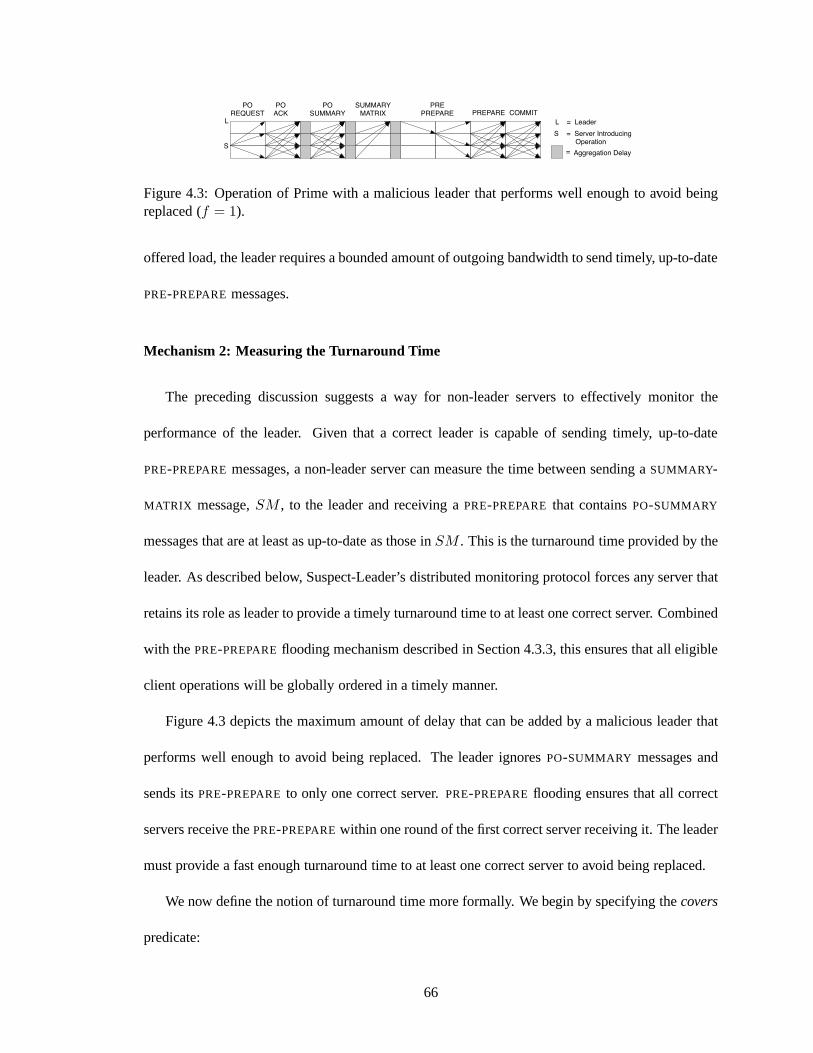
SUMMARYMATRIX
POREQUEST
POACK
POSUMMARY
PREPREPARE PREPARE COMMIT
L
Aggregation Delay
L = Leader
=S
S = Server Introducing Operation
Figure 4.3: Operation of Prime with a malicious leader that performs well enough to avoid beingreplaced (f = 1).
offered load, the leader requires a bounded amount of outgoing bandwidth to send timely, up-to-date
PRE-PREPAREmessages.
Mechanism 2: Measuring the Turnaround Time
The preceding discussion suggests a way for non-leader servers to effectively monitor the
performance of the leader. Given that a correct leader is capable of sending timely, up-to-date
PRE-PREPAREmessages, a non-leader server can measure the time between sending aSUMMARY-
MATRIX message,SM , to the leader and receiving aPRE-PREPARE that containsPO-SUMMARY
messages that are at least as up-to-date as those inSM . This is the turnaround time provided by the
leader. As described below, Suspect-Leader’s distributedmonitoring protocol forces any server that
retains its role as leader to provide a timely turnaround time to at least one correct server. Combined
with thePRE-PREPAREflooding mechanism described in Section 4.3.3, this ensuresthat all eligible
client operations will be globally ordered in a timely manner.
Figure 4.3 depicts the maximum amount of delay that can be added by a malicious leader that
performs well enough to avoid being replaced. The leader ignoresPO-SUMMARY messages and
sends itsPRE-PREPAREto only one correct server.PRE-PREPAREflooding ensures that all correct
servers receive thePRE-PREPAREwithin one round of the first correct server receiving it. Theleader
must provide a fast enough turnaround time to at least one correct server to avoid being replaced.
We now define the notion of turnaround time more formally. We begin by specifying thecovers
predicate:
66
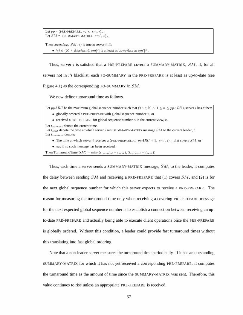
Let pp = 〈PRE-PREPARE, ∗, ∗, sm, ∗〉σ∗
Let SM = 〈SUMMARY-MATRIX , sm′, ∗〉σ∗
Thencovers(pp, SM, i) is true at serveri iff:
• ∀j ∈ (R \ Blacklisti), sm[j] is at least as up-to-date assm′[j].
Thus, serveri is satisfied that aPRE-PREPARE coversa SUMMARY-MATRIX , SM , if, for all
servers not ini’s blacklist, eachPO-SUMMARY in the PRE-PREPARE is at least as up-to-date (see
Figure 4.1) as the correspondingPO-SUMMARY in SM .
We now define turnaround time as follows.
Let ppARU be the maximum global sequence number such that(∀n ∈ N ∧ 1 ≤ n ≤ ppARU), serveri has either:
• globally ordered aPRE-PREPAREwith global sequence numbern, or
• received aPRE-PREPAREfor global sequence numbern in the current view,v.
Let tcurrent denote the current time.Let tsent denote the time at which serveri sentSUMMARY-MATRIX messageSM to the current leader,l.Let treceived denote:
• The time at which serveri receives a〈PRE-PREPARE, v, ppARU + 1, sm′, l〉σlthat coversSM , or
• ∞, if no such message has been received.
Then TurnaroundTime(SM ) = min((treceived − tsent), (tcurrent − tsent))
Thus, each time a server sends aSUMMARY-MATRIX message,SM , to the leader, it computes
the delay between sendingSM and receiving aPRE-PREPARE that (1) coversSM , and (2) is for
the next global sequence number for which this server expects to receive aPRE-PREPARE. The
reason for measuring the turnaround time only when receiving a coveringPRE-PREPAREmessage
for the next expected global sequence number is to establisha connection between receiving an up-
to-datePRE-PREPAREand actually being able to execute client operations once the PRE-PREPARE
is globally ordered. Without this condition, a leader couldprovide fast turnaround times without
this translating into fast global ordering.
Note that a non-leader server measures the turnaround time periodically. If it has an outstanding
SUMMARY-MATRIX for which it has not yet received a correspondingPRE-PREPARE, it computes
the turnaround time as the amount of time since theSUMMARY-MATRIX was sent. Therefore, this
value continues to rise unless an appropriatePRE-PREPAREis received.
67
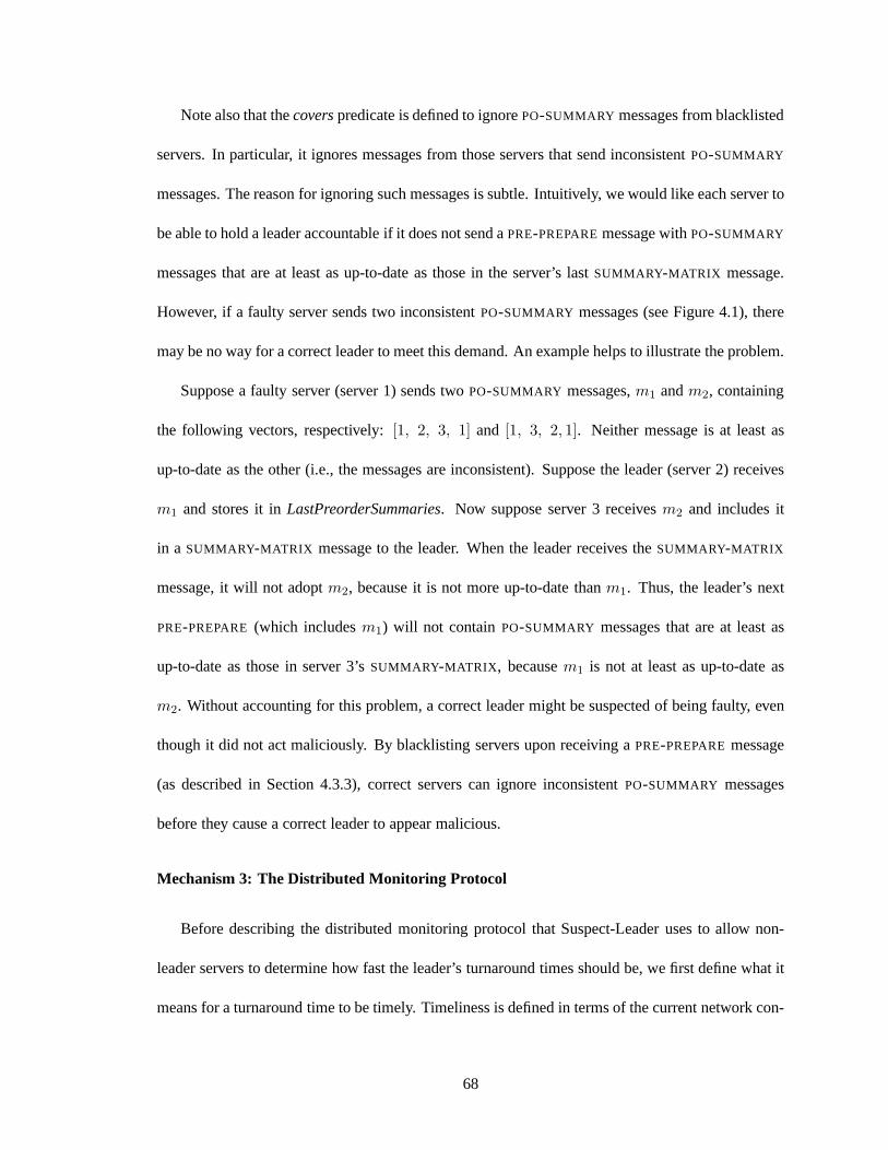
Note also that thecoverspredicate is defined to ignorePO-SUMMARY messages from blacklisted
servers. In particular, it ignores messages from those servers that send inconsistentPO-SUMMARY
messages. The reason for ignoring such messages is subtle. Intuitively, we would like each server to
be able to hold a leader accountable if it does not send aPRE-PREPAREmessage withPO-SUMMARY
messages that are at least as up-to-date as those in the server’s last SUMMARY-MATRIX message.
However, if a faulty server sends two inconsistentPO-SUMMARY messages (see Figure 4.1), there
may be no way for a correct leader to meet this demand. An example helps to illustrate the problem.
Suppose a faulty server (server 1) sends twoPO-SUMMARY messages,m1 andm2, containing
the following vectors, respectively:[1, 2, 3, 1] and [1, 3, 2, 1]. Neither message is at least as
up-to-date as the other (i.e., the messages are inconsistent). Suppose the leader (server 2) receives
m1 and stores it inLastPreorderSummaries. Now suppose server 3 receivesm2 and includes it
in a SUMMARY-MATRIX message to the leader. When the leader receives theSUMMARY-MATRIX
message, it will not adoptm2, because it is not more up-to-date thanm1. Thus, the leader’s next
PRE-PREPARE (which includesm1) will not contain PO-SUMMARY messages that are at least as
up-to-date as those in server 3’sSUMMARY-MATRIX , becausem1 is not at least as up-to-date as
m2. Without accounting for this problem, a correct leader might be suspected of being faulty, even
though it did not act maliciously. By blacklisting servers upon receiving aPRE-PREPAREmessage
(as described in Section 4.3.3), correct servers can ignoreinconsistentPO-SUMMARY messages
before they cause a correct leader to appear malicious.
Mechanism 3: The Distributed Monitoring Protocol
Before describing the distributed monitoring protocol that Suspect-Leader uses to allow non-
leader servers to determine how fast the leader’s turnaround times should be, we first define what it
means for a turnaround time to be timely. Timeliness is defined in terms of the current network con-
68

ditions and the rate at which a correct leader would sendPRE-PREPAREmessages. In the definition
that follows, we letL∗timely denote the maximum latency for aTIMELY message sent between any
two correct servers;∆pp denote a value greater than the maximum time between a correct server
sending successivePRE-PREPAREmessages; andKLat be a network-specific constant accounting
for latency variability.
PROPERTY 4.3.1 If Stability-S2 holds, then any server that retains a role asleader must provide a
turnaround time to at least one correct server that is no morethanB = 2KLatL∗timely + ∆pp.
Property 4.3.1 ensures that a faulty leader will be suspected unless it provides a timely
turnaround time to at least one correct server. We consider aturnaround time,t ≤ B, to be timely
becauseB is within a constant factor of the turnaround time that the slowest correct server might
provide. The factor is a function of the latency variabilitythat Suspect-Leader is configured to toler-
ate. Note that malicious servers cannot affect the value ofB, and that increasing the value ofKLat
gives the leader more power to cause delay.
Of course, it is important to make sure that Suspect-Leader is not overly aggressive in the time-
liness it requires from the leader. The following property ensures that this is the case:
PROPERTY 4.3.2 If Stability-S2 holds, then there exists a set of at leastf + 1 correct servers that
will not be suspected by any correct server if elected leader.
Property 4.3.2 ensures that when the network is sufficientlystable, view changes cannot occur
indefinitely. Prime does not guarantee that the slowestf correct servers will not be suspected
because slow faulty leaders cannot be distinguished from slow correct leaders.
We now present Suspect-Leader’s distributed monitoring protocol. The distributed monitoring
protocol allows non-leader servers to dynamically determine how fast a turnaround time the leader
should provide and to suspect the leader if it is not providing a fast enough turnaround time to at
least one correct server. Pseudocode for the protocol is contained in Algorithm 3.
69
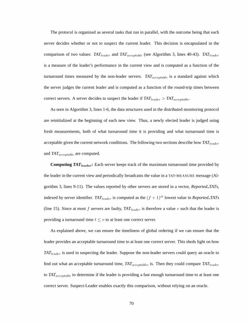
The protocol is organized as several tasks that run in parallel, with the outcome being that each
server decides whether or not to suspect the current leader.This decision is encapsulated in the
comparison of two values:TATleader andTATacceptable (see Algorithm 3, lines 40-43).TATleader
is a measure of the leader’s performance in the current view and is computed as a function of the
turnaround times measured by the non-leader servers.TATacceptable is a standard against which
the server judges the current leader and is computed as a function of the round-trip times between
correct servers. A server decides to suspect the leader ifTATleader > TATacceptable.
As seen in Algorithm 3, lines 1-6, the data structures used inthe distributed monitoring protocol
are reinitialized at the beginning of each new view. Thus, a newly elected leader is judged using
fresh measurements, both of what turnaround time it is providing and what turnaround time is
acceptable given the current network conditions. The following two sections describe howTATleader
andTATacceptable are computed.
Computing TATleader: Each server keeps track of the maximum turnaround time provided by
the leader in the current view and periodically broadcasts the value in aTAT-MEASURE message (Al-
gorithm 3, lines 9-11). The values reported by other serversare stored in a vector,ReportedTATs,
indexed by server identifier.TATleader is computed as the(f + 1)st lowest value inReportedTATs
(line 15). Since at mostf servers are faulty,TATleader is therefore a valuev such that the leader is
providing a turnaround timet ≤ v to at least one correct server.
As explained above, we can ensure the timeliness of global ordering if we can ensure that the
leader provides an acceptable turnaround time to at least one correct server. This sheds light on how
TATleader is used in suspecting the leader. Suppose the non-leader servers could query an oracle to
find out what an acceptable turnaround time,TATacceptable, is. Then they could compareTATleader
to TATacceptable to determine if the leader is providing a fast enough turnaround time to at least one
correct server. Suspect-Leader enables exactly this comparison, without relying on an oracle.
70
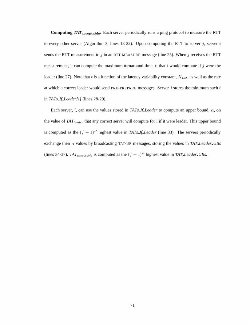
Computing TATacceptable: Each server periodically runs a ping protocol to measure theRTT
to every other server (Algorithm 3, lines 18-22). Upon computing the RTT to serverj, serveri
sends the RTT measurement toj in anRTT-MEASURE message (line 25). Whenj receives the RTT
measurement, it can compute the maximum turnaround time,t, thati would compute ifj were the
leader (line 27). Note thatt is a function of the latency variability constant,KLat, as well as the rate
at which a correct leader would sendPRE-PREPAREmessages. Serverj stores the minimum sucht
in TATsIf Leader[i] (lines 28-29).
Each server,i, can use the values stored inTATsIf Leaderto compute an upper bound,α, on
the value ofTATleader that any correct server will compute fori if it were leader. This upper bound
is computed as the(f + 1)st highest value inTATsIf Leader(line 33). The servers periodically
exchange theirα values by broadcastingTAT-UB messages, storing the values inTAT LeaderUBs
(lines 34-37).TATacceptable is computed as the(f + 1)st highest value inTAT LeaderUBs.
71
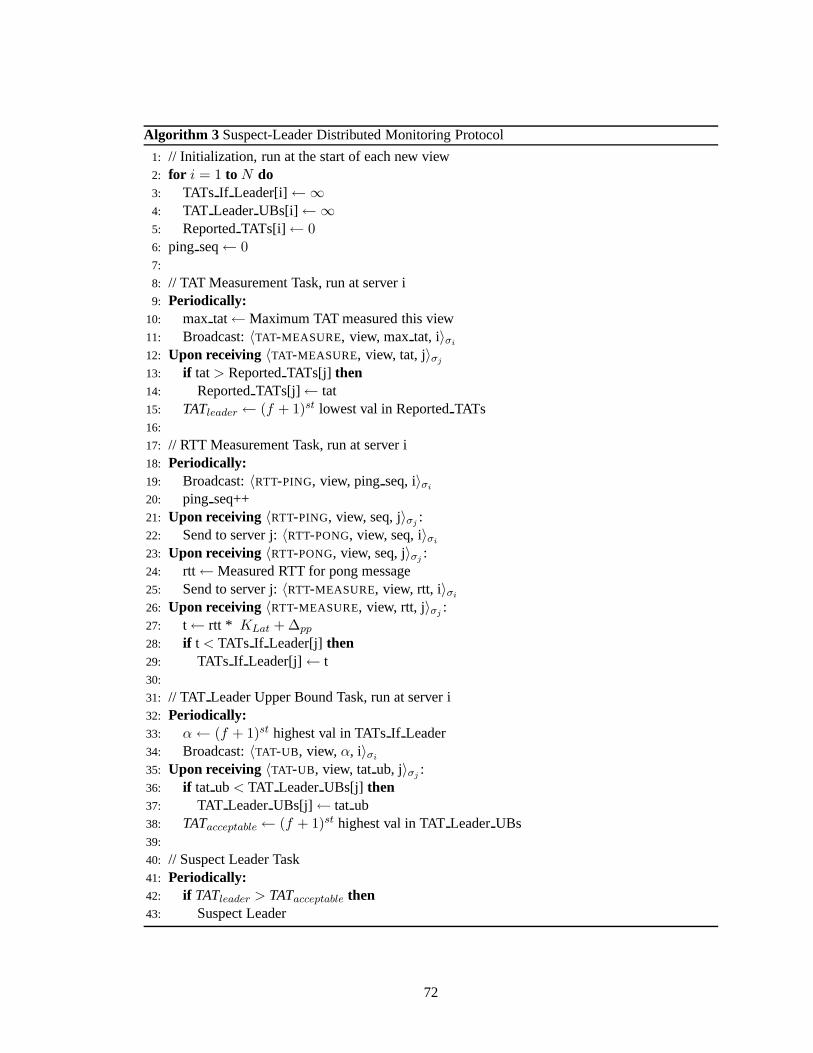
Algorithm 3 Suspect-Leader Distributed Monitoring Protocol
1: // Initialization, run at the start of each new view2: for i = 1 to N do3: TATs If Leader[i]←∞4: TAT LeaderUBs[i] ←∞5: ReportedTATs[i] ← 06: ping seq← 07:
8: // TAT Measurement Task, run at server i9: Periodically:
10: max tat← Maximum TAT measured this view11: Broadcast:〈TAT-MEASURE, view, maxtat, i〉σi
12: Upon receiving〈TAT-MEASURE, view, tat, j〉σj
13: if tat> ReportedTATs[j] then14: ReportedTATs[j] ← tat15: TATleader ← (f + 1)st lowest val in ReportedTATs16:
17: // RTT Measurement Task, run at server i18: Periodically:19: Broadcast:〈RTT-PING, view, ping seq, i〉σi
20: ping seq++21: Upon receiving〈RTT-PING, view, seq, j〉σj
:22: Send to server j:〈RTT-PONG, view, seq, i〉σi
23: Upon receiving〈RTT-PONG, view, seq, j〉σj:
24: rtt← Measured RTT for pong message25: Send to server j:〈RTT-MEASURE, view, rtt, i〉σi
26: Upon receiving〈RTT-MEASURE, view, rtt, j〉σj:
27: t← rtt * KLat + ∆pp
28: if t < TATs If Leader[j] then29: TATs If Leader[j]← t30:
31: // TAT Leader Upper Bound Task, run at server i32: Periodically:33: α← (f + 1)st highest val in TATsIf Leader34: Broadcast:〈TAT-UB, view,α, i〉σi
35: Upon receiving〈TAT-UB, view, tat ub, j〉σj:
36: if tat ub< TAT LeaderUBs[j] then37: TAT LeaderUBs[j] ← tat ub38: TATacceptable← (f + 1)st highest val in TATLeaderUBs39:
40: // Suspect Leader Task41: Periodically:42: if TATleader > TATacceptable then43: Suspect Leader
72
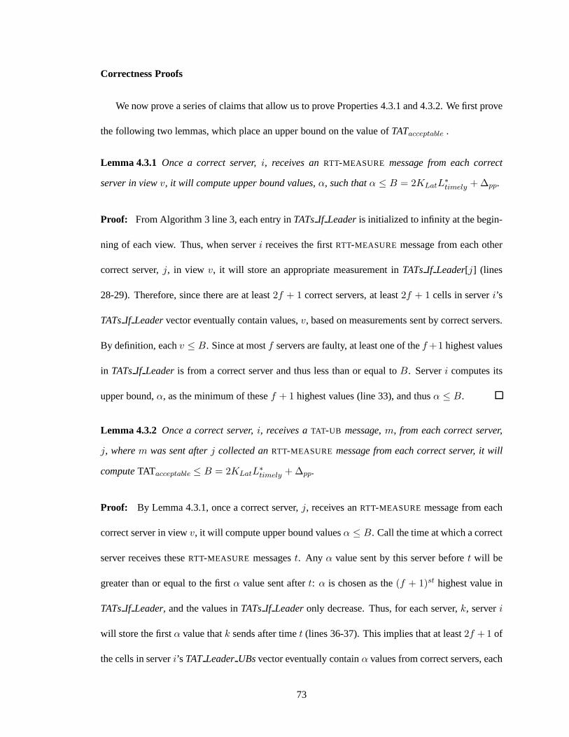
Correctness Proofs
We now prove a series of claims that allow us to prove Properties 4.3.1 and 4.3.2. We first prove
the following two lemmas, which place an upper bound on the value ofTATacceptable .
Lemma 4.3.1 Once a correct server,i, receives anRTT-MEASURE message from each correct
server in viewv, it will compute upper bound values,α, such thatα ≤ B = 2KLatL∗timely + ∆pp.
Proof: From Algorithm 3 line 3, each entry inTATsIf Leaderis initialized to infinity at the begin-
ning of each view. Thus, when serveri receives the firstRTT-MEASURE message from each other
correct server,j, in view v, it will store an appropriate measurement inTATsIf Leader[j] (lines
28-29). Therefore, since there are at least2f + 1 correct servers, at least2f + 1 cells in serveri’s
TATsIf Leadervector eventually contain values,v, based on measurements sent by correct servers.
By definition, eachv ≤ B. Since at mostf servers are faulty, at least one of thef +1 highest values
in TATsIf Leaderis from a correct server and thus less than or equal toB. Serveri computes its
upper bound,α, as the minimum of thesef + 1 highest values (line 33), and thusα ≤ B.
Lemma 4.3.2 Once a correct server,i, receives aTAT-UB message,m, from each correct server,
j, wherem was sent afterj collected anRTT-MEASURE message from each correct server, it will
computeTATacceptable ≤ B = 2KLatL∗timely + ∆pp.
Proof: By Lemma 4.3.1, once a correct server,j, receives anRTT-MEASURE message from each
correct server in viewv, it will compute upper bound valuesα ≤ B. Call the time at which a correct
server receives theseRTT-MEASURE messagest. Any α value sent by this server beforet will be
greater than or equal to the firstα value sent aftert: α is chosen as the(f + 1)st highest value in
TATsIf Leader, and the values inTATsIf Leaderonly decrease. Thus, for each server,k, serveri
will store the firstα value thatk sends after timet (lines 36-37). This implies that at least2f + 1 of
the cells in serveri’s TAT LeaderUBsvector eventually containα values from correct servers, each
73
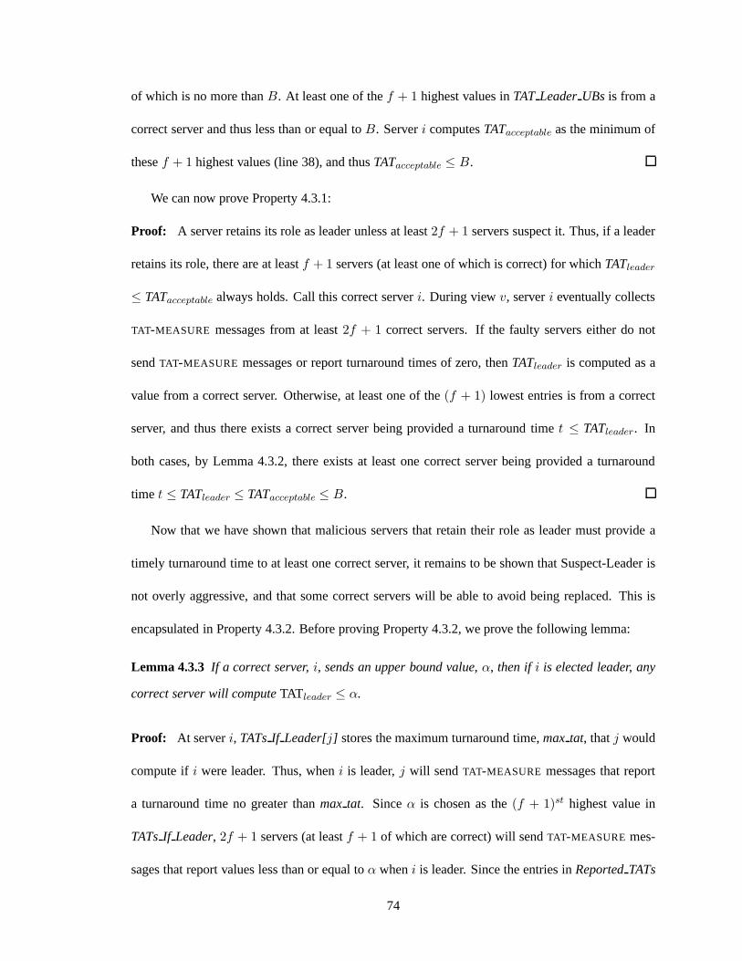
of which is no more thanB. At least one of thef + 1 highest values inTAT LeaderUBs is from a
correct server and thus less than or equal toB. Serveri computesTATacceptable as the minimum of
thesef + 1 highest values (line 38), and thusTATacceptable ≤ B.
We can now prove Property 4.3.1:
Proof: A server retains its role as leader unless at least2f + 1 servers suspect it. Thus, if a leader
retains its role, there are at leastf + 1 servers (at least one of which is correct) for whichTATleader
≤ TATacceptable always holds. Call this correct serveri. During viewv, serveri eventually collects
TAT-MEASURE messages from at least2f + 1 correct servers. If the faulty servers either do not
sendTAT-MEASURE messages or report turnaround times of zero, thenTATleader is computed as a
value from a correct server. Otherwise, at least one of the(f + 1) lowest entries is from a correct
server, and thus there exists a correct server being provided a turnaround timet ≤ TATleader. In
both cases, by Lemma 4.3.2, there exists at least one correctserver being provided a turnaround
time t ≤ TATleader ≤ TATacceptable ≤ B.
Now that we have shown that malicious servers that retain their role as leader must provide a
timely turnaround time to at least one correct server, it remains to be shown that Suspect-Leader is
not overly aggressive, and that some correct servers will beable to avoid being replaced. This is
encapsulated in Property 4.3.2. Before proving Property 4.3.2, we prove the following lemma:
Lemma 4.3.3 If a correct server,i, sends an upper bound value,α, then ifi is elected leader, any
correct server will computeTATleader ≤ α.
Proof: At serveri, TATsIf Leader[j] stores the maximum turnaround time,max tat, thatj would
compute ifi were leader. Thus, wheni is leader,j will send TAT-MEASURE messages that report
a turnaround time no greater thanmax tat. Sinceα is chosen as the(f + 1)st highest value in
TATsIf Leader, 2f + 1 servers (at leastf + 1 of which are correct) will sendTAT-MEASURE mes-
sages that report values less than or equal toα wheni is leader. Since the entries inReportedTATs
74
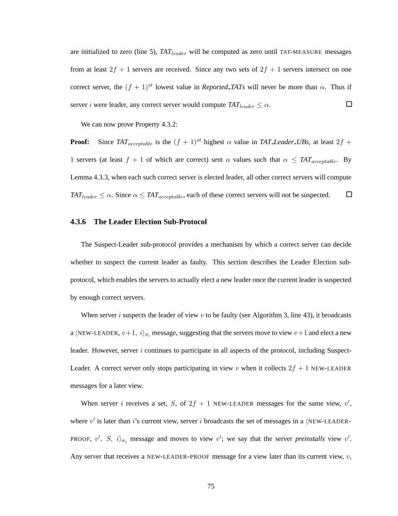
are initialized to zero (line 5),TATleader will be computed as zero untilTAT-MEASURE messages
from at least2f + 1 servers are received. Since any two sets of2f + 1 servers intersect on one
correct server, the(f + 1)st lowest value inReportedTATswill never be more thanα. Thus if
serveri were leader, any correct server would computeTATleader ≤ α.
We can now prove Property 4.3.2:
Proof: SinceTATacceptable is the (f + 1)st highestα value inTAT LeaderUBs, at least2f +
1 servers (at leastf + 1 of which are correct) sentα values such thatα ≤ TATacceptable. By
Lemma 4.3.3, when each such correct server is elected leader, all other correct servers will compute
TATleader ≤ α. Sinceα ≤ TATacceptable, each of these correct servers will not be suspected.
4.3.6 The Leader Election Sub-Protocol
The Suspect-Leader sub-protocol provides a mechanism by which a correct server can decide
whether to suspect the current leader as faulty. This section describes the Leader Election sub-
protocol, which enables the servers to actually elect a new leader once the current leader is suspected
by enough correct servers.
When serveri suspects the leader of viewv to be faulty (see Algorithm 3, line 43), it broadcasts
a〈NEW-LEADER, v+1, i〉σimessage, suggesting that the servers move to viewv+1 and elect a new
leader. However, serveri continues to participate in all aspects of the protocol, including Suspect-
Leader. A correct server only stops participating in viewv when it collects2f + 1 NEW-LEADER
messages for a later view.
When serveri receives a set,S, of 2f + 1 NEW-LEADER messages for the same view,v′,
wherev′ is later thani’s current view, serveri broadcasts the set of messages in a〈NEW-LEADER-
PROOF, v′, S, i〉σimessage and moves to viewv′; we say that the serverpreinstalls view v′.
Any server that receives aNEW-LEADER-PROOFmessage for a view later than its current view,v,
75

immediately stops participating in viewv and preinstalls viewv′. It also periodically broadcasts
theNEW-LEADER-PROOFmessage for viewv′ and continues to do so until it moves to a new view.
Broadcasting theNEW-LEADER-PROOFensures that all correct servers preinstall viewv′ within one
round of the first correct server preinstalling viewv′. When a server preinstalls viewv′, it begins
running the View Change sub-protocol described in Section 4.4.
The reason why a correct server continues to participate in view v even after suspecting the
leader of viewv is to prevent a scenario in which a leader retains its role as leader (by sending
timely, up-to-datePRE-PREPAREmessages to enough correct servers) but the servers are unable to
globally order thePRE-PREPAREmessages. If a correct server could become silent in viewv without
knowing that a new leader will be elected, then if the leader does retain its role and the faulty servers
become silent, thePRE-PREPAREmessages would not be able to garner2f + 1 PREPAREmessages
and ultimately be globally ordered. The approach taken by the Leader Election sub-protocol is
similar to the one used by Zyzzyva [47], where correct servers continue to participate in a view until
they collectf + 1 I-HATE-THE-PRIMARY messages.
Note that the messages sent in the Leader Election sub-protocol are in theBOUNDED traffic
class. In particular, they do not require synchrony for Prime to meet its liveness guarantee. The
Leader Election sub-protocol uses the reception of messages, and not timeouts, to clock the progress
of the protocol. As described in Section 4.4, the View Changesub-protocol also uses the reception
of messages to clock the progress of the protocol, except forthe last step, where messages must be
timely and the servers resume running Suspect-Leader to ensure that the protocol terminates without
delay.
76

4.4 The Prime View Change Protocol
In order for theBOUNDED-DELAY property to be useful in practice, the time at which it begins
to hold (after the network stabilizes) should not be able to be set arbitrarily far into the future by the
faulty servers. As we now illustrate, achieving this requirement necessitates a different style of view
change protocol than the one used by BFT, Zyzzyva, and other existing leader-based protocols.
4.4.1 Background: BFT’s View Change Protocol
To facilitate a comparison between Prime’s view change protocol and the ones used by exist-
ing protocols, we review the BFT view change protocol. A newly elected leader collects state from
2f +1 servers in the form ofVIEW-CHANGE messages, processes these messages, and subsequently
broadcasts aNEW-VIEW message. TheNEW-VIEW contains the set of2f + 1 VIEW-CHANGE mes-
sages, as well as a set ofPRE-PREPARE messages thatreplay pending operations that may have
been ordered by some, but not all, correct servers in a previous view. TheVIEW-CHANGE messages
allow the non-leader servers to verify that the leader constructed the set ofPRE-PREPAREmessages
properly. We refer to the contents of theNEW-VIEW as theconstraining statefor this view.
Although theVIEW-CHANGE andNEW-VIEW messages are logically single messages, they may
be large, and thus the non-leader servers cannot determine exactly how long it should take for
the leader to receive and disseminate the necessary state. Anon-leader server sets a timeout on
suspecting the leader when it learns of the leader’s election, and it expires the timeout if it does not
receive theNEW-VIEW or does not execute the first operation on its queue within thetimeout period.
The timeout used for suspecting the current leader doubles with every view change, guaranteeing
that correct leaders eventually have enough time to complete the protocol.
77
4.4.2 Motivation and Protocol Overview
The view change protocol outlined above is insufficient for Prime. Doubling the timeouts greatly
increases the power of the faulty servers; if the timeout grows very high during unstable periods,
then a faulty leader can cause the view change to take much longer than it would take with a correct
leader. If Prime were to use such a protocol, then the faulty servers could delay the time at which
BOUNDED-DELAY begins to hold by increasing the duration of the view changesin which they are
leader. The amount of the delay would be a function of how manyview changes occurred in the
past, which can be manipulated by causing view changes during unstable periods (e.g., by using a
denial of service attack).
To overcome this issue, Prime uses a different approach for its view change protocol. Whereas
BFT’s protocol is primarily coordinated by the leader, Prime’s view change protocol is designed to
rely on the leader as little as possible. The key observationis that the leader neither needs to collect
view change state from2f + 1 servers nor disseminate constraining state to the non-leader servers
in order to fulfill its role as leader. Instead, the leader canconstrain non-leader servers simply by
sending a single physical message that identifies which viewchange state messages should consti-
tute the constraining state. Thus, instead of being responsible for state collection, processing, and
dissemination, the leader is only responsible for making a single decision and sending a single mes-
sage (which we call the leader’sREPLAY message). The challenge is to construct the view change
protocol in a way that will allow non-leader servers to forcethe leader to send a validREPLAY
message in a timely manner.
How can a single physical message identify the many view change state messages that con-
stitute the constraining state? Each server disseminates its view change state using a Byzantine
fault-tolerant reliable broadcast protocol (e.g., [26]);we provide background on the asynchronous
reliable broadcast protocol used by the RITAS implementation, which was originally proposed by
78
Bracha [26], in Section 2.3. The reliable broadcast protocol guarantees that all servers that collect
view change state from any serveri in view v collect exactly the same state. In addition, if any
correct server collects view change state from serveri in view v, then all correct servers eventually
will do so. Given these properties, the leader’sREPLAY message simply needs to contain a list of
2f + 1 server identifiers in order to unambiguously identify the constraining state. For example,
if the leader’sREPLAY message contains the list〈1, 3, 4〉, then the view change state disseminated
by servers1, 3, and4 should be used to become constrained. As described below, the REPLAY
message also contains a proof that all of the referenced viewchange state messages will eventually
be delivered to all correct servers.
A critical property of the reliable broadcast protocol usedfor view change state dissemination
is that it cannot be slowed down by the faulty servers. Correct servers only need to send and receive
messages from one another in order to complete the protocol.Therefore, the state dissemination
phase takes as much time as is required for correct servers topass the necessary information between
one another, and no longer.
If the leader is faulty, it can send aREPLAY message whose list contains faulty servers, from
which it may be impossible to collect view change state. Thus, the protocol requires that the leader’s
list be verifiable, which we achieve by using a threshold signature protocol. Once a server finishes
collecting view change state from2f + 1 servers, it announces a list containing their server identi-
fiers. A server submits a partial signature on a list,L, if it has finished collecting view change state
from the2f + 1 servers inL. The servers combine2f + 1 matching partial signatures into a thresh-
old signature onL; we refer to the pair consisting ofL and its threshold signature as aVC-Proof. At
least one correct server (in fact,f + 1 correct servers) must have submitted a partial signature onL,
which, by the properties of reliable broadcast, implies that all correct servers will eventually finish
collecting view change state from the servers inL. Thus, by including a VC-Proof in itsREPLAY,
79
the leader can convince the non-leader servers that they will eventually collect the state from the
servers in the list.
We note that instead of generating a threshold-signed proof, the leader could also include a set
of 2f + 1 signed messages to prove the correctness of theREPLAY message. While this may be
conceptually simpler and somewhat less computationally expensive, using threshold signatures has
the desirable property that the resulting proof is compact and can fit in a single physical message,
which may allow for more effective performance monitoring in bandwidth-constrained environ-
ments. Both types of proof provide the same level of guarantee regarding the correctness of the
REPLAY message.
The last remaining challenge is to ensure that the leader sends itsREPLAY message in a timely
manner. The key property of the protocol is that the leader can immediately use a VC-Proof to
generate theREPLAY message,even if it has not yet collected view change state from the servers in
the list. Thus, after a non-leader server sends a VC-Proof to the leader, it can expect to receive the
REPLAY message in a timely fashion. We integrate the computation ofthis turnaround time (i.e.,
the time between sending a VC-Proof to the leader and receiving a validREPLAY message) into the
normal-case Suspect-Leader protocol to monitor the leader’s behavior. By using Suspect-Leader to
ensure that the leader terminates the view change in a timelymanner, we avoid the use of a timeout
and its associated vulnerabilities. Table 4.2 summarizes Prime’s view change protocol.
4.4.3 Detailed Protocol Description
Preliminaries: When a server learns that a new leader has been elected in viewv, we say that
it preinstallsview v. As described above, the Prime view change protocol uses an asynchronous
Byzantine fault-tolerant reliable broadcast protocol forstate dissemination. We assume that the
identifiers used in the reliable broadcast are of the form〈i, v, seq〉, wherev is the preinstalled view
80
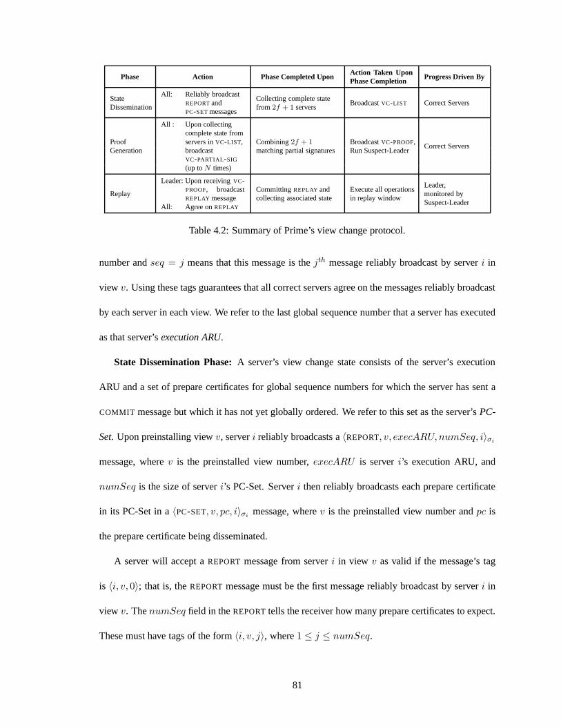
Phase Action Phase Completed UponAction Taken UponPhase Completion
Progress Driven By
StateDissemination
All: Reliably broadcastREPORTandPC-SETmessages
Collecting complete statefrom 2f + 1 servers
BroadcastVC-LIST Correct Servers
ProofGeneration
All : Upon collectingcomplete state fromservers inVC-LIST,broadcastVC-PARTIAL-SIG
(up toN times)
Combining2f + 1matching partial signatures
BroadcastVC-PROOF,Run Suspect-Leader
Correct Servers
Replay
Leader: Upon receivingVC-PROOF, broadcastREPLAY message
CommittingREPLAY andcollecting associated state
Execute all operationsin replay window
Leader,monitored bySuspect-Leader
All: Agree onREPLAY
Table 4.2: Summary of Prime’s view change protocol.
number andseq = j means that this message is thejth message reliably broadcast by serveri in
view v. Using these tags guarantees that all correct servers agreeon the messages reliably broadcast
by each server in each view. We refer to the last global sequence number that a server has executed
as that server’sexecution ARU.
State Dissemination Phase:A server’s view change state consists of the server’s execution
ARU and a set of prepare certificates for global sequence numbers for which the server has sent a
COMMIT message but which it has not yet globally ordered. We refer tothis set as the server’sPC-
Set. Upon preinstalling viewv, serveri reliably broadcasts a〈REPORT, v, execARU, numSeq, i〉σi
message, wherev is the preinstalled view number,execARU is serveri’s execution ARU, and
numSeq is the size of serveri’s PC-Set. Serveri then reliably broadcasts each prepare certificate
in its PC-Set in a〈PC-SET, v, pc, i〉σimessage, wherev is the preinstalled view number andpc is
the prepare certificate being disseminated.
A server will accept aREPORTmessage from serveri in view v as valid if the message’s tag
is 〈i, v, 0〉; that is, theREPORTmessage must be the first message reliably broadcast by server i in
view v. ThenumSeq field in theREPORTtells the receiver how many prepare certificates to expect.
These must have tags of the form〈i, v, j〉, where1 ≤ j ≤ numSeq.
81
Each server storesREPORTand PC-SET messages as they are reliably delivered. We say that
serveri hascollected complete statefrom serverj in view v wheni has (1) reliably deliveredj’s
REPORTmessage, (2) reliably delivered thenumSeq PC-SET messages described inj’s report, and
(3) executed a global sequence number at least as high as the one contained inj’s report. To meet
the third condition, we assume that a reconciliation protocol runs in the background. In practice,
correct servers will reserve some amount of their outgoing bandwidth for fulfilling reconciliation
requests from other servers. Upon collecting complete state from a set,S, of 2f + 1 servers, server
i broadcasts a〈VC-LIST, v, L, i〉σimessage, wherev is the preinstalled view number andL is the
list of server identifiers of the servers inS.
Proof Generation Phase:Each server storesVC-LIST messages as they are received. When
serveri has a〈VC-LIST, v, ids, j〉σjmessage in its data structures for which it has collected com-
plete state from all servers inids, it broadcasts a〈VC-PARTIAL-SIG, v, ids, startSeq, pSig, i〉σi
message, wherev is the preinstalled view number,ids is the list of server identifiers,startSeq is
the global sequence number at which the leader should begin ordering in viewv, andpSig is a par-
tial signature computed on the tuple〈v, ids, startSeq〉. startSeq is the sequence number directly
after the replay window. It can be computed deterministically as a function of theREPORTmessages
collected from the servers inids.
Upon collecting2f +1 matchingVC-PARTIAL-SIG messages, serveri takes the following steps.
First, it combines the partial signatures to generate a VC-Proof, p, which is a threshold signature on
the tuple〈v, ids, startseq〉. Second, it broadcasts a〈VC-PROOF, v, ids, startSeq, p, i〉σimessage.
Third, it begins running the Suspect-Leader distributed monitoring protocol, treating theVC-PROOF
message just as it would aSUMMARY-MATRIX in computing the maximum turnaround time pro-
vided by the leader in the current view (see Algorithm 3, lines 9-15). Specifically, serveri starts a
timer to compute the turnaround time between sending theVC-PROOFto the leader and receiving a
82
valid REPLAY message (see below) for viewv. Thus, the leader is forced to send theREPLAY mes-
sage in a timely fashion, in the same way that it is forced to send timelyPRE-PREPAREmessages in
the Global Ordering sub-protocol.
Replay Phase:When the leader,l, receives aVC-PROOFmessage for viewv, it broadcasts a
〈REPLAY, v, ids, startSeq, p, l〉σlmessage. By sending aREPLAY message, the leader proposes an
ordering on the entire replay set implied by the contents of theVC-PROOFmessage. Specifically, for
each sequence number,seq, between the maximum execution ARU found in theREPORTmessages
of the servers inids andstartSeq, seq is either (1) bound to the prepare certificate for that sequence
number from the highest view, if one or more prepare certificates were reported by the servers in
ids, or (2) bound to a No-op, if no prepare certificate for that sequence number was reported. It is
critical to note that the leader itself may not yet have collected complete state from the servers in
ids. Nevertheless, it can commit to using the state sent by the servers inids in order to complete
the replay phase.
When a non-leader server receives a validREPLAY message for viewv, it floods it to the other
servers, treating the message as it would a typicalPRE-PREPAREmessage. TheREPLAY message is
then agreed upon usingREPLAY-PREPAREandREPLAY-COMMIT messages, whose functions paral-
lel those of typicalPREPAREandCOMMIT messages. TheREPLAY message does not carry a global
sequence number because only one may be agreed upon (and subsequently executed) within each
view. A correct server does not send aREPLAY-PREPAREmessage until it has collected complete
state from all servers in the list contained in theREPLAY message. Finally, when a server commits
theREPLAY message, it executes all sequence numbers in the replay window in one batch.
Besides flooding theREPLAY message upon receiving it, a non-leader server also stops the timer
on computing the turnaround time for theVC-PROOF, if one was set. Note that a non-leader server
stops its timer as long as it receivessomevalid REPLAY message, not necessarily one containing
83
the VC-Proof it sent to the leader. The properties of reliable broadcast ensure that the server will
eventually collect complete state from those servers in thelist contained in theREPLAY message.
One consequence of the fact that a correct server stops its timer after receiving any validREPLAY
message is that a faulty leader that sends conflictingREPLAY messages can convince two different
correct servers to stop their timers, even though neitherREPLAY will ever be executed. In this case,
since theREPLAY messages are flooded, all correct servers will eventually receive the conflicting
messages. Since the messages are signed, the two messages constitute proof of corruption and can
be broadcast. A correct server suspects the leader upon collecting this proof. Thus, the system will
replace the faulty leader, and the detection time is a function of the latency between correct servers.
4.5 Proof Sketch of Bounded-Delay
In this section we show that in those executions in whichStability-S3holds, Prime provides
the BOUNDED-DELAY property (see Definition 4.1.13). As before, we letL∗timely and L∗
bounded
denote the maximum message delay between correct servers for TIMELY andBOUNDED messages,
respectively, and we letB = 2KLatL∗timely + ∆pp. We also let∆agg denote a value greater than
the maximum time between a correct server sending any of the following messages successively:
PO-SUMMARY, SUMMARY-MATRIX , andPRE-PREPARE.
We first consider the maximum amount of delay that can be addedby a malicious leader that
performs well enough to avoid being replaced. The time between a server receiving and introducing
a client operation,o, for preordering and all correct servers sendingSUMMARY-MATRIX messages
containing at least2f + 1 PO-SUMMARY messages that cumulatively acknowledge the preordering
of o is at most three bounded rounds plus2∆agg. The malicious servers cannot increase this time
beyond what it would take if only correct servers were participating. By Property 4.3.1, a leader
that retains its role as leader must provide a TAT,t ≤ B, to at least one correct server. By defini-
84
tion, ∆agg ≥ ∆pp. Thus,B ≤ 2KLatL∗timely + ∆agg. Since correct servers floodPRE-PREPARE
messages, all correct servers receive thePRE-PREPAREwithin three bounded rounds and one aggre-
gation delay of when theSUMMARY-MATRIX messages are sent. All correct servers globally order
the PRE-PREPARE in two bounded rounds from the time,t, the last correct server receives it. The
Reconciliation sub-protocol guarantees that all correct servers receive thePO-REQUESTcontaining
the operation within one bounded round of timet. Summing the total delays yields a maximum
latency ofβ = 6L∗bounded + 2KLatL
∗timely + 3∆agg.
If a malicious leader delays proposing an ordering, by more thanB, on a summary matrix that
proves that at least2f + 1 servers preordered operationo, it will be suspected and a view change
will occur. View changes require a finite (and, in practice, small) amount of state to be exchanged
among correct servers, and thus they complete in finite time.As described in Section 4.4, a faulty
leader will be suspected if it does not terminate the view change in a timely manner. Property 4.3.2
of Suspect-Leader guarantees that at most2f view changes can occur before the system settles on a
leader that will not be replaced. Therefore, there is a time after which the bound ofβ holds for any
client operation received and introduced by a stable server.
4.6 Performance Evaluation
To evaluate the performance of Prime, we implemented the protocol and compared its perfor-
mance to that of an available implementation of BFT. We show results for configurations with 4
servers (f = 1) and 7 servers (f = 2) to see the effects of both faulty leader and faulty non-leader
servers. We first present results evaluating the performance of Prime in an emulated wide-area
setting, since the attacks that we have considered in this chapter can cause greater performance
degradation in such an environment, where bandwidth is limited and timeouts are larger. We then
present results evaluating Prime in a local-area network setting, where message delay is minimal
85
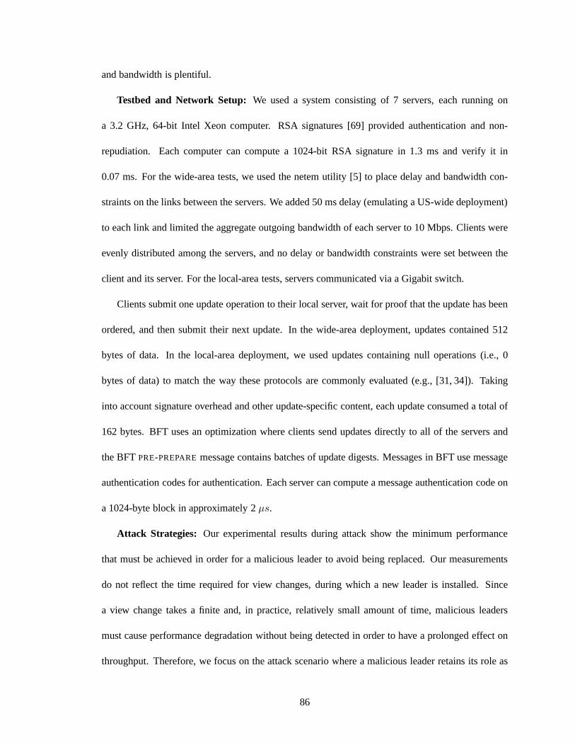
and bandwidth is plentiful.
Testbed and Network Setup: We used a system consisting of 7 servers, each running on
a 3.2 GHz, 64-bit Intel Xeon computer. RSA signatures [69] provided authentication and non-
repudiation. Each computer can compute a 1024-bit RSA signature in 1.3 ms and verify it in
0.07 ms. For the wide-area tests, we used the netem utility [5] to place delay and bandwidth con-
straints on the links between the servers. We added 50 ms delay (emulating a US-wide deployment)
to each link and limited the aggregate outgoing bandwidth ofeach server to 10 Mbps. Clients were
evenly distributed among the servers, and no delay or bandwidth constraints were set between the
client and its server. For the local-area tests, servers communicated via a Gigabit switch.
Clients submit one update operation to their local server, wait for proof that the update has been
ordered, and then submit their next update. In the wide-areadeployment, updates contained 512
bytes of data. In the local-area deployment, we used updatescontaining null operations (i.e., 0
bytes of data) to match the way these protocols are commonly evaluated (e.g., [31, 34]). Taking
into account signature overhead and other update-specific content, each update consumed a total of
162 bytes. BFT uses an optimization where clients send updates directly to all of the servers and
the BFTPRE-PREPAREmessage contains batches of update digests. Messages in BFTuse message
authentication codes for authentication. Each server can compute a message authentication code on
a 1024-byte block in approximately 2µs.
Attack Strategies: Our experimental results during attack show the minimum performance
that must be achieved in order for a malicious leader to avoidbeing replaced. Our measurements
do not reflect the time required for view changes, during which a new leader is installed. Since
a view change takes a finite and, in practice, relatively small amount of time, malicious leaders
must cause performance degradation without being detectedin order to have a prolonged effect on
throughput. Therefore, we focus on the attack scenario where a malicious leader retains its role as
86

leader indefinitely while degrading performance.
To attack Prime, the leader adds as much delay as possible (without being suspected) to the
protocol, and faulty servers force as much reconciliation as possible. As described in Section 4.3, a
malicious leader can add approximately two rounds of delay to the Global Ordering sub-protocol,
plus an aggregation delay. The malicious servers force reconciliation by not sending theirPO-
REQUESTmessages tof of the correct servers. Therefore, allPO-REQUESTmessages originating
from the faulty servers must be sent to thesef correct servers using the Reconciliation sub-protocol
(see Section 4.3.4). Moreover, the malicious servers only acknowledge each other’sPO-REQUEST
messages, forcing the correct servers to send reconciliation messages to them for allPO-REQUEST
messages introduced by correct servers. Thus, allPO-REQUESTmessages undergo a reconciliation
step, which consumes approximately the same outgoing bandwidth as the dissemination of thePO-
REQUESTmessages during the Preordering sub-protocol.
To attack BFT, we use the attack described in Section 3.2. In the wide-area deployment, we
present results for a very aggressive yet possible timeout (300 ms). This yields the most favor-
able performance for BFT under attack. In the local-area network setting, we show results for two
aggressive timeouts (5 ms and 10 ms). We used the original distribution of BFT [1] for all tests.
Unfortunately, the original distribution becomes unstable when run at high throughputs, so we were
unable to get results for BFT in a fault-free execution in theLAN setting. Results using an up-
dated implementation were recently reported in [34] and [47], but we were unable to get the new
implementation to build on our cluster. We base our analysison the assumption that the newer
implementation would obtain similar results on our own cluster.
Performance Results, Wide-Area Deployment:Figure 4.4 shows system throughput, mea-
sured in update operations per second, as a function of the number of clients in the emulated wide-
area deployment. Figure 4.5 shows the corresponding updatelatency, measured at the client. In the
87
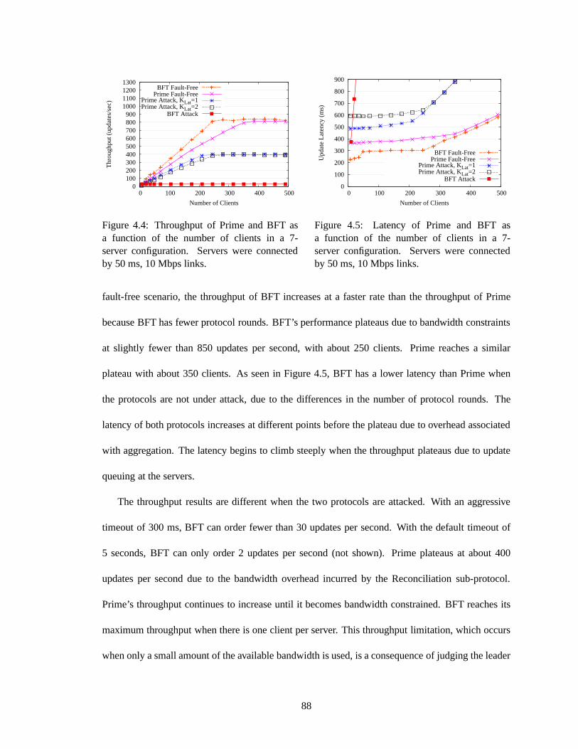
1300 1200 1100 1000 900 800 700 600 500 400 300 200 100
0 0 100 200 300 400 500
Thr
ough
put (
upda
tes/
sec)
Number of Clients
BFT Fault-FreePrime Fault-Free
Prime Attack, KLat=1Prime Attack, KLat=2
BFT Attack
Figure 4.4: Throughput of Prime and BFT asa function of the number of clients in a 7-server configuration. Servers were connectedby 50 ms, 10 Mbps links.
900
800
700
600
500
400
300
200
100
0 0 100 200 300 400 500
Upd
ate
Late
ncy
(ms)
Number of Clients
BFT Fault-FreePrime Fault-Free
Prime Attack, KLat=1Prime Attack, KLat=2
BFT Attack
Figure 4.5: Latency of Prime and BFT asa function of the number of clients in a 7-server configuration. Servers were connectedby 50 ms, 10 Mbps links.
fault-free scenario, the throughput of BFT increases at a faster rate than the throughput of Prime
because BFT has fewer protocol rounds. BFT’s performance plateaus due to bandwidth constraints
at slightly fewer than 850 updates per second, with about 250clients. Prime reaches a similar
plateau with about 350 clients. As seen in Figure 4.5, BFT hasa lower latency than Prime when
the protocols are not under attack, due to the differences inthe number of protocol rounds. The
latency of both protocols increases at different points before the plateau due to overhead associated
with aggregation. The latency begins to climb steeply when the throughput plateaus due to update
queuing at the servers.
The throughput results are different when the two protocolsare attacked. With an aggressive
timeout of 300 ms, BFT can order fewer than 30 updates per second. With the default timeout of
5 seconds, BFT can only order 2 updates per second (not shown). Prime plateaus at about 400
updates per second due to the bandwidth overhead incurred bythe Reconciliation sub-protocol.
Prime’s throughput continues to increase until it becomes bandwidth constrained. BFT reaches its
maximum throughput when there is one client per server. Thisthroughput limitation, which occurs
when only a small amount of the available bandwidth is used, is a consequence of judging the leader
88
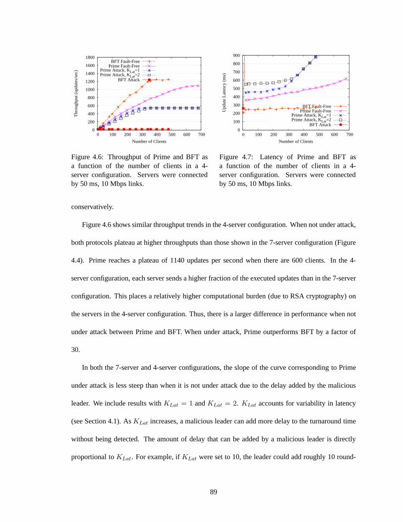
1800
1600
1400
1200
1000
800
600
400
200
0 0 100 200 300 400 500 600 700
Thr
ough
put (
upda
tes/
sec)
Number of Clients
BFT Fault-FreePrime Fault-Free
Prime Attack, KLat=1Prime Attack, KLat=2
BFT Attack
Figure 4.6: Throughput of Prime and BFT asa function of the number of clients in a 4-server configuration. Servers were connectedby 50 ms, 10 Mbps links.
900
800
700
600
500
400
300
200
100
0 0 100 200 300 400 500 600 700
Upd
ate
Late
ncy
(ms)
Number of Clients
BFT Fault-FreePrime Fault-Free
Prime Attack, KLat=1Prime Attack, KLat=2
BFT Attack
Figure 4.7: Latency of Prime and BFT asa function of the number of clients in a 4-server configuration. Servers were connectedby 50 ms, 10 Mbps links.
conservatively.
Figure 4.6 shows similar throughput trends in the 4-server configuration. When not under attack,
both protocols plateau at higher throughputs than those shown in the 7-server configuration (Figure
4.4). Prime reaches a plateau of 1140 updates per second whenthere are 600 clients. In the 4-
server configuration, each server sends a higher fraction ofthe executed updates than in the 7-server
configuration. This places a relatively higher computational burden (due to RSA cryptography) on
the servers in the 4-server configuration. Thus, there is a larger difference in performance when not
under attack between Prime and BFT. When under attack, Primeoutperforms BFT by a factor of
30.
In both the 7-server and 4-server configurations, the slope of the curve corresponding to Prime
under attack is less steep than when it is not under attack dueto the delay added by the malicious
leader. We include results withKLat = 1 andKLat = 2. KLat accounts for variability in latency
(see Section 4.1). AsKLat increases, a malicious leader can add more delay to the turnaround time
without being detected. The amount of delay that can be addedby a malicious leader is directly
proportional toKLat. For example, ifKLat were set to 10, the leader could add roughly 10 round-
89
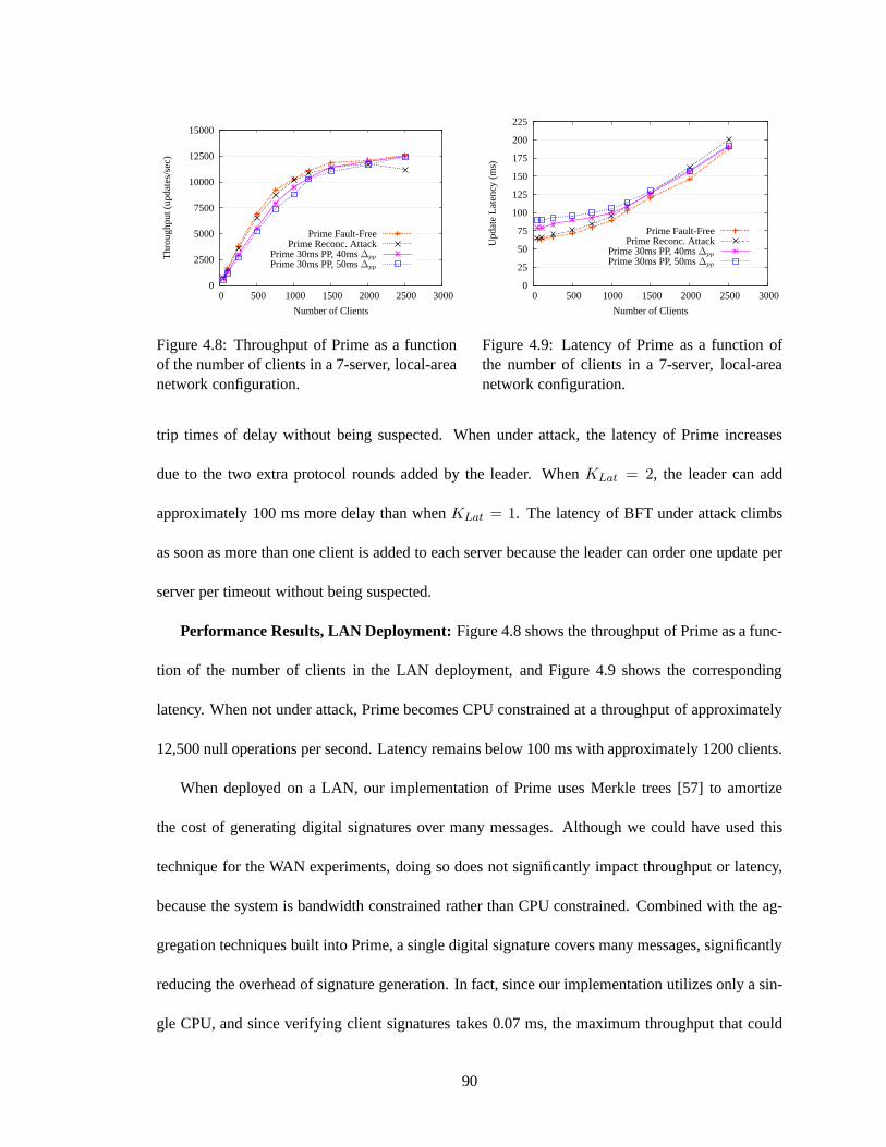
15000
12500
10000
7500
5000
2500
0 0 500 1000 1500 2000 2500 3000
Thr
ough
put (
upda
tes/
sec)
Number of Clients
Prime Fault-FreePrime Reconc. Attack
Prime 30ms PP, 40ms∆pp
Prime 30ms PP, 50ms∆pp
Figure 4.8: Throughput of Prime as a functionof the number of clients in a 7-server, local-areanetwork configuration.
225
200
175
150
125
100
75
50
25
0 0 500 1000 1500 2000 2500 3000
Upd
ate
Late
ncy
(ms)
Number of Clients
Prime Fault-FreePrime Reconc. Attack
Prime 30ms PP, 40ms∆pp
Prime 30ms PP, 50ms∆pp
Figure 4.9: Latency of Prime as a function ofthe number of clients in a 7-server, local-areanetwork configuration.
trip times of delay without being suspected. When under attack, the latency of Prime increases
due to the two extra protocol rounds added by the leader. WhenKLat = 2, the leader can add
approximately 100 ms more delay than whenKLat = 1. The latency of BFT under attack climbs
as soon as more than one client is added to each server becausethe leader can order one update per
server per timeout without being suspected.
Performance Results, LAN Deployment:Figure 4.8 shows the throughput of Prime as a func-
tion of the number of clients in the LAN deployment, and Figure 4.9 shows the corresponding
latency. When not under attack, Prime becomes CPU constrained at a throughput of approximately
12,500 null operations per second. Latency remains below 100 ms with approximately 1200 clients.
When deployed on a LAN, our implementation of Prime uses Merkle trees [57] to amortize
the cost of generating digital signatures over many messages. Although we could have used this
technique for the WAN experiments, doing so does not significantly impact throughput or latency,
because the system is bandwidth constrained rather than CPUconstrained. Combined with the ag-
gregation techniques built into Prime, a single digital signature covers many messages, significantly
reducing the overhead of signature generation. In fact, since our implementation utilizes only a sin-
gle CPU, and since verifying client signatures takes 0.07 ms, the maximum throughput that could
90

be achieved is just over 14,000 updates per second (if the only operation performed were verify-
ing client signatures). This implies that (1) signature aggregation is effective in improving peak
throughput and (2) the peak throughput of Prime could be significantly improved by offloading
cryptographic operations (specifically, signature verification) to a second processor (or to multiple
cores), as is done in the recent implementation of the Aardvark protocol [34].
As Figure 4.8 demonstrates, the performance of Prime under attack is quite different on a LAN
compared to a WAN. We separated the delay attacks from the reconciliation attacks so their effects
could be seen more clearly. Note that the reconciliation attack, which degraded throughput by
approximately a factor of 2 in a wide-area environment, has very little impact on throughput on a
LAN because the erasure encoding operations are inexpensive and bandwidth is plentiful.
In our implementation, the leader is expected to send aPRE-PREPAREevery 30 ms. On a local-
area network, the duration of this aggregation delay dominates any variability in network latency.
Recall that in Suspect-Leader, a non-leader server computes the maximum turnaround time ast =
rtt ∗ KLat + ∆pp, wherertt is the measured round-trip time and∆pp is a value greater than the
maximum time it might take a correct server to send aPRE-PREPARE (see Algorithm 3, line 27).
We ran Prime with two different values of∆pp: 40 ms and 50 ms. A malicious leader only includes
a SUMMARY-MATRIX in its currentPRE-PREPARE if it determines that including theSUMMARY-
MATRIX in the nextPRE-PREPARE (sent 30 ms in the future) would potentially cause the leader
to be suspected, given the value of∆pp. Figures 4.8 and 4.9 show that the leader’s attempts to
add delay only increase latency slightly, by about 15 ms and 25 ms, respectively. As expected, the
attacks do not impact peak throughput.
As noted above, the implementation of BFT that we tested doesnot work well when run at high
speeds; the servers begin to lose messages due to a lack of sufficient flow control, and some of the
servers crash. Therefore, we were unable to generate results for fault-free executions. Recently
91
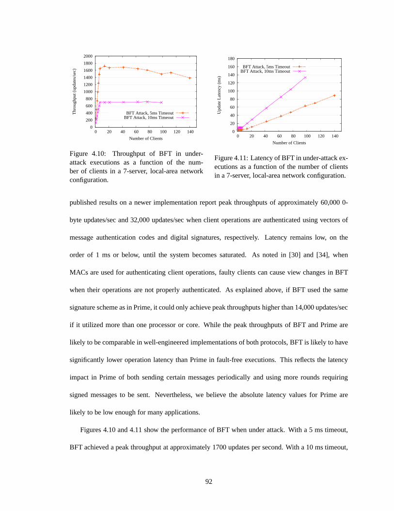
2000
1800
1600
1400
1200
1000
800
600
400
200
0 0 20 40 60 80 100 120 140
Thr
ough
put (
upda
tes/
sec)
Number of Clients
BFT Attack, 5ms TimeoutBFT Attack, 10ms Timeout
Figure 4.10: Throughput of BFT in under-attack executions as a function of the num-ber of clients in a 7-server, local-area networkconfiguration.
180
160
140
120
100
80
60
40
20
0 0 20 40 60 80 100 120 140
Upd
ate
Late
ncy
(ms)
Number of Clients
BFT Attack, 5ms TimeoutBFT Attack, 10ms Timeout
Figure 4.11: Latency of BFT in under-attack ex-ecutions as a function of the number of clientsin a 7-server, local-area network configuration.
published results on a newer implementation report peak throughputs of approximately 60,000 0-
byte updates/sec and 32,000 updates/sec when client operations are authenticated using vectors of
message authentication codes and digital signatures, respectively. Latency remains low, on the
order of 1 ms or below, until the system becomes saturated. Asnoted in [30] and [34], when
MACs are used for authenticating client operations, faultyclients can cause view changes in BFT
when their operations are not properly authenticated. As explained above, if BFT used the same
signature scheme as in Prime, it could only achieve peak throughputs higher than 14,000 updates/sec
if it utilized more than one processor or core. While the peakthroughputs of BFT and Prime are
likely to be comparable in well-engineered implementations of both protocols, BFT is likely to have
significantly lower operation latency than Prime in fault-free executions. This reflects the latency
impact in Prime of both sending certain messages periodically and using more rounds requiring
signed messages to be sent. Nevertheless, we believe the absolute latency values for Prime are
likely to be low enough for many applications.
Figures 4.10 and 4.11 show the performance of BFT when under attack. With a 5 ms timeout,
BFT achieved a peak throughput at approximately 1700 updates per second. With a 10 ms timeout,
92
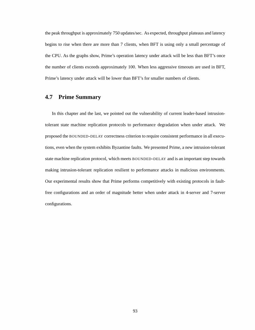
the peak throughput is approximately 750 updates/sec. As expected, throughput plateaus and latency
begins to rise when there are more than 7 clients, when BFT is using only a small percentage of
the CPU. As the graphs show, Prime’s operation latency underattack will be less than BFT’s once
the number of clients exceeds approximately 100. When less aggressive timeouts are used in BFT,
Prime’s latency under attack will be lower than BFT’s for smaller numbers of clients.
4.7 Prime Summary
In this chapter and the last, we pointed out the vulnerability of current leader-based intrusion-
tolerant state machine replication protocols to performance degradation when under attack. We
proposed theBOUNDED-DELAY correctness criterion to require consistent performance in all execu-
tions, even when the system exhibits Byzantine faults. We presented Prime, a new intrusion-tolerant
state machine replication protocol, which meetsBOUNDED-DELAY and is an important step towards
making intrusion-tolerant replication resilient to performance attacks in malicious environments.
Our experimental results show that Prime performs competitively with existing protocols in fault-
free configurations and an order of magnitude better when under attack in 4-server and 7-server
configurations.
93
Chapter 5
An Attack-Resilient Architecture for
Large-Scale Intrusion-Tolerant
Replication
This chapter presents an attack-resilient architecture for large-scale intrusion-tolerant replication
over wide-area networks. It is joint work with Yair Amir, Brian Coan, and John Lane. Some of the
ideas were developed during the author’s visit to the Navigators Distributed Systems Research Team
at the University of Lisboa, Portugal.
The material in this chapter unifies our work on hierarchicalintrusion-tolerant replication (i.e.,
Steward [18, 19] and the customizable replication architecture [16]) with our work on Prime. The
end result is the first large-scale intrusion-tolerant state machine replication system capable of mak-
ing meaningful performance guarantees even when some of themachines are compromised.
Our system builds on our work on the customizable replication architecture presented in [16],
using the same basic approach to scaling. It uses a two-levelhierarchy. Each site runs a local state
machine replication protocol and is converted into alogical machinethat acts as a single participant
94
in a wide-area state machine replication protocol that runsamong the logical machines. The local
protocols are cleanly separated from the wide-area protocol. The benefit of this clean separation is
that the safety of the hierarchical system as a whole followsdirectly from the safety properties of
the flat protocols running in each level of the hierarchy, making the system easier to reason about.
Indeed, one can substitute in a different local state machine replication protocol without impacting
the safety of the system.
This free substitution property does not necessarily hold with respect to performance under
attack. The performance characteristics of the local statemachine replication protocol running
within a site determine the timing properties of the resulting logical machine. Given that one has
selected to deploy a particular wide-area state machine replication protocol,P , not all local state
machine replication protocols will be able to provide the timing and performance properties thatP
needs to make a performance guarantee (or, potentially, to even provide liveness) when the system is
under attack. For example, ifP requires certain messages to be delivered within a bounded amount
of time, then using a local protocol that only guarantees that messages will be eventually ordered
will not provide the necessary degree of timeliness. Put another way, it is important to deploy local
protocols that, when the network is sufficiently stable, provide the “right kind” of performance with
respect to the needs of the wide-area protocol.
Assuming the right set of local and global replication protocols can be chosen, the main technical
challenge that must be overcome in building our attack-resilient architecture is to provide efficient
and attack-resilient communication between the wide-areasites. Since the physical machines in
each site run a local state machine replication protocol, they process the same global protocol events
in the same order. Thus, when the logical machine generates amessage to be sent in the global
protocol, any of the physical machines within the site is capable of sending it on the wide area. We
must define alogical link protocol to determine which local physical machine or machines send,
95
what they send, and to which remote physical machine or machines they send it. We present three
logical link protocols, each with different performance characteristics during fault-free executions
and in the face of Byzantine faults.
Our attack-resilient architecture relies solely on the correctness of the servers for safety. Specif-
ically, the system maintains safety as long as enough correct servers in enough sites remain correct
(we define this notion formally in Section 5.1). At the same time, the system can optionally be
configured to make use of two types of additional components to improve performance. The first
is a broadcast Ethernet hub, and the second is a simple devicecapable of counting and sending
messages. In our system, the failure (Byzantine or benign) of these additional components can
impact performance or liveness negatively, but any number of the additional components can be
compromised without violating safety.
Other systems take a different approach, adopting a hybrid failure model in which additional
components are assumed not to be compromised or are assumed to always exhibit strong timing
guarantees; other components of the system can be Byzantineand may offer weaker timing guar-
antees. The benefit of making such a strong assumption about the additional components is that
replication systems that do so (e.g., [36, 55, 78]) tend to besimpler and can achieve higher perfor-
mance than those that do not. It is also easier to scale them because the core agreement protocol
(run among the additional components) can be more efficient,as it assumes a weaker fault model.
The trade-off is that such systems can typically lose safetywhen the assumptions made about even
a single additional component are violated.
To distinguish between the two patterns of use for additional components, we refer to compo-
nents whose compromise cannot lead to safety violations asdependable components, and compo-
nents which are assumed not to be compromised astrusted components. Trusted components are
sometimes referred to aswormholes[81]. Both dependable and trusted components should be care-
96
fully developed, and their correctness should be validatedto the extent possible. They may also
be deployed using techniques that make it hard for an attacker to alter or bypass them, possibly
including special hardware. The design, verification, and deployment of these components can be
an expensive process whose cost grows rapidly as the complexity of the component increases. For
this reason, these types of components typically do a very small but useful job.
In the remainder of this chapter, we first present the system model assumed by the attack-
resilient architecture. The model is a straightforward extension of the one used by Prime (see
Section 4.1). Section 5.2 provides background on the hierarchical, customizable architecture on
which the new architecture is based. Section 5.3 describes our approach to making the pieces of the
customizable architecture attack resilient and highlights the key design challenges that arise when
trying to integrate the pieces into a unified system. Section5.4 addresses the important problem of
how to achieve efficient and attack-resilient inter-site communication, describing three new logical
link protocols. Section 5.5 presents the complete attack-resilient architecture and discusses several
practical issues related to its implementation. Section 5.6 specifies the safety, liveness, and perfor-
mance properties of the system. Section 5.7 evaluates the performance of a prototype implemen-
tation of the system, focusing on the implications of deploying the different logical link protocols.
Finally, Section 5.8 concludes the chapter by summarizing the contributions of the attack-resilient
architecture.
5.1 System Model
We consider a system withN sites, denotedS1 throughSN , distributed across a wide-area
network. Each site,Si, has3fi + 1 servers. IfSi is a correct site, then no more thanfi of its servers
are faulty; ifSi is a Byzantine site, then any number of its servers may be faulty, modeling situations
where entire sites can be compromised. We denoteF as an upper bound on the number of Byzantine
97
sites and assume that the total number of sites is equal to3F +1. For simplicity, we assume in what
follows that all sites tolerate the same number of faults,f , and have the same number of servers,
3f + 1. The solutions presented in this chapter can be extended to the more general setting where
sites may have different numbers of servers.
We assume an asynchronous network. The safety properties ofthe attack-resilient architecture
hold in all executions in whichF or fewer sites are Byzantine. The liveness and performance
properties of the system are only guaranteed to hold in subsets of the executions that satisfy certain
constraints on message delay.
We allow each correct processor to designate the traffic class of each message that it sends as
one of: LOCAL-TIMELY , LOCAL-BOUNDED, GLOBAL-TIMELY , and GLOBAL-BOUNDED. Mes-
sages sent in traffic classes with theLOCAL prefix are sent between servers in the same site, while
messages sent in traffic classes with theGLOBAL prefix are sent between servers in different sites.
Note that all four of these traffic classes are used in the lower level of the hierarchy (i.e., among
physical machines).
For some of our analysis, we will also be referring to two additional virtual traffic classes:
VIRTUAL -TIMELY and VIRTUAL -BOUNDED. Intuitively, virtual traffic classes carry (inter-site)
messages between logical machines. However, the virtual traffic classes are abstract—they are
concepts supported by the protocols running in the lower level of the hierarchy. Thus, although we
say that a logical machine “sends” wide-area messages and designates them as eitherVIRTUAL -
TIMELY or VIRTUAL -BOUNDED, wide-area messages are physically sent on the network by one or
more physical machines, and the messages are physically carried in either theGLOBAL-TIMELY or
GLOBAL-BOUNDED traffic class. As described in Section 5.6, the timing properties of the virtual
traffic classes depend on the timing properties of all components of the system that can delay the
(conceptual) sending or receiving of a message by a logical machine. We will be interested in ana-
98
lyzing the timing properties of the virtual traffic classes in order to prove that the system as a whole
meets certain performance and liveness properties.
All messages sent between servers, and between clients and servers, are digitally signed. We
assume that digital signatures are unforgeable without knowing a processor’s private key. We use
an (f + 1, 3f + 1) threshold digital signature scheme (see Section 2.1) for generating threshold
signatures on wide-area messages. Each site has a public key, and each server within a site is given
a secret share that can be used to generate partial signatures. We assume threshold signatures are
unforgeable without knowing the secret shares off + 1 servers within a site. We also employ a
collision-resistant cryptographic hash function for computing message digests.
A client submits an operation (query or update) to the systemby sending it to one or more
servers, which may be in the client’s local site or in a remotesite. Operations submitted to the
local site are sent in theLOCAL-BOUNDED traffic class, while operations submitted to remote sites
are sent in theGLOBAL-BOUNDED traffic class. Each client operation is signed. As in the model
assumed by Prime, there exists a function,Client, known to all processors, that maps each operation
to a single client, and an operation,o, is valid if it was signed by the client with identifierClient(o).
Correct clients wait for the reply to their current operation before submitting the next operation.
Textually identical operations are considered multiple instances of the same operation. Each server
produces a sequence of operations,{o1, o2, . . .}, as its output. The safety, liveness, and performance
properties of the system depend on which state machine replication protocols are deployed in each
level of the hierarchy, so we defer a discussion of these properties until Section 5.6.
In Section 5.4 we present three logical link protocols for inter-site communication, two of which
rely on dependable components. In the hub-based logical link (see Section 5.4.2), each site is
equipped with a dependable broadcast hub, through which incoming and outgoing wide-area traffic
passes. In the dependable forwarder-based logical link (see Section 5.4.3), each site is equipped
99

with a dependable forwarding device that sends and receivesinter-site messages on behalf of the
site. Each dependable forwarder shares a distinct symmetric key with each other dependable for-
warder and with each local server for computing message authentication codes. The failure (crash
or compromise) of the dependable components can impact performance and liveness but cannot lead
to safety violations.
5.2 Background: A Customizable Replication Architecture
Our attack-resilient architecture builds on our previous work on wide-area intrusion-tolerant
replication [16,19], which demonstrated the performance benefit of using hierarchy to reduce wide-
area message complexity. The new architecture can be thought of as hardening the customizable
architecture presented in [16] against performance attacks. This section provides background on the
customizable architecture.
The physical machines in each site cooperate to implement alogical machinethat is capable
of processing global protocol events (i.e., message reception and timeout events) just as a physical
machine would. Each logical machine acts as a single participant in a global, wide-area replication
protocol that runs among the logical machines. Intuitively, a logical machine executes the code that
would implement a single server in the global replication protocol if the protocol were run in a flat
(i.e., non-hierarchical) architecture.
In order to support the abstraction of a logical machine, thephysical machines in each site
run a local state machine replication protocol to totally order any event that would change the
state of the logical machine. Specifically, the local state machine replication protocol orders events
corresponding to either the reception of a global protocol message or the firing of a global protocol
timeout by the logical machine. A physical machine processes a global protocol event when it
locally executesit, which occurs after the machine learns of the event’s local ordering and after it
100
has locally executed all previous events in the local order.Since all physical machines in the site
locally execute the same global events in the same order, thelogical machine processes a single
stream of global protocol events.
When the logical machine processes an event, it may generatea global protocol message that
should be sent on the wide area. For example, the logical machine might generate an acknowl-
edgement every time it processes a particular message, or itmight generate a status message when
it processes a timeout event (analogous to the firing of a timeout on a single physical machine).
Before the message can be sent on the wide area, the physical machines implementing the logical
machine run a protocol to generate a threshold signature on the message. The threshold signature
proves that at least one correct physical machine in the siteassents to the content of the associated
message, preventing faulty machines in correct sites from sending spurious messages that purport
to be from the logical machine. Once a message is threshold signed, it can be sent to its destination
sites according to the communication patterns of the globalreplication protocol; we say that the
message is sent over alogical link that exists between each pair of sites. Of course, the logical link
must be implemented by actions taken by physical machines inthe lower level of the hierarchy,
involving real network interfaces. These actions are the topic of Section 5.4.
5.3 Building an Attack-Resilient Architecture
In this section we describe our approach to making the customizable architecture presented in
Section 5.2 attack resilient. There are four pieces of the customizable architecture: the global state
machine replication protocol, the local state machine replication protocol, the threshold signature
protocol, and the logical links that connect the logical machines. It is clear that in order for the
system as a whole to perform well under attack, each piece must perform well under attack. Section
5.3.1 describes how each piece can be hardened to resist performance failures. However, converting
101
the customizable architecture into a unified, attack-resilient system is not as simple as making each
piece perform well in isolation. Section 5.3.2 describes two key design dependencies that exist
among the pieces of the architecture. These dependencies impact which protocols can be deployed
together and what type of performance each protocol must exhibit. Section 5.3.3 discusses which
state machine replication protocols we chose to deploy in our implementation.
5.3.1 Making Each Piece Attack Resilient
In order to resist performance failures in the global and local state machine replication protocols,
the system should deploy, in each level of the hierarchy, a flat protocol that provides a meaningful
performance guarantee when some of the servers are Byzantine. We know of two flat, attack-
resilient state machine replication protocols that do not rely on trusted components: Prime and
Aardvark [34]. As described in Chapter 4, Prime bounds the latency of operations submitted to, and
subsequently introduced by, correct participants. Aardvark guarantees that over sufficiently long
periods, system throughput will be within a constant factorof what it would be with only correct
participants, provided there are enough operations to saturate the system.
In environments where the risk of total site compromise is small, the global state machine repli-
cation protocol can be benign fault tolerant rather than Byzantine fault tolerant and attack resilient;
this was the approach taken in Steward [18, 19]. This resultsin a more efficient protocol that re-
quires only two wide-area crossings, and it also reduces thenumber of required local orderings.
Note that the logical link protocol must still be made attackresilient in order to avoid performance
degradation, even when a benign fault-tolerant global replication protocol is used.
To resist performance failures in the threshold signature protocol, we use a protocol in which
partial signatures areverifiable, meaning they carry proofs of correctness that can be used todetect
(and subsequently blacklist) faulty servers that submit invalid partial signatures. This allows sub-
102
sequent messages from blacklisted servers to be ignored, preventing faulty servers from repeatedly
disrupting threshold signature generation. A representative example of such a scheme (and the one
used in our implementation) is Shoup’s threshold RSA signature scheme [76].
Finally, making the logical link protocol attack resilientis critical to achieving high performance
under attack. We discuss this topic in detail in Section 5.4.
5.3.2 Design Dependencies Among the Pieces
The choice of which global state machine replication protocol is deployed imposes certain per-
formance requirements on each of the other pieces of the architecture. Specifically, the other pieces
must exhibit performance characteristics that allow the timing assumptions of the global protocol to
be met. The global protocol makes timing assumptions about the logical machine processing time
and the inter-site message delay. We discuss each of these inturn.
Logical Machine Processing Time:The logical machine processing time is directly related
to the performance of the local state machine replication protocol. Just as individual servers are
expected to process events within some delay in a flat architecture (when the system is stable),
logical machines are expected to process events within somedelay in the hierarchical architecture.
Intuitively, given a global replication protocol,P , the processing time of a logical machine running
P in the hierarchical architecture must meet the same predictability requirements as those met by a
single physical machine runningP in a flat architecture.
Inter-Site Message Delay: In a flat architecture, the message delay between two serversis
the sum of the delay from the network itself and the processing time of the receiving server. In
the hierarchical architecture, the message delay between two logical machines is the sum of four
component delays: the delay from the threshold signature protocol, the delay from the logical link
protocol, the delay from the network itself, and the processing time of the logical machine. Thus,
103
besides requiring a certain degree of network stability, the hierarchical architecture requires the
performance of the threshold signature, logical link, and local state machine replication protocols to
be predictable enough to support the timing assumptions of the traffic classes of the global protocol.
5.3.3 Choosing the State Machine Replication Protocols
We now discuss which state machine replication protocols wechose to deploy in our implemen-
tation, in light of the dependencies described above. As noted, the threshold signature and logical
link protocols must also exhibit specific timing properties. We defer a discussion of this issue until
Section 5.6, where we formally define the timing requirements needed for the system’s liveness and
performance properties to hold.
While either Prime or Aardvark can be used as the global statemachine replication protocol,
we chose to use Prime in our implementation. Each participant in Prime disseminates operations
from its own clients, and thus the protocol distributes the task of disseminating operations across all
participants. In contrast, Aardvark requires the primary to disseminate all client operations. When
the distribution of operations submitted to each site is relatively balanced, this allows Prime to
achieve a higher peak throughput than Aardvark: while Aardvark’s throughput is bandwidth limited
to the number of operations that can be disseminated by the primary per second, Prime can use
more aggregate bandwidth for operation dissemination before becoming bandwidth limited. This
is important because bandwidth is likely to be the performance bottleneck in wide-area replication
systems. On the other hand, we note that Aardvark may be a better fit than Prime in environments
with stringent average latency requirements where the offered load is relatively light, since Aardvark
has fewer protocol rounds and requires fewer wide-area crossings.
Having selected Prime as our global protocol, the local state machine replication protocol must
be chosen such that the resulting logical machine has the performance and timing properties needed
104
to meet Prime’s timing assumptions. In a flat architecture, the minimum level of synchrony that
Prime requires from servers in order to meetBOUNDED-DELAY is that they be able to process
events within a bounded time. Bounded processing time is needed for two reasons. First, to bound
the latency of a client operation, servers must be able to process client operations in bounded time.
Second, bounded processing time enables the timing requirements of Prime’s traffic classes to be
met.1 The same reasoning can be applied to the hierarchical architecture, and thus the local protocol
must be able to bound the time required to locally order a global protocol event.
The ability to bound the local ordering time is precisely theproperty that a Prime-based logical
machine provides when (1) all events requiring bounded processing time are introduced for local
ordering by at least one correct server, (2) the load offeredto the logical machine does not exceed the
maximum throughput of the local instance of Prime that implements the logical machine, and (3) the
network is stable. In our attack-resilient architecture, the first condition is guaranteed by the way in
which servers introduce events for local ordering. We explain why the second and third conditions
can be made to hold in Section 5.6. Since Prime can provide therequired degree of timeliness even
when some of the servers are Byzantine, we chose to use it as our local state machine replication
protocol.
It is interesting to note that despite the fact that Aardvarkmakes a strong throughput guarantee
when the system is under attack, the type of guarantee that itmakes does not support the timing
properties of the global instance of Prime. Aardvark guarantees a meaningful throughput over
sufficiently long periods of time. However, it does not guarantee thatindividual operationsare
ordered in a bounded time. In fact, operations submitted during the grace period that begins a view
with a faulty primary can take several seconds to be ordered,since the system may need to rotate
through several faulty primaries before finding a correct one. The result is that even though the
1As explained in Section 5.6, meeting the timing requirements of theVIRTUAL -TIMELY traffic class (analogous to theTIMELY traffic class in a flat system) also involves choosing a suitable latency variability constant.
105
average logical machine processing time of an Aardvark-based logical machine is likely to be low,
Aardvark does not support bounded logical machine processing time. Note that the local ordering of
individual operations may also be delayed in Prime when the local leader is faulty. However, the key
difference is that Prime will eventually settle on leaders that do not cause delay or introduce only a
small bounded delay, while Aardvark will perpetually be vulnerable to periods in which latency is
temporarily increased, potentially by many seconds.
5.4 Attack-Resilient Logical Links
The physical machines within a site construct and thresholdsign global protocol messages after
locally executing global protocol events. This raises the question of how to pass the threshold-signed
message from the sending logical machine to a destination logical machine. Each correct server that
generates the threshold-signed message is capable of passing it to any server in the destination site.
We must define alogical link protocolto dictate which local server or servers send, what they send,
and to which server or servers they send it.
The challenge in designing a logical link protocol is to simultaneously achieve attack resilience
and efficiency. Existing approaches used in logical machinearchitectures (e.g., [16,27,60]) achieve
one but not the other. For example, iff + 1 physical machines in the sending site each transmit the
threshold-signed message tof + 1 physical machines in the receiving site, then at least one correct
machine in the receiving site is guaranteed to receive a copyof the message—at least one of the
senders is correct, and at least one of that correct machine’s receivers is correct. Such a logical link
is attack resilient, because faulty machines cannot prevent a message from being successfully trans-
mitted in a timely manner, but the protocol pays a high cost inwide-area bandwidth, transmitting
each message up to(f + 1)2 times.
Due to the overhead of sending messages redundantly, our previous work [16] adopted a dif-
106
ferent approach, called the BLink protocol, in which the physical machines in each site elect one
machine to act as asite forwarder, charged with the responsibility of sending messages on behalf
of the site. The physical machines also choose the identifierof the machine in the receiving site
with which the forwarder should communicate. The non-forwarders use timeouts, coupled with
acknowledgements from the receiving site, to monitor the forwarder and ensure that it passes mes-
sages at some minimal rate. If the current (forwarder, receiver) pair is deemed faulty, a new pair is
elected.
BLink is efficient but not attack resilient: the forwarder and receiver can collude to avoid being
replaced as long as they ensure that the forwarder collects acknowledgements just before the timeout
expires, resulting in much lower throughput and higher latency on the logical link than correct ma-
chines would provide. Using a more aggressive approach to monitoring (by attempting to determine
how fast the forwarder should be sending messages) requiresadditional timing and bandwidth as-
sumptions which may be difficult to realize in practice. Notethat BLink’s performance degrades in
the presence of Byzantine faults because the protocol was built to ensure liveness, not to achieve at-
tack resilience. Liveness requires the logical link to makeminimal progress—and, for this purpose,
a coarse-grained timeout works well. BLink obtains high fault-free performance by depending on
the site forwarder to pass messages, but giving a single machine this power is precisely what makes
the protocol vulnerable to performance degradation by a malicious forwarder.
In the remainder of this section, we present and compare three new logical link protocols. The
design of the three protocols brings to light a trade-off between the strength of one’s assumptions
and the resulting performance that one can achieve, with each protocol representing a different point
in the design space. All three protocols share the same goals:
Attack Resilience. The logical link protocol should limit or remove the power ofthe adversary to
cause performance degradation, without unduly sacrificingfault-free performance.
107

Modularity. It should be possible to substitute one logical link protocol for another without impact-
ing the correctness of the global replication protocol, allowing deployment flexibility based
on what system components one wishes to depend on. Conversely, the logical link protocol
should be generic enough so that it can be used with differentwide-area replication protocols.
Simplicity. Given the inherent complexity of intrusion-tolerant replication protocols, the logical
link protocols should be easy to reason about and straightforward to implement.
Section 5.4.1 presents a logical link that does not require dependable components and that era-
sure encodes outgoing messages to reduce the cost of sendingredundantly. Section 5.4.2 shows
how augmenting the erasure encoding approach with a broadcast hub can improve performance in
fault-free and under-attack executions. Section 5.4.3 describes how relying on a dependable for-
warder can yield an optimal use of wide-area bandwidth without making it easier for an attacker
to cause inconsistency. Section 5.4.4 describes the commonfeatures of the logical link protocols
and discusses some general principles for intrusion-tolerant system design that can be gleaned from
them.
5.4.1 Erasure Encoding-Based Logical Link
We first present a simple, software-based logical link protocol. In what follows, we consider
how a sending site,S, passes a threshold-signed message to a receiving site,R. We definevirtual
link i as the ordered pair(si, ri), wheresi andri refer to the physical machines with identifieri
in sitesS andR, respectively. We callsi andri peers. Communication over the logical link takes
place between peers using the set of3f + 1 virtual links.
Instead of having each physical machine inS transmit the full threshold-signed message to its
peer inR, the physical machines first encode the message using a Maximum Distance Separable
erasure-resilient coding scheme (see Section 2.2). Specifically, lettingt be the total number of bits
108
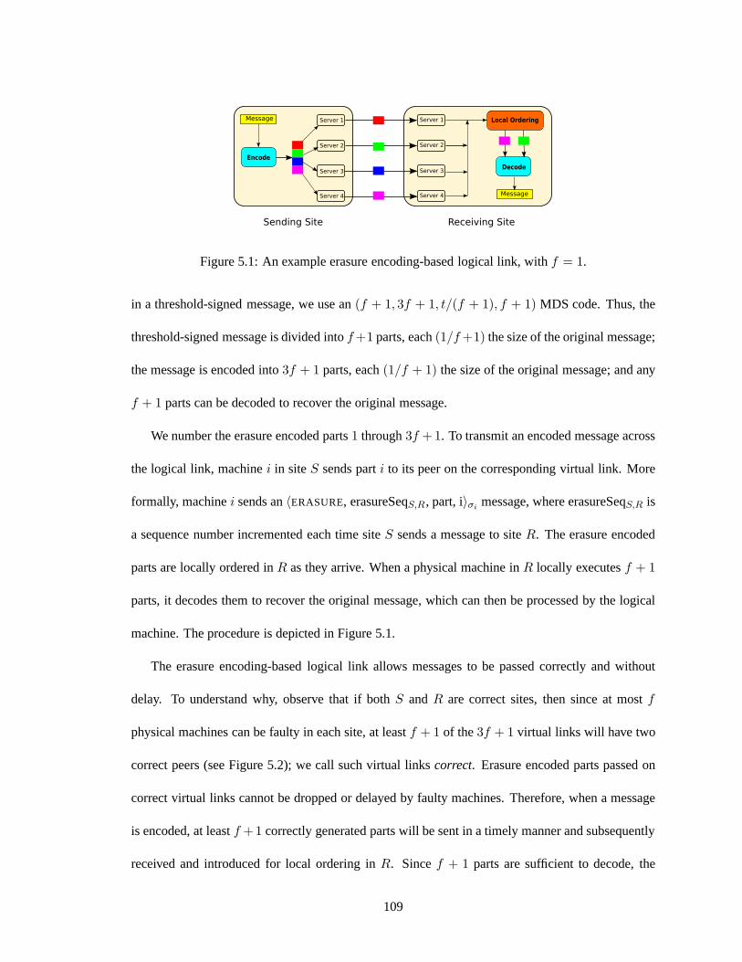
Figure 5.1: An example erasure encoding-based logical link, with f = 1.
in a threshold-signed message, we use an(f + 1, 3f + 1, t/(f + 1), f + 1) MDS code. Thus, the
threshold-signed message is divided intof +1 parts, each(1/f +1) the size of the original message;
the message is encoded into3f + 1 parts, each(1/f + 1) the size of the original message; and any
f + 1 parts can be decoded to recover the original message.
We number the erasure encoded parts1 through3f +1. To transmit an encoded message across
the logical link, machinei in siteS sends parti to its peer on the corresponding virtual link. More
formally, machinei sends an〈ERASURE, erasureSeqS,R, part, i〉σimessage, where erasureSeqS,R is
a sequence number incremented each time siteS sends a message to siteR. The erasure encoded
parts are locally ordered inR as they arrive. When a physical machine inR locally executesf + 1
parts, it decodes them to recover the original message, which can then be processed by the logical
machine. The procedure is depicted in Figure 5.1.
The erasure encoding-based logical link allows messages tobe passed correctly and without
delay. To understand why, observe that if bothS and R are correct sites, then since at mostf
physical machines can be faulty in each site, at leastf + 1 of the3f + 1 virtual links will have two
correct peers (see Figure 5.2); we call such virtual linkscorrect. Erasure encoded parts passed on
correct virtual links cannot be dropped or delayed by faultymachines. Therefore, when a message
is encoded, at leastf +1 correctly generated parts will be sent in a timely manner andsubsequently
received and introduced for local ordering inR. Sincef + 1 parts are sufficient to decode, the
109

Figure 5.2: Intuition behind the correctness of the erasureencoding-based logical link. In thisexample,f = 2. The adversary can block at mostf virtual links by corrupting servers in thesending site andf virtual links by corrupting servers in the receiving site.
physical machines inR will be able to decode successfully.
As noted above, each erasure encoded part is1/(f + 1) the size of the original message. Since
each of the3f + 1 servers inS sends a part, the aggregate bandwidth overhead of the logical link
is approximately(3f + 1)(1/f + 1), which approaches 3 asf increases to infinity. The bandwidth
overhead is slightly greater than this because anERASUREmessage containing parti carries a digital
signature from serveri in siteS. Therefore, in the worst case,3f+1 signatures must be sent for each
original message, compared to one if a single server were sending on behalf of the site. In practice,
the signature overhead can be amortized over several outgoing messages by packing erasure encoded
parts for several messages into a single digitally-signed physical message.
The erasure encoding approach also has a higher computational cost than an approach in which
a single server sends messages on behalf of the site. The receiving site locally orders the incoming
parts as they arrive, meaning that the reception of a messageby the logical machine requires the local
ordering of up to3f + 1 events. Section 5.5 describes implementation optimizations that can be
used to mitigate this computational overhead. When these optimizations are used, the performance
of the system becomes bandwidth limited, so it is desirable to pay the cost of additional computation
in order to use wide-area bandwidth more efficiently.
110

Blacklisting Servers that Send Invalid Parts
The preceding discussion assumed that erasure encoded parts were generated correctly. How-
ever, as in Prime’s Reconciliation sub-protocol (see Section 4.3.4), faulty servers may generate
invalid parts in an attempt to disrupt the decoding process.Unlike partial signatures, erasure en-
coded parts are not individually verifiable: they do not carry proofs that they were created correctly.
If a server attempts to decode a message usingf + 1 parts but obtains an invalid message (i.e., one
whose threshold signature does not verify correctly), it cannot, without further information, deter-
mine which (if any) of the parts are invalid. There are two possible cases: (1) one or more of the
parts are invalid, or (2) all of the parts are valid, but the site that sent the message is faulty and
encoded a message with an invalid threshold signature. Evenif the server waits for additional parts
to arrive, there is no efficient way for it to find a set off + 1 valid parts out of a larger set. With-
out a mechanism for determining which parts are faulty, malicious servers can repeatedly cause the
correct servers to expend computational resources (i.e., by exhaustive search) to determine which
parts should be used in the decoding. If the site that sent themessage is indeed faulty, then no
combination of parts may decode to a valid message.2
To overcome these difficulties, we augment the basic erasureencoding scheme with a black-
listing mechanism that can be used to prevent faulty serversfrom repeatedly causing the message
decoding to fail by submitting invalid parts. We employ bothsite-level and server-level blacklists.
When a site is blacklisted, subsequent messages from all servers in that site are ignored. When a
server is blacklisted, only messages originating from thatserver are ignored; messages from non-
blacklisted servers in the same site continue to be processed.
In the description that follows, we consider a message beingsent between two sites,S andR,
2The fact that no combination of parts may decode to a valid message makes the problem more severe than in Prime’sReconciliation sub-protocol, where onlyPO-REQUESTmessages with valid digital signatures were encoded.
111

whereS sends an erasure encoded message toR that results in a failed decoding. The blacklisting
protocol guarantees that:
• If both S andR are correct, then the correct servers inR will blacklist a faulty server in
S after the server generates just one invalid erasure encodedpart; from then on, that faulty
server will not be able to disrupt the decoding at any correctserver inR.
• If S is faulty andR is correct, then each faulty server inS can disrupt the decoding at most
once in each receiving siteR before it is blacklisted by the correct servers inR. If S fails to
take part in the blacklisting protocol, messages from all ofits servers will be ignored by the
correct servers inR, except for those messages that would implicate eitherS as a whole or
one or more faulty servers.
The intuition behind the blacklisting protocol is that a server in siteR can deduce which party is
at fault when a decoding fails (i.e., one or more servers inS or siteS as a whole) if it has access to
the original message that was encoded. Each server inR can generate the correct parts that should
have been generated by the servers inS and compare them to the parts it received and used in the
decoding. There are two possible cases. If all of the parts are correct, then at leastf + 1 servers in
siteS encoded a message with an invalid threshold signature. Since a correct server only encodes a
message if it has a valid threshold signature, this indicates that siteS is faulty. If one or more parts
are invalid, then because each part is digitally signed by a server inS, the server inR can determine
exactly which servers inS submitted the invalid parts and blacklist them.
Pseudocode for the blacklisting protocol is presented in Algorithm 4. The code is structured as a
set of events, each occurring when a physical machine locally executes a particular global protocol
event. Recall that all correct servers locally execute the same events in the same order. Thus,
although the code is presented from the perspective of a specific serveri within a site, all correct
112
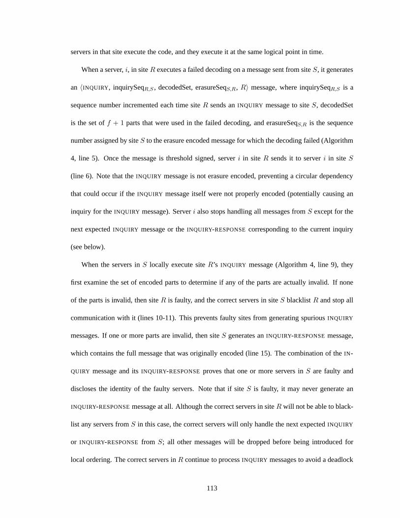
servers in that site execute the code, and they execute it at the same logical point in time.
When a server,i, in siteR executes a failed decoding on a message sent from siteS, it generates
an 〈INQUIRY, inquirySeqR,S , decodedSet, erasureSeqS,R, R〉 message, where inquirySeqR,S is a
sequence number incremented each time siteR sends anINQUIRY message to siteS, decodedSet
is the set off + 1 parts that were used in the failed decoding, and erasureSeqS,R is the sequence
number assigned by siteS to the erasure encoded message for which the decoding failed(Algorithm
4, line 5). Once the message is threshold signed, serveri in site R sends it to serveri in site S
(line 6). Note that theINQUIRY message is not erasure encoded, preventing a circular dependency
that could occur if theINQUIRY message itself were not properly encoded (potentially causing an
inquiry for theINQUIRY message). Serveri also stops handling all messages fromS except for the
next expectedINQUIRY message or theINQUIRY-RESPONSEcorresponding to the current inquiry
(see below).
When the servers inS locally execute siteR’s INQUIRY message (Algorithm 4, line 9), they
first examine the set of encoded parts to determine if any of the parts are actually invalid. If none
of the parts is invalid, then siteR is faulty, and the correct servers in siteS blacklistR and stop all
communication with it (lines 10-11). This prevents faulty sites from generating spuriousINQUIRY
messages. If one or more parts are invalid, then siteS generates anINQUIRY-RESPONSEmessage,
which contains the full message that was originally encoded(line 15). The combination of theIN-
QUIRY message and itsINQUIRY-RESPONSEproves that one or more servers inS are faulty and
discloses the identity of the faulty servers. Note that if site S is faulty, it may never generate an
INQUIRY-RESPONSEmessage at all. Although the correct servers in siteR will not be able to black-
list any servers fromS in this case, the correct servers will only handle the next expectedINQUIRY
or INQUIRY-RESPONSEfrom S; all other messages will be dropped before being introducedfor
local ordering. The correct servers inR continue to processINQUIRY messages to avoid a deadlock
113
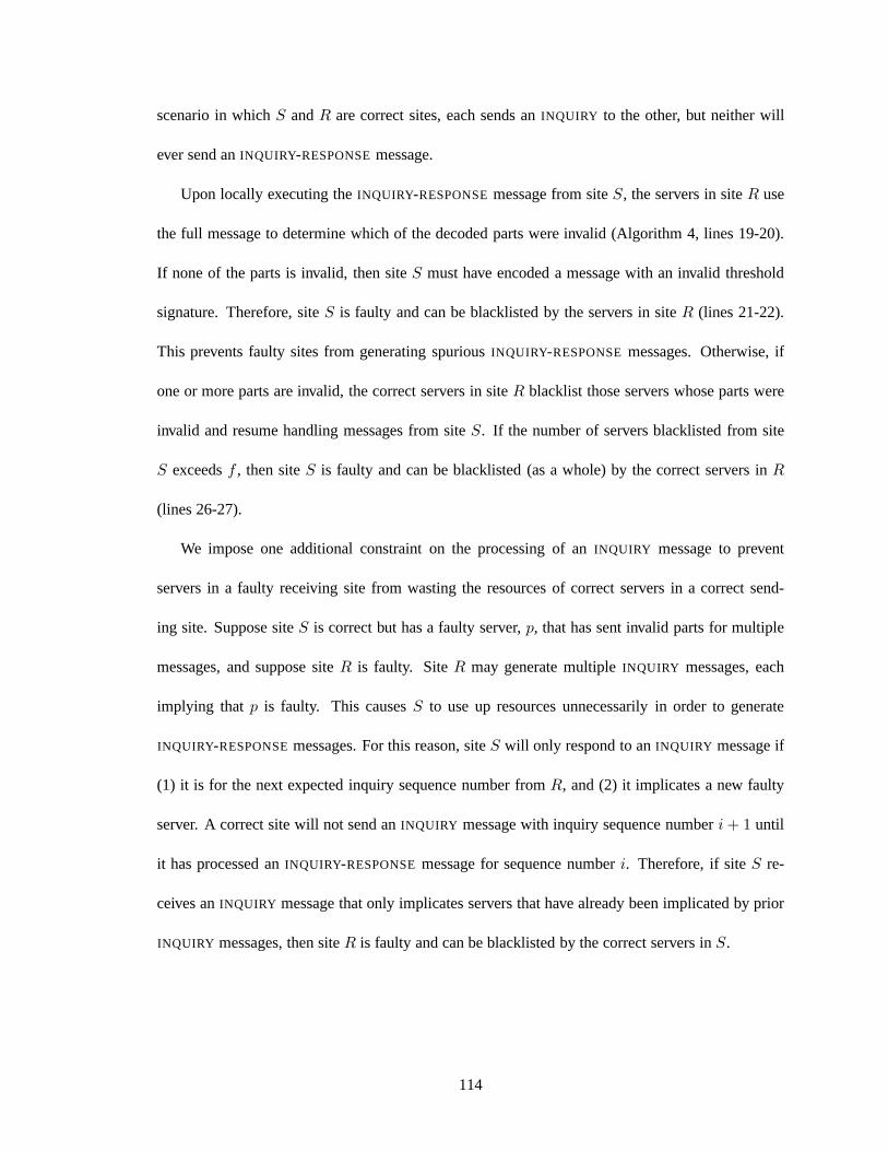
scenario in whichS andR are correct sites, each sends anINQUIRY to the other, but neither will
ever send anINQUIRY-RESPONSEmessage.
Upon locally executing theINQUIRY-RESPONSEmessage from siteS, the servers in siteR use
the full message to determine which of the decoded parts wereinvalid (Algorithm 4, lines 19-20).
If none of the parts is invalid, then siteS must have encoded a message with an invalid threshold
signature. Therefore, siteS is faulty and can be blacklisted by the servers in siteR (lines 21-22).
This prevents faulty sites from generating spuriousINQUIRY-RESPONSEmessages. Otherwise, if
one or more parts are invalid, the correct servers in siteR blacklist those servers whose parts were
invalid and resume handling messages from siteS. If the number of servers blacklisted from site
S exceedsf , then siteS is faulty and can be blacklisted (as a whole) by the correct servers inR
(lines 26-27).
We impose one additional constraint on the processing of anINQUIRY message to prevent
servers in a faulty receiving site from wasting the resources of correct servers in a correct send-
ing site. Suppose siteS is correct but has a faulty server,p, that has sent invalid parts for multiple
messages, and suppose siteR is faulty. SiteR may generate multipleINQUIRY messages, each
implying that p is faulty. This causesS to use up resources unnecessarily in order to generate
INQUIRY-RESPONSEmessages. For this reason, siteS will only respond to anINQUIRY message if
(1) it is for the next expected inquiry sequence number fromR, and (2) it implicates a new faulty
server. A correct site will not send anINQUIRY message with inquiry sequence numberi + 1 until
it has processed anINQUIRY-RESPONSEmessage for sequence numberi. Therefore, if siteS re-
ceives anINQUIRY message that only implicates servers that have already beenimplicated by prior
INQUIRY messages, then siteR is faulty and can be blacklisted by the correct servers inS.
114
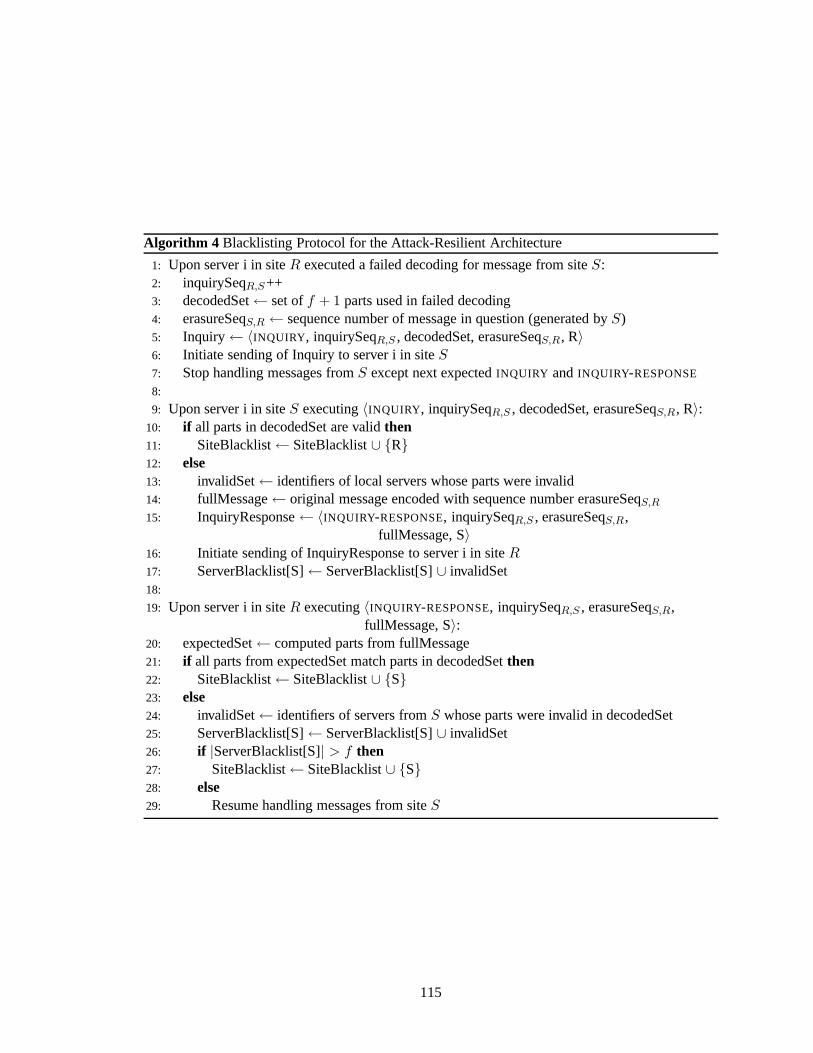
Algorithm 4 Blacklisting Protocol for the Attack-Resilient Architecture
1: Upon server i in siteR executed a failed decoding for message from siteS:2: inquirySeqR,S++3: decodedSet← set off + 1 parts used in failed decoding4: erasureSeqS,R ← sequence number of message in question (generated byS)5: Inquiry← 〈INQUIRY, inquirySeqR,S , decodedSet, erasureSeqS,R, R〉6: Initiate sending of Inquiry to server i in siteS7: Stop handling messages fromS except next expectedINQUIRY andINQUIRY-RESPONSE
8:
9: Upon server i in siteS executing〈INQUIRY, inquirySeqR,S , decodedSet, erasureSeqS,R, R〉:10: if all parts in decodedSet are validthen11: SiteBlacklist← SiteBlacklist∪ {R}12: else13: invalidSet← identifiers of local servers whose parts were invalid14: fullMessage← original message encoded with sequence number erasureSeqS,R
15: InquiryResponse← 〈INQUIRY-RESPONSE, inquirySeqR,S , erasureSeqS,R,fullMessage, S〉
16: Initiate sending of InquiryResponse to server i in siteR17: ServerBlacklist[S]← ServerBlacklist[S]∪ invalidSet18:
19: Upon server i in siteR executing〈INQUIRY-RESPONSE, inquirySeqR,S , erasureSeqS,R,fullMessage, S〉:
20: expectedSet← computed parts from fullMessage21: if all parts from expectedSet match parts in decodedSetthen22: SiteBlacklist← SiteBlacklist∪ {S}23: else24: invalidSet← identifiers of servers fromS whose parts were invalid in decodedSet25: ServerBlacklist[S]← ServerBlacklist[S]∪ invalidSet26: if |ServerBlacklist[S]| > f then27: SiteBlacklist← SiteBlacklist∪ {S}28: else29: Resume handling messages from siteS
115
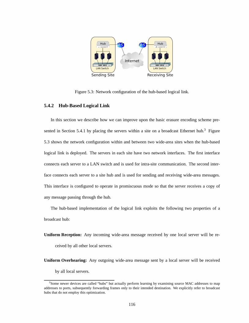
Figure 5.3: Network configuration of the hub-based logical link.
5.4.2 Hub-Based Logical Link
In this section we describe how we can improve upon the basic erasure encoding scheme pre-
sented in Section 5.4.1 by placing the servers within a site on a broadcast Ethernet hub.3 Figure
5.3 shows the network configuration within and between two wide-area sites when the hub-based
logical link is deployed. The servers in each site have two network interfaces. The first interface
connects each server to a LAN switch and is used for intra-site communication. The second inter-
face connects each server to a site hub and is used for sendingand receiving wide-area messages.
This interface is configured to operate in promiscuous mode so that the server receives a copy of
any message passing through the hub.
The hub-based implementation of the logical link exploits the following two properties of a
broadcast hub:
Uniform Reception: Any incoming wide-area message received by one local serverwill be re-
ceived by all other local servers.
Uniform Overhearing: Any outgoing wide-area message sent by a local server will bereceived
by all local servers.
3Some newer devices are called “hubs” but actually perform learning by examining source MAC addresses to mapaddresses to ports, subsequently forwarding frames only totheir intended destination. We explicitly refer to broadcasthubs that do not employ this optimization.
116
When integrated with the basic erasure encoding scheme, a broadcast hub yields several benefits,
which we now describe. The Uniform Reception property implies that as long as the physical
machine that sends an erasure encoded part is correct, all ofthe correct physical machines in the
receiving site will receive the part. This means that any virtual link whose sender is correct will
behave like a correct virtual link, even if the peer is faulty, provided at least one correct physical
machine in the receiving site assumes responsibility for introducing the part for local ordering. Since
there are at least2f + 1 correct servers in the sending site, we can use a(2f + 1, 3f + 1, t/(2f +
1), 2f + 1) MDS code, wheret is the number of bits in the original message. Thus, each erasure
encoded part is1/(2f + 1) the size of the original message, and any2f + 1 of the3f + 1 parts
are sufficient to decode. Using this modified coding improvesthe worst-case aggregate bandwidth
overhead of the logical link to approximately(3f + 1)(1/(2f + 1)), which approaches an overhead
factor of 1.5 asf tends towards infinity, compared to an overhead factor of 3 with the basic erasure
encoding scheme.
The Uniform Overhearing property enables local servers to monitor which erasure encoded parts
were already sent through the hub. If enough parts were already sent, a local server need not send
its own part, saving wide-area bandwidth. Of course, some ofthe parts that the server overhears on
the hub may be faulty, and so the blacklisting protocol described in Section 5.4.1 remains a critical
component of the logical link.
In more detail, we associate with each threshold-signed message two disjoint sets of servers,G1
andG2, where|G1| = 2f + 1 and|G2| = f . The sets are chosen dynamically as a function of the
server identifiers and the sequence number associated with the threshold-signed message. When a
server encodes a message with sequence numberseq, it decides to send its part based on which set
it is in. If servers is in G1, then it sends its erasure encoded part to its peer immediately. If server
s is G2, then it schedules the sending of its part after a local timeout period. During the timeout
117
periods monitors theERASURE messages that arrive on the hub. Servers counts the number of
validly-signedERASUREmessages, from distinct local servers and containingseq, that it receives.
If, before the timeout expires, the count reaches2f + 1, thens cancels the transmission of its part.
If the timeout expires, thens sends its part to its peer. Note that up tof of theERASUREmessages
that s overhears may contain invalid parts. If any of the2f + 1 parts are invalid, the blacklisting
protocol will be initiated by the receiving site, ensuring that it eventually recovers the full message
(provided neither the sending site nor the receiving site isByzantine).
When all of the members ofG1 are correct and the timeout values are set correctly, exactly 2f+1
erasure encoded parts will be sent, each(1/(2f + 1)) the size of the message. This yields a best-
case aggregate bandwidth overhead of approximately 1; the bandwidth overhead factor is slightly
greater than 1 because eachERASURE message carries a digital signature. In the worst case, all
3f + 1 erasure encoded parts will be sent, yielding a bandwidth overhead factor of approximately
1.5. The bandwidth overhead realized in practice is based onthe number of parts actually sent,
which depends on the number of faulty servers and how well thesite’s timing assumptions hold.
There are three potential costs of deploying the hub-based logical link: local computation, local
bandwidth usage, and latency. Since incoming wide-area messages are received on the hub, many
servers in the receiving site will receive a copy of each erasure encoded part. This raises the question
of which server in the receiving site should be responsible for introducing a part for local ordering.
The approach we take is to assign a set off + 1 servers to each incoming part, based on the server
identifiers and the sequence number of the associated threshold-signed message. This ensures that at
least one correct server will introduce each part for ordering. Duplicate copies of a part are ignored
upon local execution. Thus, while the hub improves wide-area bandwidth efficiency, it increases
local computation and bandwidth usage in the receiving sitebecause it requires more events to be
locally ordered. We believe this trade-off is desirable in wide-area systems, whose performance
118
tends to be limited by wide-area bandwidth constraints.
The other potential cost of the hub-based logical link is higher latency compared to the basic
erasure encoding scheme. If any of the2f+1 servers inG1 does not send its part when it is supposed
to, then the servers inG2 will wait a local timeout period before transmitting their parts. In the worst
case, this timeout is incurred in each round of the wide-areaprotocol. A system administrator whose
focus is on minimizing latency may opt to configure the systemso that all servers send their parts
immediately, reducing delay under attack but paying a higher cost in wide-area bandwidth in fault-
free executions (yielding a fixed overhead of approximately1.5).
Finally, we note that while broadcast hubs are a natural fit for our architecture, they are some-
what dated pieces of hardware that are often replaced in favor of switches. Our system can achieve
the same benefit as a hub by using any device meeting the Uniform Reception and Uniform Over-
hearing properties. For example, one can emulate the properties of a hub by using a collection of
network taps. A network tap is a simple device that passes traffic between two endpoints as well as
to a monitoring port, allowing a third party to overhear the traffic.
5.4.3 Dependable Forwarder-Based Logical Link
We now consider the implications of equipping each site witha dependable forwarder(DF), a
dedicated device that sits between the servers in a site and the wide-area network and is responsible
for sending and receiving wide-area messages on the site’s behalf. The basic premise is as follows.
When the physical machines in a site generate a threshold-signed message, they send it to the site’s
dependable forwarder. When the DF receivesf + 1 copies of the message, from distinct servers,
it sends exactly one copy of the message to the DF at each destination site. Upon receiving an
incoming wide-area message, a DF disseminates it to the physical machines in the local site.
We designed the dependable forwarder to be neutral to the wide-area replication protocol be-
119
ing deployed. This makes it simpler to implement and reason about (by avoiding protocol-specific
configuration and dependencies), as well as more generally applicable. Each local server communi-
cates with the local DF via TCP, tagging each message with a message authentication code (MAC)
computed using a symmetric key shared by the local server andthe DF. The DFs send messages to
each other using UDP, just as the servers would if they were communicating directly. Messages sent
between DFs contain MACs computed using the symmetric key shared by each pair of DFs.
After generating a threshold-signed wide-area message, a local server sends it to the DF, pre-
fixing a short header that contains (1) a sequence number, (2)a destination bitmap, (3) the desired
traffic class, and (4) the message length. The sequence number is a 64-bit integer incremented each
time the server wants to send a wide-area message; since local servers generate wide-area messages
in the same order, they will consistently assign sequence numbers to outgoing messages. The des-
tination bitmap is a short bit string used to indicate to which sites the message should be sent. The
traffic class field tells the DF in what traffic class the outgoing message should be sent. The header
is stripped off before the DF sends the message on the wide-area network. Note that the DF does not
need to verify threshold signatures or know anything about the content of the wide-area messages.
Since it is depended upon to be available, the DF should be deployed using best practices,
including protecting it from tampering via physical security and access control and configuring it to
run only necessary services to reduce its vulnerability to software-based compromise. A primary-
backup approach can also be used to fail over to a backup DF in case the primary DF crashes.
As stated in Section 5.1, any number of dependable forwarders can be compromised without
threatening the consistency of the global replication service. Thus, we rely on the DFs to run
correct code and remain available, but not at the risk of making it easier to violate safety. A site
whose DF has been compromised but in whichf or fewer servers have been compromised can
only exhibit faults in the time and performance domains,not in the value domain. The reason
120

this property holds is that the DF passes threshold-signed messages, which even a compromised DF
cannot forge. We believe relying on DFs whose compromise cannot cause inconsistency, rather than
on devices the system requires to be impenetrable in order toguarantee safety, is desirable given the
strong consistency semantics required by systems that use astate machine replication service.
In order to justify the fact that system liveness and performance is placed in the hands of the
dependable forwarders, it is important that their implementation be simple and straightforward so
that the code can be verified for correctness. The DF should also be designed to use a bounded
amount of memory so that faulty servers cannot cause it to runout of resources. We now describe
one possible implementation of the dependable forwarder.
Each DF maintains several counters. First, the DF maintainsa single counter,lastSent, which
stores the sequence number of the last message sent on behalfof the site. The DF also maintains
one counter per local server,lastReceivedi , which stores the sequence number of the last message
received from serveri. To keep track of which messages (and how many copies of them)have
been received from local servers, the DF uses a two-level hash table. The first level maps message
sequence numbers into a second hash table, which maps the entire message (including the prefixed
header but excluding the MAC) to aslot data structure. The slot contains a single copy of the
message (stored the first time the message is received) as well as a tally of the number of copies that
have been received.
Local Message Handling Protocol: Each DF is configured with a parameter,LOCAL-
THRESHOLD, indicating how many copies of a message must be received from local servers before
the message should be sent on the wide area. This value can be set betweenf + 1 and2f + 1
(inclusive). SettingLOCAL-THRESHOLD to f + 1 ensures that at least one correct server wants to
send a message with the given content, while settingLOCAL-THRESHOLD to 2f + 1 ensures that a
majority of the correct servers want to send the given message. Note that theLOCAL-THRESHOLD
121

parameter affects how the DF can be used. For example, if the parameter is set tof + 1, then the
protocol using the DF must ensure that at leastf +1 correct servers generate each outgoing message
so that the threshold will be reached. In our system all correct local servers running Prime generate
each outgoing message, so we could set the parameter as high as 2f + 1. We set the parameter to
f + 1.
The DF expects to receive messages from each local server in sequence number order. AWIN-
DOW parameter dictates how many messages abovelastSentthe DF will accept from a local server
before it (temporarily) stops reading from the corresponding session, which will eventually cause
the session to block until enough servers catch up and more messages can be sent (i.e., untillastSent
increases). This guarantees that at mostWINDOW slots will be allocated at any point in time.
Remote Message Handling Protocol:A strategy similar to the one described above must be
used to bound the amount of resources needed by the dependable forwarder to handle messages from
remote sites. The DF maintains a queue per incoming wide-area link; each queue has a bounded
size. Incoming messages are placed in the appropriate queueand must be delivered to the servers
in the local site; an incoming message is discarded if the corresponding queue is full. Since faulty
local servers may fail to read the messages sent by the dependable forwarder, bounding the memory
requirements of the DF implies that the DF must be able to “forget” about a message (i.e., perform
garbage collection) before it has successfully sent it to all local servers. The DF can be configured to
perform garbage collection when it has successfully written the message to betweenf +1 and2f +1
local servers, depending on the requirements of the replication protocol. The former guarantees that
at least one correct local server will receive the message, while the latter guarantees that a majority of
correct servers will receive the message. In our implementation, which uses Prime as the local state
machine replication protocol, we set the garbage collection parameter tof + 1, since it is sufficient
for one correct server to introduce each incoming global protocol message for local ordering.
122
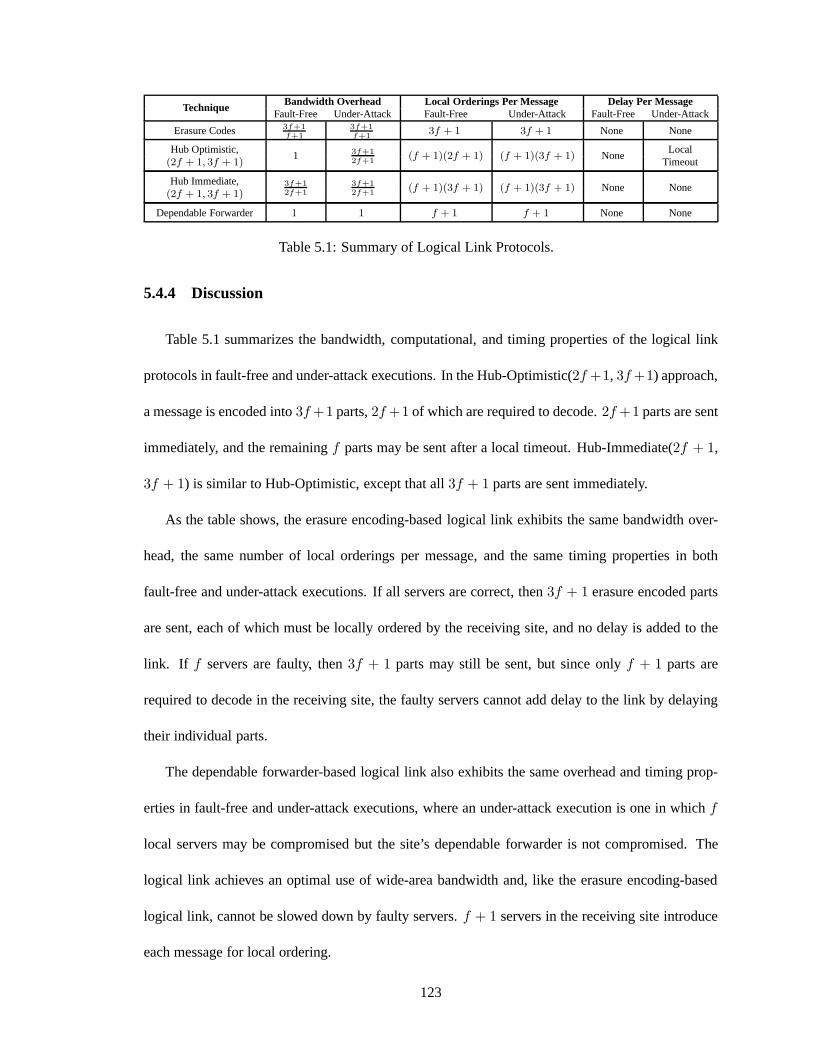
TechniqueBandwidth Overhead Local Orderings Per Message Delay Per Message
Fault-Free Under-Attack Fault-Free Under-Attack Fault-Free Under-Attack
Erasure Codes 3f+1
f+1
3f+1
f+13f + 1 3f + 1 None None
Hub Optimistic,1 3f+1
2f+1(f + 1)(2f + 1) (f + 1)(3f + 1) None
Local(2f + 1, 3f + 1) Timeout
Hub Immediate, 3f+1
2f+1
3f+1
2f+1(f + 1)(3f + 1) (f + 1)(3f + 1) None None
(2f + 1, 3f + 1)
Dependable Forwarder 1 1 f + 1 f + 1 None None
Table 5.1: Summary of Logical Link Protocols.
5.4.4 Discussion
Table 5.1 summarizes the bandwidth, computational, and timing properties of the logical link
protocols in fault-free and under-attack executions. In the Hub-Optimistic(2f +1, 3f +1) approach,
a message is encoded into3f +1 parts,2f +1 of which are required to decode.2f +1 parts are sent
immediately, and the remainingf parts may be sent after a local timeout. Hub-Immediate(2f + 1,
3f + 1) is similar to Hub-Optimistic, except that all3f + 1 parts are sent immediately.
As the table shows, the erasure encoding-based logical linkexhibits the same bandwidth over-
head, the same number of local orderings per message, and thesame timing properties in both
fault-free and under-attack executions. If all servers arecorrect, then3f + 1 erasure encoded parts
are sent, each of which must be locally ordered by the receiving site, and no delay is added to the
link. If f servers are faulty, then3f + 1 parts may still be sent, but since onlyf + 1 parts are
required to decode in the receiving site, the faulty serverscannot add delay to the link by delaying
their individual parts.
The dependable forwarder-based logical link also exhibitsthe same overhead and timing prop-
erties in fault-free and under-attack executions, where anunder-attack execution is one in whichf
local servers may be compromised but the site’s dependable forwarder is not compromised. The
logical link achieves an optimal use of wide-area bandwidthand, like the erasure encoding-based
logical link, cannot be slowed down by faulty servers.f + 1 servers in the receiving site introduce
each message for local ordering.
123

The hub-based logical links demonstrate a trade-off between throughput and latency in fault-free
and under-attack executions. Hub-Optimistic achieves near-optimal wide-area bandwidth usage in
fault-free runs, but faulty servers can add one local timeout of latency by withholding their erasure
encoded parts. Note that this latency may also be incurred infault-free executions when the timeout
value used for monitoring the hub is set too low. In the fault-free case, exactly2f + 1 parts are
sent, each of which is introduced for local ordering byf + 1 servers in the receiving site. Whenf
servers are faulty, the local ordering overhead increases to (f + 1) ∗ (3f + 1), because all3f + 1
erasure encoded parts are sent, each of which is introduced for local ordering byf + 1 servers.
When the Hub-Immediate approach is used, the bandwidth overhead is the same in fault-free and
under-attack executions (and is higher than the overhead ofHub-Optimistic in fault-free runs), but
the faulty servers cannot add delay to the link. In all executions,3f +1 parts are sent, each of which
is introduced for local ordering byf + 1 servers in the receiving site.
We conclude this section by commenting on some of the key properties of the logical links. One
important property of all three types of logical links is that they specifically avoid requiring correct
servers to dynamically determine how quickly a sending entity should be able to pass messages.
This type of monitoring would be necessary to ensure good performance if the site relied on a
single untrusted server to send messages, as was done in BLink [16]. BLink also requires feedback
from the remote site, in the form of acknowledgements, to assess the performance of the logical
link, which makes it even more difficult to determine which party is to blame (the local forwarder or
the remote peer) if performance seems slow. The use of redundant sending in the erasure encoding-
and hub-based logical links removes the need for such monitoring, and the use of erasure codes
reduces the overhead of redundant sending. In the one case where the logical link is configured to
rely on a single entity (i.e., when the dependable forwarder-based link is deployed), the entity is
specifically designed so that the reliance is justified.
124
The second important property shared by the logical links isthat they offer predictable perfor-
mance when the network is stable. When the faulty servers do not submit invalid erasure encoded
parts, they either cannot delay a message, or they can delay it only by the duration of a local timeout.
When the faulty servers do submit invalid parts, they are blacklisted, after which they can no longer
cause any delay. The predictability of the logical links enables them to support global state machine
replication protocols that have relatively strong timing assumptions, as discussed in Section 5.6.
5.5 Putting It All Together
In this section we show how the pieces of the attack-resilient architecture fit together to form
a complete system. Figure 5.4 depicts the internal organization of a replication server when the
dependable forwarder-based logical link is deployed. As mentioned in Section 5.3, we chose to
use Prime in both levels of the hierarchy (denoted Local Prime and Global Prime in the figure).
The local and global instances of Prime are cleanly separated and operate on different sets of data
structures.
There are three kinds of messages that flow in Figure 5.4: Local Prime messages, Global Prime
messages, and partial signatures (i.e., pieces of a threshold signature) that are matched with their
peer pieces. Each of these kinds of messages has two flows: from the network and to the network.
We now describe each of these flows.
When a Local Prime message arrives from the network, it is examined by the Network Dis-
patcher, which forwards it to Local Prime for processing (Figure 5.4, left side). When a server
generates a Local Prime message that should be sent on the network, the message passes through
the Local Merkle Tree module (explained below) and is then digitally signed with an RSA signa-
ture. The message is then sent on the local-area network. Local Prime messages are sent in the
LOCAL-TIMELY andLOCAL-BOUNDED traffic classes.
125
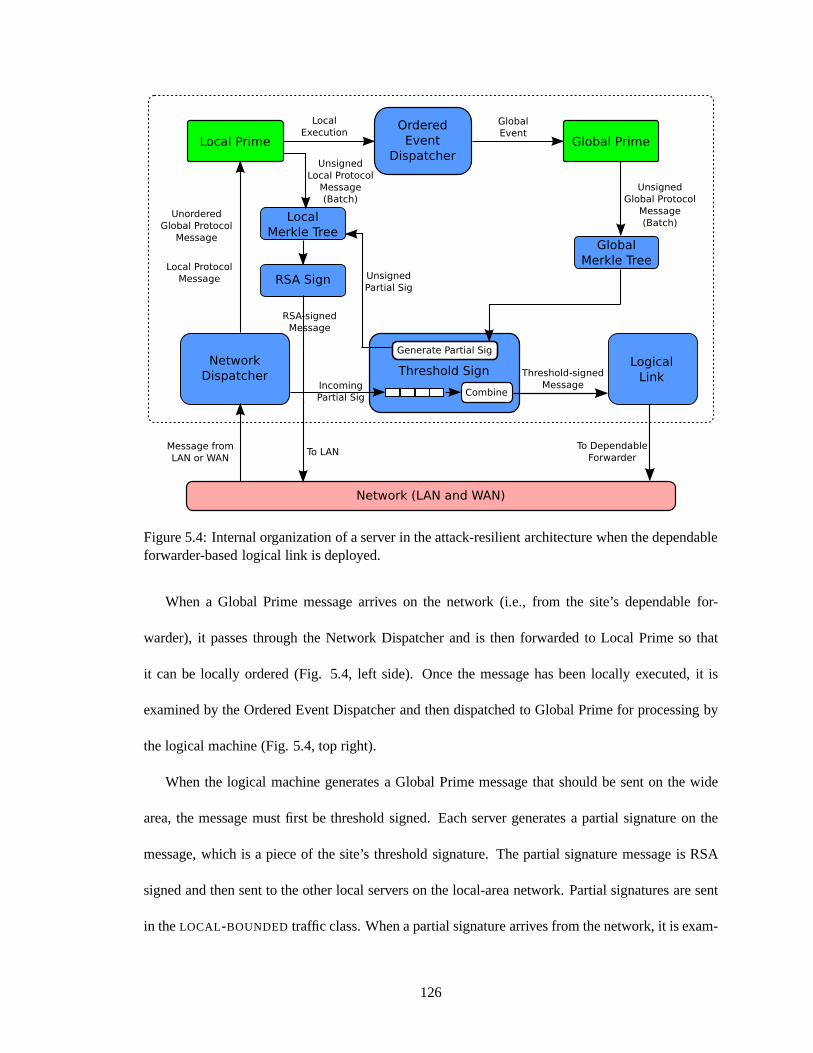
Figure 5.4: Internal organization of a server in the attack-resilient architecture when the dependableforwarder-based logical link is deployed.
When a Global Prime message arrives on the network (i.e., from the site’s dependable for-
warder), it passes through the Network Dispatcher and is then forwarded to Local Prime so that
it can be locally ordered (Fig. 5.4, left side). Once the message has been locally executed, it is
examined by the Ordered Event Dispatcher and then dispatched to Global Prime for processing by
the logical machine (Fig. 5.4, top right).
When the logical machine generates a Global Prime message that should be sent on the wide
area, the message must first be threshold signed. Each servergenerates a partial signature on the
message, which is a piece of the site’s threshold signature.The partial signature message is RSA
signed and then sent to the other local servers on the local-area network. Partial signatures are sent
in theLOCAL-BOUNDED traffic class. When a partial signature arrives from the network, it is exam-
126
ined by the Network Dispatcher and then passed directly to the Threshold Sign module, (Fig. 5.4,
bottom left), without undergoing a local ordering. When each server collectsf +1 matching partial
signatures, it combines them to obtain the threshold-signed message (Fig. 5.4, bottom middle). The
message is then passed to the Logical Link, which sends it over the local-area network to the site’s
dependable forwarder. The dependable forwarder (not shown) sends the message to the destination
dependable forwarders over the wide-area network. Messages that were designated by the logical
machine asVIRTUAL -TIMELY are sent in theGLOBAL-TIMELY traffic class, and messages that were
designated asVIRTUAL -BOUNDED are sent in theGLOBAL-BOUNDED traffic class.
To amortize the computational overhead of generating digital and threshold signatures, each
server makes use of a Merkle Tree [57], a cryptographic data structure that can be used to sign
multiple messages at once. Our previous work on the customizable architecture [16] also employed
Merkle trees, but only for wide-area messages; we use it herefor both local and global protocol
messages. When a server is ready to sign a batch of messages, it places the digests of the messages
in the leaves of a binary tree, one per leaf. An internal node in the tree stores the digest of the
concatenation of its two children. A server signs the batch by signing the digest at the root of the
tree. In order to ensure that each signed message is verifiable, the server includes in the outgoing
message the sibling digests along the path from the message to the root of the tree. This enables the
verifier to reconstruct the root digest and verify the signature.
Using a Merkle tree to threshold sign wide-area messages actually increases their size slightly
because a logarithmic number of digests must be appended to enable signature verification. While
this may seem counterintuitive (after all, we have been focused on limiting wide-area traffic), the
ability to aggregate signatures is what makes the logical machine throughput high enough so that
the system is bandwidth constrained, rather than CPU constrained. Thus, it is worth paying the cost
in digests to achieve much higher system throughput.
127
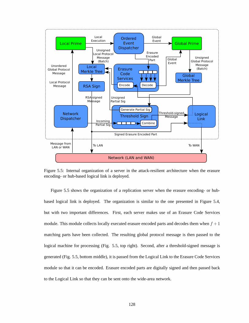
Figure 5.5: Internal organization of a server in the attack-resilient architecture when the erasureencoding- or hub-based logical link is deployed.
Figure 5.5 shows the organization of a replication server when the erasure encoding- or hub-
based logical link is deployed. The organization is similarto the one presented in Figure 5.4,
but with two important differences. First, each server makes use of an Erasure Code Services
module. This module collects locally executed erasure encoded parts and decodes them whenf +1
matching parts have been collected. The resulting global protocol message is then passed to the
logical machine for processing (Fig. 5.5, top right). Second, after a threshold-signed message is
generated (Fig. 5.5, bottom middle), it is passed from the Logical Link to the Erasure Code Services
module so that it can be encoded. Erasure encoded parts are digitally signed and then passed back
to the Logical Link so that they can be sent onto the wide-areanetwork.
128

5.5.1 Handling Non-Determinism in the Global Instance of Prime
Recall that state machine replication can be used to replicate an application as long as it is
deterministic. Prime, however, is not a completely deterministic protocol. A server can take ac-
tion based on the expiration of a timeout (e.g., so that messages can be sent periodically), and the
Suspect-Leader sub-protocol takes action based on local time measurements. This section discusses
how Prime’s non-deterministic events can be consistently handled by the logical machine. Note
that non-determinism is not a problem for the local instanceof Prime because it runs on the native
hardware of a single physical machine.
We first explain how to implement the expiration of a logical machine timeout, which might
fire asynchronously at the physical machines implementing the logical machine. Since the logical
machine is event based, the timeout is only set in response toprocessing some global event (i.e.,
when the event is locally executed). Therefore, each logical machine timeout can be uniquely
identified by the local sequence number of the global event that caused the timeout to be set. When
a physical machine believes enough time has elapsed (on its local clock) since the timeout was set, it
introduces for (local) preordering aTIMEOUT-REQUESTmessage, containing the sequence number
associated with the logical machine timeout. A logical machine timeout is said to expire when the
logical machine executes2f +1 such timeout requests. This ensures that faulty machines are unable
to unilaterally trigger, or block, a logical machine timeout.
We now describe how to handle non-determinism in the Suspect-Leader sub-protocol. There
are two sources of non-determinism that must be addressed. First, the logical machine periodically
measures the turnaround time provided by the leader logicalmachine in the current view. The
physical machines must decide on a single measurement valueso that they evaluate the leader
consistently. This measurement is done periodically and istriggered in response to a logical machine
timeout. When a physical machine sends theTIMEOUT-REQUEST to implement this timeout, it
129
piggybacks the turnaround time that it measured based on itslocal clock. When the logical machine
timeout expires (i.e., after2f + 1 suchTIMEOUT-REQUESTmessages have been locally executed),
the physical machines sort the2f + 1 suggested values and select the middle value as the agreed
upon turnaround time for evaluating the leader. Choosing the middle value guarantees that the
chosen value is either (1) a value proposed by a correct physical machine, or (2) a value that falls
within the range of values proposed by the correct physical machines.
The other source of non-determinism in Suspect-Leader occurs when a logical machine needs
to construct anRTT-MEASURE message. The message is constructed after locally executing an
RTT-PONGmessage. In order to construct a threshold-signedRTT-MEASURE, the physical machines
need to decide on a single value for the measured round-trip time. Each physical machine computes
a local round-trip time measurement when it locally executes theRTT-PONG. A physical machine
then introduces for local preordering an event containing the local measurement. When the logi-
cal machine executes2f + 1 such measurements, the physical machines build anRTT-MEASURE
message based on the middle value.
5.6 Service Properties
The safety, liveness, and performance properties providedby the attack-resilient architecture
depend on the protocols deployed in the local sites and on thewide-area network. This section
specifies the system’s service properties assuming that Prime is used in both levels of the hierarchy.
5.6.1 Safety Properties
The attack-resilient architecture meets similar safety properties to those met by a flat system
running Prime (see Section 4.1). The only difference in the specification of the first three safety
properties is that they limit the number of sites that are faulty, rather than the number of servers:
130

DEFINITION 5.6.1 Safety-S1: In all executions in whichF or fewer sites are faulty, the output
sequences of two correct servers are identical, or one is a prefix of the other.
DEFINITION 5.6.2 Safety-S2:In all executions in whichF or fewer sites are faulty, each opera-
tion appears in the output sequence of a correct server at most once.
DEFINITION 5.6.3 Safety-S3:In all executions in whichF or fewer sites are faulty, each opera-
tion in the output sequence of a correct server is valid.
The hierarchical system also meets a similar linearizability property to the Modified-
Linearizability property met by Prime in a flat system (see Section 4.1). The only difference is
the condition under which an operation is said tocomplete. In the hierarchical system, an operation
completes when it has been output by at least one correct server in F + 1 sites. We refer to the re-
sulting property asHierarchical-Modified-Linearizability. Thus, the system’s fourth safety property
can be specified as follows:
DEFINITION 5.6.4 Safety-S4:In all executions in whichF or fewer sites are faulty, replies for
operations submitted by correct clients satisfy Hierarchical-Modified-Linearizability.
5.6.2 Liveness and Performance Properties
The liveness and performance properties of the attack-resilient architecture running Prime as
the global protocol are similar to the liveness and performance properties of a flat system running
Prime with one server per site. However, as noted in Section 5.3.2, whereas in a flat system one can
assume that (when the system is not overloaded) processing time is bounded and message delay is
composed of the delay from the network itself and the processing time of the receiving server, the
situation is more complicated in a hierarchical system. Logical machine processing time is related
to the performance of the local state machine replication protocol; message delay between logical
131
machines is influenced by the performance of the threshold signature, logical link, and local state
machine replication protocols, in addition to the delay from the network itself.
Our goal in this section is to show that the hierarchical system providesGLOBAL-LIVENESS and
GLOBAL-BOUNDED-DELAY (defined formally below), which are analogous to the corresponding
properties when Prime is run in a flat system (see Definitions 4.1.12 and 4.1.13). Recall from Section
4.1 that to show these properties hold in a flat system, we mustconsider the level of synchrony
provided by each of Prime’s traffic classes (i.e.,TIMELY andBOUNDED). We take the same approach
in the hierarchical system, except that the traffic classes we consider arevirtual (see Section 5.1).
In other words, we must show that the pieces of the hierarchical architecture are timely enough
so that theVIRTUAL -TIMELY andVIRTUAL -BOUNDED traffic classes provide the required level of
synchrony. This will enable us to show that the system as a whole meetsGLOBAL-LIVENESS and
GLOBAL-BOUNDED-DELAY .
Throughout this section, it is important to remember that although we will be showing that
GLOBAL-LIVENESS andGLOBAL-BOUNDED-DELAY hold by making statements about the timeli-
ness of the virtual traffic classes, the virtual traffic classes are conceptual. When a logical machine
sends a message, it may designate it asVIRTUAL -BOUNDED or VIRTUAL -TIMELY , but the physical
messages that are sent among servers in the site to thresholdsign the outgoing message are sent in
the LOCAL-BOUNDED traffic class, and the physical messages that are actually sent between sites
(on the physical network) are designated asGLOBAL-TIMELY or GLOBAL-BOUNDED. Similarly,
the physical messages sent among servers in a site to order the reception of the message by the
logical machine are designated asLOCAL-TIMELY or LOCAL-BOUNDED. Thus, we use the virtual
traffic classes to reason about what degree of timeliness is required of the pieces of the system, but
ultimately we will need to show that each of the pieces can actually meet its required degree of
timeliness.
132
In the rest of this section, we first discuss the conditions under which a Prime-based logical
machine exhibits bounded processing time. This is a necessary condition both to bound the time
that it takes to introduce an operation into the system and for the virtual traffic classes to have the
required degree of timeliness. We then show that the rest of the pieces of the hierarchical architecture
are timely enough to provide the virtual traffic classes withthe necessary degree of synchrony.
Achieving Bounded Logical Machine Processing Time
As stated in Section 5.3.3, a Prime-based logical machine exhibits bounded processing time
(i.e., meetsBOUNDED-DELAY at the local level) when three conditions hold: (1) the network is
sufficiently stable, (2) all events requiring bounded processing time are introduced for local ordering
by at least one correct server, and (3) the load offered to thelogical machine does not exceed the
maximum throughput of the logical machine. We now consider each of these conditions in turn.
The degree of network stability needed to meetBOUNDED-DELAY at the local level was stated as
Stability-S3in Section 4.1 (see Definition 4.1.10). We restate this property here asLocal-Stability-
S3, modifying the definition slightly to take into account the traffic classes used within a site in the
lower level of the hierarchy:
DEFINITION 5.6.5 Local-Stability-S3: Let TlocalT imely and TlocalBounded be traffic classes con-
taining messages designated asLOCAL-TIMELY and LOCAL-BOUNDED, respectively. Then there
exists a stable set, Stable, a network-specific constant,KLocal, and a time,t, after which Bounded-
Variance(TlocalT imely , Stable,KLocal) and Eventual-Synchrony(TlocalBounded , Stable) hold.
As stated in Section 4.1, we believeLocal-Stability-S3can be made to hold in well-provisioned
local-area networks, where latency is often predictable and bandwidth is plentiful. Queuing is
unlikely to occur on such networks. In addition, messages inthe LOCAL-TIMELY traffic class can
be processed with higher priority so that theBounded-Variancecondition has sufficient coverage.
133
We now discuss how the system meets condition (2), which requires any global event that
must be processed by the logical machine in bounded time forGLOBAL-LIVENESS or GLOBAL-
BOUNDED-DELAY to hold to be introduced for local ordering by at least one correct server. There
are two classes of events locally ordered by the logical machine. In the first class, the event to be
ordered consists of a single message. For example, when the dependable forwarder-based logical
link is deployed, each server in the receiving site receivesa complete global protocol message.
Events in this class are introduced for local ordering byf + 1 servers, at least one of which is
correct. In the second class, the event to be ordered is broken into pieces, and the logical machine
processes the event when it executes a threshold number of pieces,T . Events in this class include
erasure encoded parts (when the erasure encoding- or hub-based logical link is deployed) and the
TIMEOUT-REQUEST messages used to expire a logical machine timeout. The system guarantees
that correct servers introduce at leastT pieces for local ordering, so it is as if a single correct server
introduced the complete event for local ordering. The blacklisting protocol used by the logical link
ensures that there exists a time after which the faulty servers do not disrupt the decoding process.
Finally, Prime providesBOUNDED-DELAY at the local level when the load offered to the logical
machine does not exceed its throughput. Without this property, queues of unordered global protocol
messages could build up, effectively increasing the logical machine processing time. There are
two requirements to meeting this condition. First, the rateat which a site’s local clients submit
operations to the system must be limited. This prevents the logical machine from being overloaded
by locally-submitted operations. Note that this requirement is also needed in a flat architecture,
where the processing delay for operations submitted to a single server would grow if the server
became overloaded. Second, the rate at which incoming global messages arrive on the logical links
must not be too great. Because the number of incoming global protocol messages that need to be
locally ordered by the logical machine is limited by the wide-area bandwidth, we believe a well-
134
engineered logical machine is likely to be capable of doing much more processing than it needs to
do and is unlikely to become overloaded. Indeed, in our own tests, performance was limited by
wide-area bandwidth rather than the processing capabilityof the logical machine.
Supporting Prime’s Virtual Traffic Classes
In order for the system to achieveGLOBAL-LIVENESS and GLOBAL-BOUNDED-DELAY , the
communication delay for messages sent between logical machines (i.e., for messages in Prime’s
virtual traffic classes) must meet the same stability properties as those required when Prime runs
in a flat system. As noted above, the key difference introduced by the hierarchical architecture
compared to a flat system is that the communication delay depends not only on the stability of the
network itself, but also on the performance characteristics of the threshold signature, logical link,
and local state machine replication protocols.
We begin by noting that whereas flat Prime required a stable set of servers to guarantee liveness
and performance, the global instance of Prime running in theattack-resilient architecture requires a
stable set of sites:
DEFINITION 5.6.6 A global stable setis a set of at least2F + 1 correct sites,Stable, such that
there exists a time after which each site in the set exhibits bounded logical machine processing time.
We refer to the members ofStableas thestable sites.
The following two definitions state two stability properties that will be used to define the level
of synchrony required from the virtual traffic classes:
DEFINITION 5.6.7 Virtual-Eventual-Synchrony(T , S): For each pair of logical machines,S1 ∈ S
andS2 ∈ S, any message in traffic classT sent fromS1 to S2 will arrive at and be processed byS2
within some unknown bounded time.
135

DEFINITION 5.6.8 Virtual-Bounded-Variance(T , S, K): For each pair of logical machines,S1 ∈
S andS2 ∈ S, there exists a value, MinLat(S1, S2), unknown to the logical machines, such that
if S1 sends a message in traffic classT to S2, it will arrive at and be processed byS2 with delay
∆S1,S2, where MinLat(S1, S2) ≤ ∆S1,S2
≤Min Lat(S1, S2) ∗K.
Note that Definitions 5.6.7 and 5.6.8 are specified with respect to pairs of logical machines. To
reiterate the point stated above, we must show that the components of the hierarchical architecture
are timely enough so that the virtual traffic classes, which (conceptually) carry messages between
logical machines, provide a sufficient degree of timelinessto the global instance of Prime.
Given Definitions 5.6.7 and 5.6.8, we next specify the stability constraint that the system needs
to meetGLOBAL-LIVENESS:
DEFINITION 5.6.9 Virtual-Stability-S2: Let TvirtualT imely be a traffic class containing all mes-
sages designated asVIRTUAL -TIMELY . Then there exists a global stable set, GS, a network-
specific constant,KV irtual, and a time,t, after which Virtual-Bounded-Variance(TvirtualT imely , GS,
KV irtual) holds.
In order to meetGLOBAL-BOUNDED-DELAY , the system requires the following stronger stabil-
ity constraint:
DEFINITION 5.6.10 Virtual-Stability-S3: Let TvirtualT imely andTvirtualBounded be traffic classes
containing messages designated asVIRTUAL -TIMELY and VIRTUAL -BOUNDED, respectively.
Then there exists a global stable set, GS, a network-specificconstant,KV irtual, and a time,
t, after which Virtual-Bounded-Variance(TvirtualT imely , GS, KV irtual) and Virtual-Eventual-
Synchrony(TvirtualBounded , GS) hold.
Given the above definitions, we now state theGLOBAL-LIVENESS and GLOBAL-BOUNDED-
DELAY properties met by the hierarchical architecture:
136

DEFINITION 5.6.11 GLOBAL-PRIME-LIVENESS: If Virtual-Stability-S2holds for a global stable
set, GS, and no more thanF sites are faulty, then if a stable server in siteS ∈ GS receives an
operation from a correct client, the operation will eventually be executed by all stable servers in all
sites in GS.
DEFINITION 5.6.12 GLOBAL-BOUNDED-DELAY : If Virtual-Stability-S3holds for a global stable
set, GS, and no more thanF sites are faulty, then there exists a time after which the latency between
a stable server in siteS ∈ GS receiving a client operation and all stable servers in all sites in GS
executing that operation is upper bounded.
In the remainder of this section, we present the timing properties needed from the components of
the hierarchical architecture so thatVirtual-Stability-S2andVirtual-Stability-S3hold. This amounts
to showing howVirtual-Eventual-SynchronyandVirtual-Bounded-Variancecan be made to hold for
a global stable set of sites.
Achieving Virtual-Eventual-Synchrony: To meetVirtual-Eventual-Synchrony, each compo-
nent that contributes to the communication delay between logical machines (i.e., the threshold signa-
ture protocol, the logical link protocol, the local state machine replication protocol, and the network
itself) must add a bounded amount of delay. We already described the conditions under which the
logical machine exhibits bounded processing time. SinceVirtual-Stability-S3requires messages in
the VIRTUAL -BOUNDED traffic class to meetVirtual-Eventual-Synchrony, we require the physical
network to deliver messages in theGLOBAL-BOUNDED traffic class in bounded time:
DEFINITION 5.6.13 Global-Eventual-Synchrony: Let GS be a global state set of sites. Then for
each pair of sites,S1 ∈ GS andS2 ∈ GS, any message designated asGLOBAL-BOUNDED sent
from a stable serverr1 ∈ S1 to a stable serverr2 ∈ S2 will arrive within some unknown bounded
time.
137
It remains to be shown that the threshold signature and logical link protocols add a bounded
amount of delay to the communication link between logical machines. The threshold signature
protocol involves a single round of communication and a bounded amount of computation. Partial
signatures are sent in theLOCAL-BOUNDED traffic class. Therefore, when all local servers are cor-
rect andLocal-Stability-S3holds, the protocol will complete in a bounded amount of time. Faulty
servers may temporarily disrupt the protocol by submittinginvalid partial signatures. The black-
listing protocol guarantees that each faulty server can disrupt the combining process at most once.
Thus, there exists a time after which the threshold signature protocol completes in a bounded time.
The logical link protocols also contribute a bounded amountof delay. As argued in Section
5.4.4, in the erasure encoding- and dependable forwarder-based logical links, the faulty servers
cannot delay a message from being sent on time. In the hub-based logical link, the faulty servers can
only introduce a small, bounded amount of delay into the link(i.e., the value of the local timeout).
Servers that send invalid erasure encoded parts are blacklisted. Therefore, there exists a time after
which at most a bounded amount of delay will be introduced by the logical link protocol.
Note that meetingVirtual-Eventual-Synchronyalso requires the Merkle Tree modules to add a
bounded amount of delay to the logical link. For the local Merkle Tree module (i.e., the one used
to aggregate the generation of standard digital signatures), this is achieved by capping the period
during which unsigned messages are collected and by cappingthe number of messages that may be
aggregated into a single batch. For the global Merkle Tree module (i.e., the one used to aggregate the
generation of threshold signatures), bounded processing time is achieved as long as the input batch
size does not grow without bound. In practice, since computing message digests is several orders
of magnitudes faster than computing signatures, the processing time of the Merkle Tree module can
be treated as constant.
Achieving Virtual-Bounded-Variance: To meetVirtual-Bounded-Variancefor messages in
138
theVIRTUAL -TIMELY traffic class, we need a stronger degree of stability from thenetwork itself for
messages in theGLOBAL-TIMELY traffic class:
DEFINITION 5.6.14 Global-Bounded-Variance(K): Let GS be a global stable set of sites. Then
for each pair of sites,S1 ∈ GS and S2 ∈ GS, there exists a value, MinLat(S1, S2), unknown
to the servers in the sites, such that if a stable serverr1 ∈ S1 sends a message designated as
GLOBAL-TIMELY to a stable serverr2 ∈ S2, the message will arrive with delay∆S1,S2, where
Min Lat(S1, S2) ≤∆S1,S2≤ Min Lat(S1, S2) ∗K.
To make Definition 5.6.14 hold, one can use a quality of service mechanism such as Diff-Serv
[24] to separate the low-volumeGLOBAL-TIMELY traffic from the high-volumeGLOBAL-BOUNDED
traffic. This is the same approach as the one that can be used when Prime is run in a flat architecture.
Given that the remaining components of the architecture canadd a bounded amount of delay to
the communication link between logical machines, the challenge is to choose a suitable constant,
KV irtual, that defines the tolerated degree of variability for messages in theVIRTUAL -TIMELY traf-
fic class (see Definitions 5.6.9 and 5.6.10). The constant should take into account the expected
variability of the network itself, as well as of the logical machine processing time. When the hub-
based logical link is deployed, the constant should also account for the fact that some messages may
have a delay larger by the value of a local timeout. Compared to the wide-area network delay, the
variability contributed by the threshold signature protocol is likely to be negligible.
5.7 Performance Evaluation
In this section we evaluate a prototype implementation of our attack-resilient architecture, fo-
cusing on the performance implications of deploying the logical link protocols described in Section
5.4.
139
5.7.1 Testbed and Network Setup
We performed our experiments on a cluster of twenty 3.2 GHz, 64-bit Intel Xeon computers.
We emulated a wide-area system consisting of 7 sites, each with 7 servers. Such a system can tol-
erate the complete compromise of 2 sites and can tolerate 2 Byzantine faults in each of the other 5
sites. We ran one fully deployed site on 7 machines (with one server per machine) and emulated
the other 6 wide-area sites using one machine per site. The remaining machines were used to run
client processes and to emulate the wide-area topology. We used the Spines [9] messaging system
to place bandwidth and latency constraints on the links between sites. We limited the aggregate
outgoing bandwidth from each site to 10 Mbps and placed 50 ms delay between wide-area sites. No
constraints were placed on the links between the servers in the fully deployed site (which commu-
nicated via a Gigabit switch) or between clients and their local servers. Clients submit one update
operation (containing 200 bytes of data, representative ofa typical SQL query) and wait for proof
that the operation was ordered before submitting their nextoperation. Clients were distributed as
evenly as possible among the sites.
The emulated sites process wide-area protocol events afterwaiting an amount of time deter-
mined by measuring the local ordering delays in the non-emulated site. The wide-area messages
generated by the emulated sites are exactly the same as if thesites were not emulated, except that
they are not threshold signed; the messages contain 128 filler bytes to emulate the bandwidth cost of
a signature, and the emulated sites busy-waited for the timerequired to generate partial signatures
and combine them in order to emulate the computational overhead.
We used OpenSSL [6] for generating and verifying RSA signatures and for computing message
digests. The computers in our cluster can compute a 1024-bitRSA signature in 1.3 ms and verify it
in 0.07 ms. We used the OpenTC implementation [7] of Shoup’s threshold RSA signature scheme
for generating threshold signatures. We used Luby’s implementation of the Cauchy-based Reed-
140

Solomon erasure encoding scheme [2,25] for performing coding operations.
5.7.2 Test Configurations
Erasure Encoding-Based Logical Link: In the erasure encoding-based logical link, the
servers encode threshold-signed messages into 7 parts, andeach server sends a part to its peer
in the receiving site. The emulated sites send and receive all erasure encoded parts on behalf of
the servers they emulate. Multiple erasure encoded parts are packed into a single physical message
(which is then digitally signed) to amortize the bandwidth overhead of the digital signature. To
evaluate the performance of the logical link under attack, the faulty servers delayed sending their
erasure encoded parts by 300 ms in an attempt to add latency tothe ordering path.
Hub-Based Logical Link: We emulated the use of a hub by having servers (1) locally broad-
cast outgoing wide-area messages before sending them and (2) locally broadcast incoming wide-
area messages before processing them. Servers were assigned to either the groupG1 or G2 based
on their server identifiers and sequence numbers contained in the messages. For example, servers
1 through 5 were in the first group for message 1, servers 2 through 6 for message 2, and so on,
wrapping around modulo 7. We used a similar strategy to assign the responsibility of proposing
incoming messages for local ordering to 3 servers.
We tested the hub-based logical link in four configurations.The first is designated as Hub-
Optimistic. Wide-area messages are encoded into 7 parts, 5 of which are needed to decode. 5
servers send their parts immediately, and the other 2 only send their parts if they do not overhear
enough parts before their local timeout expires. All servers were assumed to be correct. Servers in
the second group used a local timeout of 25 ms. This value was chosen after experimentation as
one that would not allow faulty servers to cause too much delay when the system is under attack,
but which was usually long enough so that correct servers inG2 would not have to send their parts.
141
We observed correct servers to send their parts between0% and10% of the time. Emulated sites
conservatively sent additional parts from servers inG2 10% of the time.
In the second configuration, Hub-Immediate, all servers were correct and sent their parts imme-
diately. Thus, this configuration does not utilize the monitoring of outgoing wide-area messages.
Incoming messages are still introduced for local ordering by f + 1 servers. In the third configura-
tion, we ran an attack on the Hub-Optimistic logical link. Faulty servers in the first group delayed
sending their parts by 100 ms, causing correct servers in thesecond group to have to send their parts
because their local timeouts expired. Finally, we tested the performance in a hypothetical scenario
in which all servers are assumed to be correct and the timeoutis set perfectly, so that extra parts are
never sent. This configuration is denoted Hub-Optimistic-Minimum-Parts.
Dependable Forwarder-Based Logical Link: We emulated the wide-area message patterns
of a dependable forwarder by having one chosen server send and receive threshold-signed wide-area
messages on behalf of the site.f + 1 servers are assigned the responsibility of proposing incoming
messages for local ordering based on their server identifiers and the message sequence numbers.
5.7.3 Evaluation
Figure 5.6 shows system throughput, measured in update operations per second, as a function
of the number of clients. Figure 5.7 shows the correspondinglatency, measured in seconds. As ex-
pected, the dependable forwarder deployment achieves the best performance, becoming bandwidth
constrained at a peak throughput of 2100 updates/sec. Latency remains relatively stable and is be-
low 1.5 seconds with 3000 clients. Hub-Optimistic-Minimum-Parts and Hub-Optimistic achieve the
next best performance, reaching peak throughput at 1730 and1600 updates/sec, respectively. Hub-
Optimistic-Minimum-Parts demonstrates how the hub-basedlogical link performs with no faults
and a perfect timeout. Since the emulated sites in Hub-Optimistic acted conservatively and sent an
142

extra part (beyond the required 5) with10% probability, a more accurate emulation would bring
its performance slightly closer to Hub-Optimistic-Minimum-Parts. The difference between Hub-
Optimistic-Minimum-Parts and the dependable forwarder configuration is due to the bandwidth
overhead for digital signatures. An average of roughly 2.5 encoded parts were packed into each
physical message; more aggressive packing would further reduce the signature overhead per part.
Figures 5.8 and 5.9 show the performance of the hub configurations in isolation so that the effects
can be seen more clearly. The Hub-Immediate and Hub-Optimistic-Under-Attack configurations
achieved a bandwidth-constrained throughput plateau at 1120 updates/sec. We expected these two
configurations to reach the same peak throughput because allservers send a part for each message
in both configurations, thus consuming the same amount of outgoing bandwidth. Note that Hub-
Optimistic-Under-Attack has a slightly lower slope than Hub-Immediate, reflecting the additional
latency incurred by a local timeout per wide-area round. Theeffect can be seen in Figure 5.9, as the
latency in the attack scenario is between 150 and 200 ms higher than in Hub-Immediate until the
curves meet when the system becomes saturated. Using a higher local timeout value would increase
the peak throughput of Hub-Optimistic slightly, but it would also create additional latency and
decrease the slope of the Hub-Optimistic-Under-Attack curve. This reflects the trade-off between
obtaining better fault-free performance and making the protocol more vulnerable to performance
degradation under attack.
Finally, the erasure encoding-based logical link configurations obtained bandwidth-constrained
peak throughputs at around 620 updates/sec. As expected, the attack on the erasure encoding-based
logical link had almost no impact on performance. The fact that faulty servers delay the sending of
their parts does not prevent 5 correct parts (only 3 of which are needed to decode) from being sent to
the receiving site in a timely manner. In fact, the under-attack performance is slightly higher because
a larger percentage of the site’s outgoing bandwidth is dedicated to parts from correct servers.
143
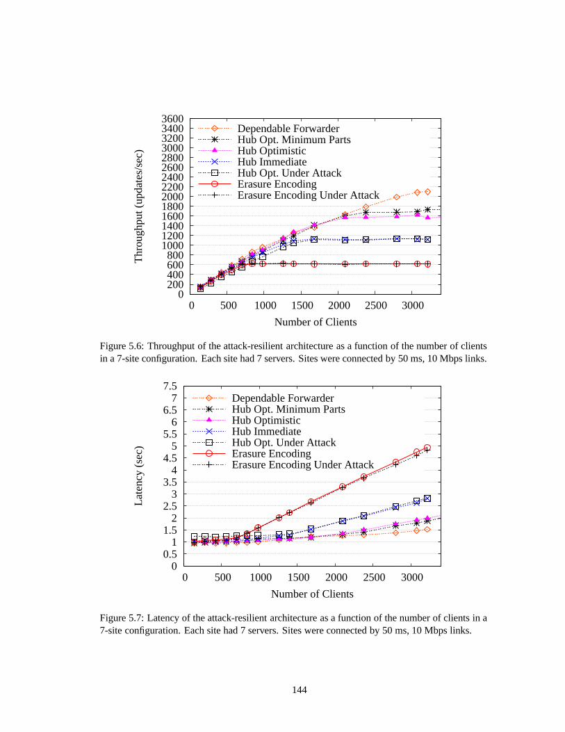
3600 3400 3200 3000 2800 2600 2400 2200 2000 1800 1600 1400 1200 1000 800 600 400 200
0 0 500 1000 1500 2000 2500 3000
Thr
ough
put (
upda
tes/
sec)
Number of Clients
Dependable ForwarderHub Opt. Minimum PartsHub OptimisticHub ImmediateHub Opt. Under AttackErasure EncodingErasure Encoding Under Attack
Figure 5.6: Throughput of the attack-resilient architecture as a function of the number of clientsin a 7-site configuration. Each site had 7 servers. Sites wereconnected by 50 ms, 10 Mbps links.
7.5 7
6.5 6
5.5 5
4.5 4
3.5 3
2.5 2
1.5 1
0.5 0
0 500 1000 1500 2000 2500 3000
Late
ncy
(sec
)
Number of Clients
Dependable ForwarderHub Opt. Minimum PartsHub OptimisticHub ImmediateHub Opt. Under AttackErasure EncodingErasure Encoding Under Attack
Figure 5.7: Latency of the attack-resilient architecture as a function of the number of clients in a7-site configuration. Each site had 7 servers. Sites were connected by 50 ms, 10 Mbps links.
144
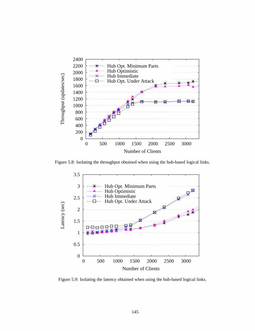
2400 2200 2000 1800 1600 1400 1200 1000 800 600 400 200
0 0 500 1000 1500 2000 2500 3000
Thr
ough
put (
upda
tes/
sec)
Number of Clients
Hub Opt. Minimum PartsHub OptimisticHub ImmediateHub Opt. Under Attack
Figure 5.8: Isolating the throughput obtained when using the hub-based logical links.
3.5
3
2.5
2
1.5
1
0.5
0 0 500 1000 1500 2000 2500 3000
Late
ncy
(sec
)
Number of Clients
Hub Opt. Minimum PartsHub OptimisticHub ImmediateHub Opt. Under Attack
Figure 5.9: Isolating the latency obtained when using the hub-based logical links.
145
Discussion: Our results demonstrate two main points. First, the logicallinks are effective in
mitigating performance attacks on the hierarchical architecture’s inter-site communication, while
still allowing reasonable fault-free and under-attack performance by using wide-area bandwidth
efficiently. Second, making slightly stronger assumptionsabout the resources available for building
a logical link can significantly improve performance. A simple broadcast hub can yield fault-free
performance close to the performance achieved when a dependable forwarder sends parts on behalf
of the site. Even when under attack, the peak throughput of the hub-based logical link only degrades
by between 30 and 40 percent, while resulting in a relativelysmall increase in latency.
Attacks on a flat deployment of Prime (whose effects were shown in Section 4.6) can be mounted
against both levels of the hierarchy. In one attack, a faultyleader can add at most two message
delays, plus an aggregation delay. In another attack, the faulty servers can cause the correct servers
to consume bandwidth for message reconciliation. When the delay attack is mounted in the local
site, the logical machine processing time increases by a delay whose duration is dominated by
the aggregation constant (30 ms in our implementation). Since local bandwidth is plentiful, the
reconciliation attacks do not have a significant impact on performance within the local site. The
same attacks can be mounted on the wide area and have an impactsimilar to when they are mounted
against physical machines. The attacks can decrease throughput by approximately a factor of 2 and
can increase update latency by two wide-area message delaysplus an aggregation constant (roughly
200ms in our implementation).
5.8 Attack-Resilient Architecture Summary
This chapter presented an attack-resilient architecture for large-scale intrusion-tolerant repli-
cation. We described three logical link protocols for efficient, attack-resilient inter-site commu-
nication, and we considered the practical and theoretical implications of deploying different state
146
machine replication protocols in the hierarchical architecture. Our experimental results showed
the performance benefits that can be realized by making slightly stronger assumptions about one’s
environment, without making it easier for faulty servers tocause inconsistency.
147

Chapter 6
Conclusions
Intrusion-tolerant replication is a promising tool for building a survivable critical infrastruc-
ture capable of remaining available even in the face of machine compromises. Prior to this work,
intrusion-tolerant replication protocols were designed to perform well (and were evaluated) in fault-
free executions. In this dissertation we pointed out that inmany systems, a small number of Byzan-
tine processors can degrade performance to a level far belowwhat would be achievable with only
correct processors. We presented the first intrusion-tolerant replication systems capable of making
a meaningful performance guarantee even when some of the processors are Byzantine.
We proposed a new, performance-oriented correctness criterion, BOUNDED-DELAY , for evalu-
ating intrusion-tolerant replication protocols. Protocols that meetBOUNDED-DELAY are required to
provide consistent performance in all executions, whetheror not there are actually Byzantine faults.
We presented Prime, a new intrusion-tolerant replication protocol that meetsBOUNDED-DELAY .
Prime bounds the amount of performance degradation that canbe caused by a malicious leader by
effectively monitoring its performance. This monitoring is enabled by requiring the leader to do an
amount of work bounded as a function of the number of servers in the system and independent of
the offered load.
148
We also presented an attack-resilient architecture for large-scale intrusion-tolerant replication
over wide-area networks. The attack-resilient architecture is hierarchical and uses Prime as a build-
ing block in each site and on the wide-area network. We presented three logical link protocols for
efficient, attack-resilient inter-site communication. Our experimental results provide evidence that
it is possible to construct a large-scale wide-area replication system that performs well under attack,
representing an important step towards being able to construct practical critical systems capable of
surviving partial compromises.
In the body of this dissertation, we focused on intrusion-tolerant replication protocols that rely
on a leader for coordination. In Appendix A, we give some evidence that performance attacks may
also be possible against decentralized protocols that do not use a leader.
149
Bibliography
[1] The BFT Project Homepage,http://www.pmg.csail.mit.edu/bft .
[2] Cauchy-based Reed Solomon Codes,http://www.icsi.berkeley.edu/ ˜ luby/
cauchy.tar.uu .
[3] Ciphertrust’s zombie statistics, http://www.ciphertrust.com/resources/
statistics/zombie.php .
[4] Genesis: A framework for achieving component diversity, http://www.cs.virginia.
edu/genesis/ .
[5] The netem Utility, http://www.linuxfoundation.org/collaborate/
workgroups/networking/netem .
[6] The OpenSSL Project,http://www.openssl.org .
[7] The OpenTC Library,http://projects.cerias.purdue.edu/ds2 .
[8] Securing Cyberspace: Efforts to Protect National Information Infrastructures Continue to Face
Challenges. Hearings from the Subcommittee on Federal Financial Management, Government
Information, and International Security of the Senate Committee on Homeland Security and
Governmental Affairs, 109th Congress, 1st Sess. (July 19, 2005), testimony of Paul Skare,
Product Manager, Siemens Power Transmission and Distribution, Inc.
150
[9] The Spines Project,http://www.spines.org/ .
[10] M. Abd-El-Malek, G.R. Ganger, G.R. Goodson, M.K. Reiter, and J.J. Wylie. Fault-scalable
Byzantine fault-tolerant services. InProceedings of the 20th ACM Symposium on Operating
Systems Principles (SOSP ’05), pages 59–74, Brighton, UK, 2005.
[11] S. Aiyer, Lorenzo Alvisi, Allen Clement, Mike Dahlin, Jean-Philippe Martin, and Carl Porth.
BAR fault tolerance for cooperative services. InProceedings of the 20th ACM Symposium on
Operating Systems Principles (SOSP ’05), pages 45–58. ACM, 2005.
[12] Ofir Amir, Yair Amir, and Danny Dolev. A highly availableapplication in the Transis environ-
ment. InRevised Papers from a Workshop on Hardware and Software Architectures for Fault
Tolerance, pages 125–139, London, UK, 1994. Springer-Verlag.
[13] Y. Amir, D. Dolev, S. Kramer, and D. Malki. Transis: A communication subsystem for high
availability. In Proceedings of the 22nd Annual International Symposium on Fault Tolerant
Computing (FTCS ’92), pages 76–84, Boston, Massachusetts, 1992. IEEE Computer Society
Press.
[14] Y. Amir, L. E. Moser, P. M. Melliar-Smith, D. A. Agarwal,and P. Ciarfella. The Totem single-
ring ordering and membership protocol.ACM Trans. Comput. Syst., 13(4):311–342, 1995.
[15] Yair Amir. Replication Using Group Communication Over a Partitioned Network. PhD thesis,
The Hebrew University of Jerusalem, Jerusalem, Israel, 1995.
[16] Yair Amir, Brian Coan, Jonathan Kirsch, and John Lane. Customizable fault tolerance for
wide-area replication. InProceedings of the 26th IEEE International Symposium on Reliable
Distributed Systems (SRDS ’07), pages 66–80, Beijing, China, 2007.
151
[17] Yair Amir, Brian Coan, Jonathan Kirsch, and John Lane. Byzantine replication under attack.
In Proceedings of the 38th IEEE/IFIP International Conference on Dependable Systems and
Networks (DSN ’08), pages 197–206, Anchorage, AK, USA, June 2008.
[18] Yair Amir, Claudiu Danilov, Danny Dolev, Jonathan Kirsch, John Lane, Cristina Nita-Rotaru,
Josh Olsen, and David Zage. Steward: Scaling Byzantine fault-tolerant replication to wide
area networks.IEEE Transactions on Dependable and Secure Computing, 7(1):80–93, 2010.
[19] Yair Amir, Claudiu Danilov, Jonathan Kirsch, John Lane, Danny Dolev, Cristina Nita-Rotaru,
Josh Olsen, and David Zage. Scaling Byzantine fault-tolerant replication to wide area net-
works. In Proceedings of the 2006 International Conference on Dependable Systems and
Networks (DSN’06), pages 105–114, Philadelphia, PA, USA, June 2006.
[20] Yair Amir, Claudiu Danilov, and Jonathan Stanton. A lowlatency, loss tolerant architecture
and protocol for wide area group communication. InProceedings of the 30th Annual Interna-
tional Symposium on Fault Tolerant Computing (FTCS ’00), pages 327–336, 2000.
[21] A. Avizeinis. The N-Version approach to fault-tolerant software. IEEE Transactions of Soft-
ware Engineering, SE-11(12):1491–1501, December 1985.
[22] Michael Ben-Or. Another advantage of free choice (extended abstract): Completely asyn-
chronous agreement protocols. InProceedings of the 2nd Annual ACM Symposium on Princi-
ples of Distributed Computing (PODC ’83), pages 27–30, 1983.
[23] Alysson Bessani, Paulo Sousa, Miguel Correia, Nuno Ferreira Neves, and Paulo Verissimo.
The CRUTIAL way of critical infrastructure protection.IEEE Security and Privacy, 6(6):44–
51, Nov-Dec 2008.
152
[24] S. Blake, D. Black, M. Carlson, E. Davies, Z. Wang, and W.Weiss. RFC 2475: An architecture
for differentiated services, December 1998.
[25] Johannes Blomer, Malik Kalfane, Marek Karpinski, Richard Karp, Michael Luby, and David
Zuckerman. An XOR-Based erasure-resilient coding scheme.Technical Report TR-95-048,
International Computer Science Institute, August 1995.
[26] Gabriel Bracha. An asynchronous [(n - 1)/3]-resilientconsensus protocol. InProceedings of
the third annual ACM symposium on Principles of DistributedComputing (PODC ’84), pages
154–162, Vancouver, British Columbia, Canada, 1984.
[27] Francisco V. Brasileiro, Paul D. Ezhilchelvan, Santosh K. Shrivastava, Neil A. Speirs, and Sha
Tao. Implementing fail-silent nodes for distributed systems. IEEE Transactions on Computers,
45(11):1226–1238, 1996.
[28] Christian Cachin, Klaus Kursawe, and Victor Shoup. Random oracles in constantipole: Prac-
tical asynchronous Byzantine agreement using cryptography (extended abstract). InProceed-
ings of the nineteenth annual ACM symposium on Principles ofdistributed computing (PODC
’00), pages 123–132, Portland, Oregon, 2000.
[29] Christian Cachin and Jonathan A. Portiz. Secure intrusion-tolerant replication on the internet.
In Proceedings of the 2002 International Conference on Dependable Systems and Networks
(DSN ’02), pages 167–176, Bethesda, MD, USA, June 2002.
[30] Miguel Castro. Practical Byzantine Fault Tolerance. PhD thesis, Massachusetts Institute of
Technology, Cambridge, Massachusetts, 2001.
[31] Miguel Castro and Barbara Liskov. Practical byzantinefault tolerance and proactive recovery.
ACM Transactions on Computer Systems, 20(4):398–461, 2002.
153
[32] Byung-Gon Chun, Petros Maniatis, Scott Shenker, and John Kubiatowicz. Attested append-
only memory: Making adversaries stick to their word.SIGOPS Oper. Syst. Rev., 41(6):189–
204, 2007.
[33] A. Clement, H. Li, J. Napper, J-P Martin, L. Alvisi, and M. Dahlin. BAR primer. In38th An-
nual IEEE/IFIP International Conference on Dependable Systms and Networks (DSN), June
2008.
[34] Allen Clement, Edmund Wong, Lorenzo Alvisi, Mike Dahlin, and Mirco Marchetti. Making
Byzantine fault tolerant systems tolerate Byzantine faults. In NSDI’09: Proceedings of the
6th USENIX symposium on Networked systems design and implementation, pages 153–168,
Berkeley, CA, USA, 2009. USENIX Association.
[35] M. Correia, L. C. Lung, N. F. Neves, and P. Verıssimo. Efficient Byzantine-resilient reliable
multicast on a hybrid failure model. InProceedings of the 21st Symposium on Reliable Dis-
tributed Systems (SRDS ’02), pages 2–11, Suita, Japan, October 2002.
[36] Miguel Correia, Nuno Ferreira Neves, and Paulo Verıssimo. How to tolerate half less one
Byzantine nodes in practical distributed systems. InProceedings of the 23rd IEEE Interna-
tional Symposium on Reliable Distributed Systems (SRDS’04), pages 174–183, Florianpolis,
Brazil, 2004.
[37] James Cowling, Daniel Myers, Barbara Liskov, Rodrigo Rodrigues, and Liuba Shrira. HQ
replication: A hybrid quorum protocol for Byzantine fault tolerance. InProceedings of the 7th
Symposium on Operating Systems Design and Implementation (OSDI ’06), pages 177–190,
Seattle, WA, November 2006.
[38] Vadim Drabkin, Roy Friedman, and Alon Kama. Practical Byzantine group communication.
154
In Proceedings of the 26th IEEE International Conference on Distributed Computing Systems
(ICDCS ’06), page 36, Lisboa, Portugal, 2006.
[39] Cynthia Dwork, Nancy Lynch, and Larry Stockmeyer. Consensus in the presence of partial
synchrony.Journal of the ACM, 35(2):288–323, 1988.
[40] Paul Feldman. A practical scheme for non-interactive verifiable secret sharing. InProceedings
of the 28th Annual Symposium on Foundations of Computer Science, pages 427–437, Los
Angeles, CA, USA, October 1987. IEEE Computer Society.
[41] Michael J. Fischer, Nancy A. Lynch, and Michael S. Paterson. Impossibility of distributed
consensus with one faulty process.J. ACM, 32(2):374–382, 1985.
[42] Mark Hayden. The Ensemble System. Technical Report TR98-1662, Department of Computer
Science, Cornell University, January 1998.
[43] Maurice P. Herlihy and Jeannette M. Wing. Linearizability: A correctness condition for con-
current objects.ACM Trans. Program. Lang. Syst., 12(3):463–492, 1990.
[44] I. Keidar. A highly available paradigm for consistent object replication. Master’s thesis,
Institute of Computer Science, The Hebrew University of Jerusalem, Jerusalem, Israel, 1994.
[45] Idit Keidar and Danny Dolev. Efficient message orderingin dynamic networks. InProceedings
of the 15th ACM Symposium on Principles of Distributed Computing (PODC ’96), pages 68–
76, 1996.
[46] Kim Potter Kihlstrom, Louise E. Moser, and P. M. Melliar-Smith. The SecureRing protocols
for securing group communication. InProceedings of the IEEE 31st Hawaii International
Conference on System Sciences, volume 3, pages 317–326, Kona, Hawaii, January 1998.
155
[47] Ramakrishna Kotla, Lorenzo Alvisi, Mike Dahlin, AllenClement, and Edmund Wong.
Zyzzyva: Speculative Byzantine fault tolerance.ACM Trans. Comput. Syst., 27(4):1–39, 2009.
[48] Eileen Kowalski, Dawn Cappelli, and Andrew Moore. Insider threat study: Illicit cyber ac-
tivity in the information technology and telecommunications sector. Technical Report U.S.
Secret Service and Carnegie Mellon University CERT/Software Engineering Institute. Avail-
able online athttp://www.cert.org/archive/pdf/insiderthreat_it200 8.
pdf , 2008.
[49] Leslie Lamport. Time, clocks, and the ordering of events in a distributed system.Commun.
ACM, 21(7):558–565, 1978.
[50] Leslie Lamport. The part-time parliament.ACM Transactions on Computer Systems,
16(2):133–169, May 1998.
[51] Leslie Lamport. Paxos made simple.SIGACTN: SIGACT News (ACM Special Interest Group
on Automata and Computability Theory), 32:18–25, 2001.
[52] Leslie Lamport, Robert E. Shostak, and Marshall C. Pease. The Byzantine generals problem.
ACM Trans. Program. Lang. Syst., 4(3):382–401, 1982.
[53] Jinyuan Li and David Mazieres. Beyond one-third faultyreplicas in Byzantine fault tolerant
systems. InProceedings of the 4th USENIX Symposium on Networked Systems Design and
Implementation (NSDI ’07), pages 131–144, 2007.
[54] F. J. MacWilliams and N. J. A. Sloane.The theory of error correcting codes. North-Holland
Pub. Co., New York, New York, 1977.
[55] Yanhua Mao, Flavio P. Junqueira, and Keith Marzullo. Towards low latency state machine
156
replication for uncivil wide-area networks. InProceedings of the 5th Workshop on Hot Topics
in System Dependability (HotDep ’09), 2009.
[56] Jean-Philippe Martin and Lorenzo Alvisi. Fast Byzantine consensus.IEEE Transactions on
Dependable and Secure Computing, 3(3):202–215, 2006.
[57] Ralph Charles Merkle.Secrecy, authentication, and public key systems.PhD thesis, Stanford
University, 1979.
[58] Henrique Moniz, Nuno Ferreira Neves, Miguel Correia, and Paulo Verıssimo. Randomized
intrusion-tolerant asynchronous services. InProceedings of the 2006 International Conference
on Dependable Systems and Networks (DSN’06), pages 568–577, 2006.
[59] Louise E. Moser, Yair Amir, P. Michael Melliar-Smith, and Deborah A. Agarwal. Extended
virtual synchrony. InProceedings of the 14th IEEE International Conference on Distributed
Computing Systems (ICDCS ’94), pages 56–65, 1994.
[60] Priya Narasimhan, Kim Potter Kihlstrom, Louise E. Moser, and P. M. Melliar-Smith. Pro-
viding support for survivable CORBA applications with the Immune system. InProceedings
of the 19th IEEE International Conference on Distributed Computing Systems (ICDCS ’99),
pages 507–516, Austin, TX, USA, 1999.
[61] Anh Nguyen-Tuong, David Evans, John C. Knight, Benjamin Cox, and Jack W. Davidson.
Security through redundant data diversity. InProceedings of the 38th Annual IEEE/IFIP In-
ternational Conference on Dependable Systems and Networks(DSN ’08), pages 187–196, June
2008.
[62] Brian M. Oki and Barbara H. Liskov. Viewstamped Replication: A new primary copy method
to support highly-available distributed systems. InProceedings of the seventh annual ACM
157
Symposium on Principles of distributed computing (PODC ’88), pages 8–17, New York, NY,
USA, 1988. ACM.
[63] Radia Perlman. Network Layer Protocols with Byzantine Robustness. PhD thesis, Mas-
sachusetts Institute of Technology, Cambridge, Massachusetts, 1988.
[64] D. Powell, D. Seaton, G. Bonn, P. Verıssimo, and F. Waeselynck. The Delta-4 approach
to dependability in open distributed computing systems. InProceedings of the 18th IEEE
International Symposium on Fault-Tolerant Computing (FTCS), pages 246–251, June 1988.
[65] M. O. Rabin. Randomized Byzantine generals. InThe 24th Annual IEEE Symposium on
Foundations of Computer Science, pages 403–409, 1983.
[66] Marisa Reddy Randazzo, Michelle Keeney, Eileen Kowalski, Dawn Cappelli, and Andrew
Moore. Insider threat study: Illicit Cyber Activity in the Banking and Finance Sector. Tech-
nical Report U.S. Secret Service and Carnegie Mellon University CME/SEI-2004-TR-021.
Available online athttp://www.sei.cmu.edu/library/abstracts/reports/
04tr021.cfm , 2005.
[67] Michael K. Reiter. Secure agreement protocols: Reliable and atomic group multicast in Ram-
part. InIn Proceedings of the 2nd ACM Conference on Computer and Communications Secu-
rity, pages 68–80. ACM, 1994.
[68] Michael K. Reiter. The Rampart Toolkit for building high-integrity services. InSelected
Papers from the International Workshop on Theory and Practice in Distributed Systems, pages
99–110, London, UK, 1995. Springer-Verlag.
[69] R. L. Rivest, A. Shamir, and L. Adleman. A method for obtaining digital signatures and
public-key cryptosystems.Commun. ACM, 21(2):120–126, 1978.
158
[70] Rodrigo Rodrigues, Miguel Castro, and Barbara Liskov.BASE: Using abstraction to improve
fault tolerance. InProceedings of the 18th ACM symposium on Operating systems principles
(SOSP ’01), pages 15–28, Banff, Alberta, Canada, 2001.
[71] Rodrigo Rodrigues, Petr Kouznetsov, and Bobby Bhattacharjee. Large-scale Byzantine fault
tolerance: Safe but not always live. InProceedings of the 3rd Workshop on Hot Topics in
System Dependability (HotDep ’07), page 17, 2007.
[72] Richard D. Schlichting and Fred B. Schneider. Fail-Stop Processors: An approach to designing
fault-tolerant computing systems.Computer Systems, 1(3):222–238, 1983.
[73] Fred B. Schneider. Implementing fault-tolerant services using the state machine approach: A
tutorial. ACM Computing Surveys, 22(4):299–319, 1990.
[74] Marco Serafini and Neeraj Suri. Reducing the costs of large-scale BFT replication. InPro-
ceedings of the 2nd Workshop on Large-Scale Distributed Systems and Middleware (LADIS
’08), pages 1–5, New York, NY, USA, 2008. ACM.
[75] Peter Shipley and Simson L. Garfinkel. An analysis of dial-up modems and vulnerabilities.
Available online athttp://simson.net/clips/academic/2001.Wardial.pdf ,
2001.
[76] Victor Shoup. Practical threshold signatures.Lecture Notes in Computer Science, 1807:207–
220, 2000.
[77] Atul Singh, Tathagata Das, Petros Maniatis, Peter Druschel, and Timothy Roscoe. BFT proto-
cols under fire. InProceedings of the 5th USENIX Symposium on Networked Systems Design
and Implementation (NSDI ’08), pages 189–204, 2008.
159
[78] The Boeing Company. Survivable Spread: Algorithms andassurance argument. Technical
Report Number D950-10757-1, July 2003.
[79] P. Verıssimo, N.F. Neves, C. Cachin, J. Poritz, D. Powell, Y. Deswarte, R. Stroud, and I. Welch.
Intrusion-tolerant middleware: The road to automatic security. IEEE Security & Privacy,
4(4):54–62, 2006.
[80] P. E. Verıssimo, N. F. Neves, and M. P. Correia. Intrusion-tolerant architectures: Concepts
and design. In R. Lemos, C. Gacek, and A. Romanovsky, editors, Architecting Dependable
Systems, volume 2677. 2003.
[81] Paulo Verıssimo. Travelling through wormholes: A newlook at distributed systems models.
SIGACT News, 37(1):66–81, 2006.
[82] Giuliana Santos Veronese, Miguel Correia, Alysson Neves Bessani, and Lau Cheuk Lung.
Highly resilient services for critical infrastructures. In Proceedings of the Embedded Systems
and Communications Security workshop (ESCS ’09), 2009.
[83] Giuliana Santos Veronese, Miguel Correia, Alysson Neves Bessani, and Lau Cheuk Lung.
Spin one’s wheels? Byzantine fault tolerance with a spinning primary. InProceedings of the
28th International Symposium on Reliable Distributed Systems (SRDS ’09), 2009.
[84] J. Yin, J.-P. Martin, A. Venkataramani, L. Alvisi, and M. Dahlin. Separating agreement from
execution for Byzantine fault-tolerant services. InProceedings of the 19th ACM Symposium
on Operating Systems Principles (SOSP ’03), pages 253–267, Bolton Landing, NY, USA,
October 2003.
160
Appendix A
Design of an Attack on a Decentralized
Intrusion-Tolerant Replication Protocol
This dissertation focused on the design of leader-based intrusion-tolerant replication protocols
that could resist performance failures and guarantee good performance as long as the network is
sufficiently stable. In this appendix we consider the problem of performance under attack in ade-
centralizedintrusion-tolerant replication protocol, which does not rely on a leader for coordination
and which requires no synchrony in the entire system to guarantee liveness (with probability 1).
In existing leader-based protocols, it is relatively easy to see how to design an attack that can be
effective in slowing down performance; since throughput depends on how fast the leader proposes
an ordering, one straightforward way to degrade performance is to slow down the leader. It is more
difficult to see how to degrade performance in decentralizedprotocols, and for this reason they are
generally believed to be harder to attack than leader-basedprotocols.
This appendix explores the feasibility of designing an attack that can be effective in reducing
performance in the RITAS atomic broadcast protocol [58], a decentralized intrusion-tolerant proto-
col that can be used for state machine replication. The attack has a somewhat theoretical flavor, and
161
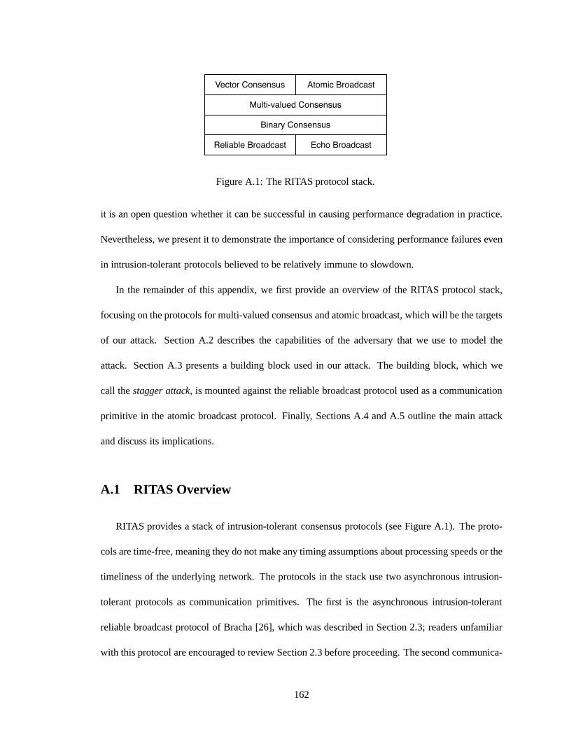
Reliable Broadcast Echo Broadcast
Binary Consensus
Multi-valued Consensus
Vector Consensus Atomic Broadcast
Figure A.1: The RITAS protocol stack.
it is an open question whether it can be successful in causingperformance degradation in practice.
Nevertheless, we present it to demonstrate the importance of considering performance failures even
in intrusion-tolerant protocols believed to be relativelyimmune to slowdown.
In the remainder of this appendix, we first provide an overview of the RITAS protocol stack,
focusing on the protocols for multi-valued consensus and atomic broadcast, which will be the targets
of our attack. Section A.2 describes the capabilities of theadversary that we use to model the
attack. Section A.3 presents a building block used in our attack. The building block, which we
call thestagger attack, is mounted against the reliable broadcast protocol used asa communication
primitive in the atomic broadcast protocol. Finally, Sections A.4 and A.5 outline the main attack
and discuss its implications.
A.1 RITAS Overview
RITAS provides a stack of intrusion-tolerant consensus protocols (see Figure A.1). The proto-
cols are time-free, meaning they do not make any timing assumptions about processing speeds or the
timeliness of the underlying network. The protocols in the stack use two asynchronous intrusion-
tolerant protocols as communication primitives. The first is the asynchronous intrusion-tolerant
reliable broadcast protocol of Bracha [26], which was described in Section 2.3; readers unfamiliar
with this protocol are encouraged to review Section 2.3 before proceeding. The second communica-
162
tion primitive is anecho broadcastprotocol, which is similar to the reliable broadcast protocol but
with the last round removed. The protocols requireN ≥ 3f + 1 processors to toleratef Byzantine
faults.
In order to circumvent the FLP impossibility result, the protocol at the bottom of the stack, a
binary consensusprotocol, makes use of randomization. The rest of the protocols in the stack are
deterministic but ultimately use the binary consensus protocol as a subroutine.
In binary consensus, each processor proposes an input from{0, 1}, and the protocol guarantees
that (1) all correct processors decide on the same value from{0, 1}, and (2) if all correct processors
propose the same value, then that value is the common decision. While we do not describe the
details of the binary consensus protocol here, we make note of one additional important property: If
all correct processors propose valuev, then all correct processors will decidev in a single iteration
of the protocol (i.e., in the minimum number of rounds). Thisproperty of guaranteeing termination
when the correct processors’ inputs are sufficiently homogeneous is shared by the multi-valued
consensus protocol, which is used by the atomic broadcast protocol that we ultimately wish to
attack. The property implies that an attack must cause at least some divergence in the correct
processors’ inputs to multi-valued consensus to have any chance of success.
As our attack primarily focuses on themulti-valued consensusandatomic broadcastprotocols,
we briefly review them now.
Multi-valued Consensus:The multi-valued consensus (MVC) protocol builds on a solution to
binary consensus to allow a set of processors to agree on a value from an arbitrary domain, rather
than simply from{0, 1}. Each processor proposes an input value, and the protocol either decides
on one of the processors’ input values or on a default value,⊥.
Upon invoking an instance of the protocol, a processor reliably broadcasts anMVC-INIT mes-
sage containing its input value. Upon reliably deliveringN − f MVC-INIT messages, a processor
163
computes a value,w, based on the messages it received. If at leastN−2f of the messages contained
identical values,v, thenw is set tov. Otherwise,w is set to⊥. The processor then echo broadcasts
its w value in anMVC-VECT message.
When a processor collectsN − f MVC-VECT messages, it chooses an input to binary consensus
based on the contents of theMVC-VECT messages. If the processor did not receive twoMVC-VECT
messages with different values, and if it received at leastN − 2f messages with the same value,
then it proposes a 1 to binary consensus; otherwise, it proposes 0. If binary consensus returns 0,
then MVC returns⊥. Otherwise, MVC returns the decided upon value. Like binaryconsensus,
MVC has the important property that if all correct processors propose the same input value, then
the protocol is guaranteed to decide that value in the minimum number of rounds.
Atomic Broadcast: In the RITAS atomic broadcast protocol, processors atomically broadcast
messages such that all correct processors atomically deliver the same set of messages in the same
order. The protocol uses a solution to multi-valued consensus as a subroutine.
To atomically broadcast a message, a processor reliably broadcasts it in anA-MSG message.
Each processor,i, maintains a set,R deliveredi, containing the messages thati has reliably delivered
but has not yet atomically delivered. When this set becomes non-empty,i reliably broadcasts an
A-VECT message, which contains the message identifiers of the messages inR deliveredi. Upon
reliably deliveringN − f A-VECT messages, processori generates a set,Wi, containing the set of
identifiers of messages that appeared in at leastf +1 of theN−f A-VECT messages. The processor
proposesWi as its input to an instance of MVC.
If MVC returns a non-default value,W , then the messages with identifiers inW can be atom-
ically delivered in some deterministic order. If MVC returns ⊥, then no messages are ready for
atomic delivery; since a processor’sR deliveredset is still non-empty, it will start a new iteration
of atomic broadcast by sending anA-VECT message. The set of message identifiers in thisA-VECT
164
message is a superset of the set of message identifiers in the previous, failed iteration of atomic
broadcast. In order to bound the number of times that MVC can return⊥, RITAS uses a window
mechanism whereby the identifiers of only the nextWINDOW undelivered messages from each pro-
cessor can be added to theA-VECT message. This helps the protocol terminate because eventually
all correct processors converge to the same inputs for MVC, in which case they will all propose 1
to binary consensus and the atomic broadcast protocol will make progress.
A.2 Designing an Adversary
As noted above, when correct processors all propose the sameinput value to MVC, there is
nothing the faulty processors can do to delay the protocol from completing successfully in the
minimum number of rounds. Whether or not the correct processors propose the same input to MVC
depends on the order in which they reliably deliver theA-MSG andA-VECT messages. Experimental
results (see [58]) indicate that on local-area networks, infault-free configurations, correct processors
are in fact likely to all propose the same value to MVC.
The preceding discussion implies that in order to cause performance degradation in the atomic
broadcast protocol, an attacker must cause at least some divergence in the correct processors’ inputs
to the multi-valued consensus protocol. To determine if such an attack is possible, we must consider
what type of attack the adversary is capable of mounting. Astrong network adversarycapable of
controlling the order in which messages are delivered to correct processors can cause divergence in
the MVC inputs by causing some correct processors to see a value f + 1 times and other correct
processors to see a value fewer thanf + 1 times. However, such a strong adversary may not reflect
the types of attacks that can actually be mounted in practice; indeed, such a strong adversary could
likely block progress altogether by severing the communication links between correct processors.
Our attack on the RITAS atomic broadcast protocol requires aweaker adversary, which we now
165
define. Our adversary does not have complete control over message delivery orderings. Rather, it
only controls (1) when the faulty processors send their messages and (2) to which processors the
faulty processors send their messages. We assume that faulty processors are capable of coordinating
their attacks. While the RITAS protocols are time-free, thenetwork on which they are deployed may
actually be highly synchronous, especially in a local-areanetwork setting where message delays are
symmetric and timing is predictable. We design our adversary to take advantage of these strong
timing properties. To simplify the analysis, we assume thatour adversary has precise knowledge of
the network and processing delays. As explained below, we believe a weaker adversary for which
this assumption is relaxed may still have the potential to mount an effective attack.
A.3 A Building Block: The Stagger Attack
This section describes a simple attack, which we refer to as the stagger attack, on Bracha’s
reliable broadcast protocol (see Algorithm 1 for pseudocode of the reliable broadcast protocol).
The stagger attack has the modest goal of staggering the reliable delivery, at correct processors, of
messages reliably broadcast by faulty processors. Specifically, the faulty processors can collude to
cause some correct processors to reliably deliver a messageafter three message delays and other
correct processors to reliably deliver the same message after four message delays.
Each faulty processor divides the2f + 1 correct processors into two groups,A andB, where
|A| = f +1 and|B| = f . A faulty processor also chooses atarget setof servers,T , whose members
will reliably deliver the faulty processor’s message in three message delays. Those servers not in the
target set will reliably deliver the message after four message delays. In the description that follows,
we letC denote the set of all correct processors, and we letF denote the set of faulty processors.
The stagger attack is summarized in Table A.1. When a faulty processor reliably broadcasts a
message,M , it sends anRB-INIT message only to the processors inF andA; the members ofB
166
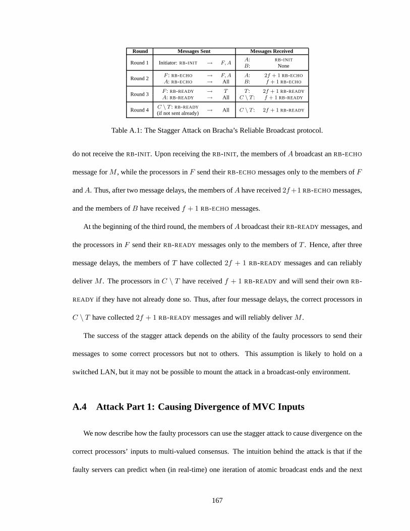
Round Messages Sent Messages Received
Round 1 Initiator: RB-INIT → F, AA: RB-INIT
B: None
Round 2F : RB-ECHO → F, A A: 2f + 1 RB-ECHO
A: RB-ECHO → All B: f + 1 RB-ECHO
Round 3F : RB-READY → T T : 2f + 1 RB-READY
A: RB-READY → All C \ T : f + 1 RB-READY
Round 4C \ T : RB-READY
→ All C \ T : 2f + 1 RB-READY(if not sent already)
Table A.1: The Stagger Attack on Bracha’s Reliable Broadcast protocol.
do not receive theRB-INIT . Upon receiving theRB-INIT , the members ofA broadcast anRB-ECHO
message forM , while the processors inF send theirRB-ECHO messages only to the members ofF
andA. Thus, after two message delays, the members ofA have received2f +1 RB-ECHOmessages,
and the members ofB have receivedf + 1 RB-ECHO messages.
At the beginning of the third round, the members ofA broadcast theirRB-READY messages, and
the processors inF send theirRB-READY messages only to the members ofT . Hence, after three
message delays, the members ofT have collected2f + 1 RB-READY messages and can reliably
deliverM . The processors inC \ T have receivedf + 1 RB-READY and will send their ownRB-
READY if they have not already done so. Thus, after four message delays, the correct processors in
C \ T have collected2f + 1 RB-READY messages and will reliably deliverM .
The success of the stagger attack depends on the ability of the faulty processors to send their
messages to some correct processors but not to others. This assumption is likely to hold on a
switched LAN, but it may not be possible to mount the attack ina broadcast-only environment.
A.4 Attack Part 1: Causing Divergence of MVC Inputs
We now describe how the faulty processors can use the staggerattack to cause divergence on the
correct processors’ inputs to multi-valued consensus. Theintuition behind the attack is that if the
faulty servers can predict when (in real-time) one iteration of atomic broadcast ends and the next
167
begins, they can trigger the stagger attack to begin so that the reliable delivery of a message spans
this boundary. Some correct processors (those in the targetset) will reliably deliver the message
before starting the new iteration of atomic broadcast; these processors will include the identifier
of the message in their nextA-VECT message. Those correct processors not in the target set will
reliably deliver the message after starting the new iteration of atomic broadcast and thus do not
include the message identifier in theirA-VECT message.
We now describe the attack in detail. A timeline of the attackis provided in Algorithm 5. In the
example that follows, we assume a system with 7 processors (i.e.,f = 2). Five of the processors
are correct (denotedC1 throughC5) and two of the processors are faulty (denotedF1 and F2).
ProcessorsF1 andF2 each atomically broadcast a message (M1 andM2, respectively) at the start
of the first round, which should be taken to mean the time at which they predict the attack should
commence if it is to be mounted successfully (i.e., so that the reliable delivery coincides with the
end of the current iteration of atomic broadcast).
Both faulty processors use the stagger attack, but they choose different target sets:
• F1 chooses a target set containingC1 andC2, causing them to deliverM1 at the start of Round
4; C3, C4, andC5 deliverM1 at the start of Round 5.
• F2 chooses a target set containingC3 andC4, causing them to deliverM2 at the start of round
4; C1, C2, andC5 deliverM2 at the start of round 5.
168
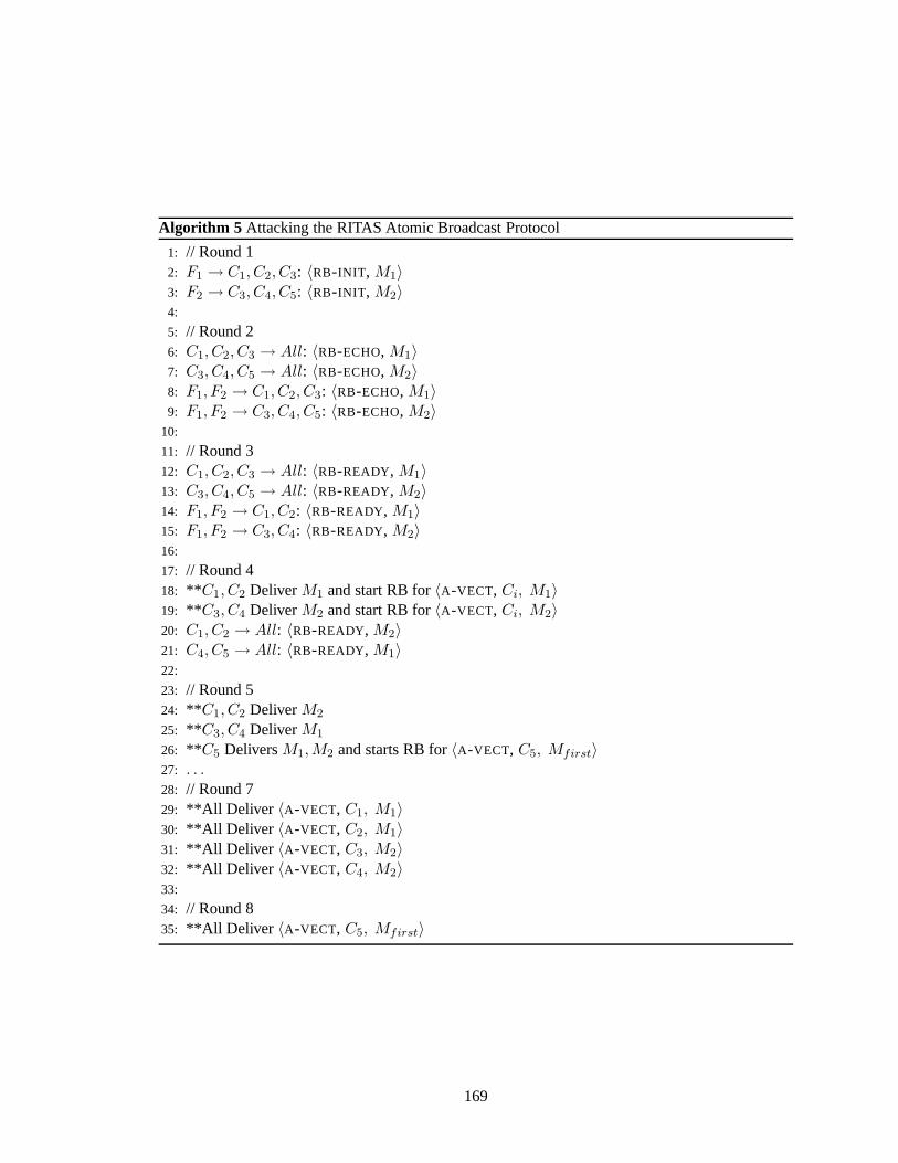
Algorithm 5 Attacking the RITAS Atomic Broadcast Protocol
1: // Round 12: F1 → C1, C2, C3: 〈RB-INIT , M1〉3: F2 → C3, C4, C5: 〈RB-INIT , M2〉4:
5: // Round 26: C1, C2, C3 → All: 〈RB-ECHO, M1〉7: C3, C4, C5 → All: 〈RB-ECHO, M2〉8: F1, F2 → C1, C2, C3: 〈RB-ECHO, M1〉9: F1, F2 → C3, C4, C5: 〈RB-ECHO, M2〉
10:
11: // Round 312: C1, C2, C3 → All: 〈RB-READY, M1〉13: C3, C4, C5 → All: 〈RB-READY, M2〉14: F1, F2 → C1, C2: 〈RB-READY, M1〉15: F1, F2 → C3, C4: 〈RB-READY, M2〉16:
17: // Round 418: ** C1, C2 DeliverM1 and start RB for〈A-VECT, Ci, M1〉19: ** C3, C4 DeliverM2 and start RB for〈A-VECT, Ci, M2〉20: C1, C2 → All: 〈RB-READY, M2〉21: C4, C5 → All: 〈RB-READY, M1〉22:
23: // Round 524: ** C1, C2 DeliverM2
25: ** C3, C4 DeliverM1
26: ** C5 DeliversM1,M2 and starts RB for〈A-VECT, C5, Mfirst〉27: . . .28: // Round 729: **All Deliver 〈A-VECT, C1, M1〉30: **All Deliver 〈A-VECT, C2, M1〉31: **All Deliver 〈A-VECT, C3, M2〉32: **All Deliver 〈A-VECT, C4, M2〉33:
34: // Round 835: **All Deliver 〈A-VECT, C5, Mfirst〉
169
When a processor reliably delivers its first message,Mi for i ∈ {1, 2}, it initiates the reliable
broadcast of anA-VECT message containingMi. Note that theA-VECT messages fromC1 andC2
containM1 but notM2, and theA-VECT messages fromC3 andC4 containM2 but notM1. The
A-VECT message fromC5 contains whichever message it reliably delivered first, denotedMfirst,
but not both (Algorithm 5, line 26).
TheA-VECT messages from processorsC1, C2, C3, andC4 will be reliably delivered at the start
of Round 7; the steps of these reliable broadcasts are not shown. TheA-VECT message fromC5 will
not be reliably delivered until Round 8. If the faulty processors sendA-VECT messages, they can
ensure the messages are reliably delivered by Round 7 by sending them in Round 4 (or by sending
them in Round 3 if the stagger attack is used).
Thus, at the start of Round 7, processorsC1, C2, C3, andC4 reliably deliver twoA-VECT mes-
sages containingM1 only, two A-VECT messages containingM2 only, and (if the faulty processors
sendA-VECT messages), twoA-VECT messages from the faulty processors. The key point to ob-
serve is that depending on how the faulty processors choose to send theirA-VECT messages, they
may be able to encourage divergence on which messages (out ofM1 andM2) appear inf +1 out of
the2f + 1 A-VECT messages used by correct processors to construct their input to MVC. We now
explain how this is possible.
If the faulty processors reliably broadcast theirA-VECT messages in Round 4 without the stagger
attack, then the number ofA-VECT messages that will be delivered in Round 7 forM1 andM2 are
equal (i.e., 3 and 3). Since a correct processor builds its input to MVC based on 5 messages, exactly
one ofM1 andM2 will be proposed as input. Assuming messages arriving in thesame round have an
equal probability of being delivered, a correct processor has an equal chance of proposingM1 only
andM2 only, meaning the correct processors are expected to be split roughly evenly betweenM1
andM2. This scenario is successful for the attacker, because it has at least created an opportunity
170
for MVC to run for longer than the minimum number of rounds.
The faulty processors can control the split of correct servers to a greater degree by using the
stagger attack on their ownA-VECT messages. If the faulty processors initiate the reliable broadcast
of their A-VECT messages in Round 3, then their messages will be reliably delivered beforeC5’s
A-VECT is delivered (Round 6 or 7 compared to Round 8). This allows the faulty processors to bias
the likelihood that a correct processor proposesM1 only orM2 only to MVC. To bias a set of correct
processors,S1, towardsM1, the faulty processors delay the delivery ofF2’s A-VECT message at the
members ofS1. Similarly, to bias a setS2 towardsM2, the faulty processors delay the delivery of
F1’s A-VECT message at the members ofS2. If S1 andS2 are about the same size, then using this
attack increases the likelihood of a roughly even split among the correct processors betweenM1
andM2.
Note that the faulty processors need to send conflictingA-VECT messages in order to cause
divergence. If they do not send anyA-VECT messages at all, then all correct processors will use
the same set of2f + 1 A-VECT messages to build their input to MVC (i.e., when they receiveC5’s
A-VECT message in Round 8). Therefore, all correct processors either proposeM1 only or M2
only, depending on the content ofC5’s message. Similarly, if the faulty processors sendA-VECT
messages with matching content in Round 4, for eitherM1 or M2 only, then all correct processors
will either proposeM1 only orM2 only to MVC, depending on which message the faulty processors
used.
As the number of faulty processors increases, the attacker has more power to split the correct
processors into multiple disjoint sets. Note that if no set of f + 1 correct processors proposes
the same input to MVC, then the atomic broadcast protocol will need to run for at least one more
iteration, increasing latency.
171
A.5 Attack Part 2: Pushing Multi-Valued Consensus Towards⊥
Assuming the faulty processors can cause divergent inputs to multi-valued consensus, we now
describe how they can push MVC towards deciding the default value,⊥. This delays the atomic
delivery of any messages for at least one more iteration of the atomic broadcast protocol.
We begin by supposing that the faulty processors caused the correct processors to be split
roughly in half between two input values,V1 andV2, whereV1 contains messageM1 but notM2, and
V2 contains messageM2 but notV1. Since there are2f +1 correct processors, we suppose (without
loss of generality) thatf + 1 correct processors proposedV1 and the otherf correct processors pro-
posedV2. If the faulty processors do not send any messages in the multi-valued consensus protocol,
then the correct processors will all decide onV1: they will all receivef + 1 MVC-INIT messages
for V1 andf MVC-INIT messages forV2, meaning they will all sendMVC-VECT messages forV1.
This demonstrates that the faulty processors need to send particular messages to have a chance at
causing delay.
We now describe how the faulty processors can encourage correct processors to sendMVC-VECT
messages containing the default value (⊥), rather than a real value, assuming the correct processors
are split as above. If most correct processors propose⊥, then MVC will likely return⊥, in which
case the upper-level atomic broadcast protocol will be forced to run again.
Since onlyf correct processors proposedV2, the faulty processors can preventV2 from being
sent in theMVC-VECT message of any correct processor simply by sendingMVC-INIT messages
containing any value other thanV2. This prevents MVC from returningV2.
Sincef + 1 correct processors proposedV1, a correct processor will only sendV1 in its MVC-
VECT message if the set of2f + 1 MVC-INIT messages that it collects contains all of thef + 1
MVC-INIT messages from the correct processors that proposedV1 (assuming the faulty processors
do not sendMVC-INIT messages proposingV1). If the faulty processors sendMVC-INIT messages
172
proposing some other value (sayV3), and messages reliably delivered in the same round are equally
likely to be delivered first, the attacker already has a reasonable chance that one of thef +1 needed
MVC-INIT messages will be among the lastf delivered in the round.
In fact, the attacker can increase its probability of success by starting the reliable broadcast of
the faulty processors’MVC-INIT messages early. Since the communication model is asynchronous,
a correct processor cannot “tell” that a faulty processor started its reliable broadcast early, but in
practice the message will be reliably delivered before messages sent at the “correct” time. Therefore,
with high likelihood, thef MVC-INIT messages from the faulty processors will be among the2f +1
considered messages. This means that a correct processor will propose⊥ unless the nextf + 1
MVC-INIT messages it delivers are exactly thef + 1 messages that proposedV1. Thus, the correct
processors are likely to sendMVC-VECT messages proposing⊥, in which case MVC will likely
return⊥ and no messages will be atomically delivered in this round ofthe atomic broadcast protocol.
Note that this attack can still be effective even if the correct processors are split less evenly. As
long as the number of correct processors whose inputs to MVC are identical is less than2f + 1, the
attack has some chance of succeeding, although with lower probability. As noted above, the window
mechanism used by the atomic broadcast protocol ensures that the correct processors eventually
converge to the same inputs for MVC, at which point all messages in the window will be atomically
delivered.
173
Vita
Jonathan Kirsch was born in 1982 on Long Island, New York. He received his B.S. in Computer
Science from Yale University in May 2004 and joined the Distributed Systems and Networks Lab
at Johns Hopkins University in August 2004. His research focused on building high performance,
survivable replication systems. He received his M.S.E. in Computer Science in 2007 and his Ph.D.
in Computer Science in 2010.
174