inverse procedural modeling by automatic …misha/readingseminar/papers/stava10.pdfo.Št’ava et....
TRANSCRIPT
EUROGRAPHICS 2010 / T. Akenine-Möller and M. Zwicker(Guest Editors)
Volume 29 (2010), Number 2
Inverse Procedural Modeling byAutomatic Generation of L-systems
O. Št’ava1, B. Beneš1, R. Mech2, D. G. Aliaga1 and P. Krištof1
1Purdue University, USA 2Adobe Systems Incorporated, USA
AbstractWe present an important step towards the solution of the problem of inverse procedural modeling by generatingparametric context-free L-systems that represent an input 2D model. The L-system rules efficiently code the regularstructures and the parameters represent the properties of the structure transformations. The algorithm takes asinput a 2D vector image that is composed of atomic elements, such as curves and poly-lines. Similar elements arerecognized and assigned terminal symbols of an L-system alphabet. The terminal symbols’ position and orientationare pair-wise compared and the transformations are stored as points in multiple 4D transformation spaces. Bycareful analysis of the clusters in the transformation spaces, we detect sequences of elements and code themas L-system rules. The coded elements are then removed from the clusters, the clusters are updated, and thenthe analysis attempts to code groups of elements in (hierarchies) the same way. The analysis ends with a singlegroup of elements that is coded as an L-system axiom. We recognize and code branching sequences of linearlytranslated, scaled, and rotated elements and their hierarchies. The L-system not only represents the input image,but it can also be used for various editing operations. By changing the L-system parameters, the image can berandomized, symmetrized, and groups of elements and regular structures can be edited. By changing the terminaland non-terminal symbols, elements or groups of elements can be replaced.
Categories and Subject Descriptors (according to ACM CCS): Mathematical Logic and Formal Languages [F.4.2]:Grammars and Other Rewriting Systems—Parallel rewriting systems - L-systems; Computer Graphics [I.3.5]:Computational Geometry and Object Modeling— Geometric algorithms, languages, and systems;
1. Introduction
We present an important step towards the solution ofthe problem of inverse procedural modeling. Procedu-ral techniques in computer graphics are commonly de-fined [EMP∗03] as algorithms that generate amodel, texture,or behavior. One of the most significant classes of procedu-ral techniques are grammar-based methods, out of which themost common are methods based on Lindenmayer’s systems(L-systems) [PL90]. L-systems use compact rules for modeldescription yet they can generate a wide class of models.
The key challenge of procedural techniques is the defini-tion of the rules. This task is not intuitive, lacks controlla-bility, requires in-depth knowledge of procedural modeling,and resembles programming in an advanced language. Auto-matic generation of procedural rules, or inverse proceduralmodeling, has been an open problem for more than 20 years.Its goal is to find the rules of a procedural system that would
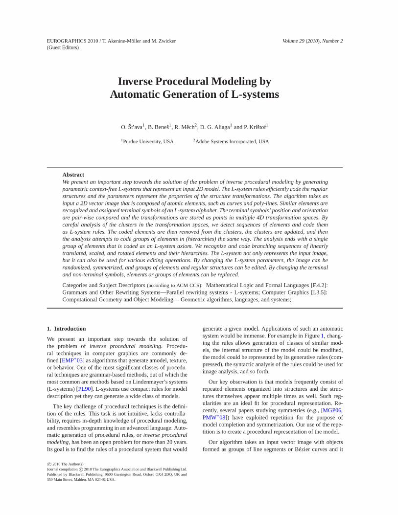
generate a given model. Applications of such an automaticsystem would be immense. For example in Figure 1, chang-ing the rules allows generation of classes of similar mod-els, the internal structure of the model could be modified,the model could be represented by its generative rules (com-pressed), the syntactic analysis of the rules could be used forimage analysis, and so forth.
Our key observation is that models frequently consist ofrepeated elements organized into structures and the struc-tures themselves appear multiple times as well. Such reg-ularities are an ideal fit for procedural representation. Re-cently, several papers studying symmetries (e.g., [MGP06,PMW∗08]) have exploited repetition for the purpose ofmodel completion and symmetrization. Our use of the repe-tition is to create a procedural representation of the model.
Our algorithm takes an input vector image with objectsformed as groups of line segments or Bézier curves and it
c© 2010 The Author(s)Journal compilation c© 2010 The Eurographics Association and Blackwell Publishing Ltd.Published by Blackwell Publishing, 9600 Garsington Road, Oxford OX4 2DQ, UK and350 Main Street, Malden, MA 02148, USA.
O.Št’ava et. al. / Inverse Procedural Modeling by Automatic Generation of L-systems
a) b)
c) d)
Figure 1: a) A branching structure with varying scaling isautomatically coded as an L-system. The basic element is aBézier curve (in red), the generated rule has form R(m) →A[−(17) f (64)∗(0.8)− (3)R(m−1)] [+(7) f (181)∗(0.6)+(23)R(m− 1)], and the axiom is R(3). b) A structure gen-erated using the detected rule from axiom R(10) and c) abranching structure generated from R(10) with randomizedangles and d) randomized angles and scaling.
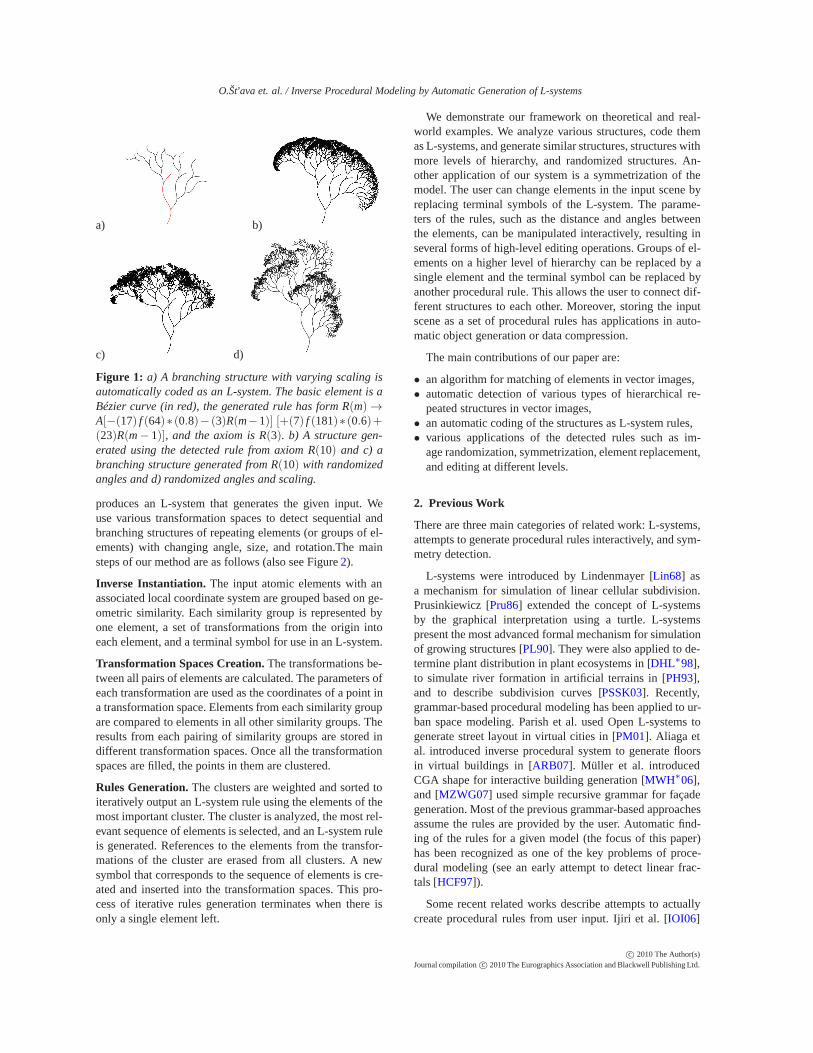
produces an L-system that generates the given input. Weuse various transformation spaces to detect sequential andbranching structures of repeating elements (or groups of el-ements) with changing angle, size, and rotation.The mainsteps of our method are as follows (also see Figure 2).
Inverse Instantiation. The input atomic elements with anassociated local coordinate system are grouped based on ge-ometric similarity. Each similarity group is represented byone element, a set of transformations from the origin intoeach element, and a terminal symbol for use in an L-system.
Transformation Spaces Creation. The transformations be-tween all pairs of elements are calculated. The parameters ofeach transformation are used as the coordinates of a point ina transformation space. Elements from each similarity groupare compared to elements in all other similarity groups. Theresults from each pairing of similarity groups are stored indifferent transformation spaces. Once all the transformationspaces are filled, the points in them are clustered.
Rules Generation. The clusters are weighted and sorted toiteratively output an L-system rule using the elements of themost important cluster. The cluster is analyzed, the most rel-evant sequence of elements is selected, and an L-system ruleis generated. References to the elements from the transfor-mations of the cluster are erased from all clusters. A newsymbol that corresponds to the sequence of elements is cre-ated and inserted into the transformation spaces. This pro-cess of iterative rules generation terminates when there isonly a single element left.
We demonstrate our framework on theoretical and real-world examples. We analyze various structures, code themas L-systems, and generate similar structures, structures withmore levels of hierarchy, and randomized structures. An-other application of our system is a symmetrization of themodel. The user can change elements in the input scene byreplacing terminal symbols of the L-system. The parame-ters of the rules, such as the distance and angles betweenthe elements, can be manipulated interactively, resulting inseveral forms of high-level editing operations. Groups of el-ements on a higher level of hierarchy can be replaced by asingle element and the terminal symbol can be replaced byanother procedural rule. This allows the user to connect dif-ferent structures to each other. Moreover, storing the inputscene as a set of procedural rules has applications in auto-matic object generation or data compression.
The main contributions of our paper are:
• an algorithm for matching of elements in vector images,• automatic detection of various types of hierarchical re-
peated structures in vector images,• an automatic coding of the structures as L-system rules,• various applications of the detected rules such as im-
age randomization, symmetrization, element replacement,and editing at different levels.
2. Previous Work
There are three main categories of related work: L-systems,attempts to generate procedural rules interactively, and sym-metry detection.
L-systems were introduced by Lindenmayer [Lin68] asa mechanism for simulation of linear cellular subdivision.Prusinkiewicz [Pru86] extended the concept of L-systemsby the graphical interpretation using a turtle. L-systemspresent the most advanced formal mechanism for simulationof growing structures [PL90]. They were also applied to de-termine plant distribution in plant ecosystems in [DHL∗98],to simulate river formation in artificial terrains in [PH93],and to describe subdivision curves [PSSK03]. Recently,grammar-based procedural modeling has been applied to ur-ban space modeling. Parish et al. used Open L-systems togenerate street layout in virtual cities in [PM01]. Aliaga etal. introduced inverse procedural system to generate floorsin virtual buildings in [ARB07]. Müller et al. introducedCGA shape for interactive building generation [MWH∗06],and [MZWG07] used simple recursive grammar for façadegeneration. Most of the previous grammar-based approachesassume the rules are provided by the user. Automatic find-ing of the rules for a given model (the focus of this paper)has been recognized as one of the key problems of proce-dural modeling (see an early attempt to detect linear frac-tals [HCF97]).
Some recent related works describe attempts to actuallycreate procedural rules from user input. Ijiri et al. [IOI06]
c© 2010 The Author(s)Journal compilation c© 2010 The Eurographics Association and Blackwell Publishing Ltd.
O.Št’ava et. al. / Inverse Procedural Modeling by Automatic Generation of L-systems
Figure 2: System pipeline: 1. Similar elements of the input image are detected and terminal symbols are generated for eachgroup of similar elements. 2. Pairwise transformations are calculated and transformation spaces are filled with points corre-sponding to each transformation. Mean shift clustering determines clusters of similarly oriented elements. 3. Cluster signif-icance is calculated based on user-defined criteria. 4. Groups of elements are represented as L-system rules. Each group isrepresented as a new non-terminal and the clusters in the transformations space that contain references to them are updated.The process ends with a single element that represents the axiom of the L-system.
used a sketch-based system to code user strokes as an L-system rule that is then used for an interactive plant gen-eration. However, more complex rules cannot be generatedand the system allows only for matching one predefined rule.Similarly Lipp et al. [LWW08] generate shape grammarsfrom user input. Again, in their system only a predefinedset of rules can be used. Ijiri et al. [IMIM08] introduced anexample-based framework for procedural element arrange-ment generation and recently [YM09] used transformationspaces to detect symmetries and curvilinear arrangement invector images. The above two user-assisted systems use sim-ple algorithms for procedural models generation and theycan express only a limited number of effects and a limitedclass of procedural models. The main difference between ourapproach and previous work is that we express the output us-ing automatically determined rules for an L-system.
Our work is inspired by the recent work on symmetry de-tection. Mitra et al. [MGP06] introduced algorithms for de-tecting symmetries in unstructured 3D models by selectingdominant transformations in a transformation space. Simi-lar concepts have since been used by others [LE06,PSG∗06,XZT∗09]. The model is sampled to create local signatures.The signatures are compared pairwise, and the results aremapped as points into the transformation space. As clustersof points correspond to potential symmetries, the clusters aredetected and the symmetries are stored in a symmetry graph.The next paper by the same authors [MGP07] uses the sym-metries to modify objects to express more symmetries thanthe originals. Pauly et al. [PMW∗08] presented a paper ondiscovering regular and repeated geometric structures. Theydetect scaling, rotation, translation, and the combination ofstructural elements in an input scene. The principal findingof this work is that repetitive structures present themselves asregularly spaced sets of clusters in the transformation space.Other techniques for symmetry detection focus on detect-
ing features by first connecting them into a graph and thenusing a RANSAC-based randomized subgraph searching al-gorithm [BBW∗08, BBW∗09]. We exploit the concept oftransformation spaces in our work, with the following dif-ferences. First, we do not use a single scene or a continuousobject. Instead our input scene is a set of atomic, orientedelements. This allows us to use a particular transformationspace for pairs of elements of specific types, resulting in littlenoise in each transformation space. Second, since our goalis the creation of L-system rules, the transformation spaceexploration is primarily driven by the desire to find the pro-cedural rules and goes beyond just discovering symmetries.Third, we explore subspaces of the transformation space todetect rotated, translated, and scaled sequences of repetitiveobjects. Finally, we update the transformation spaces by oneor multiple rules.
3. L-systems
We provide a brief description of L-systems and extensionsthat have been introduced for our purposes. Readers famil-iar with L-systems can skip this section keeping in mind thatthere are the following extensions: 1) we introduce scalingas a new command for the turtle, 2) the alphabet is dividedinto two groups of symbols: terminal and non-terminal sym-bols. Terminals are interpreted as turtle commands, and non-terminals are used in the rewriting process and 3) the ter-minal symbols are the standard turtle commands plus newsymbols that represent the elements from the input image.
Our L-system is defined as a tuple
G = 〈M,ω,�〉 , (1)
where M is the L-system alphabet that contains elements{A(p1, p2, . . . , pn),B(p1, p2, . . . , pm), . . .} called modules.Modules consist of the letters A,B, . . . and their parameters
c© 2010 The Author(s)Journal compilation c© 2010 The Eurographics Association and Blackwell Publishing Ltd.
O.Št’ava et. al. / Inverse Procedural Modeling by Automatic Generation of L-systems
p1, p2, . . . pn ∈ R. The symbol ω ∈ M+ (M+ denotes the re-flexive closure) is a non-empty initial string of modules (ax-iom). Finally, � is a set of productions (rules)
label : A(p0, p1, . . . , pn) : cond → A∗,
where label is the production identifier, cond is a Booleanexpression involving the parameters, and M∗ denotes thereflexive-transitive closure i.e., the list of all strings includ-ing the empty string ε. The symbol → denotes rewriting ofthe module A(p0, p1, . . . , pn) with the string on the right sideof the rule. We drop the label if the rule is not reused.
The implicit rule for rewriting a single module is:
r0 : A(p0, p1, . . . , pn)→ A(p0, p1, . . . , pn), (2)
and it rewrites a module with its exact copy. This is appliedwhen there is no corresponding rule in � for a module fromM. The epsilon rule erases the symbol A(p0, p1, . . . , pn):
rε : A(p0, p1, . . . , pn)→ ε. (3)
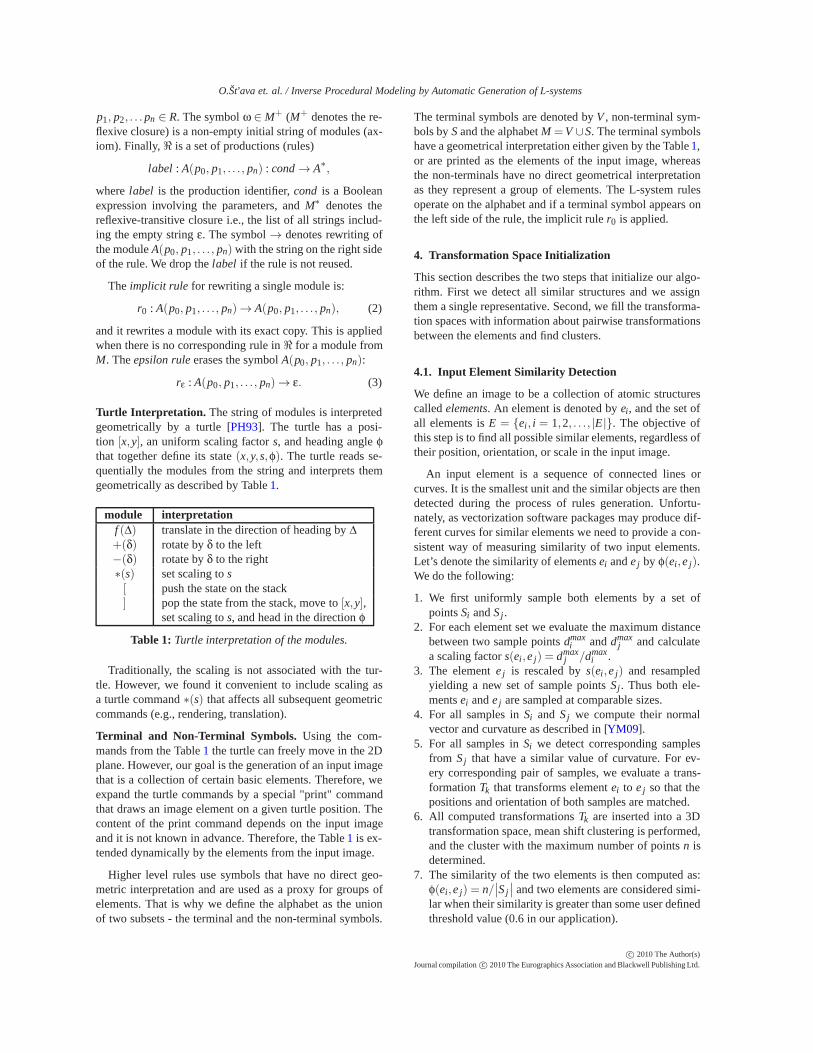
Turtle Interpretation. The string of modules is interpretedgeometrically by a turtle [PH93]. The turtle has a posi-tion [x,y], an uniform scaling factor s, and heading angle φthat together define its state (x,y, s,φ). The turtle reads se-quentially the modules from the string and interprets themgeometrically as described by Table 1.
module interpretationf (Δ) translate in the direction of heading by Δ+(δ) rotate by δ to the left−(δ) rotate by δ to the right∗(s) set scaling to s[ push the state on the stack] pop the state from the stack, move to [x,y],
set scaling to s, and head in the direction φ
Table 1: Turtle interpretation of the modules.
Traditionally, the scaling is not associated with the tur-tle. However, we found it convenient to include scaling asa turtle command ∗(s) that affects all subsequent geometriccommands (e.g., rendering, translation).
Terminal and Non-Terminal Symbols. Using the com-mands from the Table 1 the turtle can freely move in the 2Dplane. However, our goal is the generation of an input imagethat is a collection of certain basic elements. Therefore, weexpand the turtle commands by a special "print" commandthat draws an image element on a given turtle position. Thecontent of the print command depends on the input imageand it is not known in advance. Therefore, the Table 1 is ex-tended dynamically by the elements from the input image.
Higher level rules use symbols that have no direct geo-metric interpretation and are used as a proxy for groups ofelements. That is why we define the alphabet as the unionof two subsets - the terminal and the non-terminal symbols.
The terminal symbols are denoted by V , non-terminal sym-bols by S and the alphabet M =V ∪S. The terminal symbolshave a geometrical interpretation either given by the Table 1,or are printed as the elements of the input image, whereasthe non-terminals have no direct geometrical interpretationas they represent a group of elements. The L-system rulesoperate on the alphabet and if a terminal symbol appears onthe left side of the rule, the implicit rule r0 is applied.
4. Transformation Space Initialization
This section describes the two steps that initialize our algo-rithm. First we detect all similar structures and we assignthem a single representative. Second, we fill the transforma-tion spaces with information about pairwise transformationsbetween the elements and find clusters.
4.1. Input Element Similarity Detection
We define an image to be a collection of atomic structurescalled elements. An element is denoted by ei, and the set ofall elements is E = {ei, i = 1,2, . . ., |E|}. The objective ofthis step is to find all possible similar elements, regardless oftheir position, orientation, or scale in the input image.
An input element is a sequence of connected lines orcurves. It is the smallest unit and the similar objects are thendetected during the process of rules generation. Unfortu-nately, as vectorization software packages may produce dif-ferent curves for similar elements we need to provide a con-sistent way of measuring similarity of two input elements.Let’s denote the similarity of elements ei and e j by φ(ei,e j).We do the following:
1. We first uniformly sample both elements by a set ofpoints Si and Sj .
2. For each element set we evaluate the maximum distancebetween two sample points dmax
i and dmaxj and calculate
a scaling factor s(ei,e j) = dmaxj /dmax
i .3. The element e j is rescaled by s(ei,e j) and resampled
yielding a new set of sample points Sj . Thus both ele-ments ei and e j are sampled at comparable sizes.
4. For all samples in Si and Sj we compute their normalvector and curvature as described in [YM09].
5. For all samples in Si we detect corresponding samplesfrom S j that have a similar value of curvature. For ev-ery corresponding pair of samples, we evaluate a trans-formation Tk that transforms element ei to e j so that thepositions and orientation of both samples are matched.
6. All computed transformations Tk are inserted into a 3Dtransformation space, mean shift clustering is performed,and the cluster with the maximum number of points n isdetermined.
7. The similarity of the two elements is then computed as:φ(ei,e j) = n/
∣∣S j
∣∣ and two elements are considered simi-
lar when their similarity is greater than some user definedthreshold value (0.6 in our application).
c© 2010 The Author(s)Journal compilation c© 2010 The Eurographics Association and Blackwell Publishing Ltd.
O.Št’ava et. al. / Inverse Procedural Modeling by Automatic Generation of L-systems
The result of this step is a unique ID that identifies ele-ments that are visually similar independently on their ori-entation, position, and scaling. The result depends on thechoice of the similarity threshold and can fail for highly dis-similar inputs.
4.2. Terminal Symbols by Inverse Instancing
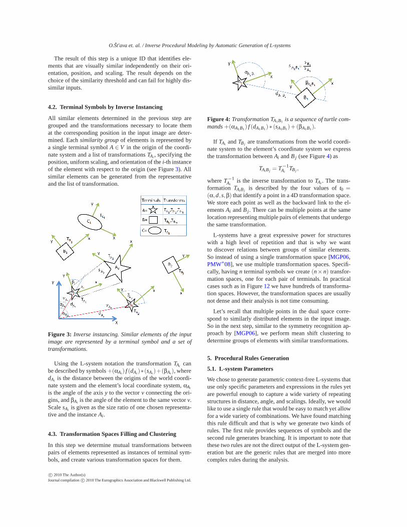
All similar elements determined in the previous step aregrouped and the transformations necessary to locate themat the corresponding position in the input image are deter-mined. Each similarity group of elements is represented bya single terminal symbol A ∈ V in the origin of the coordi-nate system and a list of transformations TAi , specifying theposition, uniform scaling, and orientation of the i-th instanceof the element with respect to the origin (see Figure 3). Allsimilar elements can be generated from the representativeand the list of transformation.
Figure 3: Inverse instancing. Similar elements of the inputimage are represented by a terminal symbol and a set oftransformations.
Using the L-system notation the transformation TAi canbe described by symbols +(αAi) f (dAi)∗(sAi )+(βAi), wheredAi is the distance between the origins of the world coordi-nate system and the element’s local coordinate system, αAi
is the angle of the axis y to the vector v connecting the ori-gins, and βAi is the angle of the element to the same vector v.Scale sAi is given as the size ratio of one chosen representa-tive and the instance Ai.
4.3. Transformation Spaces Filling and Clustering
In this step we determine mutual transformations betweenpairs of elements represented as instances of terminal sym-bols, and create various transformation spaces for them.
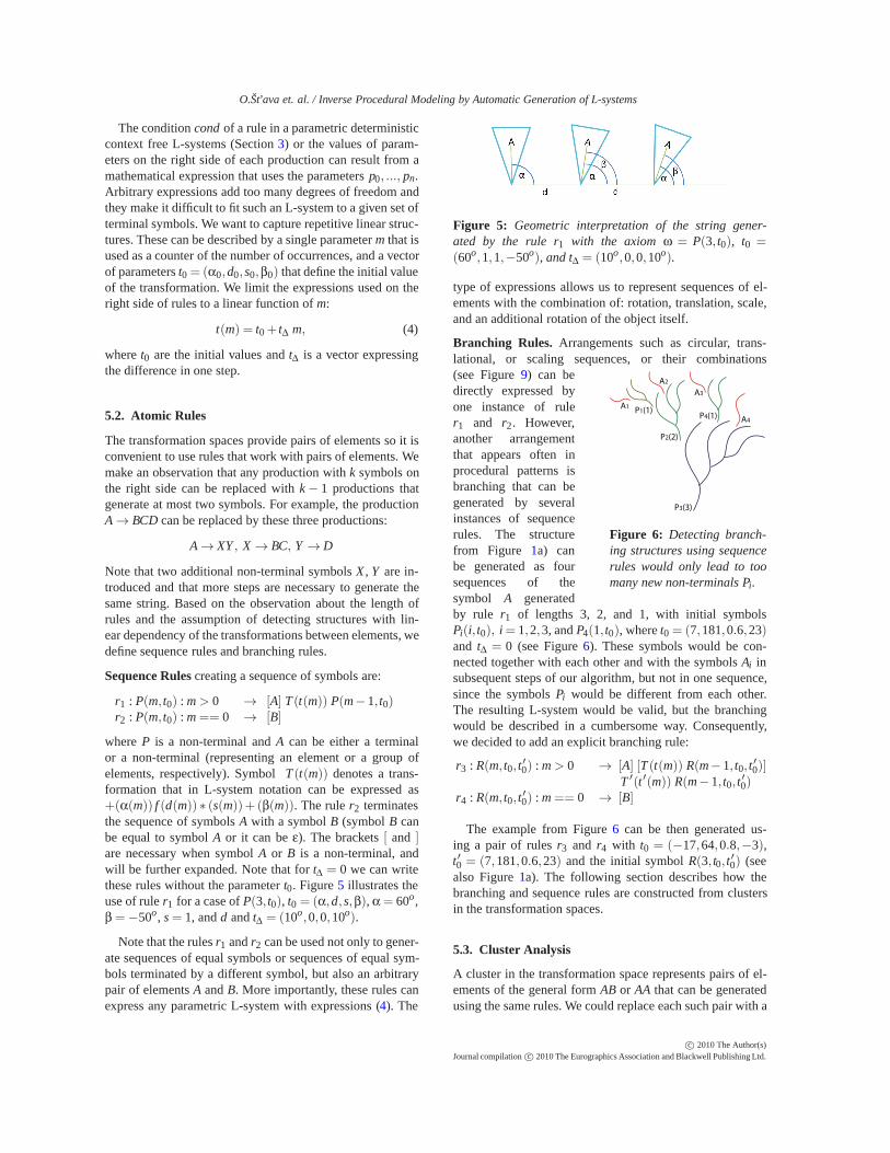
Figure 4: Transformation TA1B1 is a sequence of turtle com-mands +(αA1B1) f (dA1B1)∗ (sA1B1)+ (βA1B1).
If TAi and TBj are transformations from the world coordi-nate system to the element’s coordinate system we expressthe transformation between Ai and Bj (see Figure 4) as
TAiB j = T−1Ai
TBj ,
where T−1Ai
is the inverse transformation to TAi . The trans-formation TAiB j is described by the four values of t0 =(α,d, s,β) that identify a point in a 4D transformation space.We store each point as well as the backward link to the el-ements Ai and Bj. There can be multiple points at the samelocation representing multiple pairs of elements that undergothe same transformation.
L-systems have a great expressive power for structureswith a high level of repetition and that is why we wantto discover relations between groups of similar elements.So instead of using a single transformation space [MGP06,PMW∗08], we use multiple transformation spaces. Specifi-cally, having n terminal symbols we create (n× n) transfor-mation spaces, one for each pair of terminals. In practicalcases such as in Figure 12 we have hundreds of transforma-tion spaces. However, the transformation spaces are usuallynot dense and their analysis is not time consuming.
Let’s recall that multiple points in the dual space corre-spond to similarly distributed elements in the input image.So in the next step, similar to the symmetry recognition ap-proach by [MGP06], we perform mean shift clustering todetermine groups of elements with similar transformations.
5. Procedural Rules Generation
5.1. L-system Parameters
We chose to generate parametric context-free L-systems thatuse only specific parameters and expressions in the rules yetare powerful enough to capture a wide variety of repeatingstructures in distance, angle, and scalings. Ideally, we wouldlike to use a single rule that would be easy to match yet allowfor a wide variety of combinations. We have found matchingthis rule difficult and that is why we generate two kinds ofrules. The first rule provides sequences of symbols and thesecond rule generates branching. It is important to note thatthese two rules are not the direct output of the L-system gen-eration but are the generic rules that are merged into morecomplex rules during the analysis.
c© 2010 The Author(s)Journal compilation c© 2010 The Eurographics Association and Blackwell Publishing Ltd.
O.Št’ava et. al. / Inverse Procedural Modeling by Automatic Generation of L-systems
The condition cond of a rule in a parametric deterministiccontext free L-systems (Section 3) or the values of param-eters on the right side of each production can result from amathematical expression that uses the parameters p0, ..., pn.Arbitrary expressions add too many degrees of freedom andthey make it difficult to fit such an L-system to a given set ofterminal symbols. We want to capture repetitive linear struc-tures. These can be described by a single parameter m that isused as a counter of the number of occurrences, and a vectorof parameters t0 = (α0,d0, s0,β0) that define the initial valueof the transformation. We limit the expressions used on theright side of rules to a linear function of m:
t(m) = t0 + tΔ m, (4)
where t0 are the initial values and tΔ is a vector expressingthe difference in one step.
5.2. Atomic Rules
The transformation spaces provide pairs of elements so it isconvenient to use rules that work with pairs of elements. Wemake an observation that any production with k symbols onthe right side can be replaced with k − 1 productions thatgenerate at most two symbols. For example, the productionA → BCD can be replaced by these three productions:
A → XY , X → BC, Y → D
Note that two additional non-terminal symbols X , Y are in-troduced and that more steps are necessary to generate thesame string. Based on the observation about the length ofrules and the assumption of detecting structures with lin-ear dependency of the transformations between elements, wedefine sequence rules and branching rules.
Sequence Rules creating a sequence of symbols are:
r1 : P(m, t0) : m > 0 → [A] T (t(m)) P(m− 1, t0)r2 : P(m, t0) : m == 0 → [B]
where P is a non-terminal and A can be either a terminalor a non-terminal (representing an element or a group ofelements, respectively). Symbol T (t(m)) denotes a trans-formation that in L-system notation can be expressed as+(α(m)) f (d(m)) ∗ (s(m))+ (β(m)). The rule r2 terminatesthe sequence of symbols A with a symbol B (symbol B canbe equal to symbol A or it can be ε). The brackets [ and ]are necessary when symbol A or B is a non-terminal, andwill be further expanded. Note that for tΔ = 0 we can writethese rules without the parameter t0. Figure 5 illustrates theuse of rule r1 for a case of P(3, t0), t0 = (α,d, s,β), α = 60o,β =−50o, s = 1, and d and tΔ = (10o,0,0,10o).
Note that the rules r1 and r2 can be used not only to gener-ate sequences of equal symbols or sequences of equal sym-bols terminated by a different symbol, but also an arbitrarypair of elements A and B. More importantly, these rules canexpress any parametric L-system with expressions (4). The
Figure 5: Geometric interpretation of the string gener-ated by the rule r1 with the axiom ω = P(3, t0), t0 =(60o,1,1,−50o), and tΔ = (10o,0,0,10o).
type of expressions allows us to represent sequences of el-ements with the combination of: rotation, translation, scale,and an additional rotation of the object itself.
Branching Rules. Arrangements such as circular, trans-lational, or scaling sequences, or their combinations
P3(3)
P2(2)
P1(1)P4(1)
A1
A4
A3
A2
Figure 6: Detecting branch-ing structures using sequencerules would only lead to toomany new non-terminals Pi.
(see Figure 9) can bedirectly expressed byone instance of ruler1 and r2. However,another arrangementthat appears often inprocedural patterns isbranching that can begenerated by severalinstances of sequencerules. The structurefrom Figure 1a) canbe generated as foursequences of thesymbol A generatedby rule r1 of lengths 3, 2, and 1, with initial symbolsPi(i, t0), i = 1,2,3, and P4(1, t0), where t0 = (7,181,0.6,23)and tΔ = 0 (see Figure 6). These symbols would be con-nected together with each other and with the symbols Ai insubsequent steps of our algorithm, but not in one sequence,since the symbols Pi would be different from each other.The resulting L-system would be valid, but the branchingwould be described in a cumbersome way. Consequently,we decided to add an explicit branching rule:
r3 : R(m, t0, t′0) : m > 0 → [A] [T (t(m)) R(m− 1, t0, t
′0)]
T ′(t′(m)) R(m− 1, t0, t′0)
r4 : R(m, t0, t′0) : m == 0 → [B]
The example from Figure 6 can be then generated us-ing a pair of rules r3 and r4 with t0 = (−17,64,0.8,−3),t′0 = (7,181,0.6,23) and the initial symbol R(3, t0, t
′0) (see
also Figure 1a). The following section describes how thebranching and sequence rules are constructed from clustersin the transformation spaces.
5.3. Cluster Analysis
A cluster in the transformation space represents pairs of el-ements of the general form AB or AA that can be generatedusing the same rules. We could replace each such pair with a
c© 2010 The Author(s)Journal compilation c© 2010 The Eurographics Association and Blackwell Publishing Ltd.
O.Št’ava et. al. / Inverse Procedural Modeling by Automatic Generation of L-systems
non-terminal symbol P(1, t0) and the sequence rules r1 andr2. However, the pair can be a part of a larger sequence ofsimilarly oriented elements, so we link the elements in thecluster into a sequence that can be generated by P(m, t0),where m is the number of the elements in the sequence.
We want to detect rules in which the values of α, d, s,and β change linearly with respect to m as expressed by (4).Transformations between elements generated by such a ruleare not represented by a single point in the transformationspace. Instead, they form regular structures. If only one valuechanges with respect to m, say the value of α, there is a se-quence of points in the transformation space with a constantdistance from each other in the α dimension. A similar prob-lem has been addressed by Pauly et al. [PMW∗08] wherethey find a regular grid in a three-dimensional space rep-resenting symmetry transformations in 3D. Because of thechoice of the rules, we need to search for regularly spacedpoints on a line in our transformation spaces only.
However, not all linear sequences of points in the trans-formation space correspond to interesting structures. Struc-tures with linearly changing distance or scale do not appearfrequently in the input scenes and we assume that only theparameters α and β may change. This can be efficiently re-stated as a task of finding clusters in each of the 2D subspaceof the transformation space (d, s) and determining if the val-ues in the remaining two subspaces form regularly spacedpoints and if they belong to one or more sequences of sym-bols that can be generated by the rule r1.
The cluster analysis algorithm attempts to identify se-quential or branching structures:
1. Find clusters Ci in the space (α,d, s,β).2. Find clusters Dj in the two-dimensional subspace (d, s).3. a. Sequential rules: Each point in a cluster represents
a pair of elements. If the second element of a pairis equal to the first element of another pair, we con-nect these two into a sequence. We find the longestsequence in each cluster Ci and Dj.
b. Branching rules: If the second element of a pair is thefirst element of two different pairs (from two differ-ent clusters) it is a branching sequence. We find themost frequently repeated branching sequences in eachcluster Ci and Dj.
5.4. Cluster Selection
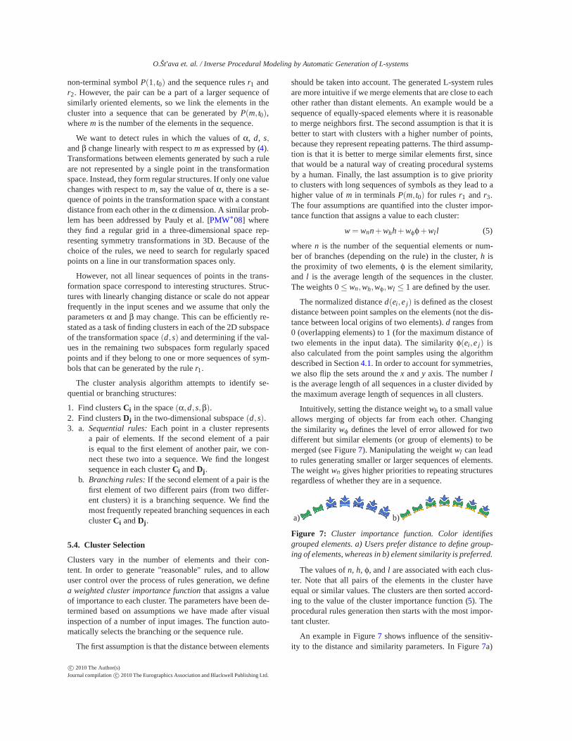
Clusters vary in the number of elements and their con-tent. In order to generate "reasonable" rules, and to allowuser control over the process of rules generation, we definea weighted cluster importance function that assigns a valueof importance to each cluster. The parameters have been de-termined based on assumptions we have made after visualinspection of a number of input images. The function auto-matically selects the branching or the sequence rule.
The first assumption is that the distance between elements
should be taken into account. The generated L-system rulesare more intuitive if we merge elements that are close to eachother rather than distant elements. An example would be asequence of equally-spaced elements where it is reasonableto merge neighbors first. The second assumption is that it isbetter to start with clusters with a higher number of points,because they represent repeating patterns. The third assump-tion is that it is better to merge similar elements first, sincethat would be a natural way of creating procedural systemsby a human. Finally, the last assumption is to give priorityto clusters with long sequences of symbols as they lead to ahigher value of m in terminals P(m, t0) for rules r1 and r3.The four assumptions are quantified into the cluster impor-tance function that assigns a value to each cluster:
w = wnn+whh+wφφ+wll (5)
where n is the number of the sequential elements or num-ber of branches (depending on the rule) in the cluster, h isthe proximity of two elements, φ is the element similarity,and l is the average length of the sequences in the cluster.The weights 0 ≤ wn,wh,wφ,wl ≤ 1 are defined by the user.
The normalized distance d(ei,e j) is defined as the closestdistance between point samples on the elements (not the dis-tance between local origins of two elements). d ranges from0 (overlapping elements) to 1 (for the maximum distance oftwo elements in the input data). The similarity φ(ei,e j) isalso calculated from the point samples using the algorithmdescribed in Section 4.1. In order to account for symmetries,we also flip the sets around the x and y axis. The number lis the average length of all sequences in a cluster divided bythe maximum average length of sequences in all clusters.
Intuitively, setting the distance weight wh to a small valueallows merging of objects far from each other. Changingthe similarity wφ defines the level of error allowed for twodifferent but similar elements (or group of elements) to bemerged (see Figure 7). Manipulating the weight wl can leadto rules generating smaller or larger sequences of elements.The weight wn gives higher priorities to repeating structuresregardless of whether they are in a sequence.
a) b)
Figure 7: Cluster importance function. Color identifiesgrouped elements. a) Users prefer distance to define group-ing of elements, whereas in b) element similarity is preferred.
The values of n, h, φ, and l are associated with each clus-ter. Note that all pairs of the elements in the cluster haveequal or similar values. The clusters are then sorted accord-ing to the value of the cluster importance function (5). Theprocedural rules generation then starts with the most impor-tant cluster.
An example in Figure 7 shows influence of the sensitiv-ity to the distance and similarity parameters. In Figure 7a)
c© 2010 The Author(s)Journal compilation c© 2010 The Eurographics Association and Blackwell Publishing Ltd.
O.Št’ava et. al. / Inverse Procedural Modeling by Automatic Generation of L-systems
the proximity of objects is preferred and the result is twosequences. On the other hand, in Figure 7b) the object sim-ilarity is preferred and the system detects three different se-quences. The weight selection is intuitive but can be prob-lematic for highly noisy input data.
5.5. Rule Generation
In this step we take the cluster with the highest weight andcreate the corresponding sequential or branching rule. Thenew rule is described by a new non-terminal symbol P(m, t0)(or B(m, t0, t
′0) for the branching rule), where m is the recur-
sion depth of the rule and t0 is the non-parametric portion ofthe transformation described by the rule. While t0 (and t′0)are constant for all points in the processed cluster, the valueof m can vary as one cluster can contain multiple sequenceswith different lengths. Because identical rules with differentvalues of m produce different elements, we need to create anew non-terminal symbol for every possible sequence lengthm that is contained in the cluster.
5.6. Higher Level Rules Generation
When the rule is generated we eliminate its elements (orgroup of elements) from the scene and substitute them withthe non-terminal symbol(s). The affected clusters are regen-erated efficiently by keeping mutual links between elementsand the clusters.
Consequently, we replace each occurrence of an elementdescribed by symbol A and transformation TA in any clus-ter by the new non-terminal element P and transformationTP = TA. In this way a group of elements becomes a new ele-ment of the scene. Elements of a sequence or branching otherthan the first one are removed from the associated clusters.This mechanism prevents reclustering. However, the clus-ter importance function must be recalculated for all clusters.We use point sampling to determine distance and similarityof the higher structural elements (groups) in the same wayas for the elements of the input image.
When the clusters are updated with the new element, it canbe merged into higher-level elements in the next iteration. Inthis way we generate complex hierarchies where structureson lower levels are either more abundant or more importantthan the structures on higher levels. The algorithm completeswhen there is a single non-terminal symbol X(m, t0) left.This symbol and its transformation TX form the axiom ofthe L-system ω : TX X(m).
Reinserting the new non-terminal symbols into transfor-mation spaces assures that we find not only the basic com-bination of transformations: rotation, translation, scale, andan additional rotation of the object itself, but also their com-binations. For example, we can find a grid of elements astranslation × translation, but also a grid of elements whereelements at each row are rotated around its origin by an in-creasing angle: translation × translation × rotation, etc.
5.7. Post-processing rules
The generated rules are further processed and simplified.First we clean up the generated rules. For rules that do notuse linear dependency of parameters on m, we skip the pa-rameter t0 and use fixed values in the rule. We eliminatemeaningless transformations such as +(0) and −(0), scal-ing by one, etc. We also combine together rules r1 and r2 forP(1, t0) to a new rule:P → A T B.
Fig ele- rules init. generation totalments [s] of rules [s] time [s]
10 72 4 14 2 1611 1184 182 605 610 121512 500 42 55 154 209
Table 2: Time needed to analyze the figures from this paper.
6. Implementation and Results
We have implemented our system in C++. It uses OpenGLfor visualization of the structures. It reads standard SVG filesand generates corresponding L-systems. Most of the exam-ples in this paper were analyzed within seconds or minutes.The most complicated example (Figure 11) needed twentyminutes (see Table 2).
a) b)
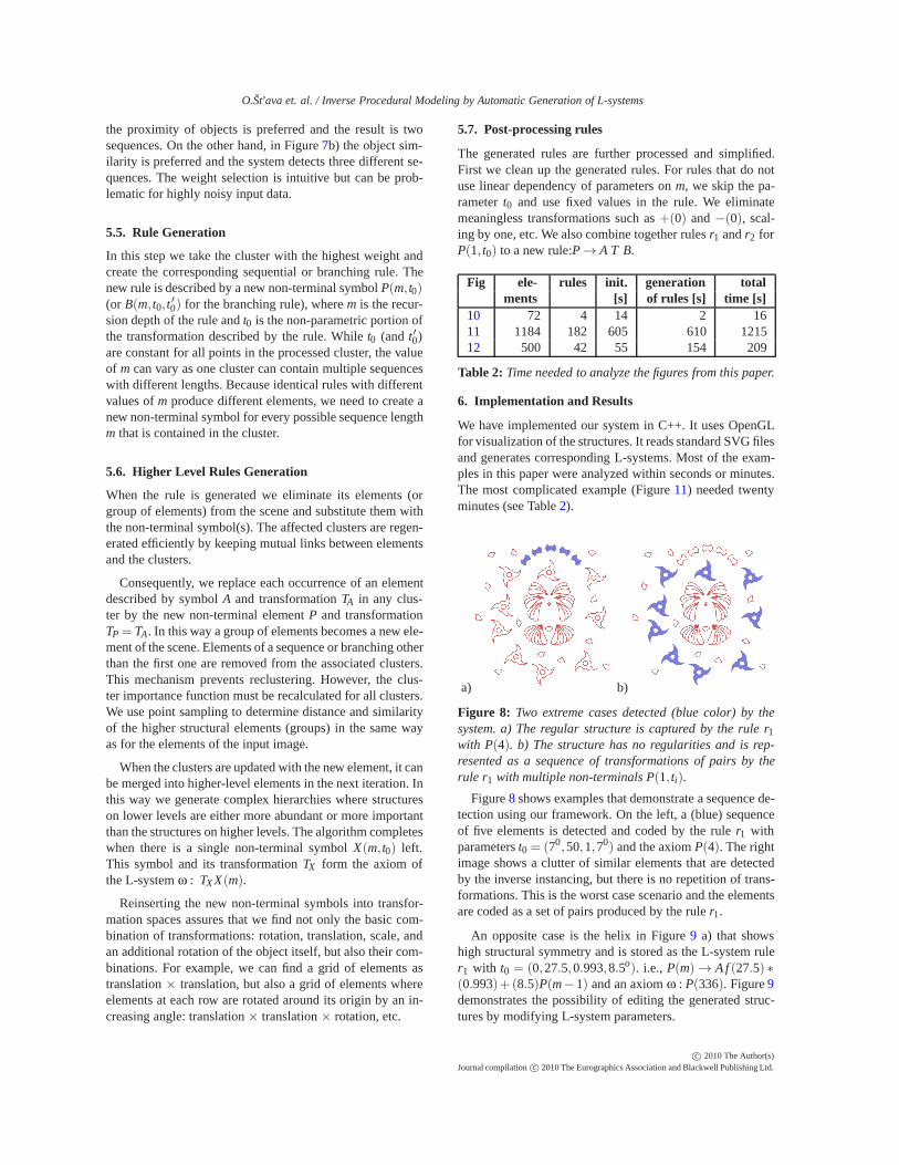
Figure 8: Two extreme cases detected (blue color) by thesystem. a) The regular structure is captured by the rule r1with P(4). b) The structure has no regularities and is rep-resented as a sequence of transformations of pairs by therule r1 with multiple non-terminals P(1, ti).
Figure 8 shows examples that demonstrate a sequence de-tection using our framework. On the left, a (blue) sequenceof five elements is detected and coded by the rule r1 withparameters t0 = (70,50,1,70) and the axiom P(4). The rightimage shows a clutter of similar elements that are detectedby the inverse instancing, but there is no repetition of trans-formations. This is the worst case scenario and the elementsare coded as a set of pairs produced by the rule r1.
An opposite case is the helix in Figure 9 a) that showshigh structural symmetry and is stored as the L-system ruler1 with t0 = (0,27.5,0.993,8.5o). i.e., P(m) → A f (27.5) ∗(0.993)+ (8.5)P(m− 1) and an axiom ω : P(336). Figure 9demonstrates the possibility of editing the generated struc-tures by modifying L-system parameters.
c© 2010 The Author(s)Journal compilation c© 2010 The Eurographics Association and Blackwell Publishing Ltd.
O.Št’ava et. al. / Inverse Procedural Modeling by Automatic Generation of L-systems
a) b) c)
Figure 9: A) Helix detected from an input image is repre-sented by the rule P(m)→ A f (27.5)∗(0.993)+(8.5)P(m−1) and includes m == 336 repetitions. b) Helix generatedfrom the same rule with increased angle between two ele-ments, and c) with increased distance between elements.
A branching structure in Figure 1 a) is recognized andstored as a rule:
R(m) → A[−(17) f (64)− (3)R(m− 1)]
[+(7) f (181)+ (23)R(m− 1)
Figure 1 shows different outputs produced by changing thenumber of recursive calls, internal angles, and scaling. Thisexample shows the expressive power of L-systems.
a) b)
Figure 10: Symmetrization using L-systems. Objects dis-tributed with repetition but large randomness (left) are rec-ognized by setting relaxed sensitivity to angle and distance.The image on the right is generated from the detected rules.
An example of symmetrization on the level of L-systemrules is presented in Figure 10, where hierarchies of similarelements are randomly rotated and translated. The relaxedclustering merges the elements into clusters, the L-systemgenerator produces the axiom P3(2) and rules:
A → Window
P0(m) → A f (13)P0(m− 1)
P1(m) → P0(3)+ (90) f (10)− (90)P1(m− 1)
P2(m) → P1(4)+ (90) f (52)− (90)P2(m− 1)
P3(m) → P2(3) f (51)P3(m− 1)
that lead to the symmetrical composition in Figure 10 b).
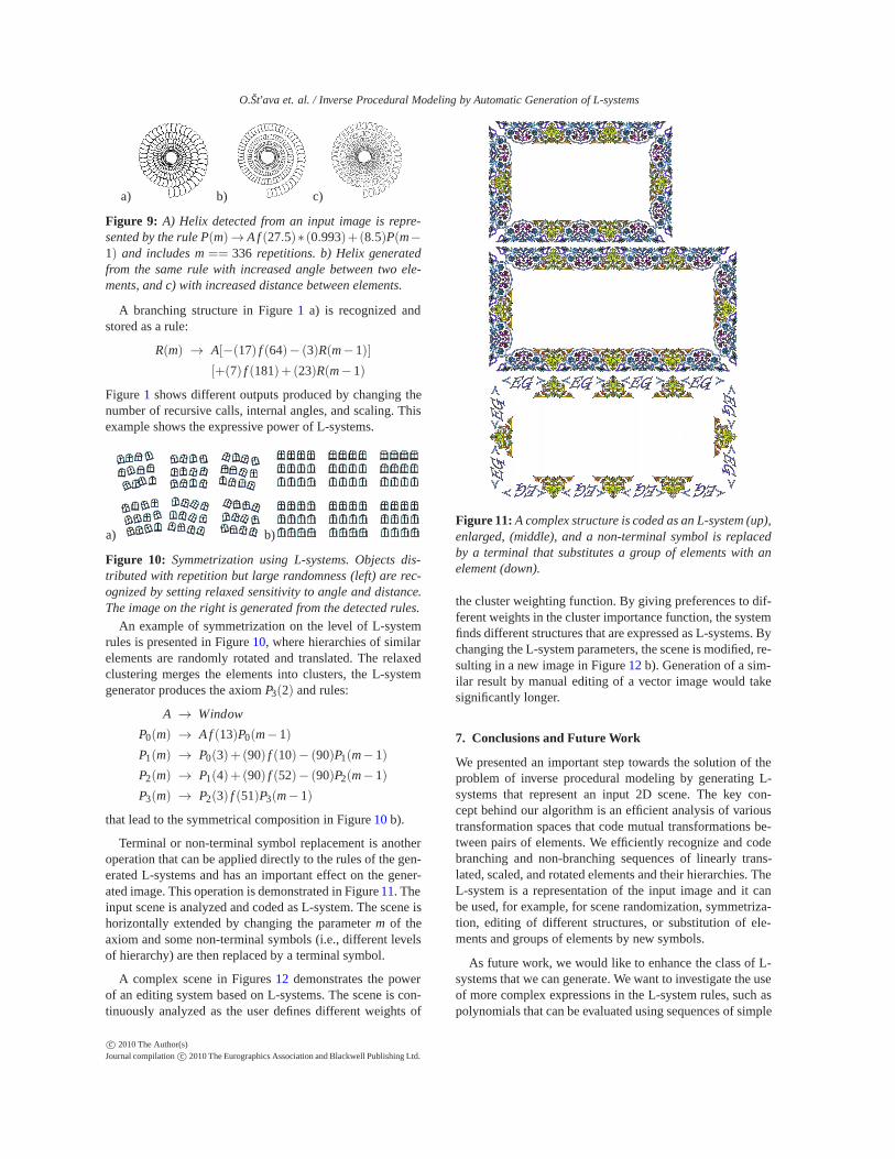
Terminal or non-terminal symbol replacement is anotheroperation that can be applied directly to the rules of the gen-erated L-systems and has an important effect on the gener-ated image. This operation is demonstrated in Figure 11. Theinput scene is analyzed and coded as L-system. The scene ishorizontally extended by changing the parameter m of theaxiom and some non-terminal symbols (i.e., different levelsof hierarchy) are then replaced by a terminal symbol.
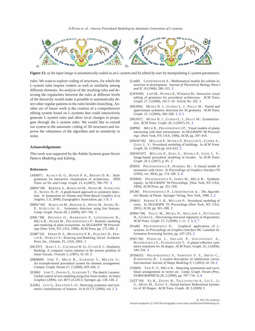
A complex scene in Figures 12 demonstrates the powerof an editing system based on L-systems. The scene is con-tinuously analyzed as the user defines different weights of
Figure 11: A complex structure is coded as an L-system (up),enlarged, (middle), and a non-terminal symbol is replacedby a terminal that substitutes a group of elements with anelement (down).
the cluster weighting function. By giving preferences to dif-ferent weights in the cluster importance function, the systemfinds different structures that are expressed as L-systems. Bychanging the L-system parameters, the scene is modified, re-sulting in a new image in Figure 12 b). Generation of a sim-ilar result by manual editing of a vector image would takesignificantly longer.
7. Conclusions and Future Work
We presented an important step towards the solution of theproblem of inverse procedural modeling by generating L-systems that represent an input 2D scene. The key con-cept behind our algorithm is an efficient analysis of varioustransformation spaces that code mutual transformations be-tween pairs of elements. We efficiently recognize and codebranching and non-branching sequences of linearly trans-lated, scaled, and rotated elements and their hierarchies. TheL-system is a representation of the input image and it canbe used, for example, for scene randomization, symmetriza-tion, editing of different structures, or substitution of ele-ments and groups of elements by new symbols.
As future work, we would like to enhance the class of L-systems that we can generate. We want to investigate the useof more complex expressions in the L-system rules, such aspolynomials that can be evaluated using sequences of simple
c© 2010 The Author(s)Journal compilation c© 2010 The Eurographics Association and Blackwell Publishing Ltd.
O.Št’ava et. al. / Inverse Procedural Modeling by Automatic Generation of L-systems
a) b)
Figure 12: a) An input image is automatically coded as an L-system and b) edited by user by manipulating L-system parameters.
rules. We want to explore coding of structures, for which theL-system rules require context as well as similarity amongdifferent elements. An analysis of the resulting rules and de-tecting the regularities between the rules at different levelsof the hierarchy would make it possible to automatically de-tect other regular patterns in the rules besides branching. An-other are of future work is the creation of a comprehensiveediting system based on L-systems that could interactivelygenerate L-system rules and allow local changes to propa-gate through the L-system rules. We would like to extendour system to the automatic coding of 3D structures and im-prove the robustness of the algorithm and its sensitivity tonoise.
Acknowledgements
This work was supported by the Adobe Systems grant VectorPattern Modeling and Editing.
References
[ARB07] ALIAGA D. G., ROSEN P. A., BEKINS D. R.: Stylegrammars for interactive visualization of architecture. IEEETrans. on Vis. and Comp. Graph. 13, 4 (2007), 786–797. 2
[BBW∗08] BERNER A., BOKELOH M., WAND M., SCHILLING
A., SEIDEL H.-P.: A graph-based approach to symmetry detec-tion. In Symposium on Volume and Point-Based Graphics (LosAngeles, CA, 2008), Eurographics Association, pp. 1–8. 3
[BBW∗09] BOKELOH M., BERNER A., WAND M., SEIDEL H.-P., SCHILLING A.: Symmetry detection using line features.Comp. Graph. Forum 28, 2 (2009), 697–706. 3
[DHL∗98] DEUSSEN O., HANRAHAN P., LINTERMANN B.,MECH R., PHARR M., PRUSINKIEWICZ P.: Realistic modelingand rendering of plant ecosystems. In SIGGRAPH ’98 Proceed-ings (New York, NY, USA, 1998), ACM Press, pp. 275–286. 2
[EMP∗03] EBERT D. S., MUSGRAVE F. K., PEACHEY D., PER-LIN K., WORLEY S.: Texturing and Modeling, 3rd ed. AcademicPress, Inc., Orlando, FL, USA, 2003. 1
[HCF97] HART J. C., COCHRAN W. O., FLYNN P. J.: SimilarityHashing: A computer vision solution to the inverse problem oflinear fractals. Fractals 5, (1997), 35–50. 2
[IMIM08] IJIRI T., MECH R., IGARASHI T., MILLER G.:An example-based procedural system for element arrangement.Comput. Graph. Forum 27, 2 (2008), 429–436. 3
[IOI06] IJIRI T., OWADA S., IGARASHI T.: The sketch l-system:Global control of tree modeling using free-form strokes. In SmartGraphics (2006), vol. 4073 of LNCS, Springer, pp. 138–146. 2
[LE06] LOY G., EKLUNDH J.-O.: Detecting symmetry and sym-metric constellations of features. In In ECCV (2006), vol. 2. 3
[Lin68] LINDENMAYER A.: Mathematical models for cellular in-teraction in development. Journal of Theoretical Biology Parts Iand II, 18 (1968), 280–315. 2
[LWW08] LIPP M., WONKA P., WIMMER M.: Interactive visualediting of grammars for procedural architecture. ACM Trans.Graph. 27, 3 (2008), 102:1–10. Article No. 102. 3
[MGP06] MITRA N. J., GUIBAS L. J., PAULY M.: Partial andapproximate symmetry detection for 3d geometry. ACM Trans.Graph. 25, 3 (2006), 560–568. 1, 3, 5
[MGP07] MITRA N. J., GUIBAS L. J., PAULY M.: Symmetriza-tion. ACM Trans. Graph. 26, 3 (2007), 63. 3
[MP96] MECH R., PRUSINKIEWICZ P.: Visual models of plantsinteracting with their environment. In SIGGRAPH ’96 Proceed-ings (New York, NY, USA, 1996), ACM, pp. 397–410.
[MWH∗06] MÜLLER P., WONKA P., HAEGLER S., ULMER A.,GOOL L. V.: Procedural modeling of buildings. In ACM Trans.Graph. 26, 2 (2006) pp. 614–623. 2
[MZWG07] MÜLLER P., ZENG G., WONKA P., GOOL L. V.:Image-based procedural modeling of facades. In ACM Trans.Graph. 26 3, (2007), p. 85. 2
[PH93] PRUSINKIEWICZ P., HAMMEL M.: A fractal model ofmountains with rivers. In Proceedings of Graphics Interface’93(1993), vol. 30(4), pp. 174–180. 2, 4
[PJM94] PRUSINKIEWICZ P., JAMES M., MECH R.: Synthetictopiary. In SIGGRAPH ’94 Proceedings (New York, NY, USA,1994), ACM Press, pp. 351–358.
[PL90] PRUSINKIEWICZ P., LINDENMAYER A.: The Algorith-mic Beauty of Plants. Springer–Verlag, New York, 1990. 1, 2
[PM01] PARISH Y. I. H., MÜLLER P.: Procedural modeling ofcities. In SIGGRAPH ’01 Proceedings (New York, NY, USA,2001), ACM, pp. 301–308. 2
[PMW∗08] PAULY M., MITRA N., WALLNER J., POTTMANNH., GUIBAS L.: Discovering structural regularity in 3d geometry.ACM Trans. Graph. 27, 3 (2008), 1–11. 1, 3, 5, 7
[Pru86] PRUSINKIEWICZ P.: Graphical applications of L-systems. In Proceedings on Graphics Interface’86, Canadian In-formation Processing Society, pp. 247–253. 2
[PSG∗06] PODOLAK J., SHILANE P., GOLOVINSKIY A.,RUSINKIEWICZ S., FUNKHOUSER T.: A planar-reflective sym-metry transform for 3d shapes. ACM Trans. Graph. 25, 3 (2006),549–559. 3
[PSSK03] PRUSINKIEWICZ P., SAMAVATI F. F., SMITH C.,KARWOWSKI R.: L-system description of subdivision curves.International Journal of Shape Modeling 9, 1 (2003), 41–59. 2
[YM09] YEH Y.-T., MECH R.: Detecting symmetries and curvi-linear arrangements in vector art. Comp. Graph. Forum (Proc.EUROGRAPHICS) 28, 2 (2009), pp. 707–716. 3, 4
[XZT∗09] XU K., ZHANG H., TAGLIASACCHI A., LIU L., LIG., MENG M., XIONG Y.: Partial Intrinsic Reflectional Symme-try of 3D Shapes. ACM Trans. Graph. 28, 5 (2009) 3
c© 2010 The Author(s)Journal compilation c© 2010 The Eurographics Association and Blackwell Publishing Ltd.